1
•
•
•
•
•
•
•
•
•
•
•
•
•
•
•
•
•
•
•
•
•
•
•
•
•
•
•
•
FactoryLink 6.5.0
Reference Guide
FactoryLink 6.5.0 / January / 1998
R
•
•
•
•
©Copyright 1984 - 1998 United States Data Corporation. All rights reserved.
- NOTICE The information contained herein is confidential information of United States Data Corporation, a Delaware corporation,
and is protected by United States copyright and trade secret law and international treaties. This document may refer to
United States Data Corporation as “USDATA.”
Information in this document is subject to change without notice and does not represent a commitment on the part of United
States Data Corporation (“USDATA”). Although the software programs described in this document (the “Software
Programs”) are intended to operate substantially in accordance with the descriptions herein, USDATA does not represent
or warrant that (a) the Software Programs will operate in any way other than in accordance with the most current operating
instructions available from USDATA, (b) the functions performed by the Software Programs will meet the user's
requirements or will operate in the combinations that may be selected for use by the user or any third person, (c) the
operation of the Software Programs will be error free in all circumstances, (d) any defect in a Software Program that is not
material with respect to the functionality thereof as set forth herein will be corrected, (e) the operation of a Software
Program will not be interrupted for short periods of time by reason of a defect therein or by reason of fault on the part of
USDATA, or (f) the Software Programs will achieve the results desired by the user or any third person.
U.S. GOVERNMENT RESTRICTED RIGHTS. The Software is provided with RESTRICTED RIGHTS. Use, duplication, or
disclosure by the government of the United States is subject to restrictions as set forth in subparagraph (c)(1)(ii) of The
Rights in Technical Data and Computer Software clause at DFARS 252.227-7013 or in subparagraphs (c)(1) and (2) of the
Commercial Computer Software—Restricted Rights clause at 48 CFR 52.227-19, as applicable. Contractor/Manufacturer
is United States Data Corporation, 2435 North Central Expressway, Suite 100, Richardson, TX 75080-2759. To the extent
Customer transfers Software to any federal, state or local government agency, Customer shall take all acts necessary to
protect the rights of USDATA in Software, including without limitation all acts described in the regulations referenced
above.
The Software Programs are furnished under a software license or other software agreement and may be used or copied
only in accordance with the terms of the applicable agreement. It is against the law to copy the software on any medium
except as specifically allowed in the applicable agreement. No part of this manual may be reproduced or transmitted in any
form or by any means, electronic or mechanical, including photocopying and recording, for any purpose without the
express written permission of USDATA.
Trademarks. USDATA and FactoryLink are registered trademarks of United States Data Corporation.
Open Software Bus is a registered trademark licensed to United States Data Corporation.
All other brand or product names are trademarks or registered trademarks of their respective holders.
Part title variable applied here in this
book
•
•
•
Table of Contents
•
Reference Guide
Reference Guide
Table of Contents
Preface . . . . . . . . . . . . . . . . . . . . . . . . . . . . . . . . . . . . . . . . . . . . . . . . . . . . . . . 11
Purpose . . . . . . . . . . . . . . . . . . . . . . . . . . . . . . . . . . . . . . . . . . . . . . . . . . . . . . . 11
Audience . . . . . . . . . . . . . . . . . . . . . . . . . . . . . . . . . . . . . . . . . . . . . . . . . . . . . . 11
Structure of the Reference Guide . . . . . . . . . . . . . . . . . . . . . . . . . . . . . . . . . . . 11
How To Use This Manual . . . . . . . . . . . . . . . . . . . . . . . . . . . . . . . . . . . . . . . . 12
Conventions . . . . . . . . . . . . . . . . . . . . . . . . . . . . . . . . . . . . . . . . . . . . . . . . . . 12
Getting Help . . . . . . . . . . . . . . . . . . . . . . . . . . . . . . . . . . . . . . . . . . . . . . . . . . 15
1
Batch Recipe . . . . . . . . . . . . . . . . . . . . . . . . . . . . . . . . . . . . . . . . . . . . . . . 17
Principles of Operation . . . . . . . . . . . . . . . . . . . . . . . . . . . . . . . . . . . . . .
Creating and Animating a Graphics Display . . . . . . . . . . . . . . . . . . . . .
Recipe Control Panel . . . . . . . . . . . . . . . . . . . . . . . . . . . . . . . . . . . . . . . . . . .
Recipe Information Panel . . . . . . . . . . . . . . . . . . . . . . . . . . . . . . . . . . . . . . . .
Batch Recipe Messages . . . . . . . . . . . . . . . . . . . . . . . . . . . . . . . . . . . . . . . . .
2
Database Browser . . . . . . . . . . . . . . . . . . . . . . . . . . . . . . . . . . . . . . . . . . 29
Principles of Operation . . . . . . . . . . . . . . . . . . . . . . . . . . . . . . . . . . . . . . . . . .
Use of Logical Expressions . . . . . . . . . . . . . . . . . . . . . . . . . . . . . . . . . . . . . . .
Configuring Program Arguments . . . . . . . . . . . . . . . . . . . . . . . . . . . . . . . . .
Database Browser Control Panel . . . . . . . . . . . . . . . . . . . . . . . . . . . . . . . . . .
Database Browser Information Panel . . . . . . . . . . . . . . . . . . . . . . . . . . . . . .
Database Browser Status Codes and Status Messages . . . . . . . . . . . . . . . .
3
17
18
19
22
23
29
29
30
32
38
45
Database Logging . . . . . . . . . . . . . . . . . . . . . . . . . . . . . . . . . . . . . . . . . . 57
Database Logging Methodology . . . . . . . . . . . . . . . . . . . . . . . . . . . . . . .
Database Logging Control Panel . . . . . . . . . . . . . . . . . . . . . . . . . . . . . . . . . .
Database Logging Information Panel . . . . . . . . . . . . . . . . . . . . . . . . . . . . . .
Database Logging Messages . . . . . . . . . . . . . . . . . . . . . . . . . . . . . . . . . . . . .
57
59
65
69
FactoryLink ECS / Reference Guide / 3
•
•
Reference Guide
•
•
4
Data-Point Logging . . . . . . . . . . . . . . . . . . . . . . . . . . . . . . . . . . . . . . . . 83
Data-Point Logging Function . . . . . . . . . . . . . . . . . . . . . . . . . . . . . . . . .
Logging Methods . . . . . . . . . . . . . . . . . . . . . . . . . . . . . . . . . . . . . . . . . .
Logging Data . . . . . . . . . . . . . . . . . . . . . . . . . . . . . . . . . . . . . . . . . . . . .
Data-Point Logging Information Panel . . . . . . . . . . . . . . . . . . . . . . . . . . . . . .
Dynamic Logging Control Panel . . . . . . . . . . . . . . . . . . . . . . . . . . . . . . . . . . .
Logging Messages and Codes . . . . . . . . . . . . . . . . . . . . . . . . . . . . . . . . . . . . .
Error Detection . . . . . . . . . . . . . . . . . . . . . . . . . . . . . . . . . . . . . . . . . . . .
Messages . . . . . . . . . . . . . . . . . . . . . . . . . . . . . . . . . . . . . . . . . . . . . . . . .
5
83
84
84
85
87
89
89
90
DDE Client . . . . . . . . . . . . . . . . . . . . . . . . . . . . . . . . . . . . . . . . . . . . . . . . 97
Principles of Operation . . . . . . . . . . . . . . . . . . . . . . . . . . . . . . . . . . . . . . 97
DDE Conversations . . . . . . . . . . . . . . . . . . . . . . . . . . . . . . . . . . . . . . . . 97
Establishing a DDE Link . . . . . . . . . . . . . . . . . . . . . . . . . . . . . . . . . . . . 98
Setting Up DDE Client . . . . . . . . . . . . . . . . . . . . . . . . . . . . . . . . . . . . . . 98
Read/Write Control Panel . . . . . . . . . . . . . . . . . . . . . . . . . . . . . . . . . . . . . . . . 99
Read/Write Information Panel . . . . . . . . . . . . . . . . . . . . . . . . . . . . . . . . . . . 103
DDE Messages . . . . . . . . . . . . . . . . . . . . . . . . . . . . . . . . . . . . . . . . . . . . . . . . 104
Server . . . . . . . . . . . . . . . . . . . . . . . . . . . . . . . . . . . . . . . . . . . . . . . . . . 104
Client . . . . . . . . . . . . . . . . . . . . . . . . . . . . . . . . . . . . . . . . . . . . . . . . . . 105
6
Distributed Alarm Logger . . . . . . . . . . . . . . . . . . . . . . . . . . . . . . . . . 107
Establishing the Alarm Criteria . . . . . . . . . . . . . . . . . . . . . . . . . . . . . .
Alarm Grouping . . . . . . . . . . . . . . . . . . . . . . . . . . . . . . . . . . . . . . . . . .
Parent/Child Relationship . . . . . . . . . . . . . . . . . . . . . . . . . . . . . . . . . .
Alarm Persistence . . . . . . . . . . . . . . . . . . . . . . . . . . . . . . . . . . . . . . . . .
Alarm Distribution . . . . . . . . . . . . . . . . . . . . . . . . . . . . . . . . . . . . . . . .
Alarm Logging . . . . . . . . . . . . . . . . . . . . . . . . . . . . . . . . . . . . . . . . . . .
Distributed Alarm Logger Setup Table . . . . . . . . . . . . . . . . . . . . . . . . . . . . .
General Alarm Setup Control Panel . . . . . . . . . . . . . . . . . . . . . . . . . . . . . . .
Alarm Archive Control Panel . . . . . . . . . . . . . . . . . . . . . . . . . . . . . . . . . . . .
Alarm Local Area Network (LAN) Control Panel . . . . . . . . . . . . . . . . . . . .
Remote Alarm Groups Control Panel . . . . . . . . . . . . . . . . . . . . . . . . . . . . . .
Distributed Alarm Definitions Table . . . . . . . . . . . . . . . . . . . . . . . . . . . . . .
Alarm Group Control Panel . . . . . . . . . . . . . . . . . . . . . . . . . . . . . . . . . . . . . .
Alarm Definition Information Panel . . . . . . . . . . . . . . . . . . . . . . . . . . . . . . .
4 / FactoryLink ECS / Reference Guide
107
107
108
108
108
108
109
110
113
116
118
119
120
126
Reference Guide
Alarm Relations Information Panel . . . . . . . . . . . . . . . . . . . . . . . . . . . . . . .
Distributed Alarm Viewer Setup Table . . . . . . . . . . . . . . . . . . . . . . . . . . . . .
Alarm View Control Panel . . . . . . . . . . . . . . . . . . . . . . . . . . . . . . . . . . . . . . .
Alarm View Output Information Panel . . . . . . . . . . . . . . . . . . . . . . . . . . . . .
Alarm View Logbook Information Panel . . . . . . . . . . . . . . . . . . . . . . . . . . . .
Distributed Alarm Logging Messages . . . . . . . . . . . . . . . . . . . . . . . . . . . . . .
Alarm Logging Messages . . . . . . . . . . . . . . . . . . . . . . . . . . . . . . . . . . .
Alarm Viewer Messages . . . . . . . . . . . . . . . . . . . . . . . . . . . . . . . . . . . .
7
Event and Interval Timer . . . . . . . . . . . . . . . . . . . . . . . . . . . . . . . . . . 155
Principles of Operation . . . . . . . . . . . . . . . . . . . . . . . . . . . . . . . . . . . . .
Changing the Operating System Date and Time . . . . . . . . . . . . . . . . .
Event Timer Information Panel . . . . . . . . . . . . . . . . . . . . . . . . . . . . . . . . . .
Interval Timer Information Panel . . . . . . . . . . . . . . . . . . . . . . . . . . . . . . . . .
Event and Interval Timer Messages . . . . . . . . . . . . . . . . . . . . . . . . . . . . . . .
8
155
156
157
160
162
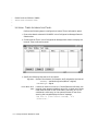
File Manager . . . . . . . . . . . . . . . . . . . . . . . . . . . . . . . . . . . . . . . . . . . . . 167
File Manager Parameters . . . . . . .
File Manager Control Panel . . . . .
File Manager Information Panel . .
File Manager Messages . . . . . . . . .
9
134
136
137
143
145
147
147
152
......
......
......
......
.......
.......
.......
.......
......
......
......
......
.......
.......
.......
.......
......
......
......
......
169
170
176
178
FLLAN . . . . . . . . . . . . . . . . . . . . . . . . . . . . . . . . . . . . . . . . . . . . . . . . . . . 189
Sending and Receiving Data . . . . . . . . . . . . . . . . . . . . . . . . . . . . . . . .
Local and Remote Stations . . . . . . . . . . . . . . . . . . . . . . . . . . . . . . . . . .
Network Groups . . . . . . . . . . . . . . . . . . . . . . . . . . . . . . . . . . . . . . . . . .
Using Multiple Platforms on a Network . . . . . . . . . . . . . . . . . . . . . . . .
Monitoring the Network . . . . . . . . . . . . . . . . . . . . . . . . . . . . . . . . . . . .
Local Station’s Default Values . . . . . . . . . . . . . . . . . . . . . . . . . . . . . . .
Ordering Tag Names . . . . . . . . . . . . . . . . . . . . . . . . . . . . . . . . . . . . . .
Local Area Network Groups Table . . . . . . . . . . . . . . . . . . . . . . . . . . . . . . . .
LAN Local Names Panel . . . . . . . . . . . . . . . . . . . . . . . . . . . . . . . . . . . . . . . .
LAN Remote Names Panel . . . . . . . . . . . . . . . . . . . . . . . . . . . . . . . . . . . . . .
Local Area Network Send Table . . . . . . . . . . . . . . . . . . . . . . . . . . . . . . . . . .
LAN Send Control Panel . . . . . . . . . . . . . . . . . . . . . . . . . . . . . . . . . . . . . . . .
LAN Send Information Panel . . . . . . . . . . . . . . . . . . . . . . . . . . . . . . . . . . . .
189
189
190
190
190
190
190
191
192
193
195
196
200
FactoryLink ECS / Reference Guide / 5
•
•
Reference Guide
•
•
Local Area Network Receive Table . . . . . . . . . . . . . . . . . . . . . . . . . . . . . . . .
LAN Receive Control Panel . . . . . . . . . . . . . . . . . . . . . . . . . . . . . . . . . . . . . .
LAN Receive Information Panel . . . . . . . . . . . . . . . . . . . . . . . . . . . . . . . . . .
Network Monitor Table . . . . . . . . . . . . . . . . . . . . . . . . . . . . . . . . . . . . . . . . .
Network Monitor Information Panel . . . . . . . . . . . . . . . . . . . . . . . . . . . . . .
FLLAN Messages . . . . . . . . . . . . . . . . . . . . . . . . . . . . . . . . . . . . . . . . . . . . . .
10
Historian . . . . . . . . . . . . . . . . . . . . . . . . . . . . . . . . . . . . . . . . . . . . . . . . . 227
Historian Methodology . . . . . . . . . . . . . . . . . . . . . . . . . . . . . . . . . . . . .
Supported Relational Databases . . . . . . . . . . . . . . . . . . . . . . . . . . . . .
dBASE IV Historian . . . . . . . . . . . . . . . . . . . . . . . . . . . . . . . . . . . . . . . . . . . .
dBASE IV Historian Mailbox Information Panel . . . . . . . . . . . . . . . . . . . . .
dBASE IV Historian Information Panel . . . . . . . . . . . . . . . . . . . . . . . . . . . .
Informix Historian . . . . . . . . . . . . . . . . . . . . . . . . . . . . . . . . . . . . . . . . . . . . .
Informix Historian Mailbox Information Panel . . . . . . . . . . . . . . . . . . . . . .
Informix Historian Information Panel . . . . . . . . . . . . . . . . . . . . . . . . . . . . .
ODBC Historian . . . . . . . . . . . . . . . . . . . . . . . . . . . . . . . . . . . . . . . . . . . . . . .
Setting up the ODBC Drivers and Data Sources . . . . . . . . . . . . . . . . .
Data Sources Dialog . . . . . . . . . . . . . . . . . . . . . . . . . . . . . . . . . . . . . . .
Defining Drivers . . . . . . . . . . . . . . . . . . . . . . . . . . . . . . . . . . . . . . . . . .
ODBC Historian Mailbox Information Panel . . . . . . . . . . . . . . . . . . . . . . . .
ODBC Historian Information Panel . . . . . . . . . . . . . . . . . . . . . . . . . . . . . . .
Oracle Historian . . . . . . . . . . . . . . . . . . . . . . . . . . . . . . . . . . . . . . . . . . . . . . .
Oracle Historian Mailbox Information Panel . . . . . . . . . . . . . . . . . . . . . . . .
Oracle7 Historian Information Panel . . . . . . . . . . . . . . . . . . . . . . . . . . . . . .
Sybase Historian . . . . . . . . . . . . . . . . . . . . . . . . . . . . . . . . . . . . . . . . . . . . . .
Sybase Historian Mailbox Information Panel . . . . . . . . . . . . . . . . . . . . . . .
Sybase Historian Information Panel . . . . . . . . . . . . . . . . . . . . . . . . . . . . . . .
Historian Messages . . . . . . . . . . . . . . . . . . . . . . . . . . . . . . . . . . . . . . . . . . . .
Run-time Messages . . . . . . . . . . . . . . . . . . . . . . . . . . . . . . . . . . . . . . . .
Start-up Messages . . . . . . . . . . . . . . . . . . . . . . . . . . . . . . . . . . . . . . . .
Error Messages Recorded in Historian Log Files . . . . . . . . . . . . . . . . .
ODBC Driver and Data Source Messages . . . . . . . . . . . . . . . . . . . . . . .
11
202
203
204
206
207
212
227
228
229
230
231
233
234
235
238
238
239
240
244
245
248
249
250
253
254
255
258
258
264
266
267
Math & Logic . . . . . . . . . . . . . . . . . . . . . . . . . . . . . . . . . . . . . . . . . . . . . 269
Procedures . . . . . . . . . . . . . . . . . . . . . . . . . . . . . . . . . . . . . . . . . . . . . . 269
6 / FactoryLink ECS / Reference Guide
Reference Guide
Creating Programs . . . . . . . . . . . . . . . . . . . . . . . . . . . . . . . . . . . . . . . .
Modes . . . . . . . . . . . . . . . . . . . . . . . . . . . . . . . . . . . . . . . . . . . . . . . . . .
Triggering/Calling . . . . . . . . . . . . . . . . . . . . . . . . . . . . . . . . . . . . . . . .
Error Messages . . . . . . . . . . . . . . . . . . . . . . . . . . . . . . . . . . . . . . . . . . . . . . . .
12
Persistence . . . . . . . . . . . . . . . . . . . . . . . . . . . . . . . . . . . . . . . . . . . . . . . . 295
Persistence Overview . . . . . . . . . . . . . . . . . . . . . . . . . . . . . . . . . . . . . . . . . . .
Principles of Operation . . . . . . . . . . . . . . . . . . . . . . . . . . . . . . . . . . . . .
Resolving Configuration Changes . . . . . . . . . . . . . . . . . . . . . . . . . . . .
Persistence Save Information Panel . . . . . . . . . . . . . . . . . . . . . . . . . . . . . . .
Persistence Messages . . . . . . . . . . . . . . . . . . . . . . . . . . . . . . . . . . . . . . . . . . .
13
295
295
296
297
299
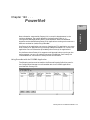
PowerNet . . . . . . . . . . . . . . . . . . . . . . . . . . . . . . . . . . . . . . . . . . . . . . . . . 303
Using PowerNet with the FLDEMO Application . . . . . . . . . . . . . . . . .
Method of Data Transfer . . . . . . . . . . . . . . . . . . . . . . . . . . . . . . . . . . . .
Client-to-Server Data Transfer . . . . . . . . . . . . . . . . . . . . . . . . . . . . . . .
Tag Naming Conventions . . . . . . . . . . . . . . . . . . . . . . . . . . . . . . . . . . .
Tag Type Conversion . . . . . . . . . . . . . . . . . . . . . . . . . . . . . . . . . . . . . . .
External Domain Definition Panel . . . . . . . . . . . . . . . . . . . . . . . . . . . . . . . .
System Configuration Information Panel . . . . . . . . . . . . . . . . . . . . . . . . . . .
PowerNet Messages . . . . . . . . . . . . . . . . . . . . . . . . . . . . . . . . . . . . . . . . . . . .
14
269
269
270
271
303
304
304
304
305
305
309
311
Power SPC . . . . . . . . . . . . . . . . . . . . . . . . . . . . . . . . . . . . . . . . . . . . . . . 315
Sample Plans Table . . . . . . . . . . . . . . . . . . . . . . . . . . . . . . . . . . . . . . . . . . . .
Sample Plan Definition Panel . . . . . . . . . . . . . . . . . . . . . . . . . . . . . . . . . . . .
Collection Control Panel . . . . . . . . . . . . . . . . . . . . . . . . . . . . . . . . . . . . . . . .
Sample Plan Calculation Control Panel . . . . . . . . . . . . . . . . . . . . . . . . . . . .
Monitor Control Panel . . . . . . . . . . . . . . . . . . . . . . . . . . . . . . . . . . . . . . . . . .
Power SPC Processes Table . . . . . . . . . . . . . . . . . . . . . . . . . . . . . . . . . . . . . .
Process Definition Panel . . . . . . . . . . . . . . . . . . . . . . . . . . . . . . . . . . . . . . . .
Data Collection Control Panel . . . . . . . . . . . . . . . . . . . . . . . . . . . . . . . . . . . .
Auxiliary Collection Panel . . . . . . . . . . . . . . . . . . . . . . . . . . . . . . . . . . . . . . .
Acceptance Sampling Panel . . . . . . . . . . . . . . . . . . . . . . . . . . . . . . . . . . . . . .
Calculation Control Panel . . . . . . . . . . . . . . . . . . . . . . . . . . . . . . . . . . . . . . .
Process Monitor Control Panel . . . . . . . . . . . . . . . . . . . . . . . . . . . . . . . . . . .
SPC Charts Table . . . . . . . . . . . . . . . . . . . . . . . . . . . . . . . . . . . . . . . . . . . . . .
317
318
321
324
329
331
332
339
343
345
348
359
364
FactoryLink ECS / Reference Guide / 7
•
•
Reference Guide
•
•
Chart Definition Panel . . . . . . . . . . . . . . . . . . . . . . . . . . . . . . . . . . . . . . . . . .
Calculation Display Panel . . . . . . . . . . . . . . . . . . . . . . . . . . . . . . . . . . . . . . .
Raw Data Display Panel . . . . . . . . . . . . . . . . . . . . . . . . . . . . . . . . . . . . . . . .
Auxiliary Data Display Panel . . . . . . . . . . . . . . . . . . . . . . . . . . . . . . . . . . . .
Control Chart Panel . . . . . . . . . . . . . . . . . . . . . . . . . . . . . . . . . . . . . . . . . . . .
Bar Chart Display Panel . . . . . . . . . . . . . . . . . . . . . . . . . . . . . . . . . . . . . . . .
Chart Information Panel . . . . . . . . . . . . . . . . . . . . . . . . . . . . . . . . . . . . . . . .
Ad Hoc Chart Calculation Panel . . . . . . . . . . . . . . . . . . . . . . . . . . . . . . . . . .
Chart Style Panel . . . . . . . . . . . . . . . . . . . . . . . . . . . . . . . . . . . . . . . . . . . . . .
User-Defined Cause Code Table . . . . . . . . . . . . . . . . . . . . . . . . . . . . . . . . . .
Cause Code Definition Panel . . . . . . . . . . . . . . . . . . . . . . . . . . . . . . . . . . . . .
Run Rule Definition Panel . . . . . . . . . . . . . . . . . . . . . . . . . . . . . . . . . . . . . . .
Auxiliary Schema Definition Panel . . . . . . . . . . . . . . . . . . . . . . . . . . . . . . . .
Auxiliary Schema Control Panel . . . . . . . . . . . . . . . . . . . . . . . . . . . . . . . . . .
Power SPC Messages . . . . . . . . . . . . . . . . . . . . . . . . . . . . . . . . . . . . . . . . . . .
15
365
372
376
379
381
384
389
391
396
398
399
401
406
408
410
Print Spooler . . . . . . . . . . . . . . . . . . . . . . . . . . . . . . . . . . . . . . . . . . . . . 449
Print Spooler Information Panel . . . . . . . . . . . . . . . . . . . . . . . . . . . . . . . . . . 450
Print Spooler Messages . . . . . . . . . . . . . . . . . . . . . . . . . . . . . . . . . . . . . . . . . 455
16
Programmable Counters . . . . . . . . . . . . . . . . . . . . . . . . . . . . . . . . . . . 459
Principles of Operation . . . . . . . . . . . . . . . . . . . . . . . . . . . . . . . . . . . . . 459
Programmable Counters Information Panel . . . . . . . . . . . . . . . . . . . . . . . . 461
Programmable Counters Messages . . . . . . . . . . . . . . . . . . . . . . . . . . . . . . . . 465
17
Report Generator . . . . . . . . . . . . . . . . . . . . . . . . . . . . . . . . . . . . . . . . . . 467
Components of a Format File . . . . . . . . . . . . . . . . . . . . . . . . . . . . . . . .
Keywords . . . . . . . . . . . . . . . . . . . . . . . . . . . . . . . . . . . . . . . . . . . . . . .
Placement of Reported Data . . . . . . . . . . . . . . . . . . . . . . . . . . . . . . . . .
Trigger Actions . . . . . . . . . . . . . . . . . . . . . . . . . . . . . . . . . . . . . . . . . . .
Report Format Variations . . . . . . . . . . . . . . . . . . . . . . . . . . . . . . . . . . .
Complete Triggers . . . . . . . . . . . . . . . . . . . . . . . . . . . . . . . . . . . . . . . . .
Escape Sequences . . . . . . . . . . . . . . . . . . . . . . . . . . . . . . . . . . . . . . . . .
Report Generator Format Panel . . . . . . . . . . . . . . . . . . . . . . . . . . . . . . . . . .
Report Generator Control Panel . . . . . . . . . . . . . . . . . . . . . . . . . . . . . . . . . .
Report Generator Information Panel . . . . . . . . . . . . . . . . . . . . . . . . . . . . . .
8 / FactoryLink ECS / Reference Guide
467
467
468
468
468
468
468
469
471
476
Reference Guide
Report Generator Messages . . . . . . . . . . . . . . . . . . . . . . . . . . . . . . . . . . . . . . 478
18
Scaling and Deadbanding . . . . . . . . . . . . . . . . . . . . . . . . . . . . . . . . . 483
Principles of Operation . . . . . . . . . . . . . . . . . . . . . . . . . . . . . . . . . . . . . 483
Scaling and Deadbanding Information Panel . . . . . . . . . . . . . . . . . . . . . . . . 485
Scaling and Deadbanding Error Messages . . . . . . . . . . . . . . . . . . . . . . . . . . 487
19
Schemas . . . . . . . . . . . . . . . . . . . . . . . . . . . . . . . . . . . . . . . . . . . . . . . . . . 493
Database vs. Data-Point Logging . . . . . . . . . . . . . . . . . . . . . . . . . .
Trending . . . . . . . . . . . . . . . . . . . . . . . . . . . . . . . . . . . . . . . . . . . . . . . .
Database Logging Schemas . . . . . . . . . . . . . . . . . . . . . . . . . . . . . . . . .
Database Schema Creation Table . . . . . . . . . . . . . . . . . . . . . . . . . . . . . . . . .
Schema Control Panel . . . . . . . . . . . . . . . . . . . . . . . . . . . . . . . . . . . . . . . . . .
Schema Information Panel . . . . . . . . . . . . . . . . . . . . . . . . . . . . . . . . . . . . . .
Index Information Panel . . . . . . . . . . . . . . . . . . . . . . . . . . . . . . . . . . . . . . . .
Security Event Logging Schema Panel . . . . . . . . . . . . . . . . . . . . . . . . . . . . .
Data-Point Logging . . . . . . . . . . . . . . . . . . . . . . . . . . . . . . . . . . . . . . . . . . . .
Data-Point Schema Control Panel . . . . . . . . . . . . . . . . . . . . . . . . . . . . . . . .
Data-Point Logging Control Panel . . . . . . . . . . . . . . . . . . . . . . . . . . . . . . . .
20
Trending . . . . . . . . . . . . . . . . . . . . . . . . . . . . . . . . . . . . . . . . . . . . . . . . . 511
Trending Methodology . . . . . . . . . . . . . . . . . . . . . . . . . . . . . . . . . . . . .
Real-time Only Trending . . . . . . . . . . . . . . . . . . . . . . . . . . . . . . . . . . .
Chart Types . . . . . . . . . . . . . . . . . . . . . . . . . . . . . . . . . . . . . . . . . . . . . .
Switching Between Real-time and Historical Mode . . . . . . . . . . . . . . .
Zooming and Panning . . . . . . . . . . . . . . . . . . . . . . . . . . . . . . . . . . . . .
Pen Types . . . . . . . . . . . . . . . . . . . . . . . . . . . . . . . . . . . . . . . . . . . . . . .
Value Cursor . . . . . . . . . . . . . . . . . . . . . . . . . . . . . . . . . . . . . . . . . . . . .
Configuring Program Arguments . . . . . . . . . . . . . . . . . . . . . . . . . . . . .
Trend Database Tables Panel . . . . . . . . . . . . . . . . . . . . . . . . . . . . . . . . . . . .
Trending Messages . . . . . . . . . . . . . . . . . . . . . . . . . . . . . . . . . . . . . . . . . . . . .
21
493
494
494
495
496
498
502
504
506
507
509
511
511
511
512
512
512
512
512
513
515
Window Management . . . . . . . . . . . . . . . . . . . . . . . . . . . . . . . . . . . . . 523
System Configuration Information Panel . . . . . . . . . . . . . . . . . . . . . . . . . . . 524
Window Management Control Panel . . . . . . . . . . . . . . . . . . . . . . . . . . . . . . 531
FactoryLink ECS / Reference Guide / 9
•
•
Reference Guide
•
•
Index . . . . . . . . . . . . . . . . . . . . . . . . . . . . . . . . . . . . . . . . . . . . . . . . . . . . . 533
10 / FactoryLink ECS / Reference Guide
•
•
•
•
•
•
•
•
•
•
•
•
•
•
•
•
•
•
•
•
•
•
•
•
•
•
•
•
•
•
Preface
P URPOSE
The FactoryLink ECS Reference Guide is a collection of field-by-field descriptions
of the configuration panels used to configure the network operations.
This guide is prepared to present the details of configuring the panels for the
twenty-one FactoryLink tasks that programmers use in completing applications.
The following guidelines help focus our purpose and goals to meet customer
requirements:
• Accuracy is paramount—This FactoryLink documentation must provide
accurate and reliable information and procedures.
• Time is valuable—This FactoryLink documentation must guide the
programmer through what he needs to know quickly and efficiently.
A UDIENCE
The major audience of this manual is programmers who design and construct
FactoryLink applications .
• develop communications interfaces to computers or devices for which standard
interface tasks are not already developed.
In addition, FactoryLink Customer Support Services personnel use the procedures
and examples included here to help you develop and troubleshoot your
applications.
S TRUCTURE
OF THE
R EFERENCE G UIDE
The Reference Guide is part of the Core set of manuals in the overall FactoryLink
Documentation Set. Refer to the Preface in Fundamentals for the structure of the
entire Documentation Set.
This manual is divided into twenty-one chapters:
• Batch Recipe
• Database Browser
• Database Logging
• Data-Point Logging
• DDE Client
• Distributed Alarm Logger
FactoryLink ECS / Reference Guide / 11
•
•
How To Use This Manual
•
•
• Event and Interval Timer
• File Manager
• FLLAN
• Historian
• Math & Logic
• Persistence
• PowerNet
• Power SPC
• Print Spooler
• Programmable Counters
• Report Generator
• Scaling & Deadbanding
• Schemas
• Trending
• Window Management
Each chapter begins with a brief introduction followed by the configuration
information for the panels used in that task and ends with the messages
associated with that task. The exception to this structure is Math & Logic, which
presents only the messages for that task.
H OW TO U SE T HIS M ANUAL
The material in this manual is presented alphabetically by task. It is intended to
be utilized on a task-by-task as needed basis.
C ONVENTIONS
The material in the Documentation Set adheres to the guidelines published in The
Digital Technical Documentation Handbook by Schultz, Darrow, Kavanagh, and
Morse; Developing International User Information by Jones, Kennelly, Mueller,
Sweezy, Thomas, and Velez; and corporate style guidelines.
12 / FactoryLink ECS / Reference Guide
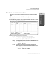
Conventions
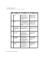
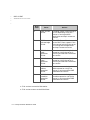
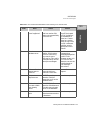
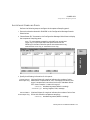
This manual uses the following conventions.
Convention
Description
italic type
Italic type is used to denote user-supplied variables in
command examples.
Italic type also sets off references to specific
documents.
monospace type
Monospace type is used to denote command names
and code examples or example output.
bold monospace type
Bold monospace type is used in command examples to
indicate words that must be typed literally.
sans serif type
Sans Serif type is used to set off field names, button
names, and keys on the keyboard.
blue type
Blue type is used for headings and to call attention to
information within the text.
press nnnnn
Press is used to denote a key on the keyboard. The
key name will appear in a sans serif type.
click on nnnnn
Click on is used to denote a button on the screen. The
button name displays in a sans serif type.
Shift+F1
The + indicates the keys must be pressed
simultaneously.
Shift+F1 indicates you hold down the Shift key while
you press another key or mouse button (indicated
here by F1).
Other key combinations are presented in the same
manner.
F1 F2 F3
The space between the key callouts indicates press
and release.
The key sequence F1 F2 F3 indicates you press and
release F1, then F2, and then F3.
Other key combinations are presented in the same
manner.
FactoryLink ECS / Reference Guide / 13
•
•
Conventions
•
•
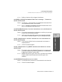
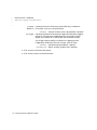
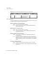
Convention
Description
File>Open
The > indicates a progression through a menu
sequence.
File>Open indicates you choose Open from the File
menu to perform the required action.
Other menu sequences are presented in the same
manner.
FLAPP\user\drw\mydrw.g
The \ indicates the directory structure for the listed
file.
FLAPP\user\drw\mydrw.g indicates the drawing file
mydrw.g is located in the drw sub-directory of the user
sub-directory to the FLAPP directory.
Other directory structures are presented in the same
manner.
[]
Brackets indicate an optional argument. You can
choose none, one, or all of the options.
{ } and |
Braces indicate a choice. You must choose one of the
elements. The vertical bar separates choices within
braces.
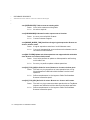
Example Syntax
Example syntax using these conventions is provided below:
command input_file [input_file…] {a|b} output_file
where
command
input_file
[input_file…]
{a|b}
output_file
is typed as it is displayed in the syntax.
indicates a variable the user supplies.
indicates the user can optionally supply multiple input file
names, each name separated by a space.
indicates either the a or b must be specified as an argument.
indicates the user must specify an output file.
14 / FactoryLink ECS / Reference Guide
Getting Help
G ETTING H ELP
Contact your Sales or Customer Support Representative for help troubleshooting
problems.
Also, help files are included for each configuration panel. These are accessed by
clicking on Help on the panel menu bar.
FactoryLink ECS / Reference Guide / 15
•
•
Getting Help
•
•
16 / FactoryLink ECS / Reference Guide
•
•
•
•
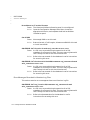
Chapter 111
Batch Recipe
111
Principles of Operation
A batch recipe is a collection of elements in the real-time database grouped
together for some purpose. These elements can contain internally-generated or
operator-entered values.
You can perform the following functions with Batch Recipe:
• Define up to 8,000 different recipe templates, each associated with a virtually
unlimited number of files.
• Store batch recipes in disk files so the total number of different recipes stored
on a system is limited only by available disk space.
• Store each batch recipe file under a standard file name.
• Specify up to 8,000 elements for one batch recipe template.
• Use with any of the five FactoryLink data types: digital, analog, long analog,
floating-point, and message.
You can configure Batch Recipe for use in many diverse applications. For example,
a program can use a graphic display for the entry of application values and write
these values to an external device using the FactoryLink EDI task. Batch Recipe
can save these element values in a recipe so the program can then read the values
from the batch recipe file.
Sample applications that use a single batch recipe template include:
• Producing a particular line of paint. You can use multiple files using the same
recipe template to set various hues or colors of the paint being produced.
• Setting up various external devices with different files for days of the week, end
of the month, and other schedules.
• Setting up an environment for a testing procedure with various files to
establish different sets of testing parameters.
FactoryLink 6.5.0 / Reference Guide / 17
Batch Recipe
The FactoryLink Batch Recipe task transfers sets of predefined values, sometimes
called recipes, between binary disk files and selected elements and between the
real-time database and an external device.
•
BATCH RECIPE
•
•
•
You can use batch recipes in conjunction any FactoryLink task because each
FactoryLink task communicates with other tasks through the real-time database.
Batch Recipe executes as a background task. The task does not require operator
intervention at run time unless you design the application to require it.
You can configure Batch Recipe to be triggered by events, timers, or operator
commands, such as:
• An external device read operation
• A Math & Logic calculation, either Interpreted or Compiled
• An activity from another station on a network
• Input from the operator using a keyboard or pointing device
Monitor the Run-Time Manager screen to determine the status of Batch Recipe at
run time.
When performing a platform-dependent FLSAVE, FactoryLink saves recipe files;
however, when performing a platform-independent or multiplatform FLSAVE,
FactoryLink does not save recipe files.
Creating and Animating a Graphics Display
You can create and animate a graphic display using the Application Editor for an
operator to use when selecting a recipe name and to set or modify values in a
recipe.
18 / FactoryLink 6.5.0 / Reference Guide
BATCH RECIPE
Recipe Control Panel
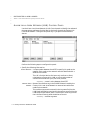
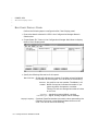
R ECIPE C ONTROL P ANEL
111
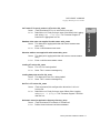
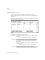
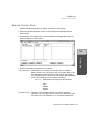
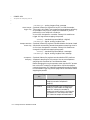
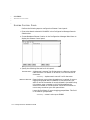
Perform the following steps to configure the Recipe Control panel:
1 Ensure the domain selected is SHARED in the Configuration Manager Domain
2 Choose Recipe in the Configuration Manager Main Menu to display the Recipe
Control panel.
3 Specify the following information for this panel:
Recipe Name
Alphanumeric string of 1 to 16 characters that specifies the
unique name of the recipe template to be defined or modified. Use
View>Search to display a recipe template that already exists.
Valid Entry: alphanumeric string of 1 to 16 characters
Read Trigger
Name of an element that initiates a read operation. When Recipe
detects this element has been forced to 1 (ON), the task reads the
binary values from the disk file specified in the File Spec. and File
Spec. Variable fields and transfers them to the elements specified
in the Recipe Information panel.
Valid Entry: standard tag name
FactoryLink 6.5.0 / Reference Guide / 19
Batch Recipe
Selection box.
•
BATCH RECIPE
•
Recipe Control Panel
•
•
Save Trigger
Name of a digital element that initiates a write operation. When
the value of this element changes to 1 (ON), Recipe collects the
current values of the elements specified in the Recipe Information
panel and writes them to the binary disk file specified in the File
Spec. and File Spec.Variable fields.
Valid Entry: standard tag name
Valid Data Type: digital
File Spec.
Variable specifier that uses the value of the File Spec. Variable
element as the variable.
Sample Path—if you specify the Path File Name
DISK:/RECIPE/PAINT%03d.RCP, and define the File Spec.
Variable element as an analog data type, value 23, the system
generates the following file name:
DISK:/recipe/paint023.rcp
Because the default path is
/FLAPP/FLNAME/FLDOMAIN/FLUSER/RCP, the File Spec. of
PAINT/%s.RCP and the File Spec. Variable containing a message
data type value of red generate the following file name:
/FLAPP/FLNAME/FLDOMAIN/FLUSER/rcp/paint/red.rcp
If the File Spec. Variable is absent, the file name is generated from
the File Spec. and/or the default path name
(/FLAPP/FLNAME/FLDOMAIN/FLUSER/RCP). If the File Spec. is
absent, it defaults to %s,%d,%1d, or %-8.3f as appropriate for the
File Spec. Variable data type.
File Spec. Variable
Name of an element whose value is used with the entry in the File
Spec. field to form the file/path name for a binary disk file that
contains a specific recipe.
Valid Entry: standard tag name
Max. Msg. Length
Number between 1 and 255 that specifies the maximum number
of characters in a message.
Valid Entry: numeric value between 1 and 255
20 / FactoryLink 6.5.0 / Reference Guide
BATCH RECIPE
Recipe Control Panel
Forced Write
YES Sets change-status flags for all elements in a
read operation.
NO Causes change-status flags to be set only for
elements whose values have changed since the
last read operation. This is the default.
Completion Trigger
Name of an element whose value is forced to 1 (ON) by the Recipe
task when a read or write operation is completed. The value of
the Completion Trigger element is 0 (OFF) when the program
begins loading a new batch recipe file from the specified drive to
the real-time database and is 1 (ON) (becomes a 1 and has its
change-status flag set to 1) when the file finishes loading.
Completion Triggers are used in multiple operations. For
example, the Completion Trigger can initiate a write of a recipe to
an external device or it can initiate a message to the operator on a
graphics screen stating an operation has been performed. The
Math & Logic task can check the trigger to determine successful
reading or writing of the recipe.
Valid Entry: standard tag name
Completion Status
Name of an element set to 0 (OFF) when the last recipe read or
write is completed without an error or set to 1 (ON) when the last
recipe read or write is completed with an error.
Valid Entry: standard tag name
4 Click on Enter to save the information.
5 Click on Exit to return to the Main Menu.
FactoryLink 6.5.0 / Reference Guide / 21
111
Batch Recipe
Indicates whether all change-status flags are to be set to 1 (ON)
when a read operation occurs. Because of this option, in a read
operation, Batch Recipe can set change-status flags for all
elements specified in a recipe rather than only for those elements
whose values have changed since the last read operation. Refer to
FactoryLink Fundamentals for information about change-status
flags. This can be one of the following:
•
BATCH RECIPE
•
Recipe Information Panel
•
•
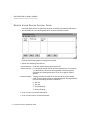
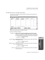
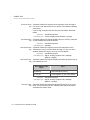
R ECIPE I NFORMATION P ANEL
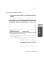
Perform the following steps to configure the Recipe Information panel:
1 Ensure the domain selected is SHARED in the Configuration Manager Domain
Selection box.
2 Choose Recipe in the Configuration Manager Main Menu to display the Recipe
Information panel.
3 Specify the following information for this panel:
Tag Name
Name of each element to be read or written.
Valid Entry: standard tag name
Tag Type
Data type of the element specified in the Tag Name field above.
The data type is displayed automatically after you select a data
type from the Tag Definition dialog and click on Enter.
Valid Entry: data type
Tag Description
Description of the element specified in the Tag Name field. The
description is displayed automatically if you enter a description
in the Tag Definition dialog and click on Enter.
Valid Entry: element description
4 Click on Enter to save the information.
5 Click on Exit to return to the Main Menu.
22 / FactoryLink 6.5.0 / Reference Guide
BATCH RECIPE
Batch Recipe Messages
B ATCH R ECIPE M ESSAGES
111
The following status and error messages can occur during Batch Recipe run time.
Causes and corrective actions are listed for each error message.
Cause:
The file name or pathname may be invalid or the disk may be
full.
Action:
Specify the Path File Name correctly. If the Path File Name is
correct, ensure the directory exists. Run CHKDSK, fsck, ANALYZE,
or any disk diagnostic program to determine whether the disk is
full. Delete unnecessary files if the disk is full or nearly full.
Can’t find recipe recipe filename
Cause:
The task cannot locate the specified recipe file.
Action:
Either the recipe file does not exist or the name of the file was
entered incorrectly.
Error reading CT header
Cause:
Either the file /CT/RECIPE.CT is corrupt or the .CT script file
(/FLINK/CTG/RECIPE.CTG) and the FactoryLink Run-Time
version are not the same version.
Action:
Delete the file /FLAPP/CT/RECIPE.CT. Restart the application to
rebuild the file, or execute CTGEN RECIPE.CT -V3.
In Windows NT and Windows 95, choose Start>Run and type
CTGEN -ac:\FLAPP RECIPE.CT -V3 at the command line. This
sets the FLAPP and executes CTGEN.
In OS/2 and UNIX, set FLAPP before running CTGEN.
Error reading CT index
Cause:
The file /CT/RECIPE.CT has been damaged.
Action:
Delete the file /FLAPP/CT/RECIPE.CT. Restart the application to
rebuild the file, or execute CTGEN RECIPE.CT -V3.
In Windows NT and Windows 95, choose Start>Run and type
FactoryLink 6.5.0 / Reference Guide / 23
Batch Recipe
Can’t create recipe file recipe filename
•
BATCH RECIPE
•
Batch Recipe Messages
•
•
CTGEN -ac:\FLAPP RECIPE.CT -V3 at the command line. This
sets the FLAPP and executes CTGEN.
In OS/2 and UNIX, set FLAPP before running CTGEN.
Error reading CT record
Cause:
Either the file /CT/RECIPE.CT is corrupt, or the .CT script file
(/FLINK/CTG/RECIPE.CTG) and the FactoryLink Run-Time
version are not the same version.
Action:
Delete the file /FLAPP/CT/RECIPE.CT. Restart the application to
rebuild the file, or execute CTGEN RECIPE.CT -V3.
In Windows NT and Windows 95, choose Start>Run and type
CTGEN -ac:\FLAPP RECIPE.CT -V3 at the command line. This
sets the FLAPP and executes CTGEN.
In OS/2 and UNIX, set FLAPP before running CTGEN.
Error reading recipe filename
Cause:
Either the file is corrupt or the disk is damaged.
Action:
Inspect the file and
In Windows NT, Windows 95, and OS/2, run the disk diagnostic
program CHKDSK to determine if the disk is corrupt. If it is,
recreate the file from scratch or from the backup disk or tape.
In UNIX, run the disk diagnostic and repair program fsck to
determine if the disk is corrupt. If it is, fsck can repair the disk as
it prompts you for information.
If the corruption is not on the root drive, inform your system
administrator of the corruption as fsck will not be able to repair
it.
24 / FactoryLink 6.5.0 / Reference Guide
BATCH RECIPE
Batch Recipe Messages
Error writing recipe filename
The specified device is either full or corrupt.
Action:
Run CHKDSK, fsck, ANALYZE, or any disk diagnostic program to
determine whether the disk is full. Delete unnecessary files if
the disk is full or almost full.
Invalid CT header size
Cause:
Either the file /CT/RECIPE.CT is corrupt or the .CT script file
(/FLINK/CTG/RECIPE.CTG) and the FactoryLink Run-Time
version are not the same version.
Action:
Delete the file /FLAPP/CT/RECIPE.CT. Restart the application to
rebuild the file, or execute CTGEN RECIPE.CT -V3.
In Windows NT and Windows 95, choose Start>Run and type
CTGEN -ac:\FLAPP RECIPE.CT -V3 at the command line. This
sets the FLAPP and executes CTGEN.
In OS/2 and UNIX, set FLAPP before running CTGEN.
Invalid CT record size
Cause:
Either the file /CT/RECIPE.CT is corrupt, or the .CT script file
(/FLINK/CTG/RECIPE.CTG) and the FactoryLink Run-Time
Manager are not the same version.
Action:
Delete the file /FLAPP/CT/RECIPE.CT. Restart the application to
rebuild the file, or execute CTGEN RECIPE.CT -V3.
In Windows NT and Windows 95, choose Start>Run and type
CTGEN -ac:\FLAPP RECIPE.CT -V3 at the command line. This
sets the FLAPP and executes CTGEN.
In OS/2 and UNIX, set FLAPP before running CTGEN.
Invalid tag
Cause:
The program detects an invalid element or the element does not
exist in the real-time database. Either data in the real-time
database is corrupt or the Run-Time Manager was started
without having run CTGEN.
Action:
Run CTGEN.
FactoryLink 6.5.0 / Reference Guide / 25
111
Batch Recipe
Cause:
•
BATCH RECIPE
•
Batch Recipe Messages
•
•
No recipes defined
Cause:
No recipes are defined in the Recipe Information panel.
Action:
Define at least one recipe in the Recipe Information panel.
No tables configured for this task
Cause:
Either you did not configure the Recipe Table or the following
files could be missing or damaged:
- RECIPE.CDB database
- RECIPE.MDX database
- /FLAPP/CT/RECIPE.CT
- .CT script /FLINK/CTGEN/RECIPE.CTG
FLNEW or CTGEN may not have run correctly.
Action:
Delete the .CT file. Run CTGEN and try again.
No triggers configured for this task
Cause:
No read or write triggers are defined in the Recipe Table.
Action:
Define read and write triggers in the Recipe Table.
Not enough RAM to load CTs
Cause:
The task does not have enough RAM allocated to load the
configuration tables.
Action:
Shut down any unnecessary tasks. Increase the system RAM
size if this does not help.
Recipe doesn’t match CT filename
Cause:
The specified recipe file does not match the Recipe Configuration
Table. The number of element names for each data type and the
maximum string space may not match.
Action:
Reenter the recipe file. If the file is correctly specified, inspect
the recipe file in the configuration table.
Recipe is too big
Cause:
The total elements in a recipe will not fit in a 10000-byte buffer.
Action:
Create a smaller recipe, decrease the size of the message strings,
or switch from longana to analog data type.
26 / FactoryLink 6.5.0 / Reference Guide
BATCH RECIPE
Batch Recipe Messages
Task initialization failed
Either a key is not installed, the wrong key is installed, or you
are not authorized to have the key.
Action:
Ensure the proper key is installed if you are authorized to have
the key.
FactoryLink 6.5.0 / Reference Guide / 27
111
Batch Recipe
Cause:
•
BATCH RECIPE
•
Batch Recipe Messages
•
•
28 / FactoryLink 6.5.0 / Reference Guide
•
•
•
•
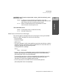
Chapter 112
Database Browser
The FactoryLink Database Browser task works in conjunction with the
FactoryLink Historian task to allow an application to access data in a relational
database through a browse window. Browser offers the following features:
• Allows relational data in a relational database to be manipulated from within
FactoryLink
• Allows an application to send and retrieve data to and from all external
database tables, including those created outside of FactoryLink
• Allows you to define elements referenced by Browser in arrays as well as
individually
OF
O PERATION
Browser is a Historian-client task that communicates with Historian through
mailbox elements to send and receive historical information stored in an external
database.
Browser accesses data in a relational database by selecting the data specified in a
configuration table and placing it in a temporary table called a result table. The
element views and modifies the data in the result table through a browse window.
A browse window is a sliding window that maps data between the relational
database and the real-time database. The browse window views selected portions
of the result table.
U SE
OF
L OGICAL E XPRESSIONS
You use logical expressions to specify the data in a relational database to view or
modify. For the purposes of Browser, a logical expression is a command containing
a standard Structured Query Language (SQL) WHERE clause. To make a logical
expression flexible at run time, use the name of an element whose value is a
WHERE clause. If viewing all data from a column in a relational database table,
you do not need to specify a logical expression.
You must know how to write a standard SQL statement to configure Browser. See
any SQL guide, such as Quick Reference Guide to SQL and/or the user manual for
the relational database in use for information about writing SQL statements.
FactoryLink 6.5.0 / Reference Guide / 29
Database Browser
P RINCIPLES
112
•
DATABASE BROWSER
•
Configuring Program Arguments
•
•
To select data from a database table, a logical expression works in conjunction
with the table’s column name and logical operators to form an SQL WHERE
clause. The WHERE clause specifies which rows in a database table to place in the
result table.
Browser performs four operations:
• Select
• Update
• Insert
• Delete
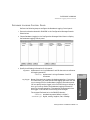
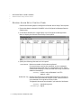
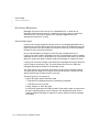
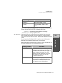
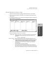
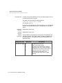
C ONFIGURING P ROGRAM A RGUMENTS
Configure the following system configuration program arguments to affect
Database Browser functionality:
-L or -l
-N or -n
Enables logging of errors to the log file. By default, the Database
Browser does not log errors.
Notifies on the completion of a SELECT trigger that the query
resulted in an End of Fetch condition if the rows returned from
the query do not equal the rows defined in the View Size. By
default, the Database Browser task does not report an End of
Fetch condition for a SELECT until a move operation advances
the current row past the last row of the query.
-S[4-160] or
-s[4-160]
Sets the maximum number of SQL statements that the Database
Browser will have active at one time. The default is 160. For very
large applications, this program switch may have to be adjusted if
the database server is unable to allocate a resource to open a new
SQL cursor.
-V1 or -v1
Writes the SQL statements generated by the Database Browser
to the log file. The Database Browser must have logging enabled
for this program switch to work. The default is to not write the
SQL statements to the log file.
-W[5-300] or
-w[5-300]
Sets the maximum timeout in seconds for the Database Browser
to wait for a response from the Historian task. The default is 30
seconds.
30 / FactoryLink 6.5.0 / Reference Guide
DATABASE BROWSER
Configuring Program Arguments
For values less than 30 seconds, this switch will only work
correctly when the Historian initially achieved a successful
connection with the database server. If the Historian failed to
successfully connect with the database server, Database Browser
will timeout in 30 seconds regardless of this switch setting.
112
Database Browser
FactoryLink 6.5.0 / Reference Guide / 31
•
DATABASE BROWSER
•
Database Browser Control Panel
•
•
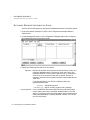
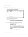
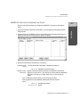
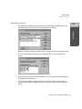
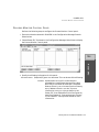
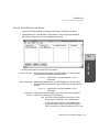
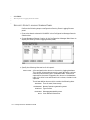
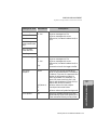
D ATABASE B ROWSER C ONTROL P ANEL
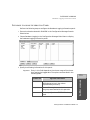
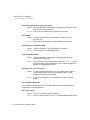
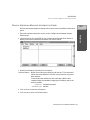
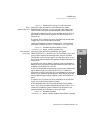
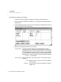
Perform the following steps to configure the Database Browser Control panel:
1 Ensure the domain selected is USER in the Configuration Manager Domain
Selection box.
2 Choose Database Browser in the Configuration Manager Main Menu to display
the Database Browser Control panel.
3 Specify the following information for this panel:
Browse Name
Alphanumeric string of 1 and 15 characters that specifies the
developer-assigned name of the browse window being defined or
modified.
Valid Entry: alphanumeric string of 1 and 15 characters
Select Trigger
Name of an element that triggers a select operation. A select
operation selects specific data from a relational database table
based upon information specified in the Database Browser
Information panel and places it in a result table for you to view or
manipulate.
A Tag Definition dialog is displayed when you click on Enter. Select
the appropriate data type if the tag specified in this field is
undefined.
Valid Entry: standard tag name
Valid Data Type: digital, analog, longana, float, message
32 / FactoryLink 6.5.0 / Reference Guide
DATABASE BROWSER
Database Browser Control Panel
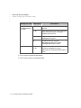
Update Trigger
Name of an element that triggers an update operation. Browser
performs a positional update if you defined a select trigger. When
the value of this element changes during a positional update,
Browser reads the values in the active row (the value of the
current row tag) and updates the values in that row of the result
table and external database.
In order for a positional update to work, the database table must
have a unique constraint configured for it; that is, a unique index
must exist for the database table. This can be configured in
Database Schema Creation or executed externally to FactoryLink
whenever the database table is created. Refer to Database
Logging for more information on configuring the Database
Schema Creation panel. Consult the RDBMS user’s manual if you
need to create a unique index on the database table that already
exists.
Valid Entry: standard tag name
Valid Data Type: digital, analog, longana, float, message
Delete Trigger
Name of an element that triggers a delete operation. Browser
performs a positional delete if you defined a select trigger.
Browser deletes the active row in the browse window from the
result table and external database when the value of this element
changes during a positional delete.
In order for a positional delete to work, the database table must
have a unique constraint configured for it; that is, a unique index
must exist for the database table. This can be configured in
Database Schema Creation or executed externally to FactoryLink
whenever the database table is created. Refer to Database
Logging for more information on configuring the Database
Schema Creation panel. Consult the RDBMS user’s manual if you
need to create a unique index on the database table that already
exists.
Browser performs a logical delete if you have not defined a select
trigger. Browser deletes the rows in the relational database
indicated by the logical expression during a logical delete.
Valid Entry: standard tag name
FactoryLink 6.5.0 / Reference Guide / 33
112
Database Browser
Browser performs a logical update if you have not defined a select
trigger to select specific data. During a logical update, Browser
reads the values in the first row of the browse window and uses
the logical expression defined in the Database Browser
Information panel to update the values in the external database.
•
DATABASE BROWSER
•
Database Browser Control Panel
•
•
Valid Data Type: digital, analog, longana, float, message
Move Trigger
(Requires use of the Select Trigger.) Name of an element that
moves the active row up or down the indicated number of rows.
The window scrolls the remaining number of records if the active
row reaches the first or last record in the browse window. For
example, if the value of the Move Trigger element is -3 and the
active row is positioned on the first row displayed in the browse
window, the data in the window scrolls down three rows.
Move operations can be performed only on result tables;
therefore, move operations cannot be performed unless you have
defined and executed a Select Trigger.
Valid Entry: standard tag name
Valid Data Type: analog
Position Trigger
(Requires use of the Select Trigger.) Name of an element that
moves the browse window to the specified row in the result table.
The specified row is centered in the browse window and becomes
the active row. For example, if the value of this element is 42, the
browse table displays row 42 of the result table.
Position operations are performed only on result tables; therefore,
position operations cannot be performed unless you define and
execute a Select Trigger.
Valid Entry: standard tag name
Valid Data Type: analog
Historian Mailbox
Name of a mailbox element whose value initiates communication
with an external database. Browser sends requests for
information from the relational database to this mailbox element.
The Historian task reads this element and transfers the request
to the external database.
Valid Entry: standard tag name
Valid Data Type: mailbox
Database Table
Name
Alphanumeric string of 1 and 63 characters that specifies the
Database Alias Name (defined in the Historian task) and the
name of the table in the relational database Browser requests
information from. Place a “.” between the Database Alias Name
and the Table Name.
Valid Entry: alphanumeric string of 1 and 63 characters
34 / FactoryLink 6.5.0 / Reference Guide
DATABASE BROWSER
Database Browser Control Panel
Current Row Tag
Name of an element whose value indicates the position of the
active row of data in a browse window. After Browser performs a
Select, Move, or Position operation, Browser writes the value
indicated by the position of the active row to this element.
Browser performs all update and delete operations on the row
indicated by the Current Row Tag element if you have defined a
select trigger.
Valid Entry: standard tag name
Valid Data Type: analog
Auto Create
Record
Indicates whether a new row is to be inserted in a database table
if a row cannot be found when an update operation is being
attempted. This feature works with logical updates but not with
positional updates. This can be one of the following:
YES Insert a new row of data.
NO Do not insert any new rows. This is the default.
Number between 1 and 50 characters that specifies the number of
rows in a browse window that can be viewed or modified. The
browse window size must be the same size as the element array
specified in the Tag Name field of the Database Browser
Information panel. All element arrays specified in the Tag Name
field must be the same size. The browse window size must be the
same as the size of the smallest element array if all element
arrays are not the same size. The Browse Table Size (Rows) field
also specifies the number of rows of data sent to Browser each
time Browser requests data from an Historian.
For example, the number specified in this field is 1. Enter a large
positive value in the Move Trigger or Position Trigger field to scroll
directly to the end of the result table. Because only one row of
data is being requested at a time, the operation or a large result
table takes more time than if the value in this field is larger.
Valid Entry: number between 1 and 50 characters
Internal Buffer Size
(Rows)
Number between 0 and 9999 that specifies the number of rows of
data in a result table that can be stored in memory.
Use the following guidelines to choose appropriate internal and
external buffer sizes.
Do not use a larger internal buffer than is needed because
memory is limited.
FactoryLink 6.5.0 / Reference Guide / 35
Database Browser
Browse Table Size
(Rows)
112
•
DATABASE BROWSER
•
Database Browser Control Panel
•
•
Calculate the length of each row in the result table as well as the
number of rows in the internal buffer to determine the amount of
memory required.
Browser operates more quickly if all rows in a result table are
stored in the internal buffer as opposed to being stored in the
external buffer.
Use a value large enough to contain as many rows as necessary
but small enough not to use up too much memory. If the size of
the result table is unknown and if memory allows, we recommend
you enter 100; however, if the result table will be shorter, enter a
number equalling (n)-(element array size) where n is the number of
rows in the result table.
The overflow is stored in the external buffer if you choose to store
only a given number of rows in the internal buffer and the result
table grows larger than the internal buffer.
If:
the internal buffer can store 25 rows
and
the external buffer can store an unlimited
number of rows
and
the browse window has 5 rows
and
then:
the result table contains 50 rows,
5 rows display in the browse window
and
25 rows are stored in the internal buffer
and
50 rows are stored in the external buffer
Valid Entry: numeric value of up to 9999
36 / FactoryLink 6.5.0 / Reference Guide
DATABASE BROWSER
Database Browser Control Panel
External Buffer
Size (Rows)
Completion Trigger
This field is not currently in use.
Name of an element whose change-status flag is set whenever
any browse operation for this browse window is complete.
Valid Entry: standard tag name
Valid Data Type: digital, analog, longana, float, message
Completion Status
Name of an element whose value indicates the status of the
current operation completed by the Browser or Historian. The
status is displayed as a character string if this element is of
message data type; otherwise, it displays as a numeric code. Refer
to “Database Browser Status Codes and Status Messages” on
page 45 for the codes and messages that can display in this tag.
You can configure this element to work in conjunction with output
objects in the Application Editor task to display codes or
messages on any graphics screen. Refer to the FactoryLink ECS
Application Editor for information about defining output objects.
Valid Entry: standard tag name
Valid Data Type: digital, analog, longana, float, message
4 Click on Enter to save the information.
5 Click on Exit to return to the Main Menu.
FactoryLink 6.5.0 / Reference Guide / 37
Database Browser
You can also configure Math & Logic to monitor this element and
respond to or ignore errors that occur.
112
•
DATABASE BROWSER
•
Database Browser Information Panel
•
•
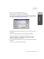
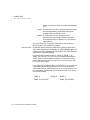
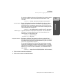
D ATABASE B ROWSER I NFORMATION P ANEL
Perform the following steps to configure the Database Browser Information panel:
1 Ensure the domain selected is USER in the Configuration Manager Domain
Selection box.
2 Choose Database Browser in the Configuration Manager Main Menu to display
the Database Browser Information panel.
3 Specify the following information for this panel:
Tag Name
Name of an element that contains the values from a column of a
relational database table. If the Browse Table Size field in the
Database Browser Control panel is greater than 1, the element
must be an array of Browse Table Size or greater. Ensure all
elements entered in the Tag Name field can accommodate Browse
Table Size.
If the tag specified in this field is undefined, select the
appropriate data type.
Valid Entry: standard tag name
Valid Data Type: digital, analog, longana, float, message
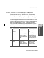
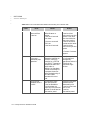
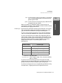
Logical Operator
Part of a WHERE clause that specifies the conditions Browser
uses to select rows from a relational database table. This field
works in conjunction with the Column Name and Logical Expression
fields (described below) to specify WHERE clauses. This can be
one of the following:
38 / FactoryLink 6.5.0 / Reference Guide
DATABASE BROWSER
Database Browser Information Panel
AND Specifies a combination of conditions in a logical
expression.
OR Specifies a list of alternate conditions in a logical
expression.
FactoryLink performs a sequential search through the database
even if the columns are indexed if you use the OR operator in a
logical expression when using the Historian for dBASE IV. This
may result in a slower response time if the database is large;
therefore, we recommend you not use OR operators in logical
expressions so the Historian for dBASE IV can take advantage of
indices.
NOT Negates a condition in a logical expression.
AND_NOT Specifies a combination of conditions and negated
conditions in a logical expression.
112
OR_NOT Specifies a list of alternate negated conditions in a
WHERE clause
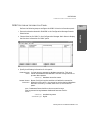
Column Name
Description
Col2 = 3 AND Col4 > 4
In this example, Database
Browser selects all rows where
Col2 is equal to 3 AND Col4 is
greater than 4.
Col3 < 6 OR Col2 >= 19
In this example, Database
Browser selects all rows where
Col3 is less than 6 OR Col2 is
greater than or equal to 19.
Col4 > 7 AND_NOT Col4 =
20
In this example, Database
Browser selects all rows where
Col4 is greater than 7 AND_NOT
equal to 20.
Alphanumeric string of 1 and 63 characters that specifies:
FactoryLink 6.5.0 / Reference Guide / 39
Database Browser
logical expression. (See examples in the following
table.)
•
DATABASE BROWSER
•
Database Browser Information Panel
•
•
(1) Character string representing the relational database column
name associated with the Tag Name element. The Column Name
field works in conjunction with the Logical Operator and Logical
Expression fields to specify WHERE clauses with the following
format:
([table.]column)
where
table Is the relational database table name. Include
table, if the table name is different from the table
name specified in the Database.Table Name field in
the Database Browser Control panel.
column Is the name of the column within the relational
database table. Use the same column name in two
rows of a panel.
OR
(2) SQL function, such as MAX (col_name) or COUNT (*). The
result of this function is written to the element specified in the
Tag Name field. SQL functions are supported only in SELECT
statements. SQL functions are not supported in UPDATE
statements or by the Historian for dBASE IV.
Valid Entry: alphanumeric string of 1 and 63 characters
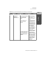
Logical Expression
Conditional statement that restricts the rows selected, updated,
or deleted from a database table. This field works in conjunction
with the Column Name and Logical Operator fields to generate the
WHERE clause used by the SQL statement.
Note: An embedded variable in Database Browser is a
FactoryLink element that is preceded by a colon. The embedded
variable can only be used in the Logical Expression field. The
embedded variable can be any FactoryLink element type except
mailbox. If the element is an array specify the dimension (for
example, :tag_xyz[2] ). The element in the embedded variable
is not detected by Configuration Manager as a tag, therefore
user must define the tag somewhere else in the application such
as in Math & Logic.
40 / FactoryLink 6.5.0 / Reference Guide
DATABASE BROWSER
Database Browser Information Panel
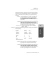
The conditional statement in a Logical Expression field can consist
of relational operators. The following is a list of relational
operators that are supported by the dBASE IV Historian.
is equal to
<
is less than
>
is greater than
<>
is not equal to
<=
is less than or equal to
>=
is greater than or equal to
is not
null
is not a null value (for dBASE IV
Historian TRUE when database
column is not all spaces)
between
X and Y
defines a range of values where X
is the lower limit and Y is the
higher limit. This is equal to
COLNAME >= X and
COLNAME <= Y
If using the dBASE IV Historian limit the logical expressions to
this list of relational operators. If not using dBASE IV Historian,
consult the RDBMS SQL Language user’s manual for more
information.
The WHERE clause is generated by appending the Local Operator,
Column Name, and Logical Expression fields in the order displayed
in the Database Browser Information panel. Punctuation is
supplied by the Database Browser to ensure correct SQL syntax.
Any embedded variable found in the Logical Expression field is
replaced by a ?, which SQL defines as a substitution marker for a
value to be supplied at execute time. The value supplied is the
tag’s value defined by the embedded variable.
The string generated by this is a WHERE condition. If the first
word(s) in this string is not an SQL reserved word such as
ORDER BY, then the reserved word WHERE is attached to the
start of this string. The user must ensure that any placement of
FactoryLink 6.5.0 / Reference Guide / 41
112
Database Browser
=
•
DATABASE BROWSER
•
Database Browser Information Panel
•
•
SQL clauses such as ORDER BY and GROUP BY is properly
ordered as defined by the SQL language for the targeted database
server.
The ORDER BY clause is supported in the dBASE IV Historian
but only to the extent that the columns listed in the ORDER BY
clause must match an index that was created for the database
table. The dBASE IV Historian does not build any temporary
tables to reorder the rows so make sure the ORDER BY matches
an index for the dBASE IV database table. If an ORDER BY
clause does not match an index, the dBASE IV Historian returns
an error.
If you define a Select Trigger in the Database Browser Control
panel, the WHERE clause is used for the selected statement. If a
Select Trigger is not defined, the WHERE clause is used for the
either the update operation or delete operation or both.
A Logical Expression can contain one of the following:
1. Character string of up to 79 characters containing an SQL
expression or an SQL clause.
For example, an SQL expression:
OUTLETVAL = 30 and TANKID = ‘BLUE001’
For example, an SQL clause:
ORDER BY TANKID
2. Character string of up to 79 characters representing an SQL
expression that contains embedded variables. If the element is a
message tag, the character data in the message tag should not be
enclosed in single quotes.
For example:
=:tagTANKID
WHEREtagTANKID is a message tag of
value: BLUE001
3. An embedded message variable only. THis variable must be a
message element. The message element contains an SQL clause
or SQL expression. THe SQL expression cannot contain an
embedded variable and any string constants in the SQL
expression must be quoted in single quotes.
For example:
:tagSQLExpression
WHEREtagSQLExpression is a message tag
42 / FactoryLink 6.5.0 / Reference Guide
DATABASE BROWSER
Database Browser Information Panel
OUTLETVAL = 30 and
TANKID = ‘BLUE001’
Note: Options 1 and 3 are different. The result is the same for
both options but option 3 allows the user to change the
tagSQLExpression element to a different expression before
setting a select, update, or delete trigger there by altering the
rows selected, updated, or deleted. Option 1 is always static and
cannot be changed at run time. Option 2 allows the user to
change the value of tagTANKID but the SQL expression is still
the same just the search criteria for the where clause has
changed.
The Database Browser substitutes embedded variables with the
value of the tag defined in the embedded variable when executing
the select, update, or delete SQL statement.
112
For example:
=:tagTANKID
TANKID is the value of the Column Name field.
The Database Browser reads the value of the element
tagTANKID from the real-time database and substitutes its
value for the ? whenever it executes a select, update, or delete
SQL statement.
FactoryLink 6.5.0 / Reference Guide / 43
Database Browser
generates the following WHERE clause:
WHERE TANKID = ?
•
DATABASE BROWSER
•
Database Browser Information Panel
•
•
The panel resembles the following sample panel when complete.
Because the Select Trigger element SELTAG1 (defined in the Control panel) is
digital in this example, the Historian returns the two following values to Browser
when the change-status flag for SELTAG1 is set:
• Values where the column named TANKID equals BLUE001
• The column named OUTLET is greater than or equal to the value of the
element OUTLETVAL.
Browser writes these values to the elements contained in the element arrays
TANKID[3] and OUTLET[3]. These values are then displayed in a browse window.
Each Tag Name element displays one column of values in a browse window.
Because a Tag Name element array has been defined for TANKID and OUTLET, the
values in the columns the logical expression is true for is displayed in the browse
window.
4 Click on Enter to save the information.
5 Click on Exit to return to the Main Menu.
44 / FactoryLink 6.5.0 / Reference Guide
DATABASE BROWSER
Database Browser Status Codes and Status Messages
D ATABASE B ROWSER STATUS C ODES
AND
S TATUS M ESSAGES
Whenever an error occurs at run time in the Browser, the Historian, or another
Historian-client task, FactoryLink sends a status code or status message for
display to the Run-Time Manager screen and to the completion status tag.
FactoryLink also sends a longer, more descriptive message to the log file if you
created a log file. This section describes the error messages that can be displayed
on the Run-Time Manager screen for the Browser task.
The codes and messages are displayed on a graphics screen if you define an output
text object to display them.
The following table lists status codes written to a numeric Completion Status tag
defined in the Database Browser Control panel. The descriptive message is
written to a message Completion Status tag and may also be written to the Task
Message tag in the System Configuration panel. See “Historian Messages” on
page 258 for status codes that are less than 100. The Historian generates these
codes, and they are returned to Browser when an historian operation is executed.
Error
Cause
Action
100
Asynchronous
error from
Historian
function.
An SQL COMMIT
operation failed within
the Historian.
Consult the database
administrator for the
external database in
use.
101
Error from
Historian
function.
A syntax error may have
been made or information
may not have been
entered in a required
field in a configuration
table.
Correct the SQL
statement syntax error
by modifying the
Information panel for
the task receiving the
error. If the information
is correct, ensure the
database table exists.
102
No fields for
select.
The task is trying to
execute a select
operation, but no Tag
Name elements have
been defined to hold the
data from the select
operation.
Define some Tag Name
elements in the Tag
Name field in the
Database Browser
Information panel.
FactoryLink 6.5.0 / Reference Guide / 45
Database Browser
Code
112
•
DATABASE BROWSER
•
Database Browser Status Codes and Status Messages
•
•
Code
Error
Cause
Action
103
No fields for
insert.
The task is trying to
execute an insert
operation, but no Tag
Name elements have
been defined to hold the
data from the insert
operation.
Define some Tag Name
elements in the Tag
Name field in the
Database Browser
Information panel.
104
No fields for
update.
Task is trying to execute
an update operation, but
no Tag Name elements
have been defined to hold
the data from the update
operation.
Define some Tag Name
elements in the Tag
Name field in the
Database Browser
Information panel.
105
Update and
delete operations
not supported
with multi-table
view.
Update and delete
operations cannot be
performed when using
multi-table view.
Do not perform update
and delete operations
when using multi-table
view.
106
Cannot update
until select is
performed.
A select trigger is
defined but a select
operation has not
executed. Execute a
select operation before an
update operation.
Execute a select
operation and then
retry the update
operation.
107
Cannot delete
until select is
performed.
A select trigger is
defined but a select
operation has not been
executed. Execute a
select operation before a
delete operation.
Execute a select
operation and then
retry the delete
operation.
108
Cannot move until
select is
performed.
A select trigger is
defined but a select
operation has not been
executed. Execute a
select operation before a
move operation.
Execute a select
operation and then
retry the move
operation.
46 / FactoryLink 6.5.0 / Reference Guide
DATABASE BROWSER
Database Browser Status Codes and Status Messages
Code
Error
Cause
Action
109
This row of data
has been deleted.
A delete operation
attempted on a
nonexistant row
No action required.
110
A FactoryLink
function returned
an error.
FactoryLink PAK
function encountered an
unknown or unexpected
error.
Contact Customer
Support.
111
A file function
error occurred.
System encountered an
unknown error while
trying to read or write to
the external buffer.
If not enough space,
decrease the buffer
size. If there is enough
disk space, contact
Customer Support.
Bad tag in logical
expression.
Either a typographical
error exists or an
undefined or invalid
element name is entered
as an embedded variable
element in a Logical
Expression field.
Correct typographical
errors. If you did not
make a typographical
error, then define the
element in a
FactoryLink task other
than Browser.
113
Invalid use of tag
in logical
expression.
Logical expression does
not contain a valid
element name.
Correct typographical
errors and ensure the
element name is the
name of a valid
element.
114
HSDA structure
too small.
Invalid use of an element
in logical expression.
Define the element
used in the logical
expression in a
FactoryLink task other
than Browser.
115
Can’t open log file. Disk space too low.
If disk space is low,
delete unneeded files or
programs; otherwise,
contact Customer
Support.
FactoryLink 6.5.0 / Reference Guide / 47
Database Browser
112
112
•
DATABASE BROWSER
•
Database Browser Status Codes and Status Messages
•
•
Code
Error
Cause
Action
116
A request for
memory failed.
Internal error.
Contact Customer
Support.
117
Can’t find unique
index for table.
A positional update or
delete operation occurred
on a table without a
unique index.
Create a unique index
for the table and retry
the operation.
One of the following messages is displayed to the right of BROWSER on the
Run-Time Manager screen if an error occurs with Browser or Historian at run
time. The first three letters in the message are a variable that indicates whether
the message came from Browser (DBB) or the Historian (HIS). This variable
three-letter prefix displays in the messages below as nnn. Open the .LOG file to
display the complete message if truncated on the Run-Time Manager screen.
nnn -[BAD_SMBX] Bad send mailbox. Browse rec: browse window name
Cause:
You entered the wrong mailbox element name.
Action:
Look up the mailbox element name for the Historian being used
in the Historian Mailbox field of the Historian Mailbox Information
panel. Enter the correct name in the Historian Mailbox field of the
Database Browser Control panel.
nnn -[BAD_WHERE_TAG] Bad tag element name for logical expression. Browse
rec: browse window name
Cause:
Either you made a typographical error or entered an undefined
or invalid element name as the embedded message element in a
logical expression.
Action:
Correct all typographical errors. Define the element in a
FactoryLink task other than Browser if you did not make a
typographical error.
nnn -[CT_HDR] No sel, upd, or delete trigger defined. Browse rec: browse
window name
Cause:
None of the following triggers are defined:
- select
- delete
- update
48 / FactoryLink 6.5.0 / Reference Guide
DATABASE BROWSER
Database Browser Status Codes and Status Messages
Action:
Define at least one of the triggers listed above.
nnn -[DBTBL_SYNTAX] The Database Table value is missing a “.”. Browse rec:
browse window name
Cause:
You left the “.” out of the entry in the Database.Table Name field
in the Database Browser Control panel.
Action:
Put a “.” between the database name and the table name in the
entry in the Database.Table Name field.
nnn-[FILE_ERR] File function “function” returned error error code. Browse rec:
browse window name
Cause:
The system encountered an unknown error while trying to read
from or write to the external buffer.
Action:
Verify you have enough disk space. If not, decrease the buffer
size. Contact Customer Support if there is enough disk space.
Cause:
The FactoryLink PAK function encountered an unknown or
unexpected error.
Action:
Contact Customer Support.
nnn-[FL_FUNC] Function “FL_WRITE” returned error 9. Browse rec: browse
window name
Cause:
The column type in the database FactoryLink is trying to read
from does not match the column type defined in the Database
Logging task Schema Creation table.
Action:
Redefine the column type in the Column Type field of the Schema
Creation table to be the same as the column type in the
database.
nnn -[FLERROR] FactoryLink error error number
Cause:
An unknown PAK function error occurred within the Historian.
Action:
Contact Customer Support.
FactoryLink 6.5.0 / Reference Guide / 49
Database Browser
nnn -[FL_FUNC] Function “function” returned error error code. Browse rec:
browse window name
112
•
DATABASE BROWSER
•
Database Browser Status Codes and Status Messages
•
•
nnn-[HSCONNECT] Failed to connect to historian
Cause:
You may have specified the wrong mailbox element name.
Action:
Specify the Historian Predefined mailbox element name in the
Historian Mailbox field in the Database Browser Control panel.
nnn -[HSDA_TOO_SMALL] HSDA structure too small. Browse rec: browse
window name
Cause:
You specified an invalid element in a logical expression.
Action:
Define the element used in the logical expression in a
FactoryLink task other than Browser. The element will then be
valid in the logical expression.
nnn -[HSDBERROR] Historian database error: error message
Cause:
This message is accompanied by various other messages that
describe the cause of the error.
Action:
Read the accompanying message displayed on the Run-Time
Manager screen or in the .LOG file and attempt to correct the
problem based on the instructions in the message.
nnn -[HSDUPLICATE] Tried to insert a duplicate row
Cause:
You tried to insert a duplicate row into a result table.
Action:
No action required.
nnn -[HSENDOFETCH] Last row fetched or row not found
Cause:
The task could not find a row during an update operation
because that row does not exist. Or, during a move or position
operation, you specified a nonexistent row (for example, row 100
when the table has only 50 rows). You attempted to go past the
end or above the beginning of the result table.
Action:
No action required.
nnn -[HSFLDEXISTS] Tried to add an existing field
Cause:
You tried to add an existing field.
Action:
No action required.
50 / FactoryLink 6.5.0 / Reference Guide
DATABASE BROWSER
Database Browser Status Codes and Status Messages
nnn -[HSMAXOPENS] Too many open sessions
Cause:
You tried to open data from more than ten unique databases.
Action:
Reference fewer than ten unique databases in a configuration
table.
nnn -[HSMEMORY] Memory error malloc failed
Cause:
Not enough memory is allocated for the Historian.
Action:
Allocate more memory for the Historian.
nnn-[HSNOFIELD] Tried to access a nonexistent field
Cause:
You tried to open a nonexistent field.
Action:
No action required.
112
nnn -[HSNOTABLE] Tried to access a nonexistent table
You tried to open a nonexistent table.
Action:
No action required.
nnn -[HSPREPARE] Failed to prepare stmtid
Cause:
A nonexistent table name or field name is specified or a syntax
error is made in an SQL statement.
Action:
Ensure all entries in the Database Browser table are correct,
especially those for the SQL statement.
nnn -[HSSTMTID] Invalid stmtid returned from historian
Cause:
The Historian shut down before Browser or another
Historian-client task.
Action:
Shut down Browser and all other Historian-client tasks running
on the system. Then, shut down the Historian and restart it,
followed by Browser and all other Historian-client tasks running
on the system.
Cause:
An error occurred within Browser.
Action:
Contact Customer Support.
FactoryLink 6.5.0 / Reference Guide / 51
Database Browser
Cause:
•
DATABASE BROWSER
•
Database Browser Status Codes and Status Messages
•
•
nnn-[HSTBLEXISTS] Tried to create an existing table
Cause:
You tried to create an existing table.
Action:
No action required.
nnn -[HSUNKNOWN] Unknown function request sent to historian
Cause:
An error occurred within Browser.
Action:
Contact Customer Support.
nnn-[INVUSE_WHERE_TAG] Invalid use of tag in logical expression. Browse rec:
browse window name
Cause:
A logical expression contains an invalid element name.
Action:
Correct all typographical errors and ensure the element name is
the name of a valid element.
nnn -[MULTI-VIEW] Update and delete operations not supported with multi-table
view. Browse rec: browse window name
Cause:
You tried to perform an update or delete operation while using
multi-table view.
Action:
Do not try to perform update or delete operations.
nnn -[NO_FLDS_INS] No fields for insert. Browse rec: browse window name
Cause:
The task is trying to perform an insert operation but no Tag
Name elements are defined to hold the data from the insert
operation.
Action:
Define some elements in the Tag Name field of the Database
Browser Information panel.
nnn-[NO_FLDS_SEL] No fields for select. Browse rec: browse table name
Cause:
The task is trying to execute a select operation but no Tag Name
elements are defined to hold the data from the select operation.
Action:
Define some elements in the Tag Name field of the Database
Browser Information panel.
52 / FactoryLink 6.5.0 / Reference Guide
DATABASE BROWSER
Database Browser Status Codes and Status Messages
nnn -[NO_FLDS_UPD] No fields for update. Browse rec: browse table name
Cause:
The task is trying to execute an update operation, but no Tag
Name elements have been defined to hold the data from the
update operation.
Action:
Define some elements in the Tag Name field of the Database
Browser Information panel.
nnn -[NO_LOGICAL_EXPR] No logical expr. Browse rec: browse table name .
Column name: column name
Cause:
A logical operation was defined but the logical expression was
not specified.
Action:
Either delete the operation or create a logical expression.
nnn -[NO_MEMORY] Out of RAM
112
Not enough RAM is available to run this task.
Action:
Allocate more RAM for the Browser task.
nnn -[NOTASSOC] Col name column name not associated with browse or where
tag. Browse rec: browse window name
Cause:
A non-existent or an invalid Tag Name element is specified. A
column name is also specified but not a logical expression.
Action:
Define an element in the Tag Name field of the Database Browser
Information panel and/or specify a logical expression.
nnn -[NO_UNIQ_INDX] Can’t find unique index for table. Browse rec: browse
window name
Cause:
You attempted a positional update or delete operation on a table
without a unique index.
Action:
Create a unique index for the table and retry the operation.
nnn -[NULL_ROW] This row of data was deleted. Browse rec: browse window
name
Cause:
You attempted a delete operation on a deleted row.
Action:
No action required.
FactoryLink 6.5.0 / Reference Guide / 53
Database Browser
Cause:
•
DATABASE BROWSER
•
Database Browser Status Codes and Status Messages
•
•
nnn -[NULL_TABLE] No data for this table. Browse rec: browse table name
Cause:
You tried to perform an update, move, or delete operation on a
result table that contains no rows of data for either of two
reasons: the select operation resulted in no rows of data or you
deleted all rows of data from the table.
Action:
No action required.
nnn -[OPEN_LOG] Can’t open .LOG file.
Cause:
The computer may have run out of disk space.
Action:
Delete any unnecessary files or programs. Contact Customer
Support.
nnn -[SEL_B4_DEL] Can’t delete until select is performed. Browse rec: browse
window name
Cause:
You defined a select trigger but a select operation was not
executed. A select operation must be executed before a delete
operation can be performed.
Action:
Execute a select operation and then retry the delete operation.
nnn -[SEL_B4_MOVE] Can’t move until select is performed. Browse rec: browse
window name
Cause:
A select trigger is defined but a select operation was not
executed. A select operation must be executed before a move
operation can be performed.
Action:
Execute a select operation and then retry the move operation.
nnn -[SEL_B4_UPD] Can’t update until select is performed. Browse rec: browse
window name
Cause:
A select trigger is defined but a select operation was not
executed. A select operation must be executed before an update
operation can be performed.
Action:
Execute a select operation and then retry the update operation.
54 / FactoryLink 6.5.0 / Reference Guide
DATABASE BROWSER
Database Browser Status Codes and Status Messages
nnn -[SQL_ASYNC] Asynchronous failure to name . Error: error message.
Cause:
An SQL COMMIT operation failed within the Historian. For
Oracle, it can fail if you do not have enough disk space.
Action:
Consult the database administrator for the external database in
use.
nnn -[SQL_SYNC] Historian function function failed. Error: error message
Browse rec: browse window name
Cause:
A syntax error may have been made or there may not be any
information in a required field in a configuration table.
Action:
Modify the information in the Database Browser Information
panel to create a correct SQL statement if the error is a syntax
error. Ensure the database table exists if the panels are correct.
nnn -[UNSOL_MSG_RCVD] Unsolicited message received from element number
Another task wrote to Browser’s mailbox element (Browser is not
expecting to hear from this task).
Action:
Determine which task is writing to Browser’s mailbox element
by looking at the X-reference list in the Configuration Manager
Main Menu. Correct the problem by changing the mailbox
element name of the task writing to Browser’s mailbox element.
F_BAD_CT_SIZE Bad size for CT #(CT number)
Cause:
There is a discrepancy between the Browser script file and the
size. You may have modified the Browser .CTG file.
Action:
Copy the .CTG file from the Installation disk over the modified
one. Contact Customer Support if this is not the problem.
F_BAD_RMBX Invalid global mailbox: mailbox name
Cause:
Browser’s predefined mailbox element is nonexistent in the
GLOBAL.CT file.
Action:
Contact Customer Support.
FactoryLink 6.5.0 / Reference Guide / 55
Database Browser
Cause:
112
•
DATABASE BROWSER
•
Database Browser Status Codes and Status Messages
•
•
F_INIT Task initialization failed
Cause:
This message is preceded by another error message that explains
the cause of the error.
Action:
Examine the preceding message to determine the cause of the
initialization failure.
F_NO_CTS No valid tables in CT archive file name
Cause:
The Database Browser table is been configured.
Action:
Configure the Database Browser table.
F_NO-DOMAIN_NAME No domain name for appl. directory directory
Cause:
No domain name is specified for the application directory.
Action:
Specify a domain name for the application directory.
F_OPEN_CT Can’t open CT archive file name
Cause:
A .CT file may have been deleted.
Action:
Use CTGEN to rebuild the .CT file.
F_READ_CT Can’t read CT #CT number in CT archive file name
Cause:
A .CT file is corrupt.
Action:
Rebuild the corrupt .CT file.
56 / FactoryLink 6.5.0 / Reference Guide
•
•
•
•
Chapter 113
Database Logging
Data is stored as a data element in a real-time database as FactoryLink collects
and computes the data. Each time data is collected or computed, the new data
overwrites the element value stored in the real-time database.
Data can be logged to an historical database using Database Logging if data, such
as reports or information on trend charts, is to be preserved for historical
purposes. Database Logging reads data from the memory-based real-time
database and sends it to a disk-based relational database.
Logging sends data to a relational database via FactoryLink Historian. The
Historian used for this transfer depends on the relational database receiving the
data. This can be either the dBASE IV-compatible database that can be purchased
with FactoryLink or a third-party relational database, such as Oracle7 or Sybase.
Refer to “Historian Task Definition” in Fundamentals for details on which third
party relational databases are compatible with FactoryLink.
Database Logging Methodology
This section describes and illustrates how memory-resident real-time data is
logged to a disk-based relational database.
1. The real-time database receives and stores data from various sources, such as
a remote device, user input, or computation results from a FactoryLink task.
When data is collected and stored in this database, other tasks can access and
manipulate it.
3. Database Logging sends the data from the real-time database to an Historian
mailbox in the form of an SQL INSERT statement. The request remains in the
Historian mailbox until Historian processes the request.
Once Historian processes the request, it connects to the relational database and
inserts the data in the relational database file. Once in this file, other applications
can use the data.
FactoryLink 6.5.0 / Reference Guide / 57
Database Logging
2. Database Logging reads the values of data elements stored in the real-time
database and maps the data elements to columns in a disk-based relational
database table.
113
•
DATABASE LOGGING
•
•
•
You must consider the following when selecting a logging method:
Grouping Data:
Ordering Data
FactoryLink permits you to log data with or without a group
association. If you elect to log data without a group association
(nongrouped), the table delineates the data in the table from data
in other tables.
FactoryLink permits you to log grouped and nongrouped data
with or without a sequence or order number. If you elect to
associate a sequence number with rows of data, your table
structure must include a column that contains the sequence
number associated with the row of data (record). The sequence
number can be an integer or a time-stamping.
Indexing
Records are displayed in a relational database table in the order
they are added. This is known as the natural or physical order.
The field or fields selected for indexing are called the index
key.When a table is indexed, an index file is created that contains
the indexed order. The actual record order in the database file
remains unchanged. Accessing indexed records is faster than
accessing non-indexed records.
Deletion Methods
The logging method you choose depends in part on how data gets
deleted from the relational database. Your options include:
Record rollover
Subgroup rollover
Group data deletion
Database Logging
Methods
Available database logging methods include:
Nongrouped/Nonsequenced Method
Nongrouped/Sequenced Method
Grouped Method
Configuring
Program
Arguments
You configure system configuration program arguments to affect
Database Logging functions.
58 / FactoryLink 6.5.0 / Reference Guide
DATABASE LOGGING
Database Logging Control Panel
D ATABASE L OGGING C ONTROL P ANEL
Perform the following steps to configure the Database Logging Control panel:
1 Ensure the domain selected is SHARED in the Configuration Manager Domain
Selection box.
2 Choose Database Logging in the Configuration Manager Main Menu to display
the Database Logging Control panel.
3 Specify the following information for this panel:
Log Name
Alphanumeric string of between 1 and 16 characters to reference
the logging operation.
Valid Entry: alphanumeric string of between 1 and 16
characters
Name of the tag that triggers the logging operation. If you leave
this field blank, you must activate the logging operation with the
Log-On Change field in the Database Logging Information panel.
You can specify both a trigger in this field and a log on change in
the Log On Change field of the Database Logging Information
panel for the same operation. The operation executes each time
the trigger is set and each time the tag value changes.
The tag specified must be in the SHARED domain.
Valid Entry: standard tag name (default = digital)
Valid Data Type: digital, analog, longana, float, message
FactoryLink 6.5.0 / Reference Guide / 59
Database Logging
Log Trigger
113
•
DATABASE LOGGING
•
Database Logging Control Panel
•
•
Historian Mailbox
Name of the mailbox tag used to transfer the data to the
Historian. Define the connection for this mailbox in the Historian
table.
Refer to Chapter 120, “Historian,” for details on the strategy for
defining historian mailboxes.
Valid Entry: standard tag name
Valid Data Type: mailbox
Database Alias
Name
Database alias name that references the database where
Historian sends the data. Define the same alias name in the
Historian table when defining the mailbox connection.
Valid Entry: database alias name
Database Table
Name
Name of up to 31 characters to reference the table in the
relational database that receives the data. If this table does not
already exist in the relational database when data is logged to it,
it is created using the schema defined in the Schema Name field.
Valid Entry: name of up to 31 characters
Schema Name
Name assigned to the schema that defines the structure of the
relational database table that receives the data. If the table
specified in the Database Table Name field of this panel does not
already exist in the relational database when data is logged to it,
it is created using the schema defined in this field.
If you enter a name in this field, it must match a name defined in
the Schema Name field on the Schema Control panel. If it does not
match a defined schema name, it is as if you left this field blank.
If you leave this field blank and a table with the name defined in
the Database Table Name field on this panel does not exist in the
relational database, a table is not created and data is not logged.
Valid Entry: schema name
Priority
Number between 0 and 9 that controls the order Logging handles
the queueing of logging operations in. This is a relative priority to
other logging operations. For example, if Logging receives two
requests at the same time from two different operations, it
processes the request with the highest priority (lowest number)
first.
Valid Entry: number between 0 and 9 (default = 0)
60 / FactoryLink 6.5.0 / Reference Guide
DATABASE LOGGING
Database Logging Control Panel
Completion Status
Tag
Name of a tag that indicates the completion of this logging
operation. A 1 is written to this tag once data is logged to the
Historian mailbox. Do not specify a tag name if you do not want to
track the completion of this logging operation.
This field is typically used for coordinating activities between
tasks. That is, you can use the completion of this logging
operation to trigger another task or operation.
The tag specified must be in the SHARED domain.
Valid Entry: standard tag name (default = digital)
Valid Data Type: digital, analog, longana, float
Current Sequence
Tag
Name of the tag that stores the current sequence number for this
logging operation. The next time a logging operation occurs, the
value stored in this tag is incremented by 1, and the new value is
assigned to the row of data.
The tag specified must be in the SHARED domain.
The Current Sequence Tag value is saved in a file when
FactoryLink is not running and updated to this field when
FactoryLink is restarted so interrupts do not cause problems with
duplicate records in the relational database table.
Valid Entry: standard tag name (default = longana)
Valid Data Type: analog, longana, float
Sequence Change
Tag
Name of the tag used to adjust the numbering sequence during
run time when ordering data by integer. This field provides the
ability to manually create gaps in the numbering sequence of
ordered data.
If you leave this field blank, you can never manually adjust the
numbering sequence of ordered data.
The tag specified must be in the SHARED domain.
If the tag type is digital, increment the Current Sequence Tag by 1
by force writing a 1 to the Sequence Change Tag.
FactoryLink 6.5.0 / Reference Guide / 61
Database Logging
When a value is force written to the tag specified in this field, the
value written is used to adjust the Current Sequence Tag value.
For example, if the Current Sequence Tag value is 5 and you force
write a value of 5 to this tag, the Current Sequence Tag changes to
10.
113
•
DATABASE LOGGING
•
Database Logging Control Panel
•
•
If the tag type is analog, long analog, or floating-point, you can
force write any whole positive or negative number to the
Sequence Change Tag. If you write a positive number, the value of
the Current Sequence Tag increments by the specified number. If a
negative number is written, the value of the Current Sequence Tag
decrements by the specified number.
Be careful when adjusting the Current Sequence Tag by a negative
number as this can cause two rows of data to have the same
sequence number. If the sequence number is part of a unique
index, duplicate record values are not permitted in the column.
FactoryLink displays an error message and the data is not logged
if an attempt is made to log a duplicate value.
Valid Entry: standard tag name (default = digital)
Valid Data Type: digital, analog, longana, float
Group Delete Tag
Name of a tag that contains the name of the group to delete when
the Group Delete Trigger tag executes. When group deletion is
triggered, all data for the group is deleted. If the group contains
subgroups, all subgroups and their data are deleted.
If you do not specify a tag in this field, you can never delete data
by specifying a group name.
If you do not specify a tag in this field but do specify a Group
Delete Trigger, when the trigger executes, all nongrouped data
sequenced by integer and all subgroups without a groupname
association are deleted for the table.
The tag specified must be in the SHARED domain.
If groupname is numeric, valid types are digital, analog, long
analog, or floating-point.
If groupname is made up of characters, valid type is message.
Enter the name of the group to delete in the Value field of the Tag
Definition dialog.
Valid Entry: standard tag name
Group Delete
Trigger
Name of the tag that triggers the deletion if you want to delete
data by group based on an event. When this trigger is set, the
data for the group specified in the Group Delete Tag field on this
panel is deleted. If you leave this field blank, deletion of group
data is never triggered.
The tag specified must be in the SHARED domain.
62 / FactoryLink 6.5.0 / Reference Guide
DATABASE LOGGING
Database Logging Control Panel
Leave the Group Delete Tag and Group Delete Trigger fields blank if
you are subgrouping data without a group association. If you wish
to delete subgroup data without a group association, use the
subgroup rollover feature.
Valid Entry: standard tag name (default = digital)
Valid Data Type: digital, analog, longana, float
Current
Subgroup Tag
Name of the tag that stores the current subgroup number for this
group.
The next time a new subgroup is created for this group, the value
stored in this tag is adjusted by the amount defined in the
Subgroup Change Tag field on this panel and assigned to the new
subgroup.
If this field is left blank, subgroups are not supported for this
group and no subgroups are created for this group.
The value of this tag is set to 0 at group delete and 1 at subgroup
rollover.
The tag specified must be in the SHARED domain and either
analog, long analog, or floating-point. The default is long analog.
The Current Subgroup Tag value is saved in a file when
FactoryLink is not running and updated to this field when
FactoryLink is restarted so interrupts do not cause problems with
duplicate records in the relational database.
Valid Entry: standard tag name (default = longana)
Valid Data Type: analog, longana, float
Subgroup Change
Tag
If this field is left blank, subgroups are not supported for this
group and no subgroups are created for this group.
If you enter a tag name in this field, a tag must also be defined in
the Current Subgroup Tag field.
The tag specified must be in the SHARED domain.
If the tag type is digital, the Current Subgroup Tag increments by
1 when 1 is force-written to this tag.
FactoryLink 6.5.0 / Reference Guide / 63
113
Database Logging
Name of the tag that triggers a subgroup change. When the value
of this tag changes, a new subgroup is created. The value to
assign to the new subgroup is calculated by adjusting the value in
the Current Subgroup Tag by the value in the Subgroup Change Tag.
This field provides the ability to manually set or change the
subgroup numbering sequence.
•
DATABASE LOGGING
•
Database Logging Control Panel
•
•
If the tag type is analog, long analog, or floating-point, force-write
any whole positive or negative number to this tag. If it contains a
positive number, the value in the Current Subgroup Tag increments
by the specified number. If it contains a negative number, the
value of the Current Subgroup Tag decrements by the specified
number.
Be careful when adjusting the Current Subgroup Tag by a negative
number as this can cause two subgroups to have the same
number. If the group ID is part of a unique index, duplicate record
values are not permitted in the column. If an attempt is made to
log a duplicate value, FactoryLink displays an error message and
the data is not logged.
Leave this field blank to use the same subgroup number each
time this trigger executes.
Valid Entry: standard tag name (default = digital)
Valid Data Type: digital, analog, longana, float
Maximum
Subgroups
Number to indicate the maximum number of subgroups allowed
before subgroup rollover occurs. If you leave this field blank, but
have specified a subgroup tag, Logger continues to increment the
subgroup number indefinitely until the disk is full.
If this field is left blank, subgroups are not supported for this
group and no subgroups are created for this group.
Define a tag in the Current Subgroup Tag field for subgroup
rollover to occur.
4 Click on Enter to save the information.
5 Click on Exit to return to the Main Menu.
64 / FactoryLink 6.5.0 / Reference Guide
DATABASE LOGGING
Database Logging Information Panel
D ATABASE L OGGING I NFORMATION P ANEL
Perform the following steps to configure the Database Logging Information panel:
1 Ensure the domain selected is SHARED in the Configuration Manager Domain
Selection box.
2 Choose Database Logging in the Configuration Manager Main Menu to display
the Database Logging Information panel.
3 Specify the following information for this panel:
Tag Name
Entry in this field depends on the column usage of the column
that receives the logged data. The options are described in the
following table.
113
Column Use
Tag Name Field Value
Tag name that references the real-time
data element to log in the column
represented by this entry.
group
Name of the tag that contains the name of
the group associated with this operation.
time
Do not specify a time. SECTIME is always
used.
FactoryLink 6.5.0 / Reference Guide / 65
Database Logging
data
•
DATABASE LOGGING
•
Database Logging Information Panel
•
•
Column Use
sequence
Tag Name Field Value
If you want to manually set the sequence
number to use for the next logging
operation, name of the tag that contains
the absolute number you want to use. If
you never want to manually set the
sequence number, leave this field blank.
If this tag value is any number except
zero, that number is assigned as the
sequence number for the next row of data
logged. Then this tag value is reset to zero.
If a record with that sequence number
already exists and the sequence number is
part of a unique index, data is not logged.
If this tag value is zero, the next sequence
number assigned to a row of data logged is
the value in the Current Sequence Tag field
after it is incremented by 1.
This operation does not update the Current
Sequence Tag field. The next sequence
number assigned continues from the
number in the Current Sequence Tag field.
The tag specified must be in the SHARED domain. The valid type
depends on the column usage. The options are described in the
following table.
Column Usage
Valid Tag Types
data
Digital, analog, floating-point, message,
or long analog.
sequence
Analog, floating-point or long analog.
time
The global tag SECTIME is already
defined. You do not have to specify a
type.
66 / FactoryLink 6.5.0 / Reference Guide
DATABASE LOGGING
Database Logging Information Panel
Column Usage
group
Column Name
Valid Tag Types
If groupname is numeric, use digital,
long analog, analog, or floating-point.
If groupname is made up of characters,
use message.
Name of the column to receive the data. Enter the name of the
column to receive the data.
If the table structure is defined through the relational database
software, the name must match one of the columns defined for the
table.
If the table structure is defined through FactoryLink, the name
must match one of the column names defined in the Column Name
field on the Schema Information panel.
Max. Msg. Length
If the data logged to this column is of type message, number
between 1 and 999 to specify the maximum number of characters
allowed in this column. If you leave this field blank when the tag
type is message, the default is 80. The value specified in this field
should always be equal to or less than the value specified in the
Length or Precision field on the Schema Information panel.
For tags defined with a tag type other than message, leave this
field blank to assume the default of 0 (zero), which indicates this
field is not used.
Log On Change
Specifies whether or not the logging operation is triggered if the
value for the tag specified in the Tag Name field of this panel
changes. This can be one of the following:
in this field for at least one tag on this panel to
activate the logging operation.
NO The log operation does not occur when the tag
value changes. Specify NO if you do not want a
change in this tag value to cause a log operation to
occur.
FactoryLink 6.5.0 / Reference Guide / 67
113
Database Logging
YES The log operation occurs when the tag value
changes. If you leave the Log Trigger field blank on
the Database Logging Control panel, indicate YES
•
DATABASE LOGGING
•
Database Logging Information Panel
•
•
Specify both a trigger in the Log Trigger field of the Database
Logging Control panel and a log on change in this field for the
same operation. The operation executes each time the trigger is
set and each time the value specified changes.
Column Usage
Kind of information sent to the column. This can be one of the
following:
data Use for columns that do not receive a sequence
number or group ID.
sequence Use for columns receiving a sequence number in
the form of an integer.
time Use for columns receiving a sequence number in
the form of a time-stamping. The time-stamping
used is SECTIME.
group Use for columns receiving the group identification
assigned to the row of data.
Data is assumed if you leave this field blank, even though the
word data is not displayed in the field.
The value entered must match the value entered for this column
in the Column Usage field on the Schema Information panel if the
table structure is defined with FactoryLink.
4 Click on Enter to save the information.
5 Click on Exit to return to the Main Menu.
68 / FactoryLink 6.5.0 / Reference Guide
DATABASE LOGGING
Database Logging Messages
D ATABASE L OGGING M ESSAGES
An error message is displayed on the Run-Time Manager screen next to the name
of the Logging task on the SHARED domain window if any problems are
encountered by Database Logging during run time.
Following is a list of all messages that can occur during Database Logging run
time with possible causes and corrective actions.
Bad activation trigger in Log name: logname
Cause:
An invalid activation trigger exists in the DBLOG.CT file.
Action:
Verify the data type of the tag that triggers the logging operation
specified by logname is a valid type where logname is the name
designated for the control entry. Logging operation triggers are
specified in the Log Trigger field of the Database Logging Control
panel. Only digital, analog, long analog and floating-point types
are valid. If incorrect, delete the tag, recreate it with a valid data
type, and then restart the application.
Bad Completion trigger in Log name: logname
Cause:
An invalid completion trigger exists in the DBLOG.CT file.
Action:
Verify the data type of the tag that identifies the completion of
the logging operation specified by logname is a valid type where
logname is the name designated for the control entry. Logging
completion triggers are specified in the Completion Status Tag
field of the Database Logging Control panel. Only digital, analog,
long analog and floating-point types are valid. If incorrect, delete
the tag, recreate it with a valid data type, and then restart the
application.
Cause:
The Current Sequence tag has an invalid data type for the
logging operation specified by logname.
Action:
Verify the data type for the Current Sequence Tag on the
Database Logging Control panel is digital, analog, long analog,
or floating-point. If incorrect, delete the tag, recreate it with a
valid data type, and then restart the application.
FactoryLink 6.5.0 / Reference Guide / 69
Database Logging
Bad current sequence tag in Log name: logname
113
•
DATABASE LOGGING
•
Database Logging Messages
•
•
Bad current subgroup tag in log name: logname
Cause:
The Current Subgroup Tag has an invalid data type for the logging
operation specified by logname.
Action:
Verify the data type for the Current Subgroup Tag on the Database
Logging Control panel is digital, analog, long analog, or
floating-point. If incorrect, delete the tag, recreate it with a valid
data type, and then restart the application.
Bad field type in schema name: schemaname , field name fieldname
Cause:
The Column Type field on the Schema Information panel is blank
and data is defined in the Column Usage field.
Action:
Ensure the Column Type field and Column Usage fields of the
Schema Information panel are compatible.
Bad group delete tag in log name: logname
Cause:
The Group Delete Tag has an invalid data type for the logging
operation specified by logname.
Action:
Verify the data type for the Group Delete Tag on the Database
Logging Control panel is digital, analog, long analog,
floating-point, or message. If incorrect, delete the tag , recreate it
with a valid data type, and then restart the application.
Bad group delete trigger in log name: logname
Cause:
The Group Delete Trigger has an invalid data type for the logging
operation specified by logname.
Action:
Verify the data type for the Group Delete Trigger on the Database
Logging Control panel is digital, analog, long analog,
floating-point, or message. If incorrect, delete the tag, recreate it
with a valid data type, and then restart the application.
Bad log records in log name: logname
Cause:
A field name that requires an entry is blank for the logging
operation specified by logname.
Action:
Verify all field entries in the Database Logging Control and
Database Logging Information panels have valid entries.
70 / FactoryLink 6.5.0 / Reference Guide
DATABASE LOGGING
Database Logging Messages
Cause:
The Tag Name field has an invalid data type for the logging
operation specified by logname.
Action:
Verify the data type for the Tag Name field on the Database
Logging Control panel is digital, analog, floating-point, or
message. If incorrect, delete the tag, recreate it with a valid data
type, and then restart the application.
Bad read tag in log name: logname, field name: fieldname
Cause:
The tag type is invalid for fieldname.
Action:
Verify the data type is valid for fieldname. If incorrect, delete the
tag, recreate it with a valid data type, and then restart the
application.
Bad sequence change tag in log name: logname
Cause:
The Sequence Change Tag has an invalid data type for the
logging operation specified by logname.
Action:
Verify the data type for the Sequence Change Tag field on the
Database Logging Control panel is digital, analog, long analog or
floating-point. If incorrect, delete the tag, recreate it with a valid
data type, and then restart the application.
Bad schema records in schema name: schemaname
Cause:
Unable to read the .CT file for schemaname.
Action:
Verify Schema Name is valid in the Schema Control panel and
valid information is in the Schema Information panel. If it is
valid, shut down the Database Logging task and rebuild the .CT
files by forcing a ctgen of dblogger (ctgen -v2 dblogger).
Cause:
The mailbox tag type is invalid for logname.
Action:
Verify the tag type for the Historian Mailbox field in the Database
Logging Control panel is mailbox. If incorrect, delete the tag,
recreate it with a valid data type, and then restart the
application.
FactoryLink 6.5.0 / Reference Guide / 71
Database Logging
Bad send mailbox in log name: logname
113
•
DATABASE LOGGING
•
Database Logging Messages
•
•
Bad size for CT # recordnum
Cause:
A discrepancy exists between the indicated .CT file and the
Database Logging task.
Action:
Rebuild the .CT file by forcing a ctgen of dblogger (ctgen -v2
dblogger).
Bad subgroup change tag in log name: logname
Cause:
The Subgroup Change Tag is defined with an invalid data type for
logname.
Action:
Verify the data type for the Subgroup Change Tag field on the
Database Logging Control panel is digital, analog, long analog,
or floating-point. If incorrect, delete the tag, recreate it with a
valid data type, and then restart the application.
Can’t close database
Cause:
The Logging task issued a close database command to the
Historian task and the Historian task could not close the
database. The Historian may have lost the connection.
Action:
Verify the Historian is connected to the database. Check error
messages within the Historian. Perform troubleshooting for the
Historian task. Also for applicable databases, make certain the
FLINK user is still logged into the database server.
Can’t create index: indexname for log name: logname using schema name:
schemaname
Cause:
An SQL error occurred while creating an index for logname.
Action:
Verify a schema with Schema Name exists in the Schema Control
panel with a proper index defined in the Index Information
panel. Create one if one does not exist. If this does not correct the
problem, generate a log file by placing a -v4 -l4 in the System
Configuration panel for Logging, restart FactoryLink, and
reproduce the error condition. Refer to the file
FLAPP/FLNAME/FLDOMAIN/FLUSER/LOG/DLMMDDYY.LOG to
find all previous errors logged for logname and take corrective
action as described for each error in this chapter.
72 / FactoryLink 6.5.0 / Reference Guide
DATABASE LOGGING
Database Logging Messages
Can’t create table: tablename for log name logname using schema name:
schemaname
Cause:
An SQL error occurred while creating tablename.
Action:
Verify a schema with schemaname exists in the Schema Control
panel with a proper index defined in the Index Information
panel. Create one if one does not exist. If this does not correct the
problem, generate a log file by placing a -v4 -l4 in the System
Configuration panel for Logging, restart FactoryLink, and
reproduce the error condition. Refer to the file
FLAPP/FLNAME/FLDOMAIN/FLUSER/LOG/DLMMDDYY.LOG to
find all previous errors logged for logname and take corrective
action as described for each error in this chapter. Also ensure you
are connected to a valid database defined in the Historian.
Can’t log record for log name: logname
Cause:
A table does not exist for logname and no schema is defined.
Action:
Create a schema using the schema name defined in the Schema
Name field of the Database Logging Control panel or define a
schema name in the existing Schema Name field.
Cause:
Logging could not prepare an SQL statement to send to the
Historian.
Action:
Review the prepared SQL statements in the Historian .LOG
files. Refer to the “Configuration Guide” for instructions on
creating .LOG files. Take corrective action as described for each
error in this chapter.
113
Can’t open CT archive filename
The .CT archive file does not exist or is corrupt.
Action:
Rebuild the .CT files by forcing a ctgen of dblogger (ctgen -v2
dblogger).
Can’t open database database_aliasname
Cause:
Database Logging issued an open database command to the
Historian and the Historian could not open the database. The
Historian may have lost the connection.
Action:
Verify the correct database alias name is defined in both the
Database Logging Control and the Historian Information panels.
FactoryLink 6.5.0 / Reference Guide / 73
Database Logging
Cause:
•
DATABASE LOGGING
•
Database Logging Messages
•
•
For applicable Historian tasks verify FLINK is connected to the
database with a valid logon ID and a password. Generate .LOG
files for Logging and the associated Historian.
Can’t open log file
Cause:
Database Logging can not open or write to the .LOG file used to
debug the task.
Action:
Verify the FLAPP/FLNAME/FLDOMAIN/FLUSER/LOG directory
exists. If not, create it. If the problem persists, remove the -l
argument from the Logging task in the System Configuration
table and contact Customer Support.
Cause:
Database Logging may have run out of memory or disk space.
Action:
Verify free memory and sufficient disk space exist on the system.
Can’t read CT # recordnum in CT archive filename
Cause:
The archive file is corrupt.
Action:
Rebuild the .CT files by forcing a ctgen of dblogger (ctgen -v2
dblogger). Contact Customer Support if Database Logging still
does not run.
FactoryLink error filename
Cause:
An unknown PAK function error occurred within Historian.
Action:
Contact Customer Support.
Failed to connect to historian
Cause:
An invalid mailbox tag is specified.
Action:
Verify the tag name in the Historian Mailbox field in the Database
Logging Control panel is a valid name and the tag type is
mailbox. If incorrect, delete the tag and recreate it as defined in
the Historian Mailbox Information panel. Generate .LOG files
for the Logging task and Historian by placing a -v4 -14 in the
program arguments in the System Configuration panel.
74 / FactoryLink 6.5.0 / Reference Guide
DATABASE LOGGING
Database Logging Messages
Failed to prepare stmtid
Cause:
A nonexistent table name or field name is specified or a syntax
error is made in an SQL statement.
Action:
Verify all entries in the Database Logging configuration table
are correct. Rerun the application with a -v4 -l4 as program
arguments for the Logging and Historian tasks in the System
Configuration panel.
Historian database error: filename
Cause:
This message is accompanied by various other messages that
describe the cause of the error.
Action:
Respond to the message displayed on the Run-Time Manager
screen or use the .LOG file by rerunning the application with a
-v4 -l4 as program arguments for the Logging and Historian
tasks in the System Configuration panel. Refer to the
appropriate error message in this chapter for corrective action.
Invalid command line (usage)
Cause:
A program argument specified for the Logging task in the
System Configuration panel is not valid.
Action:
Verify the specified argument is valid.
Invalid dimension specification in schema name: schemaname
Cause:
A size is defined for a column that does not match the size of the
data being inserted into the column.
Action:
Increase the value in the Length or Precision field on the Schema
Control panel.
Cause:
The global mailbox name may be invalid or nonexistent.
Action:
Verify the mailbox name tag type is valid in the Historian Mailbox
field of the Database Logging Control panel. If incorrect or
nonexistent, create a new mailbox name and assign a valid tag
type. Only mailbox is an acceptable tag type. Restart the
application.
FactoryLink 6.5.0 / Reference Guide / 75
Database Logging
Invalid global mailbox: DBLOGHISTMBX
113
•
DATABASE LOGGING
•
Database Logging Messages
•
•
Invalid group configuration. Group tag and current subgroup tag does not exist
in log name logname
Cause:
One of the following tags is missing in the Database Logging
Information panel for logname: Tag Name, Column Usage, or
Current Subgroup Tag.
Action:
Verify each field is defined in the Database Logging Information
panel.
Cause:
A column is incorrectly defined with a data type of GROUP.
Action:
Delete GROUP from the Column Usage field in the Database
Logging Information panel.
Invalid group configuration. Maximum subgroups defined and current subgroup
tag does not exist in log name logname
Cause:
A maximum number of subgroups is defined, but a Current
Subgroup Tag does not exist in the Database Logging Control
panel for logname.
Action:
Create a Current Subgroup Tag for logname or delete the value in
the Maximum Subgroups field.
Invalid group configuration. Subgroup change tag exists and current subgroup
tag does not exist in log name logname
Cause:
A Current Subgroup Tag is not defined in the Database Logging
Control panel, but a Subgroup Change Tag exists for logname.
Action:
Create a Current Subgroup Tag for logname or delete the Subgroup
Change Tag.
Invalid schema name: schemaname in log name: logname
Cause:
An incorrect or nonexistent schema name is entered in the
Schema Name field on the Database Logging Control panel.
Action:
Verify the spelling of the schema name in the Schema Control
panel or create a schema with the name specified. Restart the
application.
76 / FactoryLink 6.5.0 / Reference Guide
DATABASE LOGGING
Database Logging Messages
Invalid stmtid returned from historian
Cause:
The Historian shut down.
Action:
Shut down the Database Logging task and all other Historian
tasks running. Restart the Historian and Database Logging. If
this does not resolve the problem, rerun the application with a
-v4 -l4 as program arguments for the Logging and Historian
tasks in the System Configuration panel.
Memory error malloc failed
Cause:
Insufficient memory is allocated for the Logging task.
Action:
Check system for free memory and contact Customer Support.
No activation trigger for log name: logname
Cause:
A trigger to start the logging operation specified by logname is
not defined in the Database Logging Control panel.
Action:
Define a trigger in the Log Trigger field for logname. Restart the
application.
No CTs in CT archive dblog.ct
Cause:
Database Logging configuration tables are not set up.
Action:
Open the Configuration Manager Main Menu, choose Database
Logging, and define the Database Logging Control and Database
Logging Information panels. Verify entries in the Main Menu are
in the right domain.
113
No database name in log name: logname
A database alias name is not specified for logname.
Action:
Verify the existence and accuracy of the database alias name in
the Database Logging Control panel. Change or add as
necessary.
No domain name for application directory directory
Cause:
The domain name is missing or invalid in the application
directory.
Action:
Verify the existence and accuracy of the domain in the operating
system. Change or add as necessary.
FactoryLink 6.5.0 / Reference Guide / 77
Database Logging
Cause:
•
DATABASE LOGGING
•
Database Logging Messages
•
•
No field name in log name: logname , CT # recordnum
Cause:
The Column Name field in the Database Logging Information
panel is left blank or misspelled.
Action:
Open the Database Logging Information panel and verify the
existence and accuracy of the column name. Change or add a
column name as necessary.
No field name in schema name: schemaname , CT # recordnum
Cause:
A column name is not specified in the Schema Information panel
for schemaname.
Action:
Open the Schema Information panel and verify the existence and
accuracy of the column name. Change or add as necessary.
No jobs configured in CT archive dblog.ct
Cause:
Database Logging configuration tables are not set up.
Action:
Open the Configuration Manager Main Menu, choose Database
Logging, and define the Database Logging Control and Database
Logging Information panels. Verify the Main Menu tables for
Logging are configured in the correct domain.
No mailboxes in CT archive ctfile
Cause:
A mailbox tag does not exist in the specified archive.
Action:
Verify a valid mailbox tag is specified in the Logging Control
panel and the Historian panels.
No records in log name: logname
Cause:
Data is not defined for logname in the Database Logging
Information panel.
Action:
Open the Database Logging Control panel and delete logname,
or configure a Database Logging Information panel for logname.
Cause:
The Tag Name field is left blank in the Database Logging
Information panel.
Action:
Open the Database Logging Information panel. If the Column
Usage field is data, add a valid tag name in the Tag Name field.
78 / FactoryLink 6.5.0 / Reference Guide
DATABASE LOGGING
Database Logging Messages
No records in schema name: schemaname
Cause:
Historian is attempting to create a new table and cannot locate a
schema. Data from the Schema Information panel is not
configured or not entered.
Action:
Open the Schema Control panel and configure a Schema
Information panel for schemaname.
No schema defined in CT # recordnum
Cause:
Data from the Schema Information panel is not configured or not
entered.
Action:
Open the Configuration Manager Main Menu and choose
Database Schema Creation. Define the Schema Control, Schema
Information, and Index Information panels.
No schema name defined in log name: logname
Cause:
The Schema Name field in the Database Logging Control panel is
blank or incorrect.
Action:
Verify the existence of the schema in the Database Schema
Creation table. Create it if one does not exist.
Action:
Verify the accuracy of the schema name. Change or add a valid
schema as necessary.
No table name in log name: logname
The Table Name field in the Database Logging Control panel is
blank or invalid.
Action:
Verify the existence and accuracy of the table name. Change or
add a table name in the Table Name field in the Database
Logging Control panel as necessary.
Out of RAM
Cause:
Database Logging can not acquire memory to run.
Action:
Restart the task. Install more RAM if the task fails again.
FactoryLink 6.5.0 / Reference Guide / 79
113
Database Logging
Cause:
•
DATABASE LOGGING
•
Database Logging Messages
•
•
SQL: failed to historian_function : error code SQL_errornum, SQL_errormsg
Cause:
An SQL error occurred during a logging operation. Historian
returned a database-dependent error code.
Action:
Refer to the user manual for the appropriate relational database
software. Consult the error code descriptions and take
appropriate action to correct the problem.
SQL: failed to historian_function : SQL_errormsg
Cause:
An SQL error occurred during a logging operation. Historian
returned a database-dependent error code.
Action:
Refer to the user manual for the appropriate relational database
software. Consult the error code descriptions and take
appropriate action to correct the problem.
SQL: Log name failed to historian_function: SQL_errormsg
Cause:
An SQL error occurred during a logging operation. Historian
returned a database-dependent error code.
Action:
Refer to the user manual for the appropriate relational database
software. Consult the error code descriptions and take
appropriate action to correct the problem.
Task initialization failed
Cause:
The Logging task failed to register with the kernel.
Action:
Verify FactoryLink is up and running by running flshm -lum. Also
verify it is a purchased option. Contact Customer Support if
Database Logging still does not run.
Tried to access a nonexistent field
Cause:
A field in the database table is missing.
Action:
Verify the existence of the field in the Database Logging Control
panel. If it does exist, verify the names match up between the
Schema Control and the Database Logging Control panels.
Create it if it does not exist.
Cause:
Permission to access the field is denied.
Action:
Log in through the appropriate user or have the user grant
permission to access the field.
80 / FactoryLink 6.5.0 / Reference Guide
DATABASE LOGGING
Database Logging Messages
Tried to access a nonexistent table
Cause:
The database table does not exist.
Action:
Verify the table name in the Database Logging Control panel. If
it does exist, verify the names match up between the Schema
Control and the Database Logging Control panels. Create it if it
does not exist.
Cause:
Permission to open the table is denied.
Action:
Log in through the appropriate user or have the user grant
permission to access the table.
Tried to insert a duplicate row
Cause:
The user tried to add an existing key value to a unique index.
The row can not be inserted causing the data to be lost.
Action:
Decrease the logging time interval or determine why the
associated tag with the index column is not changing.
Unknown function request sent to historian
Cause:
An SQL error occurred during a logging operation. Historian
returned a database-dependent error code.
Action:
Refer to the user manual for the appropriate relational database
software. Consult the error code descriptions and take
appropriate action to correct the problem.
Unsolicited message received from elementnum
A FactoryLink task other than Historian wrote to the Logging
mailbox.
Action:
View the X-reference list in the Main Menu to determine which
task is writing to the Logging mailbox. Change the mailbox tag
name of the task writing to the Logging mailbox.
FactoryLink 6.5.0 / Reference Guide / 81
113
Database Logging
Cause:
•
DATABASE LOGGING
•
Database Logging Messages
•
•
82 / FactoryLink 6.5.0 / Reference Guide
•
•
•
•
Chapter 114
Data-Point Logging
114
If you want to preserve data for historical purposes, such as including on a report
or displaying on a trend chart, you can log data to a historical database using a
logger task. FactoryLink has two different loggers: Data-Point and Database. Both
tasks read data from the real-time database and send it to the disk-based
relational database via a FactoryLink Historian.
The Historian used for this transfer depends on the relational database receiving
the data. The database can be either the dBASE IV-compatible database that can
be purchased with FactoryLink or a third-party relational database, such as
Oracle. Refer to the Historian part of this guide for details on which third party
relational databases are compatible with FactoryLink.
Data-Point Logging simplifies the task of logging data by providing pre-configured
tables. Because the tables are pre-configured, Data-Point Logging can only be
used to store shared, numeric value tags. For all other types of tags, Database
Logging should be used. Only one tag is logged to the database at a time. Multiple
tags can be recorded to the same database and sorted later, if necessary. If
information about the state of multiple tags at a particular trigger point is
desired, the Database Logging task should be used. If you are uncertain whether
to use Data-Point or Database Logging for your task, refer to “Data Logging
Overview” for an explanation and comparison of both logging tasks.
Data-Point Logging Function
Data-Point Logging reduces the task of configuring data to be logged. Data-Point
Logging uses a structured database with the number of columns and the names of
the columns predefined by the Data-Point Logging Schema task. Because the
tables structures are pre-configured, the Data-Point Logging task can only be
used to log shared, numeric value tags. The tags to be logged can be specified in
the Configuration Manager by means of the Data-Point Logging Information
panel or by means of the Application Editor Tag Definition Dialog. Refer to
FactoryLink ECS / Reference Guide / 83
Data-Point Logging
As data is collected or computed by FactoryLink, it is stored as a data element in a
real-time database. Each time a new value for an existing real-time database
element is collected or computed, the current value stored in the real-time
database for that element is overwritten by the new data.
•
DATA-POINT LOGGING
•
•
•
“Data-Point Logging Table Schema Configuration" in the Configuration Guide and
the FactoryLink ECS Application Editor for details.
Logging Methods
With Data-Point Logging, you can specify when a tag (data point) is to be logged
based on one or more of the following:
• A change in the tag (exception logging)
• A fixed-time interval
• A change in a trigger tag
If a tag is logged more than once during a given second, any values logged after
the first occurrence within that second are ignored.
At task startup, all exception and fixed-time interval tags are logged in order to
create a default beginning reference point. Triggered logging tags are not logged
at startup because the trigger tag will not be initiated yet.
Logging Data
Data-Point Logging allows you to specify tags to be logged
• When you are configuring the system
• Dynamically during run time
At initialization Data-Point Logging determines which file is newer:
• The configuration table (CT) file, {FLAPP}\shared\ct\dplogger.ct
• The Data-Point Save file, {FLAPP}\log\dplogger.dyn
• The Data-Point Save file specified in the Dynamic Logging Control panel
Command File Tag field.
The newer file becomes the list of all tags currently configured for logging. The
default Data-Point Save file is used if the Command File Tag is not configured or if
the tag contains an empty string.
84 / FactoryLink ECS / Reference Guide
DATA-POINT LOGGING
Data-Point Logging Information Panel
D ATA -P OINT L OGGING I NFORMATION P ANEL
114
1 Ensure the domain selected is SHARED in the Configuration Manager Domain
Selection box.
2 Choose Data-Point Logging in the Configuration Manager Main Menu to display
the Data-Point Logging Information panel.
3 Specify the following information for this panel:
Log Tag
Name of the real-time data element to be logged.
Valid Entry: standard tag name (default = digital)
Valid Data Type: digital, analog, longana, float
Log On
Change
Indicates whether data-point logging is triggered when the value
of the tag specified in the Log Tag field changes. Press CTRL+K for
a list of valid entries.
Valid Entry: yes, y, no, n
Log Rate
Indicates an integer value to indicate the interval of time
between logging occurrences of the tag being logged. This entry
works in conjunction with the time unit defined by the Log Rate
Based On field entry.
Valid Entry: integer from 1 to 86400
FactoryLink ECS / Reference Guide / 85
Data-Point Logging
Perform the following steps to configure the Data-Point Logging Information
panel:
•
DATA-POINT LOGGING
•
Data-Point Logging Information Panel
•
•
Log Rate
Based On
Indicates the unit of time the Log Rate field entry is based on.
Press CTRL+K for a list of valid entries.
Valid Entry: seconds, minutes, hours, days (default = seconds)
Log Trigger
Indicates the name of the tag that triggers the data-point logging
operation. The log tag is logged when this log trigger is either
digital and is equal to 1 or non-digital and its value changes.
Any trigger tags you define in Data-Point Logging must be
triggered by some other FactoryLink task, such as Timer.
Valid Entry: standard tag name (default = digital)
Valid Data Type: digital, analog, longana, float, message
4 Click on Enter to save the information.
5 Click on Exit to return to the Main Menu.
86 / FactoryLink ECS / Reference Guide
DATA-POINT LOGGING
Dynamic Logging Control Panel
D YNAMIC L OGGING C ONTROL P ANEL
114
Perform the following steps to configure the Dynamic Logging Control panel:
Selection box.
2 Choose Data-Point Logging in the Configuration Manager Main Menu to display
the Dynamic Logging Control panel.
3 Specify the following information in this panel:
Command Tag
Either one LOG command or one REMOVE command.
Valid Entry: standard tag name
Valid Data Type: message
Status Tag
Name of a tag that receives the status of the dynamic command
request for the corresponding Command Tag entry.
Valid Entry: standard tag name (default = analog)
Valid Data Type: analog, message
Command
File Tag
Name of the data-point save file generated or loaded when the
associated Write Trigger or Read Trigger is set.
If you do not provide this optional entry, the default data-point
save file is used: {FLAPP}\log\dplogger.dyn.
If the file name does not include an absolute path, it is considered
to be relative to the FLAPP directory.
FactoryLink ECS / Reference Guide / 87
Data-Point Logging
1 Ensure the domain selected is SHARED in the Configuration Manager Domain
•
DATA-POINT LOGGING
•
Dynamic Logging Control Panel
•
•
Valid Entry: standard tag name
Valid Data Type: message
Write Trigger
Name of the tag that triggers the generation of the data-point
save file named in the Command File Tag field.
The data-point save file is generated when this trigger tag is
either digital and is equal to 1 or non-digital and its value
changes.
Valid Entry: standard tag name (default = digital)
Valid Data Type: digital, analog, longana, float, message
Read Trigger
Name of the tag that triggers the loading of the data-point save
file named in the Command File Tag field.
The data-point save file is loaded when this trigger tag is either
digital and is equal to 1 or non-digital and its value changes.
When this trigger is set, the data-point save file specified in the
Command File Tag field is loaded.
Valid Entry: standard tag name (default = digital)
Valid Data Type: digital, analog, longana, float, message
4 Click on Enter to save the information.
5 Click on Exit to return to the Main Menu.
88 / FactoryLink ECS / Reference Guide
DATA-POINT LOGGING
Logging Messages and Codes
L OGGING M ESSAGES
AND
C ODES
114
This section explains the types of detectable errors and lists and describes the
messages Data-Point Logging can generate and display during development,
startup, and run time.
Error Detection
FactoryLink detects errors and generates and displays three categories of
messages during development, startup, and run time of Data-Point Logging. This
section describes each type of message.
• Development-time messages—Error detection during development is
controlled by the Attribute Catalog (AC) file used by Configuration Manager
and Application Editor. Refer to the FactoryLink ECS Application Editor for
more information.
• Startup messages—During Data-Point Logging startup, messages generated
by Data-Point Logging are displayed on the system monitor as the conditions
prompting each message occur.
• Run-time messages—System messages generated by the Data-Point Logging
task at run time are displayed on the Run-Time Manager screen. These
messages are displayed opposite the SharedTask description for Data-Point
Logging in the Last Message field.
Error Detection at Task Start Up
Data-Point Logging checks entries in two of its panels at Configuration Table load
time:
• Data-Point Logging Control panel—Data-Point Logging verifies each
Data-Point Logging control record has a corresponding Historian Mailbox entry
and Database Alias Name entry configured in Historian.
A fatal error code is displayed on the Run-Time Manager screen if any control
record fails this test, and Data-Point Logging pauses for one second and then
terminates.
FactoryLink ECS / Reference Guide / 89
Data-Point Logging
During normal operations and upon detecting an error condition, FactoryLink
generates and displays messages for the Data-Point Logging task. These
messages are briefly displayed on the Run-Time Manager screen. For FactoryLink
to store system messages, you define database tags the messages are written to
when they occur. To view the stored messages, you configure these tags as graphic
objects using the Application Editor. Refer to the FactoryLink ECS Application
Editor for details.
•
DATA-POINT LOGGING
•
Logging Messages and Codes
•
•
• Dynamic Logging Control panel—Data-Point Logging checks to see if the
Dynamic Logging Control panel only contains one record (row).
A warning is displayed on the Run-Time Manager screen if more than one
record exists, but Data-Point Logging continues to run.
At task initialization, Data-Point Logging verifies it is set to run in the SHARED
domain. If not, Data-Point Logging reports the error on the Run-Time Manager
screen, pauses for one second, and terminates.
Error Detection at Run Time
During dynamic data-point logging, an error message is generated when any of
the following occurs:
• An invalid tag name is specified.
• A tag created in the USER domain is specified.
• A Table Name/Schema Name entry in the Data-Point Logging Control panel does
not have a corresponding entry in the Data-Point Schema Control panel.
Messages
This section references the directory as FLAPP when discussing errors associated
with files in your FactoryLink application directory.
Startup Error Messages
The following messages report error conditions that occur at Data-Point Logging
task startup.
Bad size for CT # record_number
Cause:
(Task terminated.) A discrepancy exists between the indicated
.CT file size and the file size specified in the Data-Point Logging
task.
Action:
Rebuild the .CT file by forcing a ctgen of the Data-Point Logging
task using ctgen -v2 dplogger.
Can’t open CT archive file_name
Cause:
(Task terminated.) This .CT archive file is missing.
Action:
Rebuild the .CT file by forcing a ctgen of the Data-Point Logging
task using ctgen -v2 dplogger. Call Customer Support if
Data-Point Logging does not run.
90 / FactoryLink ECS / Reference Guide
DATA-POINT LOGGING
Logging Messages and Codes
Can’t read CT # record_number in CT archive file_name
(Task terminated.) This .CT archive file is corrupt.
Action:
Rebuild the .CT file by forcing a ctgen of the Data-Point Logging
task using ctgen -v2 dplogger. Call Customer Support if
Data-Point Logging does not run.
Database alias name not supplied for table name: table_name
Cause:
This data-point logging table does not have a Database Alias
Name entry.
Action:
Enter a valid Database Alias Name.
Historian mailbox not supplied for table name table_name
Cause:
This data-point logging table does not have an Historian Mailbox
entry.
Action:
Enter a valid Historian Mailbox name.
Loading CT archive file_name
Cause:
This .CT file is being loaded.
Action:
None. This is a status message only.
Loading data-point save file file_name
Cause:
This data-point save file is being loaded.
Action:
None. This is a status message only.
No CTs in CT archive file_name
Cause:
(Task terminated.) No configuration data exists in this .CT
archive file.
Action:
Rebuild the .CT file by forcing a ctgen of Data-Point Logging
using ctgen -v2 dplogger. Call Customer Support if the task
does not run.
No domain name for application directory directory_name
Cause:
(Task terminated.) The domain is not defined.
Action:
Define the environment variable FLDOMAIN.
FactoryLink ECS / Reference Guide / 91
114
Data-Point Logging
Cause:
•
DATA-POINT LOGGING
•
Logging Messages and Codes
•
•
No jobs configured in CT archive file_name
Cause:
(Task terminated.) The Data-Point Logging Control panel must
have at least one row of data.
Action:
Add a row to the Data-Point Logging Control panel.
Out of RAM
Cause:
(Task terminated.) Not enough memory remains to load
FactoryLink.
Action:
Either add more memory or reduce memory consumption.
Task cannot run in domain USER
Cause:
(Task terminated.) The USER domain is specified.
Action:
Start the task in the SHARED domain.
Task initialization failed
Cause:
(Task terminated.) The Data-Point Logging task failed to
register with the kernel.
Action:
Verify FactoryLink is up and running by using flshm -lum. Also
verify the task is a purchased option. Call Customer Support if
Data-Point Logging does not run.
The table table_name is not valid
Cause:
A Table Name/Schema Name entry in the Data-Point Logging
Control panel does not have a corresponding entry in the
Data-Point Schema Control panel.
Action:
Enter the missing entry in the Data-Point Schema Control
panel.
Run-Time Error Messages
The following messages report error conditions that occur during Data-Point
Logging task run-time operation.
Can’t open log file
Cause:
The error log file could not be opened.
Action:
Check to see if the disk is full. If so, free up adequate disk space.
92 / FactoryLink ECS / Reference Guide
DATA-POINT LOGGING
Logging Messages and Codes
Creation of save point file file_name failed
The data-point save file is not created, possibly because an
invalid path is specified in the Command File Tag.
Action:
Check the syntax of the Command File Tag entry.
Dynamic request is being processed
Cause:
A dynamic logging request is being processed.
Action:
None. This is a status message only.
Dynamic request was successful
Cause:
The dynamic logging request is successful.
Action:
None. This is a status message only.
Error attaching to database database_name <db_specific_error_message>
Cause:
Depends on content of <db_specific_error_message>.
Action:
Depends on content of <db_specific_error_message>.
Error creating table table_name <db_specific_error_message>
Cause:
Depends on content of <db_specific_error_message>.
Action:
Depends on content of <db_specific_error_message>.
Error executing cursor for sql statement SQL_statement
<db_specific_error_message>
Cause:
Depends on content of <db_specific_error_message>.
Action:
Depends on content of <db_specific_error_message>.
Error initializing cursor for sql statement SQL_statement
<db_specific_error_message>
Cause:
Depends on content of <db_specific_error_message>.
Action:
Depends on content of <db_specific_error_message>.
Error occurred during reloading of save point file. Please view log file
Cause:
An error occurred while reloading the data-point save file.
Action:
Check the error log file.
FactoryLink ECS / Reference Guide / 93
114
Data-Point Logging
Cause:
•
DATA-POINT LOGGING
•
Logging Messages and Codes
•
•
Error preparing cursor for sql statement <db_specific_error_message>
Cause:
Depends on content of <db_specific_error_message>.
Action:
Depends on content of <db_specific_error_message>.
Global tag tag_name not found
Cause:
(Task terminated.) Possibly the global tag SECTIME or the global
tag DPLOGHISTMBX is missing.
Action:
Run FLCONV.
Invalid configuration for tag tag_name in table table_name
Cause:
No logging method is specified for this tag.
Action:
Specify one or more logging methods for the tag.
Invalid syntax in command {LOG|REMOVE}
Cause:
Incorrect syntax is used in a LOG or REMOVE statement.
Action:
Check the command syntax.
Multiple dynamic control records are not supported
Cause:
Data-Point Logging only reads the first dynamic logging control
record. All other rows in this panel are ignored.
Action:
Remove all dynamic logging control records except the first.
Table table_name is defined more than once
Cause:
(Task terminated.) A table name can only be referenced once in
the Data-Point Logging Control panel.
Action:
Remove one of the references.
The table table_name is not valid
Cause:
The table specified in a dynamic logging command does not exist
in the Data-Point Logging Control panel.
Action:
Enter the name of this table in the Table Name field in the
Data-Point Logging Control panel.
94 / FactoryLink ECS / Reference Guide
DATA-POINT LOGGING
Logging Messages and Codes
The tag tag_name is not valid. Error <err_msg>
114
An invalid tag name is specified.
Action:
Specify a valid FactoryLink tag name. <err_msg> further
describes why the tag is invalid.
Unable to remove tag tag_name
Cause:
Tag(s) specified in a REMOVE statement cannot be removed.
Action:
Check the tag name specified in the REMOVE command.
Was not able to read save point file file_name
Cause:
This data-point save file was not read, possibly because it does
not exist or it exists in a directory other than the default
directory.
Action:
Create one if the data-point save file does not exist. Specify the
full path in the Command File Tag entry if the file exists in a
directory other than the default directory,
FactoryLink ECS / Reference Guide / 95
Data-Point Logging
Cause:
•
DATA-POINT LOGGING
•
Logging Messages and Codes
•
•
96 / FactoryLink ECS / Reference Guide
•
•
•
•
Chapter 115
DDE Client
Principles of Operation
Dynamic Data Exchange (DDE) is a form of interprocess communication used by
many Windows applications to automatically update data and to regulate how and
when data is passed between applications. Because DDE protocol is well-defined,
two applications that follow the protocol can communicate with each other even
though neither application was explicitly written to work with the other. DDE
allows you to perform data display techniques in any software package supporting
DDE using FactoryLink data.
The FactoryLink IV system provides both DDE Server and DDE Client
functionality.
DDE Client—Although the DDE Server is the preferred method for
communicating with external DDE applications, you can also use DDE Client to
configure bidirectional communication between the real-time database and one or
more Windows DDE servers.
You can configure a single FactoryLink system for multiple external DDE servers
simultaneously. You set up the FactoryLink DDE Client in the Configuration
Manager Main Menu and initiate communication from a FactoryLink application.
DDE Conversations
DDE data exchanges occur via DDE conversations. These DDE conversations
consist of a DDE server and a DDE client. DDE servers supply information for
client applications; thus, the FactoryLink DDE Server acts as an information
source for client applications, such as Excel and Lotus.
Client applications control the DDE conversation and initiate all data requests.
You can set up DDE links in external client applications to retrieve data from the
real-time database via the FactoryLink DDE Server.
FactoryLink ECS / Reference Guide / 97
DDE Client
DDE Server—Use the FactoryLink DDE Server to establish communications
between the FactoryLink real-time database and client software products, such as
Lotus 123 and Microsoft Excel.
115
•
DDE CLIENT
•
•
•
Establishing a DDE Link
When a DDE client initiates a DDE conversation with the FactoryLink DDE
Server using the INITIATE message, the client must specify a formula that
consists of an Application, Topic, and Item.
• Application—The name of the server application.
• Topic—The name of the file containing the exchange data.
• Item—The actual data exchanged in a DDE conversation. DDE Client
Functions
Use the DDE Client Table to configure bidirectional communications between the
FactoryLink real-time database and external Windows applications via a DDE
link. This communication is established by entering data in configuration tables
that enable the system to read data from and write data to an external DDE
server.
Note: Unlike some DDE conversations which can support a
variety of clipboard formats, the FactoryLink DDE tasks only
support the exchange of ASCII text. Any formatting information
associated with the data will be lost as a result of the DDE
conversation.
The DDE Client task uses two types of configuration tables:
• Read/Write Control—This table allows the user to specify multiple DDE server
configurations.
• Read/Write Information—This table allows the user to identify DDE item
names to be read and transferred to the FactoryLink real-time database or
real-time database values are to be written to.
Setting Up DDE Client
Configure the task in the System Configuration Information panel by completing
the following fields to set up the FactoryLink DDE Client:
• Flag—Enter the flags FSR in the Flag field. These flags allow the DDE Client to
automatically load each time FactoryLink is started.
• Task Name—Enter the name FLDDECLI to identify the Client task.
• Path—Enter the pathname as /bin/fldecli.
98 / FactoryLink ECS / Reference Guide
DDE CLIENT
Read/Write Control Panel
R EAD /W RITE C ONTROL P ANEL
Perform the following steps to configure the Read/Write Control panel:
1 Ensure the domain selected is correct in the Configuration Manager Main Menu
Domain Selection box.
2 Choose DDE Client from the Configuration Manager Main Menu to display the
Read/Write Control panel.
115
DDE Client
3 Specify the following information for this panel:
Table Name
Name of the Read/Write Table to be defined or modified.
Valid Entry: up to 16 characters
DDE
Application
Name of the application a DDE link is to be established for. A
DDE conversation is characterized by a DDE application and a
DDE topic.
Valid Entry: up to 255 characters
DDE Topic
Name of the topic a DDE link is to be established for. A DDE
conversation is characterized by a DDE application and a DDE
topic.
Valid Entry: up to 255 characters
DDE
Advise/Unadvise
Element whose value causes the corresponding DDE Server to
update the client on changes in the Read/Write Table when set to
1 (ON).
FactoryLink ECS / Reference Guide / 99
•
DDE CLIENT
•
Read/Write Control Panel
•
•
Valid Entry: standard element tag name
Valid Data Type: digital
Exception
Write
Indicator specifying whether writes are to occur upon each
change in the value of the elements specified in the DDE Client
Read/Write Control panel.
YES A change of status of any element generates a
write of that element value, independently of any
triggers or other values.
NO No exception processing. Write operations are
generated only when the value of the write trigger
element is 1 (ON) and its change-status is set. All
values are written, regardless of their
change-status.
Block Read
Trigger
Element whose value initiates a block read of the values specified
in the Read/Write Information panel when forced to 1 (ON). The
Block Read Trigger is generally defined by another FactoryLink
task, such as the Timer, Math & Logic, or Application Editor.
Valid Entry: standard element tag name
Valid Data Type: digital
Block Read
Disable
Element whose value disables the block read of elements
specified in this table when 1 (ON).
Valid Entry: standard element tag name
Valid Data Type: digital
Block Read
Complete
Element whose value is force-written to 1 (ON) by the DDE Client
task whenever any block read operation for this table is
completed. If this element is defined when the DDE Client task
initializes, its value is force-written to 1 (ON).
Valid Entry: standard element tag name
Valid Data Type: digital
Block Read
State
Element whose value is 0 (OFF) when a block read of the
elements specified in this table is in progress and 1 (ON) when
the table is inactive. If this element is defined when the DDE
Client task initializes, its value is force-written to 1 (ON).
Valid Entry: standard element tag name
Valid Data Type: digital
100 / FactoryLink ECS / Reference Guide
DDE CLIENT
Read/Write Control Panel
Block Write
Trigger
Element whose value initiates a block write of the values
specified in the Read/Write Information panel when forced to 1
(ON). The Block Write Trigger is generally defined in another
FactoryLink task, such as the Timer, Math & Logic, or
Application Editor.
Valid Entry: standard tag name
Valid Data Type: digital
Block Write
Disable
Element whose value disables a block write to the DDE server
specified in this table when 1 (ON).
Valid Entry: standard tag name
Valid Data Type: digital
Block Write
Complete
Element whose value is force-written to 1 (ON) whenever any
block write operation for this table is completed. If this element is
defined when the DDE Client task initializes, its value is
force-written to 1 (ON).
115
Valid Entry: standard tag name
Valid Data Type: digital
Element whose value is 0 (OFF) when a block write of the
elements specified in this table is in progress and 1 (ON) when
the table is inactive. If this element is present when the DDE
Client task initializes, its value is force-written to 1 (ON).
Valid Entry: standard tag name
Valid Data Type: digital
Error/Status
Tag Name
Element whose value represents the last error message
generated by this DDE Conversations. A value of 0 implies no
errors have occurred.
Valid Entry: standard tag name
Valid Data Type: analog
Other possible error values are listed in the following table.
FactoryLink ECS / Reference Guide / 101
DDE Client
Block Write
State
•
DDE CLIENT
•
Read/Write Control Panel
•
•
Error
Value
Cause
Actions
1
DDE initiate
failed
The DDE Server is not running or
is not responding. Verify the
server is running and the
application and topic names are
correct.
2
DDE
acknowledge
failed
The DDE Server did not respond
to the DDE Client request in the
time-out period. Verify the server
is running and the application
and topic names are correct.
3
DDE block
peek
operation
failed
An error occurred during the Peek
operation. Verify the server is
running and the DDE itemnames
are correct.
4
DDE block
poke
operation
failed
An error occurred during the Poke
operation. Verify the server is
running and the DDE itemnames
are correct.
5
DDE block
advise
operation
failed
An error occurred during the
Advise operation. Verify the
server is running and the DDE
itemnames are correct.
6
DDE block
unadvise
operation
failed
An error occurred during the
Unadvise operation. Verify the
server is running and the DDE
itemnames are correct.
4 Click on Enter to save the information.
5 Click on Exit to return to the Main Menu.
102 / FactoryLink ECS / Reference Guide
DDE CLIENT
Read/Write Information Panel
R EAD /W RITE I NFORMATION P ANEL
Perform the following steps to configure the Read/Write Information panel:
1 Ensure the domain selected is correct in the Configuration Manager Main Menu
Domain Selection box.
2 Choose DDE Client from the Configuration Manager Main Menu to display the
Read/Write Information panel.
115
DDE Client
3 Specify the following information for this panel:
Tag Name
Name of the element to be placed in the
read/write/advise/unadvise table.
Valid Entry: standard tag name
Valid Data Type: digital, analog, longana, float, message, mailbox
Tag Type
DDE Itemname
Type of FactoryLink element named in the Tag Name field. This is
a display-only field.
Name the DDE server identifies element by. Each tag name is
referenced in DDE by a DDE Itemname.
Valid Entry: up to 255 characters
4 Click on Enter to save the information.
5 Click on Exit to return to the Main Menu.
FactoryLink ECS / Reference Guide / 103
•
DDE CLIENT
•
DDE Messages
•
•
DDE M ESSAGES
The corresponding message is displayed onscreen in a pop-up dialog whenever a
DDE error message occurs. The FactoryLink DDE task can have the following
errors:
Server
Advisory for tag already established
Cause:
Multiple links exist for an element within a single DDE
conversation.
Action:
A DDE conversation may only contain one link per element.
Establish a new link for the duplicate item to correct the
problem.
Can’t lock memory
Can’t allocate memory
Couldn’t allocate memory
Cause:
Memory is low.
Action:
Stop any unnecessary tasks and/or clear space on the hard drive.
Could not initiate DDE conversation
Cause:
The external application for the DDE conversation is not
running.
Action:
Start the external application and retry the operation.
DDE Send data failed
Cause:
The client application is not available to FactoryLink.
Action:
Restart the client application.
DDE Server can’t register with FactoryLink
Cause:
FactoryLink is not available to the client application.
Action:
Restart FactoryLink or shut down any unnecessary tasks.
104 / FactoryLink ECS / Reference Guide
DDE CLIENT
DDE Messages
Client
CT file not found.
Cause:
The DDE Client cannot find its respective FLDDECLI.CT file.
Action:
Shut down FactoryLink and try again.
DDE Client couldn’t Register with FactoryLink!
Cause:
FactoryLink is not available to an external DDE client.
Action:
Ensure the FactoryLink system started and is running in the
Windows environment.
DDE Send data Failed!
Cause:
DDE Server can not send data to the FactoryLink DDE Client.
Action:
Ensure the external DDE server is running and the DDE Client
is configured correctly.
Cause:
The FLDDECLI.CT file may be corrupted.
Action:
Erase the file and try running FactoryLink again.
FLDOMAIN Environment variable not set!
Cause:
Undefined environmental variable.
Action:
Ensure the environmental variable FLDOMAIN is set to the
appropriate domain.
Memory could not be allocated
Cause:
Memory is low.
Action:
Shutdown unnecessary Windows applications and try again.
Unable to lock memory!
Cause:
Memory is low.
Action:
Shutdown unnecessary Windows applications and try again.
FactoryLink ECS / Reference Guide / 105
DDE Client
Error Reading CT File
115
•
DDE CLIENT
•
DDE Messages
•
•
106 / FactoryLink ECS / Reference Guide
•
•
•
Chapter 116
•
Distributed Alarm Logging
Distributed Alarm
Logger
Data collected by FactoryLink is stored as a data element (tag) in a real-time
database. Each time data is collected, the value stored in the real-time database
for an element is overwritten by the new data.
Using Distributed Alarm Logger, you can establish criteria an alarm will be
generated under for any defined data element in the real-time database. If the
value for the element meets the criteria established for alarming, an alarm
message is displayed on the Alarm Viewer screen for the FactoryLink operator.
The element is then monitored throughout the alarm cycle in the Alarm Viewer
until the element value no longer meets the alarm criteria.
Establishing the Alarm Criteria
Using Distributed Alarm Logger, you can establish criteria under which an alarm
will be generated for any defined data element in the real-time database. If the
value for the element meets the criteria established for alarming, an alarm
message is displayed on the Alarm Viewer screen for the FactoryLink operator.
The element is then monitored throughout the alarm cycle in the Alarm Viewer
until the element value no longer meets the alarm criteria.
To establish this alarm, you use three components that the data element value
must be checked against:
• Limit
116
• Condition
• Deadband
Alarms can be grouped to facilitate administration or analysis. Three grouping
properties that can be configured for alarms are Group, Area, and Priority:
• Group Name—Assigned to a class of alarms.
• Area—Assigned to each alarm individually.
• Priority—A number hierarchy assigned to each individual alarm.
FactoryLink 6.5.0 / Reference Guide / 107
Distributed Alarm
Logger
Alarm Grouping
•
DISTRIBUTED ALARM LOGGER
•
•
•
Parent/Child Relationship
Many times the generation of one alarm causes another alarm to be generated.
When these relationships exist, you generally do not want to display the
additional alarms resulting from the first alarm. These resulting alarms would
not be important to you because you already know what has caused the original
alarm. This relationship between the alarms is identified as a parent/child
relationship.
Alarm Persistence
Alarm persistence stores the current information about the state of active alarms,
with the logbook information, and the child alarms at user-defined intervals. At
startup, the information is read, preserving important information like initial
time, acknowledgment, and logbook information.
Alarm Distribution
Using the FactoryLink Local Area Network, task alarms can be distributed over
the network. Each node can share one or more groups of alarms with other nodes.
The alarm is originated on the node on which it is defined and is seen and
acknowledged from other nodes that have been configured to receive information
on that particular alarm. When the alarm is acknowledged, either at the source or
at the remote, the source node accepts the acknowledgment and updates the new
alarm status. All nodes receiving information on the alarm are updated.
Alarm Logging
If you want to preserve the time of alarm, alarm data, the operator or node that
acknowledged the alarm, and logbook entries for historical purposes, you can
configure Distributed Alarm Logger to read data from its own elements in the
real-time database and send the data to a disk-based relational database or to a
text file. Data stored in a relational database is then available for browsing
through the FactoryLink Database Browser. Data stored in a text file is available
for browsing using any text editor.
108 / FactoryLink 6.5.0 / Reference Guide
DISTRIBUTED ALARM LOGGER
Distributed Alarm Logger Setup Table
D ISTRIBUTED A LARM L OGGER S ETUP TABLE
The Distributed Alarm Logger Setup Table consists of four panels:
• General Alarm Setup Control panel—Identifies the tags used to maintain
counts of the various alarm states and the alarms maintained by the
Distributed Alarm Logger.
• Alarm Archive Control panel—Identifies the database or file where alarm
information is logged.
• Alarm Local Area Network (LAN) Control panel—Identifies the node and the
appropriate mailboxes for distribution of alarms through the FactoryLink Local
Area Network. This panel is configured only if you plan to distribute the
alarms.
• Remote Alarm Groups Control panel—Identifies the remote node alarms are
received from, the remote group name, and the connection status.
116
Distributed Alarm
Logger
FactoryLink 6.5.0 / Reference Guide / 109
•
DISTRIBUTED ALARM LOGGER
•
General Alarm Setup Control Panel
•
•
G ENERAL A LARM S ETUP C ONTROL P ANEL
Perform the following steps to configure the General Alarm Setup Control panel:
1 Ensure the domain selected is SHARED in the Configuration Manager Domain
Selection box.
2 Choose Distributed Alarm Logger Setup in the Configuration Manager Main
Menu to display the General Alarm Setup Control panel.
3 Specify the following information for this panel:
Active Alarms
Maximum number of active alarms allowed.
If more alarms are active than specified, an error message is
displayed and the oldest alarm is removed from the list. When
remote time-stamping is used, the oldest alarm may not have the
oldest time-stamping.
Valid Entry: numeric value of between 1 and 721
(default = 100)
Global Hide Tag
Name of the digital tag in the SHARED domain to hide alarms
that have the Use Global Hide flag set to YES. These alarms are
not processed if this tag has the value 1 (ON).
The global hide cannot be activated if you leave this field blank.
Valid Entry: standard tag name
Valid Data Type: digital
110 / FactoryLink 6.5.0 / Reference Guide
DISTRIBUTED ALARM LOGGER
General Alarm Setup Control Panel
Unack. Alarms
Count Tag
Name of the analog tag in the SHARED domain updated to count
the number of alarms in the unacknowledged state.
A count of the current unacknowledged alarms are not
maintained if you leave this field blank.
This tag is used to link to an output animation to display a count
of the number of unacknowledged alarms.
Valid Entry: standard tag name
Valid Data Type: analog
Active Alarms
Count Tag
Name of the analog tag in the SHARED domain updated to count
the number of alarms.
A count of the current active alarms will not be maintained if you
leave this field blank.
This tag can be used to link to an output animation to display a
count of the number of alarms.
Valid Entry: standard tag name
Valid Data Type: analog
Audible Alarms
Count Tag
Name of the analog tag in the SHARED domain updated to have
the number of unacknowledged alarms that have the audible flag
set to YES.
This tag can be used to link to the Beep animation in a display to
get an audible signal when an alarm occurs.
Valid Entry: standard tag name
Valid Data Type: analog
Print Active
Alarms Tag
Name of the digital tag that causes the Alarm Logger task to
update the file {FLAPP}/alarms.txt and print a list of all active
alarms and logbook entries when changed to the value 1 (ON).
Note: To disable printing of return-to-normal messages, specify
the -a program argument for the AL_LOG task in the
Configuration Manager. Refer to “System Configuration
Information Panel” in FactoryLink ECS Reference Guide
Chapter 131, “Window Management.”
Valid Entry: standard tag name
Valid Data Type: digital
FactoryLink 6.5.0 / Reference Guide / 111
Distributed Alarm
Logger
The file {FLAPP}/alarms.txt is an intermediate file overwritten each
time a new printout is generated. This file can be used as a digital
copy of the last printed active list.
116
•
DISTRIBUTED ALARM LOGGER
•
General Alarm Setup Control Panel
•
•
Active List Print
Device
Number of the print device where the active alarm list is routed
to be printed. This number corresponds to the line number of the
print device identified in the Print Spooler Information panel.
The default 0 disables this function.
Valid Entry: print device number (default = 0)
4 Click on Enter to save the information.
5 Click on Next to go to the Alarm Archive Control panel.
112 / FactoryLink 6.5.0 / Reference Guide
DISTRIBUTED ALARM LOGGER
Alarm Archive Control Panel
A LARM A RCHIVE C ONTROL P ANEL
Use the Alarm Archive Control panel to identify the database or files where alarm
information is logged.
Perform the following steps to configure this panel:
1 Specify the following information:
Database Alias
Name
Unique name identifying a relational database that stores the
alarm data. The default is ALOG, but it can be any alphanumeric
character string of up to 16 characters.
Note: To configure logging to a text file, configure the Log File
Trigger and Log File Directory files on this panel, and either
the Log field or the Log Method Tag field on the Alarm Group
Control panel.
Valid Entry: database name or alphanumeric character string
of up to 16 characters (default = ALOG)
Alarm Table Name
Unique name for the table in the relational database that stores
the alarm data. The default is ALARMS but it can be any
alphanumeric character string of up to 16 characters.
FactoryLink 6.5.0 / Reference Guide / 113
Distributed Alarm
Logger
You must also enter this name in the Database Alias Name field on
the appropriate Historian Information panel if you want to log
your alarm data to a relational database.
116
•
DISTRIBUTED ALARM LOGGER
•
Alarm Archive Control Panel
•
•
Valid Entry: database name or alphanumeric character string
of up to 16 characters (default = ALARMS)
Logbook Table
Name
Unique name for the table in the relational database that stores
the alarm logbook data. The default is LOGBOOK, but it can be
any alphanumeric character string of up to 16 characters.
Valid Entry: database name or alphanumeric character string
of up to 16 characters (default = LOGBOOK)
Historian Mailbox
Name of the mailbox tag used to transfer the data to the
relational database. The default is ALOG_MBX but it can be any
alphanumeric string tag name. You must also enter this tag name
in the Historian Mailbox field on the appropriate Historian Mailbox
Information panel.
Valid Entry: mailbox tag name or any alphanumeric string
tag name (default = ALOG_MBX)
History Max
Records
Maximum number of records allowed in the database if you are
sending data to a dBASE IV Historian. The default is 1000, but
you can enter any number. The oldest record is overwritten when
the maximum is reached.
The information is disregarded if you are sending data to any
other database.
Valid Entry: numeric value (default = 1000)
Message Size
Size of the message field when it is saved into the alarm and
logbook tables in the relational database. The default is 80 but it
can be any number of between 1 and 128.
If the message size is changed after tables have been generated,
the existing tables require alteration or dropped from the
database to prevent an error condition.
Valid Entry: numeric value between 1 and 128 (default = 80)
Log File Trigger
Tag name of the real-time database tag that, when its value is set
to 1 (ON), saves current alarm information to a permanent alarm
text file, almmddyy.nnn, and a permanent logbook text file,
lbmmddyy.nnn, where mmddyy is the current date and nnn is a
number from 000 to 999, depending on the number of such
archived files for that day.
Valid Entry: standard tag name
Valid Data Type: digital
114 / FactoryLink 6.5.0 / Reference Guide
DISTRIBUTED ALARM LOGGER
Alarm Archive Control Panel
Log File Directory
Path and directory where almmddyy.nnn and lbmmddyy.nnn will be
stored.
Valid Entry: (default)’{FLAPP}\{FLNAME}\{FLDOMAIN}
\{FLUSER}\LOG
2 Click on Enter to save the information.
3 Click on NEXT to go to the Alarm Local Area Network (LAN) Control panel (if you
plan to distribute the alarms. Otherwise, click on Exit to return to the Main Menu.
116
Distributed Alarm
Logger
FactoryLink 6.5.0 / Reference Guide / 115
•
DISTRIBUTED ALARM LOGGER
•
Alarm Local Area Network (LAN) Control Panel
•
•
A LARM L OCAL A REA N ETWORK (LAN) C ONTROL P ANEL
Use the Alarm Local Area Network (LAN) Control panel to identify the node and
the appropriate mailboxes for distribution of alarms through the FactoryLink
Local Area Network. Configure this panel only if you plan to distribute the
alarms.
Perform the following steps to configure this panel:
1 Specify the following information:
Source Node ID
Unique number between 0 and 255 to specify this node on the
network. Each node on the network must be identified with a
different ID number.
This ID is for distribution of alarms only and has no direct
relationship to FactoryLink LAN or to the total number of
connections available for your particular protocol.
Valid Entry: numeric value between 0 and 255
Network Send
Mailbox
Name of the mailbox tag in the SHARED domain used by the
FactoryLink Local Area Network to communicate with other
nodes on the network.
This mailbox tag name is entered in the Tag Name field on the
LAN Send Information panel and in the Network Alias field on the
LAN Receive Information panel. The Exception Send Flag field on
the LAN Send Control panel should be set to YES.
Valid Entry: mailbox tag name
116 / FactoryLink 6.5.0 / Reference Guide
DISTRIBUTED ALARM LOGGER
Alarm Local Area Network (LAN) Control Panel
Network Receive
Mailbox
Name of the mailbox tag entered in the Tag Name field on the
LAN Receive Information panel in the SHARED domain used by
the FactoryLink Local Area Network to communicate with other
nodes on the network.
2 Click on Enter to save the information.
3 Click on Next to go to the Remote Alarm Groups Control panel.
116
Distributed Alarm
Logger
FactoryLink 6.5.0 / Reference Guide / 117
•
DISTRIBUTED ALARM LOGGER
•
Remote Alarm Groups Control Panel
•
•
R EMOTE A LARM G ROUPS C ONTROL P ANEL
Use the Remote Alarm Groups Control panel to identify the remote node alarms
are received from, the remote group name, and the connection status.
Perform the following steps to configure this panel:
1 Specify the following information:
Remote Node ID
ID of the remote node to get alarms from.
*Remote Groups
List of groups remote alarms will be received from. The asterisk
(*) indicates this value can be a tag and/or a fixed string that
indicates the remote group name. Use ‘ALL to get all remote
groups.
Connection Status
Tag that contains the status for the connection to the remote
node. This can be an analog or message tag type. The tag assumes
one of the following values at connection:
0 - Off line
1 - On line
2 - Group Binding
3 - Alarm Binding
2 Click on Enter to save the information.
3 Click on Exit to return to the Main Menu.
118 / FactoryLink 6.5.0 / Reference Guide
DISTRIBUTED ALARM LOGGER
Distributed Alarm Definitions Table
D ISTRIBUTED A LARM D EFINITIONS TABLE
The Distributed Alarm Definitions configuration table consists of three panels.
Both the Distributed Alarm Logger and the Alarm Viewer via Graphics read
information provided in these panels.
• Alarm Group Control panel—Identifies the properties assigned to each alarm
group.
• Alarm Definition Information panel—Identifies the alarms associated with
each group and the properties of each individual alarm.
• Alarm Relations Information panel—Identifies the parent/child relationships
between the alarms.
The Distributed Alarm Logging Definition table is filled out in the SHARED
domain.
116
Distributed Alarm
Logger
FactoryLink 6.5.0 / Reference Guide / 119
•
DISTRIBUTED ALARM LOGGER
•
Alarm Group Control Panel
•
•
A LARM G ROUP C ONTROL P ANEL
Perform the following steps to configure the Alarm Group Control panel:
1 Ensure the domain selected is SHARED in the Configuration Manager Domain
Selection box.
2 Choose Distributed Alarm Definitions in the Configuration Manager Main Menu
to display the Alarm Group Control panel.
3 Specify the following information for this panel:
Group Name
Uppercase alphanumeric string of 1 to 16 characters that
specifies the Alarm Group name.
Valid Entry: uppercase alphanumeric string of 1 to 16
characters
Group Text
Alphanumeric string of 1 to 40 characters that specifies the alarm
message text displayed for all alarms belonging to this group.
This text is normally placed in front of the individual alarm text.
Valid Entry: alphanumeric string of 1 to 40 characters
Group Composite
Status Tag
Name of the analog tag that contains a number representing the
composite status of the alarm group. Five statuses are valid:
0 (IDLE) No alarms in the group are active.
1 (NORMAL) At least one alarm in the alarm group is
unacknowledged and has returned to normal.
120 / FactoryLink 6.5.0 / Reference Guide
DISTRIBUTED ALARM LOGGER
Alarm Group Control Panel
2 (ACK) At least one alarm in the alarm group is
active and has been acknowledged.
3 (ACTIVE) At least one alarm in the alarm group is
active and unacknowledged.
11 (NORM/ACK) At least one alarm in the alarm group
is unacknowledged and has returned to normal
and one other alarm is active and acknowledged.
Valid Entry: standard tag name
Valid Data Type: analog
Group Number
Active Tag
Name of the tag that contains the number of active alarms in this
group
Valid Entry: standard tag name
Valid Data Type: analog
ACK
Indicates whether or not an operator needs to acknowledge the
alarms belonging to this group. This can be one of the following:
NO No operator acknowledgment required. The alarm
disappears from the active list when it returns to
normal. This is the default setting.
YES The operator must acknowledge the alarm. The
acknowledge time and operator are logged (if
configured).
RST The operator must acknowledge the alarm but
cannot do so until the alarm has returned to
normal. In conjunction with the alarm status it
can be used to reset alarms in the PLC or
controller.
FactoryLink 6.5.0 / Reference Guide / 121
Distributed Alarm
Logger
If this field is set to YES or RST, the Unack Alarms
Count Tag field in the General Alarm Setup panel
must be set for the alarms in the unacknowledged
state to be counted.
116
•
DISTRIBUTED ALARM LOGGER
•
Alarm Group Control Panel
•
•
AUD
Indicates whether or not the alarms belonging to this group
produce an audible signal. This can be one of the following:
NO When an alarm is generated, an audible signal is
not produced for this alarm group. This is the
default setting.
YES When an alarm is generated, an audible signal is
produced for this alarm group.
If this field is set to YES and a tag is assigned to
the field, the alarms in this group are included in
the count the Audible Alarms Count Tag in the
General Alarm Setup panel maintains.
Alarm Stat Print
Dev
Number of the print device where the alarm state changes are
routed for printing. This number corresponds to the line number
of the print device identified in the Print Spooler Information
panel. The default blank or 0 disables this function.
The formats used for the printing can be adjusted by changing
the PRTINI, PRTACK, or PRTNRM entries in the
{FLINK}/msg/al_fmt.txt file for the print to the states initial, normal
and acknowledged.
122 / FactoryLink 6.5.0 / Reference Guide
DISTRIBUTED ALARM LOGGER
Alarm Group Control Panel
Note: To disable printing of return-to-normal messages, specify
the -a program argument for the AL_LOG task in the
Configuration Manager. Refer to “System Configuration
Information Panel” in FactoryLink ECS Reference Guide
Chapter 131, “Window Management.”
Valid Entry: print device number
LOG
Indicates whether or not an alarm belonging to this group is
logged in the alarm table after it is removed from the active list.
This can be one of the following:
NO A cleared alarm is not logged to the relational
database or file. This is the default setting.
YES A cleared alarm is logged to the relational
database or file.
If this field is set to YES and a tag is assigned to
the field, the alarms in this group are included in
the count the Active Alarms Count Tag in the
General Alarm Setup panel maintains.
Log Method Tag
Tagname of a real-time database element that allows the
operator to change the logging method at run time. The operator
can enter one of three valid values:
0 (NO) default--alarm logging disabled)
1 (YES) alarm logging enabled to a database historian
2 (FILE) alarm logging enabled to almmddyy.nnn and
logbook entry logging enabled to lbmmddyy.nnn
where mmddyy is the current date and nnn is a
number from 000 to 999, depending on the number
of archived alarm files for that day.
FactoryLink 6.5.0 / Reference Guide / 123
Distributed Alarm
Logger
Valid Entry: standard tag name
Valid Data Type: analog
116
•
DISTRIBUTED ALARM LOGGER
•
Alarm Group Control Panel
•
•
Initial FG Clr
Initial BG Color
Foreground color of an alarm in the initial state. Red is the
default setting.
Background color of an alarm in the initial state. Black is the
default setting.
Initial Blink
Indicate whether or not the alarm blinks in the initial state. The
speed may be chosen. Yes blinks slowly. The default is No.
ACK FG Color
Foreground color of an alarm in the acknowledged state. Green is
the default setting.
ACK BG Color
Background color of an alarm in the acknowledged state. Black is
the default setting.
ACK Blink
Indicates whether or not the alarm blinks in the acknowledged
state. No is the default setting.
Normal FG Color
Foreground color of an alarm in the normal state. Yellow is the
default setting.
Normal BG Color
Background color of an alarm in the normal state. Black is the
default setting.
Normal Blink
Indicates whether or not the alarm blinks in the normal state. No
is the default setting.
Group Hide Tag
Name of the digital tag in the SHARED domain that hides alarms
for this group. If this tag has the value ON, these alarms are not
processed.
124 / FactoryLink 6.5.0 / Reference Guide
DISTRIBUTED ALARM LOGGER
Alarm Group Control Panel
The Group Hide cannot be activated if you leave this field blank.
Valid Entry: standard tag name
Valid Data Type: digital
4 Click on Enter to save the information.
5 Click on Next to go to the Alarm Definition Information panel.
116
Distributed Alarm
Logger
FactoryLink 6.5.0 / Reference Guide / 125
•
DISTRIBUTED ALARM LOGGER
•
Alarm Definition Information Panel
•
•
A LARM D EFINITION I NFORMATION P ANEL
Use the Alarm Definition Information panel to identify the alarms associated with
each group and the properties of each individual alarm.
Perform the following steps to configure this panel:
1 Specify the following information:
Unique Alarm ID
Unique number between 1 and 999999 to identify the alarm.
Each alarm on the network must be identified with a different
number.
Valid Entry: numeric value between 1 and 999999
Alarm Tag Name
Name of the tag whose value in the real-time database is
evaluated for an alarm condition.
Complete this field if you are distributing alarms and this is the
server node for this alarm.
Leave this field blank if you are distributing alarms and this is a
client node for this alarm. The alarm ID is used to identify the
alarm. The alarms are updated only over the network in this case.
If a tag is used in either the *Limit or the *Deadband fields, they
must be the same data type as this alarm tag. If the deadband tag
is not being used, a message type tag can also be used by the limit
and alarm.
Valid Entry: standard tag name
Valid Data Type: digital, analog, longana, float
126 / FactoryLink 6.5.0 / Reference Guide
DISTRIBUTED ALARM LOGGER
Alarm Definition Information Panel
Cond.
Condition the alarm tag type or alarm ID is checked under. This
can be one of the following:
OFF Off state or 0 for a digital tag
ON On state or 1 for a digital tag
TGL Changed status
<, LT, LO, LOLO Less than the limit
>, GT, HI, HIHI Greater than the limit
<= or LE Less than or Equal to the limit
>= or GE Greater than or Equal to the limit
= or EQ Equal to the limit
<> or NE Not Equal to the limit
*Limit
Name of a tag or a constant whose value equals the value the
alarm condition exists at.
If a tag is used, it must be the same data type as the tag in the
Alarm Tag Name and the *Deadband fields.
If the *Deadband field contains a tag, the message type tag cannot
be used.
Valid Entry: standard tag name or constant
Valid Data Type: analog, longana, float, message
*Deadband
Name of a tag or a constant whose value equals the value above
or below the limit the alarm remains active.
The deadband works in conjunction with the condition and limit
specified for the alarm. Once the alarm is triggered, it remains
active until it moves past its limit by the deadband amount.
Valid Entry: standard tag name or constant
Valid Data Type: analog, longana, float
Message Text
Alphanumeric string specifying the message text displayed for
this individual alarm. This text is normally displayed after the
group alarm text.
Valid Entry: alphanumeric string between 1 and 160
(English) characters
FactoryLink 6.5.0 / Reference Guide / 127
116
Distributed Alarm
Logger
If a tag is used, it must be the same data type as the tag in the
Alarm Tag Name and the *Limit fields.
•
DISTRIBUTED ALARM LOGGER
•
Alarm Definition Information Panel
•
•
Message text specifications can include two types of variable
specifiers:
1) %s -- C-style, described in “Using Format Specifiers” of the
FactoryLink Fundamentals. If you are using C-style specifiers,
and you want to “freeze” the message text initially displayed
when an alarm occurs, you must have included the -f switch as a
program argument for the Distributed Alarm Viewer task. Refer
to“System Configuration Information Panel” in FactoryLink ECS
Reference Guide Chapter 131, “Window Management” for more
information.
2) $VAn$ -- Four different variable specifiers that are filled in at
run time with information contained in the tags (Variable 1,
Variable 2, Variable 3, and Variable 4) described below. The
message can include more than one instance of each variable, but
only four different variables are allowed, with the following
constraints on the run-time display:
If the number of
different $VAn$
specifiers is...
The maximum
number of
characters
displayed per
specifier is ...
4
11
3
14
2
22
1
44
Message text exceeding the maximum allowable number of
characters per variable will be truncated on the display.
128 / FactoryLink 6.5.0 / Reference Guide
DISTRIBUTED ALARM LOGGER
Alarm Definition Information Panel
Variable 1:
Name of the tag whose value is used as part of the alarm message
at run time and to store additional information in the database or
file if the alarms are being logged.
If you enter variable specifiers within the text in the Message
Text field, this value is substituted for the first specifier at run
time.
Valid Entry: standard tag name
Valid Data Type: analog, longana, float, message
Variable 2:
Name of the tag whose value is used as part of the alarm message
at run time and to store additional information in the database or
file if the alarms are being logged.
Valid Entry: standard tag name
Valid Data Type: analog, longana, float, message
Variable 3:
Name of the tag whose value is used as part of the alarm message
at run time and to store additional information in the database or
file if the alarms are being logged.
If you enter variable specifiers within the text in the Message
Text field, this value is substituted for the third specifier at run
time.
FactoryLink 6.5.0 / Reference Guide / 129
116
Distributed Alarm
Logger
If you enter variable specifiers within the text in the Message
Text field, this value is substituted for the second specifier at run
time.
•
DISTRIBUTED ALARM LOGGER
•
Alarm Definition Information Panel
•
•
Valid Entry: standard tag name
Valid Data Type: analog, longana, float, message
Variable 4:
Name of the tag whose value is used as part of the alarm message
at run time and to store additional information in the database or
file if the alarms are being logged.
If you enter variable specifiers within the text in the Message
Text field, this value is substituted for the fourth specifier at run
time.
Valid Entry: standard tag name
Valid Data Type: analog, longana, float, message
Priority
Number between 1 and 9999 to specify the priority of the alarm
for filtering and sorting purposes.
Valid Entry: numeric value between 1 and 9999 (default = 1)
Area Name
Alphanumeric string of 1 to 16 characters that specifies the area
the alarm resides in for filtering and sorting purposes.
If you are distributing your alarms along the network, use this
field to designate and sort by server/client or local/remote.
Valid Entry: alphanumeric string of 1 to 16 characters
Time-stamp Tag
Name of a message tag to specify the exact time the alarm
occurred.
This message is supplied with the alarm tag change.
If no tag is supplied here, the time-stamping is determined when
the change is detected by Alarm Logging.
This tag should be filled with the correct value before the alarm
tag is changed.
Valid Entry: standard tag name
Valid Data Type: message
130 / FactoryLink 6.5.0 / Reference Guide
DISTRIBUTED ALARM LOGGER
Alarm Definition Information Panel
Time-stamp
Format
Format used by the tag in the Time-Stamping Tag field. This can be
one of the following:
NULL Time-stamping format not used
USA USA time format (yymmddhhmmss)
EUROPE European time format (ddmmyyhhmmss)
USA_HS USA time format with 1/1000 sec.
(yymmddhhmmsstt)
EUR_HS European time format with 1/1000 sec.
USA_L Long USA time format
EUROPE_L Long European time format
116
USA_HSL Long USA time format with 1/1000 sec.
The formats can be adjusted in the {FLINK}/msg/EN/al_fmt.txt file if
needed. If you change values in this file, you may want to save a
copy of the changes, as the installation of a new version of
FactoryLink overwrites user-edited files.
Use Global Hide
Indicates whether or not the alarm is displayed when the Global
Hide Tag is set. This can be one of the following:
FactoryLink 6.5.0 / Reference Guide / 131
Distributed Alarm
Logger
EUR_HSL Long European time format with 1/1000 sec.
•
DISTRIBUTED ALARM LOGGER
•
Alarm Definition Information Panel
•
•
NO When an alarm is generated and the Global Hide
Tag is set to 1 (ON) or 0 (OFF), the alarm is
displayed.
YES When an alarm is generated and the Global Hide
Tag is set to 1 (ON), the alarm is not displayed.
When an alarm is generated and the Global Hide
Tag is set to 0 (OFF), the alarm is displayed.
If yes, the Global Hide Tag field in the General
Alarm Setup Control panel must be entered for
this feature to work.
Alarm Hide Tag
Name of the digital tag whose value hides the alarm. If this tag
has the value 1 (ON), the alarm is not processed. Reusing the
same tag for other individual alarms is accepted.
The individual alarm is not hidden if you leave this field blank.
If the tag specified in this field is not already defined, a Tag
Definition dialog is displayed when you click on Enter with a tag
type of digital in the Type field and SHARED in the Domain field.
Click on OK to accept these defaults.
Valid Entry: standard tag name
Valid Data Type: digital
Status Tag
Name of the analog or digital tag that represents the status of
this alarm in the active alarm list. The run-time status can be one
of the following.
Tag Type
State
Run-time
Status
Entry
Analog
Initial
Acknowledged
Normal
Idle
INI
ACK
NRM
IDLE
3
2
1
0
Digital
Initial
Acknowledged
Normal
Idle
INI
ACK
NRM
IDLE
0
1
0
0
132 / FactoryLink 6.5.0 / Reference Guide
DISTRIBUTED ALARM LOGGER
Alarm Definition Information Panel
2 Click on Enter to save the information.
3 Click on Next to go to the Alarm Relations Information panel.
116
Distributed Alarm
Logger
FactoryLink 6.5.0 / Reference Guide / 133
•
DISTRIBUTED ALARM LOGGER
•
Alarm Relations Information Panel
•
•
A LARM R ELATIONS I NFORMATION P ANEL
Use the Alarm Relations Information panel to identify the parent/child
relationships between the alarms.
Perform the following steps to configure this panel:
1 Specify the following information:
Parent Alarm ID
Alarm ID assigned to the parent alarm. A separate entry is
required for each additional parent if the child is subordinate to
more than one alarm.
Valid Entry: parent alarm ID
Child Alarm
Delay (sec)
Number of seconds (up to 30,000) to specify the delay between the
activation of the parent alarm and the activation of the child
alarm.
If no delay time is entered, the parent always hides the child
alarm.
If a time between 1 and 30,000 seconds is entered and the child
alarm is activated within that period, the child alarm is not
displayed.
If a time between 1 and 30,000 seconds is entered and the child is
activated after that period, the child alarm is displayed as its own
alarm.
Valid Entry: numeric value of between 1 and 30,000
134 / FactoryLink 6.5.0 / Reference Guide
DISTRIBUTED ALARM LOGGER
Alarm Relations Information Panel
Child Recovery
Delay (sec)
Number of seconds (up to 30,000) to specify the delay between the
return to normal of the parent alarm and the return to normal of
the child alarm.
If a time between 1 and 30000 seconds is entered and within that
period the parent returns to normal and the child returns to
normal, the child alarm is not displayed.
If a time between 1 and 30000 seconds is entered and within that
period the parent returns to normal and the child does not, the
child enters the initial alarm state.
If no delay time is entered, the child immediately enters the
initial alarm state if the parent returns to normal and the child
does not.
Valid Entry: numeric value of between 1 and 30000
2 Click on Enter to save the information.
3 Click on Exit to return to the Main Menu.
116
Distributed Alarm
Logger
FactoryLink 6.5.0 / Reference Guide / 135
•
DISTRIBUTED ALARM LOGGER
•
Distributed Alarm Viewer Setup Table
•
•
D ISTRIBUTED A LARM V IEWER S ETUP TABLE
The Distributed Alarm Viewer Setup configuration table consists of three panels.
• Alarm View Control panel—Identifies the selection and filtering properties for
the viewing of alarms.
• Alarm View Output Information panel—Identifies the tags used for the
animation of the viewer.
• Alarm View Logbook Information panel—Identifies the tags for input and
output messages and the number of lines for each in the logbook.
The Distributed Alarm Viewer Setup table is configured in the USER domain.
136 / FactoryLink 6.5.0 / Reference Guide
DISTRIBUTED ALARM LOGGER
Alarm View Control Panel
A LARM V IEW C ONTROL P ANEL
Perform the following steps to configure the Alarm View Control panel:
1 Ensure the domain selected is USER in the Configuration Manager Domain
Selection box.
2 Choose Distributed Alarm Viewer Setup in the Configuration Manager Main
Menu to display the Alarm View Control panel.
3 Specify the following information for this panel:
View Name
Alphanumeric string of 1 to 16 characters to specify the table
name for the view.
Valid Entry: alphanumeric string of 1 to 16 characters
(default views = BANNER or VIEWER)
Name of an analog tag in the USER domain representing the
offset in lines from the first active alarm in this filter. Add or
subtract the desired number of lines to move the alarm window.
Valid Entry: standard tag name
Valid Data Type: analog
Selection Tag
Name of an analog tag in the USER domain representing the
offset in lines from the first line visible on the screen. This alarm
has a different background color. The alarm in the line is used for
single acknowledgments and logbook functions.
The viewer corrects an invalid tag value in the Scroll Tag field.
FactoryLink 6.5.0 / Reference Guide / 137
Distributed Alarm
Logger
Scroll Tag
116
•
DISTRIBUTED ALARM LOGGER
•
Alarm View Control Panel
•
•
Valid Entry: standard tag name
Valid Data Type: analog
Selection BG Clr
Refresh Trigger
Color of the selected alarm line. None is the default.
Name of the digital tag in the USER domain used to refresh the
Alarm Lines. This option can be used to refresh an alarm line
with variables.
Valid Entry: standard tag name
Valid Data Type: digital
Logbook Trigger
Name of the digital tag in the USER domain used to attach a
logbook entry to the selected alarm.
Valid Entry: standard tag name
Valid Data Type: digital
Single Ack Tag
Name of the digital tag in the USER domain used to acknowledge
the alarm currently selected by the selection tag.
If no selection tag is defined, the first alarm is acknowledged.
Valid Entry: standard tag name
Valid Data Type: digital
View Ack Tag
Name of the digital tag in the USER domain used to acknowledge
all alarms currently selected by this view.
Valid Entry: standard tag name
Valid Data Type: digital
Group Filter
Name of a message tag in the USER domain or an alphanumeric
constant of 1 to 40 characters to specify the default value for
filtering by alarm groups on the active alarm list. When changed,
the view is rebuilt to match the current selection.
Specify the alarm groups you want to include in the filter
separated by a semi-colon (;). Use ’ALL to specify all groups. This
field is case sensitive.
Group filters are used to specify which groups of alarms to view.
Valid Entry: standard tag name or alphanumeric constant of
1 to 40 characters
Valid Data Type: message
138 / FactoryLink 6.5.0 / Reference Guide
DISTRIBUTED ALARM LOGGER
Alarm View Control Panel
Priority Filter
Name of an analog tag in the USER domain or a number between
1 and 9999 to specify the default value for the filtering by priority
on the active alarm list. When changed, the view is rebuilt to
match the current selection.
All alarms with a higher priority are selected for the view.
Valid Entry: standard tag name or numeric value between 1
and 9999
Valid Data Type: analog
Area Filter
Name of a message tag in the USER domain or an alphanumeric
string of 1 to 40 characters to specify the default value for
filtering by area on the active alarm list. When changed the view
is rebuilt to match the current selection. ’ALL is the default.
Specify the areas you want to include in the filter separated by a
semi-colon (;). Use ’ALL to specify all areas.
Valid Entry: standard tag name or alphanumeric string of 1
to 40 characters (default = ’ALL)
Valid Data Type: message
Status Filter
Name of an analog tag in the USER domain or constant to specify
the default value for filtering by status on the active alarm list.
When changed, the view is rebuilt to match the current selection.
’ALL is the default.
Distributed Alarm Logger has predefined the constant values
allowed in this field. This can be one of the following:
Entry
Analog value
ALL
All alarm states.
0
NORMAL
Alarm in normal state.
1
ACK
Alarms in acknowledged
state.
2
INITIAL
Alarms in initial/active state. 3
UNACK
Unacknowledged.
4
Name of an analog tag in the USER domain or constant to specify
the sorting of the alarms in this view. When changed, the view is
rebuilt to match the current selection. The default is ITIME.
FactoryLink 6.5.0 / Reference Guide / 139
116
Distributed Alarm
Logger
Sort Method
Description
•
DISTRIBUTED ALARM LOGGER
•
Alarm View Control Panel
•
•
Distributed Alarm Logger has predefined the constant values
allowed in this field. This can be one of the following.
Entry
Description
Analog value
ITIME
Initial alarm time.
0
R_ITIME
Reversed initial alarm time.
1
ATIME
Acknowledge time.
2
R_ATIME
Reversed acknowledge time.
3
NTIME
Normal Time.
4
R_NTIME
Reversed normal time.
5
PRIO
Alarm priority.
6
AREA
Alarm area.
7
GROUP
Alarm group.
8
STATUS
Alarm status.
9
AID
Unique alarm identification.
10
FUNACK
First unacknowledged.
11
If two alarms have the same sort item, the sort takes place on the
Alarm Sequence number that is unique.
Line Format
Format of the presented lines.
Distributed Alarm Logger has predefined nine views. This can be
one of the following:
VIEW_1 $DAT$ $TIM$ $LOG$ $TAG16$ $ACK$ $STS8$
$GMS$ $MSG$
VIEW_2 $TIM$ $TAG16$ $GMS$ $MSG$
VIEW_3 $DAT$ $TIM$ $LOG$ $AID5$ $STS8$ $GMS$
$MSG$
VIEW_4 $LOG$ $OPR8$ $TIM$ $TAG16$ $GMS$ $MSG$
VIEW_5 $TIM$ : $STS8$ : $GMS$ $TAG16$
140 / FactoryLink 6.5.0 / Reference Guide
DISTRIBUTED ALARM LOGGER
Alarm View Control Panel
VIEW_6 $TIM$ : $OPR8$ : $AID04$ $GMS$ $MSG$
VIEW_7 $TIM$ #$LAN3$ $OPR8$ $TIM$ $TAG16$
$GMS$ $MSG$
VIEW_8 $LAN3$:$AID4$ > $TIM$ $STS8$ $GMS$ $MSG$
VIEW_9 $LOG$ $LAN3$:$AID4$ > $TIM$ : $GMS$
$MSG$
The following tokens are used to define the lines:
AID Alarm ID number
TAG TAG name
STS Alarm Status (INI, ACK, NRM)
DAT Initial Date
TIM Initial Time
ADT Acknowledge Date
ATM Acknowledge Time
OPR Acknowledge Operator
NDT Normal Date
NTM Normal Time
GMS Group Message
MSG Alarm Message
VA1 Variable 1
VA2 Variable 2
116
VA3 Variable 3
GRP Group Name
ARE Area Name
PRI Alarm Priority
LOG Exclamation mark (!) indicating logbook entry
LAN LAN ID from originating node
FactoryLink 6.5.0 / Reference Guide / 141
Distributed Alarm
Logger
VA4 Variable 4
•
DISTRIBUTED ALARM LOGGER
•
Alarm View Control Panel
•
•
ACK Asterisk (*) indicating alarm needs
acknowledgment
The numbers included with the tokens indicate the character
length of the token. The character length can be specified as 1 to
99.
More line formats can be added if needed.
Default BG Clr
Background color for blank lines. Press CTRL+K to retrieve a list
of the available colors. Black is the default.
4 Click on Enter to save the information.
5 Click on Next to go to the Alarm View Output Information panel.
142 / FactoryLink 6.5.0 / Reference Guide
DISTRIBUTED ALARM LOGGER
Alarm View Output Information Panel
A LARM V IEW O UTPUT I NFORMATION P ANEL
Use the Alarm View Output Information panel to identify the tags used for the
animation of the Viewer.
Perform the following steps to configure this panel:
1 Specify the following information:
Message Tag
Name of the first tag of a message tag array used to store the
alarm lines. The maximum length of an alarm line can be 128
characters, depending on the format. When defining the Message
tag, make the length large enough to hold all alarm information.
Valid Entry: standard tag name
Valid Data Type: message
Name of the first tag of an analog tag array used to set the alarm
line foreground color.
Valid Entry: standard tag name
Valid Data Type: analog
Background Color
Tag
Name of the first tag of an analog tag array used to set the alarm
line background color.
Valid Entry: standard tag name
Valid Data Type: analog
Blink Tag
Name of the first tag of an analog tag array used to set the alarm
line blinking state.
FactoryLink 6.5.0 / Reference Guide / 143
Distributed Alarm
Logger
Foreground Color
Tag
116
•
DISTRIBUTED ALARM LOGGER
•
Alarm View Output Information Panel
•
•
Valid Entry: standard tag name
Valid Data Type: analog
Lines
Unique number between 1 and 99 that specifies the number of
lines in the display. All arrays should have this number of tags
left on top of the first tag.
For example, when defining line_tag[8] and lines = 12, minimum
array size must be 21.
Valid Entry: numeric value of between 1 and 99
2 Click on Enter to save the information.
3 Click on Next to go to the Alarm View Logbook Information panel.
144 / FactoryLink 6.5.0 / Reference Guide
DISTRIBUTED ALARM LOGGER
Alarm View Logbook Information Panel
A LARM V IEW L OGBOOK I NFORMATION P ANEL
Use the Perform the following steps to configure the Alarm View Logbook
Information panel to identify the tags for input and output messages and the
number of lines for each entry in the logbook.
Perform the following steps to configure this panel:
1 Specify the following information:
Text Input Tag
Name of the first tag of a message tag array used to store the
logbook entry.
Valid Entry: standard tag name
Valid Data Type: message
Lines
For example, when defining line_tag[8] and lines = 12, minimum
array size must be 21.
Valid Entry: numeric value of between 1 and 99
Text Output Tag
Name of the first tag of a message tag array used to read out the
logbook entry.
Valid Entry: standard tag name
Valid Data Type: message
FactoryLink 6.5.0 / Reference Guide / 145
116
Distributed Alarm
Logger
Number between 1 and 99 that specifies the number of lines in
the display. All arrays should have this number of tags left on top
of the first tag.
•
DISTRIBUTED ALARM LOGGER
•
Alarm View Logbook Information Panel
•
•
Lines
Number between 1 and 99 that specifies the number of lines in
the display. All arrays should have this number of tags left on top
of the first tag.
For example, when defining line_tag[8] and lines = 12, minimum
array size must be 21.
Valid Entry: numeric value of between 1 and 99
2 Click on Enter to save the information.
3 Click on Exit to return to the Main Menu.
146 / FactoryLink 6.5.0 / Reference Guide
DISTRIBUTED ALARM LOGGER
Distributed Alarm Logging Messages
D ISTRIBUTED A LARM L OGGING M ESSAGES
If Distributed Alarm Logger encounters any problems during run time, an error
message is displayed on the Run-Time Manager screen next to the name of the
Alarm Logging task on the SHARED domain window and next to the name of the
Alarm Viewer task on the USER domain window.
This section lists all messages that can occur during Distributed Alarm Logger
run time, describes their causes, and provides corrective actions.
Alarm Logging Messages
Deadband tag has a different type at Unique Alarm ID number
Cause:
Alarm tag and limit tag are different types.
Action:
Correct the type of the alarm tag or limit tag. They must agree.
Duplicate Unique Alarm ID number used in CT file
Cause:
The program detected a duplicate Alarm ID number in the
software. This check is only performed when a -d or -l parameter
is specified in the program arguments.
Action:
Remove the duplicate from the Alarm Logging definition.
Error (%d) on set change flag
Cause:
An internal call to set a change flag on a tag has failed.
Action:
Report the error to Customer Support.
116
Empty CT file...
No tables are found in the CT file.
Action:
The configuration is probably invalid. Fill in the information and
define an alarm.
Error locating a child with Unique Alarm ID number
Cause:
The program is not able to find an Alarm ID number used to
define a child. This normally means a corrupted CT file.
Action:
Run ctgen -r.
FactoryLink 6.5.0 / Reference Guide / 147
Distributed Alarm
Logger
Cause:
•
DISTRIBUTED ALARM LOGGER
•
Distributed Alarm Logging Messages
•
•
Error locating a parent Unique Alarm ID for alarm ’tagname ’
Cause:
The program is not able to find an Alarm ID number used to
define a parent.
Action:
Correct the Parent Alarm ID number for the listed child.
Error locating group ‘%s’
Cause:
The Alarm Logging task failed while reading CT files.
Action:
Ensure the application is restored properly and converted (if
necessary). Report the error to Customer Support.
Error on change read
Cause:
The kernel returned an error when reading a message from a
mailbox.
Action:
Check the CT files or run ctgen -r.
Error reading type tag
Cause:
The kernel returned an error while reading a tag.
Action:
Check the CT files or run ctgen -r.
Error reading CT index
Cause:
An error occurred while reading the CT index.
Action:
Run ctgen -r and check the al_log.ctg file for corruption.
Error reading from CT table table
Cause:
An error occurred on reading the CT record.
Action:
Run ctgen -r and check the al_log.ctg file for corruption.
Error retrieving message from type mailbox
Cause:
The kernel returned an error upon retrieving a message from a
mailbox.
Action:
Check the CT files or run ctgen -r.
148 / FactoryLink 6.5.0 / Reference Guide
DISTRIBUTED ALARM LOGGER
Distributed Alarm Logging Messages
LAN send Mailbox is not empty. Please check FLLAN.
Cause:
The FLLAN task did not read messages from the mailbox.
Action:
Check the Run-Time Manager screen to ensure that FLLANSND
and FLLANRCV are running.
Limit tag has a different type at Unique Alarm ID number
Cause:
Alarm tag and limit tag are different types.
Action:
Correct the type of the alarm tag or limit tag. They must agree.
More object than configured!
Cause:
More Alarms, Children, or Logbook entries exist than the
number specified in the Distributed Alarm Logger Setup table.
Action:
Increase maximum active alarms in general setup control for
al_log.
No CT file found...
Cause:
The al_log.ct file was not present.
Action:
Check the tables for the domain selection and the ctlist file for
typing errors.
No database information for logging...
Cause:
Logging is requested for xxx group, but no setup information is
entered.
Action:
Fill out the Alarm Archive Control panel.
116
No Setup information specified
Parts of the Distributed Alarm Logger Setup table, which are
necessary for startup to occur, are not configured.
Action:
Complete the general setup.
Not enough memory
Cause:
The software was not able to allocate sufficient memory to load
all data into memory.
Action:
You have insufficient memory in your system and must add more
memory in order for the program to run.
FactoryLink 6.5.0 / Reference Guide / 149
Distributed Alarm
Logger
Cause:
•
DISTRIBUTED ALARM LOGGER
•
Distributed Alarm Logging Messages
•
•
No valid printer device on ’Print Active List’
Cause:
The software is not able to print the active alarm list because no
valid device was entered in the Distributed Alarm Logger Setup
table.
Action:
Verify printer device is defined in printer spooler. Consult the
printer troubleshooting manual if trouble persists.
Programming Error number. Contact Customer Support!
Cause:
This error should not occur.
Action:
Contact Customer Support and report the error code.
Received less bytes than expected
Cause:
The FLLAN task is not able to transmit the entire message.
Action:
Increase the MAXLEN parameter in the local group file.
Sequence error in receiving %s from node %d
Cause:
The Alarm Logging task received an inappropriate message.
Action:
Ensure the physical network connections are correct. Report the
error to Customer Support.
Severe error: No memory available for action
Cause:
The software is not able to allocate sufficient memory during run
time.
Action:
You have insufficient memory in your system and must add more
in order for the program to run.
SQL Error number, ‘message'
Cause:
Historian returned an error and message on an action from
Distributed Alarm Logger.
Action:
Refer to the Historian part on the error codes.
Timer task is not running!
Cause:
The Timer task was not running before the Logging task was
started. All internal time-stampings are retrieved from the
Timer.
150 / FactoryLink 6.5.0 / Reference Guide
DISTRIBUTED ALARM LOGGER
Distributed Alarm Logging Messages
Action:
Start the Timer task or, if it is already running, change the
sequence to ensure the Timer starts before Alarm Logging.
Unable to insert DTP handler for %s tag
Cause:
An internal tag processing call failed.
Action:
Report the error to Customer Support.
Unable to open file for active list
Cause:
The software is not able to open and write to the file called
{FLAPP}/alarms.txt. It is possible the file already exists and is
opened by another application or you have insufficient rights to
open the file.
Action:
May not have sufficient rights or enough disk space. Run a
CHKDSK command to ensure enough disk space is available.
Unable to open Persistence file ‘%s’
Cause:
The Alarm Logging task is unable to open the alarm persistence
file to save data.
Action:
Check the drive the application is on to ensure enough space is
available. Ensure information can be written to the drive. If disk
space is low, make space available.
Unable to restore Persistent Alarms
The Alarm Logging task is unable to open the alarm persistence
file or its backup.
Action:
Check the drive the application is on to ensure enough space is
available. Ensure information can be written to the drive. If disk
space is low, make space available.
Unable to write to Persistence file ‘%s’
Cause:
The Alarm Logging task is unable to write record(s) to the
opened alarm persistence file.
Action:
Check the drive the application is on to ensure enough space is
available. Ensure information can be written to the drive. If disk
space is low, make space available.
FactoryLink 6.5.0 / Reference Guide / 151
116
Distributed Alarm
Logger
Cause:
•
DISTRIBUTED ALARM LOGGER
•
Distributed Alarm Logging Messages
•
•
Warning: More than one line of table information
Cause:
On tables where only one line is read, more lines are detected.
The program will continue but could work on the wrong
parameters.
Action:
Remove the additional lines.
Alarm Viewer Messages
CT file ctname not found
Cause:
The al_view.ct file was not present.
Action:
Check the tables for the domain selection and the ctlist file for
typing errors.
Dimensions of array too short, view window number
Cause:
The array dimensions and the number of lines do not match. The
array is too small.
Action:
Correct the number of lines or redefine the array.
Duplicate Unique Alarm ID number used in CT file
Cause:
The program detected a duplicate Alarm ID number in the
software. This check is only performed when a -d or -l parameter
is specified in the program arguments.
Action:
Remove the duplicate Alarm ID.
Error clearing chg flag type error
Cause:
The kernel returned an error while clearing a change flag.
Action:
Check CT files or run ctgen -r.
Empty CT file table ’ctname’
Cause:
No tables are found in the CT file.
Action:
Check Alarm Logging setup for table names.
Error error on change read
Cause:
The kernel returned an error while reading a changed tag.
Action:
Check CT files or run ctgen -r.
152 / FactoryLink 6.5.0 / Reference Guide
DISTRIBUTED ALARM LOGGER
Distributed Alarm Logging Messages
Error operation on operation mbx number
Cause:
The kernel returned an error on a mailbox operation.
Action:
Check the CT files or run ctgen -r.
Error reading CT index...
Cause:
An error occurred on reading the CT index.
Action:
Run ctgen -r and check the al_view.ctg file for corruption.
Error reading from CT file.
Cause:
An error occurred on reading the CT record.
Action:
Run ctgen -r and check the al_view.ctg file for corruption.
Error reading type tag error
Cause:
The kernel returned an error while reading a tag.
Action:
Check CT files or run ctgen -r.
Error writing type tag error
Cause:
The kernel returned an error while writing a tag.
Action:
Check CT files or run ctgen -r.
Method data for filtering does not exist
Cause:
The user-defined data does not match any of the available
alarms or groups.
Action:
You are trying to filter or sort a group that is not present. Adjust
your sort method.
Cause:
Parts of the Alarm Viewer table necessary to operate are not
configured.
Action:
Complete the parts of the Alarm Viewer table.
Not enough memory
Cause:
The software is not able to allocate sufficient memory to load all
data into memory.
FactoryLink 6.5.0 / Reference Guide / 153
Distributed Alarm
Logger
No Setup information specified
116
•
DISTRIBUTED ALARM LOGGER
•
Distributed Alarm Logging Messages
•
•
Action:
Your system has insufficient memory to run the program. Add
more memory.
Severe error, no memory available for action
Cause:
The software is not able to allocate sufficient memory during run
time.
Action:
Add more memory.
Unable to load key file
Cause:
One of the key files used for translation is missing.
Action:
Reinstall FactoryLink.
Unknown alarm group group
Cause:
The program is not able to find the Alarm ID number used to
define a child.
Action:
Check to see if your CT file is corrupted.
Unknown CT type...
Cause:
An unknown type of CT in the CT file is displayed.
Action:
Run ctgen -r and check the al_view.ctg and al_info.ctg files for
corruption.
Warning: More than one line of table information
Cause:
On tables where only one line is read, more lines are detected.
The program will continue but could work on the wrong
parameters.
Action:
Remove the additional lines.
Wrong mailbox message type received number
Cause:
This error should not occur.
Action:
Contact Customer Support and report the error code.
154 / FactoryLink 6.5.0 / Reference Guide
•
•
•
•
Chapter 117
Event and Interval
Timer
• Timed events occur at a specific time not more than once every 24 hours (for
example, Monday at 8:00 am). They are configured in the Event Timer Table.
• Time intervals occur at least once every twenty-four hours at regular intervals
of the system clock (for example, every 60 seconds). They are configured in the
Interval Timer Table.
The Event and Interval Timer task links timed events and intervals to real-time
database elements used as triggers whenever the event or interval occurs. It is
defined in the SHARED domain.
The use of Event and Interval timers requires an understanding of change-status
flags. Refer to FactoryLink Fundamentals for this discussion.
There is no limit, except the amount of available memory, to the number of event
and interval timers that can be defined.
Principles of Operation
The Event and Interval Timer task operates in synchronization with the system
clock. For each defined interval or event, you must create a digital element in the
real-time database. When the system clock matches the specified event or
interval, the task forces the value of this digital element to 1 (ON).
The Event and Interval Timer task also updates global information used by
FactoryLink such as the current time, the day of the week, and the month. Such
global information is stored in predefined FactoryLink real-time database
elements, known as reserved elements, each of which is one of the following data
types: analog, long analog, or message.
While the Timer task is running, these reserved elements are constantly updated.
In order for the Timer task to run, you must have entered an R flag for the Timer
task in the System Configuration Table in the Configuration Manager Main
FactoryLink ECS / Reference Guide / 155
Event and Interval
Timer
Use the Event and Interval Timer task to define timed events and time intervals
that initiate and control any system function in run-time mode.
117
•
EVENT AND INTERVAL TIMER
•
•
•
Menu. The following table lists reserved elements that are updated by the Event
and Interval Timer task.
Reserved Element
Data Type
A_SEC
Analog
A_MIN
Analog
A_HOUR
Analog
A_DAY (Day of month)
Analog
A_MONTH
Analog
A_YEAR
Analog
A_DOW (Day of week)
Analog
A_DOY (Day of year)
Analog
DATE (DOW MM-DD-YYYY)
Message
TIME (HH:MM:SS)
Message
DATETIME (DOW MM-DD-YYYY HH:MM:SS)
Message
YYMMDD (YY-MM-DD)
Message
SECDAY (Seconds since start of current day)
Long Analog
SECYEAR (Seconds since start of current year)
Long Analog
SECTIME (Seconds since January 1, 1980)
Long Analog
Changing the Operating System Date and Time
To change the operating system date and time while FactoryLink is running, shut
down the Timer task, change the date and time, and restart the task. Otherwise,
the Timer task tries to catch up by processing missed intervals.
156 / FactoryLink ECS / Reference Guide
EVENT AND INTERVAL TIMER
Event Timer Information Panel
E VENT TIMER I NFORMATION P ANEL
117
Perform the following steps to configure the Event Timer Information panel:
Selection box.
2 Choose Event Timer in the Configuration Manager Main Menu to display the
Event Timer Information panel.
3 Specify the following information for this panel:
Tag Name
Element name (for example, time8am) assigned to the event.
When the event occurs, the element is forced to 1 so its
change-status bit is set to 1. The Timer task resets all event
timers to zero at midnight. You can assign more than one element
to the same event. You can also assign more than one event to a
single element.
If the tag specified in this field is not already defined, a Tag
Definition dialog is displayed when you click on Enter with a tag
type of digital in the Type field. Accept this default.
Valid Entry: standard tag name (default = digital)
Valid Data Type: digital
FactoryLink ECS / Reference Guide / 157
Event and Interval
Timer
1 Ensure the domain selected is SHARED in the Configuration Manager Domain
•
EVENT AND INTERVAL TIMER
•
Event Timer Information Panel
•
•
Year, Mon., Day,
DOW
Period when an event is to occur. Enter a year (Year) month (Mon)
day (Day) and day-of-the-week (DOW) or a combination.When
using Day and Month, the event occurs only on this date in the
specified month in the specified year.
If you do not enter a month, the event occurs on this date every
month.
If you do not enter a month and year, the event occurs on this
date every month of every year.
If you enter a month when using DOW, the event occurs on this
day every week of that month only.
If you do not enter a month, the event occurs on this day every
week.
If you enter a month and year, the event occurs on this day every
week of the specified month during the specified year.
If you do not enter a month and year, the event occurs on this day
every week of every year.
YEAR 4-digit year such as 1994.
MONTH 1-12 or MMM (Example: March is 3 or MAR for
first three letters of the month’s name.)
DAY 1-31 indicating the day the event is to occur. If the
event is to occur once every day leave this field
blank.
DOW MON - SUN First three letters of a weekday. If the
event is to occur once every day, leave the field
blank.
HOURS Refer to the discussion of Hours, Mins., and Secs.
MINS. Refer to the discussion of Hours, Mins., and Secs.
Hours, Mins.,
Secs.
Specific time (in 24-hour format) when an event occurs. The event
timer assumes a default value of zero (0) for blank fields. The
conventions for use are
HOURS Hour the event is to occur (0 to 23).
MINS. Number of minutes (0 to 59) after the hour the
event is to occur. Leave this field blank if the event
is to occur on the hour.
158 / FactoryLink ECS / Reference Guide
EVENT AND INTERVAL TIMER
Event Timer Information Panel
SECS Number of seconds (0 to 59) after the minute (or
hour) the event is to occur.
is linked is 0 (OFF). After the timed event occurs, the element
value changes to 1 (ON) and stays on until midnight when it
changes back to 0 (OFF).
HOURS 0 - 23 (0 is midnight and 23 is 11:00 P.M.)
MINS 0 - 59
SECS 0 - 59
First
Action taken upon system startup if startup occurs after a timed
event. Because this field only affects events scheduled for the
current date, the system checks the date before changing any
values.
YES The element value changes immediately to 1 (ON)
indicating the timed event are occurred for that
date. The change-status flags are also set to 1
(ON).
NO Default—the element value is left as is and does
not change to 1 (ON) until the next occurrence of
the timed event.
4 Click on Enter to save the information.
5 Click on Exit to return to the Main Menu.
FactoryLink ECS / Reference Guide / 159
Event and Interval
Timer
Between midnight (00:00:00) and the time indicated in the Hours,
Mins., and Secs. fields, the value of the element to which an event
117
•
EVENT AND INTERVAL TIMER
•
Interval Timer Information Panel
•
•
I NTERVAL T IMER I NFORMATION P ANEL
Perform the following steps to configure the Interval Timer Information panel:
1 Ensure the domain selected is SHARED in the Configuration Manager Domain
Selection box.
2 Choose Interval Timer in the Configuration Manager Main Menu to display the
Interval Timer Information panel.
3 Specify the following information for this panel:
Tag Name
Name of the element (for example, sec5) assigned to the interval.
Valid Entry: standard tag name (default = digital)
Valid Data Type: digital
Hours Mins. Secs.
10ths
Interval an event is to occur at. If these fields are left blank, the
interval timer assumes a default value of 0. At least one of these
fields must be filled in with a valid entry (not zero, as it is not
considered a valid entry) or the system prevents ITimer from
starting, but instead displays the error message:
“Bad data in ITimer record (record#), file
(itimer.exe).”
160 / FactoryLink ECS / Reference Guide
EVENT AND INTERVAL TIMER
Interval Timer Information Panel
Conventions for use:
HOURS Number between 0 and 23 indicating the length, in
hours, of the interval. Example: Every 2 hours (2),
every 3 hours (3).
MINS Number between 0 and 60 that indicates the
length, in minutes, of the interval. Example: Every
5 minutes (5), every 10 minutes (10).
SECS Number between 0 and 59 that indicates the
length, in seconds, of the interval. Example: Every
second (1), every 7 seconds (7).
10THS Number between 0 and 9 that indicates the length,
in tenths of a second, of the interval. Example:
Every tenth of a second (1), every half second (5).
4 Click on Enter to save the information.
5 Click on Exit to return to the Main Menu.
FactoryLink ECS / Reference Guide / 161
117
Event and Interval
Timer
Depending on the interval you specify, the timer starts at
midnight or at system startup. If the interval can be divided
evenly into 24 hours (86,400 seconds or 1,440 minutes), the timer
runs as if it started at midnight. If the interval cannot be evenly
divided into 24 hours, the timer starts at system startup.
•
EVENT AND INTERVAL TIMER
•
Event and Interval Timer Messages
•
•
E VENT
AND I NTERVAL
T IMER M ESSAGES
One of the following messages is displayed to the right of TIMER on the Run-Time
Manager screen if an error occurs in the Timer task at run time.
Bad data in ETIMER record record_number, file filename
Cause:
The Event Timer Table contains one or more invalid values.
Action:
Open the Event Timer Information panel. Ensure the correct
element name is entered.
Check the data type. Only digital data types are valid on the
Event Timer Information panel. Choose View>Object List to check
the data type specified for an element. Then, use the Search
function from the View menu or refer to RTDB Element List in
FactoryLink Fundamentals.
Choose View>X-ref List to display the Cross Reference List to
locate all panels that reference a particular element name.
Choose View>Search, enter the desired element name, and click
on Enter.
Bad data in ITIMER record record_number, file filename
Cause:
The Interval Timer Table contains one or more invalid values.
Open the Interval Timer Information panel. Ensure the correct
element name is entered.
Check the data type. Only digital data types are valid on the
Interval Timer Information panel. Choose View>Object List to
check the data type specified for an element. Choose View>Search
or refer to RTDB Element List in FactoryLink Fundamentals.
Choose View>X-ref List to display the Cross Reference List to
locate all panels that reference a particular element name.
Choose View>Search, enter the desired element name, and click
on Enter.
Bad filename index record in file filename
Cause:
The TIMER.CT file may not have the correct number of
configuration tables archived in it. One of the following files may
162 / FactoryLink ECS / Reference Guide
EVENT AND INTERVAL TIMER
Event and Interval Timer Messages
be damaged or missing:
FLAPP/ETIMER.MDX
FLAPP/ETIMER.CDB
FLAPP/ITIMER.MDX
FLAPP/ITIMER.CDB
Ensure the following files exist:
FLAPP/ETIMER.MDX
FLAPP/ETIMER.CDB
FLAPP/ITIMER.MDX
FLAPP/ITIMER.CDB
Perform the following steps if the files are present and the
problem still exists:
1. Delete FLAPP/TIMER.CT
2. Restart the application to rebuild the TIMER.CT file
Can’t close file filename
Cause:
Either the operating system, third-party software, or hardware
setup on your system is incorrect or incompatible or an internal
error occurred. The FactoryLink real-time database may have
been corrupted.
Action:
Verify the following:
The operating system is set up to run FactoryLink (tuning
parameters, resources).
All third-party software needed by ,such as X-Windows, is
installed and set up correctly and you have the correct version
for FactoryLink.
All hardware is correctly set up and all of the hardware is
compatible.
Contact Customer Support if everything is compatible and set up
correctly but the error persists.
Can’t find filename in file filename
Cause:
The TIMER.CT file may not contain the correct number of
configuration tables. One of the following files maybe damaged
FactoryLink ECS / Reference Guide / 163
Event and Interval
Timer
Action:
117
•
EVENT AND INTERVAL TIMER
•
Event and Interval Timer Messages
•
•
or missing:
FLAPP/ETIMER.MDX
FLAPP/ETIMER.CDB
FLAPP/ITIMER.MDX
FLAPP/ITIMER.CDB
Action:
Ensure the following files exist:
FLAPP/ETIMER.MDX
FLAPP/ETIMER.CDB
FLAPP/ITIMER.MDX
FLAPP/ITIMER.CDB
Perform the following steps if the files are present and the
problem still exists:
1. Delete FLAPP/TIMER.CT
2. Restart the application to rebuild the TIMER.CT file
Can’t get FactoryLink ID errno error_number
Cause:
The Timer task is unable to register with the FactoryLink
kernel; the Timer task may already be running or more than 31
FactoryLink tasks not including Run-Time Manager may have
been started.
Action:
Check the Run-Time Manager screen to see if the Timer task is
running. Also, check the number of tasks that have been started.
The maximum number of tasks including Run-Time Manager is
32.
Can’t open file filename
Cause:
The specified file is either nonexistent or opened by another
task. Incorrect editing may have caused the problem if the file is
exported, edited with a text editor, and then imported.
Action:
Ensure the specified file name exists. If it exists, check to see
whether it was exported, edited with a text editor, and then
imported. The file should be unformatted ASCII text.
Invalid tag type for Reserved Timer tag element_name
Cause:
The specified reserved Timer element is the wrong data type.
The RTDB may be damaged.
164 / FactoryLink ECS / Reference Guide
EVENT AND INTERVAL TIMER
Event and Interval Timer Messages
Action:
Use the Configuration Manager Main Menu to correct the
reserved timer element(s).
Cause:
An I/O error occurred during the reading of an Event Timer.CT
record. The TIMER.CT file may not contain the correct number
of configuration tables. One of the following files may be
damaged or missing:
FLAPP/ETIMER.MDX
FLAPP/ETIMER.CDB
Action:
Ensure the following files exist:
FLAPP/ETIMER.MDX
FLAPP/ETIMER.CDB
Perform the following steps if the files are present and the
problem still exists:
Delete FLAPP/TIMER.CT.
Re-start the application to rebuild the TIMER.CT file.
Read failed for ITIMER record record_number in file filename
Cause:
An I/O error occurred during the reading of an Event Timer.CT
record. The TIMER.CT file may not have the correct number of
configuration tables archived in it. One of the following files may
be damaged or missing:
FLAPP/ETIMER.MDX
FLAPP/ETIMER.CDB
Action:
Ensure the following files exist:
FLAPP/ETIMER.MDX
FLAPP/ETIMER.CDB
Perform the following steps if the files are present and the
problem still exists:
1. Delete FLAPP/TIMER.CT
2. Restart the application to rebuild the TIMER.CT file
Reserved Timer tags not defined
Cause:
Some or all of the reserved timer elements are not defined.
FactoryLink ECS / Reference Guide / 165
Event and Interval
Timer
Read failed for ETIMER record record_number in file filename
117
•
EVENT AND INTERVAL TIMER
•
Event and Interval Timer Messages
•
•
Action:
The GLOBAL.CDB and/or GLOBAL.MDX files are damaged.
FLNEW did not run. FLNEW creates a blank application
structure, including these two files.
Part of FLINK/BLANK may be missing.
Wrong Kernel version
Cause:
Incompatible versions of FactoryLink software exist on the
system.
Action:
Reinstall the system.
Wrong number of CTs archived in file filename
Cause:
The TIMER.CT file may not contain the correct number of
configuration tables. One of the following files may be damaged
or missing:
FLAPP/ETIMER.MDX
FLAPP/ETIMER.CDB
FLAPP/ITIMER.MDX
FLAPP/ITIMER.CDB
Action:
Ensure the following files exist:
FLAPP/ETIMER.MDX
FLAPP/ETIMER.CDB
FLAPP/ITIMER.MDX
FLAPP/ITIMER.CDB
Perform the following steps if the files are present and the
problem still exists:
1. Delete FLAPP/TIMER.CT
2. Re-start the application to rebuild the TIMER.CT file
166 / FactoryLink ECS / Reference Guide
•
•
•
•
Chapter 118
File Manager
The FactoryLink File Manager task can be used to perform basic operating system
file-management operations initiated by a FactoryLink application at run time.
The task can work in conjunction with FactoryLink’s FLLAN option to initiate
operations within other FactoryLink stations on a network. The File Manager
initiates the following operations:
• Copy a file
• Rename a file
• Delete a file
118
• Print a file
• Display a directory
• Type a file
• COPY
• REN
• DEL
• PRINT
• DIR
• TYPE
These commands perform the same functions as their operating system
counterparts. The File Manager controls all file operations through the
FactoryLink real-time database.
You can configure other FactoryLink tasks to initiate File Manager operations. For
example,
• You can configure input functions in Graphics so an operator can use them to
initiate file-management operations at run time, such as to display a list of
recipes or reports.
• The Timer task can trigger File Manager to automatically back up files to a
networked server at certain intervals, such as each day at midnight.
FactoryLink 6.5.0 / Reference Guide / 167
File Manager
File Manager initiates these operations with six commands:
•
FILE MANAGER
•
•
•
• The Timer task can also trigger File Manager to delete log files automatically at
certain intervals, such as once every four hours, or after certain events, such as
when log files reach a specified size.
• Alarm Supervisor can trigger File Manager to print alarm files.
168 / FactoryLink 6.5.0 / Reference Guide
FILE MANAGER
File Manager Parameters
F ILE M ANAGER P ARAMETERS
Put the following parameter in the Program Arguments column of the System
Configuration Information panel in FLCM:
-a<x>
Where <x> is the ACK timeout in seconds
Each request is acknowledged. File Manager will wait a default of
15 seconds for the ACK. Use this parameter if you wish to change
this timeout.
118
File Manager
FactoryLink 6.5.0 / Reference Guide / 169
•
FILE MANAGER
•
File Manager Control Panel
•
•
F ILE M ANAGER C ONTROL P ANEL
Perform the following steps to configure the File Manager Control panel:
1 Ensure the domain selected is correct in the Configuration Manager Domain
Selection box.
2 Choose File Manager in the Configuration Manager Main Menu to display the
File Manager Control panel.
3 Specify the following information for this panel:
Field Name
(Required for TYPE and DIR operations) Alphanumeric string of 1
to 16 characters that specifies the name of the operation being
defined or modified. For TYPE and DIR operations, this field
connects the entry in the File Manager Control panel with the
associated File Manager Information panel for that entry.
This field is optional for COPY, REN, DEL, and PRINT operations.
Use it to distinguish different operations of the same type.
Valid Entry: alphanumeric string of 1 to 16 characters
Command
Trigger
Name of an element used to initiate the file operation.
Valid Entry: standard tag name
Valid Data Type: digital, analog, longana, float, message
170 / FactoryLink 6.5.0 / Reference Guide
FILE MANAGER
File Manager Control Panel
Position Trigger
Required only for DIR and TYPE operations; not used for COPY,
PRINT, REN, and DEL operations. Name of an element whose
value tells the File Manager where in a directory to start listing
files or where in a file to start typing.
The File Manager starts reading after the line number specified
by the value of the Position Trigger element. For example, if the
value of the Position Trigger element is 6, the File Manager begins
reading the file at line seven. The number of lines displayed or the
number of files listed depends on the number of Tag Name
elements defined in the File Manager Information panel.
You can configure the system so, at run time, you or any
FactoryLink task can change the value of this element so the File
Manager starts at a different point in a directory or file and shows
a different subset of information.
Do not specify the same element name for DIR and TYPE
operations.
118
Valid Entry: standard tag name
Valid Data Type: analog
File operation to be performed. This can be one of the following:
COPY Copies the source file to the destination file.
Specify both the source and destination paths.
This operation does not require you to complete a
File Manager Information panel.
REN Renames the source file to the destination file.
Specify both the source and destination paths.
Both the source and destination paths must be the
same; that is, they must point to the same
directory. This operation does not require you to
complete a File Manager Information panel.
DEL Deletes the source file. The DEL command
requires only the source path; the destination path
is ignored. This operation does not require you to
complete a File Manager Information panel.
PRINT Causes the file specified by the source path to be
printed on the device specified by the destination
path. The destination path must contain the name
of a device known to the Print Spooler task. This
operation works only with the Print Spooler and
FactoryLink 6.5.0 / Reference Guide / 171
File Manager
Command
•
FILE MANAGER
•
File Manager Control Panel
•
•
does not require you to complete a File Manager
Information panel.
DIR Displays a list of all files in the directory specified
by the source path, which can include wildcard
characters. The destination path is ignored. This
operation requires you complete a File Manager
Information panel and define output text objects in
Application Editor to display lines from the file.
TYPE Displays the contents of the source file. The
destination path is ignored. This operation
requires you complete a File Manager Information
panel and define output text objects in Application
Editor to display lines from the file. Note that File
Manager reads only 80 characters at a time and
puts the rest of the line (if more than 80
characters) into the next message tag. For
example, if the message in the line is 140
characters long, it puts the first 80 into the first
message tag and the next 60 into the second
message tag.
Source File
Spec.
Full path name of the source file. The Source File Spec. can use the
filename syntax for the operating system either the remote or the
local station resides on. If you are using FLLAN, the source can
reference a remote station.
If you specify a remote station for the destination and a remote
station for the source, the two remote stations must be the same. If
the destination is local, the source station has no restriction.
Similarly, if the source is local, the destination has no restriction.
Type wildcard characters in the path name to show a root
directory’s contents using the DIR command. For example, in this
field type:
C:\*.*
Only one file in a copy operation can be remote. Both files in a
rename operation must be on the same station.
For stand alone systems:
/DEVICE_NAME/DIR_NAME/SUB_DIR_NAME/FILE_NAME
172 / FactoryLink 6.5.0 / Reference Guide
FILE MANAGER
File Manager Control Panel
For networked systems:
\\STATION_NAME\DEVICE_NAME/DIR_NAME/SUB_DIR_NAME/FILE
_NAME
In the case of the COPY, DEL, and DIR commands, the Source File
Spec. may contain variable specifiers or wildcard characters.
Source
Variables 1-4
Names of elements whose values replace the variable specifiers in
the source path name. These fields work in conjunction with the
Source File Spec. field to form the path of the file the File Manager
performs operations to. The value of the element in the Source
Variable 1 field replaces the first variable specifier, the value of the
element in the Source Variable 2 field replaces the second variable
specifier, and so on.
If using variable specifiers, make the data type of the element
match the variable specifier type.
Valid Entry: standard tag name
Valid Data Type: digital, analog, longana, float, message
Full path name of the destination file that uses the filename
syntax for the operating system either the remote or the local
station resides on. The destination can reference a remote station
if you are using FLLAN.
If you specify a remote station for the destination and a remote
station for the source, the two remote stations must be the same. If
the destination is local, the source station has no restriction.
Similarly, if the source is local, the destination has no restriction.
For stand-alone systems:
/DEVICE_NAME/DIR_NAME/SUB_DIR_NAME/FILE_NAME
For networked systems:
\\STATION_NAME\DEVICE_NAME/DIR_NAME/SUB_DIR_NAME/FILE
_NAME
Unless you use wildcard characters in the Source File Spec., specify
the full path name of the destination. If you use wildcard
characters, do not specify the full path; specify only the directory.
In the case of the COPY, DEL, and DIR commands, the destination
file specification can contain variable specifiers or wildcard
characters.
Use the following destination file specification format if using the
PRINT command:
FactoryLink 6.5.0 / Reference Guide / 173
File Manager
Destination File
Spec.
118
•
FILE MANAGER
•
File Manager Control Panel
•
•
[\\station_name\] [flags] [spool_device]
where
station_name Is the optional FactoryLink station name
(defaults to LOCAL). The FactoryLink station
name is not used on stand alone systems.
flags Are the optional flags. This can be one of the
following:
NONE—Default.
B—Binary file
S—Suppress beginning and end of file. Used to
concatenate files
spool_device Is the optional spool device (defaults to 1; legal
devices are 1 through 5).
Destination
Variables 1-4
Names of elements whose values replace the variable specifiers in
the destination path name. These fields work in conjunction with
the Destination Format field to form the path of the file the File
Manager performs operations to. The value of the element in the
Destination Variable 1 field replaces the first variable specifier, the
value of the element in the Destination Variable 2 field replaces the
second variable specifier, and so on.
Make the data type match the variable specifier type if you use
variable specifiers.
Valid Entry: standard tag name
Valid Data Type: digital, analog, longana, float, message
Completion
Trigger
Name of an element used to indicate that a file management
operation is complete. This element, if entered, is set by File
Manager and can be referenced by any FactoryLink task
(including File Manager) to monitor file management operations
or trigger an event.
Valid Entry: standard tag name
Valid Data Type: digital
Completion
Status
Name of an element set by the File Manager task to indicate the
status of an operation. The Completion Status element can be
referenced by any FactoryLink task (including the File Manager)
to handle file error situations or trigger the next File Manager
table to start an operation.
174 / FactoryLink 6.5.0 / Reference Guide
FILE MANAGER
File Manager Control Panel
The File Manager writes an analog value to the Completion Status
element to indicate the status of a file management operation.
This element can have any of the following status values.
Value
Description
Value
Description
Operation completed
successfully.
12
File could not be
opened.
1
Current operation in
progress.
13
Error occurred while
reading a file.
2
Specified file(s) not
found.
14
File could not be
created.
*3
Requested a line
beyond end of file.
15
Error occurred while
writing to a file.
5
Remote system could
not perform
requested action.
16
Illegal spool device is
specified.
6
Attempt to log onto a
remote station failed.
17
Not enough memory
to perform operation.
8
Network
transmission error
occurred.
97
Illegal filename is
specified.
* If you increase the TYPE/DIR position trigger offset values
beyond the end of the file, the File Manager reads in as many
lines as possible, sets the completion trigger, and sets the
completion status to 3.
Valid Entry: standard tag name
Valid Data Type: analog
4 Click on Enter to save the information.
5 Click on Exit to return to the Main Menu.
FactoryLink 6.5.0 / Reference Guide / 175
118
File Manager
0
•
FILE MANAGER
•
File Manager Information Panel
•
•
F ILE M ANAGER I NFORMATION P ANEL
Perform the following steps to configure the File Manager Information panel:
1 Ensure the domain selected is correct in the Configuration Manager Domain
Selection box.
2 Choose File Manager in the Configuration Manager Main Menu to display the
File Manager Information panel.
3 Specify the following information for this panel:
Tag Name
(Required only for DIR and TYPE operations; not used with COPY,
PRINT, REN, and DEL operations.) Name of a message element
that, as a result of a DIR or TYPE command, receives a message
value to be displayed in a single line on a graphics screen. The
number of Tag Name fields defined in this panel determines the
number of lines displayed as a result of a DIR or TYPE command
at run time.
Values are written to the elements defined in the Tag Name field
whenever a DIR or TYPE operation is triggered or whenever the
operator changes the value of the Position Trigger element defined
in the File Manager Control panel. A different value in the Position
Trigger element means information from a different place in the
directory or file is displayed.
176 / FactoryLink 6.5.0 / Reference Guide
FILE MANAGER
File Manager Information Panel
Valid Entry: standard tag name
Valid Data Type: message
4 Click on Enter to save the information.
5 Click on Exit to return to the Main Menu.
118
File Manager
FactoryLink 6.5.0 / Reference Guide / 177
•
FILE MANAGER
•
File Manager Messages
•
•
F ILE M ANAGER M ESSAGES
The following error messages may be displayed next to FLFM on the Run-Time
Manager screen:
Can’t determine domain name
Cause:
No domain is specified.
Action:
Specify a domain. See FactoryLink Fundamentals for
information about specifying a domain.
Can’t determine fluser name
Cause:
No FLUSER name is specified.
Action:
Specify an FLUSER name. Refer to the FactoryLink
Fundamentals manual for information about specifying an
FLUSER.
Can’t find Network
Cause:
Either the network shut down or is not installed correctly.
Action:
Restart the network if it shut down. Reinstall it if installed
incorrectly.
Cause:
The wrong name is entered in the LOCAL file.
Action:
Enter the name the network is registered under in the LOCAL
file.
Cause:
The ETC services file may not have any entries if using a TCP/IP
network.
Action:
Refer to Chapter 119, “FLLAN” in this manual for information
about adding the correct entries to the ETC services file.
Can’t add local name to the network
Cause:
Either the name specified in the LAN Local Names panel is not a
valid network name or the network software may not have been
installed properly.
Action:
Choose Local Area Network Groups on the Configuration
Manager Main Menu. Modify the local names on the LAN Local
Names panel. Ensure the network software is operating properly
if this does not correct the error.
178 / FactoryLink 6.5.0 / Reference Guide
FILE MANAGER
File Manager Messages
Can’t determine local node name
Cause:
Either the LAN local names file (FLAPP/NET/LOCAL) does not
exist or it contains invalid data.
Action:
Ensure FLAPP/NET/LOCAL exists. Create it if it does not exist. If
it exists, find and correct any invalid data.
Can’t open file filename
Cause:
The specified file may not exist or another task may have opened
it.
Action:
Ensure the specified file exists. Create it if it does not exist.
Can’t send ACK to inform client I'm ready
Received error or hangup during connect
New client communications setup failed
118
Cause:
The client or network may not be operating.
Action:
Check state of client and network connection.
Cause:
The hard disk is full.
Action:
Delete any unnecessary files.
Cause:
The /SPOOL directory was not created during installation.
Action:
Create a /SPOOL directory or reinstall FactoryLink.
Cause:
The /SPOOL directory was deleted.
Action:
Create a /SPOOL directory or reinstall FactoryLink.
Cause:
The permissions are corrupt.
Action:
Change the permissions so the FactoryLink user name is
authorized to create files in the /SPOOL directory.
FactoryLink 6.5.0 / Reference Guide / 179
File Manager
Error creating temp file; check SPOOL dir
•
FILE MANAGER
•
File Manager Messages
•
•
Error opening CT
Cause:
The /FLINK/CT/FLFM.CT file does not exist, may not be opened, or
may be damaged. The installation may not have completed
successfully.
Action:
Ensure the /FLINK/CT/FLFM.CT file exists. If the file does exist,
delete /FLINK/CT/FLFM.CT and restart the application to rebuild
the FLFM.CT file.
Error opening filename
Cause:
The file does not exist.
Action:
Specify a different file or create the file.
Cause:
A syntax error occurred when specifying the path or filename.
Action:
Retry the command using the correct path and filename.
Cause:
The File Manager task does not have permission to read the
specified file.
Action:
Change the permissions so the FactoryLink user name is
authorized to open files in the specified directory.
Error printing file
Cause:
Either the printer is disconnected, is not powered on, is not
online, or has some other problem.
Action:
Ensure the printer cables are connected, the power is on, and the
printer is online. Contact the system administrator for the
printer in use if the file still does not print.
Error reading CT index
Cause:
The /FLINK/CT/FLFM.CT file is damaged.
Action:
Delete /FLINK/CT/FLFM.CT. Restart the application to rebuild the
FLFM.CT file.
180 / FactoryLink 6.5.0 / Reference Guide
FILE MANAGER
File Manager Messages
File Manager task init. failed, err = number
Cause:
The File Manager task could not register with the FactoryLink
kernel.
Action:
Choose System Configuration from the Configuration Manager
Main Menu. Ensure the System Configuration Table contains
the entry FLFM. Also, ensure the File Manager option is enabled
on the FactoryLink key.
File Manager option bit not set
The option bit for the File Manager task is not enabled on the
FactoryLink key. Either you entered the configuration sequence
incorrectly during installation or you have not purchased the
File Manager option.
Action:
First, check the license material on the Exhibit A form that
accompanies the FactoryLink package to see if File Manager is
listed as a licensed option. If it is listed on the Exhibit A form,
reenter the configuration sequence and authorization code to
enable the option. Refer to the Windows NT and Windows 95
Installation Guide for information about the configuration
sequence and authorization code.
If File Manager is not listed on the Exhibit A form, contact your
FactoryLink sales representative to purchase the File Manager
option.
File not found
Cause:
The file does not exist.
Action:
Specify a different file.
Cause:
A syntax error occurred when specifying the path or filename.
Action:
Retry the command using the correct path and filename.
Cause:
The File Manager task does not have permission to print the
specified file.
Action:
Change the permissions so the FactoryLink user name is
authorized to print files in the specified directory.
FactoryLink 6.5.0 / Reference Guide / 181
118
File Manager
Cause:
•
FILE MANAGER
•
File Manager Messages
•
•
File read ERROR on filename
Cause:
The disk may be corrupt.
Action:
For Windows and OS/2, run the disk diagnostic program
CHKDSK to determine if the disk is corrupt. If the disk is
corrupt, recreate the file from scratch or from the backup disk or
tape.
For UNIX, run the disk diagnostic and repair program fsck to
determine if the disk is corrupt. If the disk is corrupt, fsck can
repair the disk as it prompts you for information.
If the corruption is not on the root drive, inform your system
administrator of the corruption as fsck will not be able to repair
it.
File write ERROR on filename
Cause:
The disk may be full.
Action:
Delete any unnecessary files. Add disk space if this error occurs
frequently.
FLFM port in use-do file operation later
Cause:
If the File Manager server gets this error, another server may
already be up on that machine. If the File Manager client gets
this error, then too many clients may be running on that
machine. (The current limit is 10.)
Action:
Check for existing File Manager server or clients. Try the file
operation again later.
Internal request queue is corrupt
Cause:
An internal FLFM error occurred.
Action:
Contact Customer Support.
Invalid character in PRINT destination
Cause:
An invalid character is entered after the node name in the
Destination Format field of the File Manager Control panel.
Action:
Open the File Manager Control panel. Specify a valid entry in
the Destination Format field.
182 / FactoryLink 6.5.0 / Reference Guide
FILE MANAGER
File Manager Messages
Invalid command
Cause:
An invalid command is entered in the Command field of the File
Manager Control panel.
Action:
Open the File Manager Control panel. Specify a valid command
in the Command field:
COPY
DEL
DIR
PRINT
REN
TYPE
Invalid CT file
Cause:
The /FLINK/CT/FLFM.CT file is damaged.
Action:
Delete /FLINK/CT/FLFM.CT. Restart the application to rebuild the
FLFM.CT file.
Cause:
An invalid character or parameter is entered in the LOCAL field.
Action:
Choose Local Area Network Groups from the Configuration
Manager Main Menu. Ensure all information defined on the
LAN Local Names panel is valid. Correct invalid information.
Refer to Chapter 119, “FLLAN,” in this book for information
about the correct syntax for this file.
Local wild-card copy failed on filename
Cause:
Not enough RAM to build the file list.
Action:
Shut down unnecessary tasks. Add RAM if this error occurs
often.
Network open did not connect
Cause:
The session is not properly connected.
Action:
Retry the operation.
FactoryLink 6.5.0 / Reference Guide / 183
File Manager
Invalid local name file
118
•
FILE MANAGER
•
File Manager Messages
•
•
Network open failed network name
Cause:
Either no available sessions exist or the node name is not valid.
Action:
Ensure the remote node name (part of the file path name) is
valid and retry the operation.
Network open timeout
Cause:
The network may be down.
The node may be down.
The node name in the file path name may be invalid.
Action:
Ensure the node name is valid and the node and network are up
and running.
Network write error
Cause:
The system cannot write to the network because the remote
program shut down or terminated communications.
Action:
Ensure the remote node is up and connected.
Never got ACK from server-giving up
Received no ACK or BUSY msg from server
Cause:
Server or network may be down or may have gone down.
Action:
Check state of server and network connection.
No network for receive
Cause:
You have specified a remote node name for a File Manager
operation; however, the FactoryLink system does not contain the
FLLAN option. File Manager operations cannot be performed to
remote nodes unless the FLLAN option is installed.
Action:
Specify a local node or install the FLLAN option.
184 / FactoryLink 6.5.0 / Reference Guide
FILE MANAGER
File Manager Messages
No network for send
Cause:
You have specified a remote node name for a File Manager
operation; however, the FactoryLink system does not contain the
FLLAN option. File Manager operations cannot be performed to
remote nodes unless the FLLAN option is installed.
Action:
Specify a local node or install the FLLAN option.
No tables configured for this task
Cause:
No File Manager configuration tables have been defined.
Action:
Open the Configuration Manager Main Menu and choose File
Manager. Specify information in the File Manager’s
configuration tables.
118
Out of RAM
Not enough memory to run this task.
Action:
Restart the task. If it fails again, allocate more memory for this
task or allocate more virtual memory.
Partial wild-card copy filename
Cause:
An error occurred during a multi-file copy. The File Manager
copied all files in the list prior to the specified file. The File
Manager did not copy the specified file and any files after it on
the list.
Action:
Copy the files that were not copied or retry the operation.
Received error or hangup during connect
See “Can’t send ACK to inform client I'm ready.”
Received no ACK or BUSY msg from server
See “Never got ACK from server-giving up.”
Remote wild-card copy failed
Cause:
Not enough RAM exists to build the file list.
Action:
Shut down unnecessary tasks. Add virtual memory if this error
occurs often.
FactoryLink 6.5.0 / Reference Guide / 185
File Manager
Cause:
•
FILE MANAGER
•
File Manager Messages
•
•
Request to allocate zero size RAM block
Cause:
Either the operating system, third-party software, or hardware
setup on your system is incorrect or incompatible or an internal
error occurred.
Action:
Verify the following:
The operating system is set up to run FactoryLink (tuning
parameters, resources)
All third-party software needed by FactoryLink, such as
X-Windows, is installed and set up correctly and you have the
correct version for FactoryLink.
All hardware is correctly set up and all of the hardware is
compatible.
Server busy-waiting for ACK from server
Cause:
The server is currently servicing another client’s request.
Action:
No action is needed. The server will automatically serve the
request when it is freed up.
Two different remote nodes, node name node name
Cause:
A different remote name is entered in the Source Format field
than was entered in the Destination Format field of the File
Manager Control panel for the PRINT command. A remote name
must be the same in both fields.
Action:
Open the File Manager Control panel. Ensure both names are
the same if remote names are specified in both the Source Format
and Destination Format fields.
Unknown configuration option
Cause:
An invalid parameter or character is entered in the LAN local
names file (/FLAPP/NET/LOCAL).
Action:
Choose Local Area Network Groups from the Configuration
Manager Main Menu. Ensure a valid local name is defined on
the LAN Local Names panel. Enter the correct information.
Refer to the “Local Area Networking” section in this manual for
information about correct LOCAL file syntax.
186 / FactoryLink 6.5.0 / Reference Guide
FILE MANAGER
File Manager Messages
118
File Manager
FactoryLink 6.5.0 / Reference Guide / 187
•
FILE MANAGER
•
File Manager Messages
•
•
188 / FactoryLink 6.5.0 / Reference Guide
•
•
•
•
Chapter 119
FLLAN
The FactoryLink Local Area Networking (FLLAN) module transmits FactoryLink
data between computers (called stations) across a network. A network is a
combination of hardware and software that lets multiple computers share
resources, such as files, printers, or data. A network consists of the following
parts.:
A Network Operating System (NOS)—Software that transports data between
software applications on different computers.
• A network application—Software that sends data to a similar application on
another computer via the Network Operating System.
• The network hardware—Network interface cards installed on each computer on
the network and cables that link them all together.
Sending and Receiving Data
Sending Values to Remote Stations
FLLAN uses send operations to send data to remote stations. During a send
operation, the FLLAN on the local station sends values from the FactoryLink
real-time database across the network to the FLLAN on the remote station. The
FLLAN on the remote station writes these values to the real-time database on the
receiving station.
119
Receiving Values from Remote Stations
Local and Remote Stations
Each station on the network must have a unique station name so FLLAN can
identify it. Each station views itself as the local station and views all other
stations on the network as remote.
FactoryLink 6.5.0 / Reference Guide / 189
FLLAN
During a receive operation, FLLAN receives values from a remote station and
stores them in the FactoryLink real-time database as elements.You do not need
the module FLLAN on two or more FactoryLink stations in order to share and
store files on a network server or use network printers. External networking
software allowing peer services is sufficient to achieve this goal.
•
FLLAN
•
•
•
Network Groups
You can combine one or more stations into groups. Grouping permits you to
transmit the same data to multiple stations with a single operation. A single
station can belong to more than one group. You can use the same group name on
more than one remote station; however, these groups are independent and do not
correspond to each other.
Using Multiple Platforms on a Network
Because the Network Operating System is transparent to FactoryLink, you can
use a different Network Operating System program on each station on a network.
This lets you use FactoryLink for different platforms within the same network.
For example, the following illustration shows a network of four stations, each
running FactoryLink on a different platform. You must use the same protocol on
all stations in the network.
Monitoring the Network
You can monitor the status of remote stations on the network, such as the number
of transmissions the remote station has sent and received and whether these
transmissions were successful. You can view the status at run time and other
FactoryLink modules can use this information for other activities.
Local Station’s Default Values
The local station name and the default values FLLAN uses to transmit data is
stored in the local name file FLAPP/net/local on each FactoryLink station. We
recommend you consult your network administrator if you need to change the
default values.
Ordering Tag Names
When sending element values, FLLAN groups the elements by data type and
sends them in the following order: digital, analog, floating-point, message, long
analog, and mailbox. These groups are called packets. To maximize efficiency,
place tags of like data-types next to each other in the LAN Send Information panel
and order them by digital, analog, floating-point, message, long analog, and
mailbox.
190 / FactoryLink 6.5.0 / Reference Guide
FLLAN
Local Area Network Groups Table
L OCAL A REA N ETWORK G ROUPS TABLE
FactoryLink must know the name of each local and remote station on the network
running a FactoryLink application as well as any groups defined for the station.
This information is defined in the Local Area Network Groups Configuration table
which consists of two panels:
• LAN Local Names panel—Defines local station name and any changes to
station default values. Field descriptions for this panel are provided in the
“LAN Local Names Panel” on page 192.
• LAN Remote Names panel—Defines the network groups and station. Field
descriptions for this panel are provided in the “LAN Remote Names Panel” on
page 193.
You can fill out as many Send tables as the RAM on your system allows.
You can enter as many elements as the available RAM allows.
The Local Area Network Send table is filled out in the SHARED domain.
119
FLLAN
FactoryLink 6.5.0 / Reference Guide / 191
•
FLLAN
•
LAN Local Names Panel
•
•
LAN L OCAL N AMES P ANEL
Local station names are defined in the LAN Local Names panel. Define names for
each computer in the network running FactoryLink.
When you fill out the LAN Local Names panel, the Configuration Manager does
not validate the syntax of the local name you enter.
1 Alphanumeric name to reference the local station. Use the name you assigned to
this station when you installed the network operating system.
2 Parameter names and new values beneath the station name if you want to change
the default local station values. Refer to the Configuration Guide for a list of
possible parameters.
We recommend you consult your network administrator before changing the
default values.
192 / FactoryLink 6.5.0 / Reference Guide
FLLAN
LAN Remote Names Panel
LAN R EMOTE N AMES P ANEL
Network groups are defined in the LAN Remote Names panel. You must assign
each remote station on the network to a network group. Do not include the name
of the local station in a network group. Define network groups for each computer
in the network running FactoryLink.
1 All group names using the following format, each entered on a separate line.
119
group = STATION[, STATION...];
where
group
Name of one or more remote stations to include in the group. This
name should match the name you assigned to the station when
you installed the network protocol.
FactoryLink 6.5.0 / Reference Guide / 193
FLLAN
STATION
Alphanumeric name of 1 to 16 characters assigned to a network
group. Group names can be either upper or lowercase.
•
FLLAN
•
LAN Remote Names Panel
•
•
Separate each name with a comma. The station list can be split at
the end of the line, but the comma must be displayed on the same
line as the station name. Station names must be uppercase. Place
a semicolon (;) at the end of a group name definition.
194 / FactoryLink 6.5.0 / Reference Guide
FLLAN
Local Area Network Send Table
L OCAL A REA N ETWORK S END TABLE
Data is sent from one station to another using send operations. Each send
operation defines what data to send when the operation executes. The operations
and the data to send with each operation are defined in the Local Area Network
Send configuration table. This table has two panels:
• LAN Send Control panel—Defines the stations to receive data and the
conditions FLLAN sends the data under. Refer to the “LAN Send Control Panel”
on page 196 for details.
• LAN Send Information panel—Defines the elements sent to the remote stations
with the send operation. Refer to the “LAN Send Information Panel” on page
200 for details.
You can fill out as many Send tables as the RAM on your system allows.
You can enter as many elements as the available RAM will allow.
The Local Area Network Send table is filled out in the SHARED domain.
119
FLLAN
FactoryLink 6.5.0 / Reference Guide / 195
•
FLLAN
•
LAN Send Control Panel
•
•
LAN S END C ONTROL P ANEL
Perform the following steps to configure the LAN Send Control panel:
1 Ensure the domain selected is SHARED in the Configuration Manager Domain
Selection box.
2 Choose Local Area Network Send in the Configuration Manager Main Menu to
display the LAN Send Control panel.
3 Specify the following information for this panel:
Table Name
Alphanumeric name of 1 to 16 characters to reference the send
operation.
Valid Entry: alphanumeric name of 1 to 16 characters
Group Name
Alphanumeric name of 1 to 16 characters that identifies the
group of network stations FLLAN sends the element values to.
This name must match a name defined in the LAN Remote
Names panel.
Enter ALL if you want to send the data to all stations named in
the GROUPS file.
Valid Entry: alphanumeric name of 1 to 16 characters
Block Trigger
Name of a tag that triggers this operation. When the
change-status flag for this task is set, FLLAN sends the values
specified in the LAN Send Information panel to the stations
196 / FactoryLink 6.5.0 / Reference Guide
FLLAN
LAN Send Control Panel
included in the group specified in the Group Name field of this
panel. If you leave this field blank, activate the send operation
with the Exception Send Flag field.
You can specify both a trigger in this field and an exception send
in the Exception Send Flag field on this panel. The operation
executes each time the trigger is set and each time the tag value
changes; however, if you do this the value may not always be sent
on exception because the block trigger may reset the change
status bit before FLLAN processes the Exception Send table.
The tag specified must be in the SHARED domain.
To send the table only when this tag value is forced to 1 (on),
define this tag as digital.
To send this table whenever this tag value changes, define this
tag as analog, longana, float, message, or mailbox.
To send individual values only as the table tag values change,
rather than as a triggered block send, leave this field blank.
You must define the Block Send field if you define this field.
Valid Entry: standard tag name
Valid Data Type: digital, analog, longana, float, message, mailbox
119
FLLAN
FactoryLink 6.5.0 / Reference Guide / 197
•
FLLAN
•
LAN Send Control Panel
•
•
Block Send Flag
Specifies the values sent when this operation is triggered. This
can be one of the following:
W Writes only the values that have changed since the
last send.
YES Force-writes only the values that have changed
since the last send. If you enter YES, FLLAN does
not send a tag default value at start up. Instead,
FLLAN waits to send it until the tag value
changes to something other than the default.
NO Sends all values except empty mailboxes whether
or not they have changed.
You must define a Block Trigger for the Block Send Flag to work.
Exception Send
Flag
Indicates whether or not to send values of individual elements as
they change. This can be one of the following values:
W Writes values that change when they change.
YES Force-writes values that change when they
change. If you enter YES, FLLAN does not send a
tag default value at start up. Instead, FLLAN
waits to send it until the tag’s value changes to
something other than the default.
NO Does not send values when they change. If you
enter NO, activate the send operation with the
Block Trigger field. This is the default.
You minimize network traffic if you send only the values that
change.
You can specify both a trigger in the Block Trigger field and an
exception send in this field for the same operation. The operation
executes each time the trigger is set and sends the individual
elements each time an element value changes.
198 / FactoryLink 6.5.0 / Reference Guide
FLLAN
LAN Send Control Panel
If you set up FLLAN to send the data as it changes and the
change bit for the data is set before FLLAN establishes
communication with the remote node, FLLAN will not send the
data until the next time the data changes. To ensure FLLAN
sends the changed data, define a Send State tag in the Network
Monitor table. Refer to the Configuration Guide for more
information and define a Math & Logic procedure to monitor the
value of the Send State tag.
Do not use the same element in more than one Exception table if
you specify exception sends. If you have the same tag in a Block
Send table and an Exception Send table, the triggered table may
reset the change status bit before the Exception Send table is
processed with the result that the value/tag is not sent on
exception.
Enable/ Disable
Tag
Name of a digital tag used to disable this operation. When the
value of this tag is set to 0, this operation is not executed, even
when the Block Trigger is set. This field disables the operation for
all stations included in the group.
This element is useful if a remote station is not available for the
network for a long period of time.
Valid Entry: standard tag name (default = 1)
Valid Data Type: digital
4 Click on Enter to save the information.
5 Click on Exit to return to the Main Menu.
119
FLLAN
FactoryLink 6.5.0 / Reference Guide / 199
•
FLLAN
•
LAN Send Information Panel
•
•
LAN S END I NFORMATION P ANEL
Perform the following steps to configure the LAN Send Information panel:
1 Ensure the domain selected is SHARED in the Configuration Manager Domain
Selection box.
2 Choose Local Area Network Send in the Configuration Manager Main Menu to
display the LAN Send Information panel.
3 Specify the following information for this panel:
Tag Name
Tag name that references the real-time database element to send
with this operation.
The tag specified must be in the SHARED domain.
If you enter message or mailbox tags, ensure the MAXLEN value
is set to slightly larger than the longest message or mailbox
value. If the MAXLEN value is set lower than the length of a
message or mailbox value, the value is truncated. Refer to the
Configuration Guide for more information.
Valid Entry: standard tag name
Valid Data Type: digital, analog, longana, float, message, mailbox
Network Alias
Alphanumeric alias name of 1 to 48 characters. Do not use a
number for the first character. This is the name FLLAN uses to
transfer data on the network.
200 / FactoryLink 6.5.0 / Reference Guide
FLLAN
LAN Send Information Panel
The alias name is a tag name used globally by all stations on the
network. It identifies data sent from one station to another.
Define this name on the sending station and reference it on all
remote stations receiving data from the sending station.
If you use an alias name, you can be more flexible when naming
elements among systems. For instance, at one station an analog
element may be called alrm7 while at another station an analog
element containing the same data may be called temphigh. To
transfer data across the network from alrm7 to temphigh, you can
designate an alias name, such as hot, for that data.
If you leave this field blank, FLLAN uses the name in the Tag
Name field as the network alias; therefore, ensure the first 16
characters of each name in the Tag Name field are unique.
Valid Entry: alphanumeric alias name of 1 to 48 characters
4 Click on Enter to save the information.
5 Click on Exit to return to the Main Menu.
119
FLLAN
FactoryLink 6.5.0 / Reference Guide / 201
•
FLLAN
•
Local Area Network Receive Table
•
•
L OCAL A REA N ETWORK R ECEIVE TABLE
FLLAN can receive data from elements on remote FactoryLink stations and write
them to the real-time database on the local station. This mapping is defined in the
Local Area Network Receive configuration table. This table has two panels.
• LAN Receive Control panel—Defines the remote stations that can send data to
the local station. Refer to “LAN Receive Control Panel” on page 203 for details.
• LAN Receive Information panel—Defines the elements in the local real-time
database that are updated by data received from remote stations. Unless you
list an element's name in this table, another station cannot change its value.
This provides security for sensitive data. Refer to “LAN Receive Information
Panel” on page 204 for details.
You can configure as many Receive tables as the RAM on your system allows.
You can enter as many elements as the available RAM allows.
The Local Area Network Receive table is configured in the SHARED domain.
202 / FactoryLink 6.5.0 / Reference Guide
FLLAN
LAN Receive Control Panel
LAN R ECEIVE C ONTROL P ANEL
Perform the following steps to configure the LAN Receive Control panel:
1 Ensure the domain selected is SHARED in the Configuration Manager Domain
Selection box.
2 Choose Local Area Network Receive in the Configuration Manager Main Menu to
display the LAN Receive Control panel.
3 Specify the following information for this panel:
Table Name
Alphanumeric name of 1 to 16 characters for this receive
operation.
Valid Entry: alphanumeric name of 1 to 16 characters
Group Name
Alphanumeric name of 1 to 16 characters that identifies the
group of network stations FLLAN receives the element values
from. This name must match a name defined in the LAN Remote
Names panel.
4 Click on Enter to save the information.
5 Click on Exit to return to the Main Menu.
FactoryLink 6.5.0 / Reference Guide / 203
FLLAN
Valid Entry: alphanumeric name of 1 to16 characters
119
•
FLLAN
•
LAN Receive Information Panel
•
•
LAN R ECEIVE I NFORMATION P ANEL
Perform the following steps to configure the LAN Receive Information panel:
1 Ensure the domain selected is SHARED in the Configuration Manager Domain
Selection box.
2 Choose Local Area Network Receive in the Configuration Manager Main Menu to
display the LAN Receive Information panel.
3 Specify the following information for this panel:
Tag Name
Tag name of the database element to be updated when the data
identified by network alias is received.
The tag specified must be in the SHARED domain.
If you enter message or mailbox tags, ensure the MAXLEN value
is set to slightly larger than the longest message or mailbox
value. If the MAXLEN value is set lower than the length of a
message or mailbox value, the value is truncated. Refer to the
Configuration Guide for more information.
Valid Entry: standard tag name
Valid Data Type: digital, analog, longana, float, message, mailbox
Network Alias
Alphanumeric alias name of 1 to 48 characters that FLLAN uses
to transfer data on the network. Do not use a number for the first
character. This name must match a name assigned to a database f
in a send operation on a remote station.
204 / FactoryLink 6.5.0 / Reference Guide
FLLAN
LAN Receive Information Panel
The alias name is a tag name used globally by all stations on the
network. It identifies data being sent from one station to another.
Define this name on the sending station and reference it on all
stations that receive data from the sending station.
If you use an alias name, you can be more flexible when naming
elements among systems. For instance, at one station an analog
element may be called alrm7, while at another station an analog
element containing the same data may be called temphigh. To
transfer data across the network from alrm7 to temphigh, you can
designate an alias name, such as hot, for that data.
If you leave this field blank, FLLAN uses the name in the Tag
Name field as the network alias; therefore, ensure the first 16
characters of each name in the Tag Name field are unique.
Valid Entry: an alphanumeric alias name of 1 to 48 characters
4 Click on Enter to save the information.
5 Click on Exit to return to the Main Menu.
119
FLLAN
FactoryLink 6.5.0 / Reference Guide / 205
•
FLLAN
•
Network Monitor Table
•
•
N ETWORK M ONITOR TABLE
If you want to monitor the status of remote stations on the network, such as the
number of transmissions a remote station has sent and received and whether
these transmissions were successful, configure the Network Monitor table. This
table consists of the Network Monitoring Information panel that defines the
stations you want to monitor and the tags to hold the information.
You can monitor any or all FactoryLink stations on the network as long as they
are running FLLAN.
The Network Monitor table is configured in the SHARED domain.
206 / FactoryLink 6.5.0 / Reference Guide
FLLAN
Network Monitor Information Panel
N ETWORK M ONITOR I NFORMATION P ANEL
Perform the following steps to configure the Network Monitor Information panel:
1 Ensure the domain selected is SHARED in the Configuration Manager Domain
Selection box.
2 Choose Network Monitoring in the Configuration Manager Main Menu to display
the Network Monitor Information panel.
3 Specify the following information for this panel:
Station Name
Name of the remote station you want to monitor. This name must
match one of the station names in the LAN Remote Names panel.
Send State
Name of an analog tag that contains the status of transmissions
to the remote station. At run time this element uses the following
values to indicate the status:
119
0 The remote station is available.
3 The local station called the remote station, but the
remote station did not respond.
6 One of the stations disconnected.
FactoryLink 6.5.0 / Reference Guide / 207
FLLAN
1 The remote station is not available and is not
active yet.
•
FLLAN
•
Network Monitor Information Panel
•
•
7 The connection terminated permanently. This
occurs if the remote station buffer is a different
size from the local station buffer.
10 The remote station is ready to connect.
11 The remote station responded to a call request but
it is not ready to receive data.
12 The remote station is ready to receive data. Use
this value to ensure you have established
communication with the remote node before
sending any data. Refer to the Configuration
Guide for more information.
Receive State
Name of an analog tag to contain the status of transmissions from
the remote station. At run time this element uses the following
values to indicate the status:
0 The remote station is available.
1 The remote station is not available and is not
active yet.
2 The local station is listening for a call from the
remote station.
6 One of the stations disconnected.
7 The connection terminated permanently. This
occurs if FLLAN does not reset the remote station
when it disconnects.
10 The remote station is ready to listen.
11 The remote station called the local station but the
local station is not yet ready to receive data.
12 The local station is ready to receive data.
Send Count
Name of an analog tag that counts the number of times the local
station sends data to the remote station. FLLAN does not reset
this value to 0 when the remote station disconnects.
Valid Entry: standard tag name
Valid Data Type: analog
208 / FactoryLink 6.5.0 / Reference Guide
FLLAN
Network Monitor Information Panel
Receive Count
Name of an analog tag that counts the number of times the local
station receives data from the remote station. FLLAN does not
reset this value to 0 when the remote station disconnects.
Valid Entry: standard tag name
Valid Data Type: analog
Send Sequence
Name of an analog tag that indicates the number of the packet
the local station sends.
FLLAN assigns a number (called the send sequence number) for
each packet the local station sends to the remote station you are
monitoring. As the local station sends each packet, this number
increments. You can monitor this number to see whether the local
station is sending data packets in the correct order. FLLAN resets
this value to 0 each time the stations reconnect.
Valid Entry: standard tag name
Valid Data Type: analog
Receive Sequence
Name of an analog tag that indicates the number of the packet
the local station receives.
FLLAN assigns a number (called the send sequence number) for
each packet the local station sends to the remote station you are
monitoring. As the local station receives each packet, this number
increments. You can monitor this number to see whether the local
station receives data packets in the correct order. FLLAN resets
this value to 0 each time the stations reconnect.
Valid Entry: standard tag name
Valid Data Type: analog
119
FLLAN
FactoryLink 6.5.0 / Reference Guide / 209
•
FLLAN
•
Network Monitor Information Panel
•
•
Sequence Errors
Name of an analog tag that counts the number of times the local
station sends or receives data out of sequence.
Valid Entry: standard tag name
Valid Data Type: analog
Send Errors
Name of an analog tag that counts the number of times the local
station could not successfully send data to the remote station.
This usually occurs when the local station tries to send data to
the remote station while the remote station is disconnected.
Valid Entry: standard tag name
Valid Data Type: analog
Receive Errors
Name of an analog tag that counts the number of times the local
station could not successfully receive data from the remote
station. This usually occurs when the remote station is
disconnected and the local station is waiting for data.
Valid Entry: standard tag name
Valid Data Type: analog
Send Error
Message
Name of a message tag that contains the latest error or status
message for the send link for the remote station.
Valid Entry: standard tag name
Valid Data Type: message
210 / FactoryLink 6.5.0 / Reference Guide
FLLAN
Network Monitor Information Panel
Receive Error
Message
Name of a message tag that contains the latest error or status
message for the receive link for the remote station.
Valid Entry: standard tag name
Valid Data Type: message
4 Click on Enter to save the information.
5 Click on Exit to return to the Main Menu.
119
FLLAN
FactoryLink 6.5.0 / Reference Guide / 211
•
FLLAN
•
FLLAN Messages
•
•
FLLAN M ESSAGES
If an error occurs with the FLLAN task at run time, an error message is displayed
to the right of FLLAN on the shared Run-Time Manager screen or on the Network
Monitor screen. This chapter lists all messages that can occur during FLLAN run
time, describes their possible causes, and provides corrective actions.
Can’t add local name to the network
Cause:
Depending on the network protocol and the corresponding
network service interface, this message may indicate different
configuration errors. Each station on the network must have a
unique name. If the network protocol is not loaded or active, the
add name request fails and FLLAN will not continue.
Action:
Ensure the network protocol software is loaded and active.
Ensure the station name in the local file FLAPP/NET/LOCAL is
unique for each FactoryLink station.
Can’t bind to remote node-session closed
Cause:
The bind process (initiating of communications) to the remote
station failed because the remote station is not running.
Action:
Ensure the remote station is running.
Cause:
The network is not running on both sides.
Action:
Ensure the network is running on both sides.
Cause:
The remote station may be heavily used and cannot respond to
the bind request within the number of seconds specified by the
RX (timeout) parameter in the local station’s file
FLAPP/NET/LOCAL.
Action:
Increase the RX parameter in the local station’s file
FLAPP/NET/LOCAL.
Can’t determine domain name
Cause:
No domain name is specified.
Action:
Specify a domain at configuration time.
212 / FactoryLink 6.5.0 / Reference Guide
FLLAN
FLLAN Messages
Can’t determine local node name
Cause:
FLLAN cannot open or cannot read the file FLAPP/NET/LOCAL
because the file does not exist.
Action:
Ensure the file exists.
Cause:
FLLAN cannot open or cannot read the file FLAPP/NET/LOCAL
because the file is corrupt.
Action:
Ensure the file is not corrupt.
Cause:
FLLAN cannot open or cannot read the file FLAPP/NET/LOCAL
because the file contains an invalid station name.
Action:
Ensure the file contains a valid station name.
Can’t find network Monitor CT file
Cause:
FLLAN cannot find the network monitor CT file because no
Network Monitor tables are configured.
Action:
Use the Configuration Manager Main Menu to configure the
Network Monitor table.
Can’t find Receive CT file
Cause:
FLLAN cannot find the receive CT file because no Local Area
Network Receive tables are configured.
Action:
Use the Configuration Manager Main Menu to configure the
Local Area Network Receive table.
119
Can’t find Send CT file
FLLAN cannot find the send CT file because no Local Area
Network Send tables have been configured.
Action:
Use the Configuration Manager Main Menu to configure the
Local Area Network Send table.
Can’t match name to station entry-reply lost
Cause:
Internal error.
Action:
Contact Customer Support.
FactoryLink 6.5.0 / Reference Guide / 213
FLLAN
Cause:
•
FLLAN
•
FLLAN Messages
•
•
Can’t open groups file
Cause:
FLLAN cannot open the GROUPS file FLAPP/NET/GROUPS
either because the file does not exist or it is corrupt.
Action:
Ensure the file exists and is not corrupt.
Can’t write to LANsnd mbx-reply lost
Cause:
Internal error.
Action:
Contact Customer Support.
Connect request failed-session closed
Cause:
The sending (local) station did not connect to the receiving
(remote) station because the remote station is not running.
Action:
Ensure the receiving (remote) station is running.
Cause:
The network is not running on both sides.
Action:
Ensure the network is running on both sides.
Cause:
The remote station may be heavily used and cannot respond
within the number of seconds specified by the RX (timeout)
parameter in the local station’s local file.
Action:
Increase the RX parameter in the sending (local) station’s local
file.
Connected to station_name
Cause:
A network connection is successfully established.
Action:
None—information message only.
Couldn’t send status to station_name- session closed
Cause:
The local station tried to send a packet to the remote station but
the remote station had closed the connection.
Action:
No operator action required. FLLAN will attempt to reconnect.
214 / FactoryLink 6.5.0 / Reference Guide
FLLAN
FLLAN Messages
Error establishing network connections
Cause:
Either FLLAN cannot establish communications with any of its
remote nodes or is temporarily unable to access the network.
Action:
Ensure all nodes in the GROUPS file are known to the network.
If FLLAN cannot access the network, wait one minute, then
restart FLLAN.
Error opening send session
Cause:
FLLAN did not get a response when it attempted to open a
connection or to access a network device.
Action:
None—FLLAN will retry the open.
Error opening session
Cause:
FLLAN did not get a response when it attempted to open a
connection or to access a network device.
Action:
None—FLLAN will retry the open.
Error reading Monitor CT header
Cause:
The Network Monitor CT file is corrupt.
Action:
Rebuild the file by deleting the Network Monitor CT file and
restarting FactoryLink.
Error reading Monitor CT index
Cause:
The Network Monitor CT file is corrupt.
Action:
Rebuild the file by deleting the Network Monitor CT file and
restarting FactoryLink.
119
Error reading Monitor CT record
The Network Monitor CT file is corrupt.
Action:
Rebuild the file by deleting the Network Monitor CT file and
restarting FactoryLink.
FactoryLink 6.5.0 / Reference Guide / 215
FLLAN
Cause:
•
FLLAN
•
FLLAN Messages
•
•
Error reading Receive CT header
Cause:
The Receive CT file is corrupt.
Action:
Rebuild the file by deleting the Receive CT file and restarting
FactoryLink.
Error reading Receive CT index
Cause:
The Receive CT file is corrupt.
Action:
Rebuild the file by deleting the Receive CT file and restarting
FactoryLink.
Error reading Receive CT record
Cause:
The Receive CT file is corrupt.
Action:
Rebuild the file by deleting the Receive CT file and restarting
FactoryLink.
Error reading Send CT header
Cause:
The Send CT file is corrupt.
Action:
Rebuild the file by deleting the Send CT file and restarting
FactoryLink.
Error reading Send CT index
Cause:
The Send CT file is corrupt.
Action:
Rebuild the file by deleting the Send CT file and restarting
FactoryLink.
Error reading Send CT record
Cause:
The Send CT file is corrupt.
Action:
Rebuild the file by deleting the Send CT file and restarting
FactoryLink.
216 / FactoryLink 6.5.0 / Reference Guide
FLLAN
FLLAN Messages
Error writing name to rt dbase number
Cause:
An error occurred when FLLAN performed a write to the
FactoryLink real-time database.
Action:
Rebuild the file by deleting the Receive CT file and restarting
FactoryLink.
This message should not display unless a message reporting a
Receive table is displayed during initialization.
Fllansnd failed while reading msg in mbx
Cause:
Internal error.
Action:
Contact Customer Support.
Global tag FLLANSIG not defined
Cause:
The global interval timer element FLLANSIG is not defined.
Action:
Choose Interval Timer from the Configuration Manager Main
Menu and define an interval timer element named FLLANSIG.
Global tag FLLANSNDMBX not defined
Cause:
The global mailbox element FLLANSNDMBX is not defined.
Action:
Complete the following steps:
1. Open a text editor.
2. Open the file \AC\TITLES.
3. Add the line GLOBAL.AC to the file.
4. Save the file.
5. Exit the text editor and open the Configuration Manager Main
Menu.
6. Choose Global Tags.
7. Enter the mailbox tag name FLLANSNDMBX when the
Global Tags panel is displayed.
FLLAN
Internal error 1
Cause:
Unknown internal error.
Action:
Contact Customer Support.
119
FactoryLink 6.5.0 / Reference Guide / 217
•
FLLAN
•
FLLAN Messages
•
•
Invalid data type data_type
Cause:
An invalid data type is indicated in a network packet. This is an
error in LAN transfer protocol, which indicates the station where
the packet originated supports a data type not supported on the
local station.
Action:
Ensure both stations are using compatible versions of the LAN
software.
Invalid def. or syntax in local file
Cause:
A definition in the FLAPP/NET/LOCAL file contains incorrect
syntax.
Action:
Choose Local Area Network Groups from the longana. On the
LAN Local Name panel, ensure each parameter name is followed
by an equal sign and a value.
Invalid definition in groups file
Cause:
The format of a group definition is incorrect.
Action:
Choose Local Area Network Groups from the long analog. On the
LAN Remote Names panel, ensure each group name is followed
by an equal sign, station names are separated by commas, and
each group definition is terminated by a semicolon.
Invalid group name
Cause:
An invalid group name exists in the GROUPS file.
Action:
Open the GROUPS file, delete the invalid group name, and add a
valid one.
Invalid group name in Receive CT
Cause:
An invalid group name exists in the network configuration.
Action:
Choose Local Area Network from the long analog and correct the
group name on the LAN Receive Control panel or the LAN
Receive Information panel.
OR
Add the group name to the GROUPS file. Choose Local Area
218 / FactoryLink 6.5.0 / Reference Guide
FLLAN
FLLAN Messages
Network Groups from the longana and define the group on the
LAN Remote Names panel.
Invalid group name in Send CT
Cause:
An invalid group name exists in the network configuration.
Action:
Choose Local Area Network from the long analog and correct the
group name on the LAN Send Control panel or the LAN Send
Information panel.
OR
Add the group name to the GROUPS file. Choose Local Area
Network Groups from the long analog and define the group on
the LAN Remote Names panel.
Invalid Monitor CT file
Cause:
The Network Monitor CT file is corrupt.
Action:
Rebuild the file by deleting the Network Monitor CT file and
restarting FactoryLink.
Invalid option in local name file
Cause:
The file FLAPP/NET/LOCAL contains an invalid parameter name.
Action:
Choose Local Area Network Groups from the long analog.
Ensure the syntax of all parameter names are correct in the LAN
Local Names panel.
119
Invalid Receive CT file
Cause:
The Receive CT file is corrupt.
Action:
Delete the Receive CT file and restart FactoryLink to rebuild the
file.
Cause:
The Send CT file is corrupt. The table has an invalid send
trigger.
Action:
Delete the Send CT and restart FactoryLink to rebuild the file.
FactoryLink 6.5.0 / Reference Guide / 219
FLLAN
Invalid Send CT file
•
FLLAN
•
FLLAN Messages
•
•
Mailbox reply table full-reply lost
Cause:
FLLAN is waiting on too many mailbox replies. Too many
mailbox messages are being sent and/or the receiving tasks are
not replying quickly enough.
Action:
Reduce the number of mailbox messages being sent and/or
ensure the receiving tasks are running so they can reply to the
messages.
MAXLEN parameter specified is out of range
Cause:
The size of the MAXLEN parameter is either too large or too
small.
Action:
Adjust the size of the MAXLEN parameter to fall within the
valid range. The minimum size is 512 bytes. The maximum size
depends on the operating system in use. Ensure this value is
slightly larger than the longest message or mailbox element.
Mbx reply not matched in rply tbl-reply lost
Cause:
FLLAN reset since the original message was sent. FLLAN
cannot match replies to messages if FLLAN reset.
Action:
Send the mailbox message again.
Mbx reply table entry timed out-reply lost
Cause:
The task that received a mailbox message did not send a reply
within the allotted time.
Action:
Ensure the receiving task is running. Send the mailbox message
again.
Mismatch in packet size
Cause:
The network buffer size used by two stations does not match.
Action:
Ensure the MAXLEN parameter in the FLAPP/NET/LOCAL file is
the same on both stations, then restart both systems.
Network database option bit not set
Cause:
The Local Area Network option is not enabled in the FactoryLink
key.
220 / FactoryLink 6.5.0 / Reference Guide
FLLAN
FLLAN Messages
Action:
Run the UKEY utility to ensure the Local Area Network options
are enabled in the FactoryLink key. Refer to FactoryLink
Fundamentals for information about the UKEY utility.
Network database task init. failed, err number
Cause:
FLLAN could not register with the kernel because either
FLLANSND or FLLANRCV are missing from the System
Configuration table.
Action:
Choose System Configuration from the long analog. Ensure both
FLLANSND and FLLANRCV are included on the System
Configuration panel.
Network error writing to node station name
Cause:
The remote station terminated the network connection.
Action:
None—FLLAN will attempt to reconnect when the remote
station is available again.
Network initialization failed
Cause:
Network initialization failed.
Action:
Check to ensure the network is installed and running and it
matches the network identified to FLLAN configuration time.
No Monitor tags defined
Cause:
The Network Monitor CT file does not contain any elements for
storing network information. This is not a fatal error.
Action:
Open and configure the Network Monitor table from the
Configuration Manager Main Menu.
119
No receive tables configured for this task
The Receive CT file contains no tables; therefore, no data can be
received.
Action:
Use the Configuration Manager Main Menu to configure the
Local Area Network Receive table.
FactoryLink 6.5.0 / Reference Guide / 221
FLLAN
Cause:
•
FLLAN
•
FLLAN Messages
•
•
No remote groups have been defined
Cause:
The GROUPS file (FLAPP/NET/GROUPS) contains no group
definitions.
Action:
Choose Local Area Network Groups in FLCM and add the
appropriate group definitions to the LAN Remote Names panel.
No send tables configured for this task
Cause:
The Send CT file contains no tables; therefore, no data can be
sent.
Action:
Use the Configuration Manager Main Menu to configure the
Local Area Network Send table.
Not enough sessions available
Cause:
The number of connections required to open network connections
with all specified stations exceeds the value of the MAXSESS
parameter in the FLAPP/NET/LOCAL file.
Action:
Choose the Local Area Network Groups from the longana. If the
MAXSESS parameter is specified on the LAN Local Names
panel, increase its value. If not specified, add the parameter,
allowing one connection for each station.
Out of RAM
Cause:
The process could not allocate needed memory.
Action:
Close any unnecessary windows or programs, such as the
Application Editor or any text editor. If this error message is
displayed often, depending on the operating system, more
memory may need to be added to the system or the existing
memory may need to be configured differently.
Received status timeout-session closed
Cause:
No network packets were received from the remote station
within the timeout period; the connection is closed.
Action:
Increase the RX parameter in the FLAPP/NET/LOCAL file on the
local station or decrease the TX parameter in the file on the
remote station. The RX parameter should be greater than the TX
parameter.
222 / FactoryLink 6.5.0 / Reference Guide
FLLAN
FLLAN Messages
Remote MAXLEN size too small-session closed
Cause:
The MAXLEN parameter in the local file on the remote station is
smaller than the MAXLEN parameter on the local station. The
MAXLEN on the remote (receiving) station must be equal to or
greater than the MAXLEN on the local (sending) station.
Action:
Ensure the MAXLEN parameter for the remote station is equal
to or greater than that of the local station.
Remote node didn’t send ACK-session closed
Cause:
The sending (local) station did not receive an acknowledgment of
data from the receiving (remote) station because the receiving
station is not running.
Action:
Ensure the receiving (remote) station is running.
Cause:
The network is not running on both sides.
Action:
Ensure the network is running on both sides.
Cause:
The remote station may be heavily used and cannot respond
within the number of seconds specified by the ACK parameter in
the local station’s local file.
Action:
Increase the ACK parameter in the sending (local) station’s local
file.
Sequence error station :expected number ;received number
Cause:
Action:
FLLAN received a data packet out of order. This error can occur
if data is being received faster than FLLAN can process it.
119
Contact Technical Support.
Session closed station_name
The network connection to the specified FactoryLink station not
established or terminated.
Action:
None—FLLAN closes the connection and attempts to reconnect.
FactoryLink 6.5.0 / Reference Guide / 223
FLLAN
Cause:
•
FLLAN
•
FLLAN Messages
•
•
Session closed: Error in network setup
Cause:
Either the network software is not installed correctly or is not
configured properly.
Action:
Check the network software configuration. Refer to the vendor’s
installation instructions for installation and configuration
information.
Session closed: File table overflow
Cause:
The system is out of file descriptors.
Action:
Increase the number of file descriptors available to the system.
Refer to the operating system documentation for information
about increasing file descriptors.
Session closed: Invalid node name format
Cause:
A station name specified in the GROUPS file has an invalid
format.
Action:
Ensure all stations in the GROUPS file are valid. Refer to the
network software documentation for valid station name formats.
Session closed: Network protocol error
Cause:
An error occurred in the networking software.
Action:
Note the error code displayed in the message and contact
Customer Support.
Session closed: Remote FL/LAN isn’t up
Cause:
The remote station is not running or the remote station is not on
the network or the FLLAN process on the remote station is not
running.
Action:
Ensure the remote station is running and is on the network, and
the FLLAN process on the remote station is running.
Session closed: Unrecognized node name
Cause:
A station in the GROUPS file is not known to the network.
Action:
Ensure all stations in the GROUPS file are known to the
network.
224 / FactoryLink 6.5.0 / Reference Guide
FLLAN
FLLAN Messages
Table has an invalid Send trigger
Cause:
A network Send table does not specify a valid trigger element
and is not configured to Send on change. Thus, the values of
elements specified in the table are never sent.
Action:
Use either a valid element name to define a trigger element or
enter YES in the Send on change field in the Send table.
Terminated state
Cause:
This error usually follows the Mismatch error message and
indicates the condition must be corrected.
Action:
Ensure the MAXLEN parameter in the FLAPP/NET/LOCAL file is
the same on both stations then restart both systems.
Type mismatch: alias alias name
Cause:
The FLLAN task received a packet containing values from
elements of a different data type than the destination elements.
You cannot send elements of one data type to elements of
another data type.
Action:
Change the elements in the LAN Send Information panel on the
sending station or in the LAN Receive Information panel on the
receiving station. Ensure the data types of the sending and
receiving elements are the same.
Unknown network alias: datatype aliasname from station_name
Cause:
Action:
The FLLAN task received a packet containing values of the
indicated data type and a network alias name that could not be
found in the list of known aliases. The name of the sending
station is included in the message.
119
Choose Local Area Network from the longana. Add to the LAN
Receive Information panel an element name with the indicated
alias name.
FLLAN
FactoryLink 6.5.0 / Reference Guide / 225
•
FLLAN
•
FLLAN Messages
•
•
Unknown tag type in Receive CT
Cause:
An element of a type not supported by the LAN protocol is
encountered in a Receive table.
Action:
Choose Local Area Network and remove elements whose data
types are not supported (currently supported are digital, analog,
longana, float, and message) from all LAN Receive Information
panels.
Unknown tag type in Send CT
Cause:
FLLAN encountered an element of a type not supported by the
LAN protocol in a Send table.
Action:
Open Local Area Network from the longana and remove
elements whose data types are not supported from all LAN Send
Information panels (currently supported are digital, analog,
longana, float, and message).
Wrong FLLAN version on remote-session closed
Cause:
The version of FLLAN installed on the remote station is 4.1 or
earlier.
Action:
Install version 4.4 (or later) of FLLAN on the remote node.
Wrong version, no length pkt-session closed
Cause:
The version of FLLAN installed on the remote station is 4.1 or
earlier.
Action:
Install version 4.4 (or later) of FLLAN on the remote node.
226 / FactoryLink 6.5.0 / Reference Guide
•
•
•
•
Chapter 120
Historian
120
FactoryLink can communicate with many different Historians. The Historian
used depends on the relational database receiving the data request.
Configuration is predefined for the dBASE IV Historian and you will not need to
configure an Historian if you are using Data-Point Logging. You need to know how
to configure an Historian if you are using a different Historian or want to
configure a Data-Point Logging table other than the ones provided with
FactoryLink.
Historian Methodology
The following steps describe and illustrate how Historian processes data requests
for a relational database:
1. A FactoryLink task sends a data request to a mailbox Historian services. This
can be a request from Database or Data-Point Logging to store data in the
relational database or from a task like Trending to retrieve data from the
relational database. FactoryLink tasks submit their requests for data in the
form of Structured Query Language (SQL) statements. In general, mailboxes
are unidirectional; that is, a task requesting data from the Historian makes
the request through a different mailbox than the mailbox Historian uses to
return data.
2. Historian reads this mailbox and processes any queued data requests. It
transmits the data request to the relational database server.
3. The relational database returns the requested information to the Historian if
the request was to retrieve data.
4. Historian returns the requested data to the requesting task.
FactoryLink 6.5.0 / Reference Guide / 227
Historian
The Historian task is the interface between FactoryLink and a relational
database. It processes data requests from other FactoryLink tasks and sends them
to the relational database. Data requests can store data in the relational database
for Database or Data-Point Logging or retrieve data from the relational database
for tasks like Trending or Database Browser.
•
HISTORIAN
•
•
•
Supported Relational Databases
You receive dBASE IV Historian with FactoryLink. The dBASE IV Historian
communicates with a dBASE IV relational database. If you use a different
relational database in your application, you can configure an Historian that
communicates with it. Each supported relational database has a different
FactoryLink Historian. FactoryLink supports the following relational databases:
• dBASE IV
• Database2
• Informix
• Oracle7
• ODBC
• Sybase
You must add the desired Historian to the system configuration as a task if you
want to configure an Historian other than or in addition to the dBASE IV
Historian.
Review the considerations and information at the beginning of each chapter about
specific Historians before configuring a particular Historian.
228 / FactoryLink 6.5.0 / Reference Guide
HISTORIAN
dBASE IV Historian
D BASE
IV H ISTORIAN
120
Complete the following panels to configure dBASE IV Historian:
• Historian Mailbox Information—Defines each mailbox the Historian services.
• Historian Information—Defines information needed to connect the Historian to
the relational database. Refer to “dBASE IV Historian Information Panel” on
page 231 for details.
FactoryLink 6.5.0 / Reference Guide / 229
Historian
Refer to “dBASE IV Historian Mailbox Information Panel” on page 230 for
details.
•
HISTORIAN
•
dBASE IV Historian Mailbox Information Panel
•
•
D BASE
IV H ISTORIAN M AILBOX I NFORMATION P ANEL
Perform the following steps to configure the Historian Mailbox Information panel:
1 Ensure the domain selected is SHARED in the Configuration Manager Domain
Selection box.
2 Choose Historian for dBASE IV(R) in the Configuration Manager Main Menu to
display the Historian Mailbox Information for dBASE IV panel.
3 Specify the following information for this panel:
Historian Mailbox
Name of a mailbox this Historian services. This name must
match the name defined in the task using Historian to process
data requests.
You must create a separate mailbox for each task that submits
data requests except for Database Logging and Trending, which
can share a mailbox.
Valid Entry: standard tag name
Valid Data Type: mailbox
4 Click on Enter to save the information.
5 Click on Exit to return to the Main Menu.
230 / FactoryLink 6.5.0 / Reference Guide
HISTORIAN
dBASE IV Historian Information Panel
D BASE
IV H ISTORIAN I NFORMATION P ANEL
120
Perform the following steps to configure the dBASE IV Historian Information
panel:
1 Ensure the domain selected is SHARED in the Configuration Manager Domain
2 Choose Historian for dBASE IV(R) in the Configuration Manager Main Menu to
display the Historian Information for dBASE IV panel.
3 Specify the following information for this panel:
Database Alias
Name
Unique name that represents a database connection.
Valid Entry: database connection name
Disable/ Enable
Connection
Name of a digital tag that enables or disables the connection.
When this tag is set to 1, the connection to the relational database
defined in this entry is closed; when set to 0, the connection
opens.
Note: Database aliases should not share connection tags.
Sharing connection tags between database aliases can result in
errors.
Valid Entry: standard tag name
Valid Data Type: digital
FactoryLink 6.5.0 / Reference Guide / 231
Historian
Selection box.
•
HISTORIAN
•
dBASE IV Historian Information Panel
•
•
Database Directory
Path name of the directory where the database resides. This
directory must exist before starting this Historian at run time.
This path can either be a constant or a tag name.
If you specify a constant, precede the constant by a single quote.
If you specify a tag name, the tag specified must be of type
message. You must specify the directory path where the database
resides in the tag Default Value field and a length in the Length
field that accommodates the longest directory path you might
define for this tag. If the directory path exceeds the defined
length, it is truncated and the connection is not be made. For best
results, define 254 as the length.
Valid Entry: standard tag name or constant
Valid Data Type: tag name: message of up to 254 characters
Connection Status
Name of an analog tag to receive the status of the connection
between the Historian and the relational database. Refer to
Configuration Guide for a description of the state values.
Note: Database aliases should not share status tags. Sharing
status tags between database aliases can result in errors.
Valid Entry: standard tag name
Valid Data Type: analog
Database Error
Name of a tag to receive the error value passed from the database
software.
The tag should correspond to the type of error sent by the
relational database.
Valid Entry: standard tag name
Valid Data Type: longana, message
4 Click on Enter to save the information.
5 Click on Exit to return to the Main Menu.
232 / FactoryLink 6.5.0 / Reference Guide
HISTORIAN
Informix Historian
I NFORMIX H ISTORIAN
120
Complete the following panels to configure Informix Historian:
• Historian Mailbox Information—Defines each mailbox the Historian services.
• Historian Information—Defines information needed to connect the Historian to
the relational database. Refer to “Informix Historian Information Panel” on
page 235 for details.
FactoryLink 6.5.0 / Reference Guide / 233
Historian
Refer to “Informix Historian Mailbox Information Panel” on page 234 for
details.
•
HISTORIAN
•
Informix Historian Mailbox Information Panel
•
•
I NFORMIX H ISTORIAN M AILBOX I NFORMATION P ANEL
Perform the following steps to configure the Informix Historian Mailbox
Information panel:
1 Ensure the domain selected is SHARED in the Configuration Manager Domain
Selection box.
2 Choose Historian for Informix(R) in the Configuration Manager Main Menu to
display the Historian Mailbox Information for Informix panel.
3 Specify the following information for this panel:
Historian Mailbox
Name of a mailbox an Historian services. This name must match
the name defined in the task using Historian to process data
requests.
Create a separate mailbox for each task that submits data
requests except for Database Logging and Trending, which can
share a mailbox.
Valid Entry: mailbox name
4 Click on Enter to save the information.
5 Click on Exit to return to the Main Menu.
234 / FactoryLink 6.5.0 / Reference Guide
HISTORIAN
Informix Historian Information Panel
I NFORMIX H ISTORIAN I NFORMATION P ANEL
120
Perform the following steps to configure the Informix Historian Information
panel:
1 Ensure the domain selected is SHARED in the Configuration Manager Domain
2 Choose Historian for Informix(R) in the Configuration Manager Main Menu to
display the Historian Information for Informix panel.
3 Specify the following information for this panel:
Database Alias
Name
Unique name to represent a database connection. This must
match the database name defined in the task using Historian to
process data requests.
Valid Entry: database connection name
Disable/ Enable
Connection
Name of a digital tag that enables or disables the connection.
When this tag is set to 1, the connection to the relational
database defined in this entry is closed; when set to 0, the
connection opens.
Note: Database aliases should not share connection tags.
Sharing connection tags between database aliases can result in
errors.
Valid Entry: standard tag name
Valid Data Type: digital
FactoryLink 6.5.0 / Reference Guide / 235
Historian
Selection box.
•
HISTORIAN
•
Informix Historian Information Panel
•
•
*INFORMIX
Database Server
Name
Database server name as defined in the SQLHOSTS file. Leave
this field blank if you want to use the default server. This can
either be a constant or a tag name.
If you enter a constant, precede the database server name with a
single quote.
If you enter a tag name, the tag specified must be of type
message. You must specify the database server name in the tag
Default Value field and a length in the Length field that
accommodates the longest database server name you might
define for this tag. If the database server name exceeds the
defined length, it is truncated and the connection is not made. For
best results, define 16 as the length.
Valid Entry: standard tag name or string constant
Valid Data Type: tag name: message or string constant of up to 16
characters
*INFORMIX
Database Name
Database name of the database in use; the name assigned
through the CREATE DATABASE SQL statement. The Informix
DBPATH variable must be defined on the host where the
database resides. This database must exist before starting this
Historian at run time. This database name can either be a
constant or a tag name.
If you enter a constant, precede the database name with a single
quote.
If you enter a tag name, the tag specified must be of type
message. You must specify the database name in the tag Default
Value field and a length in the Length field that accommodates the
longest database name you might define for this tag. If the
database name exceeds the defined length, it is truncated and the
connection is not made. For best results, define 64 as the length.
Valid Entry: standard tag name or string constant
Valid Data Type: tag name: message or string constant of up to 64
characters
Connection Status
Name of an analog tag that defines the state of this connection.
Refer to Configuration Guide for a description of the possible
values and their states.
Note: Database aliases should not share status tags. Sharing
status tags between database aliases can result in errors.
Valid Entry: standard tag name
236 / FactoryLink 6.5.0 / Reference Guide
HISTORIAN
Informix Historian Information Panel
Valid Data Type: analog
Database Error
Name of a tag to receive the error value passed from the database
software.
Valid Entry: standard tag name
Valid Data Type: longana, message
The Database Error tag is updated only when a fatal error is
defined in the FLHST.INI file or if a database open connect call
fails.
4 Click on Enter to save the information.
5 Click on Exit to return to the Main Menu.
FactoryLink 6.5.0 / Reference Guide / 237
Historian
The tag should correspond to the type of error sent by the
relational database. If it is a number, use long analog; if it is text,
use message.
120
•
HISTORIAN
•
ODBC Historian
•
•
ODBC H ISTORIAN
To configure ODBC Historian, you need to:
1. Install a driver for each relational database management system FactoryLink
is to open.
2. Connect a data source to an installed driver.
Refer to the Microsoft® ODBC Desktop Database Drivers Getting Started and the
INTERSOLV DataDirect ODBC Drivers Reference book for additional information
and instructions for steps 1 and 2.
3. Set up driver sources. Refer to “Setting up the ODBC Drivers and Data
Sources” on page 238 for details.
4. Define FactoryLink panels. Connection information is defined in the following
panels:
• Historian Mailbox Information—Defines each mailbox an Historian services.
Refer to “ODBC Historian Mailbox Information Panel” on page 244 for
details.
• Historian Information—Defines information needed to connect the Historian
to the relational database. Refer to “ODBC Historian Information Panel” on
page 245 for details.
Setting up the ODBC Drivers and Data Sources
The in-depth information regarding a supported driver, its data sources, and
network connections are not within the scope of this book. Refer to the
documentation set associated with the software for detailed information you have
questions about.
Use the ODBC Administrator to add and delete drivers, and to add, configure, and
delete data sources. Open the ODBC Administrator from the Control Panel.
After you install an ODBC driver, define one or more data sources for it. A data
source name should provide a unique description of the data it contains.
238 / FactoryLink 6.5.0 / Reference Guide
HISTORIAN
ODBC Historian
Data Sources Dialog
The data sources defined for the currently installed drivers are displayed in the
Data Sources (Driver) list box within the Data Sources dialog.
120
Historian
Perform the following steps to define a driver as part of the data source definition:
1 Click on Add to display names of the installed drivers in the Add Data Source
dialog.
2 Choose the driver from the Installed ODBC Drivers list you want to define as part
of the data source definition.
3 Click on OK to display the Setup screen for the driver you just chose. Refer to
“Data Sources Dialog” on page 239 for the set up instructions on each supported
driver.
FactoryLink 6.5.0 / Reference Guide / 239
•
HISTORIAN
•
ODBC Historian
•
•
Defining Drivers
Within this section are subsections, one for each driver you can define. Within
each subsection is the Setup screen for that driver and the syntax for the data
source you must enter in that screen and on the ODBC Historian Information
panel.
Setting up the Microsoft Access Driver and Data Source.
Perform the following steps to complete the Microsoft Access 2.0 Setup dialog:
1 Enter the required information, then click on Create. The syntax of the Data
Source Name—DSN— is
DSN=xxxxxxxxx
where xxxxxxxxx is the data_source_name
or
DSN=data_source_name[;attribute=value[;attribute=value...]]
The Data Source Name—DSN—you type in this dialog must be used in the
FactoryLink Historian for ODBC Information panel explained in “ODBC
Historian Information Panel” on page 245.
Refer to the Microsoft® ODBC Desktop Database Drivers Getting Started Guide
for details on the set-up information you must enter.
2 Type the database name and click on OK to display the Data Sources screen listing
the Data Source Name you just added.
240 / FactoryLink 6.5.0 / Reference Guide
HISTORIAN
ODBC Historian
3 Click on Close to close the ODBC Administrator.
Setting up the Oracle7 Server Driver and Data Source
Perform the following steps to complete the Oracle7 Server Driver and Data Source
Setup dialog:
1 Type the required information. The syntax of the Data Source Name is
data_source_name[;attribute=value[;attribute=value...]]
The Data Source Name—DSN—you type in this dialog must be used in the
FactoryLink Historian for ODBC Information panel explained in “ODBC
Historian Information Panel” on page 245.
2 Click on OK to display the Data Sources screen listing the Data Source Name you
just added.
3 Click on Close to close the ODBC Administrator.
FactoryLink 6.5.0 / Reference Guide / 241
Historian
The Oracle Server driver supports the Oracle 7 database system available from
Oracle. Refer to the INTERSOLV DataDirect ODBC Drivers Reference Guide for
information on the setup information you must enter.
120
•
HISTORIAN
•
ODBC Historian
•
•
Setting up the SQL Server Driver and Data Source
The SQL Server driver supports the SQL Server database system available from
Microsoft and Sybase. Refer to the INTERSOLV DataDirect ODBC Drivers
Reference Guide for information on the setup information you must enter.
Perform the following steps to complete the SQL Server Driver and Data Source Setup
dialog:
1 Type the required information. The syntax of the Data Source Name is
DSN=data_source_name[;attribute=value[;attribute=value...]]
The Data Source Name—DSN—you type in this dialog must be used in the
FactoryLink Historian for ODBC Information panel explained in “ODBC
Historian Information Panel” on page 245.
2 Set the Two Phase Commit to ON for FactoryLink to work with the SQL Server.
Activate this setting in either of two ways:
• by setting a check in the box on the ODBC SQL Server Driver Setup dialog
• by entering TPC=1 in the connect string on the Historian Information panel
3 Type the database name, then click on OK to display the Data Sources screen
listing the Data Source Name you just added.
242 / FactoryLink 6.5.0 / Reference Guide
HISTORIAN
ODBC Historian
4 Click on Close to close the ODBC Administrator.
Setting up the Sybase System 10 Driver and Data Source
Perform the following steps to complete the Sybase System 10 Driver and Data
Source Setup dialog:
1 Type the required information, then click on Create. The syntax of the Data Source
Name is
DSN=data_source_name[;attribute=value[;attribute=value...]]
The Data Source Name—DSN—you type in this dialog must be used in the
FactoryLink Historian for ODBC Information panel explained in “ODBC
Historian Information Panel” on page 245.
2 Type the database name, then click on OK to display the Data Sources screen
listing the Data Source Name you just added.
3 Click on Close to close the ODBC Administrator.
FactoryLink 6.5.0 / Reference Guide / 243
Historian
The Sybase System 10 driver supports the SQL Server 10 database system
available from Sybase. Refer to the INTERSOLV DataDirect ODBC Drivers
Reference book for information on the setup information you must enter.
120
•
HISTORIAN
•
ODBC Historian Mailbox Information Panel
•
•
ODBC H ISTORIAN M AILBOX I NFORMATION P ANEL
Perform the following steps to configure the ODBC Historian Mailbox Information
panel:
1 Ensure the domain selected is SHARED in the Configuration Manager Domain
Selection box.
2 Choose Historian for ODBC in the Configuration Manager Main Menu to display
the Historian Mailbox Information for ODBC panel.
3 Specify the following information for this panel:
Historian Mailbox
Name of a mailbox this Historian services. This name must
match the name defined in the task using Historian to process
data requests.
Create a separate mailbox for each task that submits data
requests except for Database Logging and Trending, which can
share a mailbox.
Valid Entry: standard tag name
Valid Data Type: mailbox
4 Click on Enter to save the information.
5 Click on Exit to return to the Main Menu.
244 / FactoryLink 6.5.0 / Reference Guide
HISTORIAN
ODBC Historian Information Panel
ODBC H ISTORIAN I NFORMATION P ANEL
120
Perform the following steps to configure the ODBC Historian Information panel:
1 Ensure the domain selected is SHARED in the Configuration Manager Domain
Selection box.
the Historian Information for ODBC panel
3 Specify the following information for this panel:
Database Alias
Name
Unique name to represent a database connection. This must
match the database name defined in the task using Historian to
process data requests.
Valid Entry: database connection name
Disable/ Enable
Connection
Name of a digital tag that enables or disables the connection.
When this tag is set to 1, the connection to the relational database
defined in this entry is closed; when set to 0, the connection
opens.
Note: Database aliases should not share connection tags.
Sharing connection tags between database aliases can result in
errors.
Valid Entry: standard tag name
Valid Data Type: digital
FactoryLink 6.5.0 / Reference Guide / 245
Historian
2 Choose Historian for ODBC in the Configuration Manager Main Menu to display
•
HISTORIAN
•
ODBC Historian Information Panel
•
•
*Connection String
Connect string required to connect to the database. The
connection string information defined in an ODBC driver setup
must match what you define in the FactoryLink ODBC Historian
Information panel. Use either a short DSN name or long
data_source_name in the connection string as defined below.
DSN=xxxxxxxxx
where
xxxxxxxxx Is the name of the database
DSN=data_src[;attribute=value[;attribute=value]..]
where
data_src
Identifies a data source configuration defined in
the ODBC.INI file, such as MSACCESS2 defined
for Access 2.0.
[;attribute= value...] Provides optional pairs of information, such
as a user
ID and password, used when more
information or
overrides are needed to log on.
The default values are
those set in driver
dialogs.
Information specified in a connection string either adds to the
data source information defined in the Setup dialog for each
driver or it overrides it.
This can either be a constant or a tag name.
If you enter a constant, precede the connect string with a single
quote.
If you enter a tag name, you must specify the connect string in
the tag Default Value field and a length in the Length field that
accommodates the longest connect string you might define for
this tag. If the connect string exceeds the defined length, it is
truncated and the connection is not made. For best results, define
256 as the length.
Valid Entry: standard tag name or string constant
Valid Data Type: tag name or string constant of up to 254
characters
To connect to a local Oracle database, enter the connection string
as DSN=data_src; SRVR=; UID=userid; PWD=password.
246 / FactoryLink 6.5.0 / Reference Guide
HISTORIAN
ODBC Historian Information Panel
Connection Status
Name of an analog tag that defines the state of this connection.
Refer to Configuration Guide for a description of the possible
values and their states.
120
Note: Database aliases should not share status tags. Sharing
status tags between database aliases can result in errors.
Database Error
Name of a tag to receive the error value passed from the database
software.
The tag should correspond to the type of error the relational
database sent. If it is a number, use long analog; if it is text, use
message.
Valid Entry: standard tag name
Valid Data Type: longana, message
The Database Error tag is only updated when a fatal error is
defined in the FLHST.INI file or if a database open connect call
fails.
4 Click on Enter to save the information.
5 Click on Exit to return to the Main Menu.
FactoryLink 6.5.0 / Reference Guide / 247
Historian
Valid Entry: standard tag name
Valid Data Type: analog
•
HISTORIAN
•
Oracle Historian
•
•
O RACLE H ISTORIAN
FactoryLink supports Historian for Oracle that works with Oracle.
Complete the following panels to configure Oracle Historian:
• Historian Mailbox Information—Defines each mailbox the Historian services.
Refer to “Oracle Historian Mailbox Information Panel” on page 249 for details.
• Historian Information—Defines information needed to connect the Historian to
the relational database. Refer to “Oracle7 Historian Information Panel” on page
250 for details.
248 / FactoryLink 6.5.0 / Reference Guide
HISTORIAN
Oracle Historian Mailbox Information Panel
O RACLE H ISTORIAN M AILBOX I NFORMATION P ANEL
120
Perform the following steps to configure the Oracle Historian Mailbox Information
panel:
1 Ensure the domain selected is correct on the Configuration Manager Domain
2 Choose Historian for Oracle7(R) on the Configuration Manager Main Menu to
display the Historian Mailbox Information for Oracle7 panel.
3 Specify the following information for this panel:
Historian Mailbox
Name of a mailbox serviced by this Historian. This name must
match the name defined in the task using Historian to process
data requests.
Create a separate mailbox for each task that submits data
requests except for Database Logging and Trending, which can
share a mailbox.
Valid Entry: standard tag name
Valid Data Type: mailbox
4 Click on Enter to save the information.
5 Click on Exit to return to the Main Menu.
FactoryLink 6.5.0 / Reference Guide / 249
Historian
Selection box.
•
HISTORIAN
•
Oracle7 Historian Information Panel
•
•
O RACLE 7 H ISTORIAN I NFORMATION P ANEL
Perform the following steps to configure the Oracle7 Historian Information panel:
1 Ensure the domain selected is correct on the Configuration Manager Domain
Selection box.
2 Choose Historian for Oracle7(R) on the Configuration Manager Main Menu to
display the Historian Information for Oracle7 panel.
3 Specify the following information for this panel:
Database Alias
Name
Unique name to represent a database connection. This must
match the database name defined in the task using Historian to
process data requests.
Valid Entry: database connection name
Disable/ Enable
Connection
Name of a digital tag that enables or disables the connection.
When this tag is set to 1, the connection to the relational
database defined in this entry is closed; when set to 0, the
connection opens.
Note: Database aliases should not share connection tags.
Sharing connection tags between database aliases can result in
errors.
Valid Entry: standard tag name
Valid Data Type: digital
250 / FactoryLink 6.5.0 / Reference Guide
HISTORIAN
Oracle7 Historian Information Panel
*Oracle User
Name
Login name required to connect to the database. This name must
be a valid Oracle account with connect, read/write, and create
access to database tables. This name can either be a constant or a
tag name.
If you enter a tag name, you must specify a login name in the tag
Default Value field and a maximum length of 32 in the Length field.
Valid Entry: standard tag name or constant
Valid Data Type: tag name: message of up to 32 characters
*Oracle Password
Password required to connect to the database. This password can
either be a constant or a tag name.
If you enter a constant, precede the password with a single quote.
If you enter a tag, you must specify a password name in the tag
Default Value field and a maximum length of 32 in the Length field.
Valid Entry: standard tag name or constant
Valid Data Type: tag name: message of up to 32 characters
*SQL *NET
Connect String
SQL*Net connect string required to connect to the database.
Leave this field blank if you want to use the default connection.
This can either be a constant or a tag name.
If you enter a constant, precede the connect string with a single
quote.
If you enter a tag, you must specify the connect string in the tag
Default Value field and a length in the Length field that
accommodates the longest connect string you might define for
this tag. If the connect string exceeds the defined length, it is
truncated and the connection will not be made. For best results,
define 64 as the length.
Valid Entry: standard tag name or constant
Valid Data Type: tag name: message of up to 64 characters
Connection Status
Name of an analog tag that defines the state of this connection.
Refer to Configuration Guide for a description of the possible
values and their states.
Note: Database aliases should not share status tags. Sharing
status tags between database aliases can result in errors.
Valid Entry: standard tag name
FactoryLink 6.5.0 / Reference Guide / 251
Historian
If you enter a constant, precede the user name with a single
quote.
120
•
HISTORIAN
•
Oracle7 Historian Information Panel
•
•
Valid Data Type: analog
Database Error
Name of a tag to receive the error value passed from the database
software.
The tag should correspond to the type of error sent by the
relational database. If it is a number, use longana; if it is text, use
message.
Valid Entry: standard tag name
Valid Data Type: longana, message
4 Click on Enter to save the information.
5 Click on Exit to return to the Main Menu.
252 / FactoryLink 6.5.0 / Reference Guide
HISTORIAN
Sybase Historian
S YBASE H ISTORIAN
120
Complete the following panels to configure Sybase Historian:
• Historian Mailbox Information—Defines each mailbox an Historian services.
Refer to “Sybase Historian Mailbox Information Panel” on page 254 for details.
the relational database. Refer to “Sybase Historian Information Panel” on page
255 for details.
FactoryLink 6.5.0 / Reference Guide / 253
Historian
• Historian Information—Defines information needed to connect the Historian to
•
HISTORIAN
•
Sybase Historian Mailbox Information Panel
•
•
S YBASE H ISTORIAN M AILBOX I NFORMATION P ANEL
Perform the following steps to configure the Sybase Historian Mailbox
Information panel:
1 Ensure the domain selected is correct on the Configuration Manager Domain
Selection box.
2 Choose Historian for Sybase(R) on the Configuration Manager Main Menu to
display the Historian Mailbox Information for Sybase panel.
3 Specify the following information for this panel:
Historian Mailbox
Name of a mailbox serviced by this Historian. This name must
match the name defined in the task using Historian to process
data requests.
Create a separate mailbox for each task that submits data
requests except for Database Logging and Trending, which can
share a mailbox.
Valid Entry: standard tag name
Valid Data Type: mailbox
4 Click on Enter to save the information.
5 Click on Exit to return to the Main Menu.
254 / FactoryLink 6.5.0 / Reference Guide
HISTORIAN
Sybase Historian Information Panel
S YBASE H ISTORIAN I NFORMATION P ANEL
120
Perform the following steps to configure the Sybase Historian Information panel:
1 Ensure the domain selected is correct on the Configuration Manager Domain
Selection box.
display the Historian Information for Sybase panel.
3 Specify the following information for this f:
Database Alias
Name
Unique name to represent a database connection. This must
match the database name defined in the task using Historian to
process data requests.
Valid Entry: database connection name
Disable/ Enable
Connection
Name of a digital tag that enables or disables the connection.
When this tag is set to 1, the connection to the relational database
defined in this entry is closed; when set to 0, the connection
opens.
Note: Database aliases should not share connection tags.
Sharing connection tags between database aliases can result in
errors.
Valid Entry: standard tag name
Valid Data Type: digital
FactoryLink 6.5.0 / Reference Guide / 255
Historian
2 Choose Historian for Sybase(R) on the Configuration Manager Main Menu to
•
HISTORIAN
•
Sybase Historian Information Panel
•
•
*Server Name
Path to the database server this Historian is to connect to. This
name can either be a constant or a tag name.
If you enter a constant, precede the path with a single quote.
If you enter a tag name, you must specify the path where the
server is running in the tag Default Value field and a maximum
length of 32 in the Length field.
For UNIX platforms, if this field is left blank, the server name
that corresponds to the value of the DSQUERY environment
variable is used. If the DSQUERY environment variable is not set,
the server name defaults to SYBASE.
Valid Entry: standard tag name or constant
Valid Data Type: tag name: message of up to 32 characters
*Database Name
Path name of the directory where the database resides. This
directory must exist before starting this Historian at run time.
This path can either be a constant or a tag name.
If you enter a constant, precede the path with a single quote.
If you enter a tag name, you must specify the path where the
database resides in the tag Default Value field and a maximum
length of 32 in the Length field.
Valid Entry: standard tag name or constant
Valid Data Type: tag name: message of up to 32 characters
*Server User
Name
Login name required to connect to the database. This name must
be a valid Sybase account with connect, read/write, and create
access to database tables. This name can either be a constant or a
tag name.
If you enter a constant, precede the path with a single quote.
If you enter a tag name, you must specify a login name in the tag
Default Value field and a maximum length of 32 in the Length field.
Valid Entry: standard tag name or constant
Valid Data Type: tag name: message of up to 32 characters
*Server Password
Password required to connect to the database. This password can
either be a constant or a tag name.
If you enter a constant, precede the path with a single quote.
If you enter a tag name, the tag specified must be of the type
message. You must specify a password in the tag Default Value
field and a maximum length of 32 in the Length field.
256 / FactoryLink 6.5.0 / Reference Guide
HISTORIAN
Sybase Historian Information Panel
Valid Entry: standard tag name or constant
Valid Data Type: tag name: message of up to 32 characters
Connection Status
Name of an analog tag that defines the state of this connection.
Refer to Configuration Guide for a description of the possible
values and their states.
Valid Entry: standard tag name
Valid Data Type: analog
Name of a tag to receive the error value passed from the database
software.
The tag specified must be one of the following types: message or
long analog. It should correspond to the type of error sent by the
relational database. If it is a number, use longana; if it is text, use
message.
Valid Entry: standard tag name
Valid Data Type: longana, message
4 Click on Enter to save the information.
5 Click on Exit to return to the Main Menu.
FactoryLink 6.5.0 / Reference Guide / 257
Historian
Note: Database aliases should not share status tags. Sharing
status tags between database aliases can result in errors.
Database Error
120
•
HISTORIAN
•
Historian Messages
•
•
H ISTORIAN M ESSAGES
Messages may come from FactoryLink, a database driver, or data source.
Messages communicate a status or a condition that may or may not require an
action from you. This section explains the messages logged and, where
appropriate, what action to take.
Run-time Messages
FactoryLink Historians generally do not write error messages generated from a
data source to the Task Status tag. The Historian reports all database errors to its
log file and returns a status code to the Historian client tasks, such as Database
Browser for every Historian operation.
Errors and messages may display as your FactoryLink application runs.
FactoryLink sends a code or message to the Run-Time Manager screen for display
whenever an error occurs in an Historian or an Historian-client task. You can also
define an output text object to display codes and messages on a graphics screen.
FactoryLink also sends a longer, more descriptive message to the log file when the
log file Program Argument is set. This section describes the error codes and
messages displayed on the Run-Time Manager screen.
The Task Status tag is located on the System Configuration Information panel.
The data type you assign to this tag for an Historian and any FactoryLink task
determines the type of codes written to this tag.
The data types you can assign are
• Digital data type reports these two codes
0—indicates the requested operation successfully completed
1—indicates an error occurred
• Analog, longana, or float data type
An Historian generates the following codes. These status codes are returned to
all tasks requesting data from an Historian. See “Database Browser Status
Codes and Status Messages” on page 45 for status codes and status messages
for Browser.
258 / FactoryLink 6.5.0 / Reference Guide
HISTORIAN
Historian Messages
Table 120-1 Error Codes Generated While Communicating to an Historian Task
120
Code
Error
Cause
Action
A FactoryLink
error occurred.
A read or a write to a
mailbox occurred for
either an
Historian-client task or
an Historian task.
Contact Customer
Support.
0
Successful
operation with no
return data.
Historian operation was
successful.
No action required.
1
Successful
operation with
return data.
Historian operation was
successful.
No action required.
2
Unsolicited data
sent to an
Historian client
task.
An unsolicited fetch
was performed for an
Historian-client task.
No action required.
3
Maximum OPEN
connections
exceeded.
An Historian-client
task tried to access data
from more than 10
unique database aliases.
Reference fewer
than 10 unique
database aliases for
an Historian-client
task.
4
A dynamic
memory
allocation
operation failed.
An internal error
occurred in an
Historian-client task or
in an Historian task.
Contact Customer
Support.
5
Historian-client
An internal error
task referenced an occurred within an
invalid Historian
Historian-client task.
connection handle.
Contact Customer
Support.
6
Failed to prepare
an Historian
statement handle.
Contact Customer
Support.
An internal error
occurred within an
Historian-client task.
FactoryLink 6.5.0 / Reference Guide / 259
Historian
-1
•
HISTORIAN
•
Historian Messages
•
•
Table 120-1 Error Codes Generated While Communicating to an Historian Task
Code
7
Error
Invalid stmtid
returned from
historian
Cause
1) Historian shut down
before Browser or
another
Historian-client task
shut down.
2) An error occurred
within an
Historian-client task.
Action
1)Shut down all
Historian-client
tasks running on the
system. Then, shut
down the Historian.
Then, start up the
Historian and then
Browser and all other
Historian-client
tasks running on the
system.
2) Contact Customer
Support.
8
Last row fetched,
or no rows
affected by SQL
operation.
Historian task operation
affected no rows for an
UPDATE, DELETE
operation or a FETCH
for a SELECT operation
reached the end of the
result table. In
addition, for Database
Browser an attempt to
move past the end or
before the beginning of
the result table
generates this error
code.
No action required.
An informational
message only.
Appropriate action is
a FactoryLink
application logic
decision.
9
An Historian
database alias is
invalid.
An Historian-client
task referenced an
Historian Database
Alias that does not
match any of the entries
defined in the Historian
Information panel.
Ensure all Historian
database aliases
referenced by the
Historian-client task
exist in the
Historian
Information panel.
260 / FactoryLink 6.5.0 / Reference Guide
HISTORIAN
Historian Messages
Table 120-1 Error Codes Generated While Communicating to an Historian Task
120
Code
10
Error
Action
1. The mailbox specified
as an Historian mailbox
is not listed in the
Historian mailbox
panel.
1. Occurs in an
OPEN connection
call. Ensure mailbox
exists in the
Historian mailbox
panel.
2. Set the program
arguments to -L2 -X
on the Historian to
figure out how long
the database server
is taking to perform
SQL operation.
Either change the
SQL statement to
perform less work or
have the database
server to this
operation instead of
the Historian task.
3. Slow down the
amount of work the
Historian is doing by
either ensuring the
SQL operations are
not time consuming
or slow down the
Database Logger to
trigger less
frequently.
2. SQL operation is
taking too long to
perform.
3. Historian task is busy
with other operations
and is unable to service
new Historian-client
requests.
FactoryLink 6.5.0 / Reference Guide / 261
Historian
An operation
exceeded its
maximum
timeout period.
Cause
•
HISTORIAN
•
Historian Messages
•
•
Table 120-1 Error Codes Generated While Communicating to an Historian Task
Code
11
Error
An
Historian-client
task passed an
invalid Historian
connection handle
to an Historian.
Cause
1. The Historian task
was terminated before
other Historian-client
tasks.
2. An internal error
occurred within an
Historian task.
12
An
Historian-client
task passed an
invalid Historian
statement handle
to an Historian.
1. The Historian task
was terminated before
other Historian-client
tasks.
2. An internal error
occurred within an
Historian task.
14
Historian-client
task operation
failed because the
Historian
disabled the
connection to the
database.
262 / FactoryLink 6.5.0 / Reference Guide
The FactoryLink
application has disabled
the connection to the
database by setting the
Historian
Disable/Enable tag.
Action
1. Shut down all
Historian-client
tasks running on the
system. Next, shut
down the Historian.
Then, start
Historian followed
by all other
Historian-client
tasks.
2. Contact Customer
Support.
1. Shut down all
Historian-client
tasks running on the
system. Next, shut
down the Historian.
Then, start
Historian followed
by all other
Historian-client
tasks.
2. Contact Customer
Support.
Enable the Historian
Disable/Enable tag
to perform this
operation.
HISTORIAN
Historian Messages
Table 120-1 Error Codes Generated While Communicating to an Historian Task
120
Code
Cause
Action
16
An SQL operation
is not supported.
An Historian-client
task has used an SQL
feature not supported by
the Historian.
If using dBASE IV,
consult the chapter
on SQL limitations
for the dBASE IV
Historian. If other
Historian, see the
Historian log file for
the SQL statement
and then consult
appropriate user’s
manual.
17
Historian
database error.
This is a general error
code for the Historian.
The error text string
may contain more
information. This code is
accompanied by various
descriptive messages.
Read the
accompanying
message displayed on
the Run-Time
Manager screen or in
the .LOG file and
attempt to correct the
problem based on
that message’s
instructions.
18
Unknown function An internal error
request sent to
occurred within an
historian
Historian-client task..
Contact Customer
Support.
19
Tried to insert a
duplicate row.
INSERT operation
caused a UNIQUE
constraint error on the
database table.
No action required.
20
Table exists, tried
to create a table
that already
exists.
CREATE TABLE
operation failed because
the table name already
exists in the database.
No action required.
22
Table does not
exist.
You tried to access a
table that does not exist
in database.
No action required.
FactoryLink 6.5.0 / Reference Guide / 263
Historian
Error
•
HISTORIAN
•
Historian Messages
•
•
Table 120-1 Error Codes Generated While Communicating to an Historian Task
Code
23
Error
Field does not
exist.
Cause
You tried to access a
field that does not exist
in database table.
Action
No action required.
Start-up Messages
This section explains errors that occur at start up with an Historian. Refer to the
Historian’s .log file to display the complete message.
Bad CT record size in CT archive filename
Cause:
The archive file *HIST.CT is corrupt.
Action:
Delete the archive file *HIST.CT. Restart the application to
rebuild the archive file.
Bad CT type in CT archive filename
Cause:
The archive file *HIST.CT is corrupt.
Action:
Delete the archive file *HIST.CT. Restart the application to
rebuild the archive file.
Bad hist. mailbox in CT archive filename
Cause:
The file *HIST.CT contains an invalid element name for a
mailbox element.
Action:
Open the Configuration Manager Main Menu and choose the
appropriate Historian. Delete the invalid element name from the
Historian Mailbox Information panel and enter a valid element
name.
Can’t open CT archive filename
Cause:
Either the archive file *HIST.CT does not exist or is corrupt.
Action:
Delete it if the file exists. Restart the application to rebuild the
archive file.
264 / FactoryLink 6.5.0 / Reference Guide
HISTORIAN
Historian Messages
Can’t open .LOG file
Cause:
The Database Logging task can not open a .LOG file.
Action:
Ensure the FLAPP/LOG directory exists.
120
Can’t read record in CT archive filename
The archive file *HIST.CT is corrupt.
Action:
Delete the archive file *HIST.CT. Restart the application to
rebuild the archive file.
Duplicate mailboxes in CT archive filename
Cause:
The Historian Mailbox Information panel contains duplicate
mailbox elements.
Action:
Open the Configuration Manager Main Menu and choose the
appropriate Historian. Delete the duplicate entry in the
Historian Mailbox Information panel.
Invalid # number of CT types in CT archive name
Cause:
The archive file *HIST.CT is corrupt.
Action:
Delete the archive file *HIST.CT. Restart the application to
rebuild the archive file.
No CTs in CT archive filename
Cause:
The Historian Table is not configured.
Action:
Open the Configuration Manager Main Menu, choose Historian,
and complete the Historian table.
No dbases defined in CT archive filename
Cause:
The Historian Information panel is not configured.
Action:
Open the Configuration Manager Main Menu, choose the
appropriate Historian, and complete the Historian Information
panel.
FactoryLink 6.5.0 / Reference Guide / 265
Historian
Cause:
•
HISTORIAN
•
Historian Messages
•
•
No mailboxes in CT archive filename
Cause:
The Historian Mailbox Information panel is not configured.
Action:
Open the Configuration Manager Main Menu, choose the
appropriate Historian, and complete the Historian Mailbox
Information panel.
Out of RAM
Cause:
Not enough RAM to run this task.
Action:
Restart the task. If it fails again, allocate more RAM for this task
or install more RAM.
SQLERROR: Can’t function for task task_name due to error: error
Cause:
An SQL error occurred during the execution of an SQL
statement for a FactoryLink task. This error may originate with
that FactoryLink task or with the Historian task.
Action:
Refer to the user manual for the database in use for instructions
for correcting this error.
SQLERROR: Can’t function serial id with SQL statement: sql_statement for task
task_name due to error: error
Cause:
An SQL error occurred during the execution of an SQL
statement for a FactoryLink task. This error may originate with
that FactoryLink task or with the Historian task.
Action:
Refer to the user manual for the database in use for instructions
for correcting this error.
Error Messages Recorded in Historian Log Files
This section contains error messages written to an Historian .log file.
SQLERROR: Can’t sql_function SQL statement sql_statement for task
task_name due to error: error
Cause:
An SQL error occurred during the execution of an SQL
statement for a FactoryLink task. This error may originate with
that FactoryLink task or with the Historian task.
Action:
Refer to the documentation for the database in use for
instructions for correcting this error.
266 / FactoryLink 6.5.0 / Reference Guide
HISTORIAN
Historian Messages
SQLERROR: Can’t function unique index: unique_index for task task_name
due to error: error
An SQL error occurred during the execution of an SQL
statement for a FactoryLink task. This error may originate with
that FactoryLink task or with the Historian task.
Action:
Refer to the documentation for the database in use for
instructions for correcting this error.
Task initialization failed
Cause:
The Historian task is installed incorrectly.
Action:
Reinstall FactoryLink.
ODBC Driver and Data Source Messages
This section explains messages that can occur during the running of the ODBC
Historian. ODBC messages can come from the following:
• Driver manager
• Database manager
• ODBC driver
• The driver manager is a DLL that establishes connections with drivers, submits
requests to drivers, and returns results to applications. An error that occurs in
the driver manager has the following format:
[vendor][ODBC DLL]message
where
vendor
Is Microsoft.
• An error that occurs in the database system includes the database name. For
example, you might get the following message from an Oracle data source:
[Microsoft][ODBC XXX driver][XXX]message
If you get this type of error, you have attempted to do something incorrectly
with the database system. Check your system documentation for more
information or consult your database administrator.
• An error that occurs in an ODBC driver has the following format:
[Microsoft][ODBC XXX driver]message
FactoryLink 6.5.0 / Reference Guide / 267
120
Historian
Cause:
•
HISTORIAN
•
Historian Messages
•
•
268 / FactoryLink 6.5.0 / Reference Guide
•
•
•
•
Chapter 121
Math & Logic
Procedures
Math & Logic executes procedures containing logically grouped and organized
statements that have a single continuous thread of execution, or control flow,
between the decision points (branches). Typically, you analyze the actions needed
in the application and organize the operations needed for each action into one or
more procedures. At run time, procedures can be either:
• Triggered in response to changes in the real-time database
• Executed directly from within another Math & Logic procedure
Creating Programs
You must first create a program by configuring the following tables in order to use
Math & Logic:
• Math and Logic Variables table—Defines Real-Time Database elements Math
& Logic reads or writes to.
• Math and Logic Triggers table—Defines the elements used to trigger the Math
& Logic procedures to run.
• Math and Logic Procedure table—Writes the Math & Logic procedures required
by the application.
Modes
Math & Logic runs in one of two modes: Interpreted and Compiled.
Interpreted Mode
Interpreted mode is a subset of Compiled Math & Logic. IML means when the
values of trigger elements associated with one or more procedures change in the
real-time database, IML determines which procedures are affected. Math & Logic
FactoryLink 6.5.0 / Reference Guide / 269
Math and Logic
One or more procedures are contained within an editable plain-text program file.
A program (.PRG) file can contain several separate procedures that may call (or
refer to) one another.
121
•
MATH & LOGIC
•
•
•
then interprets every line of the instructions and executes them for each triggered
change. IML is excellent for application prototyping and logic debugging.
Most applications written in the Interpreted Mode function with no or very few
modifications under the Compiled Mode. If an application running in Interpreted
Mode uses any reserved words as variables or procedure names, these will need to
be modified so the compiler will be able to compile and link the procedures error
free. These words include any reserved by the C compiler for the platform you are
running on as well as those reserved by FactoryLink.
Compiled Mode
Compiled mode is a combination of several FactoryLink utilities with a third party
ANSI C language compiler working together to generate ANSI C code from user
created *.prg files.
In CML, the procedure program file is translated into C source code that is
compiled to create a binary executable file for the platform on which the
application is developed. Because the application consists of both the SHARED
and USER domains, CML creates two executable files, one for each domain. These
executables are unique and are named:
• For SHARED domain:/{FLAPP}/SHARED/CML/CSHARED.EXE
• For USER domain:/{FLAPP}/USER/CML/CUSER.EXE
These files perform the same actions described in the program file when the
associated trigger elements are set. CML increases the speed and functionality of
applications that use IML.
Triggering/Calling
You can both trigger and call procedures.
Trigger Procedure: If you want to wait until one procedure has completed before
executing another or if your procedure has to execute when an event occurs,
trigger a new procedure.
Calling Procedure: If you want a procedure to occur immediately, you must call
the procedure.
270 / FactoryLink 6.5.0 / Reference Guide
MATH & LOGIC
Error Messages
E RROR M ESSAGES
Math & Logic maintains a message log file only for IML error messages issued
during FactoryLink execution. A copy of this log file is maintained in a log
subdirectory under either the SHARED or the USER domain directory associated
with FLAPP (the application environment variable.) You can view the log file with
any ASCII text editor.
The following Math & Logic error messages can be displayed on the Run-Time
Manager screen, depending on the mode (IML or CML) the task is being run in.
The mode each message is displayed in is indicated below the message.
All references to the Math & Logic .CT files include the following files:
/FLAPP/SHARED/CT/IML.CT
/FLAPP/USER/CT/IML.CT
/FLAPP/CT/IML.CT
The .CT files are named IML.CT regardless of the mode used (IML or CML).
Mode:
IML and CML
Cause:
An array index has become too large or too small (probably
inside a loop where it is being repeatedly incremented or
decremented) and is now indexing outside the defined
boundaries of the array.
Action:
Choose Math and Logic Procedures from the Configuration
Manager Main Menu. Open the appropriate program file and
edit the procedure so the specified index is within the range of
the declared array.
Assignment to Unknown Type
Mode:
CML
Cause:
The operating system, third-party software, or hardware setup
on your system is incorrect or incompatible or an internal error
occurred.
Action:
Verify the following:
1. The operating system is set up to run FactoryLink (tuning parameters,
resources).
FactoryLink 6.5.0 / Reference Guide / 271
Math and Logic
Array access out of range
121
•
MATH & LOGIC
•
Error Messages
•
•
2. All third-party software needed by FactoryLink, such as X-Windows, is
installed and set up correctly and you have the correct version for FactoryLink.
3. All hardware is correctly set up and all of the hardware is compatible.
Contact Customer Support if everything is set up correctly and is compatible and
the error continues to occur.
Bad tag array index
Mode:
CML
Cause:
You specified an index not within the bounds of an array, or
made reference to an element as an array not defined as an
array.
Action:
Open the Math and Logic Variables Information panel and
ensure elements required to be arrays are defined as arrays in
the Tag Name column. If an undefined index is specified, either
specify an index within the currently defined array or delete the
element name from the Math & Logic Variables Information
panel and redefine the element with a new array.
Can’t get FactoryLink ID = number
Mode:
CML
Cause:
Either the FactoryLink real-time database is not running or the
task name is not listed correctly in the System Configuration
table.
Action:
Either correct the task name in the System Configuration table
or start the Run-Time Manager.
Can’t locate MATH keyword file
Mode:
IML and CML
Cause:
The file IMLTOKEN.KEY, normally found in the /FLINK/KEY
directory, does not exist or cannot be opened. The installation
program may not have completed successfully or the file may
have been damaged.
Action:
Ensure IMLTOKEN.KEY exists. Reinstall the FactoryLink
software if it exists in the appropriate directory and the problem
is not solved. Back up any applications prior to reinstallation.
272 / FactoryLink 6.5.0 / Reference Guide
MATH & LOGIC
Error Messages
Can’t open Compiled Math and Logic makefile: filename
Mode:
CML
Cause:
The MAKE file is missing.
Action:
Reinstall the FactoryLink software.
CML executable missing
Mode:
CML
Cause:
A compilation or a link error a syntax error caused in one of the
.PRG files occurred.
Action:
Check the .PRG files for syntax errors.
Compiled Math and Logic is not authorized within the software protection key
Mode:
The Compiled Math & Logic option was not purchased.
Action:
Purchase the CML option.
CML
Cause:
A module named in the MAKE file does not exist.
Action:
Remove the references to the nonexistent module from the
MAKE file.
Compiled Math and Logic source file .c file is missing
Mode:
CML
Cause:
A file named in the MAKE file does not exist.
Action:
Remove the references to the nonexistent module from the
MAKE file.
Corrupt configuration table index
Mode:
IML and CML
Cause:
The Math & Logic .CT files are damaged.
FactoryLink 6.5.0 / Reference Guide / 273
Math and Logic
Cause:
Compiled Math and Logic link module missing
Mode:
121
CML
•
MATH & LOGIC
•
Error Messages
•
•
Action:
Delete the files. Restart the application to rebuild the .CT files.
Corrupt data in configuration file
Mode:
CML
Cause:
The Math & Logic .CT files are damaged.
Action:
Delete the files. Restart the application to rebuild the .CT files.
CT filename size incorrect. Struct size CT size
Mode:
CML
Cause:
The Math & Logic .CT files are damaged.
Action:
Delete the files. Restart the application to rebuild the .CT files.
CTGEN returned a FAILURE status - exiting MKCML
Mode:
CML
Cause:
CTGEN returned an error during compilation or linking to an
executable.
Action:
Check the .PRG files and run MKCML again. Contact Customer
Support if the error still occurs.
Database read error
Mode:
IML and CML
Cause:
An error occurred while Math & Logic was reading either the
value of an element or its change-status flag from the
FactoryLink real-time database. The operating system,
third-party software, or hardware setup on your system is
incorrect or incompatible or an internal error occurred.
Action:
Verify the following:
1. The operating system is set up to run FactoryLink (tuning parameters,
resources).
2. All third-party software needed by FactoryLink, such as X-Windows, is
installed and set up correctly and you have the correct version for FactoryLink.
3. All hardware is correctly set up and all of the hardware is compatible.
274 / FactoryLink 6.5.0 / Reference Guide
MATH & LOGIC
Error Messages
Contact Customer Support if everything is set up correctly and is compatible and
the error continues to occur.
Database write error
Mode:
IML and CML
Cause:
An error occurred while Math & Logic was writing either a new
value into an element or when resetting its change-status flag in
the FactoryLink real-time database. The operating system,
third-party software, or hardware setup on your system is
incorrect or incompatible or an internal error occurred.
Action:
Verify the following:
1. The operating system is set up to run FactoryLink (tuning parameters,
resources).
2. All third-party software needed by FactoryLink, such as X-Windows, is
installed and set up correctly and you have the correct version for FactoryLink.
Contact Customer Support if everything is set up correctly and is compatible and
the error continues to occur.
Division by zero
Mode:
IML and CML
Cause:
The program encountered an attempt to divide a value by zero or
to perform an operation directly or indirectly resulting in
division by zero with the result undefined.
Action:
Choose Math and Logic Procedures from the Configuration
Manager Main Menu. Open the appropriate program file and
edit the procedure to divide by a value other than zero.
Note: Usually, this is an inadvertent result of an array or loop
index being decremented out of control or the result of not
testing operator input used as a divisor.
Environment table full - unable to add variable
Mode:
CML
FactoryLink 6.5.0 / Reference Guide / 275
Math and Logic
3. All hardware is correctly set up and all of the hardware is compatible.
121
•
MATH & LOGIC
•
Error Messages
•
•
Cause:
Not enough space exists in the operating system shell to set the
environment variables.
Action:
Increase the environment space in the operating system shell.
Refer to the documentation for the operating system for
information.
EOF in codef
Mode:
IML and CML
Cause:
The task found an end of file character in the code array for this
program before one was expected (for example, before the logical
end of a program). The operating system, third-party software,
or hardware setup on your system is incorrect or incompatible or
an internal error occurred.
Action:
Verify the following:
1. The operating system is set up to run FactoryLink (tuning parameters,
resources).
2. All third-party software FactoryLink needs, such as X-Windows, is installed
and set up correctly and you have the correct version for FactoryLink.
3. All hardware is correctly set up and all of the hardware is compatible.
Contact Customer Support if everything is set up correctly and is compatible and
the error continues to occur.
Error occurred compiling file: filename
Mode:
CML
Cause:
The named file caused an error in the compile process.
Action:
Check the file for syntax errors.
Error occurred creating linker response file
Mode:
CML
Cause:
Memory allocation error.
Action:
Check the amount of memory.
276 / FactoryLink 6.5.0 / Reference Guide
MATH & LOGIC
Error Messages
Error occurred spawning application’s CML executable
Mode:
CML
Cause:
An error occurred in the compile process that prevented the
creation of the CML executable.
Action:
Check /FLAPP/SHARED/CML/CSHARED.EXE and
/FLAPP/USER/CML/CUSER.EXE. Type the following command to
rebuild the CML executables:
MKCML-C
Error occurred writing to linker response file
Mode:
CML
Cause:
Memory allocation error.
Action:
Check the amount of memory.
121
Mode:
CML
Cause:
An error occurred while attempting to convert .PRG files to .C
files.
Action:
Ensure the path name is valid and enough disk space is on the
specified drive.
Error reading configuration table header
Mode:
CML
Cause:
The Math & Logic .CT files are damaged.
Action:
Delete the files. Restart the application to rebuild the .CT files.
Error reading procedure config. record
Mode:
IML and CML
Cause:
The Math Logic .CT files are damaged.
Action:
Delete the files. Restart the application to rebuild the .CT files.
FactoryLink 6.5.0 / Reference Guide / 277
Math and Logic
Error opening generation output file(s)
•
MATH & LOGIC
•
Error Messages
•
•
Error reading tag config. record
Mode:
IML and CML
Cause:
The Math & Logic .CT files are damaged.
Action:
Delete the files. Restart the application to rebuild the .CT files.
Error reading trigger config. record
Mode:
IML and CML
Cause:
The Math & Logic .CT files are damaged.
Action:
Delete the files. Restart the application to rebuild the .CT files.
Error while reading DOMAIN.CT
Mode:
CML
Cause:
The DOMAIN.CT file in /FLAPP/FLDOMAIN/CT directory is
damaged.
Action:
Delete the file. Restart the application to rebuild the .CT file.
Executable filename not found - exiting MKCML
Mode:
CML
Cause:
The system was started with the FLRUN command, which calls
MKCML. MKCML could not find the executableCML.EXE
because it was not created.
Action:
Invoke the MKCML utility, which creates CML.EXE, by entering
the following command at the system prompt:
MKCML
Executable filename returned a FAILURE status - exiting MKCML
Mode:
CML
Cause:
The creation of the CML.EXE aborted because a program file has
errors.
Action:
Check the .PRG files so they validate with no errors from
MKCML. Contact Customer Support if there are errors.
278 / FactoryLink 6.5.0 / Reference Guide
MATH & LOGIC
Error Messages
FactoryLink environment variables are not set properly
Mode:
CML
Cause:
You did not set the FLINK and/or FLAPP environment variables.
Action:
Set FLINK to the full path of the FactoryLink program files and
set FLAPP to the full path of the application files.
Float domain error in function name arg1, arg2
Mode:
IML and CML
IML: The specified argument to a floating-point operation is not
within acceptable range.
CML: Look in the section for Math Library Functions in the
documentation supplied with your compiler for information
about the cause of this error.
Action:
IML: Choose Math and Logic Procedures from the Configuration
Manager Main Menu. Open the file containing the named
procedure. Correct the problem in the floating-point operation.
CML: Look in the section for Math Library Functions in the
documentation supplied with your compiler for information
about the action for this error.
Float exception in procedure name arg1, arg2
Mode:
IML
Cause:
A problem occurred in a floating-point operation in the specified
procedure.
Action:
Choose Math and Logic Procedures from the Configuration
Manager Main Menu. Open the file containing the named
procedure. Correct the problem in the floating-point operation.
Float overflow in function name arg1, arg2
Mode:
IML and CML
Cause:
IML: The specified value was greater than the maximum. (Often
caused by inadvertent division by zero.)
CML: Look in the section for Math Library Functions in the
documentation supplied with your compiler for information
about the cause of this error.
FactoryLink 6.5.0 / Reference Guide / 279
121
Math and Logic
Cause:
•
MATH & LOGIC
•
Error Messages
•
•
Action:
IML: Choose Math and Logic Procedures from the Configuration
Manager Main Menu. Open the file containing the named
procedure. Correct the problem in the floating-point operation.
CML: Look in the section for Math Library Functions in the
documentation supplied with your compiler for information
about the action for this error.
Float singularity in function name arg1, arg2
Mode:
IML and CML
Cause:
IML: A problem occurred in a floating-point operation in the
specified procedure.
Cause:
CML: Look in the section for Math Library Functions in the
documentation supplied with your compiler for information
about the cause of this error.
Action:
IML: Choose Math and Logic Procedures from the Configuration
Manager Main Menu. Open the file containing the named
procedure. Correct the problem in the floating-point operation.
CML: Look in the section for Math Library Functions in the
documentation supplied with your compiler for information
about the action for this error.
Float underflow in function name arg1, arg2
Mode:
IML and CML
Cause:
IML: The specified value was less than the minimum allowable
(representable) floating-point value.
CML: Look in the section for Math Library Functions in the
documentation supplied with your compiler for information
about the cause of this error.
Action:
IML: Choose Math and Logic Procedures from the Configuration
Manager Main Menu. Open the file containing the named
procedure. Correct the problem in the floating-point operation.
CML: Look in the section for Math Library Functions in the
documentation supplied with your compiler for information
about the action for this error.
280 / FactoryLink 6.5.0 / Reference Guide
MATH & LOGIC
Error Messages
Invalid argument: arg
Mode:
CML
Cause:
An incorrect command line switch is used with the MKCML
utility command.
Action:
The following command line switches are valid with the MKCML
utility command:
P
A
U
N
Vx
C
121
Invalid data type
IML and CML
Cause:
The operating system, third-party software, or hardware setup
on your system is incorrect or incompatible or an internal error
occurred.
Action:
Verify the following:
1. The operating system is set up to run FactoryLink (tuning parameters,
resources).
2. All third-party software needed by FactoryLink, such as X-Windows, is
installed and set up correctly and you have the correct version for FactoryLink.
3. All hardware is correctly set up and all of the hardware is compatible.
Contact Customer Support if everything is set up correctly and is compatible and
the error continues to occur.
Invalid/missing domain specified
Mode:
CML
Cause:
The specified domain is invalid.
Action:
Contact Customer Support.
FactoryLink 6.5.0 / Reference Guide / 281
Math and Logic
Mode:
•
MATH & LOGIC
•
Error Messages
•
•
Invalid stack variable
(Mode:
IML and CML)
Invalid symbol type
(Mode:
IML)
Cause:
The operating system, third-party software, or hardware setup
on your system is incorrect or incompatible or an internal error
occurred.
Action:
Verify the following:
1. The operating system is set up to run FactoryLink (tuning parameters,
resources).
2. All third-party software needed by FactoryLink, such as X-Windows, is
installed and set up correctly and you have the correct version for FactoryLink.
3. All hardware is correctly set up and all of the hardware is compatible.
Contact Customer Support if everything is set up correctly and is compatible and
the error continues to occur.
Invalid tag dimensions in config. record
Mode:
CML
Cause:
Specified an index not within the bounds of an array, or made
reference to an element as an array not defined as an array.
Action:
Open the Math and Logic Variables Information panel and
ensure elements required to be arrays are defined as arrays in
the Tag Name column. If an undefined index was specified, either
specify an index within the currently defined array, or delete the
element’s name from the Math and Logic Variables Information
panel and redefine the element with a new array.
Invalid tag type
Mode:
IML and CML
Cause:
A variable is entered as a message or mailbox variable type.
Action:
Change the variable type to one of the four allowed types:
SHORT, LONG, FLOAT, or STRING.
282 / FactoryLink 6.5.0 / Reference Guide
MATH & LOGIC
Error Messages
Invalid token in code array
Mode:
IML and CML
Cause:
An unrecognized instruction is found in the code array for this
procedure.
Action:
Contact Customer Support.
Invalid trigger
(Mode: IML)
Invalid variable block size
(Mode: IML)
121
Invalid variable type
Cause:
The operating system, third-party software, or hardware setup
on your system is incorrect or incompatible or an internal error
occurred.
Action:
Verify the following:
1. The operating system is set up to run FactoryLink (tuning parameters,
resources).
2. All third-party software needed by FactoryLink, such as X-Windows, is
installed and set up correctly and you have the correct version for FactoryLink.
3. All hardware is correctly set up and all of the hardware is compatible.
Contact Customer Support if everything is set up correctly and is compatible and
the error continues to occur.
Keyword keyword used as constant
Mode:
IML and CML
Cause:
The named keyword is used as the name of a variable or
constant in a procedure.
Action:
Substitute another name for this variable or constant within the
procedure.
FactoryLink 6.5.0 / Reference Guide / 283
Math and Logic
(Mode: IML and CML)
•
MATH & LOGIC
•
Error Messages
•
•
Length of line too long
Mode:
CML
Cause:
A program line is too long to process.
Action:
Break up the line into multiple lines.
Local index < 0
Mode:
IML
Cause:
The operating system, third-party software, or hardware setup
on your system is incorrect or incompatible or an internal error
occurred.
Action:
Verify the following:
1. The operating system is set up to run FactoryLink (tuning parameters,
resources).
2. All third-party software needed by FactoryLink, such as X-Windows, is
installed and set up correctly and you have the correct version for FactoryLink.
3. All hardware is correctly set up and all of the hardware is compatible.
Contact Customer Support if everything is set up correctly and is compatible and
the error continues to occur.
Lookup table is corrupt
Mode:
IML
Cause:
The task cannot find procedures because the table pointing to
them is corrupted.
Action:
End the run and restart it.
Missing or invalid keyword: keyword
Mode:
CML
Cause:
The MAKE file contains an invalid keyword.
Action:
Correct the MAKE file.
284 / FactoryLink 6.5.0 / Reference Guide
MATH & LOGIC
Error Messages
Missing procedure: procedure name
Mode:
IML
Cause:
A program file exists with no procedure defined with the same
name as the file or the current procedure attempted to call
another procedure not defined or is not declared in the current
program file.
Action:
Verify all program files contain a main procedure with the same
name as the program file. Verify the called procedure is declared
in the current program file. If it is not, open the appropriate
program file and define the procedure to be called.
filename missing CML makefile keyword: keyword
Mode:
CML
Cause:
The MAKE file contains an invalid keyword.
Action:
Correct the MAKE file.
Mode:
IML and CML
Cause:
The procedure attempted to perform a modulo operation
resulting in division by zero with the result undefined.
Action:
Choose Math and Logic Procedures from the Configuration
Manager Main Menu. Open the appropriate program file and
edit the procedure to use a value other than zero in the
operation. Check for loop indices or accumulators used as
divisors.
Multiple trigger entries
Mode:
IML
Cause:
Multiple triggers are defined for the same Math & Logic
procedure or the trigger files are corrupt.
Action:
Choose Math and Logic Triggers from the Configuration
Manager Main Menu. Correct the errors in the Math and Logic
Triggers Information panel. Restart program execution.
FactoryLink 6.5.0 / Reference Guide / 285
Math and Logic
MOD by zero
121
•
MATH & LOGIC
•
Error Messages
•
•
Nesting too deep
Mode:
IML and CML
Cause:
The nesting of the local procedure is too deep. The maximum
depth for local procedure nesting is 32, unless limited by
available memory constraints.
Action:
Choose Math and Logic Procedures from the Configuration
Manager Main Menu. Restructure the nesting of the procedure
within the program file.
Nesting too shallow
Mode:
IML
Cause:
The nesting of the local procedure is not deep enough. This
message usually indicates misnested logical structures, such as
overlapping WHILE...WEND or IF...ENDIF statements.
Action:
Choose Math and Logic Procedures from the Configuration
Manager Main Menu. Open the procedures that contain nested
statements and check their nesting structure. Correct any
overlap errors.
No configuration tables defined
Mode:
IML and CML
Cause:
The Math & Logic .CT files in the /FLINK/CT directory have been
damaged or no configuration table defined.
Action:
If it exists, delete the file. Restart the application to rebuild the
.CT files.
No tables configured for this task
Mode:
IML and CML
Cause:
The Math & Logic .CT files in the /FLINK/CT directory does not
exist or cannot be opened. The installation may not have
completed successfully or the file may have been damaged.
Action:
Delete the file if it exists. Restart the application to rebuild the
file.
286 / FactoryLink 6.5.0 / Reference Guide
MATH & LOGIC
Error Messages
No triggers are defined for this task
Mode:
IML and CML
Cause:
No triggers are defined for the Math & Logic task.
Action:
Choose Math and Logic Triggers from the Configuration
Manager Main Menu. Define one or more triggers in the Math
and Logic Triggers Information panel.
No variable name separator character =
Mode:
CML
Cause:
A syntax error is encountered in the MAKE file.
Action:
Correct the error and compile again.
121
Null procedure: procedure name
Mode:
IML and CML
The current procedure attempted to call another procedure not
defined or is in a program file that does not have a trigger
defined in the Math and Logic Triggers Information panel.
Action:
Choose Math and Logic Triggers from the Configuration
Manager Main Menu. Verify the appropriate program file has a
trigger defined. If it does not, define a trigger for the program
file. If the problem procedure is not defined, return to the
appropriate program file and either define the procedure or
remove all references to the procedure.
Options not installed for Compiled Math and Logic
Mode:
CML
Cause:
The task may not be loaded/configured because it is not in the
master key. Installation may not have completed successfully,
you may have entered the configuration sequence and/or
authorization code incorrectly, or you may not have purchased
the Compiled Math & Logic option.
Action:
Type the following command at the system prompt:
UKEY -LM
to list the contents of the master key. Check that the Compiled
Math & Logic option is present. If the option is present, the
FactoryLink 6.5.0 / Reference Guide / 287
Math and Logic
Cause:
•
MATH & LOGIC
•
Error Messages
•
•
installation may not have completed successfully or you may
have entered the configuration sequence or authorization code
incorrectly. Either reinstall the system or reenter the
configuration sequence and authorization code. Refer to the
Windows NT and Windows 95 Installation Guide for more
information. Contact your FactoryLink sales representative to
purchase the Compiled Math & Logic option if it is not present.
Options not installed for Interpreted Math and Logic
Mode:
IML
Cause:
The task may not be loaded/configured because it is not in the
master key. Installation may not have completed successfully.
Action:
Type the following command at the system prompt:
UKEY -LM
to list the contents of the master key. Check that the Interpreted
Math & Logic option is present. If the option is present,
installation may not have completed successfully, and the system
should be reinstalled.
Out of RAM
Mode:
IML and CML
Cause:
No more memory is available for the system to allocate to the
task.
Action:
Close any unnecessary windows or programs, such as the
Application Editor, or any text editor. Add memory to the system
if this occurs often.
Out of RAM keywords
Mode:
IML and CML
Cause:
Insufficient memory is available to run the Math & Logic task.
Action:
Make more memory available to the system either by removing
unnecessary software drains on system resources or by
modifying the hardware.
288 / FactoryLink 6.5.0 / Reference Guide
MATH & LOGIC
Error Messages
Parsing error: see procedure name
Mode:
IML
Cause:
A parsing error occurred during program execution.
Action:
Review the Math & Logic message log file for details about the
error and take corrective action.
Partial loss of significance in procedure name arg1, arg2
Mode:
IML and CML
Cause:
Cause:
IML: A problem occurred with numeric representation causing
loss of significance in a numeric value during execution of the
specified procedure.
CML: Look in the section for Math Library Function in the
documentation supplied with your compiler for information
about the cause of this error.
Procedure procedure name does not exist
Mode:
IML and CML
Cause:
A program file exists with no procedure defined with the same
name as the file.
Action:
Verify all program files contain a main procedure with the same
name as the program file. Ensure the case (upper, lower, or
mixed-case) of the file name agrees with the case of the name in
the file.
Procedure multiply defined
Mode:
IML and CML
FactoryLink 6.5.0 / Reference Guide / 289
Math and Logic
IML: Choose Math and Logic Procedures from the Configuration
Manager Main Menu. Open the file containing the named
procedure. Correct the problem in the floating-point operation.
CML: Look in the section for Math Library Function in the
documentation supplied with your compiler for information
about the action for this error.
121
•
MATH & LOGIC
•
Error Messages
•
•
Caution: Two procedures in the same or different program
files are defined with the same name (remember: file
names in Math & Logic are case-sensitive) or a
variable, constant, or element is defined with a
name already used.
Action:
Change the name of one of these procedures or variables so no
two procedures have the same name.
Record size error
(Mode:
IML)
Run-time error in proc procedure name , Line line number: message
(Mode:
IML)
Run-time error in proc procedure name: message
(Mode:
CML)
Stack overflow
(Mode:
IML and CML)
Stack underflow
(Mode:
IML and CML)
Cause:
The operating system, third-party software, or hardware setup
on your system is incorrect or incompatible or an internal error
occurred.
Action:
Verify the following:
1. The operating system is set up to run FactoryLink (tuning parameters,
resources).
2. All third-party software needed by FactoryLink, such as X-Windows, is
installed and set up correctly and you have the correct version for FactoryLink.
3. All hardware is correctly set up and all of the hardware is compatible.
Contact Customer Support if everything is set up correctly and is compatible and
the error continues to occur.
290 / FactoryLink 6.5.0 / Reference Guide
MATH & LOGIC
Error Messages
Tag array mismatch
Mode:
CML
Cause:
The array is defined to have x dimensions, but is referenced as
having more or fewer dimensions than defined.
Action:
Choose the Configuration Manager Main Menu. Choose Object
List from the View menu. The RTDB Element List panel is
displayed. Search for the array name in the Tag field and check
the array dimensions in the Dimension column. Reference the
array accordingly.
Tag type does not match
Mode:
IML
An element name is declared in a Math & Logic procedure with a
type different from the defined element name.
Action:
Change the type of the defined element name. This requires
deleting the defined element name and all occurrences of that
element name and then redefining the element name with the
correct type.
Use the Object List option from the Configuration Manager
Main Menu to check the element data type and use the X-Ref
(Cross-Reference) List option to find all references to that
element.
Too many global variables
Mode:
IML and CML
Cause:
Too many global variables are declared in the specified
procedure.
Action:
Choose Math and Logic Procedures from the Configuration
Manager Main Menu. Open the appropriate program file(s) and
remove or combine some of the variables.
Too many local variables
Mode:
IML
Cause:
Too many local variables are declared in the specified procedure.
FactoryLink 6.5.0 / Reference Guide / 291
121
Math and Logic
Cause:
•
MATH & LOGIC
•
Error Messages
•
•
Action:
Choose Math and Logic Procedures from the Configuration
Manager Main Menu. Open the appropriate program file(s) and
declare some of the variables outside of the procedures.
TOS overflow
Mode:
IML and CML
Cause:
The operating system, third-party software, or hardware setup
on your system is incorrect or incompatible or an internal error
occurred.
Action:
Verify the following:
1. The operating system is set up to run FactoryLink (tuning parameters,
resources).
2. All third-party software needed by FactoryLink, such as X-Windows, is
installed and set up correctly and you have the correct version for FactoryLink.
3. All hardware is correctly set up and all of the hardware is compatible.
Contact Customer Support if everything is set up correctly and is compatible and
the error continues to occur.
Total loss of significance in procedure name arg1, arg2
Mode:
IML
Cause:
IML: A problem occurred with significance (proper
representation of the entire value) in a numerical operation in
the specified procedure.
CML: Look in the section for Math Library Functions in the
documentation supplied with your compiler for information
about the cause of this error.
Action:
IML: Choose Math and Logic Procedures from the Configuration
Manager Main Menu. Open the file containing the procedure.
Correct the problem with the numerical operation.
CML: Look in the section for Math Library Functions in the
documentation supplied with your compiler for information
about the action for this error.
Trigger size error
Mode:
IML
292 / FactoryLink 6.5.0 / Reference Guide
MATH & LOGIC
Error Messages
Cause:
The operating system, third-party software, or hardware setup
on your system is incorrect or incompatible or an internal error
occurred.
Action:
Verify the following:
1. The operating system is set up to run FactoryLink (tuning parameters,
resources).
2. All third-party software needed by FactoryLink, such as X-Windows, is
installed and set up correctly and you have the correct version for FactoryLink.
3. All hardware is correctly set up and all of the hardware is compatible.
Contact Customer Support if everything is set up correctly and is compatible and
the error continues to occur.
Unable to set current working directory to: directory name
Mode:
121
CML
Invalid directory specified.
Action:
Specify the directory set in the FLAPP environment variable.
Undefined identifier
(Mode: IML)
Unknown tag type
(Mode: CML)
Cause:
The operating system, third-party software, or hardware setup
on your system is incorrect or incompatible or an internal error
occurred.
Action:
Verify the following:
1. The operating system is set up to run FactoryLink (tuning parameters,
resources).
2. All third-party software needed by FactoryLink, such as X-Windows, is
installed and set up correctly and you have the correct version for FactoryLink.
3. All hardware is correctly set up and all of the hardware is compatible.
FactoryLink 6.5.0 / Reference Guide / 293
Math and Logic
Cause:
•
MATH & LOGIC
•
Error Messages
•
•
Contact Customer Support if everything is set up correctly and is compatible and
the error continues to occur.
Wrong type
Mode:
IML and CML
Cause:
You declared a local or global variable with a data type invalid
for the operation. Valid data types for variables are SHORT,
LONG, FLOAT, and STRING; valid data types for operands are
shown in the descriptions of various operators.
Action:
Choose Math and Logic Procedures from the Configuration
Manager Main Menu. Open the appropriate program file and
edit the variable declaration to contain a valid data type.
294 / FactoryLink 6.5.0 / Reference Guide
•
•
•
•
Chapter 122
Persistence
Use the Persistence task to save the values of an activeFactoryLink application at
predetermined times so if FactoryLink is shut down unexpectedly, useful data is
not lost. Then, when you restart FactoryLink with the warm start command-line
option, the Run-Time Manager restores the last save of the real-time database
from the persistence save file.
P ERSISTENCE O VERVIEW
The memory-based real-time database represents the current state (values) of
elements. The real-time database is a collection of domain instances. Elements in
the database may have default values which are placed into the domain instance
when it is initialized.
The values of the elements in a domain instance are lost when the domain
instance is closed. When the domain instance is opened again, its elements are
initialized to their default values.
Persistence is the ability of an element to maintain its value over an indefinite
period of time. Non-persistent elements lose their value when the Run-Time
Manager exits and shuts down the real-time database. However, the values of
persistent elements are written to disk so they are not affected when the real-time
database shuts down.
The job of the Persistence task, therefore, is to save persistent data.
122
Principles of Operation
At run time, the Persistence task saves the values of the persistent elements to its
own internal disk cache and the task writes the data to disk from there. Saving
the persistent values to memory first increases processing speed and ensures all
values meant to be saved are saved within the allotted time.
FactoryLink 6.5.0 / Reference Guide / 295
Persistence
Persistence begins during application development. Whether configuring a new
application or reconfiguring an existing application, you must first determine
which elements are persistent, when the values of the persistent elements are
saved to disk, and how these saved values are restored during a warm start. Then,
specify this information on the Tag Definition when defining a persistent element.
•
PERSISTENCE
•
Persistence Overview
•
•
The Persistence task runs under each domain that requires persistent data to be
saved. The RESOLVE program (executed by the FLRUN command) creates a
blank persistence save file for each domain the first time it is executed. During its
initialization, the Persistence task loads the persistence save file to determine
which elements in the application are persistent and when the values of those
elements are to be saved. It also loads the PERSIST.CT file to get specific
information about the configuration of the Persistence task itself.
When you perform a warm start, the current domain’s Run-Time Manager
restores the domain instance’s real-time database from the persistence save file. It
restores the values of the persistent elements to the last values saved by
Persistence.
To perform a warm start of FactoryLink, use the warm start argument -w. In
Windows and OS/2, add the -w to the command line for the icon used to start
FactoryLink; in UNIX, either pass the -w to the FLRUN command, or add it to the
line in the script file used to start FactoryLink.
Resolving Configuration Changes
After you shut down a FactoryLink application, you might reconfigure part of the
application using the Main Menu or the Application Editor. This means the
elements and their values stored in the persistence save file either may not exist
or might not have the same data type when you restart the application. Before
each FactoryLink session is restarted, the element names stored in the
persistence save file must be checked for changes against the OBJECT.CT and the
DOMAIN.CT files.
This resolving of configuration changes is done by the RESOLVE.EXE (resolve on
UNIX systems) program. The FLRUN command automatically executes this
program before it starts the Run-Time Manager for a particular FactoryLink
session.
The RESOLVE program serves three purposes.
• Creates the blank persistence save file the first time it is run.
• Manages the changes between the persistence save file and the FactoryLink
configuration files.
• Determines if the persistence save file is usable and, if not, the program looks
for and uses the persistence backup file.
296 / FactoryLink 6.5.0 / Reference Guide
PERSISTENCE
Persistence Save Information Panel
P ERSISTENCE S AVE I NFORMATION P ANEL
Perform the following steps to configure the Persistence Save Information panel:
1 Ensure the domain selected is correct in the Configuration Manager Domain
Selection box.
2 Choose Persistence in the Configuration Manager Main Menu to display the
Persistence Save Information panel.
3 Specify the following information for this panel:
Timed Save
Trigger
Name of an element used to trigger a timed save of the values of
all elements marked as persistent by time.
When the element defined here is triggered at run time, the
Persistence task reads all elements in the current domain
instance configured to be saved on a timed basis and writes their
values to disk (the persistence save file).
Valid Entry: standard tag name
Valid Data Type: digital, analog, longana, float, message
Cache Buffers
Number between 0 and 32766 indicating the number of buffers to
be set aside for the Persistence task internal disk cache. The
default is 16. Use the following guidelines to determine the
number of buffers.
FactoryLink 6.5.0 / Reference Guide / 297
Persistence
Leave this field blank if no timed saves are required for the
application.
122
•
PERSISTENCE
•
Persistence Save Information Panel
•
•
• How often the data changes
• How much of the data changes
• The size of the data that changes
No disk caching happens if you enter 0. This can be desirable if
the operating system itself uses an efficient disk caching system ,
such as UNIX.
Valid Entry: numeric value of up to 32766 (default = 16)
Buffer Size
Number between 64 and 32766 indicating the size, in bytes, of
each buffer in the cache. The default is 512.
Valid Entry: numeric value of between 64 and 32766
(default = 512)
Message Copy
Size
Number between 80 and 32,766 indicating the maximum length
allowed for message elements during persistent saves.
FactoryLink uses the number entered here when it reads
elements from the real-time database, and when restoring values
during a warm start.
Valid Entry: numeric value of between 80 and 32766
(default = 2048)
Backup Trigger
Name of an element used to trigger a backup of the current
persistent save file.
At run time, when the application triggers the element defined
here, the Persistence task copies the current persistence save file
to a backup file.
Valid Entry: standard tag name
Valid Data Type: digital, analog, longana, float, message
4 Click on Enter to save the information.
5 Click on Exit to return to the Main Menu.
298 / FactoryLink 6.5.0 / Reference Guide
PERSISTENCE
Persistence Messages
P ERSISTENCE M ESSAGES
One of the following messages may be displayed next to PERSIST on the
Run-Time Manager screen if an error occurs with Persistence at run time.
Can’t get a task ID for %s
Cause:
Could not connect to a running FactoryLink application.
Action:
Ensure the application is running, then try again.
Can’t open the file or the /FLAPP/CT/PERSISTENCE.CT file does not exist or is
corrupt.
Action:
If the file exists, delete it and restart the application to recreate
the file. If the file does not exist, create it by restarting the
application.
Can’t use backup save file
Cause:
If the RESOLVE program cannot use the persistence save file
(*.PRS) because it is corrupted, the program looks for the
persistence backup file (*.BAK). If RESOLVE cannot use the
.BAK file, it generates this message.
Action:
Delete the original save and backup files and the task creates
new save file and a new backup file.
Error deleting the file:
Cause:
The specified file cannot be deleted. Another developer may be
using it or the file is read-only.
Action:
Check to see if the file is being opened by another developer or if
the file is read-only.
Cause:
The variables FLDOMAIN, FLNAME, and FLUSER are not
defined.
Action:
Define the variables from the system prompt using the following
format:
set (flvar)=(flvardef)
FactoryLink 6.5.0 / Reference Guide / 299
Persistence
Error getting FLINK environment variables
122
•
PERSISTENCE
•
Persistence Messages
•
•
where
flvar is the FactoryLink environment variable FLDOMAIN,
FLNAME, or FLUSER.
flvardef is the developer-defined name for this variable.
Error reading CT file: filename
Cause:
Either the file /CT/PERSISTENCE.CT is corrupt, or the .CT script
file (/FLINK/CTG/PERSISTENCE.CTG) and the FactoryLink
Run-Time version are not of the same version.
Action:
Delete the file /FLAPP/CT/PERSISTENCE.CT. Restart the
application to rebuild the file.
Error reading persistence file: filename
Cause:
Either the file is corrupt or the disk is damaged.
Action:
Inspect the file. Run CHKDSK or any disk diagnostic program to
locate problems with the disk drive.
Error reading RTDB: %d
Cause:
You tried to read an element value from the database and the
kernel returned this message with an error number.
Action:
Shut down and restart the application and try to read the value
again.
Error seeking in file: filename
Cause:
Either a hardware error or a corrupted system exists.
Action:
Contact Customer Support.
Error writing to file: filename
Cause:
Either a hardware error or a corrupted system exists.
Action:
Contact Customer Support.
300 / FactoryLink 6.5.0 / Reference Guide
PERSISTENCE
Persistence Messages
Invalid CT file structure in: filename
Cause:
The specified .CT file is corrupted.
Action:
Run ctgen -r to rebuild the .CT files and try again.
Invalid or corrupt save file
Cause:
The persistence save file (*.PRS) is corrupt. The task looks for
and attempt to use the persistence backup file (*.BAK).
Action:
No action required - information message only.
Out of RAM
Cause:
Not enough RAM available to perform this task.
Action:
Close any unnecessary windows or programs, such as the
Application Editor or any text editor. Add RAM to the system if
this error message occurs often.
%s is not a FactoryLink persistence file
Cause:
The specified file is not in the persistence save file format and
does not have a .PRS extension.
Action:
Remove the offending file. If the persistence backup file (*.BAK)
exists, copy it to the save file with a .PRS extension.
Save file was not closed properly
Cause:
The task generates this message when it begins to copy the
persistence backup (*.BAK) file on the persistence save (*.PRS)
file.
Action:
No action required - information message only.
Cause:
The Persistence task is already running, a key is not installed,
the wrong key is installed, or you are not authorized to have the
key.
Action:
Check that the proper key is installed if you are authorized to
have the key.
FactoryLink 6.5.0 / Reference Guide / 301
Persistence
Task Initialization failed
122
•
PERSISTENCE
•
Persistence Messages
•
•
302 / FactoryLink 6.5.0 / Reference Guide
•
•
•
•
Chapter 123
PowerNet
123
One FactoryLink application can act as a client/server. This application can serve
other FactoryLink applications by providing needed information. As a client, the
application can use information provided by other FactoryLink applications.
On platforms where FactoryLink supports multiple applications running on the
same computer, you can run multiple instances of PowerNet. See FactoryLink
Fundamentals for a discussion of multiple-user environments.
Using PowerNet with the FLDEMO Application
The following entries must be made in the External Domain Definition panel in
the Configuration Manager to use PowerNet with the FLDEMO application
provided with FactoryLink.
FactoryLink 6.5.0 / Reference Guide / 303
PowerNet
Data collected or computed by FactoryLink is stored in data elements in the
real-time database. Tag names defined in the Application Editor or in
Configuration Manager panels identify these elements. Real-time database
elements can be shared among FactoryLink applications running on the same or a
different workstation (node) using PowerNet.
•
POWERNET
•
•
•
In the FLDEMO application, the PowerNet task is not automatically started.
Start PowerNet from the Run Manager screen or add the R flag to the task in the
System Configuration panel.
Method of Data Transfer
This section describes what initiates data transfer between a server application
and a client application.
Startup
As each client attaches to a server application, all of the data shared between the
server and client applications is transmitted from the server to the client. This
ensures the client contains up-to-date data immediately upon starting up. This
also occurs at reconnection in the event a connection is lost between the client and
server.
Server-to-Client Data Transfer
Data transfer from the server to the client is configured by one of the following
two methods:
• Exception Data—Transmits data to the client only when data has changed in
the server application.
• Polled Data—Transmits data to the client on a fixed interval, a dynamic
interval, or at any event the client application generates.
Client-to-Server Data Transfer
A data connection to an external domain may be configured as read only (the
default) or read/write. Read/write connections allow data that has changed in the
client application to be written back to the server application.
Domains that include mailbox tags should be READONLY, not READWRITE. If a
domain containing a mailbox tag is READWRITE, PowerNet will ignore the
mailbox tag in the write-back connnection. The task will still run, but PowerNet
will print the warning message Mailbox tag tagname is ignored in the write-back
domain (see page 313).
Tag Naming Conventions
Tag names referencing data elements from other applications use the following
format.
304 / FactoryLink 6.5.0 / Reference Guide
POWERNET
External Domain Definition Panel
exdomain:tagname{[sub1] {,[sub2],...}}
123
Tag Type Conversion
Tags that reference data in a remote application can be of a different data type
from the tag definition in the remote application.
Perform the following steps to configure the External Domain Definition panel:
1 Ensure the domain selected is SHARED in the Configuration Manager Domain
Selection box.
2 Choose External Domain Definition in the Configuration Manager Main Menu to
display the External Domain Definition panel.
3 Specify the following information for this panel:
Domain Name
Name of the external domain. Use this name as part of the
remote tag reference. For example, NODEB:temp. Refer to the
Configuration Guide for details on tag naming conventions. This
logical representation of a FactoryLink application is limited to
eight characters. This example client application is accessing
information from two logical server applications, NODEB and
NODEC.
Valid Entry: domain name
FactoryLink 6.5.0 / Reference Guide / 305
PowerNet
E XTERNAL D OMAIN D EFINITION P ANEL
•
POWERNET
•
External Domain Definition Panel
•
•
*Network Node
Name or TAG
Node name where the FactoryLink server application represented
by this connection resides. This name can either be a constant
preceded by a single quote or a tag name.
If you enter a constant, the constant should be a valid TCP/IP
host name. Refer to Configuration Guide for more details. If this
field references the local node, PowerNet performs local tag value
transfers.
Valid Entry: standard tag name or constant
Valid Data Type: message
*Remote Service
Name or TAG
Name of the service used by the server application represented by
this connection. This name can either be a constant preceded by a
single quote or a tag.
If you enter a constant, the name must match the name assigned
to the instance of PowerNet used by the server application as
defined in the TCP/IP services file. Refer to the Configuration
Guide for more details.
If you leave this field blank, POWERNET is assumed as the
services name.
Valid Entry: standard tag name or constant
Valid Data Type: message
Update Type
Method data is sent from the server application to the client
application by. This can be one of the following:
EXCEPTION Transfers data when tag change status bits are
set. This is the default.
POLLED Transfers data according to the interval defined
in the Update Rate field. Only values that have
changed since the last poll are transferred. If
you specify polled, you must specify an update
rate in the next field.
*Update Rate or
TAG
Number of seconds between updates if the update type is polled.
This can either be a constant or a tag name.
If you specify a digital tag, the tag acts as a poll trigger. A
transition from 0 to 1 or a forced value of 1, initiates a poll.
If you specify an analog tag, the value of the tag specifies the
number of seconds between polls at run time. This may be
changed at run time.
If you leave this field blank, 0 is assumed and polling is disabled.
306 / FactoryLink 6.5.0 / Reference Guide
POWERNET
External Domain Definition Panel
Valid Entry: standard tag name or numeric constant
Valid Data Type: digital, analog
Data Transfer
123
Specifies read/write privileges between the client and server. This
can be one of the following:
READONLY The client application can only receive data from
READWRITE The client application can receive data from the
server application and write data back to the
server if the value of the element changes in the
client application.
Caution should be used with the READWRITE option. If data is
rapidly changing on both the client and the server sides, this can
cause what is known as the ping-pong effect.
Status Message
TAG
PowerNet can display a status message on the status of the
connection for the client. The following status messages can be
received:
Create Client—PowerNet has created the client object and is
waiting to connect.
Deleting Client—PowerNet is deleting the client object. This
means no tags are associated with this domain.
Connecting—The client object is in the process of connecting.
Abort Connection—The client has aborted the connection. This
usually means the server is not available.
Connect Timeout—The server did not connect in the time
allowed.
Connected—The server has connected. This is the normal state
for PowerNet.
Bind Reply Timeout—The client did not receive a message from
the server after the connect in the time allowed.
Receive Reply Timeout—The server has not sent any response in
the time allowed. The server has most likely quit abnormally.
Send Failed—A problem occurred sending the data.
Receive Disconnect—The server sent a disconnect message to the
client. The server sends this message if PowerNet is shut down on
the server host machine.
Received Error—An error occurred during a read.
FactoryLink 6.5.0 / Reference Guide / 307
PowerNet
the server application.
•
POWERNET
•
External Domain Definition Panel
•
•
Force Writes
Allows a client to send a forced write of a digital tag to the server
to trigger an event.
4 Click on Enter to save the information.
5 Click on Exit to return to the Main Menu.
308 / FactoryLink 6.5.0 / Reference Guide
POWERNET
System Configuration Information Panel
S YSTEM C ONFIGURATION I NFORMATION P ANEL
123
Perform the following steps to configure the System Configuration Information
panel:
1 Ensure the domain selected is SHARED in the Configuration Manager Domain
2 Choose System Configuration from the Configuration Manager Main Menu to
display the System Configuration Information panel.
3 Specify the following information for this panel:
Flags
R added to this field automatically starts PowerNet when
FactoryLink is started.
Valid Entry: R
Program Argument
Any desired program arguments that control how the task
functions at run time. Following is a list specific to PowerNet:
-h<local host name>
FactoryLink 6.5.0 / Reference Guide / 309
PowerNet
Selection box.
•
POWERNET
•
System Configuration Information Panel
•
•
-s<service name>
-bn Where n is the buffer size
default : 512
-nn Where n is the number of sessions
default : 32 with maximum 1024
-e<task name>
-i<#> Where <#> is the number of milliseconds to
sleep after binding every 20 tags
Valid Entry: standard tag name
Valid Data Type: message
4 Click on Enter to save the information.
5 Click on Exit to return to the Main Menu.
310 / FactoryLink 6.5.0 / Reference Guide
POWERNET
PowerNet Messages
P OWER N ET M ESSAGES
123
If any problems are encountered by PowerNet during run time, an error message
is displayed on the Run-Time Manager screen next to the name of the PowerNet
task in the SHARED domain screen.
Cannot initialize NSI interface!
Cause:
Network initialization failed.
Action:
Check to ensure the TCP/IP network is installed and running.
Also check that the POWERNET service name is added to the
services file and the local and remote node names are known to
the network either through the hosts file or the Domain Name
Server.
Can’t open CT file extrndom.ct
Cause:
PowerNet cannot find the EXTRNDOM.CT file because the
External Domain Definition table has not been configured.
Action:
Use the Configuration Manager Main Menu to configure the
External Domain Definition table.
Error creating service object! NSI error % 4x
The network has a problem. Any of the following conditions could cause this error:
Cause:
No more sockets are available.
Action:
Shut down other network processes to free up sockets or increase
the number of available sockets if possible.
Cause:
The POWERNET service name cannot be found in the services
file.
Action:
Check the services files for the POWERNET service name or
other service name being used.
FactoryLink 6.5.0 / Reference Guide / 311
PowerNet
This section lists all messages that can occur during the PowerNet run time,
describes their possible causes, and provides corrective actions.
•
POWERNET
•
PowerNet Messages
•
•
Cause:
The remote node name cannot be found in the hosts file.
Action:
Check for the correct remote node name and address in the hosts
file or Domain Name Server. Ensure the node name is in both
lower and upper case (one being the alias).
Cause:
Another process is already bound to the same service name.
Action:
Check if another copy of PowerNet is already running or another
process could be using the same service name. If multiple copies
of PowerNet are run on a single node, they must all use different
service names.
Error exposing service object! NSI error %4x
There is a problem with the network. Any of the following conditions could cause
this error:
Cause:
No more sockets are available.
Action:
Shut down other network processes to free up sockets or increase
the number of available sockets if possible.
Cause:
The POWERNET service name cannot be found in the services
file.
Action:
Check the services files for the POWERNET service name or
other service name being used.
Cause:
The remote node name cannot be found in the hosts file.
Action:
Check for the correct remote node name and address in the hosts
file or Domain Name Server. Ensure the node name is in both
lower and upper case (one being the alias).
Cause:
Another process is already bound to the same service name.
Action:
Check if another copy of PowerNet is already running or another
process could be using the same service name. If multiple copies
of PowerNet are run on a single node, they must all use different
service names.
312 / FactoryLink 6.5.0 / Reference Guide
POWERNET
PowerNet Messages
Error reading CT header
Cause:
The EXTRNDOM.CT file is corrupt.
Action:
Rebuild the file by deleting the EXTRNDOM.CT file and
restarting FactoryLink.
Cause:
The EXTRNDOM.CT file is corrupt.
Action:
Rebuild the file by deleting the EXTRNDOM.CT file and
restarting FactoryLink.
Error reading CT record
Cause:
The EXTRNDOM.CT file is corrupt.
Action:
Rebuild the file by deleting the EXTRNDOM.CT file and
restarting FactoryLink.
Mailbox tag tagname is ignored in the write-back domain
Cause:
A domain configured as READWRITE contains at least one
mailbox tag. The message is displayed to warn the user that
mailbox tags are ignored in the write-back domain. All other tags
will still work.
Action:
None is needed, but if the user wants to get rid of the warning
message, he/she can change any domains containing mailbox
tags to READONLY. If the user wants that domain to be
READWRITE, he/she can remove any mailbox tags from that
domain and create a new READONLY domain for the mailbox
tags.
No local host or FLHOST variable supplied
Cause:
The FLHOST variable is not supplied.
Action:
Either set the FLHOST variable before running Powernet or
pass it to Powernet using the -s argument.
Out of RAM
Cause:
The process could not allocate needed memory.
Action:
Close any unnecessary windows or programs, such as the
Application Editor. If this error message is displayed often,
FactoryLink 6.5.0 / Reference Guide / 313
PowerNet
Error reading CT index
123
•
POWERNET
•
PowerNet Messages
•
•
depending on the operating system, more memory may need to
be added to the system or the existing memory may need to be
configured differently.
Unsupported data type for PowerNet.
Cause:
A tag of an unsupported type is configured.
Action:
Contact Technical Support.
314 / FactoryLink 6.5.0 / Reference Guide
•
•
•
•
Chapter 124
Power SPC
PowerSPC is a statistical process control module used as a quality management
tool that collects, displays, and analyzes real-time and historical data, archives
data, monitors trends, triggers alarms, and trends process capabilities and
performances.
This chapter provides a field-by-field description of the configuration panels used
to configure the Power SPC task:
• Sample Plans table
• Sample Plan Definition panel—Refer to “Sample Plan Definition Panel” on
page 318 for more information.
124
• Collection Control panel—Refer to “Collection Control Panel” on page 321 for
more information.
• Monitor Control panel—Refer to “Monitor Control Panel” on page 329 for
more information.
• Power SPC Processes table
• Process Definition panel—Refer to “Process Definition Panel” on page 332 for
more information.
• Data Collection Control panel—Refer to “Data Collection Control Panel” on
page 339 for more information.
• Auxiliary Collection panel—Refer to “Auxiliary Collection Panel” on page 343
for more information.
• Acceptance Sampling panel—Refer to “Acceptance Sampling Panel” on page
345 for more information.
• Calculation Control panel—Refer to “Calculation Control Panel” on page 348
for more information.
• Monitor Control panel—Refer to “Process Monitor Control Panel” on page 359
for more information.
• SPC Charts table
• Chart Definition panel—Refer to “Chart Definition Panel” on page 365 for
more information.
FactoryLink 6.5.0 / Reference Guide / 315
Power SPC
• Calculation Control panel—Refer to “Calculation Control Panel” on page 348
for more information.
•
POWER SPC
•
•
•
• Calculation Display panel—Refer to “Calculation Display Panel” on page 372
for more information.
• Auxiliary Data Display panel—Refer to “Auxiliary Data Display Panel” on
page 379 for more information.
• Control Chart panel—Refer to “Control Chart Panel” on page 381 for more
information.
• Bar Chart Display panel—Refer to “Bar Chart Display Panel” on page 384 for
more information.
• Chart Information panel—Refer to “Chart Information Panel” on page 389 for
more information.
• Ad Hoc Chart Calculation panel—Refer to “Ad Hoc Chart Calculation Panel”
on page 391 for more information.
• Chart Style panel—Refer to “Chart Style Panel” on page 396 for more
information.
• User-Defined Cause Code table
• Cause Code Definition panel—Refer to “Cause Code Definition Panel” on
page 399 for more information.
• Run Rule Definition panel—Refer to “Run Rule Definition Panel” on page 401
for more information.
• Auxiliary Schema Definition panel—Refer to “Auxiliary Schema Definition
Panel” on page 406 for more information.
• Auxiliary Schema Control panel—Refer to “Auxiliary Schema Control Panel”
on page 408 for more information.
316 / FactoryLink 6.5.0 / Reference Guide
POWER SPC
Sample Plans Table
S AMPLE P LANS TABLE
The sample plan defines a set of values and instructions that controls what data
the system collects, calculates, evaluates, and displays. It also defines the contents
of each sample, including its dimensions and characteristics. You should organize
the sample plan by the data items you want to collect, configure calculations for
each data item, and then configure the run rules for each calculation.
You create a sample plan by configuring the Sample Plans table. There are four
panels to this table:
• Sample Plan Definition panel—Defines controls for how the plan functions
during data collection, calculation, and monitoring.
• Collection Control panel—Defines the variable and attribute data to be
collected for the sample plan.
• Calculation Control panel—Defines calculations performed by SPC on each
group of data defined in the Collection Control panel.
124
• Monitor Control panel—Defines the run rules for each calculation defined in
the Calculations Control panel.
Power SPC
FactoryLink 6.5.0 / Reference Guide / 317
•
POWER SPC
•
Sample Plan Definition Panel
•
•
S AMPLE P LAN D EFINITION P ANEL
Perform the following steps to configure the Sample Plan Definition panel:
1 Ensure the domain selected is correct in the Configuration Manager Domain
Selection box.
2 Choose Power SPC Sample Plans in the Configuration Manager Main Menu to
display the Sample Plan Definition panel.
3 Specify the following information for this panel:
Sample Plan Name
(Required) Alphanumeric name of 1 to 16 characters that
specifies the name for this sample plan. Create a meaningful
name that corresponds to the data the sample plan monitors. You
can define more than one sample plan for the same process.
Valid Entry: alphanumeric string of 1 to 16 characters
Restrict Dynamic
Changes?
(Optional) Indicates whether, after FactoryLink loads the sample
plan values into the tags in an SPC process or an SPC chart, the
operator or another FactoryLink module can dynamically change
(override) the values established by the sample plan. This can be
one of the following:
YES Do not permit dynamic changes. SPC rejects all
changes to the tags controlling the SPC process or
chart and uses the values defined in the sample
plan.
318 / FactoryLink 6.5.0 / Reference Guide
POWER SPC
Sample Plan Definition Panel
NO Permit dynamic changes. This is the default.
Exclude Data With
Assignable Cause
(Optional) Indicates whether the control limit calculations should
include data that has an assignable cause. This can be one of the
following:
YES Exclude assignable cause data from control limit
calculations. You must specify which cause codes
to exclude in the Cause Code panel described in
Chapter 9, “Customizing your Process,” in the
PowerSPC Configuration Guide.
O Include assignable cause data in control limit
calculations. This is the default.
Reject Undefined
Dimn & Char
Names?
(Optional) Indicates whether or not SPC should reject names of
dimensions or characteristics not defined in the Collection
Control panel. This can be one of the following:
124
YES SPC rejects the data collected. Choose YES if you
want to restrict the operator from changing
dimensions and characteristics at run time.
want the operator to be able to change the
dimensions and characteristics at run time. This is
the default.
Acceptance
Sampling
(Optional) Indicates whether or not this sample plan uses
acceptance sampling on collected sample data. You can use
acceptance sampling with characteristic and dimension data. If
you are using dimension data, also fill out the Dimn LSL, Dimn
USL, and Dimn Nominal fields in the Collection Control panel.
Acceptance sampling is used to measure the quality of goods
received from a supplier. This can be one of the following:
NONE Do not use acceptance sampling for this sample
plan. This is the default.
FIXED Use acceptance sampling for a sample that
contains a fixed number of subgroups. When SPC
collects the number of samples you type in the
Sample Size field (described below), SPC closes the
sample and evaluates it.
VARIABLE Acceptance sampling for a sample that varies in
size. If you choose this option, also define a Close
FactoryLink 6.5.0 / Reference Guide / 319
Power SPC
NO SPC accepts the data collected. Choose NO if you
•
POWER SPC
•
Sample Plan Definition Panel
•
•
Sample Trigger in the Acceptance Sampling panel.
The Close Sample Trigger triggers SPC to close
the sample and evaluate it. For information, see
Chapter 6, “Configuring the Processes,” in the
PowerSPC Configuration Guide.
If this sample plan is using acceptance sampling, also configure
the Acceptance Sampling panel from the Processes menu option.
For information, see Chapter 6, “Configuring the Processes,” in
the PowerSPC Configuration Guide.
Define the following three fields only for acceptance sampling. If you entered
NONE in the Acceptance Sampling field, leave these fields blank.
Accept Criteria
(Optional) Unique number between 0 and 999999 that specifies
the number of units from the sample group that must pass all
defined measurements and/or inspections for the entire lot to
pass.
For inspections, SPC uses the number of defective units, not the
number of defects, to determine the number of units that pass.
Use this field only if you typed either FIXED or VARIABLE in the
Acceptance Sampling field.
Valid Entry: unique number between 0 and 999999
Sample Size
(Optional) Unique number between 0 and 999999 that specifies
the number of units to be evaluated.
Use this field only if you typed either FIXED or VARIABLE in the
Acceptance Sampling field.
Valid Entry: unique number between 0 and 999999
Lot Size
(Optional) Unique number between 0 and 999999 that specifies
the total number of units in the lot (batch) the sample group is
taken from.
Use this field only if you typed either FIXED or VARIABLE in the
Acceptance Sampling field.
Valid Entry: unique number between 0 and 999999
4 Click on Enter to save the information.
5 Click on Exit to return to the Main Menu.
320 / FactoryLink 6.5.0 / Reference Guide
POWER SPC
Collection Control Panel
C OLLECTION C ONTROL P ANEL
Perform the following steps to configure the Collection Control panel:
1 Ensure the domain selected is correct in the Configuration Manager Domain
Selection box.
2 Choose Power SPC Sample Plans in the Configuration Manager Main Menu to
display the Collection Control panel.
124
Power SPC
3 Specify the following information for this panel:
Dimn or Char
Name
(Required) Alphanumeric string of 1 to 16 characters that
specifies the name of either the dimension to collect (for example,
length) or the characteristic to inspect (for example, dent or
bubble).
If you chose in the Sample Plan Definition panel to reject
undefined names, enter all dimension and characteristic names
in this field.
Enter an asterisk (*) in this field instead of a name if you want
SPC to perform the calculation(s) defined in the Calculation
Control panel for this entry on the combined total of all types of
characteristics in this panel, rather than on each separate
characteristic. This is useful if you want to find the total number
of defects on a unit.
Valid Entry: alphanumeric string of 1 to 16 characters
FactoryLink 6.5.0 / Reference Guide / 321
•
POWER SPC
•
Collection Control Panel
•
•
Dimn or Char Type
(Required) Indicates whether the name specified in the previous
field, Dimn or Char Name, is a dimension or a characteristic. This
can be one of the following:
Dimension Specifies you are collecting a measurement (for
example, length or temperature). This is the
default.
Characteristic Specifies you are collecting occurrences of a
defect or defective part (for example, dents,
bubbles, wrong color, or missing label). Specify
this option if you typed * in the Dimn or Char
Name field of this panel.
Subgroup Size
(Optional) Unique number between 0 and 9999 that specifies the
number of measurements or characteristics to be grouped
together and collected before SPC automatically performs a
calculation on the data. In other words, the number of samples in
a subgroup.
The entry in this field determines the subgroup size for all
dimensions and characteristics; however, you can override this
subgroup size for a particular calculation with the Calc Size field
in the Calculation Control panel described in “Defining the
Sample Plans Calculations” in the Power SPC User Manual.
Valid Entry: unique number of 0 and 9999
Complete the next two fields to determine pass/fail criteria for dimensions only if
this sample plan is
• Using acceptance sampling.
• SPC will perform calculations on populations of data. A population is all the
points currently visible on a chart. The Sample Plan Collection Control LSL and
USL are required for chart Info Cp and Cpk calculations.
The limits in these fields do not show as lines on the chart unless you also
complete the LSL for Calculation, USL for Calculation, and Nominal for Calculation fields
on the Calculation Control panel of this table.
Dimn LSL
(Optional) floating-point, integer that specifies the lower
specification limit (LSL) for a dimension. If this sample plan is
using acceptance sampling on dimension data, type the minimum
acceptable value for the dimension. Leave this field blank if you
are inspecting a characteristic.
Valid Entry: floating-point, integer
322 / FactoryLink 6.5.0 / Reference Guide
POWER SPC
Collection Control Panel
Dimn USL
(Optional) floating-point, integer that specifies the upper
specification limit (USL) for a dimension. If this sample plan is
using acceptance sampling on dimension data, type the maximum
acceptable value for the dimension. Leave this field blank if you
are inspecting a characteristic.
Valid Entry: floating-point, integer
Dimn Nominal
floating-point, integer that specifies the target value for a
dimension. Type the target value for the dimension if this sample
plan is using acceptance sampling on dimension data.
Valid Entry: floating-point, integer
4 Click on Enter to save the information.
5 Click on Exit to return to the Main Menu.
124
Power SPC
FactoryLink 6.5.0 / Reference Guide / 323
•
POWER SPC
•
Sample Plan Calculation Control Panel
•
•
S AMPLE P LAN C ALCULATION C ONTROL P ANEL
Perform the following steps to configure the Sample Plan Calculation Control
panel:
1 Ensure the domain selected is correct in the Configuration Manager Domain
Selection box.
2 Choose Power SPC Sample Plans in the Configuration Manager Main Menu to
display the Sample Plan Calculation Control panel.
3 Specify the following information for this panel:
Calc Name
(Required) Calculation to perform on the dimension or
characteristic you typed in the Dimn or Char field on the Collection
Control panel. The following table lists valid entries for both
dimension and characteristic data. Refer to the Glossary or the
Overview for descriptions of these calculations.
Note: If you are configuring this panel for a bar chart, type any
calculation name in this field. Although SPC does not perform
calculations for bar charts, the system requires you type
something in this field.
Type the initial control limits for the calculation in the next three fields. SPC uses
these control limits at system startup to evaluate run rules and plot charts until
the operator or another FactoryLink module triggers SPC to recalculate new
control limits or changes the values while the process is disabled.
324 / FactoryLink 6.5.0 / Reference Guide
POWER SPC
Sample Plan Calculation Control Panel
If you want SPC to recalculate the control limits from these fields, also define a
tag to trigger SPC to recalculate them. Define this tag in the Control Limit Trigger
Tag field in the Processes option Calculation Control panel. If you do not want
SPC to recalculate these control limits, do not define the Control Limit Trigger
Tag. Then, SPC always uses the control limits in these fields unless the operation
or another task changes the control limits at run time while the process is
disabled
Pre-Control LCL
(Optional) floating-point, integer that specifies the initial lower
control limit for the calculation. The entry in this field applies
only to the calculation displayed in this row.
Valid Entry: floating-point, integer
Pre-Control UCL
(Optional) floating-point, integer that specifies the initial upper
control limit for the calculation. The entry in this field applies
only to the calculation displayed in this row.
If this control limit value is for a Split calculation, type a value
halfway between the width of the two center lines. Specify the
width for the center lines in the Calc Constant field on the
Calculation Control panel.
Pre-Control Center
(Optional) floating-point, integer that specifies the initial center
value for the calculation. The entry in this field applies only to
the calculation displayed in this row.
Valid Entry: floating-point, integer
You display specification limit lines for dimensions on the SPC chart in the next
three fields. If you type limits in these fields, SPC uses them to perform the
calculation in the Calc Name field and to recalculate control limits. Be careful
when you use these fields because specification limits can affect calculation
results.
If you want to perform a calculation on a population or if this sample plan is using
acceptance sampling, define specification limits in the Collection Control panel. If
you want to display them, also fill out the following three fields. Typically you
enter the same values in both sets of fields; however, you can enter different
values for greater control.
The LSL and USL in this panel is used for subgroup based Cp and Cpk calculation
in the SPC Process and for Run Rule monitoring.
Leave these fields blank if you are configuring a calculation for a characteristic.
FactoryLink 6.5.0 / Reference Guide / 325
Power SPC
Valid Entry: floating-point, integer
124
•
POWER SPC
•
Sample Plan Calculation Control Panel
•
•
LSL for Calculation
(Optional) floating-point, integer that specifies the lower
specification limit for a dimension.
Valid Entry: floating-point, integer
USL for
Calculation
(Optional) floating-point, integer that specifies the upper
specification limit for a dimension.
Valid Entry: floating-point, integer
Nominal for
Calculation
(Optional) floating-point, integer that specifies the target value
for a dimension.
Valid Entry: floating-point, integer
Calc Size
(Optional) If you want to override the subgroup size you defined
in the Collection Control panel, type the amount of data SPC is to
use for the calculation. The entry in this field only applies to the
calculation you type in the Calc Name field described above.
Leave this field blank if you want SPC to perform a calculation
according to the subgroup size you defined in the Collection
Control panel. At run time, SPC performs all calculations that do
not have an entry in this field at the same time and on the same
data.
If you enter a value in this field, SPC does not perform this
calculation the same time as the rest of the calculations that are
based on the subgroup size defined in the Collection Control
panel. This can be one of the following:
1 INDIV
2 - 9999 CP, CPK, MOVRNG, MOVAVG, EWMA ( SPC
performs a calculation for these each time it
collects a new value; however, it performs the
calculation on the new value + the number of
values you type in this field.)
1 - 9999 Other calculations
For EWMA calculations, the value you type in this field depends
on the value you type in the Calc Constant field. Generally, a value
between 0.1 and 0.3 is used for λ. At a value of 0.3 for λ, a calc size
of around 25 is recommended; 0.2 for λ, a calc size of 50; and 0.1
for λ, a calc size of 75.
Calc Offset
(Optional) floating-point, integer that specifies a constant value
to normalize each calculation result (on a per-calculation basis).
SPC subtracts the offset from the calculated value. If you also
326 / FactoryLink 6.5.0 / Reference Guide
POWER SPC
Sample Plan Calculation Control Panel
specify a scale value in the Calc Scale field, SPC subtracts the
offset from the calculated value and divides the result by the
scale value. This field is useful with mean-type calculations, such
as XBARR and INDIV. We recommend you not use it for STDDEV
and RANGE calculations.
Valid Data Type: floating-point, integer
Calc Scale
(Optional) floating-point, integer that specifies a constant value
to normalize each calculation result. SPC divides the calculated
value by the scale value and displays the converted value. The
data is archived as its original values. This field is useful with
mean-type calculations, such as XBARR and INDIV. We
recommend you not use it for STDDEV and RANGE calculations.
Valid Entry: floating-point, integer
Calc Constant
(Optional. Use this field only for EWMA, Cp, Cpk, or Split
calculations.) Type the constant value SPC uses for the
calculation. Type 0 unless you are configuring an EWMA, Split, Cp,
or CPK calculation.
If you are using Split, type the width of the center line in this field.
The width is the range of values between the two center lines. For
example, if you want the center line (mean) at 25 and 15, type 10
in this field. Also, type a value midway between the width of the
center line in the Pre-Control Center field of the Calculation
Control panel. We recommend you not define a tag in the Control
Limit Trigger Tag field in the Processes option’s Calculation Control
panel
.Any number > 0 (default = 3) CP, CPK
Any λ value. Enter only the EWMA
decimal and the number, such as .2.
(We suggest .2 + .1.)
Also, see “Calc Size” on page 278.
Any value >= 0 (default = 0) Split
0 (default) Other calculation
FactoryLink 6.5.0 / Reference Guide / 327
Power SPC
If you are using Cp or Cpk, the number in this field fits into the Cp
and Cpk calculations as shown on page 278. We recommend you
use 3.
124
•
POWER SPC
•
Sample Plan Calculation Control Panel
•
•
XBARR chart
Split chart (Mean = 20, Width =
(Mean = 20)
UCL
30
20
CL
10
0
LCL
35
25
15
5
UCL
CL
LCL
Caution: We recommend you use this field only if you are
knowledgeable and experienced with adjusting these
calculations.
Points in Control
Limit Calc
(Optional) Unique number between 1 and 9999 that specifies the
number of points (calculated values) SPC uses to calculate the
control limits.
Valid Entry: unique number between 1 and 9999
4 Click on Enter to save the information.
5 Click on Exit to return to the Main Menu.
328 / FactoryLink 6.5.0 / Reference Guide
POWER SPC
Monitor Control Panel
M ONITOR C ONTROL P ANEL
Perform the following steps to configure the Monitor Control panel:
1 Ensure the domain selected is correct in the Configuration Manager Domain
Selection box.
2 Choose Power SPC Sample Plans in the Configuration Manager Main Menu to
display the Monitor Control panel.
124
Power SPC
3 Specify the following information for this panel:
Run Rule Name
(Required) Run rule name. You can type either a standard
Western Electric run rule name or any run rule you define in the
User-Defined Run Rule Definition panel. Refer to the Glossary
entry “Western Electric run rule” for information. We recommend
you not use more than 10 run rules per calculation.
Valid Entry: alphanumeric string of up to 16 characters
2OF3
4OF5
3SIGMA
8CONS
TREND
Run Rule Priority
(Optional) If you configure several run rules for the same
calculation, you can type a value in this field to specify the order
SPC reports run rule violations in. If you leave this field blank,
FactoryLink 6.5.0 / Reference Guide / 329
•
POWER SPC
•
Monitor Control Panel
•
•
SPC uses any default priorities specified in the user-defined run
rules. If no default priorities, evaluates the run rules in the order
you enter them in this panel.
If you assign priorities and configure only one output-text tag to
display the violated run rule, SPC displays the highest priority
run rule violated. This can be one of the following:
0 Rules with equal priority
1 - 32767
Run Rule Filter
1 is the highest priority; 32767 is the lowest.
(Optional) Indicates how you want SPC to report and record run
rule violations. Use this field to filter out violations if you do not
want data above and/or below the center value to signify a
violation. This can be one of the following:
EITHER (Default) SPC detects/reports both upper and
lower zone violations. If all the points violating the
run rule, that is, those points either above or below
the center line, SPC reports run rule violations.
Points on opposite sides of the center line do not
count toward the same violation instance.
UPPER SPC detects/reports only upper zone violations. If
all the points violating the run rule lie above the
center line, SPC reports a run rule violation.
Points on the lower side of the center line do not
count toward a violation.
LOWER SPC detects/reports only lower zone violations. If
all the points violating the run rule lie below the
center line, SPC reports a run rule violation.
Points on upper side of the center line do not count
toward a violation.
BOTH SPC detects/reports zone violations both above and
below the center line. SPC reports run rule
violations regardless of the point’s relation to the
center.
4 Click on Enter to save the information.
5 Click on Exit to return to the Main Menu.
330 / FactoryLink 6.5.0 / Reference Guide
POWER SPC
Power SPC Processes Table
P OWER SPC P ROCESSES TABLE
You must configure a Power SPC process for each manufacturing process you want
SPC to monitor. When you configure a process, you are instructing Power SPC
how to use the sample plan to monitor that process, such as what data to collect,
what calculations to perform, and what run rules to evaluate the data against.
In the Power SPC process, you can set up tags to let the operator change many
aspects of the process at run time, such as, which sample plan the process uses,
which run rules SPC evaluates, which calculations SPC performs, whether SPC
performs acceptance sampling.
You configure a Power SPC process by configuring the Power SPC Processes table.
There are six panels to this table:
• Process Definition panel—Defines the processes SPC monitors.
• Data Collection Control panel—Defines the raw data to be collected.
124
• Auxiliary Collection panel—Defines the auxiliary data to be collected.
• Acceptance Sampling panel—Defines acceptance sampling criteria.
• Monitor Control panel—Defines the run rules that control this process.
FactoryLink 6.5.0 / Reference Guide / 331
Power SPC
• Calculation Control panel—Defines the calculations to run on this process.
•
POWER SPC
•
Process Definition Panel
•
•
P ROCESS D EFINITION P ANEL
Perform the following steps to configure the Process Definition panel:
1 Ensure the domain selected is SHARED in the Configuration Manager Domain
Selection box.
2 Choose Power SPC Processes in the Configuration Manager Main Menu to display
the Process Definition panel.
3 Specify the following information for this panel:
Process Name
(Required) Alphanumeric string of 1 to 16 characters that
specifies the process to be monitored (for example, COLA).
Valid Entry: alphanumeric string of 1 to 16 characters
Sample Plan Name
(Required) Sample plan the process uses. (You defined all sample
plans in the Sample Plan option’s Sample Plan Definition panel.)
This can be one of the following:
Constant Alphanumeric string of 1 to 16 characters
preceded by a single quote that specifies a sample
plan name.
332 / FactoryLink 6.5.0 / Reference Guide
POWER SPC
Process Definition Panel
Variable Name of a tag that indicates the Sample Plan. The
data type for this tag is message. If you type a tag
name, the operator can change the sample plan
used by the process at run time.
Before changing the sample plan in use, the operator must stop
the SPC process (but not the SPC module or the application).
When the operator restarts the process, SPC loads the new
sample plan values into the tags defined in this panel. For
information about stopping the process, see the Process Disable
Toggle field on page 335.
Location Name
(Required) The process location. This enables FactoryLink to
distinguish between multiple instances of the same process.
Charts retrieve data by process name, location, and/or subgroup.
Write this name down because later you will type the same
location in the Chart Definition panel. (See Chapter 8,
“Configuring SPC Charts,” in the PowerSPC Configuration
Guide.) This can be one of the following:
124
Constant Alphanumeric string of 1 to 16 characters
Variable Name of a tag that indicates the location. If you
use a tag for this field, we recommend you define a
default value for it that matches a valid location
name.
If you leave this field blank, the system enters
LOCAL.
For a constant value, ensure there is an
alphanumeric string of up to 42 characters exist
(precede the string with a single quote).
Valid Data Type: message
Before changing the location in use, the operator must stop the SPC process (but
not the SPC module or the application). When the operator restarts the process,
SPC loads the new location defined in this panel. Refer to the Process Disable
Toggle field on page 335 for information about stopping the process.
Subgroup Name
(Required) Indicates the name of the subgroup from which SPC
collects the raw data. This can be one of the following:
FactoryLink 6.5.0 / Reference Guide / 333
Power SPC
preceded by a single quote that specifies a location,
such as a node name, a city, or a floor in the
building; for example, ‘Pittsburgh.
•
POWER SPC
•
Process Definition Panel
•
•
Constant Alphanumeric string of 1 to 42 characters
preceded by a single quote that specifies a
subgroup name (for example, ’GLASS BOTTLES).
Variable Name of a tag that identifies the product and
process conditions for the data being collected.
Define message as the data type for this tag. If you
use a tag for this field, define a default value for it
that matches a valid subgroup name.
Write this name down because later you will type the same
subgroup name in the Chart Definition panel. See Chapter 8,
“Configuring SPC Charts,” in the PowerSPC Configuration Guide
for more information. If more than one process is active at the
same time, the concatenation of location name plus subgroup
name must be unique for each process.
Before changing the subgroup, the operator must stop the SPC
process (but not the SPC module or the application). When the
operator restarts the process, SPC loads the new subgroup
defined in this panel. For information about stopping the process,
see the Process Disable Toggle field on page 335.
Historian
Database Alias
Name
(Required) Alphanumeric string of 1 to 16 characters that
specifies the alias name of the database you defined in the
Database Alias Name field in the Historian Information panel.
Valid Entry: alphanumeric string of 1 to 16 characters
Historian Mailbox
(Required) Name of the mailbox tag you defined in the Historian
Mailbox field in the Historian Mailbox Information panel. SPC
routes data through this tag to the database. We recommend you
use the same mailbox for all the processes. If your application
requires more than 300 processes, you may need to use a second
mailbox tag. Define mailbox as the data type for this tag.
The combination of subgroup and location names should be
unique among processes. If they are not, the Historian will not
function properly. Power SPC will not allow a process to start if it
has the subgroup and location name combination identical to an
already running process. If subgroup name and location names
are dynamically changed in running processes and a combination
is not unique among running processes, then possible database
damage may result.
Contact Customer Support for a document containing a detailed
description of the Power SPC database relations.
334 / FactoryLink 6.5.0 / Reference Guide
POWER SPC
Process Definition Panel
Valid Entry: standard tag name
Valid Data Type: mailbox
Process Disable
Toggle Tag
(Required) Name of a tag that stops and restarts the SPC process
at run time. You can tie this tag to a button on a graphics screen
so the operator can toggle the process on and off at run time.
To stop the process at run time, set this tag to 1 or any non-zero
value. Set the tag back to 0 to restart the process.
This tag is useful if the operator wants to change something in
the process, such as the sample plan used, the run rules
evaluated or the subgroup size. To change these things, the
operator must first stop the process, make the change, and then
restart it.
However, the operator can change some things, such as the Dimn
or Char Name or Type without stopping the process. The Process
disable/enable cycle requires significant processor overhead.
124
Valid Entry: standard tag name
Valid Data Type: digital, analog, longana, float (default = digital)
(Required) Name of a tag that triggers SPC to accept and store
the collected data in the database. When this tag is 1(ON) or
greater, SPC accepts and stores the collected data.
When SPC is ready to accept more data, it sets this tag back to 0
(OFF). This tag can be used to discard invalid collected data if the
Collect Data Trigger field is configured by setting the Accept Data
Quantity to 0 and then triggering the Accept Data Trigger tag.
You can use this field in conjunction with the Collect Data Trigger
Tag field to collect multiple values and store them together in one
location in the database. For more information, see the Collect
Data Trigger Tag field on page 337.
At run time, the operator or another FactoryLink module can
trigger this tag without stopping the process.
Valid Entry: standard tag name (default = digital)
Valid Data Type: digital, analog, longana, float
Accept Data
Quantity
(Required) This field has a constant value of 1-9999. For
Dimension data, enter a value or a tag that will be set to the
number of valves that will be accepted before collecting
Dimension data. When collecting one raw data value at a time
and then accepting it, use an Accept Data Quantity value greater
than 1, be aware that INDIVIDUAL calculated values will
FactoryLink 6.5.0 / Reference Guide / 335
Power SPC
Accept Data
Trigger Tag
•
POWER SPC
•
Process Definition Panel
•
•
actually be the average of the values accepted. For more
information on collecting data, see the Collect Data Trigger Tag on
page 337.
For characteristic data, you can enter a value greater than 1 and
SPC will record the defect or defective quantities as representing
more than 1 unit inspected.
If you enter a tag in this field and the operator or another module
sets it to 0 and triggers the Accept Data Trigger tag, SPC deletes
all data collected since the last time the data was accepted. This
can be useful when the collected data is invalid.
At run time, the operator or another FactoryLink module can
change this tag without stopping the process.
Valid Entry: standard tag name or constant (numeric value
between 1 and 9999) (default = analog)
Valid Data Type: digital, analog, longana, float
Accept Data
Completion Tag
(Optional) Name of a tag that indicates the system has accepted
and finished storing the data in the database. When the system
successfully writes the data to the database, it force writes
ACCEPT or a 1 for non-message tag types to this tag.
At run time, the operator or another FactoryLink module can
change this tag without stopping the process. If you define this
tag as digital, SPC force writes a 1 to it whenever it completes an
attempt to send data to the database, whether the data is
successfully stored or not.
When This Tag
Value Is...
Then SPC...
0 or NODATA
Is waiting for data to send to the database.
1 or ACCEPT
Has successfully sent the data out to the
database.
-1 or ERROR
Was not able to send the data to the
database.
Valid Entry: standard tag name (default = message)
Valid Data Type: digital, analog, longana, float, message
336 / FactoryLink 6.5.0 / Reference Guide
POWER SPC
Process Definition Panel
Collect Data
Trigger Tag
(Optional) Name of a tag that triggers the system to collect the
data from the tags you specify in the Data Collection Control
panel and hold their values in memory until SPC collects all data
for the unit. You can collect as many values before accepting them
into the database as available memory can handle.
Use this tag in conjunction with the Accept Data Trigger Tag,
described above, to instruct SPC to store all the data it collects as
one “transaction.” If you leave this field blank, the Accept Data
Trigger Tag triggers SPC to collect the data and store it in the
database, but each piece of data is stored separately.
You can also use this field in conjunction with the Accept Data
Quantity Tag to hold values in memory while verifying if they are
valid before storing them in the database.
The Collect Data Trigger Tag will be reset to 0 by Power SPC when
the collection has been completed.
Valid Entry: standard tag name (default = digital)
Valid Data Type: digital, analog, longana, float
(Optional) Name of a tag that indicates whether the process is
active or inactive.
When This
Tag’s Value
Is...
Then...
-2
SPC is loading the process configuration.
-1
SPC has successfully loaded the
configuration and has started loading the
sample plan.
0
SPC has successfully loaded the sample
plan; the process is still inactive.
1
The process is active.
Even if you define this tag as message data type, the tag value
will be numeric.
Valid Entry: standard tag name (default = analog)
Valid Data Type: analog, longana, float, message
FactoryLink 6.5.0 / Reference Guide / 337
Power SPC
Process Status
Tag
124
•
POWER SPC
•
Process Definition Panel
•
•
Process Message
Tag
(Optional) Name of a tag that displays a status or error message
about the process. You can tie this tag to an output-text object on
a graphics screen to display status and error messages to the
operator at run time.
Valid Entry: standard tag name
Valid Data Type: message
Dynamic Change
Tag
(Optional) If you want to override the Restrict Dynamic Changes
value you typed in the Sample Plan Definition panel, type the
name of a tag that indicates whether, after FactoryLink loads the
sample plan values into the tags in this process or an SPC chart,
the operator or another FactoryLink module can dynamically
change (override) the values established by the sample plan.
When this tag is greater than 0, SPC rejects all changes to the
tags controlling the process or chart and uses the values defined
in the sample plan. When this tag is 0, SPC allows the operator or
another module to change the tags controlling this process. When
the initial Sample Plan is loaded or a new Sample Plan is loaded,
the value for this tag is cleared.
Valid Entry: standard tag name (default = digital)
Valid Data Type: digital, analog, longana, float
Exclude Data With
Assignable Cause
Tag
(Optional) If you want to override the Exclude Data with
Assignable Cause? value you defined in the Sample Plan
Definition panel, type the name of a tag that lets the operator
determine whether the control limit calculations should include
data that has an assignable cause. See Chapter 9, “Customizing
your Process,” in the PowerSPC Configuration Guide for more
information.
At run time, the operator or another FactoryLink module can
change this tag without stopping the process. When the initial
Sample Plan is loaded or a new Sample Plan is loaded, the value
for this tag is cleared.
Valid Entry: standard tag name (default = digital)
Valid Data Type: digital, analog, longana, float, message
4 Click on Enter to save the information.
5 Click on Exit to return to the Main Menu.
338 / FactoryLink 6.5.0 / Reference Guide
POWER SPC
Data Collection Control Panel
D ATA C OLLECTION C ONTROL P ANEL
Perform the following steps to configure the Data Collection Control panel:
1 Ensure the domain selected is SHARED in the Configuration Manager Domain
Selection box.
2 Choose Power SPC Processes in the Configuration Manager Main Menu to display
the Data Collection Control panel.
124
Power SPC
3 Specify the following information for this panel:
The first two fields identify what raw data SPC collects and whether that data is
dimensional or characteristic.
Dimn or Char
Name
(Required) Dimension or characteristic to display on the chart.
This can be one of the following:
Constant Alphanumeric string of between 1 to 16 characters
preceded by a single quote that specifies the name
of the dimension or characteristic to display (for
example, ‘dent). If you do not precede the name
with a single quote, SPC uses it as a tag name.
Variable Name of a tag that identifies the dimension or
characteristic to display on the chart.
If you type a tag name in this field and specify a
default value, SPC loads the default dimension or
FactoryLink 6.5.0 / Reference Guide / 339
•
POWER SPC
•
Data Collection Control Panel
•
•
characteristic at startup. If you do not specify a
default value, SPC loads one of the dimensions or
characteristics configured in the sample plan.
* Indicates you want SPC to perform the specified
calculation on all characteristics. Only for
calculations on characteristics, such as np, p, c, and
u.
Be sure to indicate the type of calculation in the Calc Name field.
Valid Data Type: message
Dimn or Char Type
(Required) Defines whether the name entered in the Dimn or Char
Name field is a dimension or a characteristic. This can be one of
the following:
Constant Name preceded by a single quote that specifies
type. This can be either ‘DIMENSION or
‘CHARACTERISTIC.
Use ‘DIMENSION if you are collecting a
measurement (for example, length or
temperature).
Use ‘CHARACTERISTIC if you are collecting
occurrences of a defect or defective part (for
example, dents or bubbles).
Variable Name of a tag that indicates whether it is a
dimension or a characteristic.
Valid Entry: standard tag name (default = digital)
Valid Data Type: digital, analog, longana, float, message
The next four fields identify where SPC stores the data it collects.
Auxiliary Table
Name
(Required for next panel) Alphanumeric string of up to 16
characters if you want to collect auxiliary data that corresponds
to the raw data value specified in this panel. This name is
displayed at the bottom of the next panel, Auxiliary Collection,
and identifies the group of tags that contain the collected
auxiliary values. This field lets you associate multiple auxiliary
data tags with each raw data tag. Define the auxiliary data tags
in the next panel, Auxiliary Collection.
Leave this field blank if you are not collecting auxiliary data.
Also, leave the Auxiliary Collection panel blank.
340 / FactoryLink 6.5.0 / Reference Guide
POWER SPC
Data Collection Control Panel
Valid Entry: alphanumeric string of 1 to 16 characters
Dimn
Measurement Tag
(Optional) If you are measuring a dimension (you typed
’DIMENSION in the Dimn or Char Type field), type a tag in this
field to contain the resulting measurement of that dimension.
The operator uses this to type in the raw data value or a PLC or
other external device uses it to gather the data and send it to
FactoryLink.
To instruct SPC to collect this value, also define an Accept Data
Trigger Tag in the Process Definition panel.
Leave this field blank if you are inspecting for a characteristic
(you typed ’CHARACTERISTIC in the Dimn or Char Type field).
Valid Entry: standard tag name (default = float)
Valid Data Type: digital, analog, longana, float
Char Defective
Count Tag
(Optional) If you are counting defectives (you typed
CHARACTERISTIC in the Dimn or Char Type field), type a tag
in this field to contain the resulting count value for the data.
If you define this tag as digital, it does not count the number of
defective units, but rather it indicates whether a particular unit
is defective (1 for defective, 0 for OK).
If you are using acceptance sampling, you may want to define this
tag as digital so you can inspect a unit and, if it is defective,
force-write a 1 (YES) to this tag. If it is not defective, force-write a
0 (NO). The Acceptance Sampling panel, described on page 345,
lets you define another tag for keeping a count of the defective
units.
To instruct SPC to collect this value, also define an Accept Data
Trigger Tag in the Process Definition panel.
If the value defined in the Accept Data Quantity field is greater
than 1, SPC stores the data as gathered from more than 1 unit.
Leave this field blank if you are measuring a dimension (you
typed ’DIMENSION in the Dimn or Char Type field)
Valid Entry: standard tag name
Valid Data Type: digital, analog, longana, float (default = analog)
FactoryLink 6.5.0 / Reference Guide / 341
Power SPC
The operator uses this tag to type in the raw data value, or by a
PLC or other external device that gathers the data and sends it to
FactoryLink.
124
•
POWER SPC
•
Data Collection Control Panel
•
•
Char Defect Count
Tag
(Optional) If you are counting defects, (you typed
’CHARACTERISTIC in the Dimn or Char Type field), type a tag in
this field to contain the number of instances of that characteristic
(defect).
The operator uses this tag to type in the raw data value or a PLC
or other external device uses it to gather the data and send it to
FactoryLink.
If you define this tag as digital, it does not count the number of
defects, but rather it indicates whether a particular unit contains
defects (1 for defects, 0 for no defects).
If the value defined in the Accept Data Quantity field is greater
than 1, SPC stores the data as gathered from more than 1 unit.
To instruct SPC to collect this value, also define an Accept Data
Trigger Tag in the Process Definition panel.
Leave this field blank if you are measuring a dimension (you
typed ’DIMENSION in the Dimn or Char Type field).
Although the three previous fields are marked as optional fields,
for each entry in the Data Collection Control panel the one
appropriate field must be defined. The other two fields will be
invalid choices for that entry unless you want a value counted as
both a defect and defective.
Valid Entry: standard tag name (default = analog)
Valid Data Type: digital, analog, longana, float
4 Click on Enter to save the information.
5 Click on Exit to return to the Main Menu.
342 / FactoryLink 6.5.0 / Reference Guide
POWER SPC
Auxiliary Collection Panel
A UXILIARY C OLLECTION P ANEL
Perform the following steps to configure the Auxiliary Collection panel:
1 Ensure the domain selected is SHARED in the Configuration Manager Domain
Selection box.
2 Choose Power SPC Processes in the Configuration Manager Main Menu to display
the Auxiliary Collection panel.
124
Power SPC
3 Specify the following information for this panel:
Auxiliary Field
Alias Name
(Required) Alphanumeric name of 1 to 16 characters that
specifies the alias name of the database column that stores the
auxiliary data being collected. You specify the data to be collected
in the next field, Auxiliary Data.
Type either the same name you defined in the Auxiliary Field Alias
Name field in the Auxiliary Schema Definition panel or a tag that
indicates the name in the Auxiliary Field Alias Name field.
Define a name or a tag in this field and one in the next for each
item of auxiliary information you want to collect.
Valid Entry: alphanumeric name of 1 to 16 characters
Valid Data Type: message
FactoryLink 6.5.0 / Reference Guide / 343
•
POWER SPC
•
Auxiliary Collection Panel
•
•
Auxiliary Data
(Required) Alphanumeric constant of between 1 to 48 characters
preceded by a single quote which holds collected auxiliary data
values to be stored in the database column indicated in the
Auxiliary Field Alias Name field.
Valid Data Type: alphanumeric constant of 1 to 48 characters
(default = message)
Valid Data Type: digital, analog, longana, float, message
4 Click on Enter to save the information.
5 Click on Exit to return to the Main Menu.
344 / FactoryLink 6.5.0 / Reference Guide
POWER SPC
Acceptance Sampling Panel
A CCEPTANCE S AMPLING P ANEL
Perform the following steps to configure the Acceptance Sampling panel:
1 Ensure the domain selected is SHARED in the Configuration Manager Domain
Selection box.
2 Choose Power SPC Processes in the Configuration Manager Main Menu to display
the Acceptance Sampling panel.
Note: To use acceptance sampling, also define an Accept Data
Trigger Tag in the Process Definition panel and one of the
following in the Data Collection panel: Dimn Measurement Tag,
Char Defective Count Tag, or Char Defect Count Tag.
124
Power SPC
3 Specify the following information for this panel:
Current Sample
Size Output Tag
(Optional) Name of a tag that indicates the number of units
measured or inspected so far. SPC increments the value of this
tag as it accepts each new value into the SPC database. When
SPC closes a sample, it resets this tag to 0.
Valid Entry: standard tag name (default = analog)
Valid Data Type: analog, longana, float, message
Current Failure
Count Output Tag
(Optional) Name of a tag that indicates the number of units from
the lot that failed the acceptance sampling.
Valid Entry: standard tag name (default = analog)
FactoryLink 6.5.0 / Reference Guide / 345
•
POWER SPC
•
Acceptance Sampling Panel
•
•
Valid Data Type: analog, longana, float, message
Close Sample
Trigger Tag
(Optional) Name of a tag that forces SPC to close the sample.
Type a tag in this field if you are performing acceptance sampling
on a sample of varying size. Leave this field blank if you are
performing it on a sample of a fixed size.
At run time, the operator or another FactoryLink module can
trigger this tag without stopping the process.
Valid Entry: standard tag name (default = digital)
Valid Data Type: digital, analog, longana, float
Sample Pass/Fail
Status Tag
(Optional) Name of a tag that indicates whether the latest closed
sample has successfully passed the acceptance sampling criteria.
At run time, the operator or another FactoryLink module can
change this tag without stopping the process.
Valid Entry: standard tag name (default = message)
Valid Data Type: digital, analog, longana, float, message
Acceptance
Sampling
(Optional) Name of a tag that controls whether SPC performs
acceptance sampling for this process. You can use acceptance
sampling with characteristic and dimension data.
Before changing this tag, the operator must stop the SPC process
but not the SPC module or the application. When the operator
restarts the process, SPC loads the new sampling method. See the
Process Disable Toggle Tag field on page 335 for information about
stopping the process.
When This Tag
Is...
Then...
0 or NONE
(Default) For this sample, use process
sampling instead of acceptance
sampling.
1 or FIXED
Acceptance sampling for a sample that
contains a fixed number of subgroups.
When SPC collects the number of
samples you specify either in the Sample
Plan panels or in the Sample Size field,
SPC closes the sample and evaluates it.
346 / FactoryLink 6.5.0 / Reference Guide
POWER SPC
Acceptance Sampling Panel
When This Tag
Is...
Then...
2 or VARIABLE Acceptance sampling for a sample that
varies in size.
Valid Entry: standard tag name (default = message)
Valid Data Type: analog, message
Accept Criteria
(Optional) Name of a tag that indicates the number of units that
must pass all defined measurements and/or inspections for the
entire lot to pass. See “Data Collection Control Panel” on page 339
for the Sample Plans and Processes options.
Before changing this tag, the operator must stop the SPC process
but not the SPC module or the application. When the operator
restarts the process, SPC loads the new accept criteria. See page
335 for information about stopping the process.
Sample Size
(Optional) Name of a tag that defines the number of units to be
evaluated.
Before changing this tag, the operator must stop the SPC process
(but not the SPC module or the application). When the operator
restarts the process, SPC loads the new sample size. See page 335
for information about stopping the process.
Valid Entry: standard tag name (default = analog)
Valid Data Type: digital, analog, longana, float
Lot Size
(Optional) Name of a tag that defines the total number of units in
the lot (batch) SPC takes the sample group from.
Before changing this tag, the operator must stop the SPC process
(but not the SPC module or the application). When the operator
restarts the process, SPC loads the new lot size. See for
information about stopping the process.
Valid Entry: standard tag name (default = analog)
Valid Data Type: digital, analog, longana, float
4 Click on Enter to save the information.
5 Click on Exit to return to the Main Menu.
FactoryLink 6.5.0 / Reference Guide / 347
Power SPC
Valid Entry: standard tag name (default = analog)
Valid Data Type: digital, analog, longana, float
124
•
POWER SPC
•
Calculation Control Panel
•
•
C ALCULATION C ONTROL P ANEL
Perform the following steps to configure the Calculation Control panel:
1 Ensure the domain selected is SHARED in the Configuration Manager Domain
Selection box.
2 Choose Power SPC Processes in the Configuration Manager Main Menu to display
the Calculation Control panel.
3 Specify the following information for this panel:
Calc Control Tag
Set Name
(Required) Alphanumeric string of 1 to 16 characters that
specifies the set of calculation control tags you define in this
panel. Use these for reference in the Monitor Control panel
described on page 359.
Valid Entry: alphanumeric string of 1 to 16 characters
Calc Name
(Required) Indicates the calculation to be performed. Type either
the name of the calculation or the name of a tag that indicates the
calculation. This can be one of the following:
348 / FactoryLink 6.5.0 / Reference Guide
POWER SPC
Calculation Control Panel
Constant Name of the calc name to display preceded by a
single quote. This can be one of the following:
‘XBARR
t‘MOVAVG
‘NP
'XBARS
'MOVRNG
‘P
'RANGE
'EWMA
‘C
'STDDEV
'INDIV
‘U
'SPLIT
'CP
'AVG
'CPK
Variable Name of a tag that indicates the data type.The
data types can be analog or message depending on
the kind of data stored in the tag.
The sample plan must have restrict changes
defined as NO.
The operator or the module must first suspend the
process. This means the value of the Process
Status Tag defined in the Process Definition
Control panel is 0.
If you define this tag as analog, the operator selects the number
for the desired calculation. If you define it as message, the
operator selects the name of the desired calculation. These
numbers correspond to the calculations as shown.
Calculation
Analog Value
Calculation
Analog Value
XBARR
1
EWMA
9
XBARS
2
INDIV
10
FactoryLink 6.5.0 / Reference Guide / 349
Power SPC
If you define a tag in this field, at run time, the operator or
another FactoryLink module can change between dimensions and
characteristics defined in the sample plan without suspending
the process. At run time, the operator or another FactoryLink
module can edit the calculation being performed by writing to
this tag if the following conditions exist:
124
•
POWER SPC
•
Calculation Control Panel
•
•
Calculation
Analog Value
Calculation
Analog Value
AVG
3
C
11
STDDEV
4
U
12
RANGE
5
NP
13
SPLIT
6
P
14
MOVAVG
7
CP
15
MOVRNG
8
CPK
16
See the Glossary or Chapter 1, “Overview,” in the PowerSPC
Configuration Guide for descriptions of these calculations.
Dimn or Char
Name
(Required) Name of the dimension or the characteristic SPC is to
perform the calculation on. You can type either a constant name
or the name of a tag that indicates the dimension or
characteristic.
Constant Alphanumeric string of 1 to 16 characters
preceded by a single quote that specifies the name
of the dimension or characteristic to display (for
example, ‘dent or ‘length). If you do not precede the
name with a single quote, SPC uses it as a tag
name.
Variable Name of a tag that indicates the data type. If you
define a tag in this field, at run time, the operator
or another FactoryLink module can change
between dimensions and characteristics defined in
the sample plan without suspending the process.
* Indicates that you want SPC to perform the
specified calculation on all characteristics. Only
for calculations on characteristics, such as np, p, c,
and u.
Since SPC cannot perform a calculation on all
dimensions, if you type DIMENSION in the Dimn
or Char Type field, do not type * in this field.
350 / FactoryLink 6.5.0 / Reference Guide
POWER SPC
Calculation Control Panel
Be sure to indicate the type of calculation in the Char Name field.
The operator must change the values in both this field and the
Calc Name field to dynamically change the values that control a
calculation. The same conditions must be met as when editing the
calculation type to edit the values at run time.
Valid Data Type: message
Calc Selection
Scroll Tag
(Optional) Name of a tag that lets the operator scroll through and
select from a list of calculations configured in the sample plan.
SPC displays the available calculation names in the Calc Name
tag. (Remember to animate the Calc Name tag as an input-text
object in the Application Editor.) To scroll through the configured
calculations, the operator increments or decrements the value of
the Calc Selection Scroll Tag.
At run time, the operator or another FactoryLink module can
scroll through and select from the values in this tag without
stopping the process.
124
Valid Entry: standard tag name (default = analog)
Valid Data Type: analog, longana, float
(Optional) Name of a tag that indicates the number of
measurements or inspections SPC has collected so far. The value
of this tag increments by the number of measurements or
inspections accepted. SPC resets this tag to 0 (OFF) after
performing a calculation.
Valid Entry: standard tag name (default = analog)
Valid Data Type: analog, longana, float
Calc Trigger Tag
(Optional) Name of a tag that triggers SPC to perform the
calculation you specified in the Calc Name and Dimn or Char Name
fields. The operator can trigger this tag to perform calculations
early before SPC has collected an entire sample or subgroup of
data.
At run time, the operator or another FactoryLink module can
trigger this tag without disabling the process.
Valid Entry: standard tag name (default = digital)
Valid Data Type: digital, analog, longana, float
Calc Output Tag
(Optional) Name of a tag that contains the result from the last
time SPC performed the selected calculation. The output value
represents the calculation performed on the latest subgroup of
data.
FactoryLink 6.5.0 / Reference Guide / 351
Power SPC
Current Calc Size
Output Tag
•
POWER SPC
•
Calculation Control Panel
•
•
Valid Entry: standard tag name (default = float)
Valid Data Type: analog, longana, float, message
Control Limit
Trigger Tag
(Optional) Name of a tag that triggers SPC to recalculate the
control limits for the calculation. When SPC is to recalculate the
control limits, FactoryLink sets this value to 1 (ON).
At run time, the operator or another FactoryLink module can
trigger this tag without disabling the process.
If you want to recalculate control limits, we recommend you set
the Calc Size to no larger than 25. If you need the Calc Size to be
larger than 25, you must specify a factor in the Factors Table.
SPC will use to recalculate the control limits.
We recommend you not set up the application to trigger this tag
too often because performance slows down while SPC recalculates
the control limits.
Valid Entry: standard tag name (default = digital)
Valid Data Type: digital, analog, longana, float
Control Limit Calc
Completion Tag
(Optional) Name of a tag that indicates when SPC is done
recalculating the control limits. Because the system slows down
while SPC recalculates the control limits, use this tag to alert the
operator or another module or to trigger an action when SPC has
finished the recalculation.
Valid Entry: standard tag name (default = digital)
Valid Data Type: digital, analog, longana, float
LCL Value
(Optional) If you want to override the LCL value you defined in
the Sample Plan Calculation Control panel, type the name of a
tag that identifies the lower control limit the last time SPC
performed the selected calculation. To display this limit on the
screen and let the operator view and edit this limit at run time,
animate this tag as an input-text object in the Application Editor.
When the initial sample plan is loaded or a new sample plan is
loaded, the value for this tag is cleared.
Before changing the value of this tag at run time, the operator or
another module must first suspend the process.
If this value is edited, the new LCL value will apply to future
calculations.
Valid Entry: standard tag name (default = float)
Valid Data Type: analog, longana, float, message
352 / FactoryLink 6.5.0 / Reference Guide
POWER SPC
Calculation Control Panel
UCL Value
(Optional) If you want to override the UCL value you defined in
the Sample Plan Calculation Control panel, type the name of a
tag that identifies what the upper control limit was the last time
SPC performed the selected calculation. To display this limit on
the screen and let the operator view and edit this limit at run
time, animate this tag as an input-text object in the Application
Editor.
When the initial sample plan is loaded or a new sample plan is
loaded, the value for this tag is cleared.
Before changing the value of this tag at run time, the operator or
another module must first suspend the process. The edited value
applies to future calculations.
Valid Entry: standard tag name (default = float)
Valid Data Type: analog, longana, float, message
Center Value
When the initial sample plan is loaded or a new sample plan is
loaded, the value for this tag is cleared.
Before changing the value of this tag at run time, the operator or
another module must first suspend the process. The edited value
applies to future calculations.
Valid Entry: standard tag name (default = float)
Valid Data Type: analog, longana, float, message
Highest Priority
Run Rule Violation
Output Tag
(Optional) Name of a tag that identifies the highest priority run
rule that was violated the last time SPC performed the selected
calculation.
If you define this tag as digital, when a violation occurs, SPC
writes a 1 to this tag. If you define this tag as message, SPC
displays the name of the run rule violated.
Valid Entry: standard tag name (default = message)
Valid Data Type: digital, message
Dimn LSL Value
(Optional) If you want to override the LSL value you defined in
the Sample Plan Calculation Control panel, type the name of a
tag that indicates what the lower specification limit was the last
FactoryLink 6.5.0 / Reference Guide / 353
124
Power SPC
(Optional) If you want to override the Center Value you defined in
the Sample Plan Calculation Control panel, type the name of a
tag that identifies what the center value was the last time SPC
performed the selected calculation. To display this limit on the
screen and let the operator edit this limit at run time, animate
this tag as an input-text object in the Application Editor.
•
POWER SPC
•
Calculation Control Panel
•
•
time SPC performed the selected calculation. To display this limit
on the screen and let the operator view and edit this limit at run
time, animate this tag as an input-text object in the Application
Editor.
When the initial sample plan is loaded or a new sample plan is
loaded, the value for this tag is cleared.
Before changing the value of this tag at run time, the operator or
another module must first suspend the process. The new value
applies to future calculations.
Valid Entry: standard tag name (default = float)
Valid Data Type: analog, longana, float
Dimn USL Value
(Optional) If you want to override the USL value you defined in
the Sample Plan Calculation Control panel, type the name of a
tag that indicates what the upper specification limit was the last
time SPC performed the selected calculation. To display this limit
on the screen and let the operator view and edit this limit at run
time, animate this tag as an input-text object in the Application
Editor.
When the initial sample plan is loaded or a new sample plan is
loaded, the value for this tag is cleared. New value applies to
future calculations.
Before changing the value of this tag at run time, the operator or
another module must first suspend the process.
Valid Entry: standard tag name (default = float)
Valid Data Type: analog, longana, float
Dimn Nominal
Value
(Optional) If you want to override the Nominal value you defined
in the Sample Plan Calculation Control panel, type the name of a
tag that indicates what the target dimension was the last time
SPC performed the selected calculation. To display this limit on
the screen and let the operator view and edit this limit at run
time, animate this tag as an input-text object in the Application
Editor.
When the initial sample plan is loaded or a new sample plan is
loaded, the value for this tag is cleared.
Before changing the value of this tag at run time, the operator or
another module must first suspend the process. The new value
applies to future calculations.
Valid Entry: standard tag name (default = float)
354 / FactoryLink 6.5.0 / Reference Guide
POWER SPC
Calculation Control Panel
Valid Data Type: analog, longana, float
Calc Size
(Optional) If you want to override the subgroup size you defined
in the Sample Plan option’s Collection Control (SPC) panel, type
the name of a tag that indicates the amount of data SPC is to use
for the calculation. The tag in this field applies only to the
calculation you type in the Calc Name field described above.
Leave this field blank if you want SPC to perform the calculation
according to the subgroup size defined in the Sample Plan panels.
If you enter a tag name in this field, SPC does not perform the
calculation at the same time as the rest of the calculations based
on the subgroup size defined in the Sample Plan panels.
When the initial sample plan is loaded or a new sample plan is
loaded, the value for this tag is cleared. If this tag is defined with
a default value, that value is cleared when the initial sample plan
is loaded or a new sample plan is loaded.
124
Before changing the value of this tag at run time, the operator or
another module must first suspend the process. The new value
applies to future calculations.
longana, float
Calc Offset Value
(Optional) If you want to override the Calc Offset value you
defined in the Sample Plan Calculation Control panel, type the
name of a tag that normalizes each calculation result (on a
per-calculation basis). SPC subtracts the offset from the
calculated value. This value affects the data display only. SPC
records and archives the original data without subtracting this
value. This field is useful with mean-type calculations such as
XBARR and Individual. We recommend you not use it for
Standard Deviation and Range calculations.
If you also specify a scale value in the Calc Scale Value field,
described below, SPC then subtracts the offset from the
calculated value and divides the result by the scale value.
When the initial sample plan is loaded or a new sample plan is
loaded, the value for this tag is cleared.
Before changing the value of this tag at run time, the operator or
another module must first suspend the process. The new value
applies to future calculations.
Valid Entry: standard tag name (default = float)
FactoryLink 6.5.0 / Reference Guide / 355
Power SPC
Valid Entry: standard tag name (default = analog) analog,
•
POWER SPC
•
Calculation Control Panel
•
•
Valid Data Type: analog, longana, float
Calc Scale Value
(Optional) If you want to override the Calc Scale value you
defined in the Sample Plan Calculation Control panel, type the
name of a tag that normalizes each calculation result. SPC
divides the calculated value by the scale value. This value affects
data display only. SPC records and archives the original data
values without scaling. We recommend you not use it for
Standard Deviation and Range calculations.
When the initial sample plan is loaded or a new sample plan is
loaded, the value for this tag will be cleared.
Before changing the value of this tag at run time, the operator or
another module must first suspend the process. The new value
applies to future calculations.
Valid Entry: standard tag name (default = float)
Valid Data Type: analog, longana, float
Calc Constant
Value
( USL – LSL )
CP = ---------------------------------2 × cc × σ
( X – LSL )
CPK = -------------------------cc × σ
cc = calc constant
value.
cc is usually 3σ.
However, you can use
other σ values, such
as 2σ.
(Optional. Use this field only for EWMA, Cp, Cpk, or Split
calculations.) If you want to override the Calc Constant value you
defined in the Sample Plan Calculation Control panel, type a tag
name that indicates the value SPC uses for the calculation.
Leave this field blank unless you are configuring an EWMA, Cp,
CPK, or Split calculation.
If you are using Cp or Cpk, this tag fits into the Cp and Cpk
calculations as shown to the left.
If you are using Split, this tag indicates the width of the center
line. The width is the range of values between the two center
lines.
356 / FactoryLink 6.5.0 / Reference Guide
POWER SPC
Calculation Control Panel
XBARR chart
30
20
10
0
(Mean = 20)
Split chart (Mean = 20, Wid
UCL
CL
LCL
35
25
15
5
UC
CL
LC
If you are using EMWA, this tag represents the λ value, such as
.3λ.
124
See the Calc Constant field description in “Sample Plan
Calculation Control Panel” on page 324 for information about
valid constant values for each type of calculation.
Before changing the value of this tag at run time, the operator or
another module must first suspend the process. The new value
applies to future calculations.
We recommend you use this field only if you’re knowledgeable
and experienced with adjusting these calculations.
Valid Entry: standard tag name (default = float)
Valid Data Type: analog, longana, float
Points In Control
Limit Calc
(Optional) If you want to override Sample Plan value, type the
name of a tag that defines the number of points (calculated
values) SPC is to consider when performing the control limit
calculation.
Before changing the value of this tag at run time, the operator or
another module must first suspend the process. The new value
applies to future calculations.
If you are excluding points with assignable cause, fewer points
may be used if any are actually excluded.
Valid Entry: standard tag name (default = analog)
FactoryLink 6.5.0 / Reference Guide / 357
Power SPC
When the initial sample plan is loaded or a new sample plan is
loaded, the value for this tag is cleared.
•
POWER SPC
•
Calculation Control Panel
•
•
Valid Data Type: analog, longana, float
4 Click on Enter to save the information.
5 Click on Exit to return to the Main Menu.
358 / FactoryLink 6.5.0 / Reference Guide
POWER SPC
Process Monitor Control Panel
P ROCESS M ONITOR C ONTROL P ANEL
Perform the following steps to configure the Process Monitor Control panel:
1 Ensure the domain selected is SHARED in the Configuration Manager Domain
Selection box.
2 Choose Power SPC Processes in the Configuration Manager Main Menu to display
the Process Monitor Control panel.
.
124
Power SPC
3 Specify the following information for this panel:
Run Rule Name
(Required) Type a run rule name. This can be one of the following:
Constant Alphanumeric string of 1 to 16 characters
preceded by a single quote that specifies a Run
Rule name. The name can be either a standard
Western Electric run rule name. See the Glossary
entry “Western Electric run rule” for more
information or any run rule you define in the
Power SPC User-defined Run Rule Configuration
panel See Chapter 9, “Customizing your Process,”
in the PowerSPC Configuration Guide for more
information.
FactoryLink 6.5.0 / Reference Guide / 359
•
POWER SPC
•
Process Monitor Control Panel
•
•
Variable Name of a tag that identifies a run rule. Because
you configure run rules on a per-calculation basis,
using tags to view or change a run rule
configuration affects only one instance of a rule.
If you define a tag in this field, at run time, the
operator or another FactoryLink module can
change between run rules referenced in the sample
plan without suspending the process. However, to
change to a run rule not referenced in the sample
plan, the operator or a module must first suspend
the process.
If the tag value is set to a Run Rule name defined
in the Sample Plan Monitor Control panel, then
the sample plan values will be overwritten for that
run rule.
When the initial sample plan is loaded or a new
sample plan is loaded, the value in this tag is
cleared but constant values are not be cleared.
Notice that the SPC Calc Panel Entry field at the bottom of this
panel contains the Calc Control Tag Set Name you entered in the
Calculation Control panel. This name indicates which set of
monitor control tags is associated with which set of Calculation
Control panel tags.
Valid Data Type: message
Run Rule Priority
(Optional) If you configured several run rules for the same
calculation, you can type the name of a tag in this field that
specifies the order SPC reports run rule violations in. If you leave
this field blank and default priorities have not been entered in
User Defined Run Rules panel, SPC evaluates the run rules in
the order you enter them in the panel.
If you assign priorities and configure only one output-text field
tag to display the violated run rule, SPC displays the highest
priority run rule violated. Before changing the value of this tag at
run time, the operator or another module must first suspend the
process.
360 / FactoryLink 6.5.0 / Reference Guide
POWER SPC
Process Monitor Control Panel
If this tag is...
Then...
0 (default)
Rules have equal priority.
1 - 32767
1 is the highest; 32767 is the
lowest.
Note: After loading the sample plan, run rules with no priorities
(0) will have priority of 32767 as output to this tag.
Valid Entry: standard tag name (default = analog)
Valid Data Type: analog, longana, float
Run Rule Filter
(Optional) Name of a tag whose value indicates how you want
SPC to report and record run rule violations. Use this field to
filter out violations that may occur above and/or below the center
value.
Before changing the value of this tag at run time, the operator or
another module must first suspend the process.
If this tag is either...
Then SPC...
0 or EITHER
(Default) Detects/reports both upper
and lower zone violations. If all the
Number of Points for Violation lie either
above or below the center line, SPC
reports run rule violations. This filter
can validate a Trend run rule that
crosses the center line.
1 or UPPER
Detects/reports only upper zone
violations. If all the Number of Points
for Violation lie above the center line,
SPC reports a run rule violation.
FactoryLink 6.5.0 / Reference Guide / 361
Power SPC
If you leave this field blank, SPC uses the run rule filter you
defined in the Sample Plan Monitor Control panel.
124
•
POWER SPC
•
Process Monitor Control Panel
•
•
If this tag is either...
2 or LOWER
3 or BOTH
Then SPC...
Detects/reports only lower zone
violations. If all the Number of Points
for Violation are below the center line,
SPC reports a run rule violation.
Detects/reports zone violations either
above or below the center line. SPC
reports run rule violations regardless of
the point’s proximity to the center.
Valid Entry: standard tag name (default = message)
Valid Data Type: analog, longana, float, message
Run Rule Enable
Tag
(Optional) Name of a tag that enables or disables the evaluation
of the selected run rule.
For each run rule configured for a calculation, SPC reads the
value of the Run Rule Enable Tag to determine whether to
evaluate the run rule at startup. When this tag is greater than 0,
SPC evaluates the run rule.
Before changing the value of this tag at run time, the operator or
another module must first suspend the process. If you define this
tag as message, the value can be YES and NO.
Valid Entry: standard tag name (default = digital)
Valid Data Type: digital, analog, longana, float, message
Run Rule Violation
Alarm Tag
(Optional) Name of a tag that indicates when a process violates a
run rule. When a process violates a run rule, SPC sets this tag to
a value greater than 0. When a process is not violating a run rule,
this tag value is 0.
You can configure one violation alarm tag for each run rule being
evaluated or you can configure one violation alarm tag for each
set of run rules being monitored. If you configure only one tag,
any run rule violation triggers the alarm tag.
If you define this tag as message, the value can be YES and NO.
Valid Entry: standard tag name (default = digital)
Valid Data Type: digital, analog, longana, float, message
362 / FactoryLink 6.5.0 / Reference Guide
POWER SPC
Process Monitor Control Panel
Run Rule Selection
Scroll Tag
(Optional) Name of a tag that lets the operator select a run rule.
To scroll through the configured run rules, the operator
increments or decrements the value of this tag.
Tie this tag to an output-text object in the Application Editor to
display these run rule choices on a graphics screen.
At run time, the operator or another FactoryLink module can
trigger this tag without disabling the process.
Valid Entry: standard tag name (default = analog)
Valid Data Type: analog, longana, float
4 Click on Enter to save the information.
5 Click on Exit to return to the Main Menu.
124
Power SPC
FactoryLink 6.5.0 / Reference Guide / 363
•
POWER SPC
•
SPC Charts Table
•
•
SPC C HARTS TABLE
After you draw baseline charts using Application Editor, you must link SPC to
these charts so they will display the data collected by SPC. You define these links
in the SPC Charts table. You can also customize the appearance of the charts
(such as colors and line styles) and their run time functionality from this table.
There are nine panels to this table:
• Chart Definition panel—Define link between a drawing file containing a chart
and a sample plan, a process, and a database.
• Calculation Display panel—Customize calculations performed on data
displayed in a control chart.
• Raw Data Display panel—Defines the raw data you want to collect.
• Auxiliary Data Display panel—Customize a chart to display auxiliary data.
• Control Chart panel—Set up values for the y-axis of a control chart.
• Bar Chart Display panel—Customize a bar chart.
• Chart Information panel—Define calculations on populations of data.
• Ad Hoc Chart Calculation panel—Create a chart that lets the operator view and
edit values at runtime.
• Chart Style panel—Customize appearance of lines, bar colors, and data points.
364 / FactoryLink 6.5.0 / Reference Guide
POWER SPC
Chart Definition Panel
C HART D EFINITION P ANEL
Perform the following steps to configure the Chart Definition panel:
1 Ensure the domain selected is USER in the Configuration Manager Domain
Selection box.
2 Choose Power SPC Charts in the Configuration Manager Main Menu to display
the Chart Definition panel.
124
Power SPC
3 Specify the following information for this panel:
Chart Object Name
(Required) Alphanumeric string of 1 to 16 characters that
specifies the object name of the chart. The object name displayed
in the title bar of the Chart Animation dialog box when you
animated the chart object in the Application Editor.
If the chart object is a subobject of a combined object, type the
name of the chart, not the of the combined object.
Valid Entry: alphanumeric string of 1 to 16 characters
Drawing Name
(Required) Alphanumeric string of between 1 to 8 characters that
specifies the name of the drawing file the chart is displayed on.
Do not type the .G file extension (for example, type RUNMGRU).
Valid Entry: alphanumeric string of 1 to 8 characters
FactoryLink 6.5.0 / Reference Guide / 365
•
POWER SPC
•
Chart Definition Panel
•
•
Location Name
(Required) Specifies the location of the process that collected the
data for this chart. This enables SPC to distinguish between
multiple instances of the same process. Be sure to use the same
location you used in the Process Definition panel. This can be one
of the following:
Constant Alphanumeric string of 1 to 16 characters
preceded by a single quote that specifies a location,
such as a node name, a city, or a floor in the
building (for example, ’Pittsburgh).
Variable Name of a tag that indicates the location.
The location defaults to LOCAL if you leave this field blank.
The combination of Location Name and Subgroup Name must be
unique in this panel. The combination of Location Name and
Subgroup Name specifies the location to log data. If multiple
processes contain the same Location Name and Subgroup Name,
then the database may be corrupted.
Valid Data Type: message
Subgroup Name
(Required) Indicates the name of the subgroup SPC collects the
raw data from. Be sure to use the same subgroup name you used
in the Process Definition panel. This can be one of the following:
Constant Alphanumeric string of 1 to 42 characters
preceded by a single quote that specifies a
subgroup name.
Variable Name of a tag that indicates a subgroup name.
Valid Data Type: message.
Historian
Database Alias
Name
(Required) Alphanumeric string of up to 16 characters that
specifies the alias name of the database that you defined in the
Database Alias Name field in the Historian Information panel.
Valid Entry: alphanumeric string of 1 to 16 characters
Historian Mailbox
(Required) Name of the mailbox tag you defined in the Historian
Mailbox field in the Historian Mailbox Information panel. SPC
obtains data for the chart from a database through this tag.
Valid Entry: standard tag name
Valid Data Type: mailbox
Chart Ad Hoc
(Required) Indicates whether this is an actual (also called as
monitored) chart or an ad hoc chart. An ad hoc chart is a copy of
the currently active control chart the operator changes to run
366 / FactoryLink 6.5.0 / Reference Guide
POWER SPC
Chart Definition Panel
hypothetical scenarios. Changes to the ad hoc chart do not affect
the actual chart or the sample plan. Refer to “Creating an Ad Hoc
Chart” in the Power SPC User Manual. This can be one of the
following:
Constant You can type either YES or NO. If you type YES,
this chart will be an ad hoc chart that displays
only hypothetical data. If you type NO, this chart
will be an actual chart that displays only the
actual data.
Variable Name of a tag that contains YES (1) or NO(0). The
data type for this tag is message. If you type a tag
name, this chart changes back and forth from
actual to ad hoc. When the tag is 1, the chart is ad
hoc; when the tag is 0, the chart is actual.
Valid Data Type: digital, analog, longana, float or message
(default = digital)
Chart Type
124
(Required) Indicates the type of chart to display. This can be one
of the following:
XBARS
AVG
'STDDEV
'RANGE
'SPLIT
'MOVAVG
'MOVRNG
'EWMA
'INDIV
'C
'U
'NP
'P
'CP
'CPK
'HIST
'PARETO
'PARETO-DEFECTS
Constant Name of the chart type to display preceded by a
single quote. This can be one of the following:
Variable Name of a tag that indicates the chart type. If you
type a tag name in this field and specify a default
value, SPC loads the default chart at startup. If
you do not specify a default value, SPC loads one of
the chart types configured in the sample plan.
FactoryLink 6.5.0 / Reference Guide / 367
Power SPC
XBARR
•
POWER SPC
•
Chart Definition Panel
•
•
Also, if you type a tag name in this field, you can
configure a Chart Select Scroll Tag to let the
operator select from all chart types defined in the
sample plan.
Be sure to configure the Dimn or Char Name field.
Refer to the Glossary in this manual for formulas for each
calculation.
Valid Data Type: analog, longana, float, or message
(default = message)
Dimn or Char
Name
(Required) Indicates the dimension or characteristic to display on
the chart. This can be one of the following:
Constant Alphanumeric string of 1 to 16 characters
preceded by a single quote that specifies the name
of the dimension or characteristic to display (for
example, ’dent). If you do not precede the name
with a single quote, SPC uses it as a tag name.
Variable Name of a tag that identifies the dimension or
characteristic to display on the chart. If you type a
tag name in this field and specify a default value,
SPC loads the default dimension or characteristic
at startup. If you do not specify a default value,
SPC loads one of the dimensions or characteristics
configured in the sample plan.
Also, if you type a tag name in this field, you can
configure a Chart Select Scroll Tag, described in
Linking the Components in the Power SPC User
Manual, to let the operator select from all
dimensions and characteristics defined in the
sample plan.
* Indicates you want SPC to perform the specified
calculation on all characteristics. Only for
calculations on characteristics, such as np, p, c, and
u.
Be sure to indicate the type of calculation in the Calc Name field,
described above.
Valid Data Type: message
368 / FactoryLink 6.5.0 / Reference Guide
POWER SPC
Chart Definition Panel
Sample Plan Name
(Optional) Indicates the name of a sample plan you defined in the
Sample Plan Definition panel. Typically, this is the same sample
plan you specified in the Process Definition panel. Use this field
only if the chart is an ad hoc chart, Cp or Cpk Chart Info values, or
if the operator will scroll through chart types at run time to pick a
chart type to be displayed in this chart. This can be one of the
following:
Constant Alphanumeric string of 1 to 16 characters
preceded by a single quote that specifies the
sample plan.
Variable Name of a tag that indicates the sample plan name
Valid Data Type: message
Chart Select Scroll
Tag
(Optional) Name of a tag that selects a chart type from all the
charts you configured for the active sample plan.
Valid Entry: standard tag name (default = analog)
Valid Data Type: analog, longana, float
Chart Message
Tag
(Optional) Name of a tag to contain messages about the status
and errors SPC encounters at run time when sending data to the
Graphics task for display on an SPC chart. You can animate
output text fields on a graphics screen to contain these messages.
Most messages have less than 50 characters.
Valid Entry: standard tag name
Valid Data Type: mailbox
Number of Points
Tag
(Optional) Name of a tag that indicates the number of data points
displayed on the chart.
If you animate this tag as an input-text object, the operator can
enter the number of points he wants displayed on the chart. If you
animate this tag as an output-text object, it displays the current
number of points but the operator cannot edit the number of
points on the chart using this tag. However, the operator can use
zoom buttons to zoom in and out to display points.
FactoryLink 6.5.0 / Reference Guide / 369
124
Power SPC
The operator can increment or decrement the value of this tag to
scroll through a list of configured charts. In the Application
Editor, you can tie this tag to a button object to scroll through the
available charts, and an output text object to display the names of
the available charts.
•
POWER SPC
•
Chart Definition Panel
•
•
This tag corresponds to the number of points you entered in the
Initial Chart Duration field on the Chart Animation dialog box when
you animated the chart object in the Application Editor. At
startup, the chart and this tag show the number of points entered
in the Initial Chart Duration field. If the operator edits the value of
this tag or zooms in or out, both the chart and this tag show the
latest value.
Be sure to enter this tag name in the Tag field of either the Input
Text Animation panel or the Output Text Animation dialog.
Valid Entry: standard tag name
Valid Data Type: analog, longana, float
You type tags in the next four fields that let the operator enter dates and times for
points he wants to see on the chart and tags that show the date/time of the oldest
and newest points on the chart.
If you define these tags as a message data type, the operator needs to enter dates
in the input field at run time in the following format:
MM/DD/YY[YY] HH:MM:SS
For example...
12/22/1994 10:22:03
If you define these tags as a long analog data type, the operator can enter the date
in any format you define when you draw the input-text field in the Application
Editor. Also, be sure to type the same format into the Format field of the Legend
Animation dialog.
Input Oldest
Date/Time Tag
(Optional) Name of a tag that indicates the date and/or time of
the oldest point on the chart.
You can use this tag to let the operator request data from this
date to the Newest Date/Time Tag value to be displayed on the
chart.
You can also use this tag to display the date and time of the oldest
point currently showing on the chart.
Use this tag in conjunction with the Newest Date/Time Tag to show
the range of points displayed on the chart.
Valid Entry: standard tag name (default = longana)
Valid Data Type: longana, message
Input Newest
Date/Time Tag
(Optional) Name of a tag that indicates the date and/or time of
the newest point on the chart.
370 / FactoryLink 6.5.0 / Reference Guide
POWER SPC
Chart Definition Panel
You can use this tag to let the operator display data immediately
preceding the specified date and time by defining this tag and
creating and animating an input object in the Application Editor.
You can also use this tag to merely display the date and time of
the newest point currently showing on the chart. To do this,
define this tag and create and animate an output object in the
Application Editor.
Use this tag in conjunction with the Oldest Date/Time Tag to show
the range of points displayed on the chart.
Valid Entry: standard tag name (default = longana)
Valid Data Type: longana, message
Output Oldest
Date/Time Tag
(Optional) Name of a tag that indicates the date and/or time of
the oldest point on the chart. The data type for this tag can be
longana or message, depending on the kind of data stored in the
tag.
124
Use this tag in conjunction with the Output Newest Date/Time Tag
to show the range of points displayed on the chart.
Output Newest
Date/Time Tag
(Optional) Name of a tag that indicates the date and/or time of
the newest point on the chart.
Use this tag in conjunction with the Output Oldest Date/Time Tag to
show the range of points displayed on the chart.
Valid Entry: standard tag name (default = longana)
Valid Data Type: longana, message
4 Click on Enter to save the information.
5 Click on Exit to return to the Main Menu.
FactoryLink 6.5.0 / Reference Guide / 371
Power SPC
Valid Entry: standard tag name (default = longana)
Valid Data Type: longana, message
•
POWER SPC
•
Calculation Display Panel
•
•
C ALCULATION D ISPLAY P ANEL
Perform the following steps to configure the Calculation Display panel:
1 Ensure the domain selected is USER in the Configuration Manager Domain
Selection box.
2 Choose Power SPC Charts in the Configuration Manager Main Menu to display
the Calculation Display panel.
3 Specify the following information for this panel:
Calc Value Output
Tag
(Optional) Name of a tag that displays the calculated result of the
selected point.
Valid Entry: standard tag name (default = float)
Valid Data Type: analog, longana, float
Calc Size Output
Tag
(Optional) Name of a tag that displays the calculation size. The
value of this tag is always the same as the amount of data
represented by each point. For example, if SPC calculates ten raw
data values to plot the selected point, the value of this tag is 10.
Valid Entry: standard tag name (default = analog)
Valid Data Type: analog, longana, float
LSL Output Tag
(Optional) Name of a tag that displays the lower specification
limit for the dimension of the selected point.
Valid Entry: standard tag name (default = float)
372 / FactoryLink 6.5.0 / Reference Guide
POWER SPC
Calculation Display Panel
Valid Data Type: analog, longana, float
USL Output Tag
(Optional) Name of a tag that displays the upper specification
limit for the dimension of the selected point.
Valid Entry: standard tag name (default = float)
Valid Data Type: analog, longana, float
Nominal Spec
Value Output Tag
(Optional) Name of a tag that displays the nominal (target)
specification for the dimension of the selected point.
Valid Entry: standard tag name (default = float)
Valid Data Type: analog, longana, float
LCL Output Tag
(Optional) Name of a tag that displays the lower control limit for
the dimension of the selected point.
Valid Entry: standard tag name (default = float)
Valid Data Type: analog, longana, float
UCL Output Tag
(Optional) Name of a tag that displays the center value for the
dimension of the selected point.
Valid Entry: standard tag name (default = float)
Valid Data Type: analog, longana, float
Date/Time Output
Tag
(Optional) Name of a tag that displays the date and time at which
SPC calculated the value of the selected point.
If you define this tag as a message data type, the date and time
are displayed in the following format:
MM/DD/YY[YY] HH:MM:SS
for example,
12/22/1994 10:22:03
If you define this tag as a long analog data type, the date and
time are displayed in any format you define when you draw the
output-text field in the Application Editor.
Valid Entry: standard tag name (default = longana)
Valid Data Type: longana, message
FactoryLink 6.5.0 / Reference Guide / 373
Power SPC
Valid Entry: standard tag name (default = float)
Valid Data Type: analog, longana, float
Center Value
Output Tag
124
(Optional) Name of a tag that displays the upper control limit for
the dimension of the selected point.
•
POWER SPC
•
Calculation Display Panel
•
•
Raw Data Page
Tag
(Optional) Name of a tag that lets the operator page through the
raw data associated with the selected point. SPC displays this
data in the raw data tags you define in the next panel, Raw Data
Display. The number of raw data tags you define determines the
size of the raw data page. As the operator increments or
decrements the value of the Raw Data Page Tag by 1, SPC displays
a new page of raw data values in the tags. This tag works
similarly to a Page Up or Page Down key.
Valid Entry: standard tag name (default = analog)
Valid Data Type: analog, longana, float
Violated Run Rule
Name Output Tag
(Optional) Name of a tag that displays the run rules violated at
the selected point. This tag displays the highest priority rule
violated. You can configure a Violated Run Rule Scroll Tag in the
next field to enable the operator to scroll through other run rule
violations.
Valid Entry: standard tag name
Valid Data Type: message
Violated Run Rule
Scroll Tag
(Optional) Name of a tag that lets the operator scroll through the
names of the run rules violated for the selected point. The
violated run rule names displayed in the output field are tied to
the Violated Run Rule Name Output Tag.
Valid Entry: standard tag name (default = analog)
Valid Data Type: analog, longana, float
Cause Code Class
(Optional) Specifies a cause code class to be displayed or edited
for the selected point. This can be one of the following:
Constant An alphanumeric name of 1 to 16 characters
preceded by a single quote that specifies a cause
code class.
Variable Name of a tag that contains the class. Define
message as the data type for this tag.
Refer to “Cause Code Definition Panel” on page 399 for
information about cause code classes.
Cause Code
Name Tag
(Optional) Name of a tag that displays and allows the operator to
edit the cause code assigned to the selected point.
Valid Entry: standard tag name
Valid Data Type: message
374 / FactoryLink 6.5.0 / Reference Guide
POWER SPC
Calculation Display Panel
Comment Tag
(Optional) Name of a tag that displays and allows the operator to
edit comments about the selected point. Comments can contain
up to 56 characters.
Valid Entry: standard tag name
Valid Data Type: message
4 Click on Enter to save the information.
5 Click on Exit to return to the Main Menu.
124
Power SPC
FactoryLink 6.5.0 / Reference Guide / 375
•
POWER SPC
•
Raw Data Display Panel
•
•
R AW D ATA D ISPLAY P ANEL
Perform the following steps to configure the Raw Data Display panel:
1 Ensure the domain selected is USER in the Configuration Manager Domain
Selection box.
2 Choose Power SPC Charts in the Configuration Manager Main Menu to display
the Raw Data Display panel.
3 Specify the following information for this panel:
Raw Data Value
Tag
(Required) Name of a tag that displays the raw data values used
to calculate the selected point’s value.
Valid Entry: standard tag name (default = float)
Valid Data Type: digital, analog, longana, float, message
Raw Data Dimn or
Char Name Tag
(Optional) Name of a tag that displays the dimension or
characteristic name for the corresponding raw data value.
Valid Entry: standard tag name
Valid Data Type: message
Raw Data
Date/Time Tag
(Optional) Name of a tag that displays the date and time for the
corresponding raw data value.
If you define this tag as a message data type, the date and time
are displayed in the following format:
376 / FactoryLink 6.5.0 / Reference Guide
POWER SPC
Raw Data Display Panel
YY/MM/DD HH:MM:SS
for example,
94/12/22 12:22:03
If you define this tag as a long analog data type, the date and
time are displayed in any format you define when you draw the
output-text field in the Application Editor.
Valid Entry: standard tag name
Valid Data Type: longana, message (default = longana)
Accept Quantity
Tag
(Optional) Name of a tag that indicates the number of units
measured or inspected for the current point. You can define this
tag and animate it as an output-text object to display this value
on a graphics screen.
Valid Entry: standard tag name (default = analog)
Valid Data Type: analog, longana, float, message
Accept ID Tag
(Optional) Name of a tag that indicates which transaction the
data for the selected point belongs.
(Required for Auxiliary Data Display panel) Alphanumeric string
of 1 to 16 characters if you want to display the auxiliary data that
corresponds to the raw data value specified in this panel. This
name is displayed at the bottom of the next panel, Auxiliary Data
Display and identifies the group of tags that display the auxiliary
data. This field lets you associate multiple auxiliary data tags
with each raw data tag. Define the auxiliary data tags in the
Auxiliary Data Display panel.
Leave this field blank if you are not collecting or displaying
auxiliary data. Also, leave the Auxiliary Data Display panel
blank.
Valid Entry: Alphanumeric string of 1 to 16 characters
Auxiliary Page
Position Tag
(Optional) Name of a tag that lets the operator page through the
auxiliary data associated with the raw data tag specified in this
panel. SPC displays this auxiliary data in the auxiliary data tags
you define in the next panel, Auxiliary Data Display. The number
of auxiliary data tags you define determines the size of the
auxiliary data page. As the operator increments or decrements
the value of the Auxiliary Page Position Tag, SPC displays a new
page of auxiliary data values in the tags.
FactoryLink 6.5.0 / Reference Guide / 377
Power SPC
Valid Entry: standard tag name (default = analog)
Valid Data Type: analog, longana, float, message
Auxiliary Table
Name
124
•
POWER SPC
•
Raw Data Display Panel
•
•
Also, be sure to complete the Auxiliary Table Name field.
Valid Entry: standard tag name (default = analog)
Valid Data Type: analog, longana, float
4 Click on Enter to save the information.
5 Click on Exit to return to the Main Menu.
378 / FactoryLink 6.5.0 / Reference Guide
POWER SPC
Auxiliary Data Display Panel
A UXILIARY D ATA D ISPLAY P ANEL
Perform the following steps to configure the Auxiliary Data Display panel:
1 Ensure the domain selected is USER in the Configuration Manager Domain
Selection box.
2 Choose Power SPC Charts in the Configuration Manager Main Menu to display
the Auxiliary Data Display panel.
124
Power SPC
3 Specify the following information for this panel:
Auxiliary Field
Alias Name
(Required) Indicates the alias name of the database column
containing the auxiliary data you want SPC to display in the
Auxiliary Data Tag output field on the graphics screen. You defined
this alias name in the Auxiliary Field Alias Name field in the
Auxiliary Schema Definition panel. Refer to “Defining Custom
Cause Codes, Run Rules, and Auxiliary Database Columns,” in
this manual.
This can be one of the following:
Constant Alphanumeric string of 1 to 16 characters
preceded by a single quote that defines the alias
name.
Variable Name of a tag that contains the alias name.
Valid Data Type: message
FactoryLink 6.5.0 / Reference Guide / 379
•
POWER SPC
•
Auxiliary Data Display Panel
•
•
Auxiliary Data Tag
(Required) Name of a tag that displays the auxiliary data value.
At run time, SPC displays the value that corresponds to the name
in the Auxiliary Field Alias Name tag.
Valid Entry: standard tag name
Valid Data Type: message
4 Click on Enter to save the information.
5 Click on Exit to return to the Main Menu.
380 / FactoryLink 6.5.0 / Reference Guide
POWER SPC
Control Chart Panel
C ONTROL C HART P ANEL
Perform the following steps to configure the Control Chart panel:
1 Ensure the domain selected is USER in the Configuration Manager Domain
Selection box.
2 Choose Power SPC Charts in the Configuration Manager Main Menu to display
the Control Chart panel.
124
Power SPC
3 Specify the following information for this panel:
Edit Mode Toggle
Tag
(Optional) Name of a tag that lets the operator toggle in and out
of an edit session. While in edit mode, the operator can edit cause
codes, cause codes classes, comments, raw data values, and
auxiliary data values. When the value of this tag is greater than 0
(OFF), SPC enters edit mode. When the value is 0 (OFF), SPC
exits edit mode and makes the changes.
Valid Entry: standard
Valid Data Type: tag name (default = digital)
Valid Data Type: digital, analog, longana, float
Edit Mode
Completion Tag
(Optional) Name of a tag that indicates when edits are complete
and SPC has applied the changes to the database. When changes
are complete, SPC sets the value of this tag to 1 (ON). This tag is
useful if the operator or another FactoryLink task needs to know
FactoryLink 6.5.0 / Reference Guide / 381
•
POWER SPC
•
Control Chart Panel
•
•
when SPC writes the changed values to the database. You can tie
this tag to an object on a graphics screen or use it to trigger a
Math & Logic procedure.
Valid Entry: standard tag name (default = digital)
Valid Data Type: digital, analog, longana, float, message
Use the next four fields to set up the values and divisions displayed on the y-axis
of the chart. You must configure these fields if your chart has a Y legend. Leave
these fields blank if your chart does not have a Y legend.
Type constant values in these fields if you want the values on the Y legend to
always remain the same. Type the same tags you typed in the Maximum Tag and
Minimum Tag fields on the Legend Animation dialog for the Y legend object if you
want the values on the Y legend to change in sync with the data on the chart or if
you want the operator to be able to change the values,
Y-Axis Minimum
(Optional) Specifies the lowest value on the y-axis of the chart.
This can be one of the following:
Constant Any numeric value.
Variable Name of a tag that contains this value. If you type
a tag name, the operator can use it at run time to
change the lowest value.
If you type a tag name, type the same name you
typed in the Minimum Tag field on the Legend
Animation dialog when you animated the legend
object in the Application Editor. Refer to the
PowerSPC Configuration Guide for more
information.
If you define this tag as message, its value will still
be a number.
Valid Data Type: analog, longana, float or message (default = float)
Y-Axis Maximum
(Optional) Specifies the highest value on the y-axis of the chart.
This can be one of the following:
Variable Any numeric value.
Constant Name of a tag that contains this value. If you type
a tag name, the operator can use it at run time to
change the highest value.
If you type a tag name, type the same name you
typed in the Maximum Tag field on the Legend
382 / FactoryLink 6.5.0 / Reference Guide
POWER SPC
Control Chart Panel
Animation dialog when you animated the legend
object in the Application Editor. Refer to the
PowerSPC Configuration Guide for more
information.
The data type for this tag can be data stored in the
tag.
If you define this tag as message, its value will still
be a number.
Valid Data Type: analog, long analog, float or message (default =
float)
Y-Axis Rescale
Tag
(Optional) Name of a tag that moves the range of values up or
down on the y-axis of the chart. If you type a tag name, the
operator can enter a percentage at run time to adjust both the
minimum and maximum values on the y-axis.
Valid Entry: standard tag name (default = analog)
Valid Data Type: analog, longana, float
Power SPC
4 Click on Enter to save the information.
124
5 Click on Exit to return to the Main Menu.
FactoryLink 6.5.0 / Reference Guide / 383
•
POWER SPC
•
Bar Chart Display Panel
•
•
B AR C HART D ISPLAY P ANEL
Perform the following steps to configure the Bar Chart Display panel:
1 Ensure the domain selected is USER in the Configuration Manager Domain
Selection box.
2 Choose Power SPC Charts in the Configuration Manager Main Menu to display
the Bar Chart Display panel.
3 Specify the following information for this panel:
Bar Chart Size
(Required) Indicates the number of raw data values distributed
into the bars of the histogram. This can be one of the following:
Constant Any positive non-zero number. The default is 10.
Variable Name of a tag that indicates the number. If you
type a tag name, the operator or another
FactoryLink task can change the number of values
at run time.
Valid Entry: standard tag name (default = analog)
Valid Data Type: digital, analog, longana, float or message
Display Frequency
(Optional) Specifies whether the numeric value representing the
frequency for the bar is to be displayed above the bar on the
chart. This can be one of the following:
384 / FactoryLink 6.5.0 / Reference Guide
POWER SPC
Bar Chart Display Panel
Constant Either YES or NO. If you type YES, values are
displayed above the bar. If you type NO, values are
not displayed. The default is YES.
Variable Name of a tag that indicates YES (1) or NO (0).
Valid Entry: standard tag name (default = digital)
Valid Data Type: digital, analog, longana, float or message
Minimum
Frequency Value
(Optional) For a Pareto-defect chart, specifies the minimum
number of defects that must occur for a bar to be displayed.
For a Pareto chart, specifies the minimum number of units that
must be defective for a bar to be displayed.
For a histogram, specifies the minimum number of
measurements that must fall within a cell for a bar to be
displayed.
This can be one of the following:
124
Constant Any positive number beginning with zero (0).
Variable Name of a tag that indicates the value.
You can use this field in conjunction with the Minimum Frequency
Alarm Tag field to notify the operator or another FactoryLink task
any time a defect, a defective unit, or a measurement within a cell
occurs fewer times than specified by the value in this field.
Valid Entry: standard tag name (default = analog)
Valid Data Type: digital, analog, longana, float or message
Minimum
Frequency Alarm
Tag
(Optional) Name of an alarm tag that notifies the operator or
another FactoryLink task if a defect, a defective unit, or a
measurement is displayed fewer times than you specified in the
Minimum Frequency Value field.
Valid Entry: standard tag name (default = digital)
Valid Data Type: digital, analog, longana, float
Maximum
Frequency Value
(Optional) For a Pareto-defect chart, specifies the maximum
number of defects to show on the chart for the characteristic
being charted.
For a Pareto chart, specifies the maximum number of defective
units to show on the chart for that characteristic.
FactoryLink 6.5.0 / Reference Guide / 385
Power SPC
SPC displays a bar for any defect that occurs, for any unit that is
defective, or for any measurement if you leave this field blank.
•
POWER SPC
•
Bar Chart Display Panel
•
•
For a histogram, specifies the maximum number of
measurements within the same cell to show on the chart for that
characteristic.
This can be one of the following:
Constant Any positive number beginning with zero (0).
Variable Name of a tag that indicates the value. If the
number of defects, the number of defective units,
or the number of measurements within a cell
exceeds this value, the bar remains at the
maximum value. You can use this field, however,
in conjunction with the Maximum Frequency Alarm
Tag field to define an alarm that notifies the
operator or another FactoryLink task if a value
exceeds this limit.
The chart shows all values greater than 0 if you leave this field
blank.
Valid Entry: standard tag name (default = analog)
Valid Data Type: digital, analog, longana, float, or message
Maximum
Frequency Alarm
Tag
(Optional) Name of an alarm tag that notifies the operator or
another FactoryLink task if more defects occur, if more units are
defective, or if more measurements occur in a cell than you
specified in the Maximum Frequency Value field, described above.
The alarm notifies the operator one of the bars exceeds the
maximum.
Valid Entry: standard tag name (default = digital)
Valid Data Type: digital, analog, longana, float
Histogram
Minimum Value
(Optional) Specifies the lower limit sample values must fall above
to be displayed on the chart. This can be one of the following:
Constant Any number.
Variable Name of a tag that indicates the value. The value
in this field, along with the value in the Histogram
Maximum Value field, described below, determines
the range of data displayed in the Histogram. To
narrow or widen the view of the data, the operator
adjusts one or both of the values.
386 / FactoryLink 6.5.0 / Reference Guide
POWER SPC
Bar Chart Display Panel
SPC subtracts the value in this field from the value in the
Histogram Maximum Value field to determine the range of data to
display.
SPC divides the range by the number of bars displayed to
determine the range of data for each bar on the chart. If you leave
both this field and the Histogram Maximum Value field blank, SPC
uses the minimum and maximum values displayed on the chart.
You can use this field in conjunction with the Histogram Minimum
Alarm Tag field to notify the operator or another FactoryLink task
any time a sample falls below the value in this field.
Valid Entry: standard tag name (default = float)
Valid Data Type: digital, analog, longana, float or message
Histogram
Minimum Alarm
Tag
(Optional) Name of an alarm tag that notifies the operator or
another FactoryLink task if a sample value falls below the
minimum you specified in the Histogram Minimum Value field.
124
Valid Entry: standard tag name
Valid Data Type: digital, analog, longana, float (default = digital)
(Optional) Specifies the upper limit sample values must fall
below. This can be one of the following:
Constant Any number.
Variable Name of a tag that indicates the value. digital,
analog, longana, float or message
SPC subtracts the value in the Histogram Minimum Value field from
the value in this field to determine the range of data to display.
SPC divides the range by the number of bars displayed to
determine the range of data for each bar on the chart. If you leave
both this field and the Histogram Minimum Value field blank, SPC
uses the minimum and maximum values displayed on the chart.
You can use this field in conjunction with the Histogram Maximum
Alarm Tag field to notify the operator or another FactoryLink task
any time a sample falls above the value in this field.
Valid Entry: standard tag name (default = float)
Valid Data Type: digital, analog, longana, float, or message
Histogram
Maximum Value
Alarm Tag
(Optional) Name of an alarm tag that notifies the operator or
another FactoryLink task if a sample value falls above the
maximum you specified in the Histogram Maximum Value field.
FactoryLink 6.5.0 / Reference Guide / 387
Power SPC
Histogram
Maximum Value
•
POWER SPC
•
Bar Chart Display Panel
•
•
Valid Entry: standard tag name (default = digital)
Valid Data Type: digital, analog, longana, float
Histogram Bar
Rescale Tag
(Optional) Name of a tag that lets the operator or another
FactoryLink module change the range of data shown in the bars
displayed on a histogram. This is useful if the operator wants to
break the bars up into smaller ranges to see a more detailed
distribution of values. The operator enters a percentage value.
Valid Entry: standard tag name (default = digital)
Valid Data Type: digital, analog, longana, float, message
Clear Chart Trigger
Tag
(Optional) Name of a tag that lets the operator or another
FactoryLink task clear a bar chart of data and begin
accumulating data as SPC collects it.
Valid Entry: standard tag name (default= digital)
Valid Data Type: digital, analog, longana, float, message
X Legend Object
Name
(Optional) Alphanumeric string of 1 to 100 characters that
defines the X legend’s object name. This legend shows the middle
value of each bar or the defect name for Pareto and Pareto-defect
charts.
Valid Entry: alphanumeric string of 1 to 100 characters
4 Click on Enter to save the information.
5 Click on Exit to return to the Main Menu.
388 / FactoryLink 6.5.0 / Reference Guide
POWER SPC
Chart Information Panel
C HART I NFORMATION P ANEL
Perform the following steps to configure the Chart Information panel:
1 Ensure the domain selected is USER in the Configuration Manager Domain
Selection box.
2 Choose Power SPC Charts in the Configuration Manager Main Menu to display
the Chart Information panel.
124
Power SPC
3 Specify the following information for this panel:
*Chart Value Type
(Required) Indicates the type of calculation you want SPC to
perform on the chart. This can be one of the following:
Constant Name of calculation preceded by a single quote.
Population calculations fall into two categories:
Population Raw Data: SPC performs the specified
calculation, such as Range or C, on the raw data
for all points currently showing on the chart. This
can be one of the following:
’STDDEV
’RANGE
'MINIMUM
MAXIMUM
KURTOSIS
'SKEWNESS
FactoryLink 6.5.0 / Reference Guide / 389
•
POWER SPC
•
Chart Information Panel
•
•
'GRANDX
'AVG
'CP
CPK
'C
'U
P
’NP
Population Bar: SPC averages all of the calculated
values points) currently showing on the chart. This
can be one of the following:
’SBAR’RBAR’POINTSBAR
If you type ’POINTSBAR, SPC performs the
appropriate Bar calculation for the chart type.
Refer to the Glossary definition for details about
POINTSBAR, VariableName of a tag that contains
a calculation name.
Type a tag name if you want the operator to be
able to change calculations.
Cp and Cpk require LSL and USL specified in the
Sample Plan’s Collection Control f. Refer to the
Chart Definition panel to specify a Sample Plan
for a chart Chart Value Output Tag.
Valid Entry: standard tag name (default = message)
Valid Data Type: analog, longana, float or message
Chart Value
Output Tag
(Required) Name of a tag that displays the result of the
calculation selected in the Chart Value Type field. This result is for
the population of data currently shown in the chart.
Valid Entry: standard tag name (default = float)
Valid Data Type: digital, analog, longana, float, message
4 Click on Enter to save the information.
5 Click on Exit to return to the Main Menu.
390 / FactoryLink 6.5.0 / Reference Guide
POWER SPC
Ad Hoc Chart Calculation Panel
A D H OC C HART C ALCULATION P ANEL
Perform the following steps to configure the Ad Hoc Chart Calculation panel:
1 Ensure the domain selected is USER in the Configuration Manager Domain
Selection box.
2 Choose Power SPC Charts in the Configuration Manager Main to display the Ad
Hoc Chart Calculation panel.
124
Power SPC
3 Specify the following information for this panel:
Suspend Changes
Tag
(Optional) Name of a tag that lets the operator change multiple
values before SPC applies the changes to the chart. This saves
time since SPC doesn’t have to recalculate the chart each time the
operator enters a new value.
If you don’t define this tag, SPC recalculates all data on the chart
each time the operator enters a new value.
To suspend changes until all changes are complete, the operator
toggles into suspend-change mode (by changing this tag to 1(ON),
makes all desired edits, and toggles back out of suspend-change
mode (by changing the tag back to 0 (OFF). Then (when this tag is
0), SPC applies all changes to the chart at once.
Valid Entry: standard tag name
Valid Data Type: digital, analog, longana, float, message
(default = digital)
FactoryLink 6.5.0 / Reference Guide / 391
•
POWER SPC
•
Ad Hoc Chart Calculation Panel
•
•
Calc Size
(Optional) Name of a tag that determines the amount of data SPC
uses for the calculation selected for the current chart.
Valid Entry: standard tag name
Valid Data Type: digital, analog, longana, float, message
(default = analog)
Control Limit
Trigger Tag
(Optional) Name of a tag that determines the amount of data to
use when calculating control limits. This tag specifies how many
points to include in the calculation.
Because the operator can change the subgroup size on an ad hoc
chart, SPC does not exclude data associated with a point that has
an assignable cause.
Valid Entry: standard tag name
Valid Data Type: digital, analog, longana, float (default = digital)
LCL Value
(Optional) Name of a tag that determines the lower control limit
for the data displayed on the chart.
Valid Entry: standard tag name
Valid Data Type: analog, longana, float (default = float)
UCL Value
(Optional) Name of a tag that determines the upper control limit
for the data displayed on the chart.
Valid Entry: standard tag name
Valid Data Type: analog, longana, float (default = float)
Center Value
(Optional) Name of a tag that determines the center value for the
data displayed on the chart.
Valid Entry: standard tag name
Valid Data Type: analog, longana, float (default = float)
Dimn LSL Value
(Optional) Name of a tag that determines the lower specification
limit for the dimension displayed on the chart. This tag does not
apply to characteristics.
Valid Entry: standard tag name
Valid Data Type: analog, longana, float (default = float)
Dimn USL Value
(Optional) Name of a tag that determines the upper specification
limit for the dimension displayed on the chart. This tag does not
apply to characteristics.
Valid Entry: standard tag name
Valid Data Type: analog, longana, float (default = float)
392 / FactoryLink 6.5.0 / Reference Guide
POWER SPC
Ad Hoc Chart Calculation Panel
Dimn Nominal
Value
(Optional) Name of a tag that determines the target
measurement for the dimension. This tag does not apply to
characteristics.
Valid Entry: standard tag name
Valid Data Type: analog, longana, float (default = float)
Calc Offset
(Optional) Name of a tag that normalizes each calculation result.
SPC subtracts the offset from the calculated value. This field is
useful with mean-type calculations like XBARR or INDIV.
If you also type a scale value in the Calc Scale field, described
below, SPC then divides the adjusted result by the scale value.
Refer to the Calc Offset field description in Calculation Control
Panel in this manual for an example.
Valid Entry: standard tag name
Valid Data Type: analog, longana, float (default = float)
Calc Scale
(Optional) Name of a tag that normalizes each calculation result.
SPC divides the calculated value by the scale value.
Refer to the Calc Scale field description in Calculation Control
Panel in this manual for an example.
Valid Entry: standard tag name
Valid Data Type: analog, longana, float (default = float)
(Optional; only for use with EWMA, Cp, Cpk, and Split
calculations) Name of a tag that adjusts the constant value SPC
uses in the specified calculation. For example, the EWMA
calculation uses a λ value. If you want the operator to be able to
change the λ value the EWMA calculation uses, type a tag in this
field.
Refer to the Calc Constant field description in Calculation Control
Panel in this manual for information about valid constant values
for each type of calculation.
Valid Entry: standard tag name
Valid Data Type: analog, longana, float (default = float)
Caution: We recommend you use this field only if you’re
knowledgeable and experienced with adjusting these
calculations.
FactoryLink 6.5.0 / Reference Guide / 393
Power SPC
If you also type an offset value in the Calc Offset field, SPC
subtracts the offset from the calculated value and then divides
the result by the scale value.
Calc Constant
124
•
POWER SPC
•
Ad Hoc Chart Calculation Panel
•
•
Run Rule Scroll
Tag
(Optional) Name of a tag that lets the operator scroll through a
list of run rules and select the run rule he or she wants to display
and control.
Use this tag in conjunction with the next four fields, described
below.
Valid Entry: standard tag name
Valid Data Type: analog, longana, float (default = analog)
Run Rule Name
Tag
(Optional) Name of a tag that displays the run rule SPC performs
on the selected chart and calculation.
Valid Entry: standard tag name
Valid Data Type: message
Run Rule Enable
Tag
(Optional) Name of a tag that controls the evaluation of the
selected run rule for a chart. When this tag is 1, the run rule is
enabled. When this tag is 0, the run rule is disabled.
Valid Entry: standard tag name
Valid Data Type: digital, analog, longana, float, message
(default = digital)
Run Rule Priority
Tag
(Optional) Name of a tag that displays and controls the priority of
the selected run rule.
If the Value of This
Tag Is:
Then...
0 (default)
Rules have equal priority.
1 - 32,767
1 is the highest; 32,767 is the lowest.
Valid Entry: standard tag name
Valid Data Type: digital, analog, longana, float, message
(default = analog)
Run Rule Filter
Tag
(Optional) Name of a tag that displays and controls a run rule’s
filter. Use this tag to filter out violations that may occur above
and below the center value.
394 / FactoryLink 6.5.0 / Reference Guide
POWER SPC
Ad Hoc Chart Calculation Panel
If the value of this tag
is...
Then SPC...
(Default) Detects and reports both
upper and lower zone violations. If all
the Number of Points for Violation lie
either above or below the center line,
SPC reports run rule violations. This
filter can validate a Trend run rule
that crosses the center line.
UPPER
Detects and reports only upper zone
violations. If all the Number of Points
for Violation are above the center line,
SPC reports a run rule violation.
LOWER
Detects and reports only lower zone
violations. If all the Number of Points
for Violation lie below the center line,
SPC reports a run rule violation.
BOTH
Detects and reports zone violations
either above or below the center line.
SPC reports run rule violations
regardless of the point’s proximity to
the center.
Valid Entry: standard tag name
Valid Data Type: digital, analog, longana, float, message
(default = analog)
4 Click on Enter to save the information.
5 Click on Exit to return to the Main Menu.
FactoryLink 6.5.0 / Reference Guide / 395
124
Power SPC
EITHER
•
POWER SPC
•
Chart Style Panel
•
•
C HART S TYLE P ANEL
Perform the following steps to configure the Chart Style panel:
1 Ensure the domain selected is USER in the Configuration Manager Domain
Selection box.
2 Choose Power SPC Charts in the Configuration Manager Main Menu to display
the Chart Style panel.
3 Specify the following information for this panel:
Line Name
(Required) Line type for each line you want displayed on the
chart. This can be one of the following:
DATA_LINE Line connecting the calculated data points or in a
bar chart change the colors of the bars.
VIOLATION Line connecting the calculated data points that
have violated a run rule.
UCL Upper Control Limit line.
CENTER Center Control Limit line.
LCL Lower Control Limit line.
USL Upper Specification Line.
NOMINAL Nominal (target) Specification Line.
396 / FactoryLink 6.5.0 / Reference Guide
POWER SPC
Chart Style Panel
LSL Lower Specification Line.
SIGMA Sigma (standard deviation) lines at + 1 sigma and
+
2 sigma.
FREQUENCY Frequency line.
To customize the color of the bars on a bar chart, choose
DATA_LINE as the line name. Then, fill out the Color field.
Color
Style
BLACK
CYAN
BLUE
MAGENTA
RED
YELLOW
GREEN
WHITE
124
(Optional) Line style for each line on the chart. This can be one of
the following:
SOLID
DOT_DASHED
NO_LINE
DASHED
DOTTED
(Optional) Shape you want plotted at each calculated data point
on the data line. Type a shape only for the DATA_LINE and
VIOLATION entries in the Line Name field. SPC ignores this field
for all other types of lines.
BOX
CROSS
PLUS
TRIANGLE
CIRCLE
DIAMOND
NONE
4 Click on Enter to save the information.
5 Click on Exit to return to the Main Menu.
FactoryLink 6.5.0 / Reference Guide / 397
Power SPC
Marker Shape
(Optional) Color for each line (and data point) on the chart. This
can be one of the following:
•
POWER SPC
•
User-Defined Cause Code Table
•
•
U SER -D EFINED C AUSE C ODE TABLE
You can customize your process by defining:
• Custom cause codes
• Run rules
• Storage of auxiliary data
Process customization is configured from the User-Defined Cause Code table.
There are three panels to this table:
• Cause Code Definition panel—Defines codes that identify the causes of changes
or adjustments that commonly occur during a process, such as a raw material
change or a shift change. Operators can use these cause codes to assign a cause
to any point on a chart, such as one that violates a run rule or goes out of
control, and to display the cause description on screen.
• Run Rule Definition panel—Defines run rules that specify criteria for judging
whether or not a process is out of control.
• Auxiliary Schema Definition panel—Defines where to store auxiliary data
collected.
• Auxiliary Schema Control panel—Defines the update trigger for auxiliary data.
398 / FactoryLink 6.5.0 / Reference Guide
POWER SPC
Cause Code Definition Panel
C AUSE C ODE D EFINITION P ANEL
Perform the following steps to configure the Cause Code Definition panel:
1 Choose Power SPC User-Defined Cause Codes in the Configuration Manager
Main Menu to display the Cause Code Definition panel.
124
Cause Code Name
(Required) Alphanumeric string of between 1 to 16 characters
that specifies the unique cause code name.
Valid Entry: alphanumeric string of between 1 to 16
characters
Cause Code Class
(Required) Alphanumeric string of between 1 to 16 characters
that specifies the name of the class to which the cause code is to
belong.
Valid Entry: alphanumeric string of between 1 to 16
characters
Assignable
Cause?
(Optional) Indicates whether this cause code is an assignable
cause. This can be one of the following:
YES SPC will not use the data for that point in the
control limit calculations. This is the default.
If you classify the code as an assignable cause,
assign the code to a point on a chart, and enter
YES in the field. You must also specify YES in the
FactoryLink 6.5.0 / Reference Guide / 399
Power SPC
2 Specify the following information for this panel:
•
POWER SPC
•
Cause Code Definition Panel
•
•
“Exclude Data with Assignable Cause?” field in the
Sample Plan panel of the Power SPC Sample
Plans option.
NO SPC uses the data.
An assignable cause is the cause of a variation in a non-random
process; that is, an operator can determine and perhaps eliminate
the source of the variation (for example, a power outage or
equipment malfunction).
If you configure the Sample Plan to exclude data associated with
points that have an assignable cause, SPC uses this field to
determine which cause codes will result in data being excluded
from all control limit calculations. For more information, refer to
Chapter 5, “Creating a Power SPC Sample Plan,” in the
PowerSPC Configuration Guide.
Description
(Optional) Describes the cause code. You can assign and enter an
alphanumeric string of between 1 to 48 characters that specifies
the description of what the cause code means. SPC does not use
this information and it does not display this information on
screen for the operator to view.
For example, if one of the causes of variation in your process is known to be a
power spike, you can configure a cause code as shown.
Sample Cause Code Definition panel
Field Name
Sample Entry
Cause Code Name
SPIKE
Cause Code Class
POWER
Assignable Cause?
YES
Description
A surge or spike from Power
Supply
3 Click on Enter to save the information.
4 Click on Exit to return to the Main Menu.
400 / FactoryLink 6.5.0 / Reference Guide
POWER SPC
Run Rule Definition Panel
R UN R ULE D EFINITION P ANEL
Note: If you use only the system-defined Western Electric run
rules, you do not need to configure this panel.
Perform the following steps to configure the Run Rule Definition panel:
1 Choose Power SPC User-Defined Cause Codes in the Configuration Manager
Main Menu to display the Run Rule Definition panel.
124
Power SPC
2 Specify the following information for this panel:
Run Rule Name
(Required) Alphanumeric string of between 1 to 16 characters
that specifies the unique run rule name. Be sure to use a unique
name for each run rule. If you use the name of an already defined
run rule, FactoryLink will overwrite the previous definition,
including the Western Electric defaults.
Valid Entry: alphanumeric string of between 1 to 16
characters
Run Rule Type
(Required) Indicates how you want SPC to evaluate the points.
For example, where must a point fall in relation to a line or zone
to violate the run rule? Within, outside, etc. This can be one of the
following:
BOUNDARY To violate the run rule, points above the center line
must fall within or above the boundary line set by
the next field, Run Rule Zone. Points below the
FactoryLink 6.5.0 / Reference Guide / 401
•
POWER SPC
•
Run Rule Definition Panel
•
•
center line must fall within or below the boundary
line.
ZONE To violate the run rule, the points must fall within
the zone specified by the Run Rule Zone (this
includes values on the zone line).
TREND To violate the run rule, the points must
consecutively continue to increase or decrease.
(The Western Electric TREND run rule looks for
seven points.)
You can filter points in relation to the center line. Be sure to
specify filters in the Sample Plan panels.
Run Rule Zone
(Required) Zone to which you want SPC to apply the Run Rule
Type, described above. For example, for a BOUNDARY-type rule,
a value must fall beyond the zone you type in this field. Zones are
displayed in the drawing below.
If you want SPC to apply ZONE_A, ZONE_B, ZONE_C, or
ZONE_OUTOFCNTL to a run rule, we recommend you define
control limits in the Sample Plan option’s Calculation Control
panel. Define them in the Pre-Control LCL, Pre-Control UCL, and
Pre-Control Center fields.
If you want SPC to apply ZONE_OUTOFSPEC to a run rule, we
recommend you define specification limits in the same panel,
Calculation Control. Define them in the LSL for Calculation, USL
for Calculation, and Nominal for Calculation fields. This can be
one of the following:
ZONE_A
ZONE_OUTOFCNTL
402 / FactoryLink 6.5.0 / Reference Guide
ZONE_B
ZONE_C
ZONE_OUTOFSPEC
POWER SPC
Run Rule Definition Panel
OUTOFSPEC
OUTOFCNTL
A
Z
O
N
E
S
B
(2 σ)
(1 σ)
C
Center Line
C
For example, if the run rule type
is boundary, the run rule zone is
B, and the run rule filter is UPPER then points that occur
above the 1s line will be counted
towards a violation.
(1 σ)
B
A
OUTOFCNTL
OUTOFSPEC
Number of Points
for Violation
USL
UCL (3 σ)
(2 σ)
LCL (3 σ)
LSL
(Required) Unique number between 1 and 99 that specifies the
number of points that must fail the evaluation of the type and
zone you just defined to classify the latest point as a violation of
this run rule.
124
Valid Entry: unique number between 1 and 99
(Required) Unique number between 1 and 99 that specifies the
maximum number of points SPC must investigate or evaluate for
a violation.
Valid Entry: unique number between 1 and 99
Run Rule Display
Name
(Optional) Unique number between 1 and 99 that specifies the
name of the run rule, such as 9OF12. Whenever this run rule is
violated, this name is displayed in the output-text field you
defined in the Violated Run Rule Name Output Tag field from the
Processes option’s panel Monitor Control. You may want to
display a shorter code rather than the entire name.
You can assign and enter a 1 to 32 character alphanumeric string
(you can use spaces between characters).
Default Run Rule
Priority
(Optional) If you want SPC to report the run rule violations in a
specific order, type a priority value in this field. Run Rule
priorities configured in the Sample Plan panels will override
these default priorities.
For example, you may consider your custom rules most important
and want those displayed first in the Run Rule Violation Alarm
Tags you define in the Process option’s Monitor Control panel.
You can assign and enter a 1 - 32767 character alphanumeric
string (with 1 having the highest priority and 32767 the lowest).
FactoryLink 6.5.0 / Reference Guide / 403
Power SPC
Number of Points
to Investigate
•
POWER SPC
•
Run Rule Definition Panel
•
•
The following table shows how the five standard Western Electric run rules are
configured. Use these as a guide for the user-defined run rules.
Western
Electric
Run
Rule
Run Rule
Description
Zone
Type
Number
Number of
of Points
Points to
for
Investigate
Violation
*Filter
Default
Priority
2OF3
2 out of 3
points lie on
one side of the
Center Line
in Zone A or
beyond.
A
BOUNDARY 2
3
BOTH
2
40F5
4 out of 5
points lie on
one side of the
Center Line
in Zone B or
beyond.
B
BOUNDARY 4
5
EITHE
R
3
TREND
7 points in a
row are
rising or
falling on
either side of
the center
line.
C
TREND
7
7
EITHE
R
5
8CONS
8 points in a
row lie on one
side of the
Center Line.
C
BOUNDARF 8
8
BOTH
4
Out of BOUNDARY 1
Contr
ol
1
BOTH
1
3SIGMA One or more
points lie
outside
control limits.
* Define filters in the Processes option’s Monitor Control panel.
404 / FactoryLink 6.5.0 / Reference Guide
POWER SPC
Run Rule Definition Panel
3 Click on Enter to save the information.
4 Click on Exit to return to the Main Menu.
124
Power SPC
FactoryLink 6.5.0 / Reference Guide / 405
•
POWER SPC
•
Auxiliary Schema Definition Panel
•
•
A UXILIARY S CHEMA D EFINITION P ANEL
Perform the following steps to configure the Auxiliary Schema Definition panel:
1 Choose Power SPC User-Defined Cause Codes in the Configuration Manager
Main Menu to display the Auxiliary Schema Definition panel.
2 Specify the following information for this panel:
Auxiliary Field
Alias Name
(Required) Alphanumeric string of between 1 to 16 characters
that specifies the alias name for the database column that stores
the auxiliary data being collected.
Also enter either this alias name, or the name of a tag that
contains this alias name, in the Auxiliary Field Alias Name field on
the Processes option’s Auxiliary Collection panel. FactoryLink
automatically stores the value from the tag defined in the Auxiliary
Data field (from the Auxiliary Collection panel) into the database
column associated with the Auxiliary Field Alias Name. SPC collects
auxiliary data only for database columns defined in this panel.
Valid Entry: alphanumeric string of between 1 to 16
characters
Auxiliary
Database Column
Name
(Required) Alphanumeric string of between 1 to 16 characters
that specifies the column name in the auxiliary database where
the auxiliary data will be stored. Do not use reserved keywords
like FLOAT as a column name. At startup, SPC creates this
database column. If you define a new column after the first time
406 / FactoryLink 6.5.0 / Reference Guide
POWER SPC
Auxiliary Schema Definition Panel
you configure this panel, be sure to configure and run the
reconciliation utility so SPC will create the new database
columns. Refer to “Auxiliary Data Display Panel” on page 379 for
more information.
If you change the columns in the table after the first time you
configure this panel, be sure to redefine all columns you want in
the updated table, even if they already exist. Otherwise, SPC
deletes the data for any column not listed in this panel.
Valid Entry: alphanumeric string of between 1 to 16
characters
Auxiliary
Database Column
Data Type
CHAR (default)
FLOAT
INT
SMALLINT
124
(Optional) If you entered CHAR in the Auxiliary Database Column
Data Type field, type the width of the column you specified in the
Auxiliary Database Column Name field. If the data type is any other
than CHAR, leave this field blank.
Valid Entry: number between 1 and 256 (default= 16)
3 Click on Enter to save the information.
4 Click on Exit to return to the Main Menu.
FactoryLink 6.5.0 / Reference Guide / 407
Power SPC
Auxiliary
Database Column
Width
(Required) Data type of the auxiliary database column that stores
collected auxiliary data. This can be one of the following:
•
POWER SPC
•
Auxiliary Schema Control Panel
•
•
A UXILIARY S CHEMA C ONTROL P ANEL
Perform the following steps to configure the Auxiliary Schema Control panel:
1 Choose Power SPC User-Defined Cause Codes in the Configuration Manager
Main Menu to display the Auxiliary Schema Control panel.
2 Specify the following information for this panel:
Historian
Database Alias
Name
(Required) Alphanumeric string of between 1 to 16 characters
that specifies the alias name of the database you defined in the
Database Alias Name field in the Historian Information panel.
Valid Entry: alphanumeric string of between 1 to 16
characters
Historian Mailbox
(Required) Name of the mailbox tag you defined in the Historian
Mailbox field in the Historian Mailbox Information panel. SPC
sends data to the database through this tag.
Valid Entry: standard tag name
Valid Data Type: mailbox
Aux Table
Schema Update
Trigger
(Required) Name of a tag that triggers SPC to update the
columns in the database you specified in the previous two fields.
Valid Entry: standard tag name
Valid Data Type: digital, analog, longana, float
3 Click on Enter to save the information.
408 / FactoryLink 6.5.0 / Reference Guide
POWER SPC
Auxiliary Schema Control Panel
4 Click on Exit to return to the Main Menu.
124
Power SPC
FactoryLink 6.5.0 / Reference Guide / 409
•
POWER SPC
•
Power SPC Messages
•
•
P OWER SPC M ESSAGES
Message
Number
* is an Invalid {dimn/char}, Data Ignored
7252
An attempt was made to collect data associated with a ‘*’ dimension/characteristic
name. This is a reserved name and any collections associated with ‘*’ are rejected.
Accept
3304
This message is displayed in the Collection Status Tag. This message indicates
Power SPC has finished accepting the data, which means the data has been
written to the database, and all necessary calculations have been performed.
When this message is displayed, the system is ready to collect additional data.
The integer value of this message is 1.
Accept Criteria <= 0
7205
This warning message indicates the SPCDATA task has detected an invalid
accept criteria for the acceptance sampling configuration. The Accept Criteria
must be 1 or more units which pass the test. Correct the entry in the Sample Plan
panel or the default value of the tag/constant in the SPC Process.
Accept Criteria > Sample Size
7206
This warning message indicates the SPCDATA task has detected an invalid
accept criteria for the acceptance sampling configuration. The Accept Criteria
must be less than or equal to the Sample Size. Correct the entry in the Sample
Plan panel or the default value of the tag/constant in the SPC Process.
Activating {process name} Process...
3202
After the configuration of the SPC Process is tested and validated, the SPCDATA
task will inform you the process is starting.
410 / FactoryLink 6.5.0 / Reference Guide
POWER SPC
Power SPC Messages
Actual sample size differs from the configured
sample size
7264
This warning message is displayed when FIXED acceptance sampling is enabled,
but a sample is closed (Sample Close Trigger) with a number of outstanding
samples different from the configured Sample Size.
Ad Hoc
13017
The term “Ad Hoc” or it’s equivalent translation into another language. This word
can be displayed within other messages that convey the state or configuration of a
Power SPC Chart.
Ad Hoc Operation Requires A Sample Plan
7563
This warning message indicates you are trying to use a chart in AdHoc mode
without a sample plan. A sample plan must be configured, either as a constant in
the Sample Plan panel field, or as a tag with a valid named specified.
13018
The term “As Monitored” or it’s equivalent translation into another language. This
word can be displayed within other messages that convey the state or
configuration of a Power SPC Chart. Alternative term: “Actual”.
AUX Field {field name} Definition Mismatch on Size or Type7109
This warning message indicates a field in the existing auxiliary data tables does
not match its schema definition within the User Defined Auxiliary Information
panels. Refer to error 7106 for corrective actions.
AUX Field {field name} does not exist
7108
This warning message indicates the given field does not exist within the existing
auxiliary data tables, although it is defined within the User Defined Auxiliary
Information panels. Refer to error 7106 for corrective actions.
FactoryLink 6.5.0 / Reference Guide / 411
Power SPC
As Monitored
124
•
POWER SPC
•
Power SPC Messages
•
•
AUX Field {field name} Not Configured
7110
This warning message indicates an attempt to collect an auxiliary field whose
definition is missing from the User Defined Auxiliary Information panels or whose
presence is missing from the existing auxiliary data tables. Refer to error 7106 for
corrective actions.
Both
13016
The word “Both” or it’s equivalent translation into another language. This word
can be displayed within other messages that convey information about the filter
applied during Run Rule evaluation. This word can be input or displayed when
dealing with the value of the Filter Tag from the Monitor Control panels for the
Power SPC Process or Power SPC Chart configuration.
Calculation
13004
The word “Calculation” or it’s equivalent translation into another language. This
word will be displayed in all messages that convey an activity has taken place
relating to an SPC calculation (e.g. XBARR Calculation has been performed).
{calculation}{dimn/char} Calculation Performed
3351
This informational message is displayed in the Process Message Tag to inform you
an SPC calculation has been performed. If several calculations are configured and
performed at the same time, these messages can scroll through the message tag
very quickly.
{calculation}{dimn/char} Limits Recalculated
3352
This informational message is displayed in the Process Message Tag to inform you
the control limits have been recalculated
412 / FactoryLink 6.5.0 / Reference Guide
POWER SPC
Power SPC Messages
{calc}{dimn/char} Limits Not Recalculated
7308
This message indicates Control Limits were not recalculated for the requested
calculation and dimension/characteristic name. This could be caused by a missing
control limit factor or lack of data values needed to perform the control limit
calculation.
Check for prior warnings which may provide a reason for the failure to calculate
control limits. To have warnings logged to the log file, use -15 as a program
argument for the Power SPC tasks.
{calc}{dimn/char} Violated {rule} Run Rule
3380
This informational message is displayed in the Process Message Tag to inform you
Power SPC has determined the latest calculated value for the named calculation
has caused a violation of the named run rule. (This is NOT the only method of
notification of a run rule violation.)
Calc Type with Invalid Size
124
7212
Cannot Activate Process (process name); Duplicate Location (loc
name) Subgroup (subgroup name)
5205
Rejected an attempt to activate a process which has a combination of location and
subgroup name currently being sampled by another active process. Each active
process must have a unique combination of location and subgroup name.
Cannot Determine Type of Data Collected
7254
This warning message indicates the SPCDATA task is unable to determine the
data values are dimensional or characteristic. Examine the configuration in the
Dimn or Char Type field in the Data Collection Control panel and make sure it
correctly specifies DIMENSION or CHARACTERISTIC.
FactoryLink 6.5.0 / Reference Guide / 413
Power SPC
This warning message indicates the Power SPC task has detected an invalid value
for Calc Size. This value indicates how many data values will make up a
subgroup. The calculation will be performed on a subgroup. This size, obtained
from the Subgroup Size, but overridden by the Calc Size field, is explained in the
SPC user documentation.
•
POWER SPC
•
Power SPC Messages
•
•
Cannot find table entry within CT: {CT file id}
5401
This error message indicates the Power SPC task received an error when reading
the CT file. This message indicates an expected entry was not found. Since this is
an error, it must have been required information.
Cannot Suspend Changes for an
As-Monitored Chart
7543
This warning message indicates the SPCGRAPH task has detected a change to
the Suspend Changes Tag while the corresponding chart is in As Monitored mode.
Suspend Changes means you are planning on making several changes to the
calculation control tags at one time. Since As Monitored mode is showing exactly
what SPCDATA was doing, changes to the charts calculation control tags are not
allowed in that mode, and thus the change to Suspend Changes Tag is invalid as
well.
Can’t Disconnect from {db alias} Database
7127
This warning message indicates the Power SPC task encountered a problem
disconnecting from the database. An error message with details from the historian
is appended to this warning.
Can’t Open Chart Cfg
1005
This informational message is displayed in the SPCGRAPH Task Message Tag to
inform you an error occurred while accessing the configuration information for the
Power SPC Charts. The file containing the configuration tables for SPC processes
(SPCGRAPH.CT) could not be opened. Verify configuration information exists for
the domain in which the task is executing (probably USER). Force the
regeneration of this CT and try again. More information may be available in the
log file.
Can’t Open Process Cfg
1004
This informational message is displayed in the SPCDATA Task Message Tag to
inform you an error occurred while accessing the configuration information for the
SPC Processes. The file containing the configuration tables for SPC processes
(SPCAPP.CT) could not be opened. Verify configuration information exists for the
domain in which the task is executing (probably SHARED). Force the
regeneration of this CT and try again. More information may be available in the
log file.
414 / FactoryLink 6.5.0 / Reference Guide
POWER SPC
Power SPC Messages
Can’t Read from {tag name} Tag
7126
This warning message indicates the Power SPC task encountered a problem
reading from the named tag.
Can’t Write to {tag name} Tag
7125
This warning message indicates the Power SPC task encountered a problem
writing to the named tag.
Cause Codes & Comments not Available
in AdHoc
7501
Cause Code {code} or Class {class}
Not Configured
7505
This warning message indicates the SPCGRAPH task has been unable to validate
the cause code and cause class you are trying to assign to the point on the control
chart. Check that its combination of cause code and class is defined in either the
User Defined Cause Code table in FLCM or the External Cause Code Table
(CAUSE CODE table) in your SPC database. The cause code and class must be
defined prior to their assignment to a point.
Changes Restricted by Sample Plan:
{plan name}
7182
This warning message indicates the Power SPC task has rejected a change to the
value of one of the control tags. If this message is displayed, it means the sample
plan has a YES value for “Restrict Changes,” which means changes to the
parameters of the plan are not allowed.
FactoryLink 6.5.0 / Reference Guide / 415
124
Power SPC
This warning message indicates the SPCGRAPH task has detected a change to
the Cause Code, Cause Class, or Comment tags while in AdHoc mode. Changes to
these tags are only allowed in As Monitored mode. Changes are prevented in Ad
Hoc mode because it is an invalid premise to make a semi-permanent change or
comment to data based on a picture that may not represent the data as it was
actually collected, calculated, and monitored in real time. Switch to As Monitored
mode before changing these tags.
•
POWER SPC
•
Power SPC Messages
•
•
Changes Restricted While Active
7181
This warning message indicates the Power SPC task has rejected a change to the
value of one of the control tags. While an SPC Process is active, changes to certain
tags are not allowed. Disable your process first, then change the value. Refer to
the PowerSPC Configuration Guide for information on which tags require
disabling the process.
Characteristic
13006
The word “Characteristic” or its equivalent translation into another language.
This word can be displayed within other messages or can be displayed or input in
the Dimension or Characteristic Type tag.
Chart
13009
The word “Chart” or its equivalent translation into another language. This word
can be displayed within other messages that convey a problem with the
configuration.
Chart Scroll Frequency != 1 for {object}
7143
This warning message indicates in the given chart’s object animation, the Chart
Scroll Frequency field is set to a value other than 1. A value of 1 is required by
Power SPC.
Chart Being Set for {Ad Hoc/As Mon} Mode
3408
This informational message is displayed in the Chart Message Tag to inform you
the chart is in progress of switching modes. Since this requires the data be
recalled from the database, this may take a few seconds.
Chart Cleared
3402
This informational message is displayed in the Chart Message Tag to inform you
Power SPC has cleared the chart of data.
416 / FactoryLink 6.5.0 / Reference Guide
POWER SPC
Power SPC Messages
CL Size Differs for Calc {name} (Actual {},
Specified {})
7322
This warning message indicates the number of calculated values included in the
control limit calculation does not equal the configured amount. When the number
of calculated values to include exceeds the number of calculations performed, this
warning results.
Completed Reconciliation of SPC Auxiliary Data Tables 3154
This message will be displayed in the Power SPC Process Message Tag. It
indicates the Aux DB schema has been successfully updated to match the schema
declared within the Auxiliary Schema Definition panel.
Connecting to Database
{database alias name}
3151
Connected to Database
{database alias name}
3152
This message will be displayed in the Power SPC Process or Chart Message Tag.
This message indicates Power SPC has successfully connected to the configured
Historian database.
{Count} Invalid # Entries in Accept
Sampling Panel
7203
This warning message indicates the Power SPC task has detected more than one
entry in the acceptance sampling panel for the SPC process. Despite the panel
allowing multiple entries, the SPCDATA task only allows one entry row of
information in that panel. The other information is ignored, but this message is
sent as a reminder of unused configuration data.
FactoryLink 6.5.0 / Reference Guide / 417
Power SPC
This message will be displayed in the Power SPC Process or Chart Message Tag.
This message indicates Power SPC is attempting to connect to the configured
Historian database.
124
•
POWER SPC
•
Power SPC Messages
•
•
{Count} Value(s) Collected for {name}; Accept Quantity {qty}7260
This warning message indicates the SPCDATA task has detected a mismatch
between the number of values collected for a named dimension or characteristic,
and the quantity accepted value. This message details the values involved. The
data will still be accepted, but you should note calculations using this data may
have unintended results because the grouping of collected data into subgroup
(calculation) is based on the sum of accept quantity value, and not the actual
count of the collections.
CT File for {CT filename} Missing
5003
This error message indicates the named CT file is missing. The CT files should be
generated automatically. If you cannot find the CT file in its proper place (Refer to
Error 5002), be sure the {CT filename} is included in your CTLIST file. The
CTLIST file is found in your {FLINK}/CTGEN directory. That file must list all of
the Cts that must be generated. If the Power SPC tables are missing, install the
CTLIST file that came with your Power SPC task. If the named file is included in
the CTLIST file and the CT is still not generated properly, try generating the file
manually with the command CTGEN -i {CT filename}. If any errors occur, it is
possible the CDB files in your FLAPP directory are corrupted. Either FLREST
your saved application, or delete the CDB files for that CT and re-enter the
configuration information. The CDB files to delete are listed next to the {CT
filename} in the CTLIST file.
CT File for {process,plan,chart} Not Closed
7130
This warning message indicates the Power SPC task encountered a problem
closing a CT file. Although this problem should not happen, investigate if it
happens repeatedly. A setting for your operating system may need adjustment.
However, since Power SPC can continue, this message is only a warning.
CT Record Size for {CT filename} Invalid
5001
This error message indicates the size of the record in the CT file (Configuration
Table) does not match the internal record size for the Power SPC task. Proper
installation will insure the CTG matches the task. This problem should be fixed
by making sure the named .CTG file matches the release of the Power SPC task.
418 / FactoryLink 6.5.0 / Reference Guide
POWER SPC
Power SPC Messages
CT {CT Record} Size of {size} != {size}
5004
This error message indicates the size of the CT record does not match the internal
record size for the Power SPC task. Proper installation will insure the CTG
matches the task. The sizes listed in the message are CT record size and the
internal record size, respectively. This problem should be fixed by making sure the
named .CTG file matches the release of the Power SPC task. These sizes, and the
corresponding .CTG file would be helpful information if it becomes necessary to
call FactoryLink Customer Support.
Database management disabled - process {name} Active 5333
This error message indicates auxiliary table reconciliation and SPC-to-Power SPC
database conversion can only be invoked when all processes are disabled.
Data Displayed For {chart}{dimn/char}
3407
FactoryLink 6.5.0 / Reference Guide / 419
Power SPC
This informational message is displayed in the Chart Message Tag to inform you
the chart has been altered so the newest point on the chart correlates to the
specified date and time. This message is typically displayed after changing the
value of the Newest Date/Time Input Tag.
124
•
POWER SPC
•
Power SPC Messages
•
•
DB Clearing Failure: Table {table}: {historian message}
9011
DB Closure Failure: Table {table}: {historian message}
9007
DB Cursor Creation Failure: Table {table}:
{historian message}
9002
DB Describe Failure: Table {table}:
{historian message}
9006
DB Execution Failure: Table {table}:
(historian message}
9010
DB Fetch Failure: Table {table}:
{historian message}
9005
DB Insert Failure: Table {table}:
{historian message}
9003
DB Prepare Failure: Table {table}: {historian message}
9004
DB Update Failure: Table {table}:
{historian message}
9001
DB Deletion Failure: Table {table}: (historian message)
9012
Whenever a transaction sent to the historian task returns a failure, one of the
above messages is displayed. This message conveys the type of operation being
performed along with any error/informational messages passed back by the
historian task. For more information on the historian messages, consult the
appropriate historian task chapter and/or the error code documentation provided
along with your database management system (i.e., Oracle).
420 / FactoryLink 6.5.0 / Reference Guide
POWER SPC
Power SPC Messages
{Defective count} Defectives > {accept qty}
Qty Accepted
7257
This warning message indicates the SPCDATA task has detected the number of
defectives collected exceeds the number of units accepted (i.e., there were 7
defective units, but values were accepted for only 5 units). This would happen
most often when you forget a unit can have multiple defects but can only be
considered defective for one of the characteristics.
{Defective count} Defectives > {defect count}
Defects for {char}
7258
This warning message indicates the SPCDATA task has detected the number of
defectives collected exceeds the number of defects collected (i.e., there were 7
defective units but only 4 defects). This would happen most often when collecting
both defective count and defect count, and you forget a unit which is defective
because of the presence of a defect must have at least one defect collected for the
same characteristic.
13005
The word “Dimension” or it’s equivalent translation into another language. This
word can be displayed within other messages, or can be displayed or input in the
Dimension or Characteristic Type tag.
{Dimn/char} names required for collection,
Data Ignored
7253
An attempt was made to collect data associated with an unspecified (empty string)
dimension/characteristic name. This is invalid and any associated collections are
rejected.
Disconnected from Database
{database alias name}
3153
This message will be displayed in the Power SPC Process or Chart Message Tag.
This message indicates Power SPC has disconnected from the configured
Historian database.
FactoryLink 6.5.0 / Reference Guide / 421
Power SPC
Dimension
124
•
POWER SPC
•
Power SPC Messages
•
•
Edit Session Not Open
7504
This warning is displayed when the edit mode tag has been set of OFF or 0, but
the chart was not in edit mode to begin with. In order to edit data values, you
must first open an edit session (turn ON edit mode) by setting the edit mode tag to
1. Check your edit mode tag in the Control Chart panel. Remember, when you
have finished editing, turn off edit mode to write the edited values to the
database.
Either
13015
The word “Either” or its equivalent translation into another language. This word
can be displayed within other messages that convey information about the filter
applied during Run Rule evaluation. This word can be input or displayed when
dealing with the value of the Filter Tag from the Monitor Control panels for the
Power SPC Process or Power SPC Chart configuration.
ENTER Calc Suspend Changes Mode
3353
This informational message is displayed in the Chart Message Tag to inform you
the Suspend Changes Tag has been turned ON and you are IN the mode where
changes made to the calc tags will not take effect until you exit Suspend Changes
mode.
Error
3003
This message will be displayed in the TASK message, which is animated on the
RUNMGR screen to indicate the Power SPC task has encountered an error during
the initialization stage. A more detailed message should be displayed in the Power
SPC Process or Chart Message Tag.
Error
3306
This message is displayed in the Collection Status Tag. This message indicates an
error has occurred accepting the data into the database. When this message is
displayed, the system may not have saved the data to the database. The integer
value of this message is -1.
422 / FactoryLink 6.5.0 / Reference Guide
POWER SPC
Power SPC Messages
Error Closing CT file: {ct file name}
5404
This error message indicates the Power SPC task received an error when closing
the CT file. This error should not occur, and if it does, other CT or file related
problems will probably occur, so we shut down the process or chart. If you have
entered information in the panels, be sure the CT file has been regenerated since
the time you updated the panels. You may try deleting the CT file, and it will
regenerate during the FLRUN.
Error ({error number}): No Textual Translation Available
3621
This informational message is displayed in the Task Message Tag or Process
Message Tag to inform you no valid message was found in the message file for the
particular condition encountered.
Error Fetching Open Sample data: {errmsg}
7251
Error occurred detaching from the kernel
7001
This warning message indicates the Power SPC task did not clearly detach from
the kernel. Problems may occur when you attempt to restart the Power SPC task.
Error occurred reading CT
5403
This error message indicates the Power SPC task received an error when reading
the CT file. It indicates an error occurred reading the records from the CT. If you
have entered information in the panels, be sure the CT file has been regenerated
since the time you updated the panels. You may try deleting the CT file, and it will
regenerate during the FLRUN.
Error opening {FLAPP}\ct\object.ct
5450
This error message indicates an indirect reference to a tag cannot be resolved.
This is a feature under development that has yet to be enabled. This message
should not be displayed.
FactoryLink 6.5.0 / Reference Guide / 423
Power SPC
This warning message indicates the SPCDATA task has failed to get data that
applies towards the current acceptance sampling lot. An error message from the
historian is appended to the warning message.
124
•
POWER SPC
•
Power SPC Messages
•
•
Error Opening Chart Animation Cfg for {object}
7141
This warning message indicates the Power SPC task encountered a problem
opening the chart configuration information specified in the Application Editor.
Execute utility SPCTRFIX to generate the SPCGINFO.CT.
Error Reading Cfg for Auxiliary Field
7105
This warning message indicates the Power SPC task encountered a problem
reading the configuration for a user-defined auxiliary field. Verify and correct the
contents of the user-defined auxiliary panels, or regenerate the SPCUDAUX.CT
file.
Error Reading Cfg for Database Manager
{Reason}
5332
This warning message indicates the Power SPC task has encountered a problem
reading the configuration information for the Database Manager panel. This
information is only used during the conversion process, so it will not affect
operation of the Power SPC tasks. SPCDBMGR.CT should be regenerated, and
the entries in the corresponding panels should be checked.
Error Reading Cfg for Plan {plan name}:
{cfg area}
7103
This warning message indicates the Power SPC task encountered a problem
reading the configuration for the named plan. The problem area of the
configuration is also named in the message. Correct the contents of the indicated
panel, or regenerate the SPCPLAN.CT file.
Error Reading Cfg for Run Rule {rule}:
{cfg area}
7104
This warning message indicates the Power SPC task encountered a problem
reading the configuration for the named user-defined run rule. The problem area
of the configuration is also named in the message. Correct the contents of the
indicated panel, or regenerate the SPCUDRR.CT file.
424 / FactoryLink 6.5.0 / Reference Guide
POWER SPC
Power SPC Messages
Error Validating Auxiliary Field Cfg
Information
7106
This warning message indicates the schema of the existing auxiliary data tables
does not match the schema defined in the User Defined Auxiliary Information
panels. You may need to correct this difference by triggering the Aux Table
Schema Update Trigger configured in the User Defined Auxiliary panels.
Error writing to task status tag
7002
This warning message indicates the status tag for the Power SPC Task could not
be updated. While your system is still operational, you may want to check the
task’s configuration in the system configuration table.
EXIT Calc Suspend Changes Mode
3354
124
This informational message is displayed in the Chart Message Tag to inform you
the Suspend Changes Tag has been turned OFF, and you have exited the mode
where changes made to the calc tags will not take effect immediately.
3302
This message is displayed in the Acceptance Sampling Pass/Fail Status tag. This
is the negative response to indicate the sample has “failed” the acceptance test.
Failed Loading User Defined Auxiliary
Field Cfg
5321
This error message indicates the Power SPC Task reporting this message was
unable to successfully load the information from the User Defined Auxiliary
Fields panels. Refer to the Auxiliary Field Schema Definition panel. Since this is a
high level error message, there may be additional information in other messages
which would be in the log file. The problem may be only one field in the panel.
FactoryLink 6.5.0 / Reference Guide / 425
Power SPC
Fa
•
POWER SPC
•
Power SPC Messages
•
•
Failed Loading DataBase Manager
Field Cfg
5331
This error message indicates the Power SPC task reporting this message was
unable to successfully load the information from the Database Manager panels.
This CT file or .CDB files may be corrupt or missing. Since this is a high level
error message, there may be additional information in other messages which
would be in the log file. The problem may be only one field in the panel.
Failed to Add Trigger {trigger tag}
7191
This warning message indicates the Power SPC task has failed to add/register a
trigger tag. Normally, this problem results from a lack of RAM. Check the log file
for further information and call Customer Support.
Failed to Allocate Memory for
{internal structure}
7129
This warning message indicates the Power SPC task encountered a problem
allocating memory for the named internal structure. This message will normally
be followed by an “Out of RAM” message. Although this information may help
identify the exact location of when the problem occurred, the problem is your
system does not have enough memory to run your configuration, or is not freeing
up memory resources.
Failed to Evaluate Run Rule {name}:
{reason}
7405
This warning message indicates the Power SPC task failed to perform the
evaluation of the named run rule for the reason stated in the second part of the
message.
Failed to Get Process {process name} Cfg
5201
This error message indicates the SPCDATA was unable to read the configuration
for the named process. This would likely occur if the SPCAPP.CT file is missing or
corrupted.
426 / FactoryLink 6.5.0 / Reference Guide
POWER SPC
Power SPC Messages
Failed to Load Process Cfg for {process name
5203
This error message indicates the SPCDATA was unable to successfully load the
SPC Process configuration information for the named process. This would likely
occur if the SPCAPP.CT file is missing or corrupted. This is a higher level
message, and perhaps another message may give a better idea of the problem.
(Refer to the log file.)
Failed to Read from {CT filename} CT
5002
This error message indicates Power SPC could not read from the named CT file.
Either the CT file was not generated properly (during FLRUN) or there was a
problem reading from the file. Verify the tables existence and size by displaying
the directory information for the named file in its appropriate CT directory under
your FLAPP directory. SPC Process tables are in the SHARED domain, SPC
Chart tables are in the USER domain. The remaining tables are domainless
tables and should be in the {FLAPP}/CT directory.
5204
This error message indicates the SPCDATA was unable to successfully load the
SPC Process configuration information for the named process, and the process
could not be loaded nor activated. This would likely occur if the SPCAPP.CT file is
missing or corrupted. This is the highest level error message for this type of
problem. It is very likely another message may give a better idea of the problem
(Refer to the log file).
Fetching Data for {chart} {dimn/char} Chart...
3211
After a chart’s SPC configuration information is loaded and a connection is
established to the database, data is fetched from the database to prepare the
currently opened subgroups with previously collected data not part of a complete
subgroup. This message may is displayed several times before the chart is
displayed, because the SPCGRAPH task fetches data for all configured
calculations in the loaded sample plan. This is to enable you to quickly switch
between chart types without fetching new data from the database.
Graph {chart} for {dimn/char} Displayed
3401
This informational message is displayed in the Chart Message Tag to inform you
Power SPC has calculated and displayed a chart.
FactoryLink 6.5.0 / Reference Guide / 427
Power SPC
Failed to Read Process Cfg for
{Process name}
124
•
POWER SPC
•
Power SPC Messages
•
•
Historical Cause Code No Longer
Configured
7311
This warning message indicates the SPCGRAPH task has determined the cause
code assigned to the point is no longer part of the configuration. This is only a
warning because it may be intentional, but it warns you the cause code is no
longer in the User Defined Cause Code panel nor in the External Cause Code
Table.
Historical Cause Class No Longer
Configured
7312
This warning message indicates the SPCGRAPH task has determined the cause
class for the cause assigned to the point is no longer part of the configuration. This
is only a warning because it may be intentional, but it warns you the cause code
assigned is no longer configured as belonging to the cause class. Refer to the User
Defined Cause Code panel or the External Cause Code Table.
Histogram Max < Histogram Min
7149
This warning message indicates the Power SPC task has detected the Histogram
Maximum value is less than the Histogram Minimum value. Verify and/or correct
the values in the Power SPC Bar Chart Display panel.
Illegal re-definition. Calculation already
exists
7307
An edit of the calculation type and/or dimension/characteristic name would result
in a calculation that duplicates one currently being performed by the process. This
is illegal and the new values are rejected.
Invalid Accept Criteria
7261
This warning message indicates an attempt to set the process Accept Criteria to
something invalid. The accept criteria must be less than or equal to the sample
size and greater than 0.
428 / FactoryLink 6.5.0 / Reference Guide
POWER SPC
Power SPC Messages
Invalid Arg to Function: {argument}
5007
This error message indicates an internal error has been detected. Please report
this message to FactoryLink Customer Support along with the release levels of
both FactoryLink and Power SPC.
Invalid EWMA Constant
7210
This warning message indicates the Power SPC task has detected an invalid
Calculation Constant for the EWMA calculation. The Calculation Constant field
will be used for the lambda value in the EWMA formula.
Invalid Calculation Constant
7342
This warning message indicates an invalid calculation constant is specified in the
tag or the configuration panel. Depending on the Calculation Type, certain ranges
of values are expected. These are detailed in Chapter 5, “Creating a Power SPC
Sample Plan,” in the PowerSPC Configuration Guide.
7341
This warning message indicates an invalid calculation size is specified in the tag
or the configuration panel.
Invalid Cfg for Chart {object}: {bad cfg}
5301
This error message indicates configuration information for the named chart
contained something was determined to be invalid. This would likely occur if the
SPCGRAPH.CT file is corrupt or one of the panels contains an invalid field entry.
If the configuration information is causing the problem, there will likely be
another message indicating the invalid field. This is the highest level message, so
there may be other messages (refer to the log file) that indicate the exact problem.
{Invalid Chart Type} Unknown Graph
7522
This warning message indicates an invalid entry was made into the Chart Type
Tag. The Chart reverts to its previously valid chart type after this message is
displayed.
FactoryLink 6.5.0 / Reference Guide / 429
Power SPC
Invalid Calculation Size
124
•
POWER SPC
•
Power SPC Messages
•
•
Invalid Definition for Auxiliary Field {field} (sts={error}
7107
This warning message indicates the given field has an invalid definition in the
User Defined Auxiliary Information panels. If the sts value is (-2), then the field
name conflicts with that of a reserved field name. If the sts value is (-3), then the
field name has been defined multiple times within the panel.
Invalid entry for acceptance sampling
enabling
7265
This warning message is displayed when an invalid entry is placed into the
Acceptance Sampling Tag. Valid entries are (NONE, FIXED, and VARIABLE) or
their numeric complements (0, 1, and 2).
Invalid Lot Size
7262
This warning message indicates an attempt to set the process Lot Size to
something invalid. It must be greater than 0.
Invalid Number of Points Specified
({# points})
3404
This informational message is displayed in the Chart Message Tag to inform you
an invalid number of points was entered into the Number Of Points Tag. In this
case, the chart is left as is, and the request is ignored.
Invalid Number of Points for CL Calc
7343
This warning message indicates an invalid number of points was detected for the
Control Limit Calculation.
Invalid Process Cfg for {process name}
{Reason}
5202
This error message indicates configuration information for the named process
contained something determined to be invalid. This would likely occur if the
SPCAPP.CT file is corrupt or one of the panels contains an invalid field entry. If
the configuration information is causing the problem, there will likely be another
message indicating the invalid field.
430 / FactoryLink 6.5.0 / Reference Guide
POWER SPC
Power SPC Messages
Invalid Qty {value} Accepted, Data Ignored
7256
An attempt to accept data (accept trigger set to one) when the accept quantity is
less than or equal to zero. Any data collected towards this acceptance is released
and must be reentered.
Invalid Run Rule Filter
7406
This warning message indicates the Power SPC task detected an invalid value for
the filter setting on a run rule. The rule could not be evaluated.
Invalid Sample Size
7263
This warning message indicates an attempt to set the process Sample Size to
something invalid. It must be greater than 0.
Invalid {type} Trend Run Rule;
Vio-pnts != Inv-pnts
7407
7208
This warning message indicates the Power SPC task has detected invalid control
limit specifications. The Lower Control Limit must be less than or equal to the
Upper Control Limit. Correct the entry in the Sample Plan panel or the default
value of the tag/constant in the SPC Process.
Limits Will Be Recalced When Suspend is Toggled OFF 7546
This warning message indicates the SPCGRAPH task has detected a change to a
Control Limit Trigger Tag, but is unable to perform this calculation because the
Suspend Change Tag is currently set to ON. This change will be queued up until
the Suspend Changes Tag is toggled back to OFF, at which time all queued
operations will be performed.
FactoryLink 6.5.0 / Reference Guide / 431
Power SPC
This warning message indicates the Power SPC task detected an invalid
configuration for a Trend run rule. This message means only “consecutive” trends
are supported. In other words, the number of points to investigate must equal the
number of points to violate. This message is displayed if “successive” trends are
not yet supported.
LCL > UCL
124
•
POWER SPC
•
Power SPC Messages
•
•
Loading {process name} Process
Configuration
3203
Both at task startup, and also when the SPC process is enabled, (either
automatically at task startup, or by toggling its disable tag to OFF), the
SPCDATA task will inform you the configuration information for the process is
being loaded.
Loading {sample plan name} Sample Plan
3204
When the SPC process configuration information has been loaded, the SPCDATA
task will load the configured Sample Plan. This message informs you the Sample
Plan configuration information is being loaded.
Location
13010
The word “Location” or its equivalent translation into another language. This
word can be displayed within other messages that convey a problem with the
configuration. Its intended purpose is to differentiate identical processes running
in different locations, whether different machines or different cities. The database
maintains the value of the Location along with the raw data value and subgroup
name.
Lower
13014
The word “Lower” or its equivalent translation into another language. This word
can be displayed within other messages that convey information about the filter
applied during Run Rule evaluation. This word can be input or displayed when
dealing with the value of the Filter Tag from the Monitor Control panels for the
Power SPC Process or Power SPC Chart configuration.
LSL > USL
7207
This warning message indicates the Power SPC task has detected invalid
dimensional specifications. The Lower Spec Limit must be less than or equal to
the Upper Spec Limit. Correct the entry in the Sample Plan panel or the default
value of the tag/constant in the SPC Process.
Mailbox error ({error id}) fl_count_mbx()
5421
An error was encountered when performing the given mailbox operation with the
kernel. The error the kernel encountered is reported via code error id.
432 / FactoryLink 6.5.0 / Reference Guide
POWER SPC
Power SPC Messages
Mailbox error ({error id}) fl_query_mbx()
5422
An error was encountered when performing the given mailbox operation with the
kernel. The error the kernel encountered is reported via code error id.
Mailbox error ({error id}) fl_read_mbx()
5424
An error was encountered when performing the given mailbox operation with the
kernel. The error the kernel encountered is reported via code error id.
Mailbox error ({error id}) fl_write_mbx()
5425
An error was encountered when performing the given mailbox operation with the
kernel. The error the kernel encountered is reported via code error id.
Math Failure ({calc name} {char/dimn name}):
{math error}
124
7305
Internal math error - generate log file and contact customer support.
Subgroup contains no samples - given subgroup contains no raw data
collections.
Subgroup contains only one sample - given subgroup contains no raw data
collections, but the calculation type requires at least two.
Subgroup quantity deviates>=%d percent from calc size - for some
calculation types (i.e.,P), excessive deviation of subgroup size can invalidate
control limit calculations. This is a warning of such a situation.
Cannot compute value with sigma of 0 - Calculations, such as Cp, cannot be
calculated if the data set has a sigma of zero.
Multiple samples in subgroup - using average - If a single transaction
contains multiple collections of a dimension, an individual calculation is unable to
break the transaction into multiple, individual calculation. Therefore, a single
individual calculation is performed on the average of all said dimensions within
the transaction.
Cannot compute value with RMS of 0 - Calculations, such as skewness,
cannot be calculated if the data set has a RMS of zero.
FactoryLink 6.5.0 / Reference Guide / 433
Power SPC
A problem was encountered while performing the given calculation for the given
dimension or characteristic. The math errors are:
•
POWER SPC
•
Power SPC Messages
•
•
Memory Alloc: {internal structure}
5008
This error message indicates Power SPC was unable to allocate a necessary
memory buffer, and is unable to continue. This is a fatal error. Although it is likely
your computer system requires more memory to successfully execute the
combination of tasks you have configured, it is possible the system memory
resources are not being freed properly by either one or more programs or the
operating system. Often times, stopping other programs or rebooting your system
will free up additional memory. If this problem continually reproduces itself, and
you are sure you have enough memory, it is likely more technical memory resource
analysis is required to find the cause of the problem.
Missing Dimension or Characteristic
Name Tag
5227
This error message indicates the SPCDATA has failed to find a valid FactoryLink
tag defined for the Dimension or Characteristic Name Tag for the process. This
message is displayed in the Process Message Tag or log file. Although the field
may be configured with a constant or a tag, SPCDATA is trying to interpret your
entry as a tag. Verify and correct this configuration field in the Collection Control
panel for SPC Processes. If you are configuring a constant string value, be sure it
starts with a single tic or single quote mark.
Missing Dimension or Characteristic Tag
5228
This error message indicates the SPCDATA has failed to find a valid FactoryLink
tag defined for the Dimension or Characteristic Type tag for the process. This
message is displayed in the Process Message Tag or log file. Although the field
may be configured with a constant or a tag, SPCDATA is trying to interpret your
entry as a tag. Verify and correct this configuration field in the Collection Control
panel for SPC Processes. If you are configuring a constant string value, be sure it
starts with a single tic or single quote mark.
Missing Global Tag: {Global Tag}
1006
Required global tag missing from application’s configuration. Execute FLCONV
on the application in order for any other missing tags to be added.
434 / FactoryLink 6.5.0 / Reference Guide
POWER SPC
Power SPC Messages
New {dimns/chars} Restricted: Ignored
{name}
7255
This warning message indicates an attempt to collect a new dimension and
characteristics name was made and rejected due to the process being configured to
reject undefined or new dimension and characteristics. This message names the
rejected data.
Newest Time < Oldest Time
7147
This warning message indicates for the chart’s Oldest Time and Newest Time tag
values, the Newest Time is earlier in time than the Oldest Time. This is invalid
for all SPC charts. These tags are configured in the Chart Definition panel.
No
13002
124
The word “No” or its equivalent translation into another language. Many tags can
be set to a YES or NO value, and this is the text to display or match for a negative
value.
3215
Warning issued when a sample plan specifying acceptance sampling is loaded into
a process that lacks acceptance sampling tags.
No Accept Quantity Tag Configured
5223
This error message indicates the SPCDATA has failed to validate the Accept
Quantity from your Process Definition panel. This tag is required in FLCM, so
this error is not likely to occur unless a tag is improperly defined. Validate the
entry in that field. It can be a constant value (i.e., 1), or a tag.
No Accept Trigger Configured
5222
This error message indicates the SPCDATA has failed to validate the Accept
Trigger. This trigger is required in FLCM, so this error is not likely to occur unless
the tag is improperly defined. Validate the tag was properly configured in the
Process Definition panel for the process. If the panel entry is displayed as valid,
try to FLSAVE and FLREST your application.
FactoryLink 6.5.0 / Reference Guide / 435
Power SPC
No Acceptance Sampling Control Tags for
Process {process}
•
POWER SPC
•
Power SPC Messages
•
•
No Calculations Cfg for Process
7301
This warning message indicates the current process is not performing any
calculations. It is issued for this condition when attempting to scroll calculations
through a tag set configured in the Calculation Control panel.
No Calculation Selected
7306
An attempt to edit the parameters of a calculation via a tag set currently not
attached to a calculation has been rejected.
No {Chart Type} Graphs Cfg for Chart
7523
This warning message indicates the SPCGRAPH task has detected a valid chart
type change in the Chart Type Tag, but is unable to display it because it is not an
active calculation. The list of calculations available to perform are generated from
the sample plan.
No Collection Tags Configured
5225
This error message indicates the SPCDATA has failed to find a valid set of
Collection Tags for the process. You must define at least one data collection tag.
Since you may define any of three collection tags, it is possible no valid tags were
defined. Refer to the Collection Control panel for SPC Processes.
No Configuration Information for {chart name}
3212
During the initial startup phase, the SPCGRAPH task will first load and test the
chart configuration information from the Chart Definition panel. If there are no
charts configured, this message will be displayed and the task will shutdown.
Configure the Chart Definition panel in FLCM.
No Configuration Records Found
5006
This error message indicates the Power SPC task was unable to read any records
from the CT. Either the CT file was not properly generated, or no records existed
in the table. Configure some information in that required panel, regenerate the
CT, or FLREST your application.
436 / FactoryLink 6.5.0 / Reference Guide
POWER SPC
Power SPC Messages
No Configuration Records in {panel} for
{chart}
3213
When processing the initial open message for a chart, the entire configuration
from the SPC Charts panels is loaded for that chart. In the case where no entries
were made in one of the optional panels for the chart, this message is displayed in
the Chart Message Tag to inform you SPCGRAPH did not detect any information
for the named panel.
No Data
3305
This message is displayed in the Collection Status Tag. This message indicates no
data exists in the collection buffer. When this message is displayed, the system is
ready to collect data. The integer value of this message is 0.
No {factor name} CL Factor For Subgroup
Size {size}
124
7321
No Graphics Animation Information for
{chart}
3214
When processing the initial open message for a chart, the animation for that chart
is loaded. This information is located in a special CT file named SPCGINFO.CT.
This file must exist in the proper domain (same as SPCGRAPH; therefore the
USER domain). This file is generated automatically during the FLRUN. if the file
is not created automatically, a utility program called SPCTRFIX can be executed
to create this file. This file contains information about the chart object and the
tags you configured in the Chart animation panel in the Application Editor (such
as the Cursor Position Tag, and the Start and End Time tags). Without this
information, Power SPC can NOT draw an SPC Chart.
No Graphs Cfg for Chart
7521
This warning message indicates the SPCGRAPH task has been unable to scroll
the display to the next calculation in the sample plan because either the chart is
not currently associated with a sample plan or the associated plan defines no
calculations.
FactoryLink 6.5.0 / Reference Guide / 437
Power SPC
Default control limit factors are provided by Power SPC for subgroup sizes up to
25. Any modifications or additions to these factors may be entered in the Power
SPC Control Limit Calculation Factors panels of the Configuration Manager.
•
POWER SPC
•
Power SPC Messages
•
•
No header records found in CT
5402
This error message indicates the Power SPC task received an error when reading
the CT file. The information is normally stored in CT records associated with a CT
header which serves as a record locator. More specifically, this message indicates
there are no headers in the CT. If you have entered information in the panels, be
sure the CT file has been regenerated since the time you updated the panels. You
may try deleting the CT file, and either regenerate it yourself, or let it regenerate
during the FLRUN.
No {name} Calcs Cfg
7303
This warning message indicates the SPCDATA task has not found any
calculations of the named type configured. This message would be displayed
because you have entered a new calculation in the Calculation Name tag and the
Power SPC task is not performing that calculation. When you enter a new
calculation in that tag, Power SPC will look through its internal list of
calculations (generated from the sample plan) and show you the first of those
calculations that match the type you have asked for in the tag. When no match is
found, this message is displayed and the calculation name tag is returned to its
original value.
None
13003
The word “None” or its equivalent translation into another language. This word
may be displayed in messages that indicate the state of an activity is disabled or
inactive, such as Acceptance Sampling.
Normal Shutdown
3004
This message will be displayed in the TASK message, which is animated on the
RUNMGR screen to indicate the Power SPC task has successfully completed its
shutdown tasks such as disconnecting from the database. After this message is
displayed, the task is ready to be restarted.
No Run Rules Cfg for Calc
7401
An attempt to edit the parameters of a run rule via a tag set currently not
attached to a run rule loaded from the sample plan has been rejected.
438 / FactoryLink 6.5.0 / Reference Guide
POWER SPC
Power SPC Messages
No SPC Location Tag Configured
5230
This error message indicates the Power SPC task has failed to find a valid
FactoryLink message tag defined for the Location Tag. This message is displayed
in the Process or Chart Message Tag and log file. Although the field may be
configured with a constant or a tag, SPCDATA is trying to interpret your entry as
a tag. Verify and correct this configuration field in the Collection Control panel for
SPC Processes. If you are configuring a constant string value, be sure it starts
with a single tic or single quote mark.
No SPC Processes Configured
3201
During the initial startup phase, the SPCDATA task will first load and test the
process configuration information from the Process Definition panel. If there are
no processes configured, this message will be displayed and the task will
shutdown. Configure the Process Definition panel in FLCM.
No Subgroup Name Tag Configured
124
5232
No {type} Rules Cfg for {calc}-{dimn/char}
7402
This warning message indicates the SPCDATA task has not found any run rules
of the named type configured. This message is displayed because you have entered
a new run rule in the Run Rule Name tag, and the Power SPC task is not
performing that monitoring. When you enter a new run rule in that tag, Power
SPC will look through its internal list of run rules (generated from the sample
plan) and show you the run rule that matches the type you have asked for in the
tag. When no match is found, this message is displayed and the run rule name tag
is returned to its original value.
No user-defined fields configured for table: {name}
5444
This error message indicates the creation of the user-defined aux table was
aborted due to no schema having been configured.
FactoryLink 6.5.0 / Reference Guide / 439
Power SPC
This error message indicates the Power SPC Task has failed to find a valid
FactoryLink message tag defined for the Status Message Tag. This message is
displayed in the Process or Chart Message Tag and log file. Although the field may
be configured with a constant or a tag, the Power SPC task is trying to interpret
your entry as a tag. Verify and correct this configuration field in the Process
Definition or Chart Definition panels. If you are configuring a constant string
value, be sure it starts with a single tic or single quote mark.
•
POWER SPC
•
Power SPC Messages
•
•
Number of CL Points < 0 for Calc {calc name}
7211
This warning message indicates the Power SPC task has detected an invalid value
for the Number of CL Points for the named calculation. This value indicates how
many points of data should be used to calculate the control limits. Verify and
correct this value in the Sample Plan panels, or the default value of the
tag/constant field in the SPC Process.
Number of Points Changed To {# points}
3403
This informational message is displayed in the Chart Message Tag to inform you
Power SPC has changed the number of points displayed in the chart.
Newest Date Changed to {date/time}
3405
This informational message is displayed in the Chart Message Tag to inform you
the chart has been altered so the newest point on the chart correlates to the
specified date and time. This message typically is displayed after changing the
value of the Newest Date/Time Input Tag.
Oldest Date Changed to {date/time}
3406
This informational message is displayed in the Chart Message Tag to inform you
the chart has been altered so the oldest point on the chart correlates to the
specified date and time. This message typically is displayed after changing the
value of the Oldest Date/Time Input Tag.
Out of RAM
5442
This error message indicates the Power SPC was unable to obtain needed memory.
Reduce other system demands and retry.
Panning Chart Forward
3411
This informational message is displayed in the Chart Message Tag to inform you
the chart is panning forward. This requires a fetch of data, which may take a few
seconds, so this “in-progress” message is displayed.
440 / FactoryLink 6.5.0 / Reference Guide
POWER SPC
Power SPC Messages
Panning Chart Forward
3412
This informational message is displayed in the Chart Message Tag to inform you
the chart is panning backward. This requires a fetch of data, which may take a
few seconds, so this “in-progress” message is displayed.
Panning Turned Off - Returning to Current Time
3413
This informational message is displayed in the Chart Message Tag to inform you
panning was turned off. When panning is turned off, Power SPC will return your
chart to the current time, which means new data will be fetched. This may take a
few seconds, so this “in-progress” message is displayed.
Pass
3301
This message is displayed in the Acceptance Sampling Pass/Fail Status tag. This
is the affirmative response to indicate the sample has “passed” the acceptance
test.
3206
When the SPCDATA task has loaded all necessary configuration information,
established a connection to the configured database, and fetched any necessary
data, this message is displayed in the Process Message Tag. When this message is
displayed, the named process is ready to collect and process SPC data.
{Process Name} Process Already Active
7202
This warning message indicates the Power SPC task has detected a change in the
Process Disable Tag. The tag has changed to a zero value, and this triggers the
process to activate or enable. This warning is displayed when activating a process
which already is in the active state.
{Process Name} Process Already Loaded
3208
This message is displayed in the Process Message tag when the process definition
panel has two or more processes defined with the same name. In this situation,
the first process definition is loaded into the SPCDATA task, but all subsequent
process definition with the same name are ignored.
FactoryLink 6.5.0 / Reference Guide / 441
Power SPC
{Process Name} Process Active
124
•
POWER SPC
•
Power SPC Messages
•
•
{Process Name} Process Already Suspended
7201
This warning message indicates the Power SPC task has detected a change in the
Process Disable Tag. The tag has changed to a non-zero value, and this triggers
the process to suspend or disable. This warning is displayed when suspending a
process which currently is in the suspend state.
{Process Name} Process Suspended
3207
When you disable an SPC Process, SPCDATA does not eliminate the process and
remove it from memory. It simply disconnects the process from the database and
puts it into a suspended state. When this message is displayed, the named process
will not respond to any collection or calculation triggers, but will allow you to
change the values of Sample Plan, Subgroup, and the Location Name tags.
Read of CT Header Failed on {CT Header}
5005
This error message indicates Power SPC failed in its attempt to read the named
header from the CT. The file exists, but sizes were mismatched or the read
operation failed for an unknown reason. Regenerate the CT, or FLREST your
application.
Reconcile Auxiliary Data Disabled - Process {process name}
active
5322
This error message indicates the named Power SPC process is active and
therefore, the utility to update the Auxiliary Database Schema cannot be run.
Disable the process and retry.
Required field missing from Aux table: {field}
5443
This error message indicates the schema of the user-defined auxiliary table is
missing fields required for Power SPC. This can be resolved by dropping the
DIMN_AUX and CHAR_AUX tables, but all data within these tables will be lost.
We recommended contacting Customer Support for assistance as this should not
normally happen.
442 / FactoryLink 6.5.0 / Reference Guide
POWER SPC
Power SPC Messages
RESET Calc Suspend Changes Mode
3355
This informational message is displayed in the Chart Message Tag to inform you
the Suspend Changes Tag has been RESET and all of the tags that were changed
while in Suspend Change mode have been reset to the value before Suspend
Change Mode was turned on.
Running
3002
This message will be displayed in the TASK message, which is animated on the
RUNMGR screen to indicate the Power SPC task has completed the initialization
stage successfully and is ready to start up the Power SPC Processes or Power SPC
Charts.
Sample
13012
The word “Sample” or its equivalent translation into another language. This word
can be displayed within other messages that deal with Acceptance Sampling.
3205
When the configured Sample Plan has been successfully loaded, the SPCDATA
task will inform accordingly.
Sample Size <= 0
7204
This warning message indicates the SPCDATA task has detected an invalid
sample size for the acceptance sampling configuration. Samples must consist of 1
or more measurements or inspected units. Correct the entry in the Sample Plan
panel or the default value of the tag/constant in the SPC Process.
SPC Process
13008
The words “SPC Process” or their equivalent translation into another language.
These words can be displayed within other messages that convey a problem with
the configuration.
FactoryLink 6.5.0 / Reference Guide / 443
Power SPC
{Sample plan name} Sample Plan Loaded
124
•
POWER SPC
•
Power SPC Messages
•
•
Specs for Cp or Cpk Missing
7209
This warning message indicates the Power SPC task has not found valid
specifications (LSL and USL) which are needed to perform Cp and Cpk
calculations. Define the specifications for the dimension on which the Cp or Cpk
calculations are configured.
Starting
3001
This message will be displayed in the TASK message, which is animated on the
RUNMGR screen to indicate the Power SPC task is in initialization stage. This is
an “in progress” message.
Stopping
3005
This message will be displayed in the TASK message, which is animated on the
RUNMGR screen to indicate the Power SPC task is going through the process of
shutting down, such as disconnecting from the database. This is an “in progress”
message.
Subgroup
13011
The word “Subgroup” or its equivalent translation into another language. This
word can be displayed within other messages that convey a problem with the
configuration. It’s intended purpose is to associate raw data with similar
characteristics into groups. The database will maintain the value of the Location
along with the raw data value and subgroup name.
Tag Changes Ignored While Calc
Suspend Changes is OFF
7545
This warning message indicates the SPCGRAPH task has detected a change to a
Calculation Control tag, but is unable to apply this change because the changed
tag requires the Suspend Change Tag to be set to ON.
{tag name} Tag not configured
7124
This warning message indicates the Power SPC task encountered a problem
accessing a required tag with the given purpose. Configure this tag in the Power
SPC panels.
444 / FactoryLink 6.5.0 / Reference Guide
POWER SPC
Power SPC Messages
Tag not found in RTDB - {further info}
5451
These error message indicates an indirect reference to a tag cannot be resolved.
This is a feature under development that has yet to be enabled. This message
should not be displayed.
{taskname} Task Not Enabled
1003
This informational message is displayed in the Task Message Tag to inform you
an error occurred during the initialization of the Power SPC task. This message
indicates your system has not been authorized to run the Power SPC tasks. To
correct this error you must obtain the proper FactoryLink license and
configuration sequence.
{taskname} Task ID Not Obtained
1001
{taskname} Task Env Not Obtained
1002
This informational message is displayed in the Task Message Tag to inform you
an error occurred during the initialization of the Power SPC task. To correct this
error, verify the run-time system is executing and the environment variables
(FLAPP, FLDOMAIN, FLUSER, and FLNAME) are set correctly.
Transaction
13007
The word “Transaction” or its equivalent translation into another language. This
word can be displayed within other messages. The word “transaction” is a
database term referring to a group of raw data values logged to the database as a
group. The relationship implied by values being accepted into the database
together is maintained by Power SPC, however, its meaning to the user is
dependent upon the application, and is therefore left to the user to take advantage
of this relationship.
FactoryLink 6.5.0 / Reference Guide / 445
124
Power SPC
This informational message is displayed in the Task Message Tag to inform you
an error occurred during the initialization of the Power SPC task. To correct this
error, verify the run-time system is executing and the environment variables
(FLAPP, FLDOMAIN, FLUSER, and FLNAME) are set correctly.
•
POWER SPC
•
Power SPC Messages
•
•
Unable to Allocate Internal Message Buffer
1007
This informational message is displayed in the Process Message Tag to inform you
an error occurred while allocating the internal message buffer. Reduce other
demands on systems resources and try again. This message indicates that, except
for the log file, Power SPC will not be able to communicate the error messages to
you through a message tag.
Unknown Calculation Type: {name}
7302
An invalid calculation type was entered. The type change is ignored and the tag is
returned to its former value. To avoid this type of problem, try the Calculation and
Chart Scrolling Tags which will automatically switch to the next calculation
defined in the sample plan.
Unknown domain referenced by
FLDOMAIN environment variable
5441
The FLDOMAIN environment variable is either not set or set to a domain which
has not been configured via FLCM. Verify the FLDOMAIN environment variable
references a valid domain.
Unsupported Control Limit Calc Type for {...}
7323
This warning message indicates the Power SPC task has determined the type of
control limit calculation is unsupported.
Unsupported Feature: {feature}
3160
Although this message should never be displayed, all features that may be
implemented in a partial state could produce this message if the code gets
executed. An example of this would be the future plans for Power SPC to modify
its own configuration in the FLCM Database.
Upper
13013
The word “Upper” or its equivalent translation into another language. This word
can be displayed within other messages that convey information about the filter
applied during Run Rule evaluation. This word can be input or displayed when
dealing with the value of the Filter Tag from the Monitor Control panels for the
Power SPC Process or Power SPC Chart configuration.
446 / FactoryLink 6.5.0 / Reference Guide
POWER SPC
Power SPC Messages
Value in {tag name} Tag Exceeds
Maximum Value Allowed
7131
This warning message indicates the value entered into the given tag overflows the
range of valid values for the given tag.
Y-Axis Max < Y-Axis Min
7145
This warning message indicates the Power SPC task has detected that Y-Axis
Maximum value is less than the Y-Axis Minimum value. This is invalid and the
configuration in the Power SPC Control Chart panel needs to be corrected.
Yes
13001
The word “Yes” or its equivalent translation into another language. Many tags can
be set to a YES or NO value, and this is the text to display or match for an
affirmative value.
Zooming In (2X)
3414
3415
This informational message is displayed in the Chart Message Tag to inform you
the chart is zooming out, or displaying double the number of points. This will
likely require a fetch of raw data, so it may take a few seconds.
Zoom Off - Returning to Pre-Zoom State
3416
This informational message is displayed in the Chart Message Tag to inform you
zoom has been turned off (zoom tag set to 0). When this happens the chart will
revert to its default or original state before zooming in or out.
FactoryLink 6.5.0 / Reference Guide / 447
Power SPC
This informational message is displayed in the Chart Message Tag to inform you
the chart is zooming in, or displaying half the number of points.
Zooming Out (2X)
124
•
POWER SPC
•
Power SPC Messages
•
•
448 / FactoryLink 6.5.0 / Reference Guide
•
•
•
•
Chapter 125
Print Spooler
The FactoryLink Print Spooler task permits you to direct data to printers or other
devices with parallel interfaces, and also to disk files.
The Print Spooler task also provides other features:
• File name spooling (loads file when print device is available, minimizing
required memory)
• Management of printing and scheduling functions
Print Spooler receives output from other FactoryLink tasks, such as Alarm
Supervisor or File Manager, and sends this output to a printer or disk file.
With Print Spooler, you can define up to five devices to receive output from other
FactoryLink tasks. To send files to one of these devices, FactoryLink tasks
reference the corresponding device number in a configuration table.
125
Print Spooler
FactoryLink 6.5.0 / Reference Guide / 449
•
PRINT SPOOLER
•
Print Spooler Information Panel
•
•
P RINT S POOLER I NFORMATION P ANEL
Perform the following steps to configure the Print Spooler Information panel:
1 Ensure the domain selected is SHARED in the Configuration Manager Domain
Selection box.
2 Choose Print Spooler in the Configuration Manager Main Menu to display the
Print Spooler Information panel.
3 Specify the following information for this panel:
Device
Name of the output device. Each line corresponds to a specific
device number. For example, line1 = device 1 and line 5 = device
5. With Print Spooler, you can define up to five devices (lines) to
receive output from other FactoryLink tasks.
You can assign two or more device numbers to the same physical
device. For example, if only one printer is installed and it is
attached to parallel port 1, you can enter the same device name
for both Device 1 (line 1) and Device 2 (line 2). Print Spooler then
recognizes Devices 1 and 2 are the same physical device, and it
acts accordingly.
FactoryLink tasks use the first entry in the Print Spooler
Information panel as the default output device. For example,
when you request a print screen in Run-Time Manager, the
output goes to the first device defined the Print Spooler panel.
450 / FactoryLink 6.5.0 / Reference Guide
PRINT SPOOLER
Print Spooler Information Panel
You can change this default by moving the information for
another defined device to the panel’s first line using the cut and
paste features.
You can also direct output to a file rather than to a port by
specifying a path and file name. If Print Spooler writes to an
existing file, the new values/text are appended to that file in the
specified format.
The Print Spooler task can send output to multiple devices at
once.
Use the following formats.
Operating
System
Windows
NT,
Windows
95, and
OS/2
Printer
Specifications
lpt1
COM1
Path and File Name Format
DRIVE:\DIRECTORY\
SUBDIRECTORY\FILE.EXT
lpt2
COM2
lpt3
Note: In OS/2
these values
must be entered
in lower case.
UNIX
/dev/ttyn or /d /DIRECTORY/
ev/lpn
SUBDIRECTORY/
FILE.EXT
where n is the
unit number. *
125
Initialization Sequence is defined by entering the action you want
it to perform in the Initialization Sequence column of the Print
Spooler Information panel. The Initialization Sequence performs
the action(s) you define once at the very beginning of a Spooler
session.
File Separator Sequence is defined by entering the action you
want it to perform in the File Separator Sequence column of the
Print Spooler Information panel. The File Separator Sequence
performs the action(s) you define at the end of each file of a
Spooler session.
FactoryLink 6.5.0 / Reference Guide / 451
Print Spooler
Initialization
Sequence and File
Separator
Sequence
•
PRINT SPOOLER
•
Print Spooler Information Panel
•
•
Alphanumeric string of 1 to 16 characters for use only with the
Report Generator and File Manager, not for use with the Alarm
Supervisor command sequences that automatically send
characters to the printers to separate the output of different files.
Represent ASCII control characters as two-digit hex value.
These command sequences can consist of two types of characters:
Display characters—Printable ASCII characters, such as A, that
can be printed between files.
Control characters—Codes that instruct a printer to perform an
action. Control characters have ASCII values from 00 through 1F
hexadecimal. To place a control character in a sequence, enter a
backslash (\) followed by the two-character hexadecimal value of
the control character.
For example, to include a form feed command between files, enter
the command sequences as follows (form feed has the ASCII hex
value 0C):
Initialization Sequence:’\0C’
File Separator Sequence:’\0C’
The backslash character itself can be entered as two backslashes
(\\).
Refer to the user manual for the appropriate printer for
information about control characters and their hexadecimal
values.
Only one command sequence is necessary to separate the output
of two files; therefore, the File Begin Sequence is ignored if it
immediately follows a File End Sequence sent to the same output
device.
Valid Entry: alphanumeric string of 1 to 16 characters
Binary On Binary
Off
Alphanumeric string of 1 to 16 characters that specifies for use
only with the Report Generator and File Manager, not for use
with the Alarm Supervisor command sequences sent to the
printers to print binary files. Represent ASCII control characters
as two-digit hex values.
These command sequences can consist of two types of characters:
Display characters—Printable ASCII characters, such as A, that
can be printed between files.
452 / FactoryLink 6.5.0 / Reference Guide
PRINT SPOOLER
Print Spooler Information Panel
Control characters—Codes that instruct a printer to perform an
action. Control characters have ASCII values from 00 through 1F
hexadecimal. To place a control character in a sequence, enter a
backslash (\) followed by the two-character hexadecimal value of
the control character.
For example, the two-digit hex value for the ASCII ESCAPE
character is 1B. If, on a particular printer, an ESCAPE character
followed by G turns graphics mode ON and ESCAPE followed by
g turns it OFF, fill in the command sequences as follows:
Binary On:\1BG
Binary Off:\1Bg
This sequence puts the printer in graphics mode before it begins
the print job and takes the printer out of graphics mode upon
completion of the print job.
If output is redirected to a disk file (as opposed to a true device),
the file opens in append mode before it receives output. If the file
does not exist when Print Spooler is first started, it is created if
any print jobs are directed to it. The characters written to it are
precisely the same as if it were a true device (including all device
command sequences). You can use such file redirection to capture
output for later examination and/or printing at a time when
FactoryLink is shut down.
Valid Entry: alphanumeric string of 1 to 16 characters
Status Tag
Element name that contains one of three analog values
representing the status of the printing device:
0 File print is complete
1 Device active
125
2 Error operating device
Valid Entry: standard tag name
Valid Data Type: analog
Message Tag
Element name that contains a message describing the status of
the printing device. This element is useful if you want to display
the status of a printing device on a graphics screen. To display the
status of a printing device on a graphics screen, configure an
FactoryLink 6.5.0 / Reference Guide / 453
Print Spooler
If you specify more than one device, be sure to distinguish
between devices when assigning element names.
•
PRINT SPOOLER
•
Print Spooler Information Panel
•
•
output text object in the Application Editor to contain the value of
this element. If you specify more than one device, be sure to
distinguish between devices when assigning element names.
Valid Entry: standard tag name
Valid Data Type: message
Caution: All Print Spooler job requests are routed through the
/FLAPP/SPOOL directory. If all such requests are not
effectively transferred (for instance, if the printer is
off-line), this directory can get backlogged. Check the
directory periodically and delete any obsolete job
requests to ensure effective processing.
Use OS Print
Services
Enables the spooler to use a print services configured network
printer
Printer Font
Defines the font name to use for printing. This must be a valid
printer font. Refer to your printer’s documentation for details.
Font SIze
Font size to be used for printing, in points.
454 / FactoryLink 6.5.0 / Reference Guide
PRINT SPOOLER
Print Spooler Messages
P RINT S POOLER M ESSAGES
The following status and error messages can be displayed to the right of SPOOL
on the Run-Time Manager screen:
Bad CT file filename
Cause:
The task cannot access information in the Print Spooler
Information panel. The specified table may be corrupt.
Action:
Delete /FLAPP/CT/SPOOL.CT. Restart the application to recreate
the file.
Bad device number number in flags
Cause:
An incorrect device is specified in a request sent to the Print
Spooler.
Action:
Choose Print Spooler from the Configuration Manager Main
Menu. Verify the entries in the Device field of the Print Spooler
Information panel are correct. Check the printer device entries
in the task configuration tables for any FactoryLink task sending
requests to the Print Spooler.
Can’t open CT file filename
Cause:
Either the /FLAPP/CT/SPOOL.CT file does not exist or is corrupt.
Action:
Delete the file if it exists and restart the application to recreate
the file. Create it by restarting the application if the file does not
exist.
125
Can’t open input file filename
The input file may not exist or may be opened by another task.
Action:
Check that the specified file exists.
Can’t open output device device name
Cause:
If the data is being written to a file, an incorrect path may be
specified. If the output device is a printer, the printer may be
busy.
Action:
Ensure the specified path is correct if the output device is a file.
Check the specified output device (such as a printer) for
problems.
FactoryLink 6.5.0 / Reference Guide / 455
Print Spooler
Cause:
•
PRINT SPOOLER
•
Print Spooler Messages
•
•
Hard error on device device name
Cause:
A problem exists with the specified output device.
Action:
Check the specified output device for problems, such as if the
printer is off-line.
Illegal flags flag for output device device name
Cause:
An incorrect option flag is specified in a request sent to the Print
Spooler.
Action:
Contact Customer Support.
Illegal printer sequence for device name device name
Cause:
An incorrect sequence is entered in the Print Spooler
Information panel for the specified device.
Action:
Choose Print Spooler from the Main Menu. When the Print
Spooler Information panel is displayed, ensure the entries in the
sequence fields (File Begin, File End, Binary On, Binary Off) are
correct for the type of device specified in the Device field.
I/O error writing to device device name
Cause:
The FLAPP/CT/SPOOL.CT file may be damaged or you may have a
problem with the output device.
Action:
Ensure the output device, such as a printer, is functional. When
it is, delete FLAPP/CT/SPOOL.CT and restart the application to
recreate the file.
No colon in flags
Cause:
A colon was not included in a request sent to the Print Spooler.
Action:
Contact Customer Support.
No output devices
Cause:
No output device is specified in the Print Spooler Information
panel.
Action:
Choose Print Spooler from the Configuration Manager Main
Menu. Specify a device in the Print Spooler Information panel.
Rerun the application.
456 / FactoryLink 6.5.0 / Reference Guide
PRINT SPOOLER
Print Spooler Messages
Not enough RAM
Not enough RAM to continue task
Cause:
Not enough RAM is available to perform this task.
Action:
Close any unnecessary windows or programs, such as the
Application Editor or any text editor. Add RAM to the system if
this error message occurs often.
Spool: Task initialization failed
Cause:
Either Print Spooler is already running, a key is not installed,
the wrong key is installed, or you are not authorized to have the
key.
Action:
Check that the proper key is installed if you are authorized to
have the key.
Spooler backup file too large. New data not saved.
Cause:
The printer is out of paper or offline. Alarm logging data has
been saved to a temporary file. This file holds up to 640,000
bytes of data, and the file has now exceeded this size. Any new
alarm logging data is not saved.
Action:
Put the printer back online or put paper in the printer. When the
printer is ready, data saved in the temporary file is spooled to the
printer, and the data in the temporary file is deleted. Alarm
logging data is spooled to the printer.
Unknown flag flag for output device device name
An illegal entry is made in the Print Spooler Information panel
for the specified output device.
Action:
Choose Print Spooler from the Configuration Manager Main
Menu. Ensure the entries are correct in the Print Spooler
Information panel.
FactoryLink 6.5.0 / Reference Guide / 457
125
Print Spooler
Cause:
•
PRINT SPOOLER
•
Print Spooler Messages
•
•
458 / FactoryLink 6.5.0 / Reference Guide
•
•
•
•
Chapter 126
Programmable
Counters
A programmable counter is a group of elements with values that work together to
perform a count. Outputs from programmable counters can be used to provide
input to Math & Logic programs or other FactoryLink tasks or to trigger Math &
Logic programs.
There is no limit, except the amount of memory, to the number of programmable
counters that can be defined.
The Programmable Counters task uses either the SHARED or USER domain.
The use of programmable counters requires an understanding of change-status
flags. Refer to FactoryLink Fundamentals for this discussion.
Principles of Operation
A programmable counter is a group of elements with components that work
together to perform a count. Each programmable counter is made up of some or all
of the following elements and analog and digital values.
Elements
• Enable—triggers counting activity.
• Up Clock—initiates the count upward.
• Down Clock— initiates the count downward.
• Clear—resets the counted value to the starting point.
• Positive Output—contains the value 1 (on) when the counting limit has been
reached.
• Negative Output—contains the value 0 (off) when the counting limit has been
reached.
• Current Value—indicates the current value of the count.
FactoryLink 6.5.0 / Reference Guide / 459
Programmable
Counters
Use the Programmable Counters task to provide count-per-unit-of-time
measurements and to provide event delays, such as defining a trigger to unlock a
door and then specifying a delay before the door locks again.
126
•
PROGRAMMABLE COUNTERS
•
•
•
Digital and Analog Values
• Preset Value—analog value that specifies the starting value.
• Increment Value—analog value that specifies the amount by which the count is
to increase or decrease each time.
• Terminal Value—analog value that specifies the counting limit.
• AutoClear—digital value that resets the count to the starting point whenever
the terminal value is reached.
Counting begins when another FactoryLink task, such as Math & Logic or EDI,
writes a 1 (ON) to the Up Clock element. This triggers the Programmable
Counters task to move the Current Value toward the Terminal Value by the
Increment Value. If the Preset Value is less than the Terminal Value, the
Increment is added to the Current Value. If the Preset Value is more than the
Terminal Value, the Increment is subtracted from the Current Value.
460 / FactoryLink 6.5.0 / Reference Guide
PROGRAMMABLE COUNTERS
Programmable Counters Information Panel
P ROGRAMMABLE C OUNTERS I NFORMATION P ANEL
126
Perform the following steps to configure the Programmable Counters Information
panel:
Selection box.
2 Choose Programmable Counters in the Configuration Manager Main Menu to
display the Programmable Counters Information panel.
3 Specify the following information for this panel:
Enable
Name of an element that enables or triggers counting. If this field
is left blank, counting is always enabled because the trigger
becomes either the Up Clock or the Down Clock. Counting occurs
when the value of Enable is set to 1 (ON). Counting does not occur
if the value of Enable is set to 0 (OFF).
Valid Entry: standard tag name
Valid Data Type: digital
Up Clock
Name of an element that causes the value of the Current Value
element (present count) to move toward the Terminal Value
(count limit). When a 1 (ON) is written to the Up Clock element,
the value in the Current Value element is increased by the
amount specified by the Increment Value element. If the Preset
Value (starting count) is less than the Terminal Value, the
FactoryLink 6.5.0 / Reference Guide / 461
Programmable
Counters
1 Ensure the domain selected is correct in the Configuration Manager Domain
•
PROGRAMMABLE COUNTERS
•
Programmable Counters Information Panel
•
•
Increment Value is added to the Current Value. If the Preset
Value is greater than the Terminal Value, the Increment Value is
subtracted from the Current Value.
At least one type of clock must be defined; that is, an entry is
required in either the Up Clock or Down Clock field.
Valid Entry: standard tag name
Valid Data Type: digital
Down Clock
Name of an element that causes the value of the Current Value
element (present value) to move away from the Terminal Value
(toward the Preset Value). When a 1 (ON) is written to the Down
Clock element, the value in the Current Value element is
decreased by the amount specified by the Increment Value
element. If the Preset Value is less than the Terminal Value, the
Increment Value is subtracted from the Current Value. If the
Preset Value is greater than the Terminal Value, the Increment is
added to the Current Value. The Current Value does not move
past the Preset Value and the Positive/Negative Outputs are not
triggered when the Preset Value is reached.
At least one type of clock must be defined; that is, an entry is
required in either the Up Clock or Down Clock field.
Valid Entry: standard tag name
Valid Data Type: digital
Clear
Name of an element that causes the Current Value to be reset to
the Preset Value each time a 1 (ON) is written to it (the Clear
element). Each time a 1 (ON) is force-written to the Clear
element, a 0 (OFF) is force-written to the Positive Output element
and a 1 (ON) is written to the Negative Output element.
Valid Entry: standard tag name
Valid Data Type: digital
Positive Output
Name of an element a 1 (ON) is written to each time the Current
Value reaches the Terminal Value. The value of the Positive
Output element remains 1 (ON) until a 1 (ON) is written to the
Clear element.
Valid Entry: standard tag name
Valid Data Type: digital
462 / FactoryLink 6.5.0 / Reference Guide
PROGRAMMABLE COUNTERS
Programmable Counters Information Panel
Negative Output
Name of an element a 0 (OFF) is written to each time the Current
Value reaches the Terminal Value. The value of the Negative
Output element remains 0 (OFF) until a 1 (ON) is written to the
Clear element. This tag is set to 1 at task startup.
Current Value
Name of an element to specify the name of an element that
contains the current value of the counter. This value is always
between the Preset Value and the Terminal Value.
Valid Entry: numeric value between -32768 and 32767
(default = 0)
Valid Data Type: analog
Preset Value
Number between -32768 and 32767 that specifies the starting
value for a count. This numerical value is written to the Current
Value element whenever the value of the Clear element is set to 1
(ON).
Valid Entry: numeric value between -32768 and 32767
(default = 0)
Increment Value
Number between -32768 and 32767 that specifies the numerical
value that is combined with the Current Value when the Up or
Down Clock is triggered.
Valid Entry: numeric value between -32768 and 32767
(default = 1)
Terminal Value
Number between -32768 and 32767 that defines the numerical
value that specifies a limit for counting activity. When the
Current Value is the same as the Terminal Value, counting stops
and Positive and Negative Outputs are triggered. Counting
remains stopped until the Clear element is triggered. However, if
AutoClear is set, a Clear is performed immediately after the
Positive and Negative Outputs are triggered.
Valid Entry: numeric value between -32768 and 32767
Autoclear
Indicates that a Clear should be performed each time the
Terminal Value is reached. This can be one of the following:
YES Clear is performed each time the Terminal Value is
reached. This is the default.
NO Current Value remains equal to the Terminal
Value until Clear is triggered.
FactoryLink 6.5.0 / Reference Guide / 463
Programmable
Counters
Valid Entry: standard tag name
Valid Data Type: digital
126
•
PROGRAMMABLE COUNTERS
•
Programmable Counters Information Panel
•
•
4 Click on Enter to save the information.
5 Click on Exit to return to the Main Menu.
464 / FactoryLink 6.5.0 / Reference Guide
PROGRAMMABLE COUNTERS
Programmable Counters Messages
P ROGRAMMABLE C OUNTERS M ESSAGES
126
The following messages may be displayed in the STATUS field at the right of
COUNTER on the Run-Time Manager screen:
Cause:
The default number of processes may be less than FactoryLink
requires to start up because the operating system parameters
were not set properly during FactoryLink installation and setup.
This message is displayed when starting FactoryLink in the
SHARED domain.
Action:
Contact Customer Support.
Corrupt configuration table index
Cause:
The /FLINK/CT/CNT.CT file is damaged.
Action:
Delete the file. Restart the application to rebuild the file.
Corrupt data in information panel
Cause:
The /FLINK/CT/CNT.CT file is damaged.
Action:
Delete the file. Restart the application to rebuild the file.
Invalid CT record size
Cause:
The /FLINK/CT/CNT.CT file has been damaged.
Action:
Delete the file. Restart the application to rebuild the file.
No counter tag defined
Cause:
You did not define an Up Clock, Down Clock, or Clear element.
Action:
Define at least one of the elements listed above.
No counters defined
Cause:
You have not defined any counters for the Programmable
Counters task.
Action:
Perform one of the following:
1. Choose Programmable Counters from the Main Menu. Use the
Programmable Counters Information panel to add one or more
triggers.
FactoryLink 6.5.0 / Reference Guide / 465
Programmable
Counters
Can’t start process ’COUNTER’
•
PROGRAMMABLE COUNTERS
•
Programmable Counters Messages
•
•
2. Choose System Configuration from the Main Menu. If the
Counters task will not be used, remove the R flag from the
Counter task row in the System Configuration Information
panel.
No tables configured for this task
Cause:
FLINK/CT/CNT.CT does not exist or cannot be opened. The
installation may not have completed successfully or the file may
have been damaged.
Action:
Delete the file. Restart the application to rebuild the file.
Out of RAM
Cause:
No more memory is available.
Action:
Close any unnecessary windows or programs, such as the
Application Editor or any text editor. Add memory to the system
if this error message occurs often.
Value tag must be analog
Cause:
The data type of the Current Value element is invalid.
Action:
Choose Programmable Counters from the Configuration
Manager Main Menu. Ensure the Current Value element defined
in the Programmable Counters Information panel is an analog
element.
466 / FactoryLink 6.5.0 / Reference Guide
•
•
•
•
Chapter 127
Report Generator
Data collected or computed by FactoryLink is stored as data elements in a
real-time database. Each time data is collected or computed, the value stored in
the real-time database for an element is overwritten by the new data.
If you want to report on the data, you can write the data to a report file as it is
received using Report Generator. Report Generator is a flexible reporting tool that
lets you define custom reports according to your own specific needs. The data
included on the report can be generated as a disk file, a printed report, or
exchanged with other programs that accept ASCII files.
127
Components of a Format File
Keywords
Keywords are used in the format file to trigger an action. When the trigger
executes, the associated section of the format file is processed and written to a
temporary working file. There are three keywords used in format files.
• .BEGIN
• .REPEAT
• .END
Keyword lines begin with a period (.), followed by a keyword and a line terminator
such as LF (Line Feed) or CR, LF (Carriage Return, Line Feed) sequence.
Comment lines can also be included in the format file by starting the line with a
period and following it with any text that does not represent a keyword. Text
displayed in a comment line is not included on the report.
FactoryLink 6.5.0 / Reference Guide / 467
Report Generator
User-defined ASCII format files control the look of the report as well as its
contents. For every report generated by Report Generator, there is a unique
format file defined. Refer to “Report Generator Format Panel” in this chapter for
descriptions of the format file components.
•
REPORT GENERATOR
•
•
•
Placement of Reported Data
Data specified in the format file is collected from the real-time database and
placed into the report. Placement of real-time database values is determined by
the following.
• Location of its object name in the format file
• Format specifiers
Trigger Actions
When a .BEGIN, .REPEAT or .END trigger executes, the associated section of the
format file is processed and written to a temporary working file.
Report Format Variations
A simple variation on the report used in the previous example can be generated by
not specifying an event or trigger for the begin section. This would typically be
used if no header type information is necessary. An end section must always be
specified.
Another common format for reports is a snapshot report. The purpose of this type
of report is to gather information and generate a printed report by triggering a
single event.
Complete Triggers
FactoryLink returns a complete status for each of the triggered events once the
operation has completed.
• The operation is considered completed for begin and repeat sections when the
information is written into the temporary file.
• The operation is considered completed for the end section when the temporary
file is sent to the specified device (printer, communication port or disk file).
The complete status allows you to effectively coordinate report generator
operations with other FactoryLink tasks and to display the status to the operator.
Escape Sequences
Escape sequences send instructions to the printer, such as backspaces, form and
line feeds, carriage returns, or horizontal tabs. These sequences can also be used
to change operating modes of printers to compressed versus standard print.
468 / FactoryLink 6.5.0 / Reference Guide
REPORT GENERATOR
Report Generator Format Panel
R EPORT G ENERATOR F ORMAT P ANEL
A format file is required to determine the placement of the generated data when a
reporting operation is triggered for Report Generator. This format file is created in
the Report Generator Format panel, a free-form text entry panel.
You must define a unique format file for every report. Format files are stored by
default in the FLAPP/rpt directory as filename.fmt where filename is the name you
assign to the format file.
127
Report Generator
Following are steps to insert field information along with field descriptions for this
panel.
1 Optionally, enter a comment in the comment section starting with the first line of
the format file panel. The comment section extends to the first line starting with a
keyword. Each line in the comment section cannot exceed 512 characters. It is not
necessary to precede comments in this section with a period.
A comment can reference the format file or the report you are configuring.
FactoryLink 6.5.0 / Reference Guide / 469
•
REPORT GENERATOR
•
Report Generator Format Panel
•
•
2 Optionally, define a begin section by entering the keyword .BEGIN followed by
text you want as the header for the report. In this section you can enter the name
of the report, column names, and any other fixed data. You can also include object
names, such as date and time. Use the conventions defined in the Report
Generator Overview in the Data Reporting Configuration Guide for referencing
object names.
You are not required to include a begin section.
3 Define a repeat section by entering the keyword .REPEAT followed by any text
and names of objects you want included on the report. You can include both text
and object names in this section. Use the conventions defined in the Report
Generator Overview in the Data Reporting Configuration Guide for referencing
object names. The contents of this section can be repeated on the report any
number of times. This section is repeated each time the repeat trigger is activated.
You are not required to include a repeat section.
The repeat section is completed when the last object name is read and sent to the
temporary file at the end of the first shift.
4 Define an end section by entering the keyword .END followed by text and object
names you want included at the end of the report. Use the conventions defined in
the Report Generator Overview in the Data Reporting Configuration Guide for
referencing object names.
At a minimum, a report format file must include an end section. If you include
only an end section in the report format, you generate a snapshot report.
5 Optionally, enter an escape sequence to specify instructions to the printer. If you
choose not to enter an escape sequence, the report prints exactly as defined in this
format file. Refer to the Report Generator Overview in the Data Reporting
Configuration Guide for a list of escape sequences.
470 / FactoryLink 6.5.0 / Reference Guide
REPORT GENERATOR
Report Generator Control Panel
R EPORT G ENERATOR C ONTROL P ANEL
Perform the following steps to configure the Report Generator Control panel:
1 Ensure the domain selected is SHARED in the Configuration Manager Domain
Selection box.
2 Choose Report Generator in the Configuration Manager Main Menu to display the
Report Generator Control panel.
127
Report Name
Name of the report. This name must match the name entered in
the File Name field of the format file. Do not include the .fmt
extension.
Valid Entry: report name
Report Temporary
File
Name of the file used to recover temporary report files in the
event of abnormal termination. Leave this field blank unless such
recovery is necessary. Report Generator uses the name of the
report defined in the Report Name field with an .rpt extension as
the temporary file name. This file is placed in the following
directory path:
FLAPP/FLNAME/FLDOMAIN/FLUSER/rpt
If you need to recover temporary working files in the event of
abnormal termination, enter the name to assign to the temporary
working file created when the report is started. This name should
FactoryLink 6.5.0 / Reference Guide / 471
Report Generator
3 Specify the following information for this panel:
•
REPORT GENERATOR
•
Report Generator Control Panel
•
•
include the directory path where you want the temporary file
opened. This path cannot exceed 32 characters. The directory
path must exist with proper permissions prior to running the
report.
Use variable format specifiers as part of the path and file name.
Using variable format specifiers in the definition allows you to
create new temporary files without overwriting previously
created temporary files. Refer to the Report Generator Overview
in the Data Reporting Configuration Guide for details on variable
specifiers used with Report Generator.
When the report is triggered and the temporary file is created,
the format specifier included in the definition is replaced by the
value defined in the Report Temporary File Tag. If you specify a
variable specifier as part of the path or file name, you must define
the Report Temporary File Tag field.
Report Temporary
File Tag
Name of a tag that contains the value to use to replace the
variable specifier defined in the Report Temporary File field in this
panel.
If you left this field blank and used a variable specifier when you
defined the temporary file name, the variable specifier is
interpreted as a literal.
Make the variable specifiers the same tag type as their
corresponding data elements.
Valid Entry: standard tag name (default = analog)
Valid Data Type: digital, analog, longana, float, message
Report Archive File
Name to identify the permanent report file created when the
report completes. The contents of the temporary working file are
written to this file.
If you leave this field blank, Report Generator does not save the
report and deletes the temporary file when the reporting
operation completes. The report can no longer be accessed.
This name can include the directory path where you want the file
created. The directory path must exist with proper permissions
prior to running the report. If you do not define a directory path,
the report is created in the following directory path:
FLAPP/FLNAME/FLDOMAIN/FLUSER/rpt
472 / FactoryLink 6.5.0 / Reference Guide
REPORT GENERATOR
Report Generator Control Panel
You can use variable specifiers as part of the path and file name.
Using variable specifiers in the definition allows you to generate
reports without overwriting previously generated reports. Refer
to the Report Generator Overview in the Data Reporting
Configuration Guide for details on variable specifiers used with
Report Generator.
When the report completes and the permanent file is created, the
format specifier included in the definition is replaced by the value
defined in the Report Archive File Tag. You must define the Report
Archive File Tag field if you specify a variable specifier as part of
the path or file name.
The next time the reporting operation completes and the
temporary file is written to this archive file, the file is overwritten
if you configure the report archive file name without variable
specifiers.
Valid Entry: permanent report file name
Name of a tag that contains the value to use to replace the
variable specifier defined in the Report Archive File field on this
panel.
If you left this field blank and used a variable specifier when you
defined the archive file name, the variable specifier is interpreted
as a literal.
Make the variable specifiers the same tag type as their
corresponding data elements.
Valid Entry: standard tag name (default = analog)
Valid Data Type: digital, analog, longana, float, message
Begin Trigger
Name of a digital tag that triggers execution of the begin section
of the format file. Leave this field blank if your report does not
include a begin section.
If you leave this field blank and the format file contains a begin
section, the begin section is triggered by the end trigger.
When this tag value is forced to 1 (ON), data defined in the begin
section of the format file is written to the temporary file defined
in the Report Temporary File field.
Valid Entry: standard tag name
Valid Data Type: digital
FactoryLink 6.5.0 / Reference Guide / 473
Report Generator
Report Archive File
Tag
127
•
REPORT GENERATOR
•
Report Generator Control Panel
•
•
Begin Complete
Name of a digital tag that contains the status of the begin
operation. When the begin section of the report completes, Report
Generator force-writes this tag to 1. Execution of the begin
section is considered complete when the contents of the begin
section are written to the temporary file.
Leave this field blank if your report does not include a begin
section or if you do not want to maintain the status of the begin
operation.
Valid Entry: standard tag name
Valid Data Type: digital
Repeat Trigger
Name of a digital tag that triggers the execution of the repeat
section of the format file. Leave this field blank if your report does
not include a repeat section.
If you leave this field blank and the format file contains a repeat
section, the repeat section is triggered by the end trigger.
When this tag value is forced to 1 (ON), data defined in the repeat
section of the format file is written to the temporary file defined
in the Report Temporary File field.
Valid Entry: standard tag name
Valid Data Type: digital
Repeat Complete
Name of a digital tag that contains the status of the repeat
operation. When the repeat section of the report completes,
Report Generator force-writes this tag to 1.
Execution of the repeat section is considered complete when the
contents of the repeat section are written to the temporary file.
You can use this tag to coordinate activities between Report
Generator and other FactoryLink tasks. Leave this field blank if
your report does not include a repeat section or if you do not want
to maintain the status of the repeat operation.
Valid Entry: standard tag name
Valid Data Type: digital
End Trigger
Name of a digital tag that triggers the execution of the end
section of the format file. You can never leave this field blank. All
reports require an end trigger.
When this tag value is forced to 1 (ON), data defined in the end
section of the format file is written to the temporary file defined
in the Report Temporary File field. If the format file contains begin
474 / FactoryLink 6.5.0 / Reference Guide
REPORT GENERATOR
Report Generator Control Panel
and repeat sections, but begin and repeat triggers are not defined,
the end trigger executes these sections before executing the end
section.
Once the end section is executed, the contents of the temporary
file are sent to its configured destination and the temporary file is
deleted.
Valid Entry: standard tag name
Valid Data Type: digital
End Complete
Name of a digital tag that contains the status of the end
operation. When the repeat section of the report completes,
Report Generator force-writes this tag to 1.
Execution of the end section is considered complete when the
contents of the end section are written to the temporary file.
You can use this tag to coordinate activities between Report
Generator and other FactoryLink tasks. Leave this field blank if
you do not want to maintain the status of the end operation.
Printer Device
Number between 1 and 5 that corresponds to the printer, as
defined in the Print Spooler table, where you want to print the
report (if you want to print the report when report processing
completes). You can direct reports to any of five different spooler
devices specified in the Print Spooler Information panel. Refer to
the Print Spooler part of this manual for details on printer
definitions.
Leave this field blank or enter a 0 if you do not want to print the
report.
Valid Entry: numeric value of up to 5
4 Click on Enter to save the information.
5 Click on Exit to return to the Main Menu.
FactoryLink 6.5.0 / Reference Guide / 475
Report Generator
Valid Entry: standard tag name
Valid Data Type: digital
127
•
REPORT GENERATOR
•
Report Generator Information Panel
•
•
R EPORT G ENERATOR I NFORMATION P ANEL
Perform the following steps to configure the Report Generator Information panel:
1 Ensure the domain selection is SHARED in the Configuration Manager Domain
Selection box.
2 Choose Report Generator in the Configuration Manager Main Menu to display the
Report Generator Information panel.
Note: You are limited to 256 characters when formatting a line
in the report.
3 Specify the following information for this panel:
Tag Name
Name of a data element you want included in the report. The
value of this tag is written to the report in place of the object
name holder defined in the format file. Tag names can be the
same as the object names or they can be different.
Valid Entry: standard tag name (default = message)
Valid Data Type: digital, analog, longana, float, message
Object Name
Name of the object exactly as defined in the report format file.
476 / FactoryLink 6.5.0 / Reference Guide
REPORT GENERATOR
Report Generator Information Panel
Format
A variable specifier that indicates how to format the data in Tag
Name when written to the report. This field is limited to 12
characters. Valid formats depend on the tag type of the real-time
element and the required output. Refer to the FactoryLink
Fundamentals for details on variable specifiers.
If you leave this field blank, the value of the data element is
displayed as it exists in the real-time database.
If the tag type of the data element is digital, you can specify a
character string to be displayed depending on the digital’s
value. A typical use might be to indicate valve status of ON or
OFF rather than a 1 or 0.
To do this, enter the desired character strings for each condition
(one string for each possible value, 0 and 1) in the following
format:
127
open|closed
where
closed specifies the message, closed, to print when the tag
value is 0 (OFF)
Valid Entry: specifier of up to 12 characters
4 Click on Enter to save the information.
5 Click on Exit to return to the Main Menu.
FactoryLink 6.5.0 / Reference Guide / 477
Report Generator
open specifies the message, open, to print when the tag
value is 1 (ON)
•
REPORT GENERATOR
•
Report Generator Messages
•
•
R EPORT G ENERATOR M ESSAGES
If any problems are encountered by the Report Generator during run time, an
error message is displayed in the Run-Time Manager screen next to the name of
the Report Generator task in the SHARED domain window.
This section lists all messages that can occur during the Report Generator run
time, describes their possible causes, and provides corrective actions.
Archiving report report_name
Cause:
A status message indicating report_name is in the process of
being archived.
Action:
The archive_file associated with report_name is present in the
specified location.
Action:
None.
Bad header in CT file report_name
Cause:
The CT entry associated with report_name is corrupt.
Action:
Run ctgen -v2 rpt. Note any errors and make corrections, if
necessary.
Bad prt device # %d in rpt %d
Cause:
The device number %d is not a valid spool device.
Action:
Ensure the device number specified has a corresponding entry in
the Spooler task panel. This number represents the physical
order in the Spooler panel.
Bad type in CT file report_name
Cause:
An unsupported or mismatched tag type is specified in the
report_name entry in the Report Generator panel.
Action:
Verify panel entries. Force a regeneration of the CT file to ensure
its integrity by running ctgen -v2 rpt. Note any errors and
make corrections.
478 / FactoryLink 6.5.0 / Reference Guide
REPORT GENERATOR
Report Generator Messages
Can’t open CT file report_name
Cause:
The CT entry associated with report_name is either corrupt or
non-existent.
Action:
Verify Report Generator tables were configured in the SHARED
domain. Regenerate the CT file by running ctgen -v2 rpt and
note any errors or correction to be made.
Can’t open input file format_file
Cause:
The format_file specified in the configuration panels in the
Report Generator Format file entry and the report_name do
match or the format_file for the specified report_name does not
exist.
Action:
Ensure a one to one correspondence between the format_ file
names and the report_name entries. Verify spelling and syntax.
127
Can’t open output file archive_file
The file specified in the archive_file can not be created.
Action:
The path specified in the archive_file column must be created
prior to running the Report Generator task. Ensure a valid path
is resolved if a format specifier is used in the Archive file entry.
Can’t spool output file report_name
Cause:
The Report Generator is unable to send the report generated by
the report_name entry to the Spooler task.
Action:
Ensure the spooler device specified in the Report Generator
exists and the Spooler task is running with no errors.
Error reading configuration table record
Cause:
Unable to read information in the Report Generator Information
panel.
Action:
Run ctgen -v2 rpt. Note any errors and make corrections if
necessary.
FactoryLink 6.5.0 / Reference Guide / 479
Report Generator
Cause:
•
REPORT GENERATOR
•
Report Generator Messages
•
•
Error writing file archive_file
Cause:
The file specified in the archive_file can not be created or closed.
Action:
The path specified in the archive_file column must be created
prior to running the Report Generator task. Ensure a valid path
has been resolved if a format specifier is used in the archive_file
entry. Ensure the SHARED domain user has permission for the
specified file and directory.
Generating report report_name
Cause:
A status message reporting that report_name is in the process of
being generated. The Temporary file associated with
report_name is present in the specified location.
Action:
None.
Gen Info panel exceeds 2048 records per report
Cause:
More than 2048 entries exist in the Information panel for a given
report.
Action:
Reduce the number of objects in the identified report file.
Invalid file size for CT file report_name
Cause:
The CT entry associated with report_name is corrupt.
Action:
Run ctgen -v2 rpt. Note any errors and make corrections if
necessary.
No Report Generator Information panel data
Cause:
No information is in the Report Generator Information panel.
Action:
Verify information is displayed in the Information panel. Even if
an object is not defined within the format_file, one entry should
be entered.
No reports configured
Cause:
No valid reports can be resolved.
Action:
Ensure the report generator panels are configured in the
SHARED domain. Force the regeneration of the CT file by
running ctgen -v2 rpt noting any errors.
480 / FactoryLink 6.5.0 / Reference Guide
REPORT GENERATOR
Report Generator Messages
No reports configured
Cause:
No valid reports can be resolved.
Action:
Ensure the report generator panels are configured in the
SHARED domain. Force the regeneration of the CT file by
running ctgen -v2 rpt noting any errors.
No trigger exists for a report
Cause:
The panel entries associated with report_name does not have the
minimum requirement of an end trigger defined.
Action:
Enter the Report Generator Control panel and ensure at least an
end trigger is specified for the entry specified for report_name.
No triggers in CT file report_name
The panel entries associated with report_name does not have the
minimum requirement of an end trigger defined.
Action:
Enter the Report Generator Control panel and ensure at least an
end trigger is specified for the entry specified for report_name.
Out of RAM
Cause:
The report generator can not obtain enough RAM to load the CT
file and the associate format files.
Action:
Free system resources to ensure enough memory exists.
Printing report report_name
Cause:
A status message reporting that report_name is in the process of
being spooled to the FactoryLink Spooler task. The printed
report should be generated if the Spool task is activated and all
associated hardware is in working condition
Action:
None.
Reading CT file report_name
Cause:
A status message reporting that the CT file for report_name is
being loaded into memory.
Action:
None.
FactoryLink 6.5.0 / Reference Guide / 481
127
Report Generator
Cause:
•
REPORT GENERATOR
•
Report Generator Messages
•
•
Task initialization failed
Cause:
The Report Generator task is unable to register with the
FactoryLink kernel.
Action:
Ensure the application is running. Start the SHARED domain of
FactoryLink with a -d argument and note any errors as the
Report Generator is starting.
Trigger table error
Cause:
The watch list for all trigger tags generated an internal error.
Action:
Regenerate the CT file by using ctgen -v2 rpt and note any errors.
482 / FactoryLink 6.5.0 / Reference Guide
•
•
•
•
Chapter 128
Scaling and
Deadbanding
The Scaling and Deadbanding task (SCALE.EXE) is used to convert, or scale,
incoming raw data to a different value range and to indicate a dead or
non-recalculating band around a scaled value.
The linear scaling feature of the task is used to convert or scale the incoming raw
data to a different value range. Many values read from a programmable logic
controller (PLC) are in units other than those the user wishes to display,
manipulate and/or archive. Use of the scaling task eliminates the need to process
data through an intermediate routing mechanism and the need to write code to
perform the scaling function when the scaling is linear. The scaling task, if given
ranges for the incoming and desired data values, can derive the necessary
conversion factor and/or offset and perform the linear scaling calculations
automatically using the formula:
mx + b = y
where x is the raw value, m is the multiplier, b is a constant and y is the result.
The Deadbanding task is used to indicate a band, or area, around a value small
enough to be considered insignificant. In this case, the new value is stored and a
new deadband recalculated, but the new value is not written to the program
database. Since FactoryLink tasks process values upon every change,
deadbanding provides a means of saving processing time and improving system
efficiency. Note that the deadbanding portion of the function cannot be
implemented without configuring the scaling portion of the function.
128
Refer to the FactoryLink ECS Application Editor for more information on how the
Scaling and Deadbanding feature works in the Application Editor.
Scaling is only available in the SHARED domain. The scaling function only
applies for tags with an analog, longana or float data type.
Scaling is configured using a pair of ranges:
• one for raw values
• one for scaled values.
FactoryLink 6.5.0 / Reference Guide / 483
Scaling and
Deadbanding
Principles of Operation
•
SCALING AND DEADBANDING
•
•
•
These ranges can be specified as constants or tags. If one or more of the range tags
is changed, the scaling formula is adjusted accordingly.
If Scaling and Deadbanding is configured from the Application Editor, the system
automatically assigns default tag names for raw and scaled values, even if entered
as a constant, deadbanding and scaling lock functions. However, if Scaling and
Deadbanding is configured from within the Configuration Manager, only those
tags specified by the designer are created.
When a value is written to a raw value tag, its related scaled value tag is updated
accordingly. When a value is written to a scaled value tag, its raw value tag is
updated accordingly. The former is called a raw-to-scaled conversion. The latter is
called a scaled-to-raw conversion.
Prior to changing a range tag, raw value tag or scaled value tag, the function
should be disabled using the Scaling Lock Tag. When the Scaling Lock Tag has a
non-zero value, changes made to the tag are not propagated to their related
members. After the changes to that function have been made and the function has
been re-enabled, the current raw value is scaled and written to the scaled value
tag. Any changes to the ranges are applied to the scaled value as well.
Deadbanding, which applies to raw-to-scaled conversion but not to scaled-to-raw
conversion, may be specified in one of two ways: as an absolute (ABS) number of
Engineering Units (EUs) or as a percentage (PCT) of the scaled range. During
raw-to-scaled conversion, a newly calculated scaled value that does not exceed the
deadband will not be written to the database. If deadbanding is being applied to a
tag associated with scaling rather than a specific alpha-numeric range, then
deadbanding should be specified by a percentage of a range rather than as an
absolute value. If the deadband variance for a scaled tag is specified as an
absolute value, then no deadbanding is applied to the associated raw tag.
For this example, assume the temperature of the liquid in a tank is being
monitored. The tank temperature probe records raw (incoming) data on a Celsius
scale. The operators monitoring the temperature are more familiar with the
Fahrenheit scale and wish to have the data displayed on that scale.
The temperature never falls below freezing or above the boiling point.
484 / FactoryLink 6.5.0 / Reference Guide
SCALING AND DEADBANDING
Scaling and Deadbanding Information Panel
S CALING
AND
D EADBANDING I NFORMATION P ANEL
Perform the following steps to configure the Scaling and Deadbanding
Information panel:
1 Ensure the domain selected is SHARED in the Configuration Manager Domain
Selection box.
2 Choose Scaling and Deadbanding in the Configuration Manager Main Menu to
display the Scaling and Deadbanding Information panel.
3 Specify the following information for this panel:
Scaled Tag
Tag for the field scaled values will be written to.
Raw Tag
Tag for the field raw values are to be read from.
Lowest value for raw data. Either a constant value or a tag can be
specified in this field.
Maximum Raw
Value
Highest value for raw data. Either a constant value or a tag can
be specified in this field.
Minimum Eng. Unit
Maximum Eng.
Unit
Lowest value for scaled data. Either a constant value or a tag can
be specified in this field.
Highest value for scaled data. Either a constant value or a tag
can be specified in this field.
FactoryLink 6.5.0 / Reference Guide / 485
128
Scaling and
Deadbanding
Minimum Raw
Value
•
SCALING AND DEADBANDING
•
Scaling and Deadbanding Information Panel
•
•
Deadband Value
Amount, in either absolute value or percent of total value that,
when applied, creates a range on either side of the value in which
the recalculated value does not have to be written to the
database.
Deadband
Abs./Pct.
Absolute or Percentage to indicate if the deadband value specified
is an absolute number of engineering units (EUs) or a percentage
of the scaled value range.
Scaling Lock Tag
Use this field to temporarily disable the scaling feature for the
scaled tag. When the Scaling Lock Tag has a nonzero value,
changes made to the tag are not propagated to their related
members. After the changes to that function have been made and
the function has been reenabled, the current raw value is scaled
and written to the scaled value tag.
4 Click on Enter to save the information.
5 Click on Exit to return to the Main Menu.
486 / FactoryLink 6.5.0 / Reference Guide
SCALING AND DEADBANDING
Scaling and Deadbanding Error Messages
S CALING
AND
D EADBANDING E RROR M ESSAGES
This chapter lists all messages that can occur during Scaling and Deadbanding
run time, describes their possible causes, and provides corrective actions.
Error reading CT record
Cause:
The file SCALE.CT is corrupt.
Action:
Rebuild SCALE.CT using CTGEN.
Error%d: Unknown signal%d received
Cause:
This is a FactoryLink internal error.
Action:
Operation will be unaffected by this error. Please report error to
Customer Support.
Insert tag into DTP tag list failed
Cause:
This is a FactoryLink internal error.
Action:
Operation will be unaffected by this error. Please report error to
Customer Support.
Invalid deadband tag
Cause:
The file SCALE.CT is corrupt.
Action:
Rebuild SCALE.CT using CTGEN.
Invalid deadbanding lock tag
Cause:
The file SCALE.CT is corrupt.
Action:
Rebuild SCALE.CT using CTGEN.
128
Cause:
The file SCALE.CT is corrupt.
Action:
Rebuild SCALE.CT using CTGEN.
Invalid maximum scaled tax
Cause:
The file SCALE.CT is corrupt.
Action:
Rebuild SCALE.CT using CTGEN.
FactoryLink 6.5.0 / Reference Guide / 487
Scaling and
Deadbanding
Invalid maximum raw tag
•
SCALING AND DEADBANDING
•
Scaling and Deadbanding Error Messages
•
•
Invalid minimum raw tag
Cause:
The file SCALE.CT is corrupt.
Action:
Rebuild SCALE.CT using CTGEN.
Invalid minimum scaled tag
Cause:
The file SCALE.CT is corrupt.
Action:
Rebuild SCALE.CT using CTGEN.
Invalid raw tag
Cause:
The file SCALE.CT is corrupt.
Action:
Rebuild SCALE.CT using CTGEN.
Invalid scaled tag
Cause:
The file SCALE.CT is corrupt.
Action:
Rebuild SCALE.CT using CTGEN.
Invalid scaling lock tag
Cause:
The file SCALE.CT is corrupt.
Action:
Rebuild SCALE.CT using CTGEN.
Cause:
The file SCALE.CT is missing
Action:
Rebuild SCALE.CT with CTGEN.
No CT
No CT table #0
Cause:
The file SCALE.CT is corrupt.
Action:
Rebuild SCALE.CT using CTGEN.
No deadbanding lock tag or value
Cause:
The file SCALE.CT is corrupt.
Action:
Rebuild SCALE.CT using CTGEN.
488 / FactoryLink 6.5.0 / Reference Guide
SCALING AND DEADBANDING
Scaling and Deadbanding Error Messages
No deadband tag or value
Cause:
The file SCALE.CT is corrupt.
Action:
Rebuild SCALE.CT using CTGEN.
No maximum raw tag or value
Cause:
The file SCALE.CT is corrupt.
Action:
Rebuild SCALE.CT using CTGEN.
No maximum scaled tag or value
Cause:
The file SCALE.CT is corrupt.
Action:
Rebuild SCALE.CT using CTGEN.
No minimum raw tag or value
Cause:
The file SCALE.CT is corrupt.
Action:
Rebuild SCALE.CT using CTGEN.
No records in CT table #0
Cause:
The file SCALE.CT is corrupt.
Action:
Rebuild SCALE.CT using CTGEN.
No minimum scaled tag or value.
Cause:
The file SCALE.CT is corrupt.
Action:
Rebuild SCALE.CT using CTGEN.
128
No raw tag or value
The file SCALE.CT is corrupt.
Action:
Rebuild SCALE.CT using CTGEN.
No scaled tag or value
Cause:
The file SCALE.CT is corrupt.
Action:
Rebuild SCALE.CT using CTGEN.
FactoryLink 6.5.0 / Reference Guide / 489
Scaling and
Deadbanding
Cause:
•
SCALING AND DEADBANDING
•
Scaling and Deadbanding Error Messages
•
•
No scaling lock tag or value
Cause:
The file SCALE.CT is corrupt.
Action:
Rebuild SCALE.CT using CTGEN.
No tables in CT
Cause:
The file SCALE.CT is corrupt.
Action:
Rebuild SCALE.CT using CTGEN.
Out of memory
Cause:
The system does not have sufficient memory to run the process.
Action:
Free up memory by halting other running programs on the
system and try running FactoryLink again.
Record%d: FPE 0x%04X occurred
Cause:
There may be a problem with the hardware Floating Point
Processor on the system.
Action:
Have the Floating Point Processor evaluated.
Record%d: Raw range is zero
Cause:
The record cannot be processed because the minimum and
maximum raw values are equal, resulting in a range of 0(zero).
Action:
Change one of the raw values to create a range greater than 0.
Record%d: Raw value is outside range
Cause:
The raw data value received is less than the minimum or greater
than the maximum specified. Scaling will continue, but the
scaled value will be outside the range.
Action:
Change the raw value range to allow encompassing values
outside the range.
Record%d: Scaled range is zero
Cause:
The record cannot be processed because the minimum and
maximum scaled values are equal, resulting in a range of 0
(zero).
Action:
Change one of the scaled values to create a range greater than 0.
490 / FactoryLink 6.5.0 / Reference Guide
SCALING AND DEADBANDING
Scaling and Deadbanding Error Messages
Recorded: Scaled value is outside range
Cause:
The scaled data value calculated is less than the minimum or
greater than the maximum specified.
Action:
Change the scaled value range to allow encompassing values
outside the range.
128
Scaling and
Deadbanding
FactoryLink 6.5.0 / Reference Guide / 491
•
SCALING AND DEADBANDING
•
Scaling and Deadbanding Error Messages
•
•
492 / FactoryLink 6.5.0 / Reference Guide
•
•
•
•
Chapter 129
Schemas
129
Database vs. Data-Point Logging
FactoryLink depends on the data logging method used for defining a table
structure schema. Prior to configuring the logging function you should determine
which logging task you will be using for a particular situation.
Database Logging is best for situations when you want to
• Log all tags when any tag changes or is triggered
• Simultaneously log a group of like (logically associated) tags
• Group data logged based on some criteria
• Configure a table column to be a dynamic pen on a trend chart
Data-Point Logging is best for situations when you want to
• Log a tag only when its value changes
• Use preconfigured tables and eliminate the time spent setting up tables
• Be able to index on log time or tag name or both
• Sort all logs of a tag in order of occurrence
• Configure a tag to be a dynamic pen on a trend chart
• Dynamically change the list of tags being logged during run time
For example, if you have a tank you are monitoring the process temperature in
with a single probe in the tank, you would use Data-Point Logging to track the tag
value. If you have six probes in the same tank and you want to see the value
returned from each probe at a given point in time, you would use the Database
Logging task.
Refer to FactoryLink ECS Fundamentals Guide Chapter 87, “Database Logging
Task Definition” and “ Chapter 88, “Data-Point Logging Task Definition” in
FactoryLink Fundamentals to determine which logging method to use for your
application before configuring a table.
FactoryLink 6.5.0 / Reference Guide / 493
Schemas
In FactoryLink, the relational databases are configured in a table format
consisting of rows and columns. The schema of the table defines the number, size,
and content of the rows and columns.
•
SCHEMAS
•
•
•
Trending
The referenced database table must be configured in the Trend Database Tables
panel and either the Database Logging function or the Data-Point Logging
function if you are using the Trend database. The Data-Point and Database Trend
tables are mutually exclusive; therefore, a single table cannot be configured in
both functions.
Database Logging Schemas
When you log data to FactoryLink Database Logging, in addition to logging the
data, you may find it useful to:
• Group certain data together (grouping)
• See the order data was logged or the actual time a data event occurred
(sequencing or ordering)
• Sort the records into a particular order, such as alphabetical, before viewing
them (indexing)
When planning your database tables, determine if you will use these options so
you can specify appropriate columns.
494 / FactoryLink 6.5.0 / Reference Guide
SCHEMAS
Database Schema Creation Table
D ATABASE S CHEMA C REATION TABLE
129
In FactoryLink the structure of a table being created is controlled by its schema
definition. Schema definitions are created in the Database Schema Creation table.
There are four panels in this table:
be used to log data. Field descriptions for this panel are provided in “Schema
Control Panel” on page 496.
• Schema Information panel—Defines the columns and their attributes included
in the table structure. Field descriptions for this panel are provided in “Schema
Information Panel” on page 498.
• Index Information panel—Defines which columns are used as the index for the
table structure. If you are not indexing the table, do not fill out this panel. Field
descriptions for this panel are provided in “Index Information Panel” on page
502.
• Security Event Logging panel—Defines what information is recorded about
each security event that occurs. Field descriptions for this panel are provided in
“Security Event Logging Schema Panel” on page 504.
The Database Schema Creation table is configured in the SHARED domain.
FactoryLink 6.5.0 / Reference Guide / 495
Schemas
• Schema Control panel—Assigns unique names to the table structures that can
•
SCHEMAS
•
Schema Control Panel
•
•
S CHEMA C ONTROL P ANEL
Perform the following steps to configure the Schema Control panel:
1 Ensure the domain selected is SHARED in the Configuration Manager Domain
Selection box.
2 Choose Database Schema Creation in the Configuration Manager Main Menu to
display the Schema Control panel.
3 Specify the following information for this panel:
Schema Name
Alphanumeric name of 1 to 19 characters to reference a unique
table structure. For dBASE IV Historian, limit the name to 10
characters.
Valid Entry: alphanumeric name of 1 to 19 characters
Maximum Records
Record rollover occurs when the maximum is reached. If you are
logging nongrouped data to a dBASE IV Historian and if you
want to control the number of records allowed in the tables using
this schema, enter a number in this field that defines the
maximum number of records allowed. Leave this field blank to
use as many records as your disk space allows.
Leave this field blank if you are logging grouped data. This field
is not used for grouped data.
Valid Entry: numeric value up to 999999
496 / FactoryLink 6.5.0 / Reference Guide
SCHEMAS
Schema Control Panel
4 Click on Enter to save the information.
129
5 Click on Exit to return to the Main Menu.
Schemas
FactoryLink 6.5.0 / Reference Guide / 497
•
SCHEMAS
•
Schema Information Panel
•
•
S CHEMA I NFORMATION P ANEL
Perform the following steps to configure the Schema Information panel:
1 Ensure the domain selected is SHARED in the Configuration Manager Domain
Selection box.
2 Choose Database Schema Creation in the Configuration Manager Main Menu to
display the Schema Information panel.
3 Specify the following information for this panel:
Column Name
Column name. Each name must be unique within a table
structure and must conform to the standards for the relational
database being used. Column names that begin with a number
are not supported in FactoryLink. The column name for dBASE
IV is limited to 10 characters. Refer to the user’s guide on the
database you are using for specific naming conventions allowed.
Valid Entry: column name
Column Usage
Kind of information sent to the column. This can be one of the
following:
data (Default) Use for columns not used for sequence,
time, or group.
sequence Use for columns receiving a sequence number in
integer form.
498 / FactoryLink 6.5.0 / Reference Guide
SCHEMAS
Schema Information Panel
time Use for columns receiving a number in time-stamp
form. The time-stamp used is the value from the
global tag SECTIME.
129
group Use for columns receiving the group identification
assigned to the row of data.
Column Type
Key word that represents the data type contained in the column.
This can be either a data type FactoryLink supports or a data
type the relational database receiving the data supports.
If you are using a data type specific to the relational database,
refer to the relational database user’s guide for correct syntax.
If you are using a FactoryLink data type, supported types are
small integer, integer, float, character, date, and number. Press
Ctrl+K for the correct syntax for each data type. The one you use
depends on how the column is used as defined in the Column
Usage field of this panel. The following table lists the
dependencies.
Column Usage
Column Type
data
All supported types.
sequence
Do not specify a column type.
time
Do not specify a column type.
group
All supported types.
Valid Entry: key word name
Valid Data Type: small integer, integer, float, character (default),
date, or number
If you do not know the data type when filling out this panel,
specify unknown as a place holder and a reminder that you need to
go back and define it before completing the configuration.
If you do not change unknown to a supported type before starting
the application, Logging and Historian generate an error.
FactoryLink 6.5.0 / Reference Guide / 499
Schemas
Refer to Chapter 20, “Database Logger” of the FactoryLink
Configuration Guide for more information about column use and
different ways of logging information.
•
SCHEMAS
•
Schema Information Panel
•
•
Length or Precision
Maximum number of characters the column can store if you
defined a character data type in the Column Type field. This
cannot exceed 64 if the Column Usage field is group. The data is
truncated to the maximum size if you try to store more than the
specified maximum (80 characters).
Length does not apply if you defined a data type other than
character or number, so leave this field blank to assume the
default 0 (zero). If you do not leave this field blank (or 0), an error
occurs when you execute DBLOG at run time to create a database,
and a database table is not created.
If the Column Type field is number or contains a data type the
relational database supports, specify a precision qualifier, such as
xxx or xxx,yyy, where x and y can be any number. The precision
qualifier defines number of digits (including the decimal) the
column allows, and the accuracy of the number before rounding
occurs.
With the dBASE Historian, for a float data type, the maximum
precision you can save is a five-digit integer with a precision of
five (11,5). A float data type with a value greater than 99,999 is
not logged correctly, and is displayed as eleven asterisks. To
circumvent this constraint, dBASE users can specify number as
the Column Type. This allows larger numbers; for example, by
using a precision of (13,3), you can log the number
123456789.123.
500 / FactoryLink 6.5.0 / Reference Guide
SCHEMAS
Schema Information Panel
Valid Entry: alphanumeric string up to 80 characters
129
Length/Precision is . . .
integer
0 (not applicable)
small integer
0 (not applicable)
float
0 (Maximum float precision in FactoryLink is
(11,5), which is the default precision for data
values in a float-type column.
dBASE IV users: To log values with precision
greater than (11,5), use the number data
type. This allows larger numbers; for
example, by using a precision of (13,3), you
can log the number 123456789.123.
date
0 (not applicable)
character (length)
xxx where x can be any number. If Column
Usage is group, the maximum length is 64.
number (precision)
precision qualifier xxx,yyy
where x and y can be any number.
xxx = total characters, including decimal
point, in the value character string and
yyy = number of characters at the right of
the decimal.
4 Click on Enter to save the information.
5 Click on Exit to return to the Main Menu.
FactoryLink 6.5.0 / Reference Guide / 501
Schemas
If Column Type is . . .
•
SCHEMAS
•
Index Information Panel
•
•
I NDEX I NFORMATION P ANEL
Perform the following steps to configure the Index Information panel:
1 Ensure the domain selected is SHARED in the Configuration Manager Domain
Selection box.
2 Choose Database Schema Creation in the Configuration Manager Main Menu to
display the Index Information panel.
3 Specify the following information for this panel:
Index Nbr.
Number of between 1 and 99 to uniquely identify the index key
you are defining for this schema. Start with 1 and increment by
one for each line item. The more indices, the more disk usage and
time it takes to log data.
Valid Entry: number of between 1 and 99
502 / FactoryLink 6.5.0 / Reference Guide
SCHEMAS
Index Information Panel
Unique Index
Specifies whether or not this index key represents a unique
index. The value you enter in this field must be uppercase. This
can be one of the following:
129
YES Duplicate record values are not permitted in the
NO Duplicate record values are permitted in the
column(s) comprising this index key.
Column List
Name of the column or columns in the table structure that
comprise the index key. The name must match the name of a
column defined in the Column Name field of the Schema
Information panel.
If you are using more than one column as part of the index key,
specify the names of each column separated by a plus sign (+). If
multiple columns are specified, they are indexed in the column
order they are displayed in this field.
If you are creating a table using the dBASE IV Historian, observe
the following constraints:
1. The total number of characters keyed in should not exceed 254,
as characters over that limit will not be recognized as valid
columns.
2. The width of the columns in bytes (which depends on column
type; for example, a column of type char(4) has a width of 4 bytes)
should be a number less than the maximum size (100 bytes) of
the “key” field specified in the codebase 4.5 lib.
4 Click on Enter to save the information.
5 Click on Exit to return to the Main Menu.
FactoryLink 6.5.0 / Reference Guide / 503
Schemas
column(s) comprising this index key. If an attempt
is made to log a duplicate value, FactoryLink
displays an error message and the column of data
is not logged.
•
SCHEMAS
•
Security Event Logging Schema Panel
•
•
S ECURITY E VENT L OGGING S CHEMA P ANEL
Perform the following steps to configure the Security Event Logging Schema
panel:
1 Ensure the domain selected is SHARED in the Configuration Manager Domain
Selection box.
2 Choose Database Schema Creation in the Configuration Manager Main Menu to
display the Security Event Logging Schema panel,
3 Specify the following information for this panel:
Column Alias
Alias assigned to the column in the security logging database.
This column alias associates security event data with a column
name and column data type in a database table. Information
captured for the event is logged to this column in the database
table. If an alias is not referenced in this column, the data is not
captured.
The aliases define columns which contain the following data:
TMSTAMP Time of event (time-stamp)
OPERNAME Name of operator generating event
EVNTYPE Type of event
EVNTMSG Message generated by event
DATA User-defined information
504 / FactoryLink 6.5.0 / Reference Guide
SCHEMAS
Security Event Logging Schema Panel
If you wish to delete a column of information from a table, remove
the column alias for that column and the information is not
recorded.
129
Valid Entry: tmstmp, opername, evntype, evntmsg, data
Column Name
Valid Entry: any alphanumeric name of up to 32 characters
Column Type
Type of information contained in the column. For the TMSTMP,
the data is in time-and-date format. For other columns, the
information is in character format.
Valid Entry: keyword name
Valid Data Type: date, char
Length or Precision
Maximum number of characters the column can store if you
defined a character data type in the Column Type field. The data is
truncated to the maximum size (80 characters) if you try to store
more than the specified maximum.
If you specified date as the Column Type, length does not apply,
so leave this field blank to assume the default 0 (zero). If you do
not leave this field blank (or 0), an error occurs when you execute
DBLOG at run time to create a database, and a database table is
not created.
Valid Entry: integer from 0 to 99,999 (default = 80 characters)
4 Click on Enter to save the information.
5 Click on Exit to return to the Main Menu.
FactoryLink 6.5.0 / Reference Guide / 505
Schemas
Name displayed as the column heading for the column in the
security event table. Defaults are TMSTMP for the time column,
OPERNAME for the operator name column, EVNTYPE for the
event type column and EVNTMSG for the event message column.
You can change this to any title.
•
SCHEMAS
•
Data-Point Logging
•
•
D ATA -P OINT L OGGING
You must create a new database schema record in the Data-Point Schema Control
panel to reference a database schema not preconfigured in Data-Point Logging.
See “Data-Point Schema Control Panel” on page 507 for more information on
assigning schema names. Before you use a new schema in Data-Point Logging,
however, you must reference it in the Data-Point Logging Control panel. See
“Logged Value Precision” on page 508 for more information.
506 / FactoryLink 6.5.0 / Reference Guide
SCHEMAS
Data-Point Schema Control Panel
D ATA -P OINT S CHEMA C ONTROL P ANEL
129
Perform the following steps to configure the Data-Point Schema Control panel:
1 Ensure the domain selected is SHARED in the Configuration Manager Domain
Selection box.
the Data-Point Schema Control panel.
3 Specify the following information for this panel:
Schema Name
Unique alphanumeric character string of up to 19 characters of
the schema that defines a unique data-point logging table
structure. You must also reference this schema on the Data-Point
Logging Control panel.
Valid Entry: unique alphanumeric character string of up to 19
characters
Maximum
Records
Maximum number of records allowed in a data-point logging
table governed by this schema in the dBASE IV database.
Only dBASE IV databases use this field.
You can use this parameter to automate table maintenance; when
the maximum is reached, the oldest record is deleted.
As many records as disk space allows are logged if you leave this
field blank.
FactoryLink 6.5.0 / Reference Guide / 507
Schemas
2 Choose Data-Point Logging in the Configuration Manager Main Menu to display
•
SCHEMAS
•
Data-Point Schema Control Panel
•
•
Valid Entry: integer from 1 to 999999
Tag Name
Maximum Width
Maximum width the data-point logging table column receiving
the tag name may occupy. If the tag name contains domain and
dimension specifications, you must include them when
calculating the tag name width. Use this parameter for efficient
data space utilization. For example, if the logged tag name will
never exceed 8 characters, reduce the width to 8.
Valid Entry: integer between 8 and 48 (default = 48)
Logged Value
Data Type
Data types allowed for the tag being logged to the data-point
logging table.
Valid Entry: float, integer, smallint, or a user-specified
database-dependent data type (such as
NUMBER for Oracle)
Logged Value
Precision
Precision qualifier in the form of xxx or xxx,yyy where x and y can
be any number. This defines the number of digits of desired
accuracy for the number before rounding.
508 / FactoryLink 6.5.0 / Reference Guide
SCHEMAS
Data-Point Logging Control Panel
D ATA -P OINT L OGGING C ONTROL P ANEL
129
Perform the following steps to configure the Data-Point Logging Control panel:
1 Ensure the domain selected is SHARED in the Configuration Manager Domain
Selection box.
the Data-Point Logger Control panel.
3 Specify the following information for this panel:
Table Name
Unique alphanumeric name of 1 to 16 characters of the data-point
logging table that receives the data.
If this table does not exist in the relational database, the
Historian creates it using the schema defined in the Schema
Name field when you make a corresponding entry in the
Data-Point Schema Control panel.
Valid Entry: unique alphanumeric name of 1 to 16 characters
Schema Name
Unique alphanumeric name of 1 to 19 characters of the table
schema that defines the structure of the relational database
tables receiving the data.
This entry must correspond with an entry in the Data-Point
Schema Control panel. An error message is generated if no
corresponding entry exists.
Valid Entry: unique alphanumeric string of 1 to 19 characters
FactoryLink 6.5.0 / Reference Guide / 509
Schemas
2 Choose Data-Point Logging in the Configuration Manager Main Menu to display
•
SCHEMAS
•
Data-Point Logging Control Panel
•
•
Database
Alias Name
Name of up to 31 characters of the relational database Historian
sends the data from Data-Point Logging to. This entry must
match a database alias name entry on a database-specific
Historian Information for... panel.
An invalid entry causes a fatal error and run-time termination.
Valid Entry: name of 1 to 31 characters
Historian
Mailbox
Name of the mailbox tag to be used by Data-Point Logging to
transfer data to the Historian. This tag must match a mailbox tag
entry on a database-specific Historian Information for... panel.
An invalid entry causes a fatal error and run-time termination.
Valid Entry: standard tag name
Valid Data Type: mailbox
4 Click on Enter to save the information.
5 Click on Exit to return to the Main Menu.
510 / FactoryLink 6.5.0 / Reference Guide
•
•
•
•
Chapter 130
Trending
As data is collected or computed by FactoryLink, it is stored as a data element in a
real-time database. Each time data is collected, or computed, the value stored in
the real-time database for an element is overwritten by the new data.
Using the Trend application, you can create animated graphs called trend charts
that graphically show this numeric data. To show the data as it occurs, you create
real-time trend charts using the real-time database. To show the data after it
occurred, you create historical trend charts using a relational database.
130
Trending Methodology
Real-time Only Trending
Real-time only trending allows you to chart data directly from the real-time
database. As a new value is written to the database, the value will be displayed on
the real-time trend chart. Data displayed on a real-time trend chart is not saved.
Chart Types
Within trending there are two types of charts: time-based and event. The chart
type to use depends on how the data was indexed. This can be one of the following.
• Timestamp—if the data is indexed on a timestamp, you must trend the data on
a time-based chart.
• Integer—if the data is indexed on an integer, you must trend the data on an
event chart.
• Integer plus a group ID—if the data is indexed on an integer plus a group
indentifier, you must trend the data on an event chart.
FactoryLink 6.5.0 / Reference Guide / 511
Trending
Trending is logically divided into two categories: historical and real-time.
Historical trending allows you to chart data from the relational database, either
historically or in real time. Real-time only trending allows you to chart data
directly from the real-time database. As a new value is written to the database,
the value will be displayed on the real-time trend chart. Data displayed on a
real-time trend chart is not saved.
•
TRENDING
•
•
•
Switching Between Real-time and Historical Mode
Switching modes allows you to switch between viewing real-time and historical
data. When in real-time mode, a trend chart shows data as it is being logged to the
database.
When in historical mode, a trend chart shows only data stored in the database. If
you change screens while in historical mode, and then return to the trending
screen, FactoryLink will reload the trend chart with the same historical data you
were viewing before you changed screens.
Zooming and Panning
Because historical trend data is written to a relational database, it can be
arranged to show different data ranges (pan) and these ranges expanded or
collapsed (zoom). Using FactoryLink, you can zoom and pan to a particular sample
or group in event charts, or time in time-based charts.
Pen Types
Using FactoryLink, you can create either fixed or variable pens. Fixed pens allow
you to permanently assign a database column to a particular pen. Variable pens
allow you to assign the column to a pen at run time. You can assign multiple pens
to a trend chart. For readability, we recommend you configure no more than eight
pens to a chart.
Value Cursor
A value cursor allows you to display the value associated with a point on a trend
chart. At run time, when you click anywhere in the chart, the value cursor, which
looks like a vertical bar, is displayed. The system displays the value for the point
where the value cursor intersects the trend line.
Configuring Program Arguments
You can configure system configuration program arguments to affect Trend
functions.
512 / FactoryLink 6.5.0 / Reference Guide
TRENDING
Trend Database Tables Panel
T REND D ATABASE TABLES P ANEL
Perform the following steps to configure the Trend Database Tables:
1 Ensure the domain selection is USER in the Configuration Manager Domain
Selection box.
2 Choose Trend Database Tables in the Configuration Manager Main Menu to
display the Trend Database Tables panel.
130
Trending
3 Specify the following information for this panel:
Database Alias
Name
Database alias name that references the database storing the
data you want to trend. This name must match the alias name
assigned to the database in the Database Alias Name field on the
Historian Information panel.
Valid Entry: database alias name
Database Table
Name
Database table name that references the table the Historian
retrieves the data from. This name must match the table name
assigned in the Database Table Name field on the Database
Logging Control panel for the operation that logged the data if
the data was logged using Database Logging.
Valid Entry: database table name
FactoryLink 6.5.0 / Reference Guide / 513
•
TRENDING
•
Trend Database Tables Panel
•
•
Time Key
Name of the column in the database table where the time the
data is logged is recorded and indexed if you are defining a
time-based trend chart. This name must match the name defined
in the Column Name field on the Schema Information panel if you
defined the table format through the schema table.
This time column must be a unique index.
Valid Entry: column name
Sequence Key
Name of the column in the database table where the order the
data was logged is recorded and indexed if you are defining an
event trend chart.
This name must match the name defined in the Column Name
field on the Schema Information panel whose column usage is
sequence if you defined the table format through the schema
table.
Valid Entry: column name
Group Key
Name of the column in the database table where the group
identification for the logged data is recorded if you are defining an
event trend chart.
This name must match the name defined in the Column Name on
the Schema Information panel if you defined the format through
the schema table.
Valid Entry: column name
Historian Mailbox
Name of the mailbox tag used to transfer the data from the
relational database. After the tag is defined here, it should also be
entered in the Historian Mailbox field on the Historian Mailbox
Information panel.
The Historian Mailbox tag must be defined in the SHARED
domain; otherwise, the Historian task will not recognize it as a
valid mailbox and will not communicate with the Trending task.
Valid Entry: standard tag name
Valid Data Type: mailbox
4 Click on Enter to save the information.
5 Click on Exit to return to the Main Menu.
514 / FactoryLink 6.5.0 / Reference Guide
TRENDING
Trending Messages
TRENDING M ESSAGES
If Trending encounters any problems during run time, an error message is
displayed on the Run-Time Manager screen next to the name of the Trending task
on the SHARED domain window.
This section lists all messages that can occur during Trending run time, describes
their possible causes, and provides corrective actions.
‘%’ key not found for table ‘%’
Cause:
The required key for the type of chart created is not defined in
the Trend Database Tables panel.
Action:
Define the key. Also verify the key does exist.
Can’t close file file_name
130
Either the operating system, third-party software, or hardware
setup on your system is incorrect or incompatible, or an internal
error occurred.
Action:
Verify the following:
1.The operating system is set up to run FactoryLink (tuning parameters,
resources).
2.All third-party software needed by FactoryLink, such as X-Windows, is installed
and set up correctly and you have the correct version for FactoryLink.
3.All hardware is correctly set up and is compatible.
Contact Customer Support if everything is set up correctly and compatible and
the error continues to occur.
Can’t find SECTIME tag
Cause:
Either the GLOBAL.CT file does not exist or is corrupt.
Action:
Rebuild the GLOBAL.CT file by running ctgen global.
Couldn’t build select for historical data
Cause:
The Historian is down. The database is inactive. Either the
operating system, third-party software, or hardware setup on
your system is incorrect or incompatible, or an internal error
occurred.
FactoryLink 6.5.0 / Reference Guide / 515
Trending
Cause:
•
TRENDING
•
Trending Messages
•
•
Action:
Verify the hardware, operating system, third-party software,
FactoryLink version, and Historian are set up correctly and are
running. Correct it if incorrect. Recreate the database if
necessary. Contact Customer Support if everything is set up
correctly and compatible and the error continues to occur.
Couldn’t build select for real-time data
Cause:
The Historian may be down. The database may be inactive.
Either the operating system, third-party software, or hardware
setup on your system is incorrect or incompatible, or an internal
error has occurred.
Action:
Verify the hardware, operating system, third-party software,
FactoryLink version, and Historian are set up correctly and are
running. If incorrect, correct it. If necessary, recreate the
database. Contact Customer Support if everything is set up
correctly and compatible and the error continues to occur.
Corrupt configuration table index
Cause:
The system is unable to read a .CT file index.
Action:
Delete the file and recreate it by restarting the application.
FactoryLink error (%/d)
Cause:
An unknown PAK function error occurred within the TREND
task.
Action:
Contact Customer Support.
Failed to connect to database: ‘%s’
Cause:
The TREND task failed to connect to the specified database.
Action:
Verify the correct database alias was specified. The database
alias needs to exist in the Historian panel.
Failed to connect to Historian
Cause:
An invalid mailbox tag is specified.
Action:
Verify the tag name in the Historian Mailbox field in the Trend
Database Tables panel is a valid name and the tag type is
mailbox. Delete the tag if incorrect and recreate it as defined in
516 / FactoryLink 6.5.0 / Reference Guide
TRENDING
Trending Messages
the Historian Mailbox Information panel. Generate .LOG files
for the Trend and Historian by placing a -v4 -14 in the program
arguments in the System Configuration panel.
Failed to prepare SQL statement for historical data
Cause:
Historian failed to prepare the SQL statement sent from
TREND.
Action:
Examine Historian error log file for further information
describing why the prepare failed. Typically it is because of
invalid table name or column name.
Failed to prepare SQL statement for real-time data
Cause:
Historian failed to prepare the SQL statement sent from
TREND.
Action:
Examine Historian error log file for further information
describing why the prepare failed. Typically it is because of
invalid table name or column name.
Cause:
A nonexistent table name or field name is specified or a syntax
error is made in an SQL statement.
Action:
Verify all pens and charts are defined correctly. Also verify
information in TREND Database Tables panel is correct. Rerun
the application with a -v4 -14 as program arguments for Trend
and Historian tasks in the System Configuration panel.
Historian database error: ‘%s’
Cause:
This message is accompanied by various other messages that
describe the cause of the error.
Action:
Respond to the message displayed on the Run-Time Manager
panel or use the .LOG file by rerunning the application with -v4
-14 as program arguments for Trend and Historian tasks in the
System Configuration panel.
Incorrect chart record
Cause:
The chart record in the .CT file does not match the record
specified.
FactoryLink 6.5.0 / Reference Guide / 517
Trending
Failed to prepare stmt id
130
•
TRENDING
•
Trending Messages
•
•
Action:
Delete the old chart record. Enter the correct data and restart
the application to rebuild the .CT.
Incorrect chart record size
Cause:
The .CT file is corrupt or the .CTG file is incorrect.
Action:
Run the application. Contact Customer Support if unsuccessful.
Incorrect column/tag name ‘%s’ chart ‘%s’ pen
Cause:
Invalid information is written to the dynamic pen message tag.
Action:
Verify the Database, Table, and Column/Tag names are all valid.
Incorrect configuration table type
Cause:
The .CTG file is incorrect. Either the operating system,
third-party software, or hardware setup on your system is
incorrect or incompatible, or an internal error occurred.
Action:
If the .CTG file is incorrect, get a new .CTG file and run ctgen
trend to rebuild the .CT. Verify the hardware, operating system,
third-party software, FactoryLink version, and Historian are set
up correctly and are running. Correct it, if incorrect. Recreate
the database if necessary. Contact Customer Support if
everything is set up correctly and compatible and the error
continues to occur.
Incorrect pen record
Cause:
You entered invalid data in at least one of the Pen dialogs.
Action:
Check all Pen dialog entries for proper entries and correct any
errors.
Incorrect pen record size
Cause:
Either the operating system, third-party software, or hardware
setup on your system is incorrect or incompatible, or an internal
error has occurred.
Action:
Run ctgen trend.
518 / FactoryLink 6.5.0 / Reference Guide
TRENDING
Trending Messages
Incorrect table record/Incorrect table record size
Cause:
The .CTG file is incorrect. The operating system, third-party
software, or hardware setup on your system is incorrect or
incompatible or an internal error occurred.
Action:
Get a new .CTG file if the .CTG file is incorrect and run ctgen
trend to rebuild the .CT . Verify the hardware, operating system,
third-party software, FactoryLink version, and Historian are set
up correctly and are running. Correct setup, if incorrect.
Recreate the database, if necessary. Contact Customer Support if
everything is set up correctly and compatible and the error
continues to occur.
Invalid stmt id returned from Historian
The Historian shut down.
Action:
Shut down the Trend task and all other Historian tasks running.
Restart the Historian and Trend tasks. Rerun the application
with a -v4 -14 as program arguments for the Trend and
Historian tasks in the System Configuration panel if this does
not resolve the problem.
Invalid tag name ‘%s’ in chart ‘%s’ pen. Error ‘%s’
Cause:
The tag specified in the Pen dialog is not a valid tag.
Action:
Verify the tag exists in the SHARED domain and is not a msg or
mbx tag.
Memory error alloc failed
Cause:
The Trend task cannot acquire memory to run.
Action:
Restart the task. Install more RAM if the task fails again.
No chart found
Cause:
You deleted a chart but did not delete its associated pen(s).
Action:
Delete the pen(s) associated with the deleted chart.
No mailbox tags defined
Cause:
You did not enter TRENDMBX_U in the Scroll Tag field on the Chart
Animation panel.
FactoryLink 6.5.0 / Reference Guide / 519
130
Trending
Cause:
•
TRENDING
•
Trending Messages
•
•
Action:
Enter TRENDMBX_U in the Scroll Tag field of the Chart Animation
panel.
No table found
Cause:
A valid database table name is not entered in the Table field of at
least one Pen dialog.
Action:
Enter a valid database table name in the Table field of the Pen
dialog.
No tables configured for this task
Cause:
A .CT file does not exist or cannot be found. The installation may
not have completed successfully or the file may have been
damaged.
Action:
Run ctgen trend. Run the application. Contact Customer Support
if this is not successful.
No triggers defined for this task
Cause:
A .CT file may be corrupt.
Action:
Run ctgen trend. Run the application. Contact Customer
Support if this is not successful.
Out of RAM
Cause:
Not enough memory is available.
Action:
Close any unnecessary windows or programs. Add memory to the
system if this occurs often.
Register for historical data failed/Register for real-time data failed
Cause:
The Historian may be down. The database may be inactive.
Either the operating system, third-party software, or hardware
setup on your system is incorrect or incompatible, or an internal
error occurred, or a database alias name, table name, or column
name may have been entered incorrectly for one or more pens.
Action:
Verify the hardware, operating system, third-party software,
FactoryLink version, and Historian are set up correctly and are
running. Correct setup if incorrect. Recreate the database if
necessary. Check all Pen dialogs for correct entries. Add -L -V3 to
the Historian program arguments in the System Configuration
520 / FactoryLink 6.5.0 / Reference Guide
TRENDING
Trending Messages
table. Run the application and verify all parameters in the
register SQL statement. Contact Customer Support if everything
is compatible and set up correctly, but the error continues to
occur.
Table ‘%s’ or Database ‘%s’ in Pen panel not found in Trend Table
Cause:
The table or database specified in the Pen dialog is not specified
in the Trend Database Tables AC file or else is not specified in
the Data-Point Schema panel.
Action:
Retype the table or database name specified in the Pen dialog if
it is spelled incorrectly. Ensure the database is either in the
Data-Point Schema panel or the Trend Database Tables panel.
Tried to access a nonexistent field
Cause:
Tried to access a nonexistent field.
Action:
Verify the field name as specified in the pen configuration and all
field names specified in the Trend Database Tables panel. Verify
the field has been created.
Cause:
Tried to open a nonexistent table.
Action:
Verify the table name as specified in the pen configuration and in
the Trend Database Tables panel. Verify the table has been
created.
Unknown function request sent to Historian
Cause:
The Trend task sent an invalid request to the Historian.
Action:
Restart the Trend and Historian tasks.
Wrong # of CTs archived in file file_name
Cause:
A .CTG file is corrupt.
Action:
Contact Customer Support to obtain a new .CTG.
FactoryLink 6.5.0 / Reference Guide / 521
Trending
Tried to access a nonexistent table
130
•
TRENDING
•
Trending Messages
•
•
522 / FactoryLink 6.5.0 / Reference Guide
•
•
•
•
Chapter 131
Window Management
Window Management allows you to set up default run-time parameters as well as
determine which order configuration panels display in.
This chapter provides a field-by-field description of the Window Management
panels:
• System Configuration Information panel—Refer to the “System Configuration
Information Panel” on page 524.
• Window Management Control panel—Refer to the “Window Management
Control Panel” on page 531.
131
Window Management
FactoryLink 6.5.0 / Reference Guide / 523
•
WINDOW MANAGEMENT
•
System Configuration Information Panel
•
•
S YSTEM C ONFIGURATION I NFORMATION P ANEL
Perform the following steps to configure the System Configuration Information
panel:
1 Choose System Configuration in the Configuration Manager Main Menu to
display the System Configuration Information panel.
2 Specify the following information for this panel:
Flags
Process the system performs. A task can have multiple flags with
flag values entered in any order. The entries and descriptions are
as follows:
S Session flag - Provides the process with its own
window. Any output to that process or task is
directed to this window rather than to the
Run-Time Manager window. The RUNMGR,
RTMON, and APPEDIT processes require their
own windows.
524 / FactoryLink 6.5.0 / Reference Guide
WINDOW MANAGEMENT
System Configuration Information Panel
R Run flag - Activates this task at FactoryLink
startup. Do not enter the R flag to allow an
operator to start a task manually.
F Foreground flag - Puts this task in the foreground
at startup. Use the F flag if the task has neither
the S nor the R flags.
Task Name
Alphanumeric string of 1 to 32 characters that defines the name
of the process (task), such as RECIPE, ALOG, or TIMER. Do not
modify these default names. Define a program name for an
external program.
Valid Entry: alphanumeric string of b 1 to 32 characters
Description
Alphanumeric string of 1 to 80 characters that defines the
description of the task listed in the Task Name field. For example,
the description of the SPOOL task is Print Spooler.
Valid Entry: alphanumeric string of 1 to 80 characters
The next six elements contain information about the task at run time. This
information is displayed on the Run-Time Manager screen.
Start Trigger
Name of an element that triggers (provides the mechanism for
starting) the task. If the Flags field contains an R for this task, at
run time a 1 (ON) is written to this element. This causes
FactoryLink to start the task automatically. If the Flags field for
this task does not contain an R, the task does not start until the
operator writes a 1 (ON) to this element by clicking on the task
name on the Run-Time Manager screen.
The data type for this tag can be digital or analog, depending on
the kind of data stored in the tag.
Task Status
Name of an element that contains the analog status of the task.
This element can have the following analog values:
0 Inactive
1 Active
2 Error
3 Starting
4 Stopping
FactoryLink 6.5.0 / Reference Guide / 525
131
Window Management
Valid Entry: standard tag name (default = digital)
Valid Data Type: digital, analog
•
WINDOW MANAGEMENT
•
System Configuration Information Panel
•
•
Valid Entry: standard tag name
Valid Data Type: analog
Task Message
Name of an element the task listed in the Task Name field writes
any run-time messages to. These messages are displayed in the
Message column of the Run-Time Manager screen.
This element can have the following message values:
Inactive
Active
Error
Starting
Stopping
Valid Entry: standard tag name
Valid Data Type: message
Display Status
Name of an element that contains a text version of the status of
the process. The task status is displayed in the Status column on
the Run-Time Manager screen.
Valid Entry: standard tag name
Valid Data Type: message
Display Name
Name of an element that contains the string entered in the Task
Name field. This task name is displayed in the Task column on
the Run-Time Manager screen.
Valid Entry: standard tag name
Valid Data Type: message
Display
Description
Name of an element that contains the string entered in the
Description field on this panel.
Valid Entry: standard tag name
Valid Data Type: message
Start Order
Numeric value between 0 and 31 to define the order tasks are
started in at run time. The task defined with Start Order 0 starts
first. Start Order 1 starts next, and so on, until Start Order 31,
which starts last. Tasks with the same start order number start
consecutively. The default Start Order for the Run-Time Manager
task is 0. Use the following guidelines to determine the Start
Order for certain tasks.
526 / FactoryLink 6.5.0 / Reference Guide
WINDOW MANAGEMENT
System Configuration Information Panel
Set the Start Order for:
Priority
To start:
Historian
Before Logger.
Logger
Before Trending.
Math & Logic
Coordinated with the functions
defined in the procedures. For
example, if a procedure is dependent
on data from an external device, start
EDI before Math & Logic.
Processing priority for the task. The priority is a three-digit
hexadecimal value which is divided into two parts:
Caution: We recommend you leave the priority at the default
value unless you are knowledgeable and experienced
in setting priorities in the operating system.
First part (the 2 in 201): Hex value that specifies the operating
system class of priority, as listed below. This part is inactive in
Windows.
0 Current class unchanged
1 Idle
2
(default) Regular
3 Time-critical
Do not set any Reference Guide task to priority class 0 or 1. Use
caution in assigning a task with priority class 3 because a
time-critical task takes priority over a foreground task. A
foreground task takes priority over regular tasks at run time.
Hexadecimal value 00 to 1F (default = 01)
Refer to the appropriate operating system guide for further
information about processing priority within an operating
system.
FactoryLink 6.5.0 / Reference Guide / 527
Window Management
Second part (the 01 in 201): Two-digit hexadecimal value (00 to
1F [0 - 31 decimal]) that specifies the priority within the priority
class listed above. The higher the number, the higher the priority
within the class.
131
•
WINDOW MANAGEMENT
•
System Configuration Information Panel
•
•
Executable File
Location of the executable file. Do not use leading spaces if this is
a relative path name to FLINK.
Any path name that has the following format:
\DIRECTORY\SUBDIRECTORY\FILENAME
For example, bin\iml
Do not use a file extension of .exe for this entry. It is not required
and can cause undesirable results if the application is ported to
UNIX.
Application
Directory
Reserved for future use.
Program
Directory
Reserved for future use.
Program
Arguments
Values used as the arguments to the process. No arguments are
passed to the task if this field is blank. Program arguments are
not case-sensitive. The table below shows valid arguments for
applicable tasks.
FactoryLink Task
Valid Entries
Data Alarm Logger -A
-F
-T
528 / FactoryLink 6.5.0 / Reference Guide
Descriptions
Disables the printing of
return-to-normal alarms.
Freezes initial text display of alarms
configured with %s (C-style) variables.
Enables the limit value to be written to
the limit tag. If the -T option is not
specified, the limit value is not
initialized upon Data Alarm Logger
startup.
WINDOW MANAGEMENT
System Configuration Information Panel
FactoryLink Task
Batch Recipe
Database Browser
Valid Entries
-L
-L -V#
Historians
Descriptions
Log error messages to a file.
Log error messages with more
information (increased verbose level) to
a file.
Math & Logic
(Interpreted mode
only)
SPC Log, SPC
View, and SPR
Trending
Database Logger
-L
-L -V#
-Q+
Run-Time
Graphics
-b<n>
Print Spooler
-M
Used to set the rate of the fast blink
option for animated objects. The default
is 1000 mS. The rate <n> represents the
number of milliseconds an object is
shown and hidden. For example, if n
equals 250, then the blink rate is 1/4
second, and the object will flash for 1/4
second, then off for 1/4 second.
Performs redraw for static objects.
Uses object’s animated value.
Performs redraw of symbol background.
Send print requests (except for alarm
logs and binary files) to the system print
queue instead of directly to the printer.
FactoryLink 6.5.0 / Reference Guide / 529
131
Window Management
-o1 (letter o)
-T
-P
Log error messages to a file.
Log error messages with more
information (increased verbose level) to
a file.
Increase the size of the Logger’s buffer.
•
WINDOW MANAGEMENT
•
System Configuration Information Panel
•
•
FactoryLink Task
FactoryLink Local
Area Networking
(FLLAN)
File Manager
Valid Entries
Descriptions
-L
Log FactoryLink FLLAN error messages
to a file.
-L -D*
Log FactoryLink FLLAN error messages
with more information (increased
verbose level) to a file.
-X
Log underlying network software’s error
messages to a log file.
-R
Prevents FactoryLink from
automatically setting FLLAN’s
Enable/Disable tag to 1 (ON).
-L
-L -D*
Log error messages to a file.
Log error messages with more
information (increased verbose level) to
a file.
3 Click on Enter to save the information.
4 Click on Exit to return to the Main Menu.
530 / FactoryLink 6.5.0 / Reference Guide
WINDOW MANAGEMENT
Window Management Control Panel
W INDOW M ANAGEMENT C ONTROL P ANEL
Perform the following steps to configure the Window Management Control panel:
1 Choose Window Management in the Configuration Manager Main Menu to
display the Window Management Control panel.
2 Specify the following information for this panel:
Top TAG
Name of the element used to determine the top window.
Valid Entry: standard tag name
(default = TOPWINDOW_U)
Valid Data Type: message
Default
Valid Entry: alphanumeric string of 1 to 8 characters.
(default = FL_MAIN)
3 Click on Enter to save the information.
4 Click on Exit to return to the Main Menu.
FactoryLink 6.5.0 / Reference Guide / 531
131
Window Management
Alphanumeric string of 1 to 8 characters to define the name of the
default top window. This name must also be defined in the
Application Editor window configuration. New applications
created with FLNEW use the default values.
•
WINDOW MANAGEMENT
•
Window Management Control Panel
•
•
532 / FactoryLink 6.5.0 / Reference Guide
Index
A
Acceptance Sampling panel 345
Ad Hoc Chart Calculation panel 391
alarm
logging 108
parent/child relationship 108
persistence 108
Alarm Archive Control panel 113
Alarm Definition Information panel 126
Alarm Group Control panel 120
Alarm Local Area Network (LAN) Control
panel 116
Alarm Relations Information panel 134
Alarm View Control panel 137
Alarm View Logbook Information panel 145
Alarm View Output Information panel 143
Auxiliary Collection panel 343
Auxiliary Data Display panel 379
Auxiliary Schema Control panel 408
Auxiliary Schema Definition panel 406
B
Bar Chart Display panel 384
Batch Recipe
error messages 23
Recipe Control panel 19
Recipe Information panel 22
Browser
error messages 45
principles of operation 29
see also Database Browser
C
Calculation Control panel 324, 348
Calculation Display panel 372
Cause Code Definition panel 399
Chart Information panel 389
Chart Style panel 396
client to server data transfer 304
Collection Control panel 321
Control Chart panel 381
Counters, see Programmable Counters
D
DALOG, see Distributed Alarm Logger
data
deleting 58
grouping 58
Data Collection Control panel 339
Data Sources dialog 239
data transfer
client to server 304
server to client 304
Database Browser Control panel 32
Database Browser Information panel 38
Database Logging Control panel
field descriptions 59
Database Logging Information panel
field descriptions 65
Database Schema Creation table 495
Index I-533
A
B
C
D
E
F
G
H
I
J
K
L
Data-Point Logging 83
Dynamic Logging Control panel 87
error detection 89
error messages 89
Information Panel 85
Data-Point Logging Control panel 509
Data-Point Logging Tables
ANALOG 84
LOGDATA 84
LONGANA 84
TRENDATA 84
Data-Point Save file 84
Data-Point Schema Control panel 506, 507
Data-Point Schema Creation table 506
date, changing 156
dBASE IV Historian
Historian Information panel 231
Mailbox Information panel 230
DDE Client
DDE Windows 97, 98
error messages 104
Read/Write Control panel 99
Read/Write Information panel 103
DDE Server
DDE Windows 97
DDE Windows
DDE Client 97, 98
DDE Server 97
establishing a DDE link 98
Deadbanding 483, 484
deleting
data 58
Distributed Alarm Logger
logging alarms 108
parent/child relationship 108
Distributed Alarm Logging 109
I-534 FactoryLink ECS
M
N
O
P
Q
R
S
T
U
V
W
X
Y
Z
Alarm Archive Control panel 113
Alarm Definition Information panel 126
Alarm Group Control panel 120
Alarm Local Area Network (LAN) Control panel 116
Alarm Relations Information panel 134
Alarm View Control panel 137
Alarm View Logbook Information panel
145
Alarm View Output Information panel
143
Alarm Viewer Setup table 118
Definition table 118
error messages 147
Setup table 109
DPLOG, see Data-Point Logging
Dynamic Logging Control panel 87
E
error messages
Batch Recipe 23
Browser 45
Data-Point Logging 89
DDE Client 104
Distributed Alarm Logging 147
Event and Interval Timer 162
File Manager 178
FLLAN 212
Historian 258
Logger 69
Math and Logic 271
Persistence 299
Power SPC 410
PowerNet 311
Print Spooler 455
Programmable Counters 465
A
B
C
D
E
F
G
H
I
J
K
L
M
Report Generator 478
Scaling and Deadbanding 487
Trending 515
Event and Interval Timer
error messages 162
Event Timer Information panel 157
Interval Timer Information panel 160
External Domain Definition panel 305
F
File Manager
Control panel 170
error messages 178
Information panel 176
FLLAN
error messages 212
LAN Local Names panel 192
LAN Receive Control panel 203
LAN Receive Information panel 204
LAN Remote Names panel 193
LAN Send Control panel 196
LAN Send Information panel 200
Local Area Network Groups table 191
Local Area Network Receive table 202
Local Area Network Send table 195
local station default values 190
local stations 189
monitoring the network 190
multiple platforms 190
network groups 190
Network Monitor Information panel 207
Network Monitor table 206
ordering tag names 190
overview 189
receiving values from remote stations 189
remote stations 189
N
O
P
Q
R
S
T
U
V
W
X
Y
Z
sending values to remote stations 189
G
General Alarm Setup Control panel 109
grouping data 58
H
Historian
dBASE IV 229
error messages 258
Information panel (dBASE IV) 231
Information panel (Informix) 235
Information panel (ODBC) 245
Information panel (Oracle) 250
Information panel (Sybase) 255
Informix 233
Mailbox Information panel (dBASE IV)
230
Mailbox Information panel (Informix) 234
Mailbox Information panel (ODBC) 244
Mailbox Information panel (Oracle) 249
Mailbox Information panel (Sybase) 254
methodology 227
ODBC 238
Oracle 248
supported relational databases 228
Sybase 253
historical trending 512
I
IML 269
Index Information panel 502
Informix Historian 233
Historian Information panel 235
Mailbox Information panel 234
Index I-535
A
B
C
D
E
F
G
H
I
J
K
interpreted mode 269
Interval Timer Information panel 160
L
LAN Local Names panel 192
LAN Receive Control panel 203
LAN Receive Information panel 204
LAN Remote Names panel 193
LAN Send Control panel 196
LAN Send Information panel 200
links
DDE Windows 98
Local Area Network Groups table 191
Local Area Network Receive table 202
Local Area Network Send table 195
Local Area Network, See FLLAN
local stations 189, 190
Logger
error messages 69
Logger, see Database Logging
logging alarms 108
Logging Method
change in a trigger tag 84
change in the tag 84
fixed-time interval 84
Logging Methods 84
M
Math and Logic
error messages 271
interpreted mode 269
modes 269
Procedure table 269
Triggers table 269
Variables table 269
messages, See error messages
I-536 FactoryLink ECS
L
M
N
O
P
Q
R
S
T
U
V
W
X
Y
Z
Monitor Control panel 329, 359
monitoring
network 190
multiple platforms
on a network 190
N
Network Monitor Information panel 207
Network Monitor table 206
O
ODBC Historian 238
Data Sources dialog 239
defining drivers 240
driver and data source messages 267
Historian Information panel 245
Historian Mailbox Information panel 244
Microsoft Access driver and data source
240
Oracle7 Server driver and data source
241
setting up drivers and data sources 238
SQL Server driver and data source 242
Sybase System 10 driver and data source
243
Oracle Historian 248
Historian Information panel 250
Historian Mailbox Information panel 249
Oracle7 Server driver and data source 241
ordering
tag names 190
P
parent/child relationship 108
Persistence
A
B
C
D
E
F
G
H
I
J
K
L
configuration changes, resolving 296
error messages 299
overview 295
principles of operation 295
Save Information panel 297
Power SPC
Acceptance Sampling panel 345
Ad Hoc Chart Calculation panel 391
Auxiliary Collection panel 343
Auxiliary Data Display panel 379
Auxiliary Schema Control panel 408
Auxiliary Schema Definition panel 406
Bar Chart Display panel 384
Calculation Control panel 324, 348
Calculation Display panel 372
Cause Code Definition panel 399
Chart Information panel 389
Chart Style panel 396
Collection Control panel 321
Control Chart panel 381
Data Collection Control panel 339
error messages 410
Monitor Control panel 329, 359
Process Definition panel 332
Processes table 331
Raw Data Display panel 376
Run Rule Definition panel 401
Sample Plan Definition panel 318
Sample Plans table 317
SPC Charts table 364
User-Defined Cause Code table 398
PowerNet
client to server data transfer 304
error messages 311
External Domain Definition panel 305
server to client transfer 304
M
N
O
P
Q
R
S
T
U
V
W
X
Y
Z
startup 304
System Configuration Information panel
309
tag type conversion 305
Print Spooler
error messages 455
Information panel 450
Process Definition panel 332
program arguments
Browser 30
Programmable Counters
analog and digital values 460
elements 459
error messages 465
Information panel 461
principles of operation 459
R
Raw Data Display panel 376
raw value tag 484
Read/Write Control panel 99
Read/Write Information panel 103
real-time mode 512
real-time only trending 511
Recipe Control panel 19
Recipe Information panel 22
remote station communications
receiving values 189
remote stations 189
Report Generator
complete triggers 468
Control panel 471
error messages 478
escape sequences 468
Format panel 469
format variations 468
Index I-537
A
B
C
D
E
F
G
H
I
J
K
L
Information panel 476
keywords 467
RESOLVE 296
Run Rule Definition panel 401
S
Sample Plan Definition panel 318
Sample Plans table 317
Scaling and Deadbanding
error messages 487
Information panel 485
overview 483
principles of operation 483
raw value tag 484
scaled value tag 484
Schema
Control panel 496
Database Schema Creation table 495
Data-Point Logging Control panel 509
Data-Point Schema Control panel 507
Data-Point Schema Creation table 506
Index Information panel 502
Information panel 498
Security Event Logging Schema panel
504
schema
Data-Point Schema Control panel 506
Security Event Logging Schema panel 504
server to client data transfer 304
shared, numeric value tags 83
SPC Charts table 364
SQL
Server driver and data source 242
supported relational databases 228
Sybase
System 10 driver and data source 243
I-538 FactoryLink ECS
M
N
O
P
Q
R
S
T
U
V
W
X
Y
Z
Sybase Historian 253
Historian Information panel 255
Historian Mailbox Information panel 254
System Configuration Information panel 309,
524
T
tag type conversion 305
time, changing 156
Timer
changing date 156
changing time 156
overview 155
principles of operation 155
Timer, See Event and Interval Timer
Trend Database Tables panel 513
Trending
error messages 515
historical mode 512
methodology 511
real-time mode 512
real-time only trending 511
switching modes 512
Trend Database Tables panel 513
triggers
complete triggers 468
U
User-Defined Cause Code table 398
W
Window Management
Control panel 531
System Configuration Information panel
524