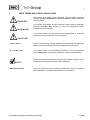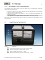
1
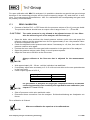
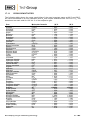
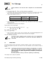
Operating Manual Portable Oxygene - Analyser Type PMA 10 and PMA 10S Gas sampling and gas conditioning technology 9-1.1-ME 2 Content 1 2 3 4 5 6 General information ................................................................................................................. 5 Declaration of conformity ........................................................................................................ 5 Safety instructions................................................................................................................... 6 Warranty ................................................................................................................................... 6 Used terms and signal indications ......................................................................................... 7 Introduction .............................................................................................................................. 8 6.1 Serial number............................................................................................................ 8 7 Application ............................................................................................................................... 8 8 Technical data .......................................................................................................................... 9 9 Description ............................................................................................................................. 10 9.1 Front panel.............................................................................................................. 11 9.2 Gas flow diagram of the analyser PMA 10(S) ........................................................... 12 9.3 Options ................................................................................................................... 12 9.3.1 Approval according to 13. and 17. BImSchV and TA-Luft (not for PMA 10S) ...... 12 9.3.2 Output signal .................................................................................................... 12 9.3.3 Rechargeable battery........................................................................................ 12 9.3.4 Sample gas pump ............................................................................................. 12 9.3.5 Alarm contact outlet (not for PMA 10S) ............................................................. 12 10 The measuring principle........................................................................................................ 13 11 Receipt of goods and storage ............................................................................................... 14 12 Installation .............................................................................................................................. 14 12.1 Connection of Sample gas inlet and sample gas outlet ............................................. 15 13 Standard gas conditioning system ....................................................................................... 15 14 Electrical connection ............................................................................................................. 16 14.1 Signal output ........................................................................................................... 16 14.2 Option alarm contact output ..................................................................................... 16 14.2.1 Adjustment of the alarm threshold .................................................................... 17 15 Connections on the rear side ................................................................................................ 17 16 Starting up .............................................................................................................................. 18 16.1 Execution with rechargeable battery ........................................................................ 18 17 Calibration .............................................................................................................................. 18 17.1 Zero calibration ....................................................................................................... 19 17.1.1 Cross sensitivities ............................................................................................. 20 17.1.2 Consideration of cross sensitivities ................................................................... 21 17.2 Span calibration ...................................................................................................... 22 18 Measuring ............................................................................................................................... 23 19 Closing down ......................................................................................................................... 24 20 Maintenance ........................................................................................................................... 24 20.1 Check and change of the internal filter element ........................................................ 24 21 Trouble shooting.................................................................................................................... 25 22 Spare parts list ....................................................................................................................... 26 23 Appendix ................................................................................................................................ 26 Gas sampling and gas conditioning technology 9-1.1-ME 3 List of Illustrations Figure Figure Figure Figure Figure Figure Figure Figure Figure 1 2 3 4 5 6 7 8 9 Dimensions ...................................................................................................... 10 Front panel....................................................................................................... 11 Gas flow diagram PMA 10(S) ............................................................................ 12 Scheme of the measuring cell and optical signal processing.............................. 13 Standard gas conditioning system .................................................................... 15 Plug connection signal output ........................................................................... 16 Rear side ......................................................................................................... 17 PMA 10(S) with open housing ........................................................................... 25 Component buildup .......................................................................................... 27 Gas sampling and gas conditioning technology 9-1.1-ME 4 Dear customer, we have made up this operating manual in such a way that all necessary information about the product can be found and understood quickly and easily. Should you still have any question, please do not hesitate to contact M&C directly or go through your appointed dealer. Respective contact addresses are to be found in the annexe to this ope rating manual. Please also contact our homepage www.mc-techgroup.com for further information about our products. There, you can read or download the data sheets and operating manuals of all M&C products as well as further information in German, English and French. This Operating Manual does not claim completeness and may be subject to technical modifications. © 07/1993 M&C TechGroup Germany GmbH. Reproduction of this document or its content is not allowed without permission from M&C. PMA® is a registered trade mark. 4th Edition: 12/2011 Gas sampling and gas conditioning technology 9-1.1-ME 5 HEAD OFFICE M&C TechGroup Germany GmbH Rehhecke 79 40885 Ratingen Germany Telephone: 02102 / 935 – 0 Fax: 02102 / 935 – 111 E - mail: [email protected] www.mc-techgroup.com 1 GENERAL INFORMATION The product described in this operating manual has been examined before delivery and left our works in perfect condition related to safety regulations. In order to keep this condition and to guarantee a safe operation, it is important to heed the notes and prescript ions made in this operating manual. Furthermore, attention must be paid to appropriate transportation, correct sto rage, as well as professional installation and maintenance work. All necessary information a skilled staff will need for appropriate use of this product are given in this operating manual. 2 DECLARATION OF CONFORMITY CE - Certification The product described in this operating manual complies with the following EC directives: EMV-Instruction The requirements of the EC directive 2004/108/EC “Electromagnetic compatibility“ are met. Low Voltage Directive The requirement of the EC directive 2006/95/EC “Low Voltage Directive“ are met. The compliance with this EC directive has been examined according to DIN EN 61010 as well as DIN 57721 for the voltage test of heating elements. Declaration of conformity The EU Declaration of conformity can be downloaded from the M&C homepage or directly requested from M&C. Gas sampling and gas conditioning technology 9-1.1-ME 6 3 SAFETY INSTRUCTIONS Please take care of the following basic safety procedures when mounting, starting up or operating this equipment: Read this operating manual before starting up and use of the equipment. The information and warnings given in this operating manual must be heeded. Any work on electrical equipment is only to be carried out by trained specialists as per the regulations currently in force. Attention must be paid to the requirements of VDE 0100 (IEC 364) when setting high -power electrical units with nominal voltages of up to 1000 V, together with the assoc iated standards and stipulations. Check the details on the type plate to ensure that the equipment is connected to the correct mains voltage. Protection against touching dangerously high electrical voltages: Before opening the equipment, it must be switched off and hold no voltages. This also applies to any external control circuits that are connected. The device is only to be used within the permitted range of temperatures and pressures. Check that the location is weather-protected. It should not be subject to either direct rain or moisture. The device must not be used in hazardous areas. Installation, maintenance, monitoring and any repairs may only be done by authorized personnel with respect to the relevant stipulations. 4 WARRANTY If the equipment fails, please contact M&C directly or else go via your appointed M&C dealer. We offer a one year warranty as of the day of delivery as per our normal terms and conditions of sale and assuming technically correct operation of the device. Consumables are hereby excluded. The terms of the warranty cover repair at the factory at no cost or the replacement at no cost of the equipment free ex user location. Reshipments must be sent in a sufficient and proper protective packaging. Gas sampling and gas conditioning technology 9-1.1-ME 7 5 USED TERMS AND SIGNAL INDICATIONS D AN G E R ! This means that death, severe physical injuries and/or important material damages will occur in case the respective safety measures are not fulfilled. WARNING ! This means that death, severe physical injuries and/or important material damages may occur in case the respective safety measures are not fulfilled. This means that minor physical injuries may occur in case the respective safety measures are not fulfilled. C AU T I O N ! CAUT ION! Without the warning triangle means that a material damage may occur in case the respective safety measures are not met. AT T ENT ION This means that an unintentional situation or an unintentional status may occur in case the respective note is not respected. NOT E! SKILLED STAFF These are important information about the product or parts of the operating manual which require user’s attention. These are persons with necessary qualification who are familiar with installation, use and maintenance of the product. Gas sampling and gas conditioning technology 9-1.1-ME 8 6 INTRODUCTION The portable M&C oxygen analyser PMA 10(S) is an non-thermostated instrument which has been designed for continuous and discontinuous measurement of oxygen concentrations in dry and particle-free sample gases. 6.1 SERIAL NUMBER The type plate with the serial number is on the back side of the analyser. Whenever you call M&C regarding questions or orders for the spares please give us the serial number of your PMA 10(S). 7 APPLICATION The PMA 10(S) is based on the magneto dynamic oxygen measuring cell of M&C. This measuring principle is one of the most accurate methods for oxygen determination within the range of 0 - 100 Vol.% O 2. The robust measuring cell is unique in design and construction. Due to the extremely fast response time of the M&C magneto-dynamic measuring cell with no stagnant volume as well as the negligible cross sensitivity from other sample gas components, the portable M&C oxygen analyser PMA 10(S) has a wide variety of applications. The analyser is a suitable and reliable instrument for monitoring oxygen concentrations in various gas analytical control applications including flue gas-, inert gas-, fermentation processes-, food packing machines-, ambient air- and laboratory process control measurements. It is characterized by safety in operation, robustness, accuracy and the need of low maintenance. Gas sampling and gas conditioning technology 9-1.1-ME 9 8 TECHNICAL DATA Oxygen analyser Series PMA Part No. Measuring ranges Indication Output signal Response time for 90% FSD Accuracy after calibration Reproducibility Influence of ambient temperature Influence of barometric pressure Influence of sample gas flow Sample gas inlet pressure Sample gas outlet pressure Flow rate of sample gas Temperature of sample gas Analyser temperature Ambient temperature Storage temperature Power supply Version PMA 10 and PMA 10S PMA 10 : 01A1000 = 230V 50Hz, 01A1000a = 115V 60Hz PMA 10S : 01A2000 = 230V 50Hz, 01A2000a = 115V 60Hz selectable for 0-3, 0-10, 0-30 and 0-100 vol.% O2, linear PMA 10S additional 9x% - 100% (e.g. 99% - 100%) analogue / digital meter: analogue meter selectable for each range with a scale of 0-30 and 0-100% digital meter, 3 1/2 digit 9 mm high LCD for 0-100 % O2 reading, selectivity 0,1 vol.% O2 0-1V DC, non-isolated, load > 100 KΩ, for each selected range; < 3 seconds at 60 Nl/hr air analogue = ± 1% of span / digital = ± 0,1 vol.% O 2 error of precision PMA 10S within additional measuring range : ±3 Vol.% O2 of measuring range analogue = < 1% of span / digital = ± 0,1 vol.% O2 error zero point ± 0,02 vol.% O 2 / °C; sensitivity ± 0,1 vol.% O 2 / °C The oxygen reading varies in direct proportion to changes of the barometric pressure. variation in gas flow between 0-60 Nl/hr air will cause a difference of < 0,1 vol.% O2 . 0,01 up to 1 bar g, (PMA 10 required admission pressure for competent flow rate, no pump inside) Outlet of analyser must discharge freely into atmosphere. max. 60 Nl/hr air, adjustable with needle valve on the flowmeter 7-70 Nl/hr -10 °C up to +40 °C, dry gas according to ambient temperature, non heated version -10 °C up to +55 °C -20 °C up to +60 °C, relative humidity 0-90% RH internal power unit for 230VAC standard or 115VAC available (a)* +/-10%, 4060Hz, 8VA mains supply: 3-pole chassis plug with 2m of cable; signal: 3-pole plug Platinum, Glass, Polypropylene, Stainless Steel 316, FPM, Epoxy resin PP-hose nipple for DN 11-4 mm tube IP 41 EN 60529 / EN 61010 portable plastic housing / gray height 150 mm, width 202 mm, depth 260 mm / approx. 3 kg Electrical connections Materials in contact with sample gas Sample gas connection Protection / electrical standard Housing / colour Dimension / weight Options 01A9000 Extra charge for signal output 4-20mA incorporated in the analyser PMA 10/10S (0-20mA on request), max. burden 300Ω 01A9100 Extra charge for gas sample pump incorporated in analyser type PMA 10. Capacity: 0,9 Nl/min without pressure. 01A9102 Extra charge for gas sample pump incorporated in analyser type PMA 10. Capacity: 1 Nl/min without pressure. 01A9050 Extra charge for PMA 10 with battery operation, battery charger incorporated in the analyser 01A9150 Min.* oder Max.* Alarmkontakt, von 0-100% O2 einstellbar Extra charge for alarm contact at analyser type PMA 10, adjustable from 0-100%O2. Potential-free changeover contact with plug at the rear of the housing. (not for PMA 10S) 01A9155 Extra charge for PMA 10 with Piezo acoustic alarm and automatic reset (30 sec.) (only in combination with alarm 01A9150). (not for PMA 10S) 01A9156 Extra charge for PMA 10 with Piezo acoustic alarm and manual reset (30 sec) (only in combination with alarm 01A9150). (not for PMA 10S) 01A9160 Extra charge for qualification test according to TA-Luft + EN 14181 resp. 13. and 17. BImSchV of analyser type PMA 10. Incl. signal output: 4-20mA (0-20mA on request) (not for PMA 10S) Gas sampling and gas conditioning technology 9-1.1-ME 10 9 DESCRIPTION The PMA 10 is a reliable and easy-to-operate instrument and immediately operable. The lightweight instrument is built into a portable housing. The four measuring ranges are displayed on the analogue meter with 30% and 100% scale and the 100% O 2 range also on the digital meter. One output signal 0-1V is available as standard. Sample gas connections as well as a connector for the output signal are located on the front panel of the analyser. The connectors for incoming power supply and optional O 2 alarm contact are located at the rear panel. The sample gas enters the analyser via an internal protective fine-filter. The required flow rate can be adjusted at the flowmeter with a needle valve, mounted on the front panel upstream the M&C measuring cell. Options: mA-output signal, O 2 alarm, rechargeable battery, internal pump and TÜV certificate. The PMA 10S oxygen purity analyser, being an extended version of the PMA 10, is provided with an electronic suppression system which enables oxygen purity measureents within the expanded 99-100 vol.% range. This measuring range is displayed on the analogue meter whilst the digital indicator remains for the 0-100% reading. The electronic zero suppression system may be selected by means of a push button switch which is located on the control panel of the instrument. The PMA 10S analyser can normally be used also for its standard PMA10 functions. Oxygen purity measurements could only be made discontinuously. The measuring accuracy of the analyser can be maintained when calibration of the instrument with a certified gas takes place before the measurement procedure in order to avoid influence of ambient temperature and pressure. A measurement of 1 vol.% can be easily realized whilst the maximum value remains at 100 vol.%. Other measurement within this range can be performed. The physical measuring principle is based on the magneto-dynamic oxygen measuring cell and is one of the most accurate methods for oxygen determination within the range of 0 - 100 Vol.% O 2. The measuring cell has a low volume of only 2 ml, is very robust, has an extremely low drift and a very fast response time. The 90%-time is approximately 3 sec. and is achieved by a gas flow rate of 60 Nl/hr through the measuring cell. The change of the flow in the range of 0 – 60 Nl/hr air causes a change of the O 2 indication of < 0,1 vol. % O 2. An internal power supply unit provides the analyser with the necessary supply voltage. At the rear side there is the low heat device socket. NOT E! Figure 1 The analyser is not thermostated and should be operated only in areas with constant ambient temperature. If this is not possible, the analyser has to be calibrated before every measurement, to guarantee the accuracy of measurement. Dimensions Gas sampling and gas conditioning technology 9-1.1-ME 11 9.1 FRONT PANEL Figure 2 1 2 3 4 5 6 7 8 9 10 11 Front panel Analog-/ digital-indication Flow meter Needle valve 7 – 70 Nl/hr Alarm potentiometer – option (PMA 10) or LED active measuring range (PMA 10S) Alarm-button – option (PMA 10) or switch for suppressed measuring range (PMA 10S) Span potentiometer Measuring range selector switch Zero potentiometer Sample gas - In DN 11-4 mm Sample gas - Out DN 11-4 mm Signal - Out 3-pole At the rear side there are: Low heat device socket with 2 fine fuses for power supply Push button for battery check - Option Switch for the sample gas pump - Option 3 pole bushing for alarm contact outlet - Option Gas sampling and gas conditioning technology 9-1.1-ME 12 9.2 1 2 GAS FLOW DIAGRAM OF THE ANALYSER PMA 10(S) Fine filter Flow meter with needle valve Figure 3 9.3 9.3.1 3 4 Measuring cell Sample gas pump - Option Gas flow diagram PMA 10(S) OPTIONS APPROVAL ACCORDING TO 13. AND 17. BIMSCHV AND TA-LUFT (NOT FOR PMA 10S) The approval happened by: Rheinisch-Westfälischer Technischer Überwachungs-Verein e.V. Essen. These devices have the label " TÜV eignungsgeprüft" at the front side. In connection with this approval a 4 -20 mA output is always necessary. 9.3.2 OUTPUT SIGNAL For output signal 0 – 1V an output signal 0 – 20 or 4 – 20 mA is available as option. The 3-pole connection bushing is provided on the front panel of the analyser. 9.3.3 RECHARGEABLE BATTERY The analyser PMA 10(S) can be finished with a rechargeable battery. Hereby an operation off the line is possible. The internal mains adapter than simultaneously is used as battery charger. 9.3.4 SAMPLE GAS PUMP A sample gas pump with a capacity of 1 l/min – without pressure can be integrated in the device. The pump is designed for short time rating only. For long-term operation an external sample gas pump has to be be used. 9.3.5 ALARM CONTACT OUTLET (NOT FOR PMA 10S) It is possible to adjust the alarm value via a potentiometer on the front panel to any value and it is switched as a min. or max. contact. The outlet is a potential-free change over contact that is lead through via a plug at the rear side. Additionally an acoustic alarm with automatic or manual reset (30 sec.) is integrable. Gas sampling and gas conditioning technology 9-1.1-ME 13 10 THE MEASURING PRINCIPLE Oxygen is a gas with a significant paramagnetic susceptibility. The molecules of oxygen are a ttracted much more strongly by a magnetic field than the molecules of other gases. The measuring principle shown in the following is benefitting from these characte ristics of the oxygen. The great advantage of the paramagnetic measuring principle is the highly reduced cross sensitivity of the measurement to other components in the sample gas. Figure 2 shows the diagram of the measuring cell as well as the optical system for the detection of the dumbbell’s movement. GAS INLET 4 2 1 3 GAS OUTLET Figure 4 Scheme of the measuring cell and optical signal processing The measuring cell consists of two nitrogen-filled spheres which are arranged in the form of a dumbbell. In the dumbbell’s central point of rotation, a small mirror is placed. The dumbbell is surrounded by a wire coil needed for the compensation procedure. The described system is fixed rotationally symmetrical inside a glass tube via a tightening strap out of platinum and is srewed up with two pole pieces . Two permanent magnets are producing an inhomogeneous magnetic field. When oxygen is flo wing in, the molecues of the oxygen are drawn into the magnetic field. In consequence, the lines of electric flux on the cuneiform pole pieces are compressed. The nitrogen-filled diamagnetic sheres are pushed out of the magnetic field. This causes a rotation of the dumbbell. The rotation is detected via an optical system consisting of mirror , projection LED and photoelectric cell . In case the dumbbell is pushed out of the magnetic fieild, the tension of the photoelectric cell is immediately changed. The measuring amplifiers and are producing a respective current which develops via the wire coil on the dumbbell an electro-magnetic load moment. The load moment is resetting the dumbbell into its zero position. Gas sampling and gas conditioning technology 9-1.1-ME 14 Every change of the oxygen concentration produces a lineary proportional change of the co mpensation current and can be read directly in % O 2 as oxygen value on the display . Due to its very small stagnant volume (2 cm 3) and the direct flow of the M&C measuring cell, an extremely fast response time (T 90-time) of 1 second for a high gas flow can be realized. 11 RECEIPT OF GOODS AND STORAGE The analyser PMA 10(S) is a completely pre-installed unit. Please take the analyser and possible special accessories carefully out of the packaging m aterial immediately after arrival, and compare the goods with the items listed on the packing list; Check the goods for any damage caused during delivery and, if necessary, notify your tran sport insurance company without delay of any damage discovered. NO T E ! 12 The oxygen analyser PMA 10(S) must be stored in a wheather protected and frost-proof area ! INSTALLATION The PMA 10(S) is intended for mobile operation at always changing locations. In combination with a good gas conditioning (e.g. PSS-5, Part No. 01G1100) a long lasting operability and a minimum of maintenance is guaranteed. C AU T I O N ! C AU T I O N ! D AN G E R ! The sample gas has to be dust free and dry to prevent a contamination and condensation in the analyser. Basically always connect a fine filter (e.g. type FP-2T, Part No. 01F1200) upstream. In case of outdoor operation protect the analyser against sun, wind and rain. At the installation location constant climatic ambient conditions (pressure, temperature) are necessary to prevent a distortion of the measurement and a condensation in the measuring cell in case the ambient temperature is falling below the dew point temperature of the sample gas. A vibration-free location is ideal for mounting; if this is not possible, appropriate measures have to be taken. The analyser must not be installed in direct proximity of heat sources. The position of operation is not necessarily horizontal. The analyser is allowed to be operated only in non-hazardous areas and with non-ignitiable gases and gas mixtures. Gas sampling and gas conditioning technology 9-1.1-ME 15 12.1 CONNECTION OF SAMPLE GAS INLET AND SAMPLE GAS OUTLET The sample gas inlet and outlet are placed on the front panel of the analyser and have a hose nipple connection DN 11 – 4 mm. Connect the sample gas inlet with a corresponding gas conditioning with e.g. a flexible PVC hose DN4/6. Avoid back pressure in the sample gas outlet because an increase of pressure will distort the oxygen indication. Do not bend the connection hoses. AT T ENT ION 13 STANDARD GAS CONDITIONING SYSTEM PMA PMA10(S) 10 +5°C Figure 5 1 2 3 4 5 6 : : : : : : Standard gas conditioning system Heated gas sample probe (e.g. portable probe PSP4000-H) Heated gas sample line (e.g. PSP4M4/6) Sample gas cooler Peristaltic pump or condensate collecting vessel Diaphragm pump Fine filter (3 - 6 e.g. portable gas sampling system PSS-5) Gas sampling and gas conditioning technology 9-1.1-ME 16 14 ELECTRICAL CONNECTION WARNING ! False supply voltage can damage the equipment. When connec ting the equipment, please ensure that the supply voltage is identical with the information provided on the model type plate! At the rear side there is the low heat device socket. A 2m connection cable with low heat device connector and earthing type plug is included in the scope of delivery. 14.1 SIGNAL OUTPUT The PMA 10(S) has a signal output of 0 – 1V as standard, that is available in the chosen measuring range at the 3-pole bushing in the front of the analyser ( Pin 1/- und 3/+). With option mA-output, additionally a signal of 0 - 20 mA or 4 - 20 mA is available at the 3-pole bushing in the front of the analyser ( Pin 1/- und 2/+). The output signals are not galvanically isolated. For the connection of the signal output an adequate plug is provided. Figure 6 14.2 Plug connection signal output OPTION ALARM CONTACT OUTPUT The alarm contact output is designed as MIN- as well as MAX-contact. Ex works the analyser is delivered with a MAX-contact. If a MIN-contact is favoured, the 4 screws of the front panel have to be removed and the switch S2 on the alarm-board has to be switched. For output a relais contact (change over contact) and optionally a buzzer is available. The intermitting buzzer switches off after 30 seconds automatically or has a manual reset as option. The relais contact is lead to a female plug at the rear side. A corresponding plug with the following assignment is included in the s cope of delivery (see also Fig. 7) : Contact 1 2 3 Assignment mc nc no Explanation Tie point Normally closed Normally open Gas sampling and gas conditioning technology Contact rating max. 2A max. 24V DC /100V AC 9-1.1-ME 17 14.2.1 ADJUSTMENT OF THE ALARM THRESHOLD For adjustment of the alarm treshold on the front panel there is a potentiometer marked with “alarm” and aside a push-button: Actuate the push-button and keep it pressed. Now the digital indication of the indication instrument shows the alarm threshold. Adjust the alarm threshold in the range of 0 – 100 % O2 at the alarm potentiometer with suitable screw driver. After adjustment of the desired alarm threshold release push button. The alarm threshold now is adjusted and the digital indication again shows the current measurement. The position of the measuring range selector switch is not relevant for the adjustment of the alarm threshold. 15 CONNECTIONS ON THE REAR SIDE Figure 7 Rear side Low heat device socket with 2 fine fuses for power supply Space for push-button for battery check - Option Space for pump switch ON-OFF - Option Space for 3-pole bushing for alarm contact output - Option Gas sampling and gas conditioning technology 9-1.1-ME 18 16 STARTING UP WARNING ! Check electrical connections and gas connections. Switch on mains voltage. Turn measuring range selection switch from „0“ to the desired measuring range. The analyser is ready for operation immediately. CAUT ION! 16.1 False supply voltage can damage the equipment. When connec ting the equipment, please ensure that the supply voltage is identical with the information provided on the model type plate! If during transport the analyser was exposed to extreme changes of temperature, an adequate time for temperature adaption has to be observed, to prevent condensation in the device. EXECUTION WITH RECHARGEABLE BATTERY Check charge condition of the battery. For that purpose actuate the push-button „battery check“ at the rear side of the device. The digital indication has to show a value of min. 83. Ist der Wert geringer, muss der Akku aufgeladen werden. For this connect the low heat device connector of the provided connection cable at the rear side with the low heat device socket and the earthing type plug with the mains power. In position “0” of the measuring range selector switch the battery is charged in approximately 14 hours. NO T E ! Never fully discharge the battery (battery check indication < 83), hereby the life time is reduced. The analyser with battery also can be operated alwaysat the mains. 17 CALIBRATION The accuracy of an analyser mainly is dependent on its calibration. NO T E ! Before calibration it has to be assured that the calibration conditions correspond to the conditions during measurement. The flow rate, the ambient temperature and the barometric pressure conditions have to be constant. Under this terms a calibration of the analyser is necessary aproximately one time a week to maintain the accuracy. If flow rate, ambient temperature or barometric pressure conditions are changing significantly, a new cal ibration is necessary. During calibration the device must not be exposed to vibrations. For zero calibration of the analyser an oxygen-free gas, mostly nitrogen (N 2 5.0) is used. Gas sampling and gas conditioning technology 9-1.1-ME 19 For span calibration with M&C O2-analysers it is possible to abandon on special test gas mixtures because of the measuring principle and the linear measuring ranges. Dry and clean air is sufficient. For measurement concentrations > 40% O 2 a calibration with corresponding test gas could be possibly recommandable. 17.1 ZERO CALIBRATION Connect a flexible PVC- or FEP-hose with the pressure reducer of the N2-zero-gas bottle. The pressure reducer should have an output control range of max. 0 – 1,5 bar abs.. CAUT ION! Open the bottle valve and than the closed pressure reducer outlet valve and purge the pressure reducer and the complete hose line for approximately 5 sec. the pressure reducer and the complete hose line. Check the adjusted control pressure and reduce if necessary to ≤ 0,1bar, then shut off the pressure reducer valve again. Connect the hose end of the zero-gas bottle connection to the gas inlet of the analyser. Open the pressure reducer valve slowly, to avoid pressure peaks. Adjust the flow rate to 50 Nl/hr at the flow meter. NO T E ! The outlet pressure is only allowed to be adjusted at max. 0,1 bar. Otherwise the measuring cell of the analyser will be destroyed. Always calibrate at the flow rate that is adjusted for the measurement too. Wait approximately 20 – 30 sec. until the indication has stabilised. If necessary adjust zero accurately to 0 % O 2 with a screw driver at the zero potentiometer in the front panel Check output signals at 0,0% O 2 : Output signal 0-1 V 0-20 mA 4-20 mA NO T E ! Measurement 0V 0 mA 4 mA If a gas mixture is analysed, the single gas components have to be checked concerning potential cross sensitivity and regarded for zero calibration. (see chapter 17.1.1 and 17.1.2). Shut off pressure outlet valve and bottle valve. Disconnect hose connection from the analyser. Schlauchverbindung am Analysator entfernen. Zero calibration is finished. After zero calibration the span has to be calibrated too. NO T E ! Gas sampling and gas conditioning technology 9-1.1-ME 20 17.1.1 CROSS SENSITIVITIES The following table shows the cross sensitivities of the most important gases at 20 °C and 50°C. All values are based on a zero calibration with N 2 and a span calibration with 100 Vol.% O 2. The deviations are each valid for 100 Vol.% of the respective gas. Gas Acetaldehyde Acetone Acetylene Ammonia Argon Benzene Bromine Butadiene n-Butane Iso Butylen Chlorine Diacetylene Nitrous monoxide Ethane Ethylbenzene Ethylene Ethylene glycol Ethylene oxide Furan Helium n-Hexane Hydrogen chloride Hydrogen fluoride Hydrogen sulfide Carbon dioxide Carbon monoxide Krypton Methane Methanol Methylen chloride Methyl propene Monosilan Neon n-Octane Phenol Propane Propylene Propylene chloride Propylene oxide Oxygen Sulfur dioxide Sulfur fluoride Monosilane Nitrogen Nitrogen dioxide Nitrogen monoxide Styrene Toluene Vinyl chloride Vinyl fluoride Water (Steam) Hydrogen Xenon Molecular formula C2H4O C3H6O C2H2 NH3 Ar C6H6 Br2 C4H6 C4H10 C4H7 Cl2 (CHCl)2 N2O C2H4 C8H10 C2H4 (CH2OH)2 C2H4O2 C4H4O He C6H14 HCL HF H2S CO2 CO Kr CH4 CH4O CH2Cl2 C4H8 SiH4 Ne C8H18 C6H6O C3H8 C3H6 C3H7Cl C3H6O O2 SO2 SF6 SiH4 N2 NO2 NO C8H8 C7H8 C2H3Cl CH3F H2O H2 Xe Gas sampling and gas conditioning technology 20°C - 0,31 - 0,63 - 0,26 - 0,17 - 0,23 - 1,24 - 1,78 - 0,85 - 1,10 - 0,94 - 0,83 - 1,09 - 0,20 - 0,43 - 1,89 - 0,20 - 0,78 - 0,54 - 0,90 + 0,29 - 1,78 - 0,31 + 0,12 - 0,41 - 0,27 - 0,06 - 0,49 - 0,16 - 0,27 - 1,00 - 0,94 - 0,24 + 0,16 - 2,45 - 1,40 - 0,77 - 0,57 - 1,42 - 0,90 +100,00 - 0,18 - 0,98 - 0,24 0,00 + 5,00 + 42,70 - 1,63 - 1,57 - 0,68 - 0,49 - 0,03 + 0,23 - 0,95 50°C - 0,34 - 0,69 - 0,28 - 0,19 - 0,25 - 1,34 - 1,97 - 0,93 - 1,22 - 1,06 - 0,91 - 1,20 - 0,22 - 0,47 - 2,08 - 0,22 - 0,88 - 0,60 - 0,99 + 0,32 - 1,97 - 0,34 + 0,14 - 0,43 - 0,29 - 0,07 - 0,54 - 0,17 - 0,31 - 1,10 - 1,06 - 0,27 + 0,17 - 2,70 - 1,54 - 0,85 - 0,62 - 1,44 - 1,00 +100,00 - 0,20 - 1,05 - 0,27 0,00 + 16,00 + 43,00 - 1,80 - 1,73 - 0,74 - 0,54 - 0,03 + 0,26 - 1,02 9-1.1-ME 21 17.1.2 CONSIDERATION OF CROSS SENSITIVITIES The selectivity of the above mentioned measuring principle is based on the high suscep tibility of oxygen to other gases (see table). The following examples shall show how cross sensitivities can be considered for the zero calibr ation. Example 1: Determination of the rest content of oxygen in a 100% carbon dioxide (CO2) protective atmosphere at 20°C In the table of cross sensitivities you can read the value for CO 2 at 20°C of –0,27. This means that for calibration with nitrogen the zero point must be set to +0,27% in order to compensate the deviation of the display. In this example, the atmosphere contains exclusively CO 2 and O 2. For this reason, the influence of cross sensitivity can be eliminated without problem by using carbon dioxide (CO 2) instead of nitrogen for the zero calibration. Example 2: Determination of the oxygen content of a gas mixture at 20°C 1 Vol.% C2H6 (Ethane); 5 Vol.% O 2; 40 Vol.% CO 2; 54 Vol.% N2. Zero point calibration with nitrogen (N 2). The cross sensitivity values of above table are based on 100 Vol.% of the respective gases. Therefore, a conversion must be maid to the effective volume concentration. In principle, the fo llowing is valid: Effective cross sensitivity = Table value * Volume concentration [Vol.%] 100 For the components of the gas mixture, the following values are found: C2H6 : -0,0043 Vol.%; CO2 : -0,1080 Vol.%; N2 : 0,0000 Vol.%. = -0,1123 Vol.% To determine the sum of cross sensitivity as exactly as possible, a correction factor has to be determined, because the sum of cross sensitivities relates not on 100% but on 100% minus the oxygen concentration (here 95%). Gas sampling and gas conditioning technology 9-1.1-ME 22 The correction factor is calculated as follows: Correction factor = 100 (100 – O2-concentration) It is incidental: 100 = 1,0526 (100 – 5) For the gas mixture the rectified sum cross sensitivity then is calculated in good approximation : 1,0526 x -0,1123 Vol.% = -0,1182 Vol.% The rectified sum cross sensitivity with change of sign now can be used for the correction of the zero calibration. In this case zero had to be adjusted at +0,1182 Vol.%. In case the cross sensitivities should be ignored in the above mentio ned example, this would result in a relative error of approximately 2%. After zero calibration the span has to be calibrated too. NO T E ! 17.2 SPAN CALIBRATION Before span calibration a finished zero calibration is necessary. Connect a flexible PVC- or FEP-hose with the pressure reducer of the N 2-zero-gas bottle. The pressure reducer should have an output control range of max. 0 – 1,5 bar abs.. CAUT ION! The outlet pressure is only allowed to be adjusted at max. 0,1 bar. Otherwise the measuring cell of the analyser will be destroyed. Open the bottle valve and than the closed pressure reducer outlet valve and purge the pressure reducer and the complete hose line for approximately 5 sec. the pressure reducer and the complete hose line. Check the adjusted control pressure and reduce if necessary to ≤ 0,1bar, then shut off the pressure reducer valve again. Connect the hose end of the instrument air or check gas bottle connection to the gas inlet of the analyser. Open the pressure reducer valve slowly, to avoid pressure peaks. Adjust the flow rate to 50 Nl/hr at the flow meter. Gas sampling and gas conditioning technology 9-1.1-ME 23 NO T E ! Always calibrate at the flow rate that is adjusted for the measurement too. Wait approximately 20 – 30 sec. until the indication has stabilised. If necessary adjust span accurately according to the check gas concentration with a screw driver at the span potentiometer in the front panel. In case of air e.g. to 20,9 % O2. Check output signals at 20,9% O2 : Output signal 0-1 V 0-20 mA 4-20 mA Measurement range 100 % O 2 0,209 V 4,18 mA 7,34 mA Measurement range 30 % O 2 0,697 V 13,93 mA 15,15 mA Shut off pressure reducer valve and bottle- resp. Instrument air valve resp. integrated sample gas pump. Disconnect hose connection at the analyser. Determination of the output signal: (Se – S np) V resp. mA x gas concentration Vol % O 2 upper range value Vol % O2 + S np Se = Final value, signal output Snp = Zero, signal output Shut off pressure reducer output valve and bottle valve. Druckreglerausgangsventil und Flaschenventil schließen. Disconnect hose connection at the analyser. The span calibration is finished. NO T E ! 18 If during the span calibration great variations have to be compensated (>2% O 2) at the potentiometers, a second zero and span calibration is reasonable. MEASURING For the first starting up at a new location, all steps in chapter 16 and 17 have to be performed. By the requirements of precision the interval of the new calibration can be carried out daily or weekly. CAUT ION! The sample gas must be free from all liquid or solid particles, i.e. the dew point of the gas must be below the equipment temperature so that no condensate will occur inside the equipment. If necessary, lower the dew point by means of a cooler or dryer. For dust filtration use a filter of 2 micron porosity ! We will be pleased to inform you about an optimal gas conditioning The analyser now is ready for operation. Gas sampling and gas conditioning technology 9-1.1-ME 24 19 CLOSING DOWN In case of a short time closing down of the the analyser no further precautions are required. In case of a closing down of the analyser for a longer period, it is recommended to flush the an alyser with dry and clean inert gas (eg. surrounding air) in order to prevent a d amage of the measuring cell by aggressive and corrosive liquid gases. For analyser with option rechargeable battery it is recommended for short or long term closing down to remain the analyser at the mains. Hereby a deep discharge of the rechargeable battery will be avoided and the device always is 100% ready for operation . 20 MAINTENANCE The analyser, woking with a physical measuring principle, requires no intensive and complex maintenance. But the preceding components necessary for the sample gas conditioning are to be maintained with special attention according to the respective operating manuals. The calibration of zero and span is to be effected with the corresponding test gases according to stability of the operating conditions and to the demands on the accuracy. Recommended interval of calibration for standard applications: 1 x per week. 20.1 CHECK AND CHANGE OF THE INTERNAL FILTER ELEMENT The internal fine filter should be checked regularly for contamination and changed if necessary. For a change the device has to be opened as follows: Take analyser off the mains. Loosen front quick-opening screw 1 of the handle. Loosen corrugated-head screw of the right hinge pin, extract the pin and open the device. Pull hose 7 off the filter inlet and unscrew filter body (4, 5, 6). Unscrew filter element clamp 4 and change filter element 5. Reassamble again in reverse order. Gas sampling and gas conditioning technology 9-1.1-ME 25 1 2 3 4 Quick-opening screw O 2-transmitter-unit Filter body Filter element clamp Figure 8 21 5 6 7 Filter element Filter head with filter inlet Connection hose gas IN to filter PMA 10(S) with open housing TROUBLE SHOOTING Error Possible reason Check/Repair No indication No supply voltage Check supply voltage according to type plate. Check wether mains cable is plugged in accurate. Check fine fuse in the low heat device socket. No sample gas flow Sample line or filter is blocked Check sample system. Contamination of the in- Loosen hose at the pump head and check ternal diaphragm pump wether gas flow is present. Possibly open pump head and clean valves, diaphragm and pump head with a soap solution. Gas sampling and gas conditioning technology 9-1.1-ME 26 22 SPARE PARTS LIST Wear, tear and replacement part requirements depend on specific operating conditions. The recommended quantities are based on experience and they are not binding. Oxygen analyser PMA 10(S) (C) Consumable parts (R) Recommended spare parts (S) Spare parts Part No. Indication 90 A 0100 Filter element 0,1µm glass fibre PMA 10(S) 90 A 0068 O-Ring internal filter PMA 10(S) 90 A 0020 Zero potentiometer 5k 90 A0025 Span potentiometer 1k 90 A 0010 Measuring cell PMC 1 90 A 0015 Flowmeter glass 7-70 Nl/h 90 A 0085 Signal output plug for PMA 10(S) 90 A 0070 Nipple PP for sample gas output PMA 10(S) 90 A 0075 Nipple PP for sample gas input PMA10(S). 90 A 0045 Spare pump 0,9l/min PMA 10(S) 23 Recommended quantity being in operation [years] C/R/S 1 2 3 C R S S S R S R R S 4 2 - 8 4 1 12 6 1 1 1 1 1 1 1 1 APPENDIX Component buildup Further product documentation can be seen and downloaded from our home page: www.mc-techgroup.com Gas sampling and gas conditioning technology 9-1.1-ME 27 Figure 9 Component buildup Gas sampling and gas conditioning technology 9-1.1-ME