1
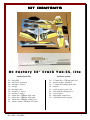
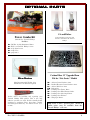
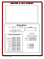
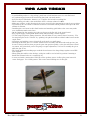
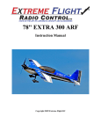
32” Crack Yak-55
By
RC Factory
Specifications
Wing span – 32” / Length – 31”
AUW 160-175g (with Landing Gear)
50 - 70w outrunner motor (19g – 24g)
6 - 12 amp ESC / 2s 360 – 450mAh battery
4 ch radio / 2x 4g servos / 1x 9g servo
8x4.3 prop
USA Distributor
Twisted Hobbys
www.twistedhobbys.com
Rev: 2012.11.04.v004a
1
TABLE OF CONTENTS
Page
WARNING INFORMATION...................................................................................................................................................3
SHIPPING DAMAGE...............................................................................................................................................................3
OUR MISSION ..........................................................................................................................................................................3
SAFETY NOTES .......................................................................................................................................................................4
IMPORTANT: PRIOR TO ANY ASSEMBLY ..............................................................................................................4
KIT CONTENTS .......................................................................................................................................................................5
OPTIONAL PARTS ..................................................................................................................................................................6
TOOLS & ADHESIVES NEEDED..........................................................................................................................................7
THE BUILD ...............................................................................................................................................................................8
CENTER OF GRAVITY ........................................................................................................................................................48
CONTROL THROWS ............................................................................................................................................................48
3D Flight ..........................................................................................................................................................................48
Sport .................................................................................................................................................................................48
PRE-FLIGHT & TESTING ...................................................................................................................................................49
PREFLIGHT CHECKS ...............................................................................................................................................................49
Motor................................................................................................................................................................................49
Flight Controls .................................................................................................................................................................49
Batteries ...........................................................................................................................................................................49
Radio ................................................................................................................................................................................49
Range Check.....................................................................................................................................................................49
FLIGHT TESTING ....................................................................................................................................................................49
STORAGE ...............................................................................................................................................................................49
NOTES & S/U SHEET ............................................................................................................................................................50
TIPS AND TRICKS ................................................................................................................................................................51
Rev: 2012.11.04.v004a
2
TWISTED HOBBYS
Website: www.twistedhobbys.com – email: [email protected]
Thank you for your purchasing a Twisted Hobbys’ model. Please read through the entire manual before
beginning to build this model. If you have any questions please contact us at the above indicated email address.
WARNING INFORMATION
This R/C Aircraft is not a toy! Read and understand the entire manual before assembly. If misused, it can
cause serious bodily harm and property damage. Fly only in open areas, and AMA (Academy of Model
Aeronautics) approved flying sites. Do not over look the warnings and instructions enclosed or those provided
by other manufactures’ products. If you are not an experienced pilot and airplane modeler you must use the
help of an experienced pilot or an authorized flight instructor for the building and flying of this model aircraft.
These instructions are suggestions only on how to assemble this model. There are other ways and methods to
do so. Twisted Hobbys has no control over the final assembly, the materials and accessories used when
assembling this kit, or the manner in which the assembled model, installed radio gear and electronic parts are
used and maintained. Thus, no liability is assumed or accepted for any damage resulting from the use of the
assembled model aircraft or from this instruction manual including but not limited to direct, indirect,
incidental, special, and consequential damages. By the act of using this user-assembled product, the user
accepts all resulting liability. In no event shall Twisted Hobbys’ liability exceed the original purchase price of
the kit.
SHIPPING DAMAGE
Twisted Hobbys checks each plane before shipping to ensure that each kit is in fine condition. We have no
bearing on the condition of any component parts damaged by use, modification, or assembly of the model.
Inspect the components of this kit upon receipt. If you find any parts damaged or missing, contact Twisted
Hobbys immediately. We will not accept the return or replacement of parts on which assembly work has already
begun. Twisted Hobbys reserves the right to change this warranty at anytime without notice.
OUR MISSION
To provide the best products and service to our customers at the lowest prices possible.
We take great pride in our company, our commitment to customer service and in the
products we sell. Our online store is designed to provide you with a safe and secure
environment to browse our product catalog.
Thank you for shopping with Twisted Hobbys!
Rev: 2012.11.04.v004a
3
SAFETY NOTES
Before assembling and flying this model, read carefully any
instructions and warnings of other manufacturers for all the
products you installed or used on your model, especially radio
equipment and power source.
Check thoroughly before ever flight that the airplanes’
components are in good shape and functioning properly. If you
find a fault do not fly the model until you have corrected the
problem.
Radio interference caused by unknown sources can occur at any
time without notice. In such a case, your model will be
uncontrollable and completely unpredictable. Make sure to
perform a range check before every flight. If you detect a control
problem or interference during a flight, immediately land the
model to prevent a potential accident.
Youngsters should only be allowed to assemble and fly these
models under the instruction and supervision of an experienced
adult.
Do not operate this model in a confined area.
Do not stand in line with, or in front of a spinning propeller and
never touch it with any object.
IMPORTANT: PRIOR TO ANY ASSEMBLY
Please Note: after removing kit from shipping box, lay
each piece flat on a hard surface, this will allow the
airframe to straighten out if lightly bent from
shipping. Do not worry since EPP is very pliable and
can be bent back if out of shape.
Rev: 2012.11.04.v004a
4
kit contents
RC Factory 32” Crack Yak-55, lite
standard parts list:
2x
4x
1x
1x
2x
1x
1x
1x
1x
2x
2x
–
–
–
–
–
–
–
–
–
–
–
wing half
side force generator
fuselage (3 parts)
canopy
fuselage truss
elevator (1 parts)
rudder (1 parts)
3mm dia x 700mm wing spar
3mm dia x 300mm wing spar
1mm dia x 500mm control rod
1mm x 3mm x 200mm LG strut
Rev: 2012.11.04.v004a
hardware packet:
2x
1x
2x
2x
1x
4x
4x
4x
2x
–
–
–
–
–
–
–
–
–
1.5mm dia x 170mm push rod
motor mount, fiberglass
1.5mm dia landing gear axle
wheels
wood horn/accessory kit
heat shrink tubing pieces
z-bend wires
adjustable connectors
streamlined wheel pants
5
OPTIONAL PARTS
CA and Kicker
Power Combo Kit
(Matched by Twisted Hobbys)
includes:
1x –
1x –
2x –
1x –
1x –
Various thickness CA glues and
Activator available from Twisted
Hobbys’
50-70w 19-24g Outrunner Motor
ESC 12A Twisted Hobbys’ Series
4.5g digital servos
9.0g Servo
prop 8x4.3
Micro Receiver
Max Recommended Weight: 2.9g
Minimum of 4 channels required
Perfect choice for building and repairing your
Twisted Hobbys EPP planes! This is the only
adhesive you will ever need. Welder virtually bonds
anything to anything! Clear, heavy-duty, flexible
and water-proof when dry. Use indoors or out. (1) 1
oz tube
Rev: 2012.11.04.v004a
Carbon Fiber 32” Upgrade Horn
Kit for “Lite Series” Models
2x - Aileron Control Surface Arms
2x - Rudder/Elevator Control Surface Arms
1x - Aileron Diff Servo Arm
12x - Rod guides
1x - Landing Gear Frame Brace
2x - Landing Gear Wheel/Pants Guides
2x - Landing Gear Axle Angle Brace
4x - Landing Gear Washers
4x - Wing Spar Braces
Note: many of these “optional parts” shown or
similar items, may be available from the
Twisted Hobbys’ web store.
6
Tools & Adhesives Needed
• Tape Measure and Ruler
• Lighter
• Small drill bits
• Welders Glue
• Hobby Knife w/new Blade
Blade
• Needle Nose Pliers
• Wire Cutters
• Low Temp Hot Glue Gun
• Course Sand Paper
• Scissors
• Small Phillips Screw Driver
• CA and Activator
• Approx 18” string/thread
Rev: 2012.11.04.v004a
7
THE BUILD
CONSTRUCTION METHODS:
Building surface should be at least 2ft x 4ft and flat. Weights or some small heavy objects will be
handy for holding things in place during the time glue is setting.
Two types of glue are used for the build, Welders glue is use for most areas and CA for the horns
and guides. When using the Welders glue, apply a thin film to each surface,
surface, allow to sit for
approx five minutes
minutes and then assemble.
assemble. Note that this method will create a nearly instant bond,
so locate carefully when bringing the two pieces together. If alignment is necessary while gluing
the two pieces together, do not allow the glue to tack up, simple apply and join immediately, you
will have several minutes to locate the two parts before the glue sets up. In most cases the parts
being glued can be handled with care in 30 minutes, full cure is approx 24 hours.
Carbon parts should be sanded and wiped clean prior to gluing. Take necessary precautions to
avoid breathing the carbon dust.
Remove wing spar ribs that have the
oval holes from the wood kit. These are
for the inner spar slot where the spar is
two rods thick.
The center section, to the right in this
photo, is where the oval ribs and
double spar go.
Rev: 2012.11.04.v004a
8
Remove the little tabs of foam that are
in the SFG slots with a sharp knife
Glue the wings to the fuselage with
Welders. Notice how the tabs on each
wing prevent you from putting the
wings on upside down.
NOTE: USE GLUE SPARINGLY
AND WIPE OFF OR REMOVE ANY
EXCESS. TOO MUCH GLUE WILL
INCREASE THE A.U.W. AND
AFFECT THE MODEL’S FLYING
CHARACTERISTICS.
This is how the spar assembly goes
together. Short rod in the center first
followed by the longer rod over the top
of it.
Rev: 2012.11.04.v004a
9
Welders will work it’s way through the
top of the wing.
Use some clear
packing tape on the bench to keep it
from sticking. Wax paper or Parchment
paper could also be used.
Install the rods thru the wood ribs as
shown. Note that the shorter one is on
the bottom.
Wing tip rib shown. The hump on both
should be facing upward.
Rev: 2012.11.04.v004a
10
Lay down a bead of Welders into the
rib and spar areas. Lower the assembly
into the provided slots allowing any
extra glue to squish out.
The short spar should be buried in the
middle section and the long spar
should be flush with the bottom of the
wing. The humps in the ribs will stick
out on both inner and out ribs as
shown.
Fill any voids with glue and wipe up as
much
excess glue as possible.
Remember we want to keep things a
light as possible.
Rev: 2012.11.04.v004a
11
Weigh it down flat on a flat surface and
let it dry completely.
Pay special
attention to ensure that the wing is flat
and the spar is straight and true.
Get ready to install the elevator. Put
Welders on the end of the Fuse and let
it tack up.
Put Welders on the elevator, spread
thin, and let it tack up.
Rev: 2012.11.04.v004a
12
After tacking for a few minutes
assemble the elevator to the fuselage
piece. Notice there is a tab on the stab
and fuse that will keep you from
putting them on backwards.
Assembled elevator to fuselage.
Now install the lower part of the
fuselage. Put Welders on the tabs and
flat spots of the lower fuselage
Rev: 2012.11.04.v004a
13
Put Welders in the tab slots and flat
spots between the tab slots on the
horizontal fuse piece. Be cautious not
to put Welders in the servo hole areas.
Put the lower fuse onto the horizontal
fuse piece while the glue is wet. Make
sure it is 90 degrees to the horizontal
piece and clean up all the excess glue.
While the lower fuse is drying we will
install the aileron control horns. There
are two different shape control horns in
the kit. The ones angled the same as
the hinge line of the ailerons are the
correct ones.
Aileron Control Horn
Rev: 2012.11.04.v004a
14
Put Welders on the control horn.
Install the control horns while the glue
is wet and let dry. You may have to cut
out the EPP fuzz in the slot in the
wing to get the horn to sit flush. Trial
fit before gluing.
Also while the lower fuse and control
horns are drying, fold over the ailerons
and weight them down for a few
minutes to loosen up the hinges.
Rev: 2012.11.04.v004a
15
Install the upper part of the fuse.
Put Welders on the tab slots and flat
part of the fuse.
Put Welders on the flat parts and tabs
of the upper fuse piece, insert wet and
let dry. Take care to make sure the
upper fuse is in line with the lower fuse
and 90 degrees to the horizontal fuse
piece. Also make sure the front of all
the fuselage pieces are flush. This will
be important when mouting the motor.
Rev: 2012.11.04.v004a
16
Clean up any excess glue.
While the upper fuse is drying put
Welders on the canopy area and let it
tack up.
Put Welders on the canopy itself and
let it tack up.
Rev: 2012.11.04.v004a
17
After the glue has tacked up, attach the
canopy to the fuse. Make sure it is
going in the right direction!
Put Welders on the Fuse find side and
let it tack up.
Put Welders on the fuse fin side and let
tack up. Put Welders on th fin and let
it tack up. No need for glue in the
elevator joiner area where the half
circle is cut out.
Rev: 2012.11.04.v004a
18
While the glue tacks up install the
control horn in the rudder the same
way we did with the ailerons.
Rudder Horn
After the Welders has tacked up glue
the rudder to the fuse. Start at the top
so you can manage the fin to rudder
gap and work your way down.
While everything is drying, take the
time to keep tweaking it so that
everything dries perfectly straight.
Rev: 2012.11.04.v004a
19
Now you can install the elevator
control horn.
Elevator Horn
Now install the side trusses.
Cut one of the tips off the trusses so
that you can run the servo wires from
the tail servos out of the and tuck the
wires back into that space after it is all
finished to clean up the radio install.
Rev: 2012.11.04.v004a
20
Again, as the glue dries on the trusses
keep tweaking and checking to make
sure everything is totally straight.
These are all the parts to build the LG
assembly.
1X
2X
2X
2X
- Wood Landing Gear Parts
- Carbon Rounds for Axles
- Carbon Rectangles for Struts
– EPP Wheel Pants
Note – your kit may have 4 round
parts and no oval parts.
First thing you will want to do is drill
out the wheels with a 1/16” dia bit, so
that the carbon axles fit without
binding.
Rev: 2012.11.04.v004a
21
Second, you will glue the little ply
angle piece (Axle Support) to the end of
one of the gear legs with thin CA.
Axle Support
The angle and flat spot created by the
ply piece and the carbon gear leg makes
a nice joint to glue in the carbon axle
with thin CA.
You will put the little circular ply piece
over the carbon axle and CA it to the
ply angled piece to create a hub for the
wheel to run against.
If your kit has 4 of these parts, use two
per side; one to hold the inside of the
wheel and one to hold the outside.
Axle Washer
Rev: 2012.11.04.v004a
22
Make sure all the pieces are thin CA’d
securely.
Then wrap the whole joint with thread.
After it is wrapped with the thread, hit
it with thin CA and kicker to finish of
the gear leg.
Rev: 2012.11.04.v004a
23
This piece is very strong and light!
Next, you will put on the ply wheel
pant mount/wheel keeper. It just slides
over the axle and glues in place with
medium or if you are careful thin CA.
If your kit had 4 of the round washers,
make sure to put the second one on
before gluing on the Pant Support.
Wheel Pant Support
After your gear legs are made the
rectangle ply piece goes into the
fuselage here.
Note – on some kits the position of the
landing gear may be located closer to
the nose.
Landing Gear Bulkhead
Rev: 2012.11.04.v004a
24
Fill the slot with welders.
Note – some kits have slots located
closer to the nose as shown below.
There are also two slots in the horz.
fuse piece for the gear legs. Fill them
with Welders too.
NOTE – If your kit has the forward located
landing gear, you can follow the steps as
indicated, BUT YOU MUST CHECK FOR
CLEARANCE BETWEEN
BETWEEN THE LANDING
GEAR AND THE AILERON DIFF. HORN.
ADJUST THE LOCATION OF THE
STRUTS WHERE THEY ATTACH TO
THE HORIZONTAL PART OF THE
FUSELAGE IF NECESSARY TO AVOID
INTERFERENCE.
While the glue is still wet, slide the
gear legs through the center fuse piece
with one in front of the ply block and
the other behind.
Rev: 2012.11.04.v004a
25
Once the gear leg comes through the
fuse, install the oval ply piece over the
end of the leg and insert the leg into
the slot in the horz. fuse piece.
Some kits may not have this part, if
this is the case with yours, simply glue
right into the foam.
Landing Gear End Support
Slide the oval ring down onto the EPP
and make sure it sits flush on the fuse.
Omit this step if your kit did not come
with these oval parts.
Complete the same thing on the other
side.
Rev: 2012.11.04.v004a
26
Make sure you have enough Welders in
slots and covering the ply pieces.
Omit this step if your kit did not come
with these oval parts.
On the center crossing of the gear legs
you will want to take some thread and
wrap it around the entire X assembly
and ply plate. With Welders this is not
hugely important but with CA that
area will delaminate without the
thread.
Clean up the excess glue.
Rev: 2012.11.04.v004a
27
Let the glue dry on the gear assembly
without weight on the gear. Make sure
everything is in place and stays
straight as it dries.
Put Welders on the wheel pant mounts
and let it tack up.
Put Welders on the wheel pants and let
them tack up.
Rev: 2012.11.04.v004a
28
While the glue tacks up on the wheel
pants, lets build the pushrods. Scuff
up one end of each carbon rod, and the
long part of the z-bend. Wipe clean.
Install the shrink tube and z-bend as
shown. (Scuffed end)
Then, let a drop of CA run down the
rod and underneath the shrink tubing.
Rev: 2012.11.04.v004a
29
Heat the heat shrink to squeeze out
excess CA.
Hit it with kicker and set aside.
Here are four completed pushrods
ready to install.
Rev: 2012.11.04.v004a
30
Take all the pushrod guides out of the
ply sheet and put six on each of the
longer two pushrods.
Push Rod Guide
Install the long pushrods in the tail
starting by inserting the Z bend in the
tail control horns.
Then, using med CA find the first
small lasered hole for the pushrod
guides and fill it with glue.
Rev: 2012.11.04.v004a
31
Install the first guide, push it into
place not all the way down to the foam
and kick it while holding it in place.
Continue
with
pushrod guide.
each
subsequent
Be very careful not to get any drops of
CA onto the pushrods.
Rev: 2012.11.04.v004a
32
Now assemble the elevator push rod
guide assembly just as you did with the
rudder.
Time to install the Servos
Take the longest servo arm in the
hardware package for the servo and
scuff up the top side of it.
Note – the stock arms will give 4040-45
degrees of throw. Extension is only
needed if more throw is desired!
Rev: 2012.11.04.v004a
33
Put a dab of thin CA on the servo arm.
Now find and remove the two small ply
oval shaped ply servo arm extenders
that come in the hardware kit. Note
you must attach to the top side of the
servo arm, also make sure you do not
add too much glue since the Adjustable
End Link will need to spin freely
Servo Arm Extension
Kick it and let it dry completely.
Rev: 2012.11.04.v004a
34
After it is dry, wrap it with thread, and
CA, hit with kicker
Completed Assembly.
To install the Adjustable links, insert
the block thru the horn hole and than
with the concaved side facing in, press
the keeper washer onto the shaft.
Remember that the Link must spin
freely, so do not press the keeper on
too tigh. This procedure applies to
Aileron horns (shown to the left) and
Elevator and Rudder servo horns
(shown above).
Rev: 2012.11.04.v004a
35
Install the servos. I like to install the
servos after the airframe is built. Of
course you could install them as you
build the plane. With the thin EPP it
is very easy to install them after
constructed and then you can use a
very little dab of welders
Fish the wires through the fuse and
out of the front of the cut off truss.
Go in at a 45 degree angle until the
servo is seated in the back and then
just press downward to pop the servo
in place.
Rev: 2012.11.04.v004a
36
To insert the rod into the keeper,
deflect the elevator all the way down
and cut off the rod right at the servo
keeper. Check to make sure that the
Keeper rotates freely, if not, binding
will occur in the control system
Install the rod into the keeper and
center the surface. Cut off the excess.
With the new servos and control
geometry we can get really sick throws
now!
Rev: 2012.11.04.v004a
37
Installed keeper and control rod.
Typical for both elevator and rudder
DO NOT OVER TIGHTEN THE
SCREW, IT WILL DAMAGE THE
CONTROL ROD.
Next we install the motor mount.
Put Welders on the fuse and let it tack
up.
Rev: 2012.11.04.v004a
38
While the motor mount is tacking we
will make the aileron servo arm.
You will want to predrill some holes. I
use the excess screws that come in the
servo hardware package. Use a
corresponding drill for the pilot holes.
Use two screws to hold the plywood
aileron horn to the plastic servo arm.
Rev: 2012.11.04.v004a
39
Cut off the ends of the screws.
Before installing the aileron servo in
the
airframe
make
sure
the
differential servo arm assembly is
removed from the servo, it will be
installed once the servo is in place.
REMOVE THE SERVO ARM, and as
as with the tail servos, work the wires
through the fuselage to the Rx area.
Then come in with the servo at a 45
degree angle into the cut out, next seat
the bottom of the servo and then pop it
into place making sure the servo tabs
go under the tabs in the fuselage that
are there to hold the servo.
Use a couple small dabs of welders to
secure the servo. Make sure those dabs
are in places you can get to them with
a knife so that you will be able to
remove the servo in the future if the
need
arises.
Center
the
servo
electronically, slide the arm in and
mate with the output shaft.
Rev: 2012.11.04.v004a
40
Now re-install the servo differential
arm assembly back onto the servo as
shown, you will neeed to bend the foam
a little to allow access to the servo
screw.
Install the Adjustable Links in the
aileron control horns.
Put the Z bend side of the pushrod
into the aileron servo arm and deflect
the aileron to insert the rod into the
keeper on the control horns.
Rev: 2012.11.04.v004a
41
Manually center the aileron and screw
down the setscrew in the keeper.
Use a little drop of CA in the keeper to
keep the bolt tight.
After the flue has fully tacked, install
the mount on the fuselage. Take care
to make sure it is centered and that
each of the tabs lines up with the
corresponding fuselage piece.
Rev: 2012.11.04.v004a
42
We get tons of throw on the ailerons
now! This is great for slow high alpha
rollers.
NOTE – If setting up for extreme
throws make sure the control surfaces
move freely to the max positions.
Failure to do this will cause an excess
amount of current draw and possible
damage to the ESC and/or Servos.
Install the motor to the mount using
four screws. Make sure the motor wires
come out on the same side as your
electronics.
The CG on this plane is still 81.5mm
from the LE at the horz fuse piece.
Balance appropriately with the battery
and cut a slot on the top of the fuse to
hold the battery in place.
Rev: 2012.11.04.v004a
43
Trace around the battery with a pen
and use a sharp knife to cut a hole
slightly smaller than the battery.
Battery installed.
Cut the SFGs out and separate the
trailing edges to go over the wing.
Rev: 2012.11.04.v004a
44
Put welders in the slots in the wing for
the SFGs.
Put welders on the tabs and where they
intersect the leading edge of the wing.
Install the SFGs while the glue is still
wet.
Rev: 2012.11.04.v004a
45
Wipe off the excess glue.
Here is the final electronics install
with everything tucked in along the left
side.
RTF Weight 6.0 ounces.
Rev: 2012.11.04.v004a
46
READY TO GO!!
ENJOY!
Rev: 2012.11.04.v004a
47
Center of Gravity
200mm
200mm back from Nose of the Fuselage
Locate the battery last, and use it to establish the proper Center of Gravity.
Starting CG point is 81.5mm
81.5mm back from the leading edge of the wing.
wing. If wanting
to experiment with the CG point, locate the battery with Velcro,
Velcro so that it can
be moved around during the process of determining the desired spot.
Control Throws
3D Flight:
35 to 45 degrees all surfaces (elevator 60 degrees)
60 to 75% expo
Sport:
20 to 30 degrees all surfaces
30 to 45% expo
For 3D flight, set all the control throw up at 35 to 45 degrees. This airframe is
very equally balanced and designed to like similar throw movements.
Experiment with Expo and Dual Rates to suit your own flying style.
Rev: 2012.11.04.v004a
48
PREPRE-FLIGHT & testing
Preflight Checks
Flight Testing
Motor: Should run smoothly at all stick
The first flights should be done with the
CG at the recommended position, and
reduced control rates until comfortable
with your handling of the aircraft. As your
experience with the aircraft grows
experiment with different CG points and
control rates. After all flights, check the
aircraft over for damage and/or other items
that
may
adversely
effect
flight
performance.
positions, and transition smoothly from
low to high RPM. If the motor is turning
backwards, reverse two of the three wires
between the motor and ESC. Check that
the screws holding the motor to the
airframe are tight and secure.
Flight Controls: Should be centered with
sticks in the neutral positions. Ensure that
all controls and linkages move freely.
Double check that all hinged areas are free
from rips or tears. Verify proper control
surface directions. Right Roll is – right
aileron up, left aileron down, Left Roll is
left aileron up and right aileron down.
Batteries: Should be fully charged prior
to each flight. Watch transmitter battery
level
and
follow
manufactures
recommendations. Motor battery should
not be drained any further than
recommended by the manufacture, use a
timer to prevent an over discharged
condition.
Radio: All trims should be set to neutral
This airframe is full 3D capable EPP
plane and will take anything you throw at
it, including the occasional crash. If, as
the result of a crash, the foam tears, simple
glue with Welders or CA. Many pilots
prefer Welders because it remains flexible
after drying. CA however, is more suited
for the “quick” repair.
This aircraft should be flown outdoors. It
is the perfect size for the neighbor park or
smaller flying fieild, allowing for plenty of
opportunity to fly and learn new
maneuvers. It is a great stand alone plane,
or training aid to perfect routines to be
done with larger aircraft.
and throttle in the low position. Check
that rate switches and mixes are set
properly.
Range Check: With and without the
motor running per radio manufactures
instructions. If there is insufficient range
or significant reduction with the motor
running, resolve and re-test before flying.
Storage
This EPP plane should be hung from it’s
prop when not in use, doing otherwise
could cause the airframe to twist. Storage
in a hot car could also cause damage.
Be safe and enjoy, thank you again for purchasing a Twisted Hobbys’ Product!
Rev: 2012.11.04.v004a
49
NOTES & s/u Sheet
Rev: 2012.11.04.v004a
50
TIPS AND TRICKS
- A good building surface is “drop ceiling” panel from a local hardware store on a nice flat board
- use parchment pape between the areas being glued and your work surface
- heavy flat objects (like books, batteries, etc.) could be used to hold everything flat
- When resetting your radio, start with all the ATV’s or throw volumes at 100%.
- Make sure you have set the direction of the servos correctly before attempting to trim for zero position.
- If possible try the servo horns in different locations to determine which position will require the least
amount of sub trim.
- Installing the servo horns in their final location and attaching quick links to the servos may make
servo installation much easier later.
- On the Orange Rx, the negative pin is the one closest to the flat side of the circuit board.
- Keep a good supply of sharp knife blades handy when building a foamie airplane.
- Use low temp hot glue for gluing electronics, this will allow for easy removal later if necessary. The
low temp hot glue can be “released” by “painting” the glue bead with an alcohol soaked cotton swab a
couple times.
- A business card with the corners clipped off can be used as a small square.
- Allowing the Welders glue to set for five minutes before assembly will shorten the tack up time, just
be sure if doing it this way that you get the parts into position quickly, as the glue will start to bond
on contact. Any joints that you feel are going to require adjustment, it is best to assembly the pieces
while the glue is wet.
- The Green (high tack) masking tape works the best when used to clamp things together on an EPP
foam airplane.
- When gluing the rudder to the fuselage, stick pins could be used to hold in position if wanting to
handle the airframe before it is completely dry
- A rotary tool with a cutting wheel could be used to produce grooves in fiber glass parts instead of
coarse sand paper. Use a hatch pattern. This creates more bonding area for the glue.
Rev: 2012.11.04.v004a
51