1
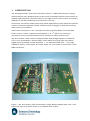
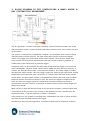
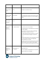
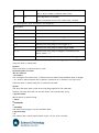
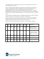
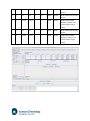
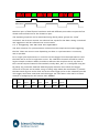
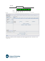
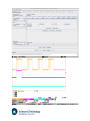
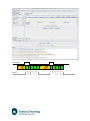
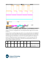
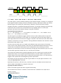
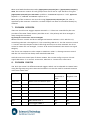
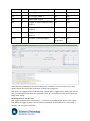
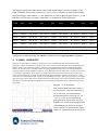
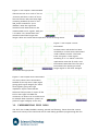
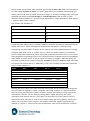
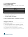
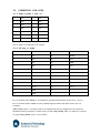
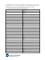
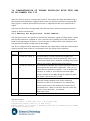
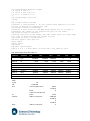
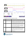
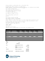
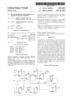
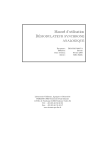
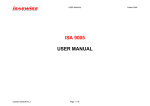
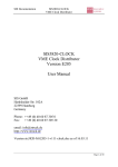
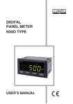
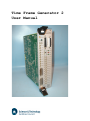
Time Frame Generator 2
User Manual
1. INTRODUCTION
The second generation Time Frame Generator (TFG2) is a VME based electronic timing
module that has been designed by the Science and Technology Facilities Council (STFC) to
support high speed time-resolved science on the light sources, and has been successfully
deployed on the SRS and Diamond synchrotrons in the UK.
In particular, the TFG2 provides all the high speed digital timing input/output for both the
control of external equipment and the synchronisation of triggers in NCD and scanning
XAFS science environments.
Time Frame resolution to 10ns is possible, with full programmability of live and dead
frames (10ns to 24hrs), repetitive frame patterns (1 to 232) either free running or
synchronous to the synchrotron beam bunch structure or other external clock.
The TFG2 utilises a wide variety of programmable drive strength digital I/O standards
(TTL, LvTTL (terminated or unterminated), LVDS, CMOS) for timing input and output,
trigger inputs (including variable threshold +/-5V 50Ω terminated, and +/-24V high
impedance inputs), user outputs and scaler inputs, all via a variety of coaxial and 2-pole
LEMO connectors.
Figure 1: The TFG2 Primary (left) and Secondary (right) Boards together with a 6U 3-slot
wide Front Panel (not shown) make up a complete TFG2 module
Time Frame outputs are available via 14-way IDC (x1), 25-way D-type (x2), VHDCI high
density connector (x3) and via the VME backplane.
With reference to Figure 1, the TFG2 hardware comprises a 6U Primary Board (master
clock, FPGA’s , memory, LVDS I/O and beam clock synchronisation) and a 6U Secondary
Board (TTL I/O, Scaler inputs, variable trigger inputs). The Secondary piggy-backs the
Primary via a multi-pin board-to-board connector. A custom Front Panel incorporating
status LED’s completes the package, creating a 6U high, triple slot width VME card
module.
Based on the VME platform, the TFG2 is designed to highly integrate with other scientific
equipment and controls typical of modern high specification light source beamlines.
2. OVERVIEW
The time frame generator (TFG) is used to control dynamic experiments using X-ray
diffraction and other techniques. Dynamic diffraction data is collected into a numbered
series of images or time frames. The TFG controls the detector system by generating a
frame number which tells the detector system into which frame to store the data. A typical
experiment will require longer time frames to study the steady states in the experiment
(before and after a change) with good counting statistics. A series of shorter frames is
then required in between to allow the experimental transition to be captured and studied
with improved time resolution. To allow for this, the length of each frame can bet set
independently.
The TFG must be synchronised to the experiment, either by the TFG triggering the
experiment or the experiment triggering the TFG. To provide for this, the TFG has 8
trigger outputs that can be programmed independently in every frame to trigger the
experiment (including a fast shutter) at any point during the sequence of time frames. The
TFG also has several external trigger inputs that can be used either to start a series of
frames or to release the unit from a paused condition. For long experiments with a
separate controller for the sample environment, the latter can be used to ensure that the
TFG and sample environment stay locked in phase.
In some experiments it is necessary to wait for periods of time with data acquisition
stopped in so called dead fames. The TFG allows one or several dead frames to be
inserted at any point in the frames sequence, with independent control of the trigger
outputs and ability to wait on trigger inputs. Data acquisition is disabled during dead
frames and the output time frame number is not incremented.
With many short time frame experiments, there are insufficient counts in a single
experimental cycle to provide analysable data. To improve the data quality, the
experiment is repeated several times (cycles) with the data being accumulated into the
same sequence of frames. The TFG contains a cycle counter to control this feature.
3. BLOCK DIAGRAM OF TFG CONTROLLING A SMALL ANGLE XRAY DIFFRACTION EXPERIMENT.
The TFG generates a master clock either internally, phased locked to another part of the
data acquisition system or phase locked to the SRS circulation clock. This controls the rest
of the system.
The system is controlled by a VME based computer. The computer writes the time frame
data into the time frame memory. The time frame data consists of the frame length,
pause, user trigger, Veto and output frame control signals. Once the time frame data,
cycle counter and control bits are initialised, the TFG is either started by software or
armed ready to be started from an external trigger.
If external start is to be used, the TFG then waits for the external trigger. If not, the TFG
starts immediately. The time frame counter, which addresses the time frame memory, is
cleared. The first time frame data is read from the memory. The frame length is loaded
into the timer down counter. The user trigger signals are output to the experiment and the
output time frame cleared to zero. Unless this is a pause frame, the timer down counter
counts down. The time frame counter is incremented to address the next location. When
the timer reaches zero the next frame is read. The new frame length is loaded into the
timer, the new user trigger signals are output and usually the output time frame is
incremented. The timer starts to count down to measure the next time frame length and
the process repeats.
When a frame is read with the last frame bit set, the Frame Counter is cleared rather than
incremented. At this point the cycle counter is decremented. If it has reached zero, the
experiment stops, if not the sequence of frames is repeated.
If the pause bit is set, instead of counting down immediately, the timer is frozen and the
TFG waits for the specified external start signal.
In addition to the time frame generator, the TFG2 includes built in calibration channels.
Internally this consists of 10 scalers with shadow memory to store the counts on a per
frame basis. There is also provision for 8 channels of 100 MHz ADC to accumulate data
into the calibration channel memory, aligned with the time frames.
4. HEADLINE FEATURES
The headline features are summarised as follows
Time Frame resolution to 10ns
Time Frame length from 10ns to 24hr
Up to 43 million Time Frames
Up to 232 cycles
6 Time Frame Output connectors with variable polarity and drive strengths
9 External Trigger Inputs including LVDS and variable threshold inputs
6 Clock Inputs including LVDS and the ability to lock to the beam clock
11 VETO, FRAMING and FRAME 0 outputs in TTL and LVDS standards
3 Combined Time Frame Outputs on VHDIC connectors
Time Frame output via VME J2 backplane
8 100MHz Scaler Calibration Channels
Provision for 8 high speed high resolution ADC Calibration Channels
6U high, 3-slot wide VME Module
5. DETAILED SPECIFICATION
The table on the following pages details the feature set and specifications of the TFG2.
The capitalised names in the Notes column eg TIME FRAME OUT 1 refers to the connector
of the same name on the TFG2 Front Panel.
TFG2 Feature
Specification
Notes
Shortest Time
10ns
100MHz on-board Xtal clock
Longest Single
109 minutes
Can merge back to back time intervals to give
Frame
Time Frame
>24hr
Time Frame
10ns
Time Frame
43 million Frames
resolution
memory
single output live frames to increase length to
Any Frame can be live or dead.
The output frame is calculated from increment
organisation
and clear signals
Back to back live frames with incrementing
output frame number are normal
The VETO signal will be asserted for 10-20ns
as the frame number changes to allow it to
settle
Multiple dead frames can be used back to back
for more complex shutter and triggering
control before a live frame
Multiple live time frames with the same output
frame number can be used to allow trigger
patterns to be generated during the live frame
Number of
Output Time
Frames
1024 Frames on 1
14-way IDC
TIME FRAME OUT 1
Ensures backward compatibility on old Scalars
Programmable drive strength.
TIME FRAME OUT [2,3]
1024 / 32768
Frames on 2 DB25
Auto sense width
10/15 bits of time frame pulse Veto and Xfer.
Programmable polarity for Veto/Xfer.
Programmable drive strength.
Typically use with RAPID1/RAPID2
1Meg – 64Meg
Frames on 3 VHDIC
LVDS COMB FRAME [1,2,3]
LVDS signalling
Programmable format with 20 to 26 bits of
time frame and balance from user or detector
control signals.
Used for HOTWAXS/HOTSAXS.
TFG2 Feature
Specification
Notes
Number of
232 cycles
4 billion
Production of
10ns resolution
43Meg Frames and spare FPGA and connector
32bit
Counts total number of internal/external starts
cycles
fine detail
timing signals
resource
to readout
detector
Start Counter
so total exposure for dead time correction is
known
External
Triggering
4 TTL external
triggers on LEMO
TRIG IN [0,1,2,3]
Inputs
‘00’
Programmable for use as start or continue
Programmable glitch rejection
Programmable polarity
1 LVDS external
trigger on 2-pole
L START
LEMO ‘00’
3 LVDS external
triggers within
LVDS COMB FRAME [1,2,3]
1 variable threshold
V TRIG 5V / 24V
VHDIC
trigger on 2 separate
LEMO ‘00’
+/-5V with a 50Ω terminated input
+/-24V with a High Impedance input
TFG2 Feature
Specification
Notes
Clock Input
1 TTL on LEMO ‘00’
CLK IN
1 LVDS on 2-pole
L CLK IN
LEMO ‘00’
3 LVDS within VHDIC
1 SR Clock on LEMO
‘00’
LVDS COMB FRAME [1,2,3]
BEAM CLK
Ability to lock the TFG2 clock to the main SR
clock for bunch and multi-bunch
synchronisation
Clock Output
1 TTL on LEMO ‘00’
CLK OUT
1 LVDS on 2-pole
L CLK OUT
LEMO ‘00’
3 LVDS within VHDIC
Veto Input
1 TTL on LEMO ‘00’
LVDS COMB FRAME [1,2,3]
VETO IN
TFG2 Feature
Specification
Notes
VETO, FRAMING
3 TTL VETO on LEMO
VETO OUT [0,1,2]
and FRAME 0
‘00’
2 TTL FRAME 0 on
LEMO ‘00’
2 TTL XFER on LEMO
‘00’
FZERO OUT [1,2]
XFER OUT [0,1]
All TTL outputs have programmable polarity
and drive strength
1 LVDS VETO on 2pole LEMO ‘00’
L VETO
1 LVDS FRAME 0 on
2-pole LEMO ‘00’
L FZERO
1 LVDS XFER on 2pole LEMO ‘00’
L XFER
1 LVDS VETO /
FRAME 0 on 4-pole
LEMO ‘00’
L GDAQ
For use with STFC Generic Data Acquisition
Cards (GDAQ)
User Outputs
8 TTL User Outputs
on LEMO ‘00’
USR OUT [0,1,2,3,4,5,6,7]
Individually programmable polarity and drive
strength
4 LVDS User Outputs
L USR [0,1,2,3]
on 2-pole LEMO ‘00’
TFG2 Feature
Specification
Notes
Combined
3 LVDS 34-pair on
LVDS COMB FRAME [1,2,3]
Output
VHDIC
Includes CLOCK, VETO, XFER, TIME FRAME (20
– 26bits wide)
Additionally, the balance of signals can include
user/detector control bits, and external
start/continue
VME J2 Output
Time Frame, VETO,
Clock and HOTWAXS
Scaler
synchronisation
VME J2
Time Frame, Veto, Clock and HOTWAXS Scaler
synchronisation routed onto VME J2 rows A
and C.
Can be bussed to GDAQ on MIDAS-50 carriers
using a VSB backplane
3.3 V signalling for compatibility with current
and later GDAQ
Calibration
Channels
8 Scaler on LEMO
‘00’
SCAL IN [0,1,2,3,4,5,6,7]
Plus live time Scaler
Plus number of acquisition counter
8 in total of which 4 are 64bit and 4 are 32bit
plus live plus hit count in ½ length burst
Individually programmable edge mode (with
glitch rejection) or count when high / count
when low
Individual lossless (edge) counting (i.e. ignores
VETO in applications such as QEXAFS)
Supported
Provision for 8 off
high speed high
resolution ADC
channels
Scaler
100MHz sampling.
TFG2 Feature
Specification
Notes
Number of
1048576
1 Meg Time frames
Provision for 8 ADC
LVDS AUXILARY IO
Performance
calibration time
frames
ADC
Performance
channels via 34-pair
LVDS cable on VHDIC
Provision for 8 channels of 50MSPS 14bit ADC
accumulating into calibration channel memory.
Gated integrations matched to 100MHz clock
cycle by linear interpolation.
Provision to use sample coincident with event
in stroboscopic mode.
Programmable averaging.
Programmable triggers for analogue signals
Hardware
VME
6U high, 3 card width, single module
Timing
Provision for 2.5ns
L USR 0
single bunch
‘00’
Platform
resolution for
stroboscopic
experiments
resolution on LEMO
USR OUT 0
6. USER PROGRAMMING
The TFG2 is a VME module supported via a Linux 2.6 driver currently for MVME2700,
MVME5100 and MVME5500. The driver is accessed by IOCTL calls which are wrapped by
libtfg2.a. For many applications the TFG is controlled by da.server which presents an ASCII
sockets based interface. The tfg commands of da.server can handle both the original
EC740 VME TFG and the TFG2. The two TFGs present the same interface to the user where
possible, with extra commands added for features supported when da.server is configure
to control a tfg2. Although every timeframe can be different, usually an experiment will be
a series of bursts of identical time frames. The tfg setup-groups command allows the tfg
to be configured as a series of groups of identical frames.
The GDA provides a graphical access to the functionality provided by da.server, with the
concepts of groups clearly accessible in the GUI.
6.1 Programming from da.server
First configure the tfg2
tfg config "etfg0" tfg2
Then, if an external trigger is required, configure it. E.g.
tfg setup-trig ttl0 start
Then setup the timing information using.
With no external start e.g.
tfg setup-groups cycles 5
10 0.0 1.0 0 0 0 0
-1 0 0 0 0 0 0
This configures the tfg to do 10 frames with no dead frames between them of length 1.0
s, with no pulse outputs and no pauses. The burst of 10 frames will be repeated for 5
cycles. In more detail each group data line is:
<num_frames> <dead time> <live time> <dead port> <live port> <dead pause> <live
pause> [<dead_tfinc> <live-tfinc>]
Note that for compatibility with the EC740, the groups contain a dead period and a live
period. For TFG2 it is acceptable and usual for the dead period to be set to length 0 and
hence ignored. Wait frames can be inserted when required by specifying a none 0 length
for the dead frame. It is also possible to have two consecutive dead frame with no live
frame between using two groups, with the live frame length set to zero in the first group.
The <dead time> and <live time> are double precision times in seconds. The port values
are a 17 bit mask coded for backwards compatibility with the EC740
Port Value
TFG2
Function
7..0
47..40
User Port 7..0
Bits
Memory Bits
15..8
39..32
Extended outputs on VETO/XFER LEMOs and Time Frame
16
31
User IRQ Marker if enabled.
Out 3. Also in LVDS Combined Time frame
Used in Alternate sources for Time Frame 3 Output.
The <dead pause> and <live pause> are coded as:
Pause Value
-1
Software Continue
0
No Pause
1
Continue on Beam Circulation trigger
2..7
Continue on ADC triggers from channel 0..5 or alternates.
8..11
Continue on rising edge of TTL Trigger 0..3
12
Continue on rising edge of LVDS Trigger LEMO
13..15
Continue on rising edge of trigger in Combined Time
16
Continue on rising edge of Variable threshold trigger
Frame Cable 1..3 .
Pause values 1..16 can be ORed with 32 (0x20) to specify triggering on the falling edge.
Then the TFG2 is started with
tfg start
In the case than an external start is used:
tfg setup-groups ext-start
10 0.0 1.0 0 0 0 0
-1 0 0 0 0 0 0
This configures the TFG2 to do 10 frames with no dead frames between them of length
1.0 s, with no pulse outputs and no pauses. The burst of 10 frames is run just once.
Then the TFG2 is armed ready for an external start with:
tfg arm
The TFG2 will then start on the next rising edge applied to TTL TRIG IN0.
In either case the TFG2 will run and the status can be read back using
> tfg read status
Which returns a quoted string
* "IDLE"
or
* “RUNNING”
or
* “PAUSED”
The time frame progress can be read back with:
> tfg read frame
* 11
This returns the current output frame*2 plus 1 if live, plus 0 if dead.
The current cycle counting down can be read back using :
tfg read lap
The tfg can be stopped with:
tfg init
Or
tfg stop
The 8 user output sit a logical 0 when the TFG2 is idle a can be programmed
independently in the live and dead frames using the 4th and 5th numbers (0..255) in the tfg
setup-groups data.
The port outputs polarity and drive strength can be set using tfg setup-port command.
The LEMO00 Veto, Frame 0 and Xfer signals can be configured using tfg setup-veto
command. The time frame outputs can be configured using the tfg setup-tfout command.
For more information see the da.server manual or type tfg ? at the da.server prompt.
6.2 Programming using the GDA
The GDA access to the above da.server commands through a series of forms. Much the
time frame group information is on the main configuration tab, with popup tables for the
details of the trigger input and output control.
When the overall experiments start button is pressed, the tfg is started or armed as
appropriate and then the status, frame and cycle are polled to generate a time bar.
6.3 Programming Concepts
Programming via the GDA or directly with da.server, the underlying concepts are identical.
The function of the Time Frame generator is to control the detector systems creating a
series of time frames and to synchronise these with the rest of the experiment, typically
the sample environment. Control of the data acquisition system is done using the
selection of LVTTL Veto, Xfer and time frame signals on the 14 way IDC and 25 way Dtype connectors and on the LVDS combined time frame ports using 68 way VHDIC
connectors. Synchronisation of the sample environment is achieved using the various user
trigger inputs and outputs, mainly LVTTL on LEMO00 connectors.
Normally there are two schemes for synchronisation. Either the TFG2 is the master and
trigger outputs are used to trigger the experiment or alternatively, the experiment
controls the timing and triggers the TFG2 via its trigger inputs. In the second case it is
possible to trigger the TFG2 either just once at the beginning of a whole experiment or to
resynchronise every lap of a multi-cycle experiment or even to retrigger every frame as
appropriate. It is also possible to combine the two schemes where the TFG triggers the
sample environment and then later waits for an external resynchronisation from the
sample environment.
6.3.1 TFG triggering the experiment.
In this case the TFG2 is the master and is started by software. The start method is set in
the GDA to software. The TFG setup groups command does not enable external start and
when the start button is pressed on the GDA, the TFG is sent the tfg start command. The
user trigger outputs or sometimes the Veto, Frame 0 and Xfer signal from the TFG2 are
used to trigger the experiment.
The user trigger outputs programmed using values in the timing group data. Logically
they are at 0 when the TFG is idle and default to remain at 0 until they get set to 1 by
setting the appropriate bit in the timing group data. Note that they can be set
independently in every frame (live or dead) provided the frame exists (has > 0 length).
Although they are logically 0 at idle and set to 1 in various frames, they can be inverted as
they leave the TFG to make signal that idle high (≈3.3V) and are asserted low (≈0 V) when
set to 1.
The Veto, frame zero and Xfer signals can sometimes be used, but are really to control the
detector systems so are used with care. See section on Veto signals.
Consider an outline muscle experiment where the TFG is used to control a fast shutter,
trigger a contraction and take a mixture of long a short time frames. The sequence is
repeated many times with a pause at the end to let the muscle rest.
USR OUT0 is used to open a fast shutter. USR OUT1 is used to trigger a contraction.
Grp
Num
Dead
Live
Dead
Live
Dead
Live
Comment
1
1
0.003
0.003
1
1
None
None
Dead Frame allows
Frm
Time
Time
Port
Port
pause
Pause
shutter to open. Live
frames takes Start point
2
1
0.0
0.001
0
3
None
None
First of dynamic
sequence with trigger
asserted and shutter
open
3
8
0.0
0.001
0
1
None
None
Dynamic 1 ms frames
4
1
0.0
0.003
0
1
None
None
Long frame at end
5
1
1.0
0.0
0
0
None
None
Long wait frame at end
with shutter open
with shutter closed
0
0
1
2
3
4
5
6
7
8
9
10
11
0
VETO
USR OUT0
USR OUT1
Note that most of the dead frames are length 0 and are removed. One is used in Frame 0
to allow the fast shutter to open. Another is used in frame 11 to allow a rest period with
the shutter closed.
Now consider the case where more complex shutter control is required to take a series of
single frames with gaps with the fast shutter closed and frames to allow the fast shutter to
open.
Grp
Num
Dead
Live
Dead
Live
Dead
Live
Comment
1
1
0.1
0.0
0
0
None
None
Dead frame with shutter
2
1
0.003
0.003
1
1
None
None
Dead Frame allows
Frm
Time
Time
Port
Port
pause
Pause
closed
shutter to open. Live
frames takes single
frame
3
1
0.1
0.0
0
0
None
None
Dead frame with shutter
4
1
0.003
0.003
1
1
None
None
Dead Frame allows
closed
shutter to open. Live
frames takes single
frame
5
1
0.1
0.0
0
0
None
None
Dead frame with shutter
6
1
0.003
0.003
1
1
None
None
Dead Frame allows
closed
shutter to open. Live
frames takes single
frame
0
0
0
1
1
1
2
2
2
VETO
USR OUT0
Note how pairs of dead frames have been used with different port values to open the fast
shutter and to allow time for the shutter to open.
The repeating sequence can be automated using the tfg setup-groups seq “name”
command, see da.server manual. An advanced set-up tab for the GDA is being considered
and suggestions will be collected over some months.
6.3.2 Triggering the TFG from the experiment.
The other schemes for synchronisation are based on the sample environment triggering
the TFG. There are various cases depending on when re-synchronisation is necessary
and/or possible.
For a single cycle experiment it is normal to use the trigger from the experiment to start
the TFG2 and to record a single time course. The calibration channels should be used to
log the sample conditions where possible to reference the sample to the X-ray data. In
this case the required external start method (usually TRIG _IN0..3) is configured using the
tfg setup-trig command. With the GDA the popup selection menu allows the trigger
source to be chosen and on either rising or falling edge. When the start button is pressed,
the GDA sends tfg arm to the TFG2 and on the next trigger pulse on the selected input the
TFG triggers and starts. Note that until the trigger, the TFG returns idle, but for a future
removal of ambiguity this will become “EXT-ARMED”.
Grp
Num
Dead
Live
Dead
Live
Dead
Live
1
10
0.0
0.001
0
0
None
None
Frm
Time
Time
Port
Port
pause
Pause
Comment
TRIG IN0
0
1
2
3
4
5
6
7
8
9
VETO
6.4
If the TFG is asked to perform multiple cycles when triggered like this, it will do so. See
‘scope trace.
Trace 1 is the VETO output, showing the burst of activity of 10 off 1 ms frames then a 10
ms dead frame. The cycle is repeated 4 times after a single trigger from the rising edge of
TTL0 on trace 2. Note the narrow “notches” in Veto as the TFG is negating veto for short
times as the frame number changes are only sometimes captured by the scope.
However, unless the clocks of the sample environment controller and the TFG2 are both
very accurate or ideally locked using the clock input or output of the TFG2, it is likely that
over multiple cycles the sample and TFG will drift out of phase and the results will
compromised. In such cases re-synchronising every cycle may be better.
A typical case where the sample environment and TFG are re-synchronised each cycle is
the stopped flow cell. The scheme is to use a pause in the first dead frame with the
continue being from an external trigger. The Start method is set to Software. When the
Start button is pressed, the GDA sends tfg start. The TFG2 starts from idle and pauses in
the first dead frame and waits for a trigger from the sample environment. When it gets the
trigger, the TFG2 runs the dynamic experiment and then, if more than 1 cycle is specified
it drops back to paused in the first dead frame, until the next trigger from the sample
environment.
Grp
Num
Dead
Live
Dead
Live
Dead
Live
Comment
1
1
10 ns
1 ms
0
0
TLL
None
Wait for external trigger
2
4
0
1 ms
0
0
None
None
Take burst of 4 frames
Frm
Time
Time
Port
Port
pause
Trig 0
Pause
then first live frame
TRIG IN0
0
VETO
0
1
2
3
4
0
0
1
2
3
4
Trace 1 shows the Veto signal with bursts of activity for a total of 5 live frames of 1 ms
duration. The burst is retriggered every cycle using the external trigger line TTL0 shown
on trace 2.
In some cases it is useful to trigger every frame. This is used extensively in the HOTWAXS
calibration code, when software intervention to change threshold values occurs between
each frame. For user experiments, it is possible that a sample changer may move a motor
and then trigger the next the frame. The issue is are all the samples to be in different
frames of a single file (useful for static experiments) or is a file to be written for each
point (useful for dynamic experiments). The TFG2 can be programmed to wait for an
external trigger in between every frame.
Grp
Num
Dead
Live
Dead
Live
Dead
Live
Comment
1
5
10 ns
1 ms
0
0
TLL
None
For each of 5 frames,
Frm
Time
Time
Port
Port
pause
Trig 0
Pause
wait for external trigger
then live frame
TRIG IN0
0
0
1
1
2
2
3
3
4
4
VETO
6.5 Veto, Xfer and Frame 0 and TTL Time Frame
The Veto signal is used to enable counting in the readout systems. Usually it is configured
to be high to enable counting and low to disable counting. With back to back live frames,
the Veto signal can remain true continuously. However, as the time frame number
changes, the value is undefined during the transition. To prevent counting into the wrong
frames the TFG2 can be set to mask transitions by negating Veto for a short time
whenever the time frame outputs change, using the command :
tfg setup-tfout mask-width <n>
N = 0 => No masking, n=1 => 10 ns before, 10 ns after n=2 => 20 ns before, 20 ns
after, n=3 => 40 ns before, 40 ns after.
The Xfer signal is provided to trigger systems such as scalers which need to copy back
data to memory at the end of a live frame. It is usually the inverse of the Veto signal, so
goes high at the end of a live frame to trigger a transfer. The hold time of the time frame
number is small here so care is required. The big difference between veto and Xfer is when
the external Veto input is used.
In some cases an event such as a spark in the detector may cause a burst of nuisance
noise counts in the readout system. If the spark can be detected before the burst of noise
counts start, the external Veto input can be configured to stop counting on all the
detectors for the duration of the noise burst by causing the Veto outputs to go low. In this
case the Xfer signal will remain low as it is not the end of frame.
The Frame Zero output pulses usually high while the TFG is Running (or Paused) and the
output time frame is a 0 in both live and dead frames. It can be used to resynchronise
remote copies of the time frame made in other data acquisition racks or can be used as a
trigger to the experiment at the beginning of the experiment.
The polarity of the veto signals and xfer signals within 25-way D-type connectors is set
using the tfg setup-tfout command.
Note that for the first 2 off TFG2 only, serial P01 and P02, the LEDs can be driven from
VETO2, XFER1 and FZERO1 by using the command
tfg setup-veto leds-on-lemos 1.
In this case these signals lose their original functionality.
Also not that from revision 2 onwards, Time Frame Out 3 defaults to an input and is
turned on using:
tfg setup-tfout enb-tf3 1
The polarity and drive strength of the individual LEMO00 Veto and Xfer signals is set
using the tfg setup-veto command
This is usually set-up in the config.cmd file that configured the detector system. The Veto
signal can be used for sample triggering or to mark frame changes in e.g. DSC data, but
with care.
6.6 Veto, Xfer and Frame 0 Extensions in Revision 2
The revision 2 onwards firmware defines additional functions for these outputs. The
LEMOs are usually driven from the internal Vero, Xfer and Frame 0 signals as described
above. Each of these LEMOS can be switched to use the extended port bits of the TFG2
memory word. Due to the partitioning of the design, this information is shared with the
upper bits of the LVDS Combined Time frame 1 & 2 so these are set to this dedicated
function. The lower 22 bits of LVDS time frame remain available as usual. The alternate
source for each of the TTL LEMO outputs can be set to normal, a fixed DC level or to be
from the extended memory bits using the command e.g.
tfg alternate-veto veto0-dc xfer0-mem veto1-normal
The drive strength and inversion can still be set with the setup-veto command. When set
to a DC level, the DC level is 0 but can be inverted using the inversion control. In effect,
the inversion control bits then gives direct control of the outputs specified as DC. The
memory bit allocation is:
Ouput
Memory
Bit
Veto(0)
32
Veto(1)
33
Veto(2)
34
Fzero(0)
35
Fzero(1)
36
Xfer(0)
37
Xfer(1)
38
6.7 TTL Time Frame 3 Extensions in Revision 2
The Revision 2 onwards firmware allows TTL Time Frame 3 (25 way D-type) to be used as
an input or output and defines alternates sources when used as an output. To remove the
problem of bus contention, this connector now defaults to an input at power and must be
enabled as an output when required using:
tfg setup-tfout enb-tf3 1
Normally the cable carries 10 or 15 bits of time frame Veto and Xfer. The upper 5 bits of
time frame are enabled by a width sense pin which is pulled high on the TFG2 but
grounded by old 10 bit only loads such as the RAPID2 correlator.
Alternate modes are configured using:
tfg alternate-tf3
The connector is controlled in 4 sections: Lower 10 time frame bit TF9..0, upper 5 bits
TF14..10, Veto and Xfer. Each bit can be set to normal (from the internal time frame
counters and Veto/Xfer signals), Fixed DC 0 with inversion control to allow 1s to be set
and from TFG memory bits. There are only 8 “spare” memory bits in the TFG setup word
so the memory bits also can drive other pins. Care must be taken that this is accounted
for. In situations where multiple devices are connected, but only a few are used at one
time, unwanted side effects must be prevented by either disabling other hardware from
software or using the fixed DC options to disable the other uses of the pins. To try to
make optimum use to the outputs, the memory bit allocation is some fragmented.
TF3 Bit
Memory Bit
0
38
1
39
2
40
3
41
4
42
5
43
6
44
7
45
8
46
9
47
10
32
11
33
12
34
13
35
14
36
Veto
31
Xfer
37
To allow The lower 10 time frames to continue to be used as time frame in hybrid modes,
the lower 10 bits overlap the all the User Port Bits 47..40 as these are usually used for
trigger outputs via the LEMO00s. Veto and Xfer similarly overlap bits which may already be
used. The upper 5 bits use Memory 32..36 which are generally available for extended
functions.
When used in normal mode using [upper|lower|veto|xfer]-normal there is no inversion
option for the time frame bits and the Veto and Xfer are controlled via the tfg setup-tfout
command as usual.
When used with the alternate modes [upper|lower|veto|xfer]-dc or [upper|lower|veto|xfer]-
mem, the inversion control of each group of bits can be set on a per bit basis using the
[upper|lower|veto|xfer]-inv <bit-mask> qualifiers. So lower-inv expects 0..1023, upper-inv
expects 0..31, veto-inv and xfer-inv expects 0 or 1.
When any of the 4 sections are set to dc using [upper|lower|veto|xfer]-dc, the value is
specified by the inversion control bit, so these outputs can then be controlled directly by
software.
7. TRIGGER OUTPUTS
There are 8 LVTTL user trigger outputs USR OUT 0..7. These are controlled by the user
port bits of the time frame memory word bit 40..47. The polarity and drive strength is
setup using the command:
tfg setup-port <inversion> <drive-strength>
Where inversion-control and drive-strength are bitwise numbers 0..255 with bit 0 (1)
controlling USR OUT 0 through Bit 7 (128) controlling USR OUT 7. For the inversion control
a 1 means invert the output so that it idles high and drop to 0 when asserted. For drive
control 0 means full rive strength, 1 means 50 Ω series terminated. See section on Signal
Integrity.
The first 4 user outputs are also output as LVDS on L USR0..3, sharing inversion control
with the TTL versions but always with standard LVDS drive.
Until the inversion control part of GDA is written, the current config script on i22 sets
signal USR OUR 0..3 as normal, series term, USR OUT 4..7 Active low, series term.
8. TRIGGER INPUTS
The TFG2 has a total 16 different external triggers which can be selected as external start
using the tfg setup-trig start command and which can also be used for external continue
in the time frame data.
Qualifier
Number
Source
Requires
Threshold in
Volts
Accepts
Deglitch Time
beam-circ
1
Beam Clock Circulation input
No
No
adc0
2
ADC Board Chan 0
Yes
No
adc1
3
ADC Board Chan 1
Yes
No
adc2
4
ADC Board Chan 2
Yes
No
adc3
5
ADC Board Chan 2
Yes
No
adc4
6
ADC Board Chan 4
Yes
No
adc5
7
ADC Board Chan 5
Yes
No
ttl0
8
TTL Trigger LEMO 0
No
Yes
ttl1
9
TTL Trigger LEMO 1
No
Yes
ttl2
10
TTL Trigger LEMO 2
No
Yes
ttl3
11
TTL Trigger LEMO 3
No
Yes
lvds
12
LVDS LEMO Trigger
No
Yes
ctf1
13
Trigger in LVDS Combined Time
No
Yes
ctf2
14
Trigger in LVDS Combined Time
No
Yes
ctf3
15
Trigger in LVDS Combined Time
No
Yes
vthres
16
Variable Threshold Trigger
Yes +/- 5V at
Yes
Frame 1
Frame 2
Frame 3
50 Ω input
Generally any combination of external starts and continues can use used, but ctf1 and
vthres cannot be used at the same time as they share resources.
The beam-circ trigger locks to the SR clock input to give a trigger which allows the TFG to
run synchronised to the SR beam circulation clock. It is available once the clock input has
been setup using:
tfg setup-clk-in sr vco-div <nn>
The trigger position takes some delay (…) from the rising edge of the beam clock input.
The effective trigger position can be rolled to anywhere in the input clock cycle using a
counter, set using the command:
tfg sr-clk-delay <n>
The delay n is in clock cycles (nominally 10 ns, but actually dependent on the input clock
frequency and VCO divide ratio). The value n can be 0 to vcodiv – 1. The measured
circulation time can be measured using:
tfg sr-clk-delay measure
This should always return the vco-div ratio minus 1 when used in locked mode.
The ADC trigger 0..5 will only be available once the Analogue input card has been
designed and built. They will take a threshold voltage and optionally DSP filter options,
including low pass filters and differentiation with zero cross discrimination.
The TTL triggers 0..3 are the usual user trigger inputs. They have an optional de-glitch
circuit which can be setup to reject glitches less than the specified width, which can be 10
ns to 2.55 µs. When this is used, the fixed delay from trigger in to trigger out is extended
by the de-glitch time.
The LVDS input is on the 2 pin LEMO00 L START and optionally has the de-glitch circuit.
The LVDS combined time frame cables 1..3 include an external start signal to allow the
TFG to be synchronised to a detector system, rather than the experiment. Again de-glitch
is available
The Variable threshold input is has two connectors feeding one comparator. One input
supports signals of +/- 5V and provides a 50 Ω termination. The threshold is specified in
volts referenced to this input.
The other input has an attenuator so it provides a higher input impedance and covers a
+/- 25 V range. The threshold must be scaled by 25/5 = 5 times. So for a 10 V threshold
on the +/- 24V input, the threshold referred to the 5 V input is set to 10/5 = 2. V and the
25 V input is used.
The thresholds and deglitch time are specified using the command:
tfg setup-trig vthres debounce <time in seconds> threshold <volts>
Using the GDA form, specify the thresholds in volts and the de-bounce time in µs.
The threshold and de-bounce can be specified independently for each trigger source and
are used for external start, external continue and also external pause functions.
To set the de-glitch time on TTL0 and to mark TTL0 as the source for external start:
tfg setup-trig ttl0 start debounce 1.0e-6
To setup the de-glitch time ready for use as external continue, but not to use as external
start:
tfg setup-trig ttl0 debounce 1.0e-6
8.1 Alternate Trigger sources.
The version 2 firmware allows alternate sources for 8 of the least used triggers. The
alternate trigger can be used for any of the trigger functions, (Start, pause or continue)
and are enabled using the alternate qualifier on the tfg setup-trig command. E.g.
tfg setup-trig adc0 start alternate 2
The triggers which have alternates are the 6 ADC based triggers and the Triggers in the
LVDS Combined Time Frame connectors 2 and 3. (CTF1 is already re-used as the variable
threshold trigger). Alternates 0..7 exist. Alternate=0 is the original trigger source. 1..6 are
defined in the revision 2 firmware. Alternate 7 is available for future expansion.
Trigger
name
Alt0
Alt1
Alt2
Alt3
ALt4
ALt5
Alt6
Alt7
adc0
ADC(0)
TF3_OUT0
TF3_OUT8
SCAL0
TF3_OUT2
TF3_OUT11
SCAL4
Spare
adc1
ADC(1)
TF3_OUT1
TF3_OUT9
SCAL1
TF3_OUT3
TF3_OUT12
SCAL5
Spare
adc2
ADC(2)
TF3_OUT2
TF3_OUT10
SCAL2
TF3_OUT4
TF3_OUT13
SCAL6
Spare
adc3
ADC(3)
TF3_OUT3
TF3_OUT11
SCAL3
TF3_OUT5
TF3_OUT14
SCAL7
Spare
adc4
ADC(4)
TF3_OUT4
TF3_OUT12
SCAL4
TF3_OUT6
TF3_OUT15
SCAL0
Spare
adc5
ADC(5)
TF3_OUT5
TF3_OUT13
SCAL5
TF3_OUT7
TF3_OUT16
SCAL1
Spare
cft2
CFT2
TF3_OUT6
TF3_OUT14
SCAL6
TF3_OUT0
TF3_OUT8
SCAL2
Spare
ctf3
CTF3
TF3_OUT7
TF3_OUT15
SCAL7
TF3_OUT1
TF3_OUT9
SCAL3
Spare
The alternate triggers come from the Scaler inputs and the TTL Time Frame Output 3
(Configured as input by using the enb-tf3 0 qualifier from the tfg setup-tfout command)
9. SIGNAL INTEGRITY
The TFG2 can generate timing signal to a resolution of 10 ns and below with jitter levels even less when
operating in a phase locked mode. To preserve the accuracy of these signals when they are transmitted either to
detector system or to sample environment controllers, two high performance electrical standards have been
chosen. For ultimate accuray, a limitted number of signals have been brought out in Low Voltage Differential
signalling (LVDS) on two pin LEMO00 connectors, on the left hand side of the front panel. The signal names start
L to signify the LVDS nature. In the future any sample environments that warrant the low jiter, low time walk
nature of these high accuracy signals should be designed with LVDS inputs. However, the majority of system
will use the more conventional LVTTL signals on coaxial LEMO00 connectors. These are driven from 3.3 V supply
high drive LVTTL outputs with software programmable series termination. The ‘scope screen dumps below show
the need for care with these high bandwidth drivers and show the effectiveness of the series termination when
appropriate.
Figure 3: 10 ns operation.
This demonstrates operation with 10
ns time frames. The horizontal axis is
10 ns/division. The TFG has been
programmed with a series of 10, 10
,10, 10, 10, 20 & 10ns live frames
giving the veto signal (top). The user
outputs 0 to 2 have been programmed
independently per frame to give the
lower 3 traces. To preserve the signal
at the eTFG and termianted into 50 Ω at the scope.
shape, all signals were set to full drive
Figure 4: User output 0 unterminated.
These traces are on a scale of 100 ns
/division and show a series of 50 ns
live time frames with Veto (top) high
(counting enabled) for 400 ns and
USR_OUT0 asserted for 50 ns
(bottom). Note the significant
overshoot and undershoot on the
unterminated LVTTL signals, with just
2 m cables. This undershoot and
overshoot would be longer with
longer cables and could distrub operation of the receiving device.
Figure 5: User output 0 series
terminated.
In these traces USR OUT0 has been
switched to 50 ohm series terminated
under software control. The lower
trace now gives a clean signal
switching to 3.3 V, which is ideal for
applications were the far end is not
terminated. Note that if the far end is
termianted, this would give a half
would then be appropriate.
height signal so full drive strength
Figure 6: Veto output series terminated
This trace shows series termination
enabled for the top trace (Veto) again
giving good signal integrity for radial
wired signals going into high
impedance inputs. Note that the
enhanced TFG provides 3 copies of the
LVTTL Veto signal on LEMO 00
connectors to allow it to be radial wired
to multiple data acquistion systems to
preserve signal integrity in this way.
10. INTERPRETING TFG2 LEDS
The TFG2 has 3 LEDs labelled counting, paused and framing. These show the current
status and activity of the TFG2 and can be used debug problems programming the TFG.
Time frames can range from 10 ns to hours, so making the lights visible under all cases
requires some care. The light driving code stretches the times the LEDS are on so that for
short events are visible, but the stretch is short enough that for bursts of short time
frames, the LEDS can be seen to flicker.
•
The Counting LED is lit whenever the TFG is driving the Veto signals to enable
counting. The LED is off when the TFG is idle and comes on during live frames.
•
The Pause LED is lit when the TFG is sitting in a pause state wait for either a software
or hardware continue.
•
The Framing LED flashes whenever the output time frame changes, showing a time
frame sequence is running.
Generally the TFG will sit with all the LEDs off until the start command is sent The
Counting LED will then turn on and the Framing light will Flash every time frame.
For experiments using an external trigger for start, the LEDs are off when the TFG2 is idle
and do not change when the arm command is sent. When the external start is applied, the
Counting LED will usually come on and the Framing light will flash every frame.
If the experiment uses pause frames, the Pause light will be on when the TFG is waiting for
the software or external continue.
When trying to debug problems with a TFG triggering setup, the usual problem is that
either that it does not start/continue or it apparently locks out and never finishes.
For the TFG2 not to start from idle either the software or hardware start is not enabled or
the hardware start is missing. In this case it will generally sit with all the LEDS off.
If the TFG2 is being used with a pause and continue (often in the first dead frame to
resynchronise each cycle) then if the (usually external) trigger is missing then the TFG2
will sit with just the paused light on.
In either case, once it gets a trigger there should be a burst of activity on the counting and
framing lights.
If by user error there is an unintentionally long live frame, then it will sit with counting on
and no other lights. If it is progressing normally, the counting light will be on with flashes
on the Framing light when it changes frame. So this type of apparent lock out is
detectable.
If there is an unintentional extra pause request, then it Paused light will come on, again
indicating this kind of error.
At the end of the experiment, all the lights will go out and the software should read the
idle state from the TFG2 status register. The GDA should then return to a state allowing
data to be saved or the next experiment started. The TFG2 will also sit with all the lights
out during with an (un)intentionally long dead frame, but with only 3 LEDS there is a limit
to what can be coded. Generally, at the end of the experiment all the lights will go out.
If the GDA does not notice and locks out, the fact all the lights on the TFG are out and the
GDA has not returned to ready is a useful indication. At this point I would look at the
da.server log window and see whether the GDA has polled the TFG status (if not, why not)
and has da.server correctly reported that the TFG is idle (again if not, why not).
11. CALIBRATION CHANNELS
The TFG2 contains a calibration channel memory which accumulates data from a live time
scaler, 8 internal user scalers and when delivered from the ADC calibration channels. The
combination of scaler and ADC data can be selected in various modes. This data is
continually (every 2 µs) accumulated into the calibration memory and any remainder is
also accumulated at the end of every time frame. The calibration channel memory usually
operates the read-add-write bursts accessing 16 locations of 64 bits. This takes approx.
43 clock cycles of 100 MHz to accumulate so this sets a lower limit on the time frames
that can be used with the calibration channels. Allowing some margin for refresh and a
small amount of readout, the shortest continuous time frames should be 500 ns. Unlike
the EC738 scaler, the TFG2 calibration channels do not need a dead frame between live
frames to trigger data accumulation as it has access to the Time Frame update signals
internally.
For faster time resolution the calibration channel can be operated to access only the first 8
64 bit locations with reduced channels or word sizes. This is accumulated in 27 clock
cycles so limits time frames to about 340 ns allowing for refresh and readout. Note that if
the data is not read out during acquisition, the time frames could be reduced slightly.
Also, FIFOs are used so a small number (to be determined but of order 8..16) could be
readout out with reduced time frames provided there is a gap for the accumulation engine
to catch up.
Generally the TFG2 will be operated in 64 bit scaler mode using
tfg setup-cc-mode scaler64
In this mode the TFG2 outputs 9 rows of calibration channel data. The first is the Live time
accumulated into each frame, measured in clock cycles of the 100 MHz clock. The
remaining 8 rows are Scaler 0..7.
Each scaler channel can run in one of four modes ( 8 for revision 2 onwards) using the
command:
tfg setup-cc-chan …..
edge
Normal mode counting rising edge of input
level
Count at 100 MHz while input is High
inv-level
Count at 100 MHz while input is low
debounce
Count rising edges of input but with a de-glitch filter of 0 to 2.55 µs
vetoed-
Count at 100 MHz while associated memory bit and input is high
Vetoed-
Count edges while associated memory bit is high
Time-veto
Count While associated memory bit is high (ignore input)
level
egde
vetoed-
debounce
Count de-bounce filtered edges while associated memory bit is high
Under the GDA, by default the scaler channels are set to rising edge mode and can be
changed by editing the xml file.
Usually the calibration channels respect the same veto and time frame signals as output by
the TFG2 to the rest of the DAQ systems. However, each scaler channel can be set to
ignore the veto signal so that all pulses are counted. In particular, if a pulse occurs as the
mask transition code has disabled counting as the time frame changes, this count will not
be lost in the internal calibration channels. This is intended to count pulses from an
encoder for quick scanning EXAFS.
The TFG2 hardware also has provision to calculate the time frame seen by the calibration
channels separately from the output time frame. The idea is that the calibration channels
could:
•
Split each output time frames into say 10 sub-frames each to check that the sample is
changing only a small amount during a single time frame.
•
Not reset to zero at the end of each cycle so that the calibration channel data for each
cycle of a cyclic experiment is kept separate, allowing confirmation that each cycles is
similar.
Given the TFG2 supports 1 Meg calibration channel time frames, whereas RAPID 2D 2d is
limited to 1024 time frame, there is plenty of scope to create extra calibration sample data
in either way. However, both these suggestions have wider implications for the data
processing, file formats etc and require detailed consideration before they are supported
by da.server and the GDA and DREAM.
Under da.server the calibration channel are supported as a unified read path, opened by
tfg open-cc (AFTER the setup-cc-mode command). The data can be in a mixture of 32 and
64 bit formats. It is recommended that the data is read back as 32 bit floats, with
da.server responsible for type conversions. The 64 bit integer data will loose some
precision when returned as 32 bit float, but will not wrap round causing gross errors.
11.1 Revision 2 Scaler Extensions.
The revision 2 Scaler extensions help address the needs of experiments where external
equipment controls some of the timing and possibly the integration time. The schemes
allow an output frame to be split into several sub-frames or phases. To do this, the
extended Time Frame increment options are used in the TFG set-up groups so that the
time frame only increments once per set of sub-frames. Generally this is done by adding 0
0 to the end of the groups lines for all but the first sub-frame of a frame to hold the TF
counter. All the sub-frames are defined as live frames so the scalers can count.
The TFG is programmed with pauses in various sub-frames to force the TFG2 to wait for
the external equipment. To allow the actual time in each phase to be timed, memory bits
in the extended port fields can be used to enable some of the scalers in these pause
frames. Using the time-veto option, the scaler can then be used to time how long the TFG
stayed in that pause frame. This would be done using the time-veto option on one channel
of scaler using tfg setup-cc-chan. To count I0 only during one of these pause frames, the
memory bit can be used to enable counting of edges or de-bounced edges only during the
specified sub-frame using vetoed-edge or vetoed-debounce mode on one or a few
channels. Note allocation of 1 memory bit to the bottom 5 scaler channels to allow several
I0 channels plus a timer channel.
The memory bit allocation is:
Scaler Channel
Memory Bit
0..4
32
5
35
6
37
7
39
These bits are shared with the alternate use of VETO0, FZERO0 and XFER0. The suggestion
is that the other LEMOs (VETO1,2 XFER1, FZERO1) would be allocated to alternates sources
before these last 3, often making these memory bits available for masking timing.
Considering synchronisation schemes of this nature, discussed “Demonstration of timing
protocols with TFG2 and hi re-camera for I12”, there are various choices as to when to
wait for the external apparatus with a pause and accept the variation in time, or to wait for
fixed (hopefully long enough time) in the TFG and time the external signals to see whether
it has fitted. To allow choice of use of signals as scalers or triggers, alternate inputs are
provided on each of the 8 scalers using the alternate qualifier on setup-cc-chan. Alternate
0 is the normal input Scaler 0..7. Alternates 1 and 2 are currently implemented. Alternate
3 is for future expansion.
Scaler
Scaler 0
Scaler 1
Scaler 2
Scaler 3
Scaler 4
Scaler 5
Scaler 6
Scaler 7
Alt 0
Scaler 0
Scaler 1
Scaler 2
Scaler 3
Scaler 4
Scaler 5
Scaler 6
Scaler 7
Alt 1
TTLTRIG 0
TTLTRIG 1
TTLTRIG 2
LVDSTRIG
TF3Out 4
TF3Out 5
TF3Out 6
TF3Out 7
Alt 2
TF3OUT 8
TF3OUT 9
TF3OUT 10
TF3OUT 11
TTLTRIG 0
TTLTRIG 1
TTLTRIG 2
TTLTRIG 3
Alt 3
Spare
Spare
Spare
Spare
Spare
Spare
Spare
Spare
Splitting the time frames into sub frame and pausing the TFG at various points keeps the
TFG and external apparatus in step. Using the veto-edge mode etc it is then possible to
count I0 during specified sub-frames. However, pausing does lead to timing uncertainty.
Alternatively, the TFG can run without pausing with a signal specifying the actual
acquisition time input to the TFG. This signal can be used as an extra veto to time the
actual acquisition time and to allow I0 to be vetoed using the correct gating. These extra
vetoes can come from various inputs. Two internal extra veto signals are provides for
channel 0..3 and 4..7. The use of the associated extra-veto can be enabled on a channel
by channel basis using the extra-veto qualifier on setup-cc-chan. The two veto signals are
set-up using the tfg setup-cc-extra-veto command. E.g.
tfg setup-cc-extra-veto chan0-3 veto-scal 7
tfg setup-cc-extra-veto chan4-7 veto-trig0 inv-veto
This pair make the channel 0..3 extra veto from Scaler 7, high to count and the Channel
4..7 veto from TTL 0, low to count.
tfg setup-cc-extra-veto chan0-3 chan4-7 veto-tf3 2
This sets up both channel 0..3 and 4..7 to use TTL Time frame 3 (as input) bit 2.
Input
Qualifier
Scaler 0..7
veto-scal 0..7
TTL trigger 0..3
veto-trig 0..3
TTL Time Frame 3 TF bit 0..14
veto-tf3 0..14
TTL Time Frame 3 TF Veto Pin
Veto-tf3 15
The effective veto on a scaler is the logical and of:
•
•
•
The TFG Live signal (unless ignore-veto specified)
The associated memory bit (if vetoed-[edge|level|debounce] is specified)
The extra hardware veto described here.
12. VERSION 5 UPDATE (PROVISONAL)
Work on I12 has identified the need to wait until the later of 2 systems have gone busy
and back to free. In this case it is a motor move and camera readout. Very few TFG2 has
this firmware at the moment. Da.server should refuse the enb-level command below if the
tfg2 is not of the correct release.
Currently a combined ORed trigger is made from TTL trigger 0 and 1 Ored together to
make alternate trigger 7 for ADC0 trigger.
tfg setup-trig adc0 alternate 7
Then use the pause bit in a tyiming group to look for this going low by setting the pause
field to 2+32 in the dead or live pause.
The continue signals are usually edge active. There is now the option to turn on level
sensitive mode. In this way the system could wait for e.g. several busy signals to be low by
using a series of frames, 1 for each signal to be tested.
This mode has an overall enable using tfg set-trig enb-level 1
Then in an individual frame, level mode is enabled by setting by 15 (32768) in the
associated port word. Note this bit has other uses as well, hence the over all enable. The
alternate uses of this bit should be considered mutually exclusive.
13. CONNECTOR PIN-OUTS
13.1 Time frame 1 IDC 14
1
TF0
2
TF1
3
TF2
4
TF3
5
TF4
6
TF5
7
TF6
8
TF7
9
TF8
10
TF9
12
GND
14
GND
11
13
GND
This is always configured as an output.
13.2 25-way D-type
1
TF0
14
GND
2
TF1
15
SENSE
3
TF2
16
TF10
4
TF3
17
GND
5
TF4
18
TF11
6
TF5
19
GND
7
TF6
20
TF12
8
TF7
21
GND
9
TF8
22
TF13
10
TF9
23
GN D
11
VETO
24
TF14
12
XFER
25
13
GND
For 10 bit time fame SENSE is connected to ground and the TFG2 drives TF10..14 to 0.
For 15 bit time frame, SENSE is Open (pulled high by TFG2) and TFG2 drives TF0..14
normally,
TIME_FRAME_OUT2 is usually used as an output but can be configured as an input for
loopback testing. However is shares TF[9..0] with TIME_FRAME_OUT1 so when it is used as
an input TIME_FRAME_OUT1 is not usable.
TIME_FRAME_OUT3 is usually used as an output but can be configured as an input for loop
back testing and for use as extended trigger inputs. It has independent connections to the
master FPGA so can be used as an input without disturbing the other outputs.
13.3 LVDS Combined Time frame connectors
1
Clock Out
2
Clock In
3
TFG Enb
4
Xfer
5
TF0
6
TF1
7
TF2
8
TF3
9
TF4
10
TF5
11
TF6
12
TF7
13
TF8
14
TF9
15
TF10
16
TF11
17
TF12
18
TF13
19
TF14
20
TF15
21
TF16
22
TF17
23
TF18
24
TF19
25
TF20
26
TF21
27
TF22
28
TF23
29
TF24
30
TF25
31
DetControl3
32
DetControl4
33
DetControl5
34
ExStartIn
These connectors are driven from 2 secondary FPGAs and so there is limited connectivity.
LVDS_COMB_FRAME1 and LVDS_COMB_FRAME 2 are driven from secondary FPGA1. They
usually have the same format as they share all 31 signals (TFGENB, XFER, TF[0..25],
detControl[3..5]).
LVDS_COMB_FRAME 3 is driven independently from the main FPGA and can be configured
as an input for loopback testing or other expansion.
14. DEMONSTRATION OF TIMING PROTOCOLS WITH TFG2 AND
HI RE-CAMERA FOR I12
There are various ways to consider this protocol. This system has been emulated using a
two channel pulse generator triggered by the TFG user out(7) to make the acquiring and
busy signals. A second asynchronous 250 kHz is supplied to Scaler 0 to represent an I 0
signal.
The time may be orders of magnitude from the real times, but the concepts translate to
slower or faster time domains.
14.1 Pausing for Acquisition, fixed readout.
The first version uses TFG pauses to wait for the acquisition signal and then allows a fixed
time for the readout to complete in. This runs the risk of getting out of step, but helps
preserve timing integrity if there is a lot of variation in readout time. The acquisition and
busy periods are timed to keep track of the length.
The TFG is configured with several time intervals per output frame, with the extend option
used to hold the time frame so it increments once per group of time intervals.
Frame
Tfg group
0
1 0 10e-9 0 128 0 8
section
0
The first phase is a Live frame which triggers the
camera and waits for it to start acquiring. This is a 10
ns Live frame with port 7 asserted, pausing until rising
edge of TTL Trig(0). Default time frame actions.
1
1 0 10e-9 0 256 0 40
00
The 2nd phase shadows the camera acquisition time by
pausing until the acquisition signal falls. This is a Live
frame with the extend port signal = 256 to enable with
scalers 0..4. Scaler 0..3 are used to count I0 edges.
Scaler 4 counts at 100 MHz during this period to time
the frame. The time frame is held.
2
1 0 1e-3 0 2048 0 0 0
0
The final phase is a live frame of fixed 1 ms duration to
allow the camera readout. Live frame measuring
duration in scaler 5 for fixed time 1ms. During this
period scaler input 5 and enabled by memory bit 35
(extended port =2048) to measure the busy time and
check it is less than the 1 ms allowed.
Hold time frame.
The test script is:
# Trig signal is from User Port 7 (bit mask 128)
# Acquiring signal comes in to TTL Trig 0
# Busy Signal is in Scaler 5 masked by mem bit 35 enabled by port=2048
tfg config "etfg0" tfg2
tfg setup-groups sequence "seq0"
1 0 10e-9 0 128 0 8
1 0 10e-9 0 256 0 40 0 0
1 0 1e-3 0 2048 0 0 0 0
-1
tfg setup-groups cycles 10
5 seq0
-1
tfg setup-cc-mode scaler64
# Channel 0 (and possible 1..4) are vetoed using memory bit 32 and
# count I0 during the acquisition time.
tfg setup-cc-chan 0 vetoed-edge
# Channel 4 uses counts at 100 MHZ while memory bit 32 is high so
# measures the length of the acquisition part of the frame.
tfg setup-cc-chan 4 time-veto
# During last part of the frame, the TFG counts while the busy input
# is true to show how long the system is busy.
tfg setup-cc-chan 5 vetoed-level
set-func "path" "tfg open-cc"
clear %path
enable %path
tfg start
tfg wait ignore-pause
read 0 0 0 9 1 6 from %path to-local-file "i12_demo/v1.txt"
The data output from the scaler is:
Column1
Chan 0
Chan 1
Chan 2
Chan 3
Chan 4
Chan 5
Chan 6
Chan 7
Column2
Live
I0
Acquire
Busy
TF 0
1503950
1238
0
0
0
500000
296320
0
0
TF 1
1503950
1236
0
0
0
500000
296320
0
0
Num
cycles
Clk
Live
10
1.00E+08
= Start+acquire+1ms
I0
Acquire
Count
= 500 us of 247 kH x 10
cycles
=500 us x 10 cycles
Busy
=300 us x 10 cycles
TF 2
1503950
1240
0
0
0
500000
296320
0
0
0.015
1.50E+0
6
1235
5.00E-04
5.00E+0
5
3.00E+0
5
TF 3
150395
0
1236
0
0
0
500000
296320
0
0
TF 4
TF 5
150395
0
1239
0
0
0
500000
296320
0
0
0
0
0
0
0
0
0
0
0
Trig
Acquire
Readout
14.2 Pausing for both Acquiring and Busy
Frame
section
0
Tfg group
1 0 10e-9 0 128 0 8 -
1 -1
The first phase is a live frame which triggers the camera
and waits for it to start acquiring. This is a 10 ns live
frame with port 7 asserted, pausing until rising edge of
TTL Trig(0). Default time frame action in live frame.
1
1 0 10e-9 0 256 0 40
00
The 2nd phase shadows the camera acquisition time by
pausing until the acquisition signal falls. This is a Live
frame with the extend port signal = 256 to enable with
scalers 0..4. Scaler 0..3 are used to count I0 edges.
Scaler 4 counts at 100 MHz during this period to time
the frame. The time frame is held.
2
1 0 10e-9 0 2048 0
41 0 0
The final phase is a live frame which waits for readout
to complete. The frame pauses waiting for the falling
edge of busy.The duration of the frame is timed in
scaler 5 enabled by memory bit 35 (extended port
=2048)
Hold time frame.
# Trig signal is from User Port 7 (bit mask 128)
# Acquiring signal comes in to TTL Trig 0
# Busy Signal is in Scaler 5 masked by mem bit 35 enabled by port=2048
# Now used as alternate 3 adc 1 = trigger 7
tfg config "etfg0" tfg2
tfg setup-trig adc5 alternate 3
tfg setup-groups sequence "seq0"
1 0 10e-9 0 128 0 8
1 0 10e-9 0 256 0 40 0 0
1 0 500e-6 0 2048 0 39 0 0
-1
tfg setup-groups cycles 10
5 seq0
-1
tfg setup-cc-mode scaler64
tfg setup-cc-chan 0 vetoed-edge
tfg setup-cc-chan 4 time-veto
# Now channel 5 times time phase 2 of the frame while waiting for the
# busy signal and then the 500 us that was added afterwards in this
# case(to make the pulse generator happy).
tfg setup-cc-chan 5 time-veto
set-func "path" "tfg open-cc"
clear %path
enable %path
tfg start
tfg wait ignore-pause
read 0 0 0 9 1 6 from %path to-local-file "i12_demo/v2.txt"
Column1
Chan 0
Chan 1
Chan 2
Chan 3
Chan 4
Chan 5
Chan 6
Chan 7
Column2
Live
I0
Acquire
Busy
Num
cycles
Clk
Live
TF 0
TF 1
TF 2
TF 3
1300440
1300440
1300440
1300440
1238
1238
1238
1239
0
0
0
0
0
0
0
0
0
0
0
0
500000
500000
500000
500000
796490
796490
796490
796490
0
0
0
0
0
0
0
0
I0
Acquire
10
1.00E+08
= Start+acquire+0.5ms
Count
= 500 us of 247 kH x 10
cycles
=500 us x 10 cycles
Busy + 500 us pause
=(300+500) us x 10 cycles
0.013
1.30E+06
1235
5.00E-04
5.00E+05
8.00E+05
TF 4
TF 5
1300440
1239
0
0
0
500000
796490
0
0
0
0
0
0
0
0
0
0
0
With this scheme the TFG waits on the camera 3 times, It should never get out of step, but
the timing accuracy of the experiment is very dependant on the time the camera takes.
However, the total live time scaler (first row of scaler output) can be accumulated to give a
time axis.
14.3 No Pausing
One could also suggest a protocol where the TFG does not wait for the camera at all. It
carries on and assumes all is OK. The acquiring and busy signals are timed directly using
the level mode of the scalers, to confirm success. The acquiring signal is also used to veto
the I0 channel(s).
# Trig signal is from User Port 7 (bit mask 128)
# Acquiring signal comes in to TTL Trig 0
# Busy Signal is in Scaler 5
# No pausing in this version just 100 us of trig high, 1.4 ms trig
low.
# Time stages in various scalers using alternate scaler inputs
tfg config "etfg0" tfg2
tfg setup-groups sequence "seq0"
1 0 100E-6 0 128 0 0
1 0 1.4E-3 0
0 0 0 0 0
-1
tfg setup-groups cycles 10
5 seq0
-1
tfg setup-cc-mode scaler64
tfg setup-cc-extra-veto chan0-3 chan4-7 veto-trig 0
# Channel 0 Count I0 using extra veto
tfg setup-cc-chan 0 edge extra-veto
# Channel 4 times TTL trigger 0 as alterante 2
tfg setup-cc-chan 4 level alternate 2
# Channel 5 can time the Busy signal directly
tfg setup-cc-chan 5 level
set-func "path" "tfg open-cc"
clear %path
enable %path
tfg start
tfg wait ignore-pause
read 0 0 0 6 1 9 from %path to-local-file "i12_demo/v3.txt"
Column1
Chan 0
Chan 1
Chan 2
Chan 3
Chan 4
Chan 5
Chan 6
Chan 7
Num
cycles
Clk
Live
Column2
Live
I0
Acquire
Busy
TF 0
TF 1
TF 2
TF 3
1500000
1500000
1500000
1500000
1238
1238
1238
1238
0
0
0
0
0
0
0
0
0
0
0
0
500000
500000
500000
500000
300000
300000
300000
300000
0
0
0
0
0
0
0
0
I0
Acquire
10
1.00E+08
= Fixed 1.5 ms
Count
= 500 us of 247 kH x 10
cycles
=500 us x 10 cycles
Busy
=300 us x 10 cycles
0.015
1.50E+06
1235
5.00E-04
5.00E+05
3.00E+05
TF 4
TF 5
1500000
1238
0
0
0
500000
300000
0
0
0
0
0
0
0
0
0
0
0