1
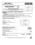
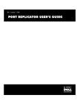
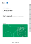
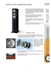
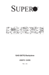
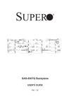
Standard Flush Mount Installation Manual Flush Mount Systems Schletter Inc. offers a wide array of solutions for flush mount photovoltaic (PV) applications suitable for nearly any environmental condition. Every system is designed for strength and ease-of-installation using high quality products. Features • Conforms to UL SUB 27031 • Certified to ULC/ORD Std C1703 • Fire class resistance rating: Class A when used with Types 1 and 3 photovoltaic modules only2 • Flexible design • Modular components • Industry leading installation times • Electrically bonded unit3 • Included Rapid2+™ grounding module clamp • Portrait and landscape module orientation4 4 2 1 3 Key Components 1. Roof attachment (standoff shown) 2. Rail (purlin) 3. Internal splice 4. Rapid2+™ grounding module clamp Once the attachment mechanism is installed (i.e. roof hook, Fix2000, etc.), the process for installing the rails, modules, and clamps is essentially the same. The following will review installation methods for commonly used roof attachment components for Schletter Flush Mount Systems. Standoff Standing Seam Clamp Roof Hook Asphalt Shingle Roof Attachments Page 4 Page 4 Page 5 Page 5 Fix2000™ SingleFix-V™ FixT™ GridNorm™ Page 6 Page 6 Page 7 Page 7 The Flush Mount System is evaluated for electrical bonding only. The Flush Mount System meets all IBC and ASCE requirements for structural loading; it was not evaluated for loading under UL 2703. 2 For low slope applications, the clearance off of the roof deck has to be at least 8” for type 3 modules. For steep slope applications there are no restrictions for both types 1 and 3. 3 Installer is responsible for verifying that system meets applicable NEC standards. 4 Individual parts and components will vary from system-to-system. Please reference system specific drawings. 1 © Schletter Canada Inc. • 3181 Devon Drive • Windsor, Ontario N8X 4L3 • Tel: (519) 946 – 3800 • Fax: (519) 946 – 3805 E-mail: [email protected] • www.schletter.ca ISO MI-033 1/13 Standard Flush Mount Installation Manual Sample Drawings Specific drawings are provided for each project. Key information included on these drawings is as follows: 2 3 4 5 1 2 3 4 5 5970 [235161 in] 6 7 8 9 6 7 8 9 SPLICE 11 982 [3816 in] TYP 2130 [8378 in] 214 [8167 in] 1001 [39167 in] TYP B 5 B B 3 6 B 10 PROFI PLUS SPLICE B SOLO 05 RAIL D 7831 [308165 in] D 13 12 13 1 PROFI PLUS RAIL 5 SOLO 05 RAIL RACKS THAT EXCEED 35' IN LENGTH WILL REQUIRE AN EXPANSION JOINT 5 in] MIN 110 [416113009-102 EXPANSION JOINT - SingleFix-V, 144x36mm, 2x, Kit SCALE 1 : 2 25 [1 in] MODULE END CLAMP MODULE END CLAMP E A A E C F SPLICE 5970 [235161 in] PLAN VIEW SCALE 1 : 35 1024 [40165 in] TYP 5970 G [235161 in] 11 982 [3816 in] TYP 1005 [39169 in] TYP 240 [9167 in] 4 H SAM VARIES 88 [3167 in] SECTION A-A SCALE 1 : 20 SPLICE 11 in] TYP 982 [3816 610 [24 in] TYP EDGE ZONE 1675 [6515 16 in] TYP 419 [1621 in] 5 in] 2 PRE-DRILL WITH 3/16” BIT 7 MINIMUM THREAD EMBEDMENT DEPTH 2130 [83 8 in] OF 5/16" X 4" LAG SCREWS 214 [8167 in] TO BE NO LESS THAN 2 5/16” 4 3 4 5 6 [308165 1 DETAIL D SCALE 1 : 2 ROOF ZONE 41 [158SECTION in] TYP C-C SCALE 1 : 20 Client: New Drawing Connection Spacing, Update Load Notes, Add Project Number Update Splice Detail CHECKED: REVIEWED: APPROVED: Add Single Fix-V Detail REVISIONS: New Drawing Changed Module Size/Tilt/Loads/Added Project Number Los Ebanistas- Sol Luna Solar Client: 56C County Road 65 Dixon, NM 87527Solar LLC Green Choice 1 2 3 4 5 1 2 3 4 5 4221 S. 36th Place 6 Phoenix, AZ 85040 7 3761 E. FARNUM PLACE | TUCSON, AZ 85706 TEL: (520) 289 - 8700 | FAX: (520) 289 - 8695 EMAIL: [email protected] WWW.SCHLETTER.US 3761 E. FARNUM PLACE | TUCSON, AZ 85706 9 TEL: (520)8289 - 8700 | FAX: (520) 289 - 8695 6 7 8 9 CONNECTION SPACIN CENTRAL 60" O.C. EDGE 24" O.C.SPACING ROOF ZONE CONNECTION CENTRAL EDGE 48" O.C. 24" O.C. VERTICAL UP TABLE 395 LBS A A B B C C D D E E F 312 LBS UP VERTICAL F G G VERTICAL DOW SHEAR 1042 LBS 417 LBS VERTICAL DOWN 264 LBS 106 LBS SHEAR 216 LBS 108 LBS 10.1 LBS 5.1 LBS 293 LBS 289 LBS EDGE ZONE CORNER ZONE H CORNER ZONE * PURLIN CANTILEVERS NOT TO EXCEED 50% OF ADJACENT CONNECTION SPACING 6 Sloped Roof 4V x 8 16° SingleFix-V Racking Structure FM Vertical 15° Dimensions and Hook Specifications Eco S-130 Roof RackingISSUED Structure BY: SCHLETTER INC. PROPRIETARY AND CONFIDENTIAL Dimensions10and Specifications11 ISSUED BY: SCHLETTER INC. PROPRIETARY AND CONFIDENTIAL 11 10 CENTRAL ZONE H RACK NOT DESIGNED FOR CORNER ZONES EDGE ZONE EDGE ZONE EDGE ZONE CORNER ZONE CORNER PARTS LIST PARTS LIST ITEM PART NUMBER DESCRIPTION ITEM PART NUMBER QTY DESCRIPTION 1 100015-001 Roof Hook, Assembly, A 64 SingleFix-V, 144x36mm, 2x, Kit 1 113009-102 489 [1941 Eco in] S, 130, with KlickTop, 2 943000-902 Screw, Lag, Hex Head, 5/16x4", SS 2 316 120004-05970 8 Rail, ProfiPlus05, L = 5970 mm 3 120002-001 Rail, Solo05, Custom 3 120004-02130 8 Rail, ProfiPlus05, L = 2130 mm 4 129060-001 Splice, Solo05- Profi05, Internal, 4 Kit 129074-000 8 Splice, ProfiPlus, Internal, Kit, A 5 135002-002 Mid Clamp, Rapid2+, Grounding, 5 30-39mm, 135002-003Assembly, 56ETL Mid Clamp, Rapid2+, Grounding, 40-50mm, Assembly, ETL 6 131001-031D End Clamp, Rapid2+, 31mm,6Assembly 135007-040 16 End Clamp, Rapid2+, Grounding, 40mm, Assembly, ETL in] 17 16 MODULE SIZE: NOTE: RECOMMENDED SPEED FOR INSTALLATION OF SELF-DRILLING 1/4" DIAMETER RACKING IS SYSTEM DESIGNED SCREWS 1200-1800 RPMS. FOR MODULE SIZE: 1954mm x 982mm x 40mm VERTICAL MODULE GAP: 23 mm HORIZONTAL MODULE SIZE: MODULE GAP: 5 mm RACKING SYSTEM DESIGNED FOR MODULE SIZE: 1675mm x 1001mm x 31mm ZONE DEFINITIONS: VERTICAL MODULE GAP: 23 mm 1. EDGE ZONES ARE DEFINED AS 10% OF THE LEAST HORIZONTAL DIMENSION HORIZONTAL MODULE GAP: 5 mm OF THE BUILDING, OR 40% OF THE HEIGHT, BUT NO LESS THAN 4% OF THE LEAST DIMENSION OF THE BUILDING, OR 3'. ZONEHORIZONTAL DEFINITIONS: 2. EDGE CORNER ZONES DEFINED IN WHICH EDGE ZONES OVERLAP. 1. ZONES AREARE DEFINED AS BY 10%THE OF AREA THE LEAST HORIZONTAL DIMENSION 3. OF ALLTHE OTHER ZONESOR ARE DEFINED CENTRAL BUILDING, 40% OF THEAS HEIGHT, BUTZONES. NO LESS THAN 4% OF THE LEAST HORIZONTAL DIMENSION OF THE BUILDING, OR 3'. 2. CORNER ZONES ARE DEFINED BY THE AREA IN WHICH EDGE ZONES OVERLAP. TABLE ZONES. 3. ALL OTHER ZONES ARE DEFINED AS CENTRAL DETAIL C 88 [3167 in] 1 : 5 SCALE EMAIL: [email protected] WWW.SCHLETTER.US 2/13 SOLO 05 RAIL 240 [9167 in] 3 1954 [7615 16 in] TYP SECTION B-B SCALE 1 : 10 REVISIONS: CHECKED: REVIEWED: APPROVED: 1 6 C J DRAWN: HulbDa 9/8/2014 HulbDa 9/10/2014 HulbDa 9/11/2014 DRAWN: HulbDa 9/12/2014 BosmJa 7/24/2014 BosmJa 7/30/2014 W DRA [8378 3 11 982 [3816 in] TYP 209 [841 in] J ING SOLO 05 SPLICE (SCREWS ON SAME SIDE) 5 419 [1621 in] 7831 977 [38167 in] TYP 2130 366 [14167 in] SECTION B-B SCALE 1 : 20 2 838 [33 in] I 489 [1941 in] VARIES (SEE NOTES) SECTION 5970 A-A [235 1 in] 16 SCALE 1 : 10 1005 [39169 in] TYP I 2 PLE SPLICE 5 1524 [60 in] TYP INTERIOR ZONEVARIES (SEE TABLE) VARIES (SEE NOTES) H K SOLO 05 RAIL SOLO 05 EXPANSION JOINT DETAIL 2 SCALE 1 : 2 31 [141 in] G NO. 0 1 2 NO. 3 0 K 1 366 [14167 in] 2130 [8378 in] 8100 [31878 in] F 31 [141 in] Y ONL 6 PLAN VIEW SCALE 1 : 101524 [60 in] TYP 15 DESIGN CRITERIA: 2009 EDITION OF THE INTERNATIONAL BUILDING CODE, WITH LOCAL AMENDMENTS. 14 15 17 16 LOADS: RACK CRITERIA: DEAD LOAD = 1.56 LBS PER LINEAR FOOT OF RAIL LENGTH DESIGN MODULE DEADOFLOAD 50.7 LBS PER MODULE 2012 EDITION THE =INTERNATIONAL BUILDING CODE, WITH LOCAL AMENDMENTS. SNOW LOAD = 30 PSF (BASED ON 30 PSF GROUND SNOW LOAD) Is = 1.0 Ce = 0.9 Ct = 1.2 Cs = 1.0 LOADS: RACK DEAD LOAD = 1.0 LBS PER LINEAR FOOT OF RAIL LENGTH WIND DESIGN: MODULE DEAD LOAD = 46.7 LBS PER MODULE BASIC WIND SNOW LOAD SPEED = 0 PSF= 90 MPH (3 SECOND GUST). EXPOSURE: C Iw =DESIGN: 1.0 WIND BASIC WIND SPEED = 115 MPH (3 SECOND GUST). NOTE: EXPOSURE: C OWNER MUST VERIFY RISK CATEGORY = II WITH PROFESSIONAL ENGINEER THAT ROOF STRUCTURE AND ITS COMPONENTS CAN SUPPORT AND TRANSFER POINT LOADS AT EACH CONNECTION LOCATION RESULTING FROM ADDITION OF SOLAR PANELS AND RACKING. LOADS ARE LRFD. NOTE: SEE TABLE BELOW. OWNER MUST VERIFY WITH PROFESSIONAL ENGINEER THAT ROOF STRUCTURE AND ITS COMPONENTS CAN SUPPORT AND TRANSFER POINT LOADS AT EACH CONNECTION LOCATION GENERAL: RESULTING FROM ADDITION OF SOLAR PANELS AND RACKING. LOADS ARE LRFD. 1. THE STRUCTURAL SEE TABLE BELOW. CONSTRUCTION DOCUMENTS REPRESENT THE FINISHED STRUCTURE. THEY DO NOT INDICATE THE METHOD OR SEQUENCE OF CONSTRUCTION. THE CONTRACTOR SHALL BE RESPONSIBLE FOR AND PROVIDE ALL MEASURES NECESSARY TO GENERAL: PROTECT THE STRUCTURE DURINGDOCUMENTS CONSTRUCTION. SUCH MEASURES SHALL INCLUDE, 1. THE STRUCTURAL CONSTRUCTION REPRESENT THE FINISHED STRUCTURE. BUT NOT TO,THE BRACING, SHORING FOR LOADS DUE TO CONSTRUCTION THEY DO BE NOTLIMITED INDICATE METHOD OR SEQUENCE OF CONSTRUCTION. THE EQUIPMENT, ETC. THEBE STRUCTURAL ENGINEER NOTALL BE MEASURES RESPONSIBLE FOR THE TO CONTRACTOR SHALL RESPONSIBLE FOR ANDSHALL PROVIDE NECESSARY CONTRACTOR'S MEANS, METHODS, SEQUENCES FOR PROCEDURE OF PROTECT THE STRUCTURE DURING TECHNIQUES, CONSTRUCTION. SUCH MEASURES SHALL INCLUDE, CONSTRUCTION, OR THE SAFETY PRECAUTIONS THEDUE PROGRAMS INCIDENT THERE TO BUT NOT BE LIMITED TO, BRACING, SHORING FORAND LOADS TO CONSTRUCTION (NOR SHALL OBSERVATION VISITS TOENGINEER THE SITE INCLUDE INSPECTION OF THESE EQUIPMENT, ETC. THE STRUCTURAL SHALL NOT BE RESPONSIBLE FOR THE ITEMS). THE CONTRACTOR SHALL BETECHNIQUES, RESPONSIBLE FOR THE DESIGN AND CONTRACTOR'S MEANS, METHODS, SEQUENCES FOR PROCEDURE OF IMPLEMENTATIONOR OFTHE ALLSAFETY SCAFFOLDING, BRACING AND SHORING. CONSTRUCTION, PRECAUTIONS AND THE PROGRAMS INCIDENT THERE TO 2. (NOR WHERE REFERENCE IS MADE TO VARIOUS TESTINCLUDE STANDARDS FOR MATERIALS, SHALL OBSERVATION VISITS TO THE SITE INSPECTION OF THESESUCH STANDARDS SHALL BE THESHALL LATEST AND/ORFOR ADDENDA. ITEMS). THE CONTRACTOR BEEDITION RESPONSIBLE THE DESIGN AND IMPLEMENTATION OF ALL SCAFFOLDING, BRACING AND SHORING. ALUMINUM: 2. WHERE REFERENCE IS MADE TO VARIOUS TEST STANDARDS FOR MATERIALS, SUCH 1. STANDARDS ALL ALUMINUM SHALL WITH THE LATEST SHALL BECONFORM THE LATEST EDITION AND/ORALUMINUM ADDENDA.DESIGN HANDBOOK. 2. ALL ALUMINUM SECTIONS SHALL BE: a. SEMI-HOLLOWS AND HOLLOWS SHALL BE 6105-T5, 6005A-T6, OR 6005-T5 ALUMINUM: SOLIDS SHALL BE 6063-T6 1.b.ALL ALUMINUM SHALL CONFORM WITH THE LATEST ALUMINUM DESIGN HANDBOOK. 2. ALL ALUMINUM SECTIONS SHALL BE: STEEL: a. SEMI-HOLLOWS AND HOLLOWS SHALL BE 6105-T5, 6005A-T6, OR 6005-T5 1:b.ALL BOLTS ANDBEWASHERS SOLIDS SHALL 6063-T6 SHALL BE 304 STAINLESS STEEL CLASS 2 (A2-70). 2. ALL NUTS SHALL BE 316 STAINLESS STEEL CLASS 2 (A4-70). STEEL: TORQUE: 1: ALL BOLTS AND WASHERS SHALL BE 304 STAINLESS STEEL CLASS 2 (A2-70). TORX RAPID 2+ MODULE CLAMPS 14 N-M (10.5 FT-LBS) 2. ALL BOLT NUTS FOR SHALL BE 316 STAINLESS STEEL IS CLASS 2 (A4-70). M6 AND 1/4" BOLT TORQUE IS 6 N-M (4.5 FT-LBS) M8 AND 5/16" BOLT TORQUE IS 14 N-M (10.5 FT-LBS) TORQUE: M10 AND 3/8"FOR BOLT TORQUE IS 30 N-M (23 FT-LBS) TORX BOLT RAPID 2+ MODULE CLAMPS IS 14 N-M (10.5 FT-LBS) M12AND AND1/4" 1/2"BOLT BOLTTORQUE TORQUEISIS6 50 N-M FT-LBS) M6 N-M (4.5(37 FT-LBS) M16AND AND5/16" 5/8" BOLT TORQUE IS 14 121N-M N-M(10.5 (89 FT-LBS) M8 FT-LBS) M20 AND 3/8" 3/4" BOLT TORQUE IS 30 244N-M N-M(23 (180 FT-LBS) M10 FT-LBS) M12 AND 1/2" BOLT TORQUE IS 50 N-M (37 FT-LBS) NOTE: SPEED IS FOR OF SELF-DRILLING 1/4" DIAMETER M16 RECOMMENDED AND 5/8" BOLT TORQUE 121INSTALLATION N-M (89 FT-LBS) SCREWS IS 1200-1800 RPMS.IS 244 N-M (180 FT-LBS) M20 AND 3/4" BOLT TORQUE EDGE ZONE B 2 14 SOLO 05 SPLICE DETAIL SCALE 1 : 2 A 1954 [7615 16 in] TYP 1675 [6515 16 in] TYP C 12 11 PROFI PLUS SPLICE DETAIL SCALE 1 : 2 SOLO 05 SPLICE C A 11 SPLICE CANNOT BE LOCATED ALONG THE LENGTH OF THE CANTILEVER NOR WITHIN 25% OF THE SPAN LENGTH'S DISTANCE OF AN END SUPPORT AND PLUS RAIL MUSTPROFI FALL BETWEEN SUPPORTS. 88 [3167 in] VARIES A 10 12 13 13 CORNER ZONE CORNER EDGE ZONE EDGE ZONE v6883.01 v6329.01 Drawing Number: JOB NUMBER: v6883 SCALE: SHEET: 1 OF 1 SEE DRAWING VIEWS 14 15 JOB NUMBER: v6329 SCALE: SHEET: 1 OF 1 SEE DRAWING VIEWS 14 CORNER ZONE CORNER CENTRAL ZONE CENTRAL ZONE Drawing Number: Project Site: East Rio Arriba Soil & Water ProjectUS Site: 19823 Highway 84/285 Espanola, NM 87532 Hintz Project 26736 N. 90th Dr. 12 Peoria, AZ 85383 EDGE ZONE EDGE ZONE A C 8100 [31878 in] EDGE ZONE 1 4. Connection Spacing and Type 5. Connection Forces EDGE ZONE EDGE ZONE 1. Design Criteria 2. Notes Section 3. Module Dimensions 15 © Schletter Canada Inc. • 3181 Devon Drive • Windsor, Ontario N8X 4L3 • Tel: (519) 946 – 3800 • Fax: (519) 946 – 3805 E-mail: [email protected] • www.schletter.ca I I CORNER ZONE CORNER J PRELIMINARY UNLESS THIS DRAWING IS SIGNED AND SEALED BY A LICENSED PRELIMINARY STRUCTURAL ENGINEER, IT IS J THIS DRAWING IS SIGNED AUNLESS PRELIMINARY DESIGN AND SHALL K SEALED BYCONSTRUCTION. A LICENSED NOTAND BE USED FOR STRUCTURAL ENGINEER, IT IS A PRELIMINARY DESIGN AND 17 SHALL K 16 NOT BE USED FOR CONSTRUCTION. 16 17 ISO MI-033 Standard Flush Mount Installation Manual Installation Tool List • Tape measure • Chalk line • Indelible marker • Inclinometer • Carpenters square • Pliers • Torx bit (TX40) for Rapid2+™ module clamps • Hex head wrench for standard module clamps • 3/8” drive socket for self-drilling screws • Drill bit check hardware to determine drill bit size • Torque wrench • Wrench and/or socket for all bolted connection • Rubber mallet for installation of end caps • Ratchet and/or rechargeable power drill • Chop saw TX40 6 mm 3/8” 13 mm 15 mm 17 mm 18 mm © Schletter Canada Inc. • 3181 Devon Drive • Windsor, Ontario N8X 4L3 • Tel: (519) 946 – 3800 • Fax: (519) 946 – 3805 E-mail: [email protected] • www.schletter.ca ISO MI-033 3/13 C Installation Manual Standard Flush Mount VIEW B-B SCALE 1 : 10 Standoff Aluminum standoffs can be used on any type of roof. pilot holes directly through roof substrate 1. Connect Standoffs to Roof • Locate rafters and mark locations for standoff attachment points (see design drawings and/or span table). • Depending on roof type, remove only the amount of compressible roofing material needed for standoff installation. • Drill pilot holes as needed into rafters, keeping in mind that standoffs are positioned to allow two penetration points. • Seal area around standoff with flashing or roofing material (consult roofing contractor for best practices). roof substrate removed, pilot holes in rafters Remove roofing material only if necessary, standoffs may connect directly to some roof types with water seal applied to base 2. Standoff to Rail Connection Options •DETAIL Do not C fully tighten flange nut until rail is positioned. Secure standoff with 5/16” lag screws, self-tapping screws, or 8 mm hardware EXPLODED END VIEW SCALE 1 : 4 SCALE 1 :5 Connect KlickTop HB or Rapid2+ Angle to threaded rod on standoff using M10 flange nut ISOMET SCAL Standing Seam Clamp Schletter Flush Mount Systems are compatible with most S-5!® standing seam clamps. 8 1. Connect Standing Seam Clamp • See S-5!® website for proper installation (www.s-5.com).5 • Locate position of clamp on roof; arrange the clamps according to the required rail positions; attach clamps loosely to roof profile, set final torque once rail is positioned. 7 6 2. Standing Seam Clamp to Rail Connection Options 4/13 • Use KlickTop for S-5! Mini clamps and KlickTop HB or Rapid2+ Angle for the S-5! U. See page 8 for rail installation See page 12 for module installation Connect KlickTop to S-5! Mini clamps using M8 bolt Connect KlickTop HB or Rapid2+ Angle to S-5! U using M10 bolt and washer © Schletter Canada Inc. • 3181 Devon Drive • Windsor, Ontario N8X 4L3 • Tel: (519) 946 – 3800 • Fax: (519) 946 – 3805 E-mail: [email protected] • www.schletter.ca ISO MI-033 Standard Flush Mount Installation Manual Roof Hook Quality stainless steel connections designed for most tile roofs. 1. Arrange and Connect Roof Hooks • Remove tile to allow access to roof deck, locate rafters, and mark locations for roof hook connection. • Hole pattern in base plate allows for flexibility in placement of hook. • Drill pilot holes as needed into rafters keeping in mind that roof hooks are positioned to allow two penetration points. • Seal area around with flashing or roofing material (consult roofing contractor for best practices). • Re-install tile (some cutting/grinding of tile may be needed for best fit). Completely secure roof hooks using two lag screws before re-installing tiles 2. Roof Hook to Rail Connection Options • Rapid2+ KlickTop™ and Rapid2+™ Terminal Clamp come pre-assembled with roof hook. KlickTop M10 hexagon-head bolt and flange nut Asphalt Shingle Roof Attachments Schletter carries attachments from Quick Mount PV®, EcoFasten®, and Ejot® to offer robust solutions for asphalt shingle roofs which integrate with Schletter rails using our KlickTop HB or adjustable Rapid2+ Angle. Options fit standard 5” course. 4 See Quick Mount PV, EcoFasten, or Ejot installation specifications.5 www.quickmountpv.com www.ecofastensolar.com www.ejot-usa.com 1 305 [12 in] D D 75 [215 16 in] 203 [8 in] • 2 102 [4 in] 1. Connect Roof Attachment 3 C C TOP VIEW SCALE 1 : 2 2 1 154 [6161 in] 2 B 1 [161 in] B See page 8 for rail installation See page 12 for module installation 979001-235 - EJOT Flashing Kit With Klick Top HB SCALE 1 : 2 Connect Rapid2+ Angle as shown using provided hardware ISSUED BY: SCHLETTER INC. - PROPRIETARY AND CONFIDENTIAL All rights reserved. Reproduction of any kind only with the express, written consent of the Co: Schletter Inc. DRAWN BY: Luis.Enriquez CHECKED: RT PART #: CHECKED DATE: WEIGHT: OLD PART # : 0.404 kg TITLE / PROJECT / CUSTOMER: 11/11/2014 A STATUS: Released MFG: CUSTOMER: MFG APPROVAL DATE: APPROVED: ENG APPROVAL DATE: ASSEMBLY NUMBER SUBCONTRACTOR: 4 kg/m or kg/sq m: CREATION DATE: TOLERANCES: MATERIAL: DIN 2768-VK SCALE 1 : 2 Connect KlickTop HB as shown using provided hardware ISOMETRIC VIEW A 979001-235 EJOT Flashing Kit With Klick Top HB SIZE: CROWN: C PART NUMBER: 979001-235 SCALE: AS SHOWN AREA: ITEM 1 2 # REVISION BY DATE SHEET: OF 3 PART NUMBER 119001-001 979001-234 2 PARTS LIST QTY DESCRIPTION 1 KlickTop HB, Slot 11x35mm, Kit 1 EJOT Flashing 1 5© Quick Mount PV is owned exclusively by Quick Mount; ©EcoFasten is a registered tradename of EcoFasten Solar; ©EJOT is a registered tradename of EJOT; S-5!® is a registered tradename of S-5! Corporation; neither tradename is owned by Schletter. © Schletter Canada Inc. • 3181 Devon Drive • Windsor, Ontario N8X 4L3 • Tel: (519) 946 – 3800 • Fax: (519) 946 – 3805 E-mail: [email protected] • www.schletter.ca ISO MI-033 5/13 Standard Flush Mount Installation Manual Fix2000TM and SingleFix-VTM Quality stainless steel roof attachments for trapezoidal sheet metal roofs 26 gauge or thicker. Fix2000 1. Connect Fix2000 to Roof • Measure and mark distances between attachments before installing (screws should not be uninstalled and reinstalled in same location). • Depth-stop is recommended when tightening self-drilling screws. • Made to order. • Please note: while Schletter offers components that can help to seal penetrations, responsibility for sealing penetrations lies with the installer. Use provided self-drilling screws to fasten until there is slight pressure on the gasket 2. Fix2000 to Rail Connection • Fix2000 with KlickTop comes pre-assembled. Rails are connected using an M10 hexagon-head bolts and flange nuts Rails are quickly connected via the KlickTop SingleFix-V 1. SingleFix-V to Rail Connection • Connect SingleFix-V to rails before attaching to the roof. side view 2. Connect SingleFix-V to Roof • 6/13 Measure and mark distances between attachments before installing (screws should not be uninstalled and reinstalled in same location). • Please note: while Schletter offers components that can help to seal penetrations, responsibility for sealing penetrations lies with the installer. See page 8 for rail installation See page 12 for module installation Slide hook into bottom channel of rail Tighten self-drilling screws until there is slight pressure on the gasket © Schletter Canada Inc. • 3181 Devon Drive • Windsor, Ontario N8X 4L3 • Tel: (519) 946 – 3800 • Fax: (519) 946 – 3805 E-mail: [email protected] • www.schletter.ca ISO MI-033 Standard Flush Mount Installation Manual FixTTM Aluminum roof attachments for corrugated sheet metal roofs 26 gauge or thinner and where roof deck cannot support installation. 1. Connect FixT to Roof • Locate rafters and mark attachment points (see design drawings and/or span table). • Drill pilot holes on designated attachment points. • 5/16” lag screw or M10 and M8 hex head screw can be used to secure FixT on roof. • Depth-stop is recommended when tightening self-tapping screws. • Spacers transfer load directly to roof structure. See page 8 for rail installation See page 12 for module installation If installing on corrugated roof, insert spacer before securing FixT with provided hardware Connect KlickTop to FixT using M8 bolt M10 hexagon-head bolts and M10 flange nuts GridNormTM System If roof structure does not meet the span requirements of the roof attachment, a GridNorm is the ideal solution. 1. Rail Installation • Allows for flexible placement of roof connections. • Locate rafters and mark attachment points (see design drawings and/or span table). • Install roof attachment and base rail. • Install module rail perpendicular to base rail. See page 12 for module installation Strapping running E-W, uneven spacing KlickTop can be used to attach module rail to base rail N-S running rafters, uneven spacing GridNorm (top view) © Schletter Canada Inc. • 3181 Devon Drive • Windsor, Ontario N8X 4L3 • Tel: (519) 946 – 3800 • Fax: (519) 946 – 3805 E-mail: [email protected] • www.schletter.ca ISO MI-033 7/13 50. PROFILE SCALE 3 : 1 4 ISSUED BY: SCHLETTER INC. Rail Installation Standard Flush Mount Installation Manual 3 2 - PROPRIETARY AND CONFIDENTIAL ll rights reserved. Reproduction of anyD kind only with the express, written consent of the Co: Schletter Inc. CREATION DATE: kg/m or kg/sq m: TOLERANCES: MATERIAL: RT PART #: 4/17/2013 40 [1 9 in] 16 1. MostCHECKED Commonly Used Rails for DIN EN-12020-2 6105-T5 DATE: WEIGHT: Flush Mount Application OLD PART # : 1.674 kg PROFILE 42 [158 in] CUSTOMER: TITLE / PROJECT / CUSTOMER: SCALE 2•: 1 Eco05, Solo05, Profi05, ProfiPlus05, MFG APPROVAL DATE: ProfiPlus XT 120008-06200 PROFILE VIEW Eco05 Solo05 Profi05 SCALE 2 :ProfiPlus 1INC. - XT, Rail, Profile, 6.2m ISSUED BY: SCHLETTER PROPRIETARY AND CONFIDENTIAL Top channel: ENG APPROVAL DATE: M8 All rights reserved. Reproduction of any kind only with the express, written consent of the Co: Schletter Inc. # REVISION BY DATE Bottom channel: M10 DRAWN BY: or kg/sq m: TOLERANCES: MATERIAL: RT PART #: PARTkg/m NUMBER: 5/15/2013SIZE: CROWN: ASSEMBLY NUMBER Dillon.Hurley 2.280 kg 6105-T5 C 120008-06200 CHECKED: WEIGHT: • DN rail series SUBCONTRACTOR: OLD PART # : ley 40.00 ProfiPlus XT ProfiPlus05 CREATION DATE: STATUS: Released 4 MFG: C SHEET: 1 OF TITLE PROJECT / CUSTOMER: AREA: SCALE: AS/ SHOWN Top channel: M10 123004-006 Bottom channel: M10 CUSTOMER: MFG APPROVAL DATE: FixZ-7 Upper Cross Beam • FixZ series SCALE 2:1 APPROVED: 261.5 CHECKED DATE: ENG APPROVAL DATE: ASSEMBLY NUMBER PROPRIETARY AND CONFIDENTIAL SUBCONTRACTOR: Rail, DN2.5, Profile, 6m SIZE: CROWN: C consent Top channel: M8 Inc. with the express, written of the Co: Schletter PART NUMBER: 123004-006 OVAL DATE: NTRACTOR: NUMBER ACTOR: 1 # REVISION BY DATE DN2 DN1 DN0 SCALE: AS SHOWN AREA: DN3 2 ISOMETRIC VIEW SCALE 1 : 3 FixZ-7 Rear FixZ-15 Front PROFILE VIEW 3 DN2.5 SHEET: 1 OF 1 kg/mBottom channel: M10 MATERIAL: 4 3 or kg/sq m: TOLERANCES: kg/m or kg/sq m: TOLERANCES: MATERIAL: RT PART #: 1.022 kg 8/2013 6105-T5 DIN 2768-vk 1.214 kg WEIGHT: DIN-2768-vK 6063-T6 TED#DATE: : SCHLETTER INC. - PROPRIETARY AND CONFIDENTIAL WEIGHT: ion of any kind onlyPART with the written consent of the Co: Schletter Inc. OLD # express, : ROJECT / CUSTOMER: MER: DATE: TITLE / PROJECT / CUSTOMER: kg/m or kg/sq m: TOLERANCES: MATERIAL: RT PART #: 6 B 13 1.705 kg DIN EN-12020-2 6105-T5 DATE: 121004-006 PPROVAL DATE: WEIGHT: 7, Front, Profile, 6m OLD PART # : REVISION R: Rail, FixZ-15, Front, 20,# Profile, 6m BY DATE PPROVAL DATE:TITLE PART/ PROJECT NUMBER: / CUSTOMER: ROWN: Front LET REVISION BYFixZ-7 DATE 121002-006 121001-006 OVAL DATE: 40.0 PART NUMBER: SIZE: CROWN: BLY NUMBER Install Rail 62.1 AREA: 1 OF 1 S SHOWN 2. C FixZ-7, Rear, Profile, SHEET: 121004-006 Rail, 6.2m #: ION DATE: 3 :11 # REVISION BY • Installation AREA: varies depending SHEET: 1SCALE OF 1DATE SCALE: AS SHOWN method PART NUMBER: SIZE: CROWN: on the type of roof attachment-toISSUED BY: SCHLETTER INC. -3PROPRIETARY AND CONFIDENTIAL All rights reserved. Reproduction of any kind only with the express, written consent of the Co: Schletter Inc. C 121001-006 rail connector being used; follow DRAWN BY: kg/m or kg/sq m: TOLERANCES: MATERIAL: RT PART #: HermSe shown to 11/15/2012 instructions DIN EN 12020-2 6063-T6 SHEET: 1 OF 1 SCALE: ASappropriate SHOWN AREA: WEIGHT: CHECKED: 4.590 kg the right. 3 OLD PART # : FixZ-15 Rear 2 2 CREATION DATE: CHECKED DATE: A STATUS: Released MFG: CUSTOMER: MFG APPROVAL DATE: APPROVED: ENG APPROVAL DATE: ASSEMBLY NUMBER SUBCONTRACTOR: 4 121003-006 Rail, FixZ-15, Rear, L=6m SIZE: CROWN: C KlickTop and KlickTop HB: press rail channel into ‘hook’, LET REVISION BY DATE PART NUMBER: secure by tightening bolt/nut 121003-006 SCALE: AS SHOWN AREA: SHEET: 1 OF 1 3 Slide M10 hexagon-head screw into rail channel, secure with M10 flange nut from underside of roof attachment 8/13 2 TITLE / PROJECT / CUSTOMER: 2 Rail-to-rail connection © Schletter Canada Inc. • 3181 Devon Drive • Windsor, Ontario N8X 4L3 • Tel: (519) 946 – 3800 • Fax: (519) 946 – 3805 E-mail: [email protected] • www.schletter.ca ISO MI-033 (35 [138 in]) D (495 [1912 in]) 4 124 25.00 [478 1 in] 3 2 (495 [1912 in]) Standard Flush Mount Installation Manual (45 [113 16 in]) 124 25.00 [478 1 in] (101 [4 in]) 40 [1169 in] 15 in]) (75 [216 D FRONT VIEW SCALE 1 : 1 C 1 2 3 4 D 51 [2 in] 3. Add Rail Splice SIDE VIEW 129006-000 - Splice, DN1, Internal, Kit SCALE 1 : 1 Insert half of internal splice into first rail, secure with provided self-drilling FRONT VIEW C SCALEof 1 : 1splice screw; insert exposed end into second rail, secure with selfdrilling screw. SIDE VIEW 129029-000 - Splice, DN2.5, Internal, Kit SCALE 1 : 1 C B Install splice as shown in project specific drawing B B LAITNEDIFNOC DNA YRATEIRPORP - .CNI RETTELHCS :YB DEUSSI .cnI rettelhcS :oC eht fo tnesnoc nettirw ,sserpxe eht htiw ylno dnik yna fo noitcudorpeR .devreser st :LAIRETAM :SECNARELOT A 1 FO 3 2 4 RT PART #: CHECKED DATE: WEIGHT: OLD PART # : 0.931 kg kg/m or kg/sq m: RT PART #: TITLE / PROJECT / CUSTOMER: 10/18/2012 DRAWN BY: christopher.schatz A STATUS: Released CHECKED: MFG: CREATION DATE: 10/17/2012 CUSTOMER: CHECKED DATE: MFG APPROVAL DATE: APPROVED: A STATUS: Released MFG: CUSTOMER: ENG APPROVAL DATE: ASSEMBLY NUMBER MFG APPROVAL DATE: SUBCONTRACTOR: APPROVED: 4 ENG APPROVAL DATE: ASSEMBLY NUMBER SUBCONTRACTOR: 4 Solo05/Profi05 ProfiPlus internalTOLERANCES: splice MATERIAL: internal splice DIN-2768-vK kg/m or kg/sq m: CREATION DATE: Splice, DN2.5, Internal, Kit SIZE: CROWN: C129006-000 PART NUMBER: 129029-000 AREA: SCALE: SHOWN Splice,ASDN1, Internal, Kit SIZE: CROWN: C FixZ-7 SCALE: AS SHOWN AREA: :TEEHS 3 BY DATE :REM OTSUC :REBMUN TRAP ylbmessa noitallatsni :NWORC :EZIS C ss :AERA NWOHS SA :ELACS REBMU N YL BMESSA :R OTCAR TN OCBUS 4 2 2 DN2.5 D Eco05 ISOMETRIC VIEW internal splice internal splice Connector Plate SCALE 1 : 2 PARTS LIST ITEM QTY PART NUMBER DESCRIPTION 1 1 233 Splice, DN2.5, Internal 2 2 943000-707 Screw, Self-Drilling, 1/4-14 UNC, L=1", 30 C 2 LET REVISION BY DATE front SHEET: FixZ-7 1 OF 1Rear 3 splice internal splice internal :ETA D DE KCEHC :E TAD LAV OR PPA GFM ISOMETRIC VIEW DN1 SCALE 1 : 2 SHEET: 1 OF 1 3 PART NUMBER: 129006-000 :ETA D N OITAERC 3102/21/21 :ETA D LAVOR P PA GNE TOLERANCES: MATERIAL: DIN-2768-vK WEIGHT: OLD PART # : 0.656 kg TITLE / PROJECT / CUSTOMER: LET REVISION 129029-000 :# TRAP TR ylbmessa noitallatsni ETAD YB NOISIVER # DRAWN BY: christopher.schatz CHECKED: :m qs/gk ro m/gk :THGIEW : # TRAP DLO gk 000.4 :REMOTSUC / TCEJORP / ELTIT DN3 external FixZ-7 Rear FixZ-7 Rear internal splice internal splice Splice 2 Alle Rechte vorbehalten. Vervielfältigungen jeder Art nur unter ausdrücklicher, schriftlicher Zustimmung der Fa: Schletter GmbH • 124 25.00 [478 1 in] OBJEKT ANZAHL EINHEIT MASSE 1 8 Stk 0.028 kg 2 8 Stk 0.013 kg 3 1 Stk 1.294 kg 4 © Schletter Canada Inc. • 3181 Devon Drive • Windsor, Ontario N8X 4L3 • Tel: (519) 946 – 3800 • Fax: (519) 946 – 3805 E-mail: [email protected] • www.schletter.ca Teileliste MATERIAL BAUTEILNUMMER BEZEICHNUNG 1.4301 943610-025 Schraube M10x25 Sechskant DIN 933 943912-010 Flanschmutter mit 1.4401 Sperrverzahnung DIN 6923 1.4301 239 Kantteil U 30x86x3 400 lang 8 Loe dm11 3 ITEM QTY PART NUMB 1 1 232 2 2 943000-707 Ma NORM DIN 933 DIN 6923 EH ISO MI-033 Besonderheiten: Werkzeugnummer: Bereich: 133529.470 mm^2 Gewicht/Kg: Gezeichnet Kg/m: 1.6230 kg Kontrolliert Dichte: Volumen: 8.0235 g/cm^3 202279.835 mm^3 Norm Oberflächenang blank 04 Toleranza 03 ISO 276 02 01 Status Änderungen Datum 2 Name 9/13 Konstruktionss Freigege Standard Flush Mount Installation Manual 4. Listing Requirement • Required in systems installed on roof slopes less than 9.5 degrees (not for use on roofs with slopes greater than 9.5 degrees). • Fire barrier should be installed after modules are properly installed. • Start at one corner of the system and place the horizontal and vertical fire barrier pieces between the module frame and rail. • Ensure correct dimension of the side alignment of module and rail. • Maximum opening between fire barrier and roof deck is one inch. • Provides for a Class A fire rating when used with Type 1 modules. • Only required on perimeter of array. Use a short section of rail to attach the angle piece, secure with end clamps Use a flathead screw driver to break away tabs in order to install module clamp Attach trim (if needed) onto angle piece with self-drilling screws Secure all connections 10/13 © Schletter Canada Inc. • 3181 Devon Drive • Windsor, Ontario N8X 4L3 • Tel: (519) 946 – 3800 • Fax: (519) 946 – 3805 E-mail: [email protected] • www.schletter.ca ISO MI-033 Standard Flush Mount Installation Manual Optional Accessories 4 1 3 2 2 3 4 1. Bonding Jumper • Electrically bonds adjacent systems forming a continuous ground path. D D 1 4 4 2 2 • Available in 6-inch to 48-inch lengths. • Required at expansion joints/ physical breaks. WEIV DNE 1 : 1 ELACS 3 SIDE VIEWWEIV EDIS SCALE 1 : 1 : 1 ELACS C C Bonding jumper Bonding jumper connects directly to the top channel of rail using M8 or M10 hardware or bottom channel using M10 hardware B B ITEM 1 2 3 4 2. Overcurrent Protection Device (grounding) PARTS LIST QTY PART NUMBER DESCRIPTION 2 943610-025 Screw, HexHead, M10x25, DIN933, A2 4 943921-010 Washer, M10, DIN 125, A2 2 943912-010 Nut, Flange, Serrated, M10, DIN 6923, A4 1 Grounding Jumper, 36 in, M10, Assy DRAWN BY: david.hulbert CHECKED: • Accommodates strandard or solid copper wire (2 gauge to 14 gauge). A RT-PART # : WEIGHT: OLD PART # : TITLE / PROJECT / CUSTOMER: CUSTOMER: • Must use bare copper wire to make connection. Remove at least 2 inches of insulation to expose copper wire. Connects to bottom M10 rail channel. DIN 2768 :TF/TW :LAIRETAM :SECNARELOT 8672 NID TSIL STRAP NOITPIRCSED REBMUN TRAP 520-016349 2A ,339NID ,52x01M ,daeHxeH ,wercS 2A ,521 NID ,01M ,rehsaW 010-129349 4A ,3296 NID ,01M ,detarreS ,egnalF ,tuN 010-219349 yssA ,01M ,ni 63 ,repmuJ gnidnuorG : # TRAP-TR :THGIEW ENG APPROVAL DATE: ASSEMBLY NUMBER 4 SIZE: CROWN: C PART NUMBER: 2102/2/7 :S desaeleR :REMOTSUC ISOMETRIC VIEW :ETAD LAVORPPA GFM LET REVISION BY DATE SCALE: AS SHOWN AREA: 1731.197 cm^2 SHEET: 2 OF 3 ETAD YB NOISIVER TEL FO 3 .ni63,lennahC mottoB,01M ,yssA gnidnuorSCALE G :ETAD LAVO1:2 RPPA GNE :REBMUN TRAP :NWORC :EZIS C :TEEHS 2^mc 791.1371 :AERA NWOHS SA :ELACS 2 YTQ ME 2 1 4 2 2 3 1 4 :YB N trebluh.divad :DEK :ETAD NOITAERC :ETAD DEKCEHC : # TRAP DLO :REMOTSUC / TCEJORP / ELTIT MFG APPROVAL DATE: SUBCONTRACTOR: • TOLERANCES: MATERIAL: WEIV CIRTEMOSI Assy, M10,Bottom Channel,36in. 2:1 ELACGrounding S APPROVED: 1 SSAM gk 720.0 gk 400.0 gk 510.0 gk 950.0 WT/FT: CREATION DATE: CHECKED DATE: 7/2/2012 A STATUS: Released MFG: MASS 0.027 kg 0.004 kg 0.015 kg 0.059 kg :DEV REBMUN YLBMESSA :ROTCARTNOCBUS 4 Loosen or remove top portion of grounding lug and insert grounding wire into appropriate groove Grounding lug (Part #135003-003) Grounding wire must extend through grounding lug by at least 1/4 inch 3. Cable Management • If cable management was ordered with the system, install before modules are in place. • Keep in mind: ProKlips will be positioned in the space between rail and back of module, which is created by module frame. ProKlip-S (129012-008): gently press clip into top channel of front or rear rail, use caution as clip may break ProKlip-C (129005-000): connect clip to side of rail inserting hooks in top and bottom channels © Schletter Canada Inc. • 3181 Devon Drive • Windsor, Ontario N8X 4L3 • Tel: (519) 946 – 3800 • Fax: (519) 946 – 3805 E-mail: [email protected] • www.schletter.ca ISO MI-033 11/13 Standard Flush Mount Installation Manual Modules and Module Clamps 1. Position Modules • Position end clamps on rail approximately 20 mm from end of rail, do not tighten. • Position first module and secure using pre-positioned end clamps, do not tighten. • Attach middle clamps to rail on the exposed side of first module. Portrait • Place second module next to first module and secure using middle clamp, do not tighten. • Repeat until end of row. • Modules installed in landscape require Module Support Plate (Part #139004-005) installed between module and rail. • Schletter’s Rapid2+™ module clamps are ETL Listed. Landscape 1.5 mm maximum 2. Secure Modules • 1 Verify that the module clamp is fully engaged on the rail and that the module clamp is aligned with the module frame. • Secure all clamps to specified torque values. 2 3 4 5 6 7 9 8 23 mm 10 11 A B 5 mm FRONT ELEVATION SCALE 1 : 4 C Allowable gaps between modules D • When mounting modules, please observe the clamping points specified by the module manufacturer. 8 7 E F Completed installation with module (Roof Hook) SIDE ELEVATION SCALE 1 : 4 8 G 7 D A H Completed installation with module (Standoff) Rapid2+ clamp connected to purlin (side view) FRONT ELEVATION SCALE 1 : 15 I D EXPLODED SCALE 1 : 2 VIEW2 SCALE 1 : 2 J K 12/13 1 2 3 4 5 6 A VIEW4 SCALE 1 : 2 Completed installation with module (Fix2000) 7 © Schletter Canada Inc. • 3181 Devon Drive • Windsor, Ontario N8X 4L3 • Tel: (519) 946 – 3800 • Fax: (519) 946 – 3805 E-mail: [email protected] • www.schletter.ca FRONT ELEVATION SCALE 1 : 15 ISO 8 9 10 MI-033 11 Standard Flush Mount Installation Manual Torque Specifications and Tolerances Systems are specifically designed for each project. Please reference your specific project drawing for allowable tolerances and recommended torque for each size of bolt used in the system. In the event of deviation from approved drawings, contact Schletter immediately. Safety Precautions Follow proper installation and safety procedures at all times. Edges of parts may be sharp. Follow proper lifting procedures. Equipment Grounding • Many PV installations contain more than one mounting system. Such cases call for electrically bonding each of the different mounting systems. Since individual racks are fully bonded units it is only necessary to connect individual racks together from one single point to another single point. Only use stainless steel hardware when connecting harnesses or jumpers to the mounting system. Take care to prevent copper wires from directly contacting aluminum surfaces as this will cause corrosion. For this purpose, Schletter supplies a bonding jumper (see Page 11). • The PV INSTALLER of Schletter’s electrically bonded Flush Mount system must provide the components necessary for the final connections to the grounding electrode system. Typically the installation will incorporate a grounding electrode (ground rod), appropriately sized copper wire, rated wire connectors, and grounding lugs which are rated for this purpose. The PV INSTALLER must follow all manufacturers’ installation literature. Installation must comply with all applicable NEC/CSA sections including but not limited to; NEC 250 (Grounding and Bonding), NEC 690 (Solar Photovoltaic Systems), CSA 22.1 (Safety Standard for Electrical Installations), and all other applicable state, and local electrical code requirements. • PV INSTALLER should be fully responsible for all connections between Schletter’s bonded Flush Mount system and PV grounding electrode system. • Equipment grounding conductors should be no less than 14 AWG (copper) on 12 AWG (aluminum). • Equipment grounding conductors can be connected to any exposed metallic portion of rack system provided that: a. b. c. d. connection area is sufficiently sized dissimilar metals are not in direct contact connection does not interfere with other components connection is protected from damage For More Information: Sample Drawings Roof Mount System Overview Brochure Roof Attachment Product Sheets Installation Video MI-033 112015 © Schletter Canada Inc. • 3181 Devon Drive • Windsor, Ontario N8X 4L3 • Tel: (519) 946 – 3800 • Fax: (519) 946 – 3805 E-mail: [email protected] • www.schletter.ca ISO MI-033 13/13