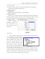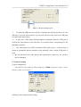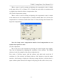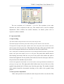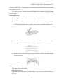
1
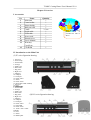
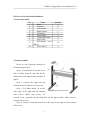
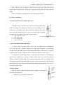
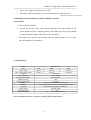
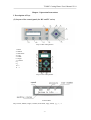
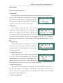
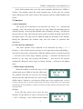
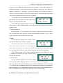
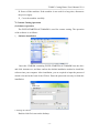
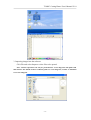
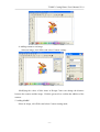
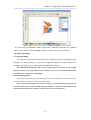
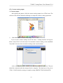
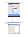
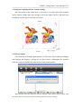
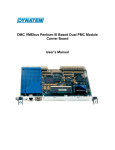
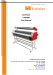
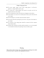
TC&DC Cutting Plotter User's Manual-V1.0 Chapter 1 Important Notes The power supply voltage of the TC/DC cutting plotter is AC220±10%; otherwise, a voltage stabilizer must be used. The carriage has a strong magnetic field, please do not place any fine iron magnetic objects near the carriage. Prevent foreign objects such as pins and screws dropping into the machine. If the machine is not used for an extended period of time, please disconnect the power supply. Do not hot-plug in or out cables connected with the computer. Prevent the punch roller pressing the grit roller for a long time if the machine is not working. The enclosure of the cutting plotter should be connected with the computer chassis and grounded. Sufficient space should be provided around the machine so as to prevent graphic or text distortion caused by the impacting on objects around by paper. Warning This is a Class A device. It may cause radio interference in a living area, in which case the user may be requested to take appropriate measures. -1- TC&DC Cutting Plotter User's Manual-V1.0 Chapter 2 Overview I. Accessories No. 1 2 3 4 5 6 7 8 9 10 11 Name Main unit Cutter holder Plotter holder Ball-pen refill Cutter Serial cable USB cable Power cord Shroud cover User's Manual Warranty 12 Certificate CD-ROM Quantity 1 1 1 1 3 / box 1 1 1 1 1 1 1 II. Introduction to the Main Unit (I) TC series figuration drawing 1. Left cover 2. Cutter clamp 3. Cutter holder 4. Carriage 5. Guide cover 6. Pinch roller 7. Key panel 8. Right cover 9. USB port 10. USB port 11. Serial port 12. Power socket 13. Sensor 14. Power switch 15. Pinch roller holder assembly 1. Left cover 16. LCD 2. Cutter clamp 17. Rubber pillar 3. Cutter holder 4. Carriage 5. Guide cover 6. Pinch roller 7. Key panel (II) DC series figuration drawing 8. Right cover 9. USB port 10. USB port 11. Serial port 12. Power socket 13. Fuse holder 14. Power switch 15. Pinch roller holder assembly -216. LCD 17. Sensor 18. Rubber pillar Note: Special cutting plotter stand is provided for 800 or above. TC&DC Cutting Plotter User's Manual-V1.0 III. Parts of the Stand and Installation 1. Parts of the Stand No. 1 2 3 4 5 6 7 8 9 10 Name Pillar Pillar bar Left column Right column Crossbeam Paper holder Connection board Paper roller Self-tapping screw M4×20 Screw M4×8 Quantity 4 2 1 1 1 2 2 1 12 8 2. Stand Assembly Please see the figuration drawing of the stand shown below: Step 1: Thread Pillar ① into the screw hole on Pillar beam ② and then fix the pillar beam to the right and left columns ③ and ④. Step 2: Connect the right and left columns with Crossbeam ⑤ with screws. Step 3: Fix Paper holder ⑥ on the inner sides of the right and left columns Figuration drawing of the stand with screws. Make sure screws are securely fixed, especially the threaded hole on the paper holder, which must be secured with a screw. Step 4: Connect Connection board ⑦ to the tops of the right and left columns with screws. -3- TC&DC Cutting Plotter User's Manual-V1.0 Step 5: Remove the 4 pillars of the main unit, place the main unit on the connection board and then connect the connection board and main unit with the pillars. Step 6: Install Paper roller ⑧ on the roller on the paper holder. IV. Cutter and Plotter 1. Structure of the Cutter Holder and Parts A standard cutter can rotate in the precision bearing on the cutter holder. A spring pocket clamps the cutter to prevent it falling off. The shell of the cutter holder can rotate to adjust the length of the cutter out of the cutter holder shell so as not to cut off the paper. Pressing the cutter bar can push the cutter out for replacement. 1. 2. 3. 4. Cutter (diameter is 2mm) Cutter holder shell Cutter holder body Cutter-exiting staff Structural diagram of the cutter holder 2. Cutter Installation and Adjustment A. Please clean the cutter holder, cutter and your hands before installing the cutter. Fine dust in a precision bearing may affect the sensitivity of the bearing. Carefully insert the cutter into the cutter holder and then use soft plastic or a eraser to push the cutter into place. Take care not to damage the blade tip of the cutter. B. Rotate the cutter holder shell to stretch the cutter blade out. Generally, the cutter blade stretched out is about 0.25mm (longer when it is used for imported reflective film). The cutter blade can be stretched out longer when it is used for a long time and becomes blunt (preferentially replace it). Proper adjustment of the stretched out length of the cutter blade can provide better output and prolong the service life of the cutter and the batten. 3. Plotter Holder With the plotter holder provided with the machine, even cheap ball-pen refills can be used for plotting. 1. Remove the cap of the pen manually. -4- TC&DC Cutting Plotter User's Manual-V1.0 2. Sleeve the compressed spring on the refill. 3. Thread the refill through the pen cap and fasten the cap and the sleeve. Structural diagram of the plotter holder 4. Installing the Cutter Holder (or Plotter Holder) onto the Cutter Stand 1. Power off the machine. 2. Loosen the screws of the cutter stand, and place the cutter holder or the plotter holder into the V-shaped position. The blade tip or the pen tip should contact the plastic batten. Fasten the screws clockwise. 3. The blade tip or pen tip can be lifted from the plastic batten for 2 to 3 mm after the machine is powered on. V. Specifications Model Spec Max. width Max. paper feeding width Speed Cutter pressure Mechanical resolution Buffer memory Repeated precision Motor Interface Language Power supply Working temp. Working humidity TC\DC series 801 1261 800 mm 1260 mm 880 mm 1340 mm 500 mm/s (30—500)g 0.025mm/step 1Gb 0.125mm Step motor constant current driving 1. Compatible with RS—232 2. Compatible with USB Compatible with DM/PL and HP/GL AC220V, 50Hz 0 ~ 35℃ 5% ~ 95% (no condensation) 631 630mm 710mm Note: Technical parameters are subject to change without further notice. -5- TC&DC Cutting Plotter User's Manual-V1.0 Chapter 3 Operation Instructions I. Description of Keys (I) Layout of the control panel (for DC and TC series) Keys of DC cutter/plotters 1. Reset 2. Offline 3. Self-check 4. Copy 5. Udisk 6. Origin 7. Confirm 8. ↑ 9. ↓ 10. ← 11. → Keys of TC cutter/plotters LCD module Keys: Reset, Offline, Origin, Confirm, Self-check, Copy, Udisk, ↑, ↓, ←, →. -6- TC&DC Cutting Plotter User's Manual-V1.0 (II) Functions 1. States of the cutter/plotter a. Reset state The cutter/plotter enters the reset state when it is powered on or the Reset key is pressed. The carriage moves rightward until it reaches the right limit switch. After the carriage stops, the grit roller rotates forward and backward. The reset process is complete. The LCD is as shown on the right Reset state b. Idle state The machine enters the idle state after it completes resetting or plotting. In the idle state, the machine is waiting for the data input of the PC and user operations. The LCD displaying in the idle state Idle state is as shown on the right. 600 indicates that the speed is at the 6th level, 30 indicates that the pressure of the cutter is at the 30th level and 0 indicates that number of copies is 0. c. Plotting state The machine enters the plotting state when the Self-check key is pressed or the PC assigns the plotting data to it. The LCD display is as shown on the Plotting state right during plotting. d. Offline/Manual state When the Offline key is pressed during plotting or in the idle state, the machine will enter the offline/manual state. In this state, the machine stops plotting and you can move the carriage and the grit roller with the direction keys. The LCD is as shown on the right Offline/Manual state e. Data receiving state When the PC is sending data to the machine, it enters the data receiving state. In this state, the machine receives data sent by the PC and all keys except Reset are invalid. After the receiving is complete, the machine exits from the data receiving state and enters the plotting state. f. Origin returning state -7- TC&DC Cutting Plotter User's Manual-V1.0 In the offline/manual state, move the motor manually and then press Offline or Confirm. The machine enters the origin returning state. In this state, the carriage motor and the grit roller motor return to the positions under the Offline/Manual state in turn. 2. Functions a. Speed adjustment The speed can be adjusted in two directions by using ↑ or ↓. Pressing and releasing ↑ once will increase the speed by one stage. When the maximum speed is reached, pressing ↑ will reach the minimum speed; similarly, pressing ↓ will decrease the speed by one stage, and when the lowest speed is reached, pressing it will turn to the highest speed. The speed can be adjusted during the operation of the machine. During the adjustment, the machine stops and will resume its operation after adjustment. b. Cutter pressure adjustment The cutter pressure can be adjusted in two directions by using ← or →. Pressing → once will increase the pressure by one stage and pressing and holding → can increase the pressure continuously. When the highest pressure is reached, pressing → will turn to the lowest stage; similarly, pressing ← each time will decrease the pressure by one stage and pressing and holding ← will decrease the pressure continuously. When the lowest stage is reached, pressing ← will turn to the highest stage. c. Offline/Origin repositioning When the machine is in the idle state or in the working state, press Offline to enter the offline state. The machine stops and you can move the carriage and the grit roller with direction keys. Press Origin, Offline and/or Confirm to exit from the offline state to the original state. After the carriage or the grit roller is moved, pressing Origin will set the current point as the origin (origin repositioning). Pressing Offline or Confirm will enter the origin returning state and return to the original position. d. Copy In the idle state, press Copy to enter the copy interface. Set the number of copies (at most 99) with ← and →. Pressing → once will increase the number -8- TC&DC Cutting Plotter User's Manual-V1.0 of copies by one. When the number reaches 99, pressing → will set the number to 1; similarly, pressing ← once will decrease the number of copies by one. When the number is reduced to 1, pressing ← will set the number to 99. When the number of copies is set, press Confirm. If data exists in the memory of the machine, the machine will plot the patterns saved in the memory repeatedly. If no data exists, the machine will refuse to plot and the screen is shown as on the right. Press any key to return to the idle state. Note: When the copying function is used, if the data is from a Udisk, the disk cannot be removed from the port, otherwise, the function cannot be used. e. Trial (self-check) In the idle state, press Self-check. The machine outputs the self-check graphic. You can check the cutter pressure and the speed through self-check so as to find a proper cutter pressure and speed for your work. f. Udisk If your machine supports the U-disks, it can directly load data from U-disks for plotting. Press Udisk. The machine will search the USB port to check if any U-disk is connected; if yes, it will display the names of files under the directory of the U-disk. You can search the file to be plotted with ↑ or ↓ and then press Confirm to load the data from the selected file for plotting. If no U-disk is found or the U-disk is damaged when you press Udisk, the it will be displayed as shown on the right. Press any key to return to the idle state. g. Contour cutting If your machine supports the contour cutting, you can cut a graphic along the contour. For details, see Contour cutting operation. Note: The contour cutting is demanding for users and the machine. We cannot ensure that every machine has the completely same precision. Each user has his/her level of familiarity with the machine, so we cannot ensure the quality of the contour cutting by different users. It is recommended to keep a 2mm space between the contour and the image. II. USB Driver Installation and Operation Instructions -9- TC&DC Cutting Plotter User's Manual-V1.0 (I) System requirements: PC: Intel815 or above, PIII 1G CPU; Intel CPU and chipsets are recommended; Operating system: Windows2000/XP or later. (II) Installation and operation 1. Install the driver Run SETUP.EX and click INSTALL for pre-installation. 2. Install the hardware When a device is connected to the PC through USB port, the system will prompt "Found New Hardware Wizard". Click Next until the installation is complete. A USB icon will be displayed at the lower right corner of your PC after installation. 3. Configure the port After hardware installation, configure the new COM port in the device manager as shown in Figure (1): Figure (1) Port configuration (III) Precautions 1、 When a USB port is used, please select a port consistent with that displayed in the device manager (for example, COM3); 2、 When plotting software (for example, Wentai, CutterMaster, flexi, sugncut, etc) is used, make sure the output port of the software is consistent with that of the device manager, as shown in Figure (2). Please note the port number added in the device manager. If the port number is not Figure (2) Ports consistent, please make them consistent, as shown in Figure (3), and then restart your computer; otherwise, connection failure may occur when the USB port is used for output (if the COM3 port is used by another device, remove the device and then reconnect the device after the cutter/plotter has used the port). - 10 - TC&DC Cutting Plotter User's Manual-V1.0 Figure (3) Advanced settings for ports 3、 For different USB ports are used, the COM ports provided by the driver are also different; to prevent inconvenience to your work, please use the same rear USB ports to connect the cutter/plotter. 4、 It may take a little longer during hardware installation when the USB port is used by the cutter/plotter for the first time. It is normal. Please wait patiently for the installation interface. 5、 The cutter/plotter uses USB 2.0 and the USB cable used is 1.5 meters long. It cannot be guaranteed that the machine works normally when a longer USB cable is used. 6、Do not disconnect the cable during data transmission; otherwise, the interface may be damaged. III. Software Setting (I) Port configuration The baud rate of the COM port and the USB port is 57600 or 56K; flow control: 1 and 3; data bit: 8; check: None; stop bit: 1. Port configuration (II) Sharp corner compensation setting - 11 - TC&DC Cutting Plotter User's Manual-V1.0 When a cutter is used for cutting and plotting, the compensation value is related to the cutter offset: 0.25→0.28mm, 0.25→0.56mm; the cutter offset is consistent with or slightly larger than the software compensation value. (III) Closed compensation setting When a cutter is used for cutting and plotting, the compensation value is related to the character size: the compensation to a character smaller than 1cm is 0.1mm, the compensation to a character smaller than 10cm is 0.3mm, the larger the character the larger the compensation. Compensation setting Note: the sharp corner compensation and the closed compensation are not needed when a plotter is used. (IV) Size adjustment Due to the error in the mechanical processing, the actual length varies slightly. This can be eliminated by adjusting the resolution of the software. The Wentai software is used for example to show how to adjust the size. First, make a 50*50cm square with the software and check and record the X resolution a1 of the software (in Wentai software, click Options to open the output interface; click Setting to display the following setting interface), and then draw a square with the plotter. Measure the length L along the grit roller with a ruler (in cm). - 12 - TC&DC Cutting Plotter User's Manual-V1.0 Size adjustment The new resolution in X direction = L×a1÷50. The resolution in the other direction can also be adjusted in this way. This method can be used for multiple adjustments. Other software has similar functions, for details, please refer to respective software manuals. IV. Operation Skills 1. Paper loading ① Lift the handle of the pinch roller to lift it away from the grit roller. ② Thread the paper between the pinch roller and the grit roller from the end to the head. ③ Align the front edge of the paper with the seam of the front panel of the machine and lower down the right side of the pinch roller. Then align the left edge of the paper with the mark line of the front panel and then lower down the left side of the pinch roller. Note: Cutter/plotters of different specifications are provided with different numbers of pinch roller holders. Each pinch roller holder can move on the guide. The pinch roller handle must be lifted during movement. Hold the rear part of the pinch roller holder and push it leftward and rightward. Do not pull the pinch roller bar from the front part; otherwise, the precision of the machine may be caused. Caution: The right pinch roller holders can be moved, but it must be guaranteed that all holders are pressing on the grit roller. The right pinch roller holders must be out of the area of the graphic being plotted and 10-50mm away from the paper edge. The number of pinch roller holders should be determined according to the width of the graphic being plotted. 2. Cutter pressure adjustment If the cutter pressure is too small, the cutter may not be able to cut into the film, - 13 - TC&DC Cutting Plotter User's Manual-V1.0 causing cutting failure; if the pressure is too large, the deformation may be caused and paper may be cut off. The cutter pressure and the cutter blade length can be adjusted through plotting the test image. 3. Lift up/Overlay After plotting A、Cut the plotted part with scissors or a utility knife. B、Place it on the table and tear off needless parts with tweezers (to facilitate tearing off the needless parts, a frame can be made around the plotted parts). C、Coat the overlay film on the cut pattern and flatten it securely (with a scraper). D、Remove the overlay film from the base and paste it where needed and then remove the film. 4. After the work A. Lift the pinch roller handle. B. Unload the paper. C. Remove the cutter holder or plotter holder, wipe with soft cloth and keep it carefully. - 14 - TC&DC Cutting Plotter User's Manual-V1.0 D. Power off the machine. If the machine is not used for a long time, disconnect the power supply. E、Cover the machine carefully. V. Contour Cutting Operation (I) Software operation The FLEXI-STARTER-AUTOMARK is used for contour cutting. The operation of the software is as follows: 1、 Software installation Insert the CD-ROM containing FLEXI-STARTER-AUTOMARK into the drive and click Autorun.exe, and then confirm the default installation method to install the software into your computer. After installation, you are required to input the password which is located at the back of the CD box. Enter the password correctly to finish the installation. 2. Starting the software Double-click flexi-start on the desktop. - 15 - TC&DC Cutting Plotter User's Manual-V1.0 3. Importing images into the software Click File and select Import to select files to be opened. Note: Contour operations can only be performed for vector diagrams with paths with this software. For details on how to add the path to a vector diagram, see How to Add Path to a Vector Diagram. - 16 - TC&DC Cutting Plotter User's Manual-V1.0 4. Adding contour to an image Select an image, click Effect and select Contour cutting; Modifying the values of blue items in Design Center can change the distance between the contour and the image. Click the green tick to confirm the addition of the contour. 5. Adding MARK Select an image, click Effect and select Contour cutting mark; - 17 - TC&DC Cutting Plotter User's Manual-V1.0 If you are using an automatic model, please select Automatic marking. For a manual model, please select 4-point marking and then click the green tick to confirm. (II) Pattern printing 1. Pattern printing The Flexi-start supports direct printing from a printer, but does not support spray printing. For spray printing, you need to output the pattern in other formats (for example, eps, bmp, jpg, etc.) and print it through other software. Note: Resolution insufficiency may occur in output patterns. You can use the original pattern to overlay it by using software, but remember not to overlay the mark and keep the size and position of the pattern unchanged. 2. Placing the pattern After printing the pattern, place the printed pattern on the cutter/plotter. For details about how to place the pattern, see Paper loading in Operation Skills. Note: To ensure the quality of the contour cutting, try to place the pattern properly; the direction of the pattern on the machine should be consistent with that in the computer (the bottom of the pattern in the computer is the front part of the cutter/plotter). - 18 - TC&DC Cutting Plotter User's Manual-V1.0 Displayed in the computer Pattern placement (III) Sensor compensation setting The cutter/plotter needs to find the four marks around the printed pattern before contour cutting. The sensor and the plotting position (the position where the cutter or refill tip contacts with the material after the cutter holder or plotter holder is clamped) are not on the same point. To ensure that the positions of the marks found by the sensor are consistent with the plotting position, the sensor needs to be moved to the position for normal plotting and then starts to find marks. The distance moved is the sensor compensation value. The compensation value of a machine is slightly different from that of others and needs to be set by users. The setting is divided into two parts: initial setting and tuning. The tuning will be discussed later. The initial setting is as follows: Mount the plotter holder on the carriage, power on the machine (or press Reset) and press and hold the right direction key. Release the right key. The LCD displays as shown. Move the refill tip to the mark 1 (if the key operation is inconvenient, you can also lift the pinch roller to move the material manually. Be sure the pattern is properly placed after moving and the pinch roller is lowered down). Press Origin. The machine starts the sensor to automatically search the mark 1 and record the offset value detected. - 19 - TC&DC Cutting Plotter User's Manual-V1.0 (IV) Contour cutting output 1. Contour output After placing the pattern, click the contour cutting output icon of Flexi-start. The software will start the Production Manager to output the contour cutting operations. 2、 PROODUCTION MANAGER setting If you use the contour cutting for the first time, a setting interface will appear. Please select LiYu Cut for the cutter. For automatic contour cutting, select AutoMark Test-AMU. You can select a model according to the actual machine. After selecting the model, click Next to set the port and the baud rate. The port should be consistent with that assigned by the computer. The baud rate of the port is 57600. Click Finish after setting to complete setting PRODUCTION MANAGER. - 20 - TC&DC Cutting Plotter User's Manual-V1.0 After the PRODUCTION MANAGER is correctly set, the Flexi-start displays a pattern output interface. - 21 - TC&DC Cutting Plotter User's Manual-V1.0 3. Setting the original point for contour cutting After the setting of the output device, you need to re-set the origin of the machine before contour cutting. Move the carriage to the lower right of Point 1 and make sure the pattern is at the upper left of the new origin. 4. Software output Click Send on the cutting output interface of Flexi-start. The Production Manager will respond and displays a dialog box as shown below. Meanwhile, the machine starts the sensor to find the four mark points of the printed pattern. When the four points are found, the sensor is stopped. Click Confirm. The computer sends the contour data to the machine and the machine performs the contour cutting. - 22 - TC&DC Cutting Plotter User's Manual-V1.0 (V) Sensor tuning After initial setting, the contour may not be good enough and offset may occur. You can tune the sensor to correct the offset. The method is as follows: Draw a 10-10cm square in Flexi-start and add automatic contour marks. The distance between the contour and the square is 0. Use the plotter for the contour cutting output as you usually do. Pattern displayed on the computer Actual contour pattern Normally, the contour integrates with the pattern closely. Poor integration is caused by the error of the compensation value of the sensor. If the error can be adjusted manually, press Origin in the idle state and then immediately press Udisk and hold it until the LCD shows the pattern as shown on the right. Move the contour with direction keys to fine adjust the errors in two directions. Press the down key if the contour is on the upper part and press the left key if the contour is on the right (as shown, move leftward and downward to adjust). Moving a unit will move the contour 0.025mm. After adjustment, press Confirm to complete the tuning and the machine returns to the idle state. This method can be used repeatedly to adjust the prevision of the contour cutting. - 23 - TC&DC Cutting Plotter User's Manual-V1.0 Chapter 4 FAQ I. I cannot enter the plotting environment, what can I do? 1. The system files are corrupted. Re-install the system with the CD-ROM. 2. Check whether the software works normally. You can press Alt+Tab to among different interfaces to check. II. Plotting output is invalid. What can I Do? 1. Check whether the dongle of the software is correctly installed (please refer to the software manual). 2. If the installation is correct, but the plotting output is still invalid, please contact your dealer or the software vendor. III. The cutter/plotter does not respond during output, what can I do? 1. Check the connection between the cutter/plotter and the computer. 2. Check whether the port is correctly configured. The port configuration in the software output menu should be consistent with the serial and parallel ports connected the computer and the cutter/plotter. 3. Check whether a correct model is selected for output. 4. Check whether the machine is online. 5. Check whether the software is damaged, if yes, re-install the software. 6. The output port of the computer is damaged. 7. If this is encountered when CutterMaster V6.2.0 is used for serial output, press Ctr+Alt+Del to close the Not respond item. For details, please refer to the CutterMaster manual. IV. What should I pay attention to for small characters? 1. For characters smaller than 2cm, set the speed of the machine to the lowest, because the gap between characters is small. if the speed is too high, the blade may tear off strokes, causing defects. 2. For small characters, ut is recommended to use the compensation function. The sharp corner compensation value should be decided according to actual situations, - 24 - TC&DC Cutting Plotter User's Manual-V1.0 usually 0.3mm to 0.5mm. In this way, better effects may be achieved. 3. The length stretched out of the blade should be shorter than that under normal conditions. In this case, the characters will be smoother. V. What should I pay attention to for big characters? 1. For characters that exceed the width of the machine, the system software will cut the characters automatically. You may also cut them manually so that you can combine different pages together to form the big characters. Please note that the output width should be the same as the width of the paster. 2. For big characters, the speed can be faster. In addition, the sharp corner compensation should be disabled during output and the seamless joint should be selected. VI. The paster cannot be removed, what can I do? 1. Adjust the stretching-out length of the blade. 2. Adjust the the stretching-out length of the blade and cutter pressure properly. Perform test cutting until satisfactory results are achieved. 3. If broken lines occur, the cutter is worn due to long-time use. Push the cutter out and replace it with a new one. As an emergency way, you can use a small piece of leather to polish the cutter. 4. If one side can be removed while the other cannot, it may be caused by improper length of the blade, the batten is not flat or is damaged. VII. What should I pay attention to for super wide (1-5m) characters? For a super wide pattern, perform tests in the offline state first. Recommendation: if segmentation is allowed, it is better to segment for plotting. 1、 Align the side edges with the scale on the machine and lower down the pinch roller holder. 2、 In the offline state, press ↓ to move the machine with the paper for a distance equal to the width of the pattern. 3、 Press Offline to return the paper to the original position. Then you can start the - 25 - TC&DC Cutting Plotter User's Manual-V1.0 actual plotting. VIII. Why could deflection occur? 1. The pinch roller is improperly used. 2. The pinch roller is severely worn. 3. The paper is improperly aligned. 4. No test is performed for a super wide pattern. IX. Non-fault issues 1. The offline indicator lamp (yellow) and the setting indicator lamp (green) light up alternately or at the same time every second. The machine stops plotting. It indicates the data transmission is in progress, please wait. 2. The setting indicator lamp (green) lights up every second or the speed indicator lamp lights up periodically. It indicates that the copying operation is invalid. Pressing any key for two seconds can resume the normal state. 3. The machine cannot be reset immediately after being powered on. Press Reset to solve the problem. - 26 -