1
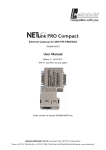
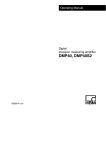
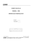
USH-8
Ultrasonic Snow Depth Sensor
Document release: V01.00
Software release: V01.58
Stand: September 2008
User Manual
Sommer Mess-Systemtechnik
Sommer GmbH & Co. KG
Straßenhäuser 27, A-6842 Koblach, Österreich
Tel +43 5523 55 989 Fax +43 5523 55989 19
www.sommer.at
[email protected]
Table of contents
1. GENERAL DESCIPTION .................................................................................................................... 1
1.1. MEASUREMENT CYCLE ..................................................................................................................... 1
1.2. MEASURING PRINCIPLE AND ACCURACY ............................................................................................ 1
1.3. SIGNAL PROCESSING AND FILTERING OF INTERFERING SIGNALS.......................................................... 2
1.4. LOW ENERGY CONSUMPTION ............................................................................................................ 2
2. HARDWARE........................................................................................................................................ 3
2.1. SCOPE OF DELIVERY ........................................................................................................................ 3
2.1.1. Sensor .................................................................................................................................... 3
2.1.2. Connector............................................................................................................................... 3
2.1.3. Documents ............................................................................................................................. 3
3. INSTALLATION ................................................................................................................................... 4
3.1. QUALIFICATION OF THE MEASUREMENT SITE...................................................................................... 4
3.1.1. Qualification of the area ......................................................................................................... 4
3.1.2. Preparation of the measurement site ..................................................................................... 4
3.1.3. Assembling and height of mounting ....................................................................................... 4
3.1.4. Cable ...................................................................................................................................... 5
3.1.5. Power supply / consumption .................................................................................................. 5
3.1.6. Interface ................................................................................................................................. 5
4. QUICK USER GUIDE.......................................................................................................................... 7
4.1. OVERVIEW ...................................................................................................................................... 7
4.2. MOUNTING HEIGHT .......................................................................................................................... 7
4.3. POWER SUPPLY ............................................................................................................................... 7
4.4. CONNECTING FOR PARAMETERIZATION ............................................................................................. 8
4.5. PARAMETERIZATION MENU ............................................................................................................... 8
4.6. OUTPUT MEASUREMENT VALUE ........................................................................................................ 9
4.7. DEFAULT VALUES ............................................................................................................................ 9
4.8. SETTING-UP OPERATION ................................................................................................................ 10
4.9. CHECK MEASUREMENT .................................................................................................................. 10
5. PARAMETERIZATION ...................................................................................................................... 11
5.1. LINK CONNECTION ......................................................................................................................... 11
5.2. MENU - USER INTERFACE HYPERTERMINAL ...................................................................................... 11
6. PROTOCOLS FOR DIGITAL INTERFACE....................................................................................... 13
6.1. OUTPUT TYPE / OUTPUT FORMAT OF MEASURED VALUES ................................................................. 13
6.1.1. Standard protocol ................................................................................................................. 13
6.1.2. Protocol 1 ............................................................................................................................. 13
6.1.3. Protocol 2 ............................................................................................................................. 13
6.1.4. Spectrum .............................................................................................................................. 14
6.2. CHECKSUMS ................................................................................................................................. 14
6.2.1. Protocol 1 checksum ............................................................................................................ 14
6.2.2. Protocol 2 checksum ............................................................................................................ 14
6.3. POLLING MODE .............................................................................................................................. 14
6.3.1. Switch polling mode on/off ................................................................................................... 14
6.3.2. Poll command....................................................................................................................... 15
7. PARAMETERIZATION ...................................................................................................................... 16
7.1. MAIN MENU ................................................................................................................................... 16
7.1.1. Menu item 1: Measuring interval .......................................................................................... 16
7.1.2. Menu item 2: Distance/Level................................................................................................ 16
7.1.3. Menu item 3: Zero point (mm).............................................................................................. 16
7.1.4. Menu item 3: S-range blanking (mm)................................................................................... 16
7.1.5. Menu item 4: L-range blanking (mm) ................................................................................... 17
7.1.6. Menu item 6: Filter ............................................................................................................... 17
7.1.7. Menu item 7: Increasing damping ........................................................................................ 17
7.1.8. Menu item 2: Decreasing damping ...................................................................................... 17
7.1.9. Menu item 9: Average value ................................................................................................ 17
7.1.10. Menu item A: Output type .................................................................................................. 18
7.1.11. Menu item B: Handshake (Trigger-Pin) ............................................................................. 18
7.1.12. Menu item C: Protocol menu.............................................................................................. 18
7.1.13. Menu item D: End range 20mA (mm) ................................................................................ 19
7.1.14. Menu item E: Serial configuration ...................................................................................... 19
7.1.15. Menu item F: Simulation current ........................................................................................ 20
7.1.16. Menu item G: Info............................................................................................................... 20
7.1.17. Menu item H: Lang./Sprache ............................................................................................. 20
7.1.18. Menu item X: Exit ............................................................................................................... 20
8. USH-8 TECHNICAL SPECIFICATIONS ........................................................................................... 21
9. FAQ ................................................................................................................................................... 22
9.1. NO VALUES ................................................................................................................................... 22
9.2. MEASURES ALWAYS THE SAME MEASUREMENT VALUES ................................................................... 22
9.3. INACCURACY MEASUREMENT VALUES ............................................................................................. 22
9.3.1. Fence around measurement site ......................................................................................... 23
9.4. SENSOR OUTPUTS FALSE MEASUREMENT VALUES ........................................................................... 23
9.5. MEASUREMENT IN A ROOM FOR E.G. TESTING.................................................................................. 24
10. ROHS – DECLARATION OF CONFORMITY ................................................................................. 25
11. CE – DECLARATION OF CONFORMITY....................................................................................... 26
1. General Desciption
The USH-8 sensor measures the snow depth by ultrasonic.
Feature of USH-8:
• Continous and non-contact ultrasonic
snow depth measurement
• Reliable sensor for extreme
conditions
o Accurate measurement during
snow fall and difficult reflexion by
snow surface
o Automatic de-icing of ultrasonic
membrane
• High accuracy of measurement
o Integrated temperature
compensation
o Intelligent measurement
processing
• Low energy consumption
o Standby
o Optimal for solar powered supply
• Easy sensor integration
o Analoge and digital interface
o Parameterization via
Hyperterminal
Fig. 1: USH-8 sensor
1.1. Measurement cycle
The sensor wake up from Stand-by mode and send a sequence of ultrasonic impulses and receive the
reflected impules. That followed the sensor processes the reflected impulses (damping, filter) and
send the measured value to the analog and/or digital interface. Now the sensor goes to Stand-by
mode again and wakes up for the next measurement cycle.
1.2. Measuring principle and Accuracy
The measuring principle based at the runtime measurement of an ultrasonic impuls. The sensor send
per measurement several high energy impules to the snow surface and receive the reflected impulses.
On the basis of runtime the sensor is calculating the current snow depth.
The air temperature has an important influence to the runtime of the ultrasonic impuls. Therfore the
sensor has an integrated temperature compensation. The current air temperature is included in the
calaculation of the snow depth.
The calculation of the snow depth is done by the sensor, so the data signal is the corrected snow
depth with an accuracy of 0,1% FS.
Fig. 2: Signal processing USH-8
1.3. Signal processing and filtering of interfering signals
The USH-8 sensor is designed for extreme weather conditions to enable a reliable measurement. The
high energy 50kHz ultrasonic impulses measures reliable under difficult snow surface like fresh-fallen
snow or powder snow. Furthermore the high energy impulses prevent a icing of the ultrasonic
membrane. The intelligent signal processing filters snow fall and precipitation to enable a reliable
measurement of snow depth. Also the influence of cars are filtered when a snow depth measurement
is done at roads.
1.4. Low energy consumption
The sensor has an intelligent signal processing and switch autonomous between Stand-by and
measurement phase.
Attention:
The data logger may not switch on/off the USH-8 sensor. The sensor should
supply all the time by 12VDC. Then a very low energy consumption with best
measurement result can be achieved.
There are two different output mode of the analogue and/or digital interface. The last measured value
can be output continuous on the analogue/digital interface or the interface can be
activated/deactivated by a trigger-pin to save power consumption. For a measurement interval of 1
minute the sensor consume 0.5 Ah per day. The sensor is powered by an operating voltage of 11 to
15 V DC.
2. Hardware
2.1. Scope of delivery
2.1.1. Sensor
The sensor has already been calibrated (temperature compensation) and preconfigured prior to
delivery. In addition to the customer-specific settings (interface, protocol, …), the zero point parameter
for the location must be set after the installation. This is implemented easily and comfortably via the
Windows Hyperterminal.
2.1.2. Connector
The sensor is connected by an 12-pin connector. The connector is included in the scope of delivery
but not the cable.
Fig. 4: Connector pin
assignment, male
Fig. 3: Plug connection
[*]
Pin
A
B
C
Cable
Brown
Green
Yellow
Name
+12V (11V-15V DC)
Impulse output
Trigger / Handshake
D
E
F
G
H
J
K
White
Pink
Red
Blue
Grey
Violet
Grey/pink
GND
RX
TX
RTS
PSEN
Analogue output: 4 -20 mA
Temp-
L
Blue/red
Temp+
M
Black
GND
* Cable color when use of „Sommer“-Kabel
** Not available in the basic version of the sensor
Fig. 5: Connector pin
assignment, female
Description
Supply voltage
Pin to activate/deactivate analog
interface
Ground for power supply and signal
Receive Data
Transmit Data
Request to Send
Pin to program the sensor
Analogue output 4 - 20 mA
Connection for external temperature
[**]
sensor
Connection for external temperature
[**]
sensor
Ground for power supply and signal
2.1.3. Documents
Following documents are included
• Manual incl. CE- Declaration of Conformity and RoHs- Declaration of Conformity.
3. Installation
3.1. Qualification of the measurement site
Because of environmental influence like weather pattern and terrain is the selection of the
measurement site essential if the measurement should be representative for a region.
3.1.1. Qualification of the area
The terrain of the measurement site should show following characteristics: flat area, sheltered from the
wind and safe from avalanches. Steep slopes, troughs, edge or boulders should be prevented next to
the measurement site. Ideally the measurement site is a large and blank area with a representative
snow cover for the region.
A terrain edge next to the ultrasonic measurement filed has a negative impact to the measurement
result. Also snow drift is produced by an edge, building, houses, trees or fences next to the
measurement site. Is the measurement site in a slope the snow cover can slip. For an optimal
measurement the sensor is parallel to the soil / snow cover.
3.1.2. Preparation of the measurement site
The material of the field of measurement’s surface must be representative of the area to be examined,
since differing materials produce differing defrosting capacities, and may thereby lead to undesired
disruptions of the field of measurement. For measurement in natural terrain, we recommend fine
gravel or crushed rock for the preparation of the field of measurement’s surface.
The diameter and minimum distance of the measurement spot to the mast have to be considered
when the planning of the measurement site starts. These considerations should prevent unintentional
reflexions of the ultrasonic signal.
If the measurement site should protect by a fence an adequate separation distance between fence
and measurement spot of the sensor should be taken into account. Any barrier next to the
measurement site can produce snowdrift which falsified the measurement of the snow depth.
3.1.3. Assembling and height of mounting
The optimal mounting height of the sensor is 3m or more. The maximum permissible mounting height
is 10m. Care must be taken here that the diameter of the field of measurement in this case is greater
than 3m. In order that the field of measurement is not disrupted, two distances must be kept in mind
when setting up the station. Firstly, there is the distance between the sensor and the field of
measurement, and secondly, there is the distance between the sensor and pole / pole base. When the
field of measurement is disrupted, this can lead to undesired reflections, and therefore to incorrectly
measured data. Objects in the vicinity of the field of measurement (i.e. terrain edges, buildings, ...)
also create snow drifts, thereby causing undesired disruptions of the field of measurement.
H (m)
Ø (m)
DB (m)
2
0,6
1,0
3
1,0
1,2
4
1,3
1,4
5
1,6
1,6
6
1,9
1,8
7
2,2
2,0
8
2,5
2,2
Tab. 1: Diameter measuring field,
sensor heigth, distance measuring
field - base
Fig. 6: Assembling
3.1.4. Cable
Recommendation
Attention:
Tip:
Screened data cable LIYCY 12 x 0,25 mm²
Take into account the voltage drop when you use a long cable. The voltage at
the sensor must be at least 10.5 VDC. The recommended cable should use
for a maximal length of 10m.
It make sense to use a 12pin data cable to integrate the serial interface in one
cable. Then the serial interface is also routed into the electrical cabinet. In
case of maintenance a notebook can easily connected to the serial interface
of the USH-8 and start the hyperterminal for parameterization.
3.1.5. Power supply / consumption
Requirement:
Supply voltage: 10.5 to 15 VDC
Current demand: max. 200 mA during measurement period
(measurement period about 3 seconds);
< 1 mA (Standby-Mode)
Power consumption: 0,5 Ah / day (measurement interval 1min)
Attention:
The sensor need a minimum supply voltage of 10.5 VDC, if the voltage is
below 10.5 VDC the measurement can be inaccurate.
3.1.6. Interface
Analogue:
Output: Snow depth
0/4 - 20 mA (configurable)
Resolution: 12 Bit
Max. burden: 300
Digital:
Preparation:
Output: Snow depth; air temperature; quality flag
RS 232; serial interface
Protocol: various ASCII formats
We recommend using a 12pin data cable to integrate power supply, analogue
interface (if used) and serial interface (RS232) in one cable and route this
cable into the electrical cabinet. Then prepare a connector for the serial
interface to maintain the sensor. In case of maintenance the technican can
easily connect a notebook at the prepared serial interface in the electrical
cabinet to maintain the sensor by hyperterminal.
4. Quick user guide
4.1. Overview
1. Mounting sensor at mast
Chapter 4.2
2. Connect cable to sensor and 12 VDC power supply
Chapter 4.3
3. Connect sensor with the serial interface to notebook
Chapter 4.3
4. Start hyperterminal at nootebook and connect to
sensor for parameterization
Chapter 4.4
5. Parameterization and set-up
Chapter 4.5, 4.7, 4.8
6. Function control
Chapter 4.9
4.2. Mounting height
The distance between sensor and measurement surface (e.g. surface of snow cover) has be greater
than 900mm. For minimum distance between sensor and mast / base see table 1. Consider the
maximal possible snow height of the snow cover at the measurement site!
4.3. Power supply
The supply voltage of the sensor is 10.5 to 15 VDC.
Attention:
The data logger must not switch on/off the power supply of the sensor. The sensor
works in a own measurement interval and output continuous the last measured value
or only wake up for output the value by activating the trigger pin. The sensor switches
automatically between measurement and stand-by-mode. If the data logger switches
on/off the power supply of the sensor an inaccurate measurement will occur, because
the intelligent measurement processing of the USH-8 is always reseted.
Two modes are available to transmit the measured value to the data logger
• Default (delivery): After each measurement the value is transmitted continuous by analogue
(4-20mA) / digital interface (RS232) – more information chapter 7.1.11 Menu B: Handshake
(value=0).
• If +12VDC apply to the trigger-pin the analogue/digital interface is activated and the last
measured value is transmitted - more information 7.1.11 Menu B: Handshake.
Fig. 7: Power supply and data transmission via "trigger-Pin" (Handshake)
4.4. Connecting for parameterization
To connect to the sensor a modem-connection is established between the serial interface (RS232) of
the sensor and a notebook. If the notebook doesn’t offer a serial interface we recommend to use a
“USB-serial”-adapter. After connecting the cable you start the hyperterminal at your notebook.
Example: MS Windows XP© :
Start
Programms
Accessories
Communication
Hyperterminal
Use following parameter for the setting of the COM-Port
Parameter
Value
Bits / second
9600 Baud
Data bits
8 Bits
Stopp bits
1 Stop bit
Parity
No parity
Flow control
None
Tab. 2: Default values serial interface (RS232)
The paramter of the serial interface of the USH-8 can be changed – more information chapter 7.1.14
“serial configuration”. We recommend using the default settings of the serial interface.
4.5. Parameterization menu
The connection to the sensor via hyperterminal is established. Then three "???" characters (keep the
Shift key pressed) are entered via the keyboard and the parameter setup menu (see following figure)
appears on the display. There may be a delay of up to 30 s, for instance if the sensor is actually
making a measurement. To edit a menu item, type the corresponding keyboard key (e.g. 7 for zero
point). The parameter together with the corresponding unit appears in the menu. You can then enter a
new value and store it by pressing Enter. Press ESC to quit if you do not want to modify the value.
This method can be used to set every parameter shown in the menu to the desired value. Data
entered in the menu via the keyboard is not case sensitive, i.e. upper case or lower case letters are
irrelevant.
Exit the menu by pressing "X". The sensor then makes a measurement, outputs the measured value,
changes to standby mode and makes another measurement after the selected interval has elapsed.
Fig. 8: Hypertermial - parameterization - main menu USH-8
4.6. Output measurement value
The sensor output the measurement values over the analogue and digital interface (default settings).
The output over the digital interface use the standard protocol:
4874 -01.1 [CR][LF]
Distance/level
temperatur (+/-)
CR&LF
4.7. Default values
The USH-8 sensor is delivered with following default settings:
Main menue
Serial configuration
1 Measuring interval:
10
1 Baud rate:
2 Distance/Level:
1
2 Data bits:
3 Level Zeropoint (mm):
5000
3 Stop bits:
4 S-range blanking (mm):
828
4 Parity:
5 L-range blanking(mm):
9999
5 RTS on time :
6 Filter :
1
6 HD receive window:
7 Increasing damping:
20
7 Immediately confirmation:
8 Decreasing damping:
10
X Exit
9 Average value:
0
Protocol
A Output type:
3
B Handshake:
0
1 Protocol Type:
C Protocol:
0
2 Device address:
D End range 20mA (mm):
5000
3 Station number:
E Serial config.
4 mm/cm output.:
5 Normal / Polling:
X Exit
9600
8
1
0
10
0
0
0
0
99
0
0
4.8. Setting-up operation
Default setting for measurement mode is “level
measurement“ (more info chapter 6.2.2.). To start
the measurement of snow depth the parameter
“”level zeropoint (mm)” have to be parameterized
of a sensor with default settings.
The distance “zero point” in [mm] between soil
and mounting height of the sensor has to
parameterize. After type in the distance and
quitting the main menu with “X” the sensor starts
the measurement.
If the distance should be measured the
parameter “level zero point” has no influence.
Fig. 9: Level zero point in [mm]
4.9. Check measurement
To check the sensor a test measurement is useful. If there is already a snow cover, bank up 10cm
snow to a flat area or use a piece of luggage (e.g. toolbox) to simulate an increased snow cover. A
other possibility is that a person stay under the sensor.
Attention:
After the first measurement is done and the e.g. toolbox is placed under the sensor
and the next measurement is initiated a reset of the sensor should be done (switch
power on/off). If you don´t want to switch on/off the sensor you have to set the
parameter “Increasing damping, “Decreasing damping” and “Average value” to zero
(0). We recommend to reset the modem, no reparameterization is necessary.
5. Parameterization
5.1. Link connection
To parameterize the sensor you have to setup a connection via the serial interface (RS232) between
the sensor and a notebook / PC and start the hyperterminal.
Example to start the hyperterminal with MS Windows XP© :
Start
Programms
Accessories
Communication
Hyperterminal
Use following parameter for the settings of the COM-Port
Parameter
Value
Bits / second
9600 Baud
Data bits
8 Bits
Stopp bits
1 Stop bit
Parity
No parity
Flow control
None
Tab. 3: Default values serial interface (RS232)
5.2. Menu - user interface hyperterminal
The connection to the sensor via hyperterminal is established. Then three "???" characters (keep the
Shift key pressed) are entered via the keyboard and the parameter setup menu (see following figure)
appears on the display. There may be a delay of up to 30 s, for instance if the sensor is actually
making a measurement. To edit a menu item, type the corresponding keyboard key (e.g. 7 for zero
point). The parameter together with the corresponding unit appears in the menu. You can then enter a
new value and store it by pressing Enter. Press ESC to quit if you do not want to modify the value.
This method can be used to set every parameter shown in the menu to the desired value. Data
entered in the menu via the keyboard is not case sensitive, i.e. upper case or lower case letters are
irrelevant.
Exit the menu by pressing "X". The sensor then makes a measurement, outputs the measured value,
changes to standby mode and makes another measurement after the selected interval has elapsed.
Fig. 10: Hypertermial - parameterization - main menu USH-8
6. Protocols for digital interface
6.1. Output type / Output format of measured values
The output of the measured value can transferred analog and/or digital to the datalogger. See chapter
3.2.10 for configuration of the output type. Via digital interface the measured values are output in
different formats using one of four possible protocols. Selecting a protocol is described in Section
3.2.12.
6.1.1. Standard protocol
The standard protocol is a simple easy-to-implement protocol. Measured values are output separated
by spaces.
4874 -01.1 [CR][LF]
Distance/Level
signed Temperature
CR&LF
6.1.2. Protocol 1
Measured values are output to 4 decimal places using this protocol.
I00..4874-011350148960519;
Distance/Level (snow depth in mm)
signed Temperature (in 0.1 degree)
Gain (End/Start)
Uncorrected distance
Checksum
6.1.3. Protocol 2
If this protocol is selected, the output format is as follows:
[STX]33;4874;mm;-01.1;C;4900;mm;xxx;11[CR][LF][ETX]
Start code
Device address
Distance/Level
Unit
signed Temperature
Unit
Uncorrected
distance
Unit
Status reports
Checksum
CR&LF end code
The semicolon between individual values is interpreted as a delimiter.
Protocol 2 status messages:
000
990
999
-
OK
No echo after powering up
Erroneous measurement
6.1.4. Spectrum
This type of protocoll is an enlargement of protocoll 1. After the ‘;’ from protocol 1 some echo detection
parameter are displayed and after that each individual measurement value is displayed without
correction. Measurement values are separeted through '|'.
Example:
I00..1635022730061572042F;|00|09|04|09| |06|30|1572|1569|1572|....|1572|1569|1572
6.2. Checksums
6.2.1. Protocol 1 checksum
In protocol 1, the checksum is the total of the ordinal numbers of all the characters before the
checksum (viewable in an ASCII table).
e.g.: I01..0000000000000230040B;
I is character 73, 0 is character 48, 1 is character 49, . is character 46 etc. The checksum is therefore
73+48+49+46+46+48+48+... = 1035 dec or 040B hex.
6.2.2. Protocol 2 checksum
This checksum is calculated from the total of all characters (alphanumeric characters and control
codes such as STX, ETX, CR, LF but excluding checksum bytes themselves). The two's complement
of this total is found and the low-order byte is taken from this. The high-order and low-order half byte,
converted into readable ASCII characters, form the checksum.
6.3. Polling mode
Ultrasonic sensor USH-8 can operate in automatic or polling mode. If automatic mode is set,
measured values are sent using the selected protocol after every measurement. In polling mode,
measured values are output within 10-20 ms after receiving the poll command.
The interval between signals sent to the USH-8 must not exceed 1 s, otherwise they are not accepted.
The device address can be set via the menu (see Section 3.2.12.2). The ultrasonic sensor can only be
addressed via the device address.
6.3.1. Switch polling mode on/off
Polling mode can be set to two different modes. The first mode is obtained via the menu, see Section
3.2.12.5. The second mode is obtained through commands sent via the RS232 interface. The format
of these commands is as follows:
Switch polling mode on:
Reset to automatic mode:
:DeviceaddressMP;
:DeviceaddressMA;
Example using device address 33:
:33MP;
:33MA;
Polling mode on
Automatic mode
6.3.2. Poll command
The poll command has the following format:
:Deviceaddress;
The device address must consist of two ASCII characters, e.g.: :33;
7. Parameterization
7.1. Main menu
7.1.1. Menu item 1: Measuring interval
Function:
The measuring interval is the time interval during which a measurement is made. A
measuring interval consists of measuring and standby.
Unit:
1/10 minute
Example:
1=6s
Setting range: 1 min. (6 s) to 9999 (999.9 minutes, 16.665 hours)
7.1.2. Menu item 2: Distance/Level
Function:
Toggles between measurement of distance and measurement of level (=snow depth).
Setting range: Distance = 0
Level measurement = 1
7.1.3. Menu item 3: Zero point (mm)
The sensor needs a on site calibration to measure the snow depth – it is necessary to define the
distance between sensor and soil.
Function:
This parameter can be used to
define the zero point for level
(snow depth) measurements.
This parameter is only
significant if the
“Distance/Level”
parameter
is set to 1.
Unit:
mm
Setting range: 828 min. (short range) to
9999 max.
Fig. 11: Definition zero point
7.1.4. Menu item 3: S-range blanking (mm)
Function:
This parameter can be used to blank short-range echoes. All echoes from objects
which are less distance than the value of this parameter are blanked. The range of
values entered is converted to match the internal time base of the processor and
output in the menu.
Unit:
mm
Setting range: 828 min. to 9000 max.
Fig. 12: Definition of measurement range in interaction with parameter “S-range blanking” and “Lrange blanking”.
7.1.5. Menu item 4: L-range blanking (mm)
Function:
All echoes from objects which are closer than the value of this parameter are blanked.
The range of values entered is converted to match the internal time base of the
processor and output in the menu.
Unit:
mm
Setting range: 900 min. - 9999 max.; the value must be at least 900mm greater than the value in the
S-range blanking parameter.
7.1.6. Menu item 6: Filter
Function:
This parameter indicates, whether the calculation is made internally by a filter, by
suppressing the not stationary echoes. If the filter is activated, the calculation of the
measured value is made by 20 measurement cycles (280 individual measurings) via
use of a distance bandpass filter (for the filtering of faulty measurements released
through for example driftwood, persons or animals).
Setting range: Filter off
=0
Filter average = 1
Filter min
=2
Filter V-Komp. = 3
Average value of the last 14 measurements. Recommend
filter setting
Minimal value of the last measurement is used
7.1.7. Menu item 7: Increasing damping
Function:
Specifies the maximum value by which a measured value can change in one minute.
Unit:
1/10 mm/min
Setting range: 0 (off) to 1000 mm/min
7.1.8. Menu item 2: Decreasing damping
Function:
Same as above, but for decreasing.
Unit:
1/10 mm/min
Setting range: 0 (off) to 1000 mm/min
7.1.9. Menu item 9: Average value
Function:
This parameter is used to enable or disable a sliding average output. This sliding
average value is calculated over 8 measurement results and is used to smooth the
measurement signal. For the use of the average value it is advisable to deactivate the
filter.
Setting range: Average value off = 0
Average value on = 1
7.1.10. Menu item A: Output type
Function:
This parameter can be used to select the type of measured-value output. 5 types are
available: serial data output, analog output (4-20 mA), impulse output, analog output
with serial data and impulse output with serial data.
Attention: If Impulse output is selected, measured values are not temperature
compensated!
Setting range: Serial data output
Analog output
Impulse output
Analog output + data
Impulse output + data
=0
=1
=2
=3
=4
7.1.11. Menu item B: Handshake (Trigger-Pin)
Function:
Handshake can be used to externally enable the analog or impulse output. As soon as
the Handshake input is switched ON (High, +5 – 30 V), the output is enabled. As soon
as the Handshake input is switched OFF (Low), the output is disabled again.
Setting range: Handshake permanent = 0
Handshake pulsed
=1
7.1.12. Menu item C: Protocol menu
7.1.12.1. Menu item 1: Standard, Protocol1, Protocol2, Spectrum
Function:
The type of protocol is selected here; see Section 1.3 for details of the various
protocols.
Setting range: Standard protocol
Protocol 1
Protocol 2
Spectrum
=0
=1
=2
=3
7.1.12.2. Menu item 2: Device address
Function:
To set the device address in protocol 2. The device address is used as a device
identifier in protocol 1.
Setting range: 00 to 99
7.1.12.3. Menu item 3: Station number
Function:
In protocol 1, a 2-digit number can be specified instead of two dots. The dots become
visible again with this protocol if 00 is entered.
Setting range: 00 to 99, 00 is interpreted as ..
7.1.12.4. Menu item 4: mm/cm output
Function:
Distance/level output in mm or cm, only valid in protocol 2.
Setting range: mm = 0
cm = 1
7.1.12.5. Menu item 5: Auto./Polling
Function:
Output of the measured values can be set here. In auto mode, measured values are
output after every measurement. In polling mode, the last measured values stored are
output whenever the poll command is received (see 1.5.2).
Setting range: Auto.mode
Polling = 1
=0
7.1.13. Menu item D: End range 20mA (mm)
Function:
Describes the end range for the 4-20 mA analog output. If this value is reached or
exceeded as a distance, the analog output is 20 mA.
Unit:
mm
Setting range: 828 min. (due to short-range blanking) up to 9999 max.
7.1.14. Menu item E: Serial configuration
The settings for the RS232 interface can be made in this menu. The standard settings are:
9600 bauds, 8 bits, no parity, 1 stop bit, no protocol.
7.1.14.1. Menu item 1: Baud rate
Function:
To set the baud rate. 1200, 2400, 4800, 9600 and 19200 bauds are possible.
Setting range: 1200
2400
4800
9600
19200
=0
=1
=2
=3
=4
Default
7.1.14.2. Menu item 2: Data bits
Function:
7 or 8 bits can be selected. If 7-bit mode is selected, the parity must also be set.
Setting range: 7 data bits = 0
8 data bits = 1
7.1.14.3. Menu item 3: Stop bits
Function:
The number of stop bits can be set here. If 8-bit mode + parity is used, only one stop
bit is possible.
Setting range: stop bit 1 = 0
stop bits 2 = 1
7.1.14.4. Menu item 4: Parity
Function:
To set the parity. None, even and odd parity are possible.
Setting range: None
Even
Odd
=0
=1
=2
7.1.14.5. Menu item 5: RTS on time
Function:
RTS on time can be used to clock the RTS signal. RTS on time specifies how soon the
RTS signal is switched on before sending the data. Once the data has been sent, the
RTS line remains active for 10 ms. If a time of 0 is entered, the RTS line clocks the
data on the TX line.
Unit:
ms
Setting range: 0 to 600 ms
7.1.14.6. Menu item 6: HD receive window
Function:
Enables a half-duplex-mode for RS-485 or special radio networks. After every
“Carrige-Return” the transmission of measurement vales is disrupted to enable a
receive window.
Unit:
ms
Setting range: 0 to 600 ms
7.1.14.7. Menu item 7: Immediately confirmation
Function:
Here the user can set whether interface settings are to be accepted immediately or
only after a reset. If settings are accepted immediately, modified settings become valid
on exiting the menu. The settings of the terminal program must then be modified.
Setting range: After reset
Valid immediately
=0
=1
7.1.15. Menu item F: Simulation current
Function:
This parameter can output a value via the analog output. The desired distance is
entered and this is then displayed by the 4-20 mA analog output. If the parameter End
range is adjusted, the analog output also changes. The analog output remains set until
the main menu is exited. If the distance entered exceeds the end range, 20 mA is
output.
Unit:
mm
Setting range: 0 to 9999
7.1.16. Menu item G: Info
Function:
When this menu item is selected, the device name, software version and serial
number are output.
7.1.17. Menu item H: Lang./Sprache
Function:
Toggles the menu language, choice of German or English.
Setting range: German
English
=0
=1
7.1.18. Menu item X: Exit
Function:
The parameter menu is exited and the sensor starts its measurement cycle
(measurement followed by standby).
8. USH-8 Technical specifications
Name
Description
Measurement range –
snow depth
Measurement range: 0 to 8 m; resolution: 1 mm; accuracy: 0.1 % (FS)
Measurement principle / sensor: ultrasonic (Frequency 50 kHz; beam width 12°)
Measurement range –
temperature
Measurement range: -35 °C to +60 °C; resolution: 0.1 °C; non-linearity:
Measurement principle / sensor: semiconductor (external sensor in air-cooled radiation
shield)
Functions
Distance or depth measurement (configurable)
Interface – analog
Distance / snow level
Signal: 4 to 20 mA (configurable); resolution: 12 bit; max. load 300
Interface – digital
Distance / snow level and air temperature
Interface: RS 232; data transfer rate: 1.2 to 19.2 kBd
Protocol: various ASCII protocols
Supply
Supply voltage: 11 to 15 V DC
Current consumption: 200 mA max. (measurement phase, approx. 3 s); 5 mA (standby)
Power consumption: 0.5 Ah / day (with 1-minute measuring interval)
Lightning protection
Discharge capacity: built-in lightning protection with 0.6 kA discharge capacity
Range of application
Operating temperature: -35 °C to +60 °C
Housing
Basic dimensions: diameter: 80 mm; length: 230 mm
Thermal shield dimensions: diameter: 110 mm; length: 120 mm
Material: anodised aluminium, natural finish
Total weight: 2 kg
Protection rating
IP 66
Installation
Mast-mounting device for 61 mm (2") pipe
9. FAQ
9.1. No values
Problem:
False parameterization of “S-range blanking”
Solution 1:
Check the parameter “S-range blanking“ and in case of doubt use the default settings
Solution 2:
The value for parameter “S-range blanking” must be greater than 828mm (default
setting). Is the measurement surface closer than 828mm to the sensor then the sensor measures false
or the sensors outputs the value “9999”
Problem:
False parameterization of “L-range blanking”
Solution:
The value for parameter “L-range blanking” have to be greater than the distance to the
measurement surface or the grassroots (soil). If the sensors receive reflexion signals
which are in the range of the “L-range blanking” these signals are filtered. The target
(measurement surface) have to be within the measurement range.
To receive valid measurement values the measurement range have to be larger than
900mm. The value for the “L-range blanking” has to greater than the “S-range
blanking” plus 900mm.
Fig. 13: Definition of measurement range
9.2. Measures always the same measurement values
Problem:
The sensor receive an echo from the “S-range blanking”-range. The sensor filter these
echos (reflexion signal) and outputs the last valid measurement value until the sensor
receives a valid echos which is outside the “S-range blanking”-range.
Solution:
Within the “S-range blanking”-range no object should be placed there – remove the
object (e.g. snow drift,…)! After a reset of the sensor (swith power off/on) you receive
again valid measurement values. If the distance between the snow cover and sensor
sensor to close (snow cover is within “S-range blanking”-range) you have to mount the
sensor higher.
9.3. Inaccuracy measurement values
Problem:
Vage focus of measurement field.
Is within the measurement field an object (e.g. base of the mast, clamp of an other
sensor, basement of the mast, snowdrift because of surrounding fence, terrain
ridge,…) the sensor cannot detect exactly the right measurement surface. The sensor
measures inaccurate.
Solution:
Check the setup of the measurement site: distance measuring field to base
H (m)
Ø (m)
AF (m)
2
0,6
1,0
3
1,0
1,2
4
1,3
1,4
5
1,6
1,6
6
1,9*
1,8
7
2,2
2,0
8
2,5
2,2
9.3.1. Fence around measurement site
Problem:
To keep out animals, people,… from the measurement site often a fence is installed.
Often the distance between fence and the measuring field is to close and snow drift
can occur.
Solution:
Increase the distance between fence and measuring field or do an re-positioning of
the sensor.
Disturbing Influences
Measuring field: Ø = 4m
Fig. 14: Disturbing influence for the measuring field
9.4. Sensor outputs false measurement values
Problem:
After a re-positioning of the sensor false measurement value occur.
Solution:
By default setting the sensor use a increasing and decreasing damping. If the
measurement value changes too much from one measurement to the next the
damping filters the measurement value. Reset the sensor (power switch off/on) – the
sensors starts the measurement again and do not consider the last measured value
for the damping because the memory is cleared.
9.5. Measurement in a room for e.g. testing
Problem:
The sensor measures false.
Solution:
In principle the sensor can also measure in a room or closed channel. Because of the
surrounding walls disturbings reflexion signals can occur. Change the setting of the
parameter “signal strength” in the special service menu or call SOMMER support.
10. RoHs – Declaration of Conformity
11. CE – Declaration of Conformity