1
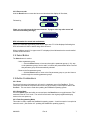
5) Cut off the tie-wrap and disconnect all the wires by loosening the screws at each
terminal. Pull the cable out of the handle.
6) Feed the new cable through the strain relief. When our standard shielded cable is used,
leave about 3/8 inch exposed, tie-wrapping the shield so as to make contact with the
printed circuit board. Then, trimming each wire to length, connect to the appropriate
terminals.
7) After wires have been correctly connected to the appropriate terminals and the correct
switch position has been selected (see wiring guides), mate the connector end of the
circuit board to the DataBank.
8) Making sure to line up the handle’s 4 screw holes with those on the DataBank, slide the
handle along the cable towards the DataBank so that the handle’s 4 screw holes sit flush
with the DataBank’s 4 screw holes. (Note: do not pull on the cable as you slide the
handle towards the DataBank. Pulling on the cable will cause the circuit boards
connector to disconnect).
9) Install all 4 screw holes to secure the handle to the DataBank (Note: do not overtighten
the screws).
10) Fully hand tighten the strain relief to hold the cable firmly in place.
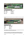
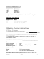
Terminal Definitions
GND Common (ground) for the sensor power, and dual current inputs
CTL-A Open drain output #1 (Gain bit 0) 200 mA max., 15 V max
CTL-B Open drain output #2 (Gain bit 1) 200 mA max., 15 V max
PWR Positive voltage to power the sensor (3-12 V)
IN+
Non-invering differential input and dual current input #1
INInverting differential input and dual current input #2
Switch Positions
2C
Two current inputs; IN+ is #1 and IN- is #2, both return to GND
dC
Differential Current inputs; use IN+ to INdV
Differential Voltage inputs; use IN+ to IN-
4.3 Wiring Guides
The following figure shows Cyclops-7 wiring to the DataBank’s circuit board using Turner
Designs’ cabling:
998-2900
Rev A
22