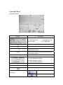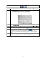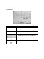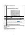
1
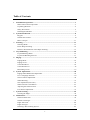
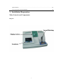
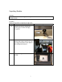
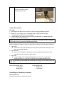
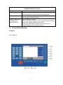
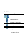
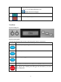
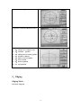
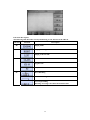
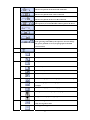
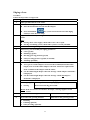
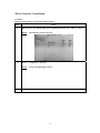
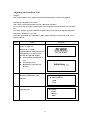
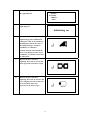
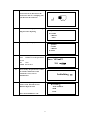
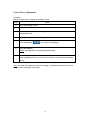
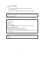
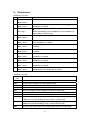
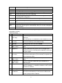
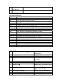
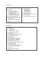
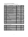
Dear Valued Customer,
Congratulations on acquiring the new AL-100-II series Edger .We
appreciate and thank you for the confidence you have entrusted in our
name.
This manaul is applicable to AL-100-II or AL-100 operation!
We recommend you read this manual carefully, for the proper use and
enhancement of the life of your new equipment.
If there’re any problems you have been met in your operation, please
contact with our consumer service department or our agent.
The information contained in this manual are not contractual and can be
modified without notice.On top of that, errors and omissions can
occur,although all is performed to avoid them.
Supplier does not assume any responsibilities or liabilities for damages
caused by errors or omissions.
1
Table of Contents
1
2
3
4
5
6
7
8
Installation/Preparation...........................................................................................................3
Main Controls and Components..............................................................................................3
Unpacking Machine.................................................................................................................4
Safety Precautions....................................................................................................................6
Installing the Machine..............................................................................................................6
System Introduction..................................................................................................................8
Keypad.....................................................................................................................................9
Scanform™ Scanner...............................................................................................................10
Basic Concepts.......................................................................................................................11
Scanning...................................................................................................................................13
Scanning Mode......................................................................................................................13
Frame Shape Scanning..........................................................................................................14
Pattern or Demonstration Lens Shape Scanning...................................................................15
Layout/Blocking......................................................................................................................16
Layout/Blocking Mode..........................................................................................................16
Layout and Blocking the Lens...............................................................................................17
Edging.......................................................................................................................................19
Edging Mode..........................................................................................................................19
Edging a Lens.........................................................................................................................21
Controlled Bevel....................................................................................................................23
Controlled Groove..................................................................................................................25
Retouching a Lens..................................................................................................................27
System Adjustments................................................................................................................28
Edging Wheel Differential Adjustment..................................................................................28
User’s Language Selection.....................................................................................................29
Screen Contrast Adjustment...................................................................................................30
Wheel Dressing......................................................................................................................31
Size Adjustment(reset sizes)..................................................................................................32
Wheel Counters Consultation................................................................................................33
Adjusting the Scanform Unit ................................................................................................34
Lens Feelers Adjustment........................................................................................................37
System Cleaning......................................................................................................................38
Cleaning the Edger.................................................................................................................38
Maintenance.............................................................................................................................39
Scanform fault code...............................................................................................................39
Scanform messages................................................................................................................39
Edger fault code.....................................................................................................................40
Edger messages......................................................................................................................41
Installing a Recirculating System..........................................................................................42
2
Specifications.........................................................................................................................43
List of accesories and consumbles.........................................................................................45
1.Installation/Preparation
Main Controls and Components
Diagram
3
Unpacking Machine
Warning
If you proceed to install your edger yourself , please do not discard boxes or any of its
packing contents.
Procedure
Follow the steps below to unpack your edger unit
Step
Action
Diagram
1
Using the 1/4 turn key contained in
accessory box, to remove the edger
cover guard.
2
Loosen and remove screw cap B by
using 14-mm wrench, remove screw cap
A by using 6-mm Allen wrench. Remove
yellow fixing frame.(keep it)
3
Remove the wedge A from the scanform
carefully
4
4
Step
Remove the wedge between lifting jack
and glass stage.
Action
Diagram
5
Loosen and remove carriage screw cap
C by the 14-mm wrench, and remove
the nut.(keep it)
6
Remove the white wedge C on the left
side
7
1. Remove the white plastic cover back
of the machine.
2. In order to screw some relative
screws facility, please remove the
white cover back of the machine.
3. Bring the carriage on the extreme
left side(operator located behind the
machine).
4. Check the set screw of the gear is
lined up with the hole. If not , turn
the gear in order to get to this
situation.
Important: Before tightening the screw,
the 1&2 marks must be lined up(make
several turns if needed).
5
8
Put back the edger cover guard by using
the key to turn three quarter
counterclockwise circle.
Safety Precautions
Warning
1.
2.
3.
Do not place the edger near or on top of a source of energy(radiator or heater).
Make sure your voltage source corresponds to the voltage specified on edger
nameplate,located on the rear of the machine.
If the machine is not going to be used for a long period of time you should unplug the
power cords from the wall outlet.
Supplier does not assume any responsibilities or liabilities for damages caused by negligence
or ignoring the safety precautions enlisted in this manual.
Installation Conditions
Before installing the machine , make sure the bench is made up of the following components:
1. The bench
z The bench receiving the machine must steady and leveled and be made up of a foot
print of about 800 *700 mm
2. The electricity
z Power outlet: 220V-16A; 110V-30A. protected with differential breaker of 30 A,
The outlet must be connected to the EARTH.
3. The water
z A water supply with a washing machine pipe, it is easily use, you can choose
pump(recirculate ) or water faucet which is used in washing machine(water).
For a well functioning of the machine, the maximum water supply pressure must be between
4 and 7 bar.
The pump and the water tank dimensions are as follows:
Water Tank: Width: 35cm
Pump: Width:12cm
Length:50cm
Height:15cm
Height:25cm
Length:20cm
Installing the Machine(continued)
Bench Preparation
Follow the steps below to prepare the bench.
6
Step
Action
1
Drill the bench as follows.
2
Place the edger on the bench by positioning it in relation to the drilled holes.
Installation
Follow the steps below to install the machine.
Step
Action
Diagram
1
Level the machine by screwing or unscrewing the
four feet.
2
Plug the drain pipe to the chassis of the machine.
3
Connect the drain pipe(s) to the machine and to the
faucet or the pump.
Note: In case of installation on direct water only,
add a filter joint contained in the accessory
box.
4
Check that the main switch of the machine is on
OFF position.
5
Scanning or directly called a graphic from the
machine.
6
Adjust the water flow by starting a cycle without
lens.(at the water supplying situation)
7
Adjustment(faucet water)
Types
Description
Main Water Spray(1)
Adjustable by operator
Must be sufficient to correctly lubricate the edging point.
Visor(2)
Not accessible by operator.
Must be adjusted while installation.
Cleaning of the back of
the edging station
(Polycarbonate)(3)
Must be adjusted as follows:
Water spray must be enough to remove the polycarbonate dust that
hit the back of edging station(near the feelers).
Water spray must not be too high to avoid a mist create an
undesired edging in ribbon of polycarbonate.
2.System Introduction
Keypad
Keys: Diagram
8
Keys: Description
The following table describes each key of the keypad.
Key
Function/description
Enters numerical values.
Confirms the numerical value entered.
Decrements the selected numerical value.
Increments the selected numerical value.
Moves the lens left during toughing and/or rimless.
Moves the lens right during roughing and/or rimless.
Releases and clamp the lens.(Press and hold the key to clamp.)
Corrects error while in entry process.
In combination with the following number key
0.
1.
2.
3.
4.
5.
6.
Language choose and Miscellaneous
Check the numbers of edging pieces
Parameter compensation
Decrease the screen intensity
Delete the saved figure
Accesses to the edging adjusting screen
Increase the screen intensity
9
7. bending revise
8. Reverse screen display(blocking screen)
Display the fixed saved figure
Validates a function.
Does an emergency stop.
Scanform
Keyboard: Diagram
Keyboard: Description
The following table describes each key of the integrated scanform ™ keyboard.
Key
Description
Function key and upturning
Function key
Function key and page down
ON
Scanning screen , displays the message ON during regular operation
Interruption of Frame Shape Scanning.
Note: This key has a blinking red LED suggest that the STOP key can cancel
this scanning task.
10
Scanning Frame Shape.
Note: This key is linked with a green LED allowing to attract your attention
to the necessity to press on this key to execute the shape scanning cycle.
Basic Concepts
Three Working Modes
The edger makes three basic operations corresponding to the three different colors
Mode
Screen
Functions
Scanning
(Blue
background)
Allows to enter the following
parameters:
z Job Number
z Frame Type
z Lens Side to Scan
z Lens PD or Bridge
z Scanning Type
Layout/
Blocking
(Green
background)
Allows to enter the following
parameters:
z Lens Side for Layout
z Vision Type
z Horizontal Decentration
z Height Decentration
z Segment Width for Near
Vision
z Layout/Blocking Mode
z Height Reference.
11
Edging
(Ochre
background)
Allows to enter the following
parameters:
z Lens Side to Edge
z Lens Type to Edge
z Lens Finishing Type
z Bevel/Grooving Type
z Lens Final Size
z Safety-Bevelings
z Edging Pressure
z Lens Polishing.
To go one mode to the other , press the following key until displaying the desired screen. And
the screens scroll in the following order:
1. Scanning Screen(blue)
2. Layout/Blocking Screen(green)
3. Edging Screen(ochre)
Scanning Screen(blue)
Layout/Blocking Screen(green)
Edging Screen(ochre)
Current Job/Previous Job
z
If your machine is not equipped with a memory extension circuit board, the buffer can
contain two jobs (First-In/First-Out) being managed as follows.
Type
Diagram
Managing
12
Current
Job:
Job
Number
in Inverse
Video
z
“-” Key:
Access to the previous job,
in the three modes.
“+” Key:
z Creation of a new job and
deletion of the previous
job,in scanning mode.
z Inactive, in layout and
edging modes.
Previous
Job
Job
Number
in Normal
Video
z
z
“-” Key:
Inactive, in the three modes.
“+” Key:
Access to the current job,in
the three modes.
3.Scanning
Scanning Mode
Function/Diagram
Functions: Description
The following table describes each scanning screen function of the ADV-II.
Function
Selection
Description
13
F0
Scanning mode
F1
Metallic frame
Plastic frame
Template
Sample scanning lens
F2
Frame Scanning right side
Frame Scanning left side
Frame Scanning both sides
F3
Distance between centers
F4
Automatic scanning
Manual scanning: Manual Stylus Positioning in the
groove-Slow scanning
Frame Shape Scanning
Procedure
Follow the steps below to scan the frame shape.
Step
Action
1
Create a job number. To do this, press the “+” key
2
Select the frame type: metallic, plastic, patterns or template
3
Select the side(s) to scan: right, left or both sides.
4
Select the scanning type: Auto or Manual.
5
Press the OK key to validate the parameters.
6
Before scanning, clean the frame with an ultrasonic cleaning device.
7
Put the frame into the frame
holder of the scanform™.
Check the eyewire joint is well
closed (tighten the joint screw).
14
8
Press the START key of the
scanform™ to scan the frame.
Result: When the scanning is
finished, the shape is drawing on
the screen.
Press the
key to
validate your entry.
Scanning Interruption
In case of problems, you can stop the shape scanning cycle at anytime.
Step
Action
1
Press the STOP key of the scanform™.
Result: The scanning is stopped, STOP and START keys are flashing, waiting to
be choose.
2
Press the STOP key again
Result: The message disappears from the screen.
Note: You can resume the scanning again. ( choose START key)
REMARKS:
When tracing the frame or sample lens,if illegal operation,the screen will show below message to
avoid machine demaged:SYSTERM STOP RUNNING!Please re-start the machine!
System Halt!!! Please Restart!!!
Pattern or Demonstration Lens Shape Scanning
Procedure
Follow the steps below to scan the pattern or demonstration lens shape.
Step
Action
1
Create a job number.To do this, press the + key
2
Select the PATTERN frame type.
3
Select the side to scan. To do this, follow the steps below.
3
If you can…
Then…
Left side
1. Press the L key.
2. Insert the pattern placing the nasal
part to the left or demonstration
lens
Right
1.
2.
15
Press the R key.
Insert the pattern placing the nasal
part to the right or demonstration
lens
Installing the template
Step
Action
4
Select the scanning type: Auto or Manual.
5
z
z
Place the lower part of the pattern
holder in order to push away the
nose of the pattern holder and to
insert the lower pins between of
the scanform clips.
Make the top of the pattern holder
rest on the upper jaw of the
scanform in the positioning lugs.
6
Press the START key of the scanform™
to start the scanning cycle.
Result: The frame scanning is in
progress and the value of the
bridge value is equal to
70.00.(it’s necessary to input
the value of bridge width or
frame’s Geometric Center)
8
Enter a bridge value or a frame distance value.
Note: The machine interprets automatically the entered value as bridge or frame
distance.
9
Remove the pattern holder.
4.Layout/Blocking
Function
Selection
Description
F0
Layout/Blocking Mode
F1
Layout/Blocking of the right side
16
Layout/Blocking of the left side
F2
Single Vision Lens Layout
Near Vision Layout(for multifocals)
F3
Horizontal millimetric decentration
Monocular pupil Distance
Binocular Pupil Distance
F4
Vertical millimetric decentration:
A vertical decentration height from the boxing center
BOX height: From the pupil center, to the lowest point of the
lens, at the bottom of the frame
F5
Segment width
F6
Graph editor
F7
Optical center:
Lens is laid out and blocked on the optical center
Geometrical center:
The optical center is displaced from the mechanical center
F8
Graphical axis of rotation
Layout and Blocking the Lens
Procedure
Follow the steps below to layout and block the lens.
Step
Action
1
Select the right or left lens to layout by F1
2
Select the vision type by F2
3
Enter the pupil distance of the customer by F3
Result: The machine interprets automatically the entered value as a total pupil
distance, monocular pupil distance or a decentration.
4
Enter the height of the optical center by F4. The machine will automatically
distinguish the input value is BOX height or MIX height.
5
If necessary, enter the segment width by F5 for bifocals.
6
If necessary, select the centering mode by F7.
17
7
Place a double-sided adhesive tape on a block.
You can use the blocks up to 100 times.
Any use beyond this limit could lead to axis or distance problems whose FLO
refuses all responsibilities.
8
Place the block inside the blocker of the machine.
9
Remove the protective paper from the tape.
10
Place and center the lens to be blocked on the screen according to the desired
layout method.
11
Press and hold the OK key to block the lens.
Comment & Layout Examples
In case of doubt regarding the lens size for cut out,you can:
z Visually inspect the lens shape on the screen, under the lens blank to verify the lens
blank is large enough or
z Compare the lens blank side diameter to the diameter value displayed at the top of the
screen.
Example:Ø 45
Lens Layout/Blocking
Diagtam
Single Vison:w/Raised Optical Center
18
Bifocal: w/28 mm Segment Width
Progressive: Laid out in Distance Vision
graph editor
z F0:change curve tangent vector
z F1:reference position
z F2:Change the size of the graphics
z F3:Perimeter changes
z F4:Observe a new graphics
z F5:Save or EXIT
z F6:down-regulation
z F7:up regulation
5.Edging
Edging Mode
Functions: Diagram
19
Functions:Description
The following table describes each layout/blocking screen function of the ADV-II.
Function
Selection
Description
F0
Edging Mode
F1
Edging of the right side
Edging of the left side
F2
Glass lens
Organic lens
Polycarbonate lens
F3
Bevel Finishing
Rimless Finishing
Grooving Finishing
Warning: Grooving is not allowed on mineral lens.
20
F4
Front Side Bevel:
The bevel is placed on the front side of the lens
1/2-1/2 Bevel:
The bevel is placed in the center of the lens
Rear Side Bevel:
The bevel is placed on the rear side of the lens
Operator Bevel(Hand Symbol):
The operator(see Controlled Bevel below) places the bevel
Front Side Groove
1/2-1/2 Groove
Rear Side Groove
Controlled Grooving:
Lens grooving controlled by the operator who can change
the groove position or curve(see paragraph Controlled
Groove below)
F5
Retouch: Lens Final Size
F6
Safety-bevel: not selected for front side
Safety-bevel on front side
F7
Safety-bevel: not selected for rear side
Thin safety-bevel on rear side
Medium safety-bevel on rear side
Thick safety-bevel on rear side
F8
Minimum Edging Pressure: Edging Thin Lens for example
Medium Edging Pressure: Edging Medium Lens for
example
Maximum Edging Pressure: Edging Thick Lens for example
Waterproof the lenses a proprietary program
Fragile lenses a proprietary program
F9
Lens Polishing:
Only for Organic Lenses
No Edge Polishing
21
Edging a Lens
Procedure
Follow the steps below to edge a lens.
Step
Action
1
Call a job aid of the bar code reader
2
Place the lens to edge in the edger, already centered and blocked, as follows.
z Place the blocked lens into the left side adaptor.
z
Press and hold the
key (or the one located at left of the edging
station) to close the lens clamp.
3
Adjust the water flow by turning the knob, located under the machiner at the
center.
Note:
z If using direct water supply, check if the water valve is open.
z If using reciculating system, check if the system is correctly installed.
4
Select the side to edge, using function F1
5
If necessary, you can modify the edging parameters
z Lens type(F2)
z Finishing type(F3)
z Beveling/grooving position type(F4)
z Safety-beveling/pressure type(F6, F7 and F8)
z Polishing option(F9)
6
Risk of collision of the adapter with the wheels.
z Two types of “small” adapters are used on the machine(19mm and 17mm
height). The use of the 19mm adapters when the 17mm ones required will
make a collision of the adapter with the wheel!
z Use the 19mm height adapter when the message “Small adapters mounted?”
is displayed.
z Use the 17mm height adapter when the message “Small flat adapters
mounted?” is displayed.
Close the visor , Press the OK key to start the edging cycle.
1.
2.
Roughing
Tracing
Do not open cover, during edging operation.
Do not touch moving parts inside.
Result: If the uncut lens is too small for the shape, a message appears on the
screen.
7
If you select the beveling function
Then enter to the beveling process
8
If you select the grooving function
Then enter to the grooving process
2.
3.
4.
Finishing
Polishing(optional)
Safety-beveling (optional).
22
9
Hold the edged lens and press the
key of the keypad(or the located at left
of the edging station) to open the right side chunk.
10
Remove the lens from the left side adaptor. Do not remove the block from the lens
until the lens size has been confirmed with the optical frame.
Safety mode
For the operator’s safety, some controls and actions have been implemented
Wheel rotation:
z The main motor starts only if the visor is closed
z Opening manually the visor stops the wheel motor and switches the machine in error
“visor function”
Clamping:
z
To clamp the lens you have to hold the
z
Starting the cycle with the clamp open will generate the warning message “Clamp the
lens before start”
key
Cycle Interruption
The edging cycle can be interrupted at any time by pressing the
key.
Result: The edging cycle stops immediately.
Edging a 1/2Eye Lens
To edging a 1/2eye lens you must:
1. Replace the standard chucks by the small chucks (Ø 19mm) located in the accessory
box.
2. Proceed to edge as any other normal lens (see paragraph Edging a Lens formerly).
23
Controlled Bevel
Screen Description
Symbol
Description
Developed curved of the lens edge and the bevel:
1. Back Side of Lens
3. Front Side of Lens
2. Bevel Apex
4. Position Index
↑
Move the bevel apex towards the back of the lens
↓
Move the bevel apex towards the front of the lens
FN+↑
Pivot the bevel apex towards the back of the lens to
current index position
FN+↓
Pivot the bevel apex towards the front of the lens to
current index position
II
Position Index
Lens profile corresponding to the current index:
1. Bevel Position from Front
2. Bevel Position from Rear
3. Value of the lens thickness
→
Move position index view of the lens clockwise
←
Move position index view of the lens counterclockwise
Allow the re-trace of the lens
Allow the selection of the following
bevel types:
Front Bevel
Rear Bevel
24
1/2 1/2 Bevel
Follow the steps below to control the bevel position after roughing and feeling.
Step
Action
1
After roughing and lens feeling cycles:
z Modify the bevel type if necessary, aid of the F5 key
Result: The new bevel position is released
z If necessary feel the lens again, aid of the F9 key.
2
Move forward the curved drawn by the bevel towards the front or the back, aid
of the ↑ and ↓ keys.
3
Sweep the lens around to display the lens section, aid of the ← and → keys.
4
When the bevel position is correct, press the“OK”key to start edging.
5
Hold the edged lens while pressing and holding the
key of the
keypad(or the one located at left of the edging station) to open the right side
shaft.
6
Remove the lens from the left side adaptor, making sure not to remove the block
as some re-edging might be necessary for proper sizing of lens.
25
Controlled Groove
Screen Description
Symbol
Description
↑
Move the groove towards the back(0.4 mm maximum)
↓
Move the groove towards the front(0.4 mm maximum)
FN+↑
Pivot the groove towards the back of the lens
FN+↓
Pivot the groove towards the front of the lens
II
Position Index
Lens profile corresponding to the current index:
1. Front Side Distance from the front edge of the groove
2. Rear Side Distance from the back edge of the groove
3. Value of the lens thickness
→
Move position index view of the lens clockwise
←
Move position index view of the lens counterclockwise
Re-feel the lens
26
Procedure
Follow the steps below to control the lens grooving.
Step
Action
1
After roughing and lens feeling cycles, select:
z The grooving type, aid of the F5 key.
Result: the position of the groove has been altered.
z Detection of lens again, aid of the F9 key.
2
Move forward the curved drawn by the grooving towards the front or the back,
aid of the ↑ and ↓ keys.
3
Sweep the lens around to display the lens section, aid of the ← and → keys.
4
When the grooving position is correct, press the OK key to start rimless,
polishing(possibly) then grooving cycles.
5
Hold the edged lens while pressing and holding the
key of the
keypad(or the one located at left of the edging station) to open the right side
shaft.
6
Remove the lens from the left side adaptor, making sure not to remove the block,
as some re-edging might be necessary for proper sizing of lens.
Retouching a Lens
Prerequisites
Before retouching a lens, make sure of the following:
z The lens block has not been removed from its original lens placement
z The edging parameters have not been altered.
27
Procedure
Follow the step below to retouch a lens after edging.
Step
Action
1
Place the lens in the edger again.
2
If the lens to retouch comes from the previous job, press the
the following step.
3
Select the side to retouch aid of the
F1 key.
4
Press the F5 key.
Result: The size value appears in
inversed color.
5
Enter the value to revise the size, by:
The + and/or - key.
Note: The correction value is always in a negative form and is limited to a
minimum increment of 0.5 mm.
-
key, if not go to
6
Press the
key.
Warning: The retouch cycle can be performed only when the correction value has
been entered.
7
Hold the edged lens while pressing and holding the
key of the keypad
(or the one located at left of the edging station)to open the right side shaft.
28
6.System Adjustments
Edging Wheel Differential Adjustment
Condition
To adjust the wheel differentials, the system must be in rest position(not in scanning or
edging process).
Procedure
Follow the steps below to adjust edging wheel differentials.
Step
Action
1
When you are in scanning mode, press simultaneously the
2
Result:
FN and
2
The following screen comes up(default values).
3
Press the
4
key until the appropriate value is darken.
Enter the value of the desired wheel differential aid of the keypad.
5
Press the
key to validate your entry.
6
Go to the step 3 of this procedure until you adjust all the necessary wheel
differentials.
7
Press several times the EXIT key to get back to the working mode.
29
keys.
User’s Language Selection
Procedure
Follow the steps below to select the language.
Step
1
Action
When you are in scanning mode, press simultaneously the
FN and
0
keys.
Result: The following screen comes up.
Language
Contrast
Visor detection
Polishing cycles
2
Press the
key facing the line User’s language: English until you display
the desired language:
z English
z 中文
3
Press F7 and EXIT keys, the screen will appear one language you choose
30
Screen Contrast Adjustment
Description
There are 3 types of adjustment to improve visibility of the lens on the scanform™ screen.
Type
Function
Possible Use
Inverse
Colour Key
Improve the visibility of the bifocal
segment
Bifocal Lens Layout
Screen
Brightness
Adjust the brightness of the
recorded shape with the screen
Adapts to the ambient light in the
working lab
Polarizing
View Finder
Adjust the contrast of the lens with
the screen
Improves view when decentering of a
dark lens
Inverse Colour
The inverse colour may be changed at any time, by pressing the
FN
and
9
keys.
Result: The screen reverses colour.
Notes: The colour will default back to black on white after the system has been switched off.
To return to black on white, press again the FN and 9 keys.
Screen Contrast Adjustment Keys: FN + 0. Choose the second option: Contrast adjust
z Press F2, choose “–” : Allow to darken the screen contrast
z Press F1, choose“+”: Allow to lighten the screen contrast
Polarizing Visor
To adjust the brightness of the recorded shape with the screen, rotate the polarizing eyepiece
in either direction to suit you best.
31
Wheel Dressing
Procedure
Follow the steps below to dress a wheel
Step
1
Action
When you are in scanning mode, press simultaneously the
Result:
FN and
5
keys.
The following screen comes up.
2
Select the line dressing : Manual dressing
3
Load the burnishing stick adapted to the wheel to dress,
4
Press the START key, dress the wheel by burnishing stick
5
When the dressing is completed, remove the burnishing stick from the edger.
6
Press the EXIT key.
32
Edged Lens Size Adjustment(reset sizes)
Procedure
Follow the steps below to adjust the sizes.
Step
1
Action
When you are in scanning mode, press simultaneously the
Result:
FN and
5
keys.
The following screen comes up.
2
Select the line Lens size adjustment.
3
Insert a lens with a diameter≥ 60 mm.
Adjustment
Lens Using
1.
Mineral roughing
Mineral
2.
Plastic roughing
Plastic
3.
Finishing Rimless
Mineral
4.
Finishing bevel
Mineral
5.
Polishing Rimless
Plastic
6.
Polishing Bevel
Plastic
4
Press the OK key and choose corresponding number key, insert the lens according
to the hint.
5
When the edging is completed, measure the diameter of the edged lens with a
calliper.
6
Enter the measured value with the keyboard.
7
Press the Valid key to confirm the size adjustment.
8
When the size adjustment is completed, save your adjustment.
33
Wheel Counters Consultation
Procedure
Follow the steps below to consult the wheel counters.
Step
1
Action
When you are in scanning mode, press simultaneously the
Result:
2
Press
Result:
3
The following screen comes up.
“+” (Pg Dn) “-” (Pg Up)
Screen will upturning or down
Press EXIT back to the working screen
34
FN and
1
keys.
Adjusting the Scanform Unit
Purpose
This section enables you to adjust the Scanform unit using the various tool supplied.
Running the Adjustment Procedure
This “Start” option will actually start the calibration procedure.
It’s a step by step procedure, requiring the use of 4 specific tools, located into the user black
box.
For safety purpose, previous calibration values will be preserved if the ongoing calibration
fails before reaching it’s very end.
Once fully performed, new calibration values will be taken into account, only if the “Save”
option is chosen.
Step
Action
1
After start the machine, the screen
display as right side:
Hold F2 key 2 seconds
Caution!hold the F2 key till the icon
is disappear. If you are not enter
into like the right side display:
z Wait until the initialization is
over
z Turn off the power
z Hold F2 key again after 20
seconds
2
3
Diagram
Initializing ┅
Press F3 key to make
►ADJUSTMENT like right
diagram:
CONFIG…
► ADJUSTMENT
MTR
EXIT
Press START key to confirm the
right diagram:
►QUERY
START
CHECK
EXIT
35
4
5
Press F3 key to make► START like
the right diagram:
QUERY
►START
CHECK
EXIT
Press START key to confirm the
right diagram:
Initializing ┅
6
Put into the No.3 corresponding
adjustment jig after initialization.
Change the value by F1 and F3, let
the displayed value is the same to
the adjustment jig’s, and press
START key to confirm it.
Caution! Altered value should the
same as the displayed value. Press
START key to confirm it ,then start
to calibration..
7
Remove the No.3 tool after
adjusting, insert the No.2 tool. The
same operation to the below step 6
8
Remove the No.2 tool after
adjusting, insert the No.4 tool to the
No.7 clamping tool. Insert this tool
to the scanform. The same
operation to the below step 6
36
9
Remove the No.7 tool, remove the
No.4 tool from it, then insert the
No.5 tool to the No.7 clamping tool,
put this into the scanform
10
The screen will display like the right
diagram after adjusting
11
QUERY
►START
CHECK
EXIT
Press F3 key to display ► EXIT
QUERY
START
CHECK
► EXIT
12
13
14
Press START key to confirm it
Save
whether save the parameter
or not
F2
save
STOP not to save
Press F2 key the parameters will be
saved. The calibration of the
scanform is over, start to
initialization.
Save: YES→F2
NO →STOP
Initializing ┅
Press STOP key the parameters will
not be saved. Exit this screen
Resume adjust if need
►CONFIG…
ADJUSTMENT
MTR
EXIT
If not choose►EXIT to exit
37
Lens Feelers Adjustment
Procedure
Follow the steps below to adjust the scanning system.
Step
Action
1
Go to the scanning screen.
2
Press simultaneously the
3
Press the Yes key , the indicate will appear
Assemble 01# tool
4
Put adjustment tool on the lens adapter shaft(left side).
FN
and
7
key.
5
Press and hold the
key to close lens clamping.
6
Press the Valid key.
Result: The adjustment is automatically performing.
7
The clamping will open automatically after finish the adjustment, take off the
pattern jig and press Save to preserve the new data, come back to the scanning
screen.
Note: This calibration influences the bevel tracking. A calibration performed poorly can
induce a bad work quality of the edger.
38
7.System Cleaning
Caution
z Put the frame on the untrasonic tank for cleaning before collection
z Using new adhesive pad
z Replace the block regularly, one block can be used no more than 100 times
Caution
Do not use any type of spray hose to clean your system. Avoid any heavy splashing or
spraying that may penetrate the system’s scanning and keyboard/interface. This can cause
electrical damage to the system.
Never use chemical solvents, agents or derivatives of such products as:
z Acetone
z Trichlorethylene
z Benzene
z Kerozene
z Lighter Fluid or
Any product that claims”Do not use on plastic or painted surfaces”or that contains
CHLORINE, AMMONIA, SODA.
These products directly or even by their simple vapors:
z Might alter the structure and appearance of your system
z Usage of any of these materials will void any guarantee or warranty of the whole unit or
its components.
!! Never manipulate the lens feeler pliers located in the edging station.
Supplier does not assume any responsibilities or liabilities for damages caused by errors or
omissions.
39
8.Maintenance
Scanform error code
No.
Error code
Cause and solution
1
Err Code: EP08
Redo ->Start
Scan pattern error,press START key to restart scan.
2
Err Code: EM04
Redo ->Start
Patterns or demonstration lens are incorrectly insert, press
START key to confirm.
3
Err Code: ET03
Str<-,Stp->
Rods or clip moving error or insufficient stroke.
Restart self feeling by press START key, or press STOP key to
skip it and go to the next step.
4
Err Code: EM01
Redo ->Start
Incorrectly frame insert, press START key to confirm.
5
Err Code: EP02
Redo ->Start
If scan failed three times, restart to scan by manual mode,
press START key to confirm.
6
Err Code: ET01
Redo ->Start
Rods move outward error or timeout .Press START key to
confirm.
7
Err Code: ET02
Redo ->Start
Rods move inward error or timeout. Press START key to
confirm.
8
Err Code: EC03
Redo ->Start
Carriage error, loss of steps, or the stroke switch fault. Press
START key to confirm.
9
Err Code: ER03
Redo ->Start
Large rotation error, loss of step or the stroke fault. Press
START key to confirm.
10
Err Code: EP05
Redo ->Start
Probe insufficient stroke when it is on the self-checking. Press
START key to confirm.
11
Err Code: EP07
Redo ->Start
Probe insufficient vertical stroke when it is on the
self-checking. Press START key to confirm.
Scanform error code
Error
code
Cause
0101
The Jaws motor unable to start the loosen switch
0102
The Jaws motor unable to start the tighten switch
0103
The rotary steper motor cannot start the switch
0104
The translational steper motor cannot start the switch
0201
There’re something on the clamping role when it is self-testing
0202
The rotary steper motor is in running trouble when it is self-testing
0203
The translational steper motor is in running trouble when it is in self-testing.
0204
The radial trolley move to outwards is not enough when it is self-testing,
<5000yards, cause the blocking moving or motor \encoder fault
0205
The probe pole height moving position is not enough when it is in self-testing,
<2000yards,cause the blocking moving or motor \encoder fault
0206
The probe pole cannot achieve the settled height when it is in self-testing
40
0301
The calibration of the height coefficient is in fault
0302
The calibration of the radial coefficient is in fault
0303
No feeling the jaws when in the calibrating
0304
Probe can not arrive the settled height when in the calibrating
0305
Scanning fall of pole when in the calibrating
0306
The caculated parameters are error when in the calibrating(maybe the jaws
are putting on the wrong place)
0401
Cannot feel the frame or bracket when it is scanning.
0402
Cannot feel the templete or sample lens when you scan the templete or sample
lens
0403
Fall away the pole when you scan the templete or sample lens
0404
Cannot enter into the groove automatically when you scan the frame,please
operate by hand
0405
Failure scanning
Clear Jaws!: indicated that ensure there’re no anything on the jaws.
Fail!:Failure scanning
Scanform message
No.
Indicate message
Cause and solution
1
! Again->Start
Exit->Stop
The value of parameter obtained from the calibration is
incorrect.
Press START key to re-calibration or Press STOP key to exit.
2
Save? Yes->F2
No->Stop
After finish the scanform calibration , save the data by Press
F2 or Press STOP key to exit without saving.
3
Stand By...
Waiting prompt after enter into“MTR”.
4
No Pattern !
Redo ->Start
Incorrect pattern insert, press START key to insert pattern
again,
5
Height Err!
During calibration of the pattern, incorrect height about
entrance of groove is occurred, press START key to enter into
the groove again.
6
Rod Touch Err!
Str<-,Stp->
The top of Rod collet touching is in trouble, press START key
to probe Rod collet again or press STOP key to skip this step,
access to the next action.
7
Incorrect tool !
Redo ->Start
Installing incorrect tool, press START key to calibration
again.
8
Rod Test Err!
Redo ->Start
Incorrect calibration of Rod coder, press START key to
calibrate again.
9
Templet&Scan Err!
During calibration of the pattern, the wrong templet
choosen ,installing or a mistaken caculation of the relevant
parameter is occurred.
10
Initializing...
Prompt for the scanform initialization.
11
Error! =>start
to calibrate!
System parameter has not be saved or the saved parameter is
incorrect. Press START key to enter into the calibrate unit
for the system parameter calibrate.
41
12
System Error!!!
Please Restart!
Cut off the power then restart the machine.
13
Stylus Error!
Back Manually!
Face to a serious error, Press START key to exiting.
Edger fault code (Edging)
Error code
Cause
0101
Grooving swing switch is in trouble
0102
Grooving swing in switch is in trouble
0103
Edging pressure sensor has no change
0104
Camber coder has regulation resistance’s testing trouble
0105
Clamping electric motor has tighten trouble
0106
Clamping electric motor has loosen trouble
0107
Camber system cannot test closing
0108
Camber system cannot test opening
0109
Raise and down to the destinated position is in trouble
0110
Raise and down’s switch fault
0111
Blocking switch fault or motor fault
0112
Translational to the destinated position is in trouble
0113
Translational switch fault
0114
Whirl reached pointed position is timeout
0201
Downward shift is torn off when it is in initialization
0202
Upward shift is blocking when it is in initialization
0203
Raise and down’s switch fault or motor in trouble
0204
Translational switch fault
Edger message
1
Confirm reset correction value?
Confirm reset correction
value(dafault)
2
Edging in progress!
Edging in progress
3
No data or lens for retouch
No data or lens for retouch
4
Lens size not decrease, Retouch impossible
Lens size not decrease, Retouch
impossible
5
Grooving lens cannot retouch!
Grooving lens cannot retouch
6
Clamp the lens before start!
Clamp the lens before start
7
Radius too big!
Radius too big,unavailable to edging
or camber scanning.
8
Radius too small !
Radius too small,unavailable to
edging or safety beveling
9
Small adapters mounted?
Whether install the small adapters
10
No data for edging
No data for edging
11
No 01# tool found!
01#tool is not installed
42
12
Lens Feelers Adjust,Left range not enough!
Lens Feelers Adjust,Left range not
enough (lower than 10mm)
13
Lens Feelers Adjust, Right range not
enough!
Lens Feelers Adjust, Right range not
enough (lower than 20mm)
14
Clear the Adapter!
Take the things out of the adapter
15
Bevel too much at the back
Bevel too much at the back
16
Edging=>Cabin door open
Cabin door is opened when it is
edging.
17
Lens feelers=>Out of range
Lens feelers scan no lens or the probe
is out.
18
Groove=>Lens too thin
Lens is too thin to guoove (1.5mm)
19
Lens feelers=>Lens too thick
Lens is too thick in the lens feelers
test
20
Abort the Edging task?
Abort the Edging task
21
Edging=>Time out,Plate contact may fail!
Roughing 5 min, finishing 3 min.
22
Confirm reset user records?
Confirm reset user records
23
File already opened!
File already opened
24
Scanning in progress!
Scanning in progress
25
Scanformer does not respond!
Scanformer does not respond
26
Tracing=>delete all job file!
delete all job file
Installing a Recirculating System
Warning
Only pumps that comply with the relevant safety requirements are permitted:
z 220V: Pump voltage
z 200W:Power availiable (for the pump).
Procedure
Follow the steps below to install a recirculating system.
Step
Action
1
Place system assembly under workbench.
2
Feed the following through the pre-drilled holes on the work bench top:
z Main Supply Water Hose
z Visor and Polycarbonate Supply Water Hose.
To do this, see the diagram below.
3
Connect the recirculating system’s power cord into the electrical outlet.
4
Fill three quarters of the tank with water .
43
Specifications
Specifications: ADV-II
Scanform™ Scanner
z
z
z
z
z
Automatic Initialization
Automatic Frame Positioning
Automatic Insertion of the Stylus
Scan frame, pattern,lens
Automatic detection of insertion of
a pattern or demonstration lens
z
Automatic Tracing in 3D of two or one
circles as required
Frame groove angle automatic measurement
Tracing frame Diameter:
* Maximum: 80 mm
* Minimum: 21 mm
z
z
Layout/Blocking
z
z
z
z
z
z
Serve controlled lens blocking
Lens blocking by Adhesive only
Patient’s data entered via the keypad
(minimum step: 0.10 mm):
*Horizontal input: Offset PD, Mono PD,
or full PD.
*Vertical Input: pupil height
gap,BOXing mode or MIX mode pupil
height
Note: All data combinations are accepted by
the computer:
*Blocking cross for single vision,
bifocal (with adjustment of bifocal
segment width), progressive
*Adapter / grinding wheels
anti-collision device(warning of the
operator with small sockets)
Operator Interface using lcons
LCD colour screen
Screen Contrast and Video Reverse
Control
z Lens Wheels Choice:
*Roughing: Glass or Plastics(CR39,
Polycarbonate and High Index Organic)
*Finishing: Controlled beveling(Front
Face, Rear Face, /2-1/2, Frame Base,
Lens Base, Rimless, Polishing,
Safety-bevel, Grooving)
z Assembly Job Number Display
z Optical Center Blocking
44
Edging Station
z
z
z
z
z
z
z
Automatic Initialization
Lens front and rear face tracing: 3D
Equipment
* Roughing Glass Edging
* All Plastic Edging(CR39, High
Index, Polycarbonate)
* Bevel/Rimless Finishing Edging
* Bevel/Rimless Polishing Edging
Automatic Clamping Pressure
Edging pressure controlled according
to lens material
Safety-beveling: Front and/or Rear
Sides
Optional memory extension: 300 jobs
z
z
z
z
z
z
Specifications
z
z
z
z
z
z
z
z
z
z
z
z
z
Dimensions:
* Width: 660 mm
* Depth: 620 mm
* Height(visor close): 430 mm
* Height(visor open): 520 mm
Weight: 70kg
Power Supply: 230 V/50 Hz 110V/60Hz
Power Consumption: 1000 W
Pollution Degree: 2
Installation Category: II
Ambient Temperature: 3℃ to 35℃
Relative Humidity: 10% to 80%
Maximum Water Pressure: 7 Bar
Maximum Pump Pressure(with Pump): 7 Bar
Output of Pump Outlet:
* 220V: Supply Voltage
* 200W: Power available(for the pump)
Fuses to be used for 220 V edger:
15A , 3A , 8A
Fuses to be used for 110 V edger:
30A , 3A , 8A
45
Quick Connect Water Connection or one
Lens Edging Diameter:
* ≤ to 80 mm
* Rimless: 17.75 mm
* Bevel: 19.50 mm
Drain Size: Ø 100 mm
Water supply Pressure: from 4 to 7 bars
Network Connection
Lens Grooving in 0.6 mm Nylon yarn
List of accessories and consumables
The following table lists the accessories delivered with your edger.
Accessories
S/N
Accessories name
1
Tracing adjustment tool
2
Scanform parameter setter
Tracing adjustment tool(roundness)
3
Tracing adjustment tool(quadrate)
4
5
Machine rack adjustment tool
6
Lens pattern adjustment tool
7
Lens clamping adaptorφ19 mm
8
Lens clamping adaptorφ17mm
9
Lens clamping cushionφ19mm
10 Lens clamping cushionφ17mm
11 acetabula
12 acetabula
13 Fixing cover set
14 Lens clamper
15 Fuse
15A
17 Fuse
8A
18 Fuse
3A
19 Display window protector cushion
20 adhesive pads(box)
Specs.
1# tool
2#tool
3#tool
4#tool
5#tool
7#tool
Mediums
Small
Mediums
Small
Mediums mode
Small mode
Mediums mode
φ6*30mm
φ5*20mm
φ5*20mm
Thickness1mm
Quantity
1
1
1
1
1
1
1
1
2
2
6
4
1
1
2
2
4
2
1
21
Key 6 facets
1.5-6mm(set)
1
22
23
24
Wrench
NO.14
Flat glass lens(used in wheel blocking) thickness 2.5mm
ADV.-II User manual
1
10
1
List of water tank accessories
S/N
Accessories name
1
Plastic water case
2
Pump
3
Rainspout
4
Screen cloth sets
5
Water pipe hoop
6
Washing machine pipe
Specs.
220v200w
φ100*800mm
46
Quantity
1
1
1
1
1
1