1
Ge Quick Start Guide
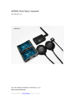
1 Assembly
Note:
The power supply range of MC (Autopilot) and WIFI is 3s~6s(Power remains a
little), namely 10.8V~25.5V
10.8V~25.5V,, MC provides 5.7V power to RC receiver automatically
automatically,, no
need to add any out-built power module. After correct connection and powering it,
the autopilot will complete initialization in few seconds and LED light starts to blink in
red for three times continuously , indicating the connection is correct and motivated
successfully.
The above "the light blinks in red for three times" is a sign to check whether all
hardware are working normally or not, all data connection is based on this. After
powering if no "the light blinks in red for three times", please contact Zero UAV
(Beijing) Intelligence Technology Co. Ltd. or its distributors directly. Otherwise,
please check the assembly carefully refering to the above illustration.
Attention: Any wrong connection of IMU or GPS may result in burning out
the devices.
ESC, the motor at work will produce severe magnetic interference, GPS and
magnetic sensor module must be by non-magnetic (non-iron), rack-mounted
away from the motor, ESC (8-axle vehicle), and the arrowdirection toward the
nose. Otherwise, the aircraft GPS mode will seriously circle can not be correct
hover.
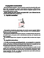
2 Router Setup
Step1: Download YS-GCS.
It must be installed to the Mobile memory card. Android
system can be installed automatically via running file installation once in the file
” Apple
manager. Apple system can be installed after APP jailbreak, please refer to
to”
”
Installation Instructions
Instructions”
”YS-X6-Serial No.
”
Step2 : Use wireless router to build AP. Set SSID of the router as
as”
No.”
(Note: The letters must be in Capital), password is 82890430, and use encryption
method WPA2-PSK AES. Router IP must be 192.168.1.1 (The mobile with hotspot
function can be also instead of router, but must make sure the mobile can set up SSID
and password, in same way IP should be: 192.168.1.1)
Step3: Open WLAN on mobile/tablet to connect to router. (All the flight data shall be
saved to YShj in mobile after connecting Wifi data, the YShj file can be replayed
e kind of tool of computer.)
through on
one
Only same SSID: YS-X6-Serial No. Password: 82890430
3 Installation Guide
After connecting all data, you can set up the below options as showing in
” of GCS “Settings
” (If the data is not connected, please read the
“ Installation Guide
Guide”
Settings”
above two steps carefully)
Channel Calibration
(1)
(1)Channel
Check CH5 & CH6, set up F/S (Fails safe)
(2)
(2)Check
ESC stroke calibration
(3)
(3)ESC
Set up aircraft type and parameters. Fill in local magnetic declination ( West is
(4)
(4)Set
positive, East is negative)
Check the configuration direction of IMU & GPS
(5)
(5)Check
After completing the installation guide, can test fly manually.
(Please refer to the below website for magnetic declination)
http://www.ngdc.noaa.gov/geomagmodels/struts/calcDeclination
4 Magnetic Course Calibration
It
It’’s no need to calibrate the magnetic course in manual mode .But in GPS mode , the
magnetic course calibration must be finished before take-off .The magnet on aircraft
or neighboring magnetic filed can affect the magnetic compass to read the Earth
Magnetic Field, thus may reduce controlling precision of Multi-Rotor aircraft even
effect obstacles. Calibrations can reduce these effects to make sure the MC work
normally in defective magnetic environment. Magnetic field data will display
immediately after calibration but can not be saved to autopilot , the data can
can’’t be
obtained any more after powering off.
Calibration Steps
” after clicking “magnetic compass calibration
”.
Step 1 : Select “level calibration
calibration”
calibration”
After confirmation, it will display whether AP received the order of level calibration on
magnetic compass in the middle status bar. If there is a successful display there, you
e the aircraft 2-3 laps slowly, can ask you
can start the level calibration: level rotat
rotate
yourr
” window, please try best to make
assistant to monitor the attitude angle in “Data
Data”
sure pitch and toll is within 3 degree when rotating ( example: left 2/lift 2 is OK, but
left 3/lift 2 is not good; It
It’’s ok to exceed 3 occasionally, AP shall stop collecting data
while exceeding 3 degree and continue to collect data when recover 3 degree
less),also can look the blinking light directly which connecting with AP, blinking light
meet attitude requirements, off light means the attitude is too big.
Step2: After completing level rotation of 2-3 laps, make the craft head face the
” in GS, after
ground vertically, then select “Magnetic compass Vertical calibration
calibration”
sending out please confirm whether it
it’’s successful in the status bar, and then the roll
and pitch will change close to 0 degree slowly via checking the attitude angle in
”(namely changed reference coordinate system, it
“Data
Data”
it’’s level when the craft head
face the ground).Then take the craft head as Axis and keep attitude angle within 3
degree, level rotate 2-3 laps. You can also check the blinking lights which are
connecting with AP, blinking lights meet attitude requirements; off lights indicate a
too big attitude.
Step 3:
Get through above operation, finished magnetic compass calibration, the
s of seconds,
GS can switch to RC Interface automatically, after waiting for score
scores
mobile will display the magnetic sensor data of AP, only look the red and blue circle in
the middle of cross coordinates, if they are close to standard round, then indicates a
successful calibration and data in good condition.
After correct assembly and successful magnetic compass calibration once, no need
to recalibrate without any constructional reconfiguration or only upgrade the
firmware.
5 Control Priority
User must select two 3-position switches and set them to CH5 & CH6 by RC
transmitter.
manual altitude holding /GPS 3
Three modes can be switched through CH5, Manual/
Manual/manual
namely GPS mode
.CH6 is
modes. CH6 can work only when CH5 stays at position 3 (namely
mode).CH6
navigation /Auto-returning home &
for switching modes among Auto-hovering/AutoAuto-hovering/Auto-navigation
landing.
” or “Receiver on
” in
The switch of RC receiver is button which showing “Receiver off
off”
on”
GCS, used to turn off/on the RC receiver on craft ,namely any operation is useless for
” , which equals there is no RC receiver on the craft.
aircraft if receiver displays “RC off
off”
It is not suggested to close the receiver ( RC off) if user isn
isn’’t familiar with the system.
Mobile RC Status means whether the cross operation is enabled or not in the mobile
”, there is a “round circle
”
RC interface, enable the GS software and click “ RC on
on”
circle”
” ,indicating “Mobile RC status ”has been enabled “.Select “ RC
showing on the “cross
cross”
” ,there is no round circle on the cross ,indicating “Mobile RC status ” has been off.
off
off”
RC
Status
CH5
Status
Mobile RC
Status
CH6
Status
Enable
RC off
X
Automatical
X
CH6
Mobile
”
“Control
Control”
on
RC on
CH5 Auto
position1
CH6
position2
CH6
position3
(In
CH6
position
position1
3)
Mobile
”
“Control
Control”
off
losing WIFI or signal exceeding 10s, auto-returning home and landing. (This mode
1
is not commended to hobbyists.)
CH5
X
Priority
” showing on the “cross
”. When
When controlling by mobile, there is a “round circle
circle”
cross”
X
ly
Manual
Craft Status
CH6
position2
CH6
In full manual mode, it
it’’s controlled by RC transmitter only.
Note: No strong actions/ No high speed when flying in manual mode.
2
” showing on the “cross
”, please
When controlling by mobile, there is a “round circle
circle”
cross”
check the mobile status, it has nothing to do with the RC Transmitter.
” mode. ( Make sure the
Enabling waypoints on mobile can get into “Auto-navigation
Auto-navigation”
waypoints is uploaded)
3
” mode
“Auto-return home & landing
landing”
” mode , if the throttle is in the minimum, craft may go down fast,
“GPS auto-hover
auto-hover”
meanwhilethe throttle should be maintained in middle-position.
” mode. ( Make sure the
Enabling waypoints on mobile can get into “Auto-navigation
Auto-navigation”
waypoints is uploaded)
uploaded))
4
” mode
“Auto-return home & landing
landing”
position3
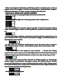
Note : X represents any kind of status .When mobile transmitter is turned on ,there is a round circle showing on the
cross. When Mobile transmitter is turned off , there is no round circle showing on the cross .RC status is “receiver
on ”and “receiver off ”status in GS .priority:1 represent the most.
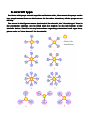
6 aircraft type
For those with props on both top side and bottom side , blue means the props on the
top, purple means those on the bottom. In the other situations, all the props are on
the top.
” item in
The arrow in the figures means the head of the aircraft ,the “aircraft type
type”
the parameter settings ,can be filled with the number on the left bottom of the
aircrafts below. There is no any instructions regarding customized craft type here,
” for the details.
please refer to “User Manual
Manual”
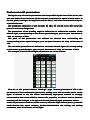
Custom aircraft parameters
Mixing the way of custom parameters can be specified by the user of the motor, the
user can define the scale factor of the increase or decrease in speed of each motor in
the roll, pitch, turning to the application of the Alien" and other unconventional layout
of multi-axis rack.
The parameter definition of the throttle: all 100, fill out the error will cause the
power is turn very dangerous!
The parameters of the heading angle is defined as: to achieve the rotation of the
aircraft right, corresponding to the motor speed changes, year-on-year decreases of
-100, an increase of 100.
The pitch of the parameters are defined as: aircraft bow overlooking the
corresponding motor speed changes, year-on-year decreases of -100, an increase of
100.
The roll of the parameters are defined as: when the aircraft right roll, corresponding
to the motor speed changes, year-on-year decreases of -100, an increase of 100.
For example: 4-axis X-word flight parameters are set as follows:
Must be at the ground station "Settings" page "custom parameters" fill in the
parameters of the confirmation (parameter setting error will cause the power or the
types of aircraft to 10, the motor immediately high-speed rotation is strongly
recommended that users willall to remove the propeller, in order to ensure absolute
security) will be changed to 10 types of aircraft (Aircraft type) parameter values
,
access to parameter confirm rewrite success, after the flight control power, push the
small throttle low speed rotation, double-checkwhether the mixing and setting
consistent, after the success of the flight.
、stop rotation and F/S
7 Enable motors
motors、
Enable motors protection
Any time after landing or before take-off, only if it is manual mode and the throttle
stick is at the bottom position,
the motors can be locked up completely after 5
s won't rotate even if push the throttle stick
seconds ;After locking up
up,, motor
motors
stick.. The
” on mobile or broken rod.
insurance only can be enabled through “enable insurance
insurance”
Motor Off
Only in manual mode and without holding altitude
altitude,, the motors stop rotating with
pulling the throttle stick back to the bottom. Other time, if pull back the throttle stick
to the bottom, the motors won
won’’t stop rotating but only decrease altitude
altitude.. Whenever
need to stop the motors urgently, below ways can help:
(1), Switch CH5 to position 1, namely in manual mode but without holding altitude
altitude,,
what
what’’s more the throttle must be in the minimum.
" on mobile RC interface ;
(2), when mobile phone select "RC off", select " motor off
off"
" , according to the method (1);
Or turn on the receiver "RC on
on"
ing and landing on the ground, select "motor off" on mobile RC
(3), After auto-return
auto-returning
interface and confirm; Or turn on the transmitter
transmitter,, according to method (1);
(4)
(4),, After landing on the ground in holding altitude or GPS mode
mode,, press the cross
down continuously , namely the landing throttle or RC throttle are in the bottom all
op rotating slowly till shut down completely and lock up .
the time, motor will st
stop
Wifi signal loss
(1) when RC is turned on , if the wifi signal loses more than 1 second, then transfer
the right of control to the transmitter
transmitter;;
" (RC close
d), all of transmitter operation is
(2) when user select " receiver off
off"
closed
invalid, the right of control are managed as follows:
A. In the case of " waypoints flight " , the waypoints flight will not be influenced if
ere is no wifi signal, and go back to the first point to hover after finishing flight ,
th
there
then estimate whether wifi signal has recovered or not , if unrecoverable ,then
manage as following;
B.
ight ”or aircraft hover in the first po
sition after
when it
it’’s not “ waypoints fl
flight
position
finishing waypoints, wait 10 seconds if the wifi signal loses, ,and continue to operate
if the signal recover; If there is no signal after 10 seconds, then enable the temporary
ding ; if the signal recover again, then stop returning instead of
returning & lan
landing
ing & land
ing
",
hovering. Hovering can accept mobile cross control and " return
returning
landing
ing",
" switch control. Continue to return and land if the
"enable waypoints ", " motor off
off"
signal is not recovered,.
se
RC signal lo
lose
Users must refer to the instruction of RC transmitter to set F/S correctly ,and set
CH5 to position 3,CH6 to position 1, throttle to the center(tips are in the installation
If enable F/S for any reason in “RC on
” status ,the RC transmitter will be
guide).
guide).I
on”
ed to aut
o- hover stat
us
continue waypoints for 3 seconds in auto-waypoints
switch
switched
autostatus
us(continue
auto-waypoints)
to wait for 3 seconds .Start to return if the signal can
can’’t recover after 3 seconds.
8 Mobile Remote Control
” of “ GPS mode
”, the
During flight, when RC Transmitter is switched to “Auto-hover
Auto-hover”
mode”
craft
shall
get
into
auto-hover.
Meanwhile
click
GCS
on
mobile
mobile→
“enable
” to enable or disable the control operation.
control/disable control
control”
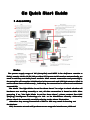
Mobile remote control operation ways as below:
RC ON
Operation method
Aircraft status
Circle area
Red: Un loacated; Green: located.
Keep still
Position hold
DO NOT touch any area
Position hold.
Operation
Climb/
Decline/rotat
e
1.
2.
3.
Press the circle and move up/down
1. move back and front
Press the circle and move left/right
2. move left and right
Press the circle and move left top, left 3. Move
bottom, right tip, etc.
lefttop,leftbottom,etc.
click the circle and move in the range of the
red cross:
1.top
2.bottom
3.left
4.Right
Note
(1)
The distance to the red dot means the
flight speed. The farther ,the faster.
(2)
Press=moving, release=stop moving
(3)
Release=position hold immediately
(4)
The Maximum speed is 2.5 m/s
1、Climb
2、 Decline
3、rotate to the left
4.rotate to the right
Notice
Notice:
In GCS “Settings
” , there is “change
change altitude
” there, when in auto mode and the
Settings”
altitude”
throttle stick is in the middle position, can put in target altitude directly (unit: meter)
and confirm, then the craft will go up or go down to the decided altitude.
9 flight
1) motor arming notice
(1
Throttle unlock :move rod as V shaped when the throttle is in the bottom .Push
throttle stick to enable the motor in 5 seconds .After 5 seconds ,the motor insurance
will be locked automatically
automatically..
Rod moving :rudder in the most left ,elevator in the bottom, aileron servo in the
most right ,throttle in the bottom. For the right or left throttle, user need to judge by
self that the motor arming direction is 八 or V shape.
After moving rod as V shape, motor will not be enabled automatically , user need to
push the throttle stick to the minimum direction to enable the motor after moving
rod.
2)vibrating
vibrating state and shaking
(2
” and
” shaking ” in “data
” to
During flight ,user need observe the “vibrating state
state”
and”
data”
judge the shaking status of IMU .In stable flight , it is normal when the “vibrating
“ and “shaking ” range from 0~9 , the smaller the number the smaller the
state
state“
shaking ,the number will affect flying quality directly.
Vibrating coefficient :the maximum accelerated speed of up-down 、 left-right 、
back-forth three directions
directions’’ alternate motion(vibrate).
Shaking coefficients :the maximum angular velocity of rotary movement rounding
X、Y
Y、Z
Z three axises.
3)manual
manual and actual rudder position
(3
Manual rudder position
elevator and aileron servo
After channel calibration via transmitter ,the direction 、elevator
of ” manual rudder position “ in GS should be in the middle or in the minimum (no
more than 2)
when user put the stick in the middle . if user already adjusted the
minitrim and the manual rudder position is not near the center, need to click “capture
” in “settings
” to record the correct center position of stick
center
center”
settings”
Actual rudder position
Actual rudder position is the differential relation of motor rotate speed outputted by
autopilot to keep stable during flight. Example :when clockwise and anticlockwise
propellers lose balance(suppose clockwise motor is unleveled loaded ,the reaction
torque generated by it is smaller than that generated by clockwise motor), when in
level flight and course angle unchangeable ,the actual rudder will keep stable to left
With the same pulse width output ,the reaction torque generated by clockwise
5~7
5~7。With
motor is smaller than that generated by anticlockwise in the same rotate
speed ,which lead aircraft rotate to the right , autopilot will output levorotation
torque automatically ,namely the differential make the clockwise rotate speed faster
and anticlockwise slower.in this condition, aircraft can fly normally not hovering ,but
the power consumption and temperature of clockwise motor are higher than the
anticlockwise motor
motor’’s .So ,it is suggested that user need to precisely detect the
balance and level symmetry of motor and propeller to get a more stable flight.
4)auto-takeoff
auto-takeoff and auto-landing
(4
A. semi-automatic takeoff
When GPS location is more than 5 stars ,switch CH5 to position 3 and CH6 to position
”,then push the throttle stick after
1, namely the flight status is “auto-hovering
auto-hovering”
moving rod in V shaped , when throttle stick is more than 50%, aircraft will be
powered on and take off automatically
automatically,, hovering in the height of 3 meters about and
getting into the auto-hovering status.
B . Notice: aircraft can take off fully-automatic only if the aircraft has completed
semi-automatic takeoff and succeed.
Step 1 , wait until the GPS location stars are over 5, put the THR in the minimum or
in the middle , switch CH5 to GPS mode (the third position) ,CH6 to the first position .
” button ,or move rods as V shaped to make the
Step 2, press the “insurance on
on”
throttle unlocked, then continue the next step within 5 seconds.
Step 3, click “auto-takeoff ”,the aircraft will be powered on and take off
slowly ,hovering in the height of 2~3 meters .
Step 4, if the throttle is in the minimum when auto-takeoff , if you want to control
the height ,you must move the THR to the middle .
Note: if there are any accidents during take-off you can switch to manual mode to
control the aircraft .
C. auto-returning home and auto-landing
Autopilot will set the returning position automatically when GPS has been located or
aircraft take off in manual/auto mode.
In GPS mode , when switch CH6 to position 3 or select “auto-returning home &
” in the mobile and meanwhile confirm ,AP will enable auto-returning home &
landing
landing”
landing after waiting 3 seconds ; and the motor will fly automatically to 20 meters if
the height is less than 20 meters and the throttle rudder don
don’’t work during the
returning ,the motor will land automatically when reaching returning position and
” , it can
can interferes the landing position ;After enabling “auto-returning
auto-returning”
can’’t prevent
autopilot to return &auto-land if switchingCH6 back to “auto-hovering ”and
” ,unless switch CH5 to manual position(position1/2) and then
“auto-navigation
auto-navigation”
back to holding position to continue hovering .
” and confirm to shut down the motor.
Notes :click “motor off
off”
5)click
click & go
(5
Using mode : in GPS auto-hover mode
First, click any point on the map and it can appear a yellow smile there.
”(the button will get grey if no click few seconds
Second, click “click & go
go”
beyond ,then need to click on the map again and the yellow smile will appear ),the
yellow round smile will change to purple star smile .The operation of flying to the next
position is same as above .
6)fly
fly circling around one point
(6
Using mode : in GPS auto-hover mode
First , it will appear a yellow smile while clicking any point on the map,
” button. After yellow round smile changing to
Second , click “stabilization lock
lock”
purple star smile, the head of aircraft will face the locking point,
Third ,user can operate in RC interface .
s in RC interface, the aircraft will hover clockwise
Remark1: When left aileron output
outputs
s, it will hover anti-clockwise.
around the locked point. When the right aileron output
outputs
Remark2: Pushing the stick can decrease the hovering radius and drag the stick can
increase the hovering radius.
” in “tools
”,the
the up-down
Remark3: After selecting “ stabilization lock off
off”
tools”
operation
and aileron operation will be normal.
7)waypoints
waypoints flying
(7
Steps
Step1: click “tools
”->
”path settings
”, to generate the waypoints, one click on the
tools”
->”
settings”
”
map can get one waypoint , get all the waypoints one by one. Click “restore default
default”
to finish the path generating.
” to send the path data to the AP.
Step2:After generating the path, click “upload path
path”
Check if every waypoint change to blue to confirm the uploading states, and check the
” item, see if it is matched with the QTY of
QTY of the waypoints in the “target number
number”
the set ones,if not ,re-upload it one more time. Any waypoint that is not changed to
blue, can be re-uploaded with all the other waypoints, or re-uploaded for itself.
Step3: Click “remove waypoints
” to recover the blue waypoint to Red, then select
waypoints”
” from “Tool
”, download waypoints to ground station for comparing,
“Verify waypoint
waypoint”
Tool”
if all waypoints are blue, that indicates the saved waypoints in RC are coincident with
GS waypoints and waypoints checking succeed. Otherwise need to upload waypoints
again.
Step4: AP shall get into auto-waypoints mode while putting Channel5 of RC to
auto-positions , Channel6 to auto-navigation bar. Arriving first point 悬 停 , set
” of setting interface and upload, then beginning waypoints
number2 in “change goal
goal”
flying according to the order of 2、3、4…… even finish all waypoints and go back to first
point to hover
hover。
Remarks : if waypoints are uploaded uncorrectly ,the aircraft will fly away
automatically when switching to auto-nagivation.
10 Parameter Setup
Default Parameters
Origin Default parameters is as below from Quad-rotor X type, most crafts can fly
well with the default parameters.
” & “PTZ Pitch Sensitivity
” can affect the sensitivity when
”PTZ Roll Sensitivity
Sensitivity”
Sensitivity”
performing by hand directly and can be changed, but NO recommendation on
changing “Roll I/Pitch I/ THR P/THR I/Rotate P/Rotate D.
The definition of left parameters as below:
Battery quantity : AP will calculate the battery power according to the battery
quantity which is filled by users. When the mobile vibrates once each 2s, it indicates
low power, warn user
user’’s attention. When the mobile vibrates once each 1s,it indicates
very low power and the aircraft must land at once.
Control
Method
:Default
completing
box2{1.aitittude
mode(fit
parameters ,dynamic flight),2,acceleration mode(fit to static flight)}
Magnetic declination
to
adjust
Fill in local magnetic declination, deflection to West is Positive pole, to East is
negative pole( most regions in China are deflecting to West).Example: Magnetic
declination is 6degree 30
30’’ West, namely 6.5 degree, then fill in 6.5.
Please refer to website about magnetic declination
http://www.ngdc.noaa.gov/geomagmodels/struts/calcDeclinat
Aircraft Type Fill in flight mix control type, please refer to Appendix 2.
It
It’’s used to adjust the correction angle of gymbal. If user feel correction angle is
small, can fill in bigger number, on the contrary fill in smaller number(note: can fill
in )
It is the title angle coefficient revised when aircraft resist the external force .It is
more sensitive to the external force if the number is bigger , the default number is
80,adapted to most aircrafts.
In GPS mode, the maximum default speed of up and down (unit is cm/s) is
200 ,namely 2 meters/ second , the maximum number which can be setup is 255.
The default value is 80, adapted to most aircrafts.
, increase the shaking
compensation number to get a more stable flight if the aircraft has big shaking .But it
will lead to high-frequency dithering if the number is too big. Setup range :0~255.
It is useful only in manual mode and with no holding altitude ,to increase the
comfort degree of full-manual transmitter control, the default value is 150.The
pressure has big influence on motor stability when the number is big . If the pressure
is not stable in windy days ,too big number will affect the comfort degree of throttle in
manual mode and with no holding altitude.
Set
up: maximum flight speed.
Setup:
Setup: whether to use motor arming to release throttle protection
Setup: whether to enable the throttle protection
The 4 parameters below need to be filled in when use first time, when filling must
”
make sure the throttle stick is in the bottom firstly
firstly;; if click “enter setting “ in “setting
setting”
” displays in “data
”
interface ,you can update the parameters when “setting status
status”
data”
fter completing then click uploading to AP, it only can fly after getting
interface .A
.After
” in “settings
” , AP can fly.
confirmation of parameters .C lick “exit setting
setting”
settings”
User select the options according to current RC mode
mode,, the setting must be right!
Self-adaptive: AP select the options according to the using RC Tx.
Normal: Normal FUTABA Receiver, AP CH1 connect Receiver CH1, AP CH2 connect
Receiver CH2.
S-BUS: Only connect AP CH7 to the Receiver S-BUS port
Voltage initial warning number
Fill in the warning voltage which each battery is been using, user can fill after
measuring by self. Usually fill in 3.65.
ESC Type
Filling according to the ESC type which user is using.
Note: Wrong filling between Normal ESC and XA ESC will lead to the propeller go out
of control after being powered on.
Rudder output Frequency
Filling according to the Rudder which is being using,50HZ is i 模 拟 舵 机 , 250HZ is
digital rudder
11 Power module and speed sensor
1)Power
Power module
(1
When YS-X6 autopilot are access to power module, user
discharge current and battery consumption directly in
can observe the present
“data ” of GS .If make use of
ly ,push the
this function , user must connect the autopilot to power module first
firstly
throttle stick to the bottom , then power the autopilot .After that ,AP will reset sensor
speed to zero automatically ,and start to output the current value (ampere A) and
power consumption(MAH) according to the detection of power module.
2)speed
speed sensor
(2
When using SBUS, after emptying CH8
A、E
E、T
T、R
R、CH5
CH5 channels , speed sensor can
CH8、A
be connected to show the accurate rotation speed of each motor ,so user can observe
the efficiency and balance of the multi-axis aircraft conveniently . when not using
A、E
E、T
T、R
R、CH5
CH5 channels are occupied by receiver connection ,so user
SBUS ,the CH8
CH8、A
can not use the speed sensor
sensor..
User can insert the Dupont head of speed sensor which are designated compatible
with YS-X6 , into CH8
A、E
E、T
T、R
R、CH5(four-axis
CH5(four-axis connect
ed to CH8
A、E
E、T)
T) of AP
CH8、A
connected
CH8、A
according to the order of M1~M6, connect the other end of detection line on speed
sensor to any phase among three-phase power line on each corresponding M1~M6
motor ,and weld firmly.
In “set
tings
” of GS menu ,fill in the motor magnet quant
ity ( the pulse value
settings
tings”
quantity
),namely user can observe the current
produced by motor when rotating a pad
pad),namely
rotation speed of 4 or 6 motors on “data
” interface .The updat
ing frequency of
data”
updating
ed and display 200ms.
rotation speed is 5HZ,namely the rotation speed is detect
detected
12 Data Link connection extension
User can purchase XB-PRO900 radio on selection to extend the control distance,
making the GS and mobile phone control away from the limit of WIFI distance. For
XB-PRO900 radio, the transmission power is 100 mW, the frequency is 900 MHZ,
communication distance measured actually is not less than 2 ~ 3 km (open areas).
XB-PRO900 radio
radio’’s physical interface is RS232, communication baud rate is 115200
BPS.
s two radios, set-top one, ground one
s
A pair of XB-PRO900 contain
contains
one,, encapsulation
encapsulations
are consistent and interchangeable.
1)Data
Data link connection on Craft
(1
Take WIFI module off from multi-axis aircraft,
and loadthe radio to the aircraft with reference
ion
method of WIFI module, and
to the connect
connection
ionmethod
connect the radio to AP COM3 .
Data link connection on Craft
2)Data
Data link connection on the ground
(2
Connect the WIFI module taken off from the aircraft to another radio on the
ground(using the connecting lines with radio), to supply power with wireless routers
on the ground together .Namely the parts on the ground are
are:: the ground station, WIFI
module, wireless router .
Radio and WIFI both are power-up by 3 S ~ 6 S lithium battery (same as master
board of AP), the power line is red –and-black color line, red is positive and black is
negative.
13 joystick connection
After purchasing the joystick , users can use it to control the aircraft in GPS mode.
When radio is unconnected , joystick control distance depends on WIFI distance.
When using XB-PRO900 radio, the control distance of joystick depends on the
communication distance of radio.
Joystick contains two parts: joystick and joystick WIFI. (note: different from the
communication WIFI above
above,, not general)
1)Joystick
Joystick connection
(1
The joystick connection is quite simple, just need to connect joystick WIFI to
joystick according to the inllustration above
above,, and power it in a convenient place ,
joystick can work automatically .
Note: joystick and WIFI both are power-up by 3 S ~ 6 S lithium battery (the same as
AP master board ), the power cord is red-and-black color line, red is positive and
black is negative.
The connection signal lines of joystick and joystick WIFI, are three-color dupont
line.
2)joystick
joystick instructions
(2
(CH5,position3) , can use joystick to control the
1. In GPS auto
auto--hovering mode
mode(CH5,position3)
aircraft . After power the joystick , joystick operation equals to the cross operation on
" interface. To avoid the confliction with mobile cross operation, turn off
mobile "RC
RC"
the mobile RC in mobile GS to cancel the round circle on the cross.
2. When RC is closed , the round circles on RC cross interface in mobile GS will
display once automatically .At this time can
can’’t use the joystick ,otherwise it equals
there are two cross operations at the same time .If now need to use joystick , select
” and click “ RC off
”
“menu
menu”
off”
in mobile GS ,and when the round circle on RC cross
interface disappear ,can use the joystick
joystick..
14 else
1)Motor
Motor twitch and stalled fault
(1
s FPGA(Field Programmable Gate
The PWM signal output of AP YS-X6 ESC adopt
adopts
Array ), outputting the PWM signal in hardware state, The signal will not stop
outputting even if the processor freezes only if it
it’’s powering, it
it’’s a reliable device to
output
signal.
Generally
, except
for
connection
line loss
and
ion
contract
contraction
ed fault are mainly relevant to the matching of
undesirable ,motor twich and stall
stalled
motor
motor、ESC and propeller, commonly it is the out-of-step that lead to the phenomenon
of switching and stalling .When YS-X6 select the ordinary ESC ,
PWM output are as
following:
high electrical level output
output:: 3.3 V
Internal operation frequency: 250 HZ, namely 4 ms a caculation cycle
pulse width output frequency: 400 HZ, or 2.5 ms a pulse width
Pulse width range: 1000 us ~ 2000us
ing speed: : a caculation cycle (4 ms), pulse width adjustment is
Pulse width chang
changing
no more than 60 us, namely great changes adjustment of pulse width are limited to
60 us for each calculation cycle, to reach the final pulse width via accumulating many
periodic adjustment.
Users are suggested to consult ESC and motor manufacturer to select the matching
ing
auxiliary equipment, ruling out the possibility of stalled or twitch
twitching
ing.. For the safety of
you and other people, any time don't be careless, aircraft will not safe in dangerous
area or over the crowd.
2)aircraft
aircraft shaking adjustment
(2
First , the deviation of installation direction or vibration or shaking will retardative
IMU test aircraft. So user need to check IMU installation 、 vibration and shaking
coefficient, and redu
ce vibration and shaking coefficient within 10 (the smaller the
reduce
) with various kinds of Suspension means ;
better
better)
Second ,th
e attitude adjustment of multi-axies are based on motor speed
,the
ity will affect the attitude adjustment accuracy
adjustment ,so the ruder sensitiv
sensitivity
directly .User need to adjust the weight 、pitch propeller matching once more
more,to make
e enough rudder effect. For the aircraft seeking
motor keep enough speed and generat
generate
high efficient configuration , the flight stability dec
line is inevitable ,user only can
decline
select appropriate balance between the flight efficiency and stability
stability;;
Third, the symmetry of multi-axis aircraft has significant effect on flight stability . in
”, user can estimate the
the third quarter of Chapter 9“actual rudder position
position”
symmetry of motor and propeller in level flight. If fail to adjust the symmetry, user
must spend more energy in motor body and dynamic configuration
configuration;;
”, “pitch
Fourth, if the above three steps are finished ,user can adjust “toll sensitivity
sensitivity”
” in “ parameters setting
” , namely set the reversing dynamics of AP ;And
sensitivity
sensitivity”
setting”
”, namely set the reversing stabilization quantity of AP
adjust “shaking compensation
compensation”
to do some certain adjustment.