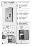
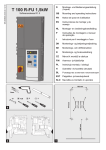
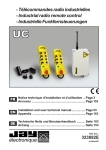
1
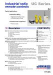
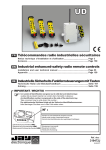
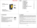
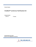
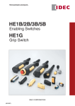
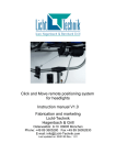
RS Typical applications : Series Industrial equipment : Wireless safety signal transmission from a mobile equipment to a control panel. Supervision of a secure wireless access gate to a dangerous zone. Wireless emergency stop of a conveyor from a forklift truck. Industrial lifting : Wireless safety signal transmission from a machine to a mobile equipment (Travelling cranes, air conveyors,…). Wireless emergency stop from a control to a mobile equipement. 1- Description The system comprises a wireless safety transmitter and a wireless safety receiver. The safety transmitter has the following features : 10 self-controlled function inputs, 1 emergency stop input ensuring a SIL3 safety level. The safety receiver has the following features : 1 radio input associated to the transmitter. 1 two-channel emergency stop input ensuring a SIL3 safety level. 1 EDM input (monitoring of main contactors). 3 safety outputs associated to the transmitter safety input. 6 static outputs associated to the function inputs on the transmitter. 2 static outputs for indication of the operating state. A selection of application programs (manual or automatic receiver restart). To further enhance safety when using this system, innovative technical solutions and options are also proposed : Infrared start-up validation (option) to ensure identication of the machine started up. Choice of operating frequency channel among 64 frequencies in 433-434MHz band. Easy to maintain : Setting and ID code fully stored in a SIM card located in transmitter. Diagnostic aid indicator lights. CONTENTS Para. Page 1- Description ...............................................................p 1 2- Functions of the safety transmitter «RSEF».........p 2 3- Functions of the safety receiver «RSRA».............p 3 4- Product conguration..............................................p 3 5- Technical characteristics.........................................p 4 6- «Startup by IR validation» option ...........................p 5 7- Setting the safety receiver ......................................p 5 8- Typical wiring diagrams ..........................................p 6 9- Product dimensions ................................................p 7 10- Selection guide, references for ordering .............p 8 Compliant with European directives and standards : - Hertzian equipment and telecommunication terminals (low voltage, EM compatibility, radiofrequency spectrum) - Machinery 2006-42 with SIL3 safety level according to EN 61508-1-7 (2001) EN ISO 13849-1 (2008) for the performance level e (Category 4) EC type certicate issued by TÜV Rheinland Functional Safety Type Approved ® TÜV Rheinland FS N°01/205/5190/12 électronique E680 B - 0112 revision01 2- Functions of the safety transmitter «RSEF» Transmitter RSEF Removable connection block, screw terminals 1 2 3 4 7 8 9 10 Green indicator light V1 «Radio transmission» 6 11 12 13 14 Orange indicator light V3 «Power supply» RADIOSAFE RSEF Red indicator light V2 «Error code» 5 V1 V2 V3 BNC plug for BNC antenna extensions and BNC antennas Removable front panel for conguration 15 16 17 18 19 20 21 22 23 24 25 26 27 28 Validation pushbutton (BPV) DIP switch with 8 micro switches for conguration SIM memory card 2 RS Series - Wireless safety logic signal transmission system - E680 B - 0112 revision01 3- Functions of the safety receiver «RSRA» Receiver RSRA S11 S13 Removable connection block, screw terminals White indicator lights V1 and V2 «State of safety receiver» A1+ 48 S12 S14 S21 13 Removable front panel for conguration 23 33 A3+ A2- A5+ 17 27 13 37 IR Red indicator light V3 «Wrong identity code or diagnostic» RADIOSAFE RSRA Green indicator lights K1 and K2 «State of safety relays» S22 S24 S23 V1 V2 K1 K2 V3 14 23 24 33 34 BNC plug for BNC antenna extensions and BNC antennas V4 Green indicator light V4 «Radio reception quality» A2- 58 S32 S34 S42 14 S31 S33 24 34 47 Y1 Y2 57 67 77 A4+ A2- 4- Product conguration All programmings are easily made with a DIP_switch (8 micro-switches) located in front of the transmitter. A simple push on validation button (BPV) can quickly congure and associate the transmitter to the receiver. List of possible congurations: Selection of the transmitter restart mode after a reactivation of its safety input : - «manual» : wiring a restart pushbutton on the transmitter input No. 17. - «automatic» : the transmitter will automatically restart. Frequency channel selection of the transmitter (the receiver will also receive a change order of frequency) : - 64 frequency channels for the standard range transmitter. 25 frequency channels for the extended range transmitter. Conguring the check function for inputs E1 to E10 after reactivation of the safety input : - function «enabled» : the 10 function inputs of the transmitter are checked and must be in NO position. If a problem is detected, the radio emission is not activated and the lights V1 and V2 indicate an error. function «disabled» : state of the inputs is not controlled. E680 B - 0112 revision01 - RS Series - Wireless safety logic signal transmission system 3 5- Technical characteristics 5.1- Safety transmitter RSEF 5.2- Safety receiver RSRA Mechanical characteristics and environmental withstand capacity Mechanical characteristics and environmental withstand capacity Housing material : Plastic Housing material : Plastic Protection index : IP 40 Protection index : IP 40 Weight : 500 g Weight : 500 g Operating temperature range : -20 °C to + 50 °C Operating temperature range : -20 °C to + 50 °C Storage temperature range : - 30 °C to + 70 °C Storage temperature range : - 30 °C to + 70 °C Connection : Screw terminals for wires 0.08² to 2.5² Connection : Screw terminals for wires 0.08² to 2.5² Antenna : 1/4 wave, plug-in on BNC connector, ref : VUB084 Antenna : 1/4 wave, plug-in on BNC connector, ref : VUB084 Electrical characteristics Radio characteristics Power supply voltage : 24 V DC SELV/PELV +/- 20% Radio transmit frequencies : (Interval between adjacent channels : 0,025 MHz) RSEF40 : 64 frequencies, from 433,100 MHz to 434,675 MHz RSEF41 : 25 frequencies, from 434,075 to 434,675 MHz Max. consumption : 120 mA (non-loaded static outputs) Safety relay outputs (K1 and K2) : Contacts : 3 NO forcibly guided contacts Transmit power : <10 mW Tripping time (reaction) : Average range in typical industrial environment (1) : • Active stop time following activation of transmitter safety input : 50 ms RSEF40 : 150 m • Passive stop time : RSEF41 : 250 m - 300 ms for emergency stop according to EN 60204-1, - 1.5 s for a safety stop according EN 60204-32 para 9.2.7, If the requirement of the risk analysis allows it. (2) Electrical characteristics Power supply voltage : 24 V DC SELV/PELV +/- 20% Max. switching voltage. : 250 V AC Switching capacity : Max. consumption : 500 mA • Per AC 15 : AC 3 A / 230 V for NO contacts EN60947-5-1 Number of inputs : 13 • Per DC 13 : DC 8 A / 24 V at 0,1 Hz EN60947-5-1 - 2 safety inputs (emergency stop, safety light barrier etc…) - 10 function inputs Electrical service life : • Per AC15 at 2A, AC230V : 100 000 cycles EN60947-5-1 - 1 «restart» input Static outputs : Low level on input : DC Voltage < 2 V Number and type of outputs : 6 PNP outputs Output voltage : 24 V DC, 100 mA max. High level on input : DC Voltage > 3 V Maximum voltage level on an input with no damage : 30 V Consumption of an input active in the high state : < 20 mA Maximum frequency of a signal on an input : 10 Hz max Indication : 6 indicator lights (2) = In this case, an emergency stop button must be wired on the safety input “S11-S12 and S13-S14” Static outputs : - Number and type of outputs : 2 PNP outputs (images of indicator lights V1 and V2) - Output voltage : 24 V DC, 100 mA max. Indication : 3 indicator lights (1) = Range varies according to environment conditions of transmitter and of receiver antenna (frameworks, metal partitions, etc.). 4 RS Series - Wireless safety logic signal transmission system - E680 B - 0112 revision01 6- «Start-up by IR validation» option If the risk analysis of the application requires it, the start-up zone for an equipment and its identication can be secured by an IR validation on start-up. Functioning principle : Module UDF - To start the equipment (x), the UJF infrared transmitter module connected to the safety transmitter RSEF must be placed in the reception area of the IR receiver module UDF connected to the safety receiver RSRA. UJF IR 10 - Once the validation has been carried out, control commands can be transmitted within the radio range. 30° mm ax. receiver RSRA - The IR start-up function has an action range of 0 to 10 m. Note : The cable used for interconnection between the IR modules and the safety units has a length of 10m. This length can be extended up to 30m (max.) using shielded extensions referenced : UDWR10. Module 60° Moving equipment transmitter ansmitt ttt RSEF Main contactors of equipment (x) NB : This option is only available for receivers RSRA equipped with this functionality. 7- Setting the safety receiver Following application encountered, the receiver restart mode can be programmed. Access to this setup is done by removing the front panel of the receiver : Safety receiver RSRA The receiver has 2 programs which can be congured using the two «B» rotary selector switches. Position of «B» selector switches Receiver restart mode after a Receiver restart mode after a deactivation of the receiver deactivation of the transmitter safety input nb.1 safety input (wired on transmitter (wired on receiver terminals «S11 terminals nb «7 to 10») or loss of to S14») radio link 1 Manual Manual 2 Automatic Automatic E680 B - 0112 revision01 - RS Series - Wireless safety logic signal transmission system Start-up by IR validation YES, possible (If requested by application risk analysis) Remarks Manual restart mode to be privileged Automatic restart mode to be privileged 5 8- Typical wiring diagrams 8.1- Typical wiring diagram for the safety transmitter RSEF Typical wiring diagram with : - 1 emergency stop button connected on the safety input, - 1 «restart» pushbutton, - 10 dry contact inputs (ex. : NO contact pushbutton). 24V DC Emergency stop button Antenna Input nb. 1 Restart PB F1 0,5A T 4 V+ 3 7 8 9 10 V- E.S. 22 17 E.S.2 E.S.1 Mod E.S. V+ E.S. "ON" "Restart" V2 5 6 E1 Input nb. 4 28 E2 Input nb. 5 21 Input nb. 6 27 E3 E4 Input nb. 7 20 E5 26 E6 Input nb. 9 Input nb. 8 19 E7 E8 11 13 12 18 External wiring 24 E9 E10 V- Inputs "Startup by IR validation" option V1 Input nb. 10 25 Safety transmitter RSEF V2 1 Input nb. 3 Input nb.2 14 15 16 23 blue Red indicator light (1) "Transmitter error message" 0V Green indicator light (1) "ON/ Radio transmission active" white External wiring IR Module UJF (1) = External indicator light reflecting transmitter indicator lights V1 and V2 (outputs 11 and 12 : 24VDC, 100mA max.) 8.2- Typical wiring diagram for the safety receiver RSRA Typical wiring diagram with : - 1 «restart» pushbutton, - possibility of implementing an emergency stop button connected to the safety input (a1). - possibility of monitoring main contactor contacts C1 and C2 connected on safety outputs K1 and K2 (a2). This monitoring depends on the safety performance level required by the equipment. 24V DC Antenna Restart PB F2 1A T External wiring A1+ S11 S13 S14 S12 S21 S23 S24 S22 S42 S34 A3 A4 13 23 48 Orange indicator light (1) "Radio reception" (Transmitter RSEF is transmitting) 0V 17 27 37 47 57 67 77 A5+ IR white A2- 14 Emergency stop button 24 34 C1 C2 Green indicator light (1) "Equipment operating" C1 and C2 are main contactors of the equipment blue * Red indicator light (1) "Receiver RSRA error message" (1) = Indicator light of indicator light column (outputs 58, 48 and 14 : 24VDC, 100 mA max.) a1 Y2 K2 "Startup by IR validation" option 58 Y1 K1 Safety receiver RSRA A2- 33 IR Module UDF External wiring * = or brown a2 C1 C2 S11 S13 6 S14 S12 Y1 Y2 RS Series - Wireless safety logic signal transmission system - E680 B - 0112 revision01 8.3- Assignment of inputs connected to transmitter RSEF and static outputs of receiver RSRA Receiver RSRA with «standard» output assignment (ref.: RSRAxSxxx ) Transmitter RSEF inputs E1 Receiver ouput assignment (terminal No.) 27 37 47 57 67 77 Receiver RSRA with «combined» output assignment (ref.: RSRAxCxxx ) Transmitter RSEF inputs X E1 X E2 X X X E4 X E5 X X E3 X E4 X X E2 X E3 Receiver ouput assignment (terminal No.) 27 37 47 57 67 77 E6 X E5 X E6 E7 E7 E8 E8 E9 E9 E10 E10 X X X X X X X X X X 9- Product dimensions Safety transmitter RSEF Safety receiver RSRA Infrared transmitter module UJF Infrared receiver module UDF (for «Start-up by infrared validation» option) 118 Mounting bracket Ø5 84 Ø6 11 67 Plug-in BNC antennas VUB••• 210 unit = mm VUB084 1/4 ~ 335 VUB086 1/2 ~ (Only usable on receiver RSRA) E680 B - 0112 revision01 - RS Series - Wireless safety logic signal transmission system 7 10- Selection guide, references for ordering The RS Series «Wireless safety logic signal transmission system» must be ordered as separate elements : Element Picture Reference Delivered with RSEF40-0 Transmitter with standard range Safety transmitter RSEF41-0 Transmitter with extended range - SIM card (installed) CD (user manual) 90° BNC elbow VUB060 BNC Antenna VUB084 Ant. extension 0,5 m VUB170 RSRA2SA0-0 - 6 «standard» outputs - Passive stop : 0,3 s. RSRA2SB0-0 - 6 «standard» outputs - Passive stop : 1,5 s. RSRA3SB0-0 Safety receiver - 6 «standard» outputs - Passive stop : 1,5 s. - Programmed with «Start-up by infrared validation» option* - 90° BNC elbow VUB060 - BNC Antenna VUB084 - Ant. extension 0,5 m VUB170 RSRA2CB0-0 - 6 «combined» outputs - Passive stop : 1,5 s. * = The infrared transmission module ref.: UJF and the infrared receiver module UDF must be ordered separately Reference Description SIM card RSWF21P Programmed on delivery IR transmission module UJF UJF1 Connection to transmitter RSEF Supplied with 10m cable IR receiver module UDF UDF1 Connection to receiver RSRA Supplied with 10m cable UDWR10 10 m extension cable VUB084 1/4 wave BNC plug VUB086** 1/2 wave BNC plug VUB060 90° BNC elbow VUB170 Length 0,50 m BNC plug (without support) VUB105 Length 2 m BNC plug (with support) (for «Start-up by IR validation» option) (for «Start-up by IR validation» option) Extension cable kit for IR Module UDF Antennas Antenna elbow Antenna extension cables Picture ** = Only usable on receiver RSRA. The products presented in this document are subject to change. Product descriptions and characteristics are not contractually binding. Please go to our internet site www.jay-electronique.fr to download the most recent updates to our documentation. électronique Headofce and plant : ZAC la Bâtie, rue Champrond F38334 SAINT ISMIER cedex Phone :.. +33 (0)4 76 41 44 00 Fax : ...... +33 (0)4 76 41 44 44 Web : ..... www.jay-electronique.fr E680 B - 0112 revision01 Welotec GmbH Distributor Zum Hagenbach 7 D-48366 Laer, GERMANY Tel. +49 (0)2554/9130-00 Fax +49 (0)2554/9130-10 [email protected] www.welotec.com 27.01.2012 - E.D. Accessories