1
xx
ZZZ
MSO3000 and DPO3000 Series
Digital Phosphor Oscilloscopes
Programmer Manual
*P077030100*
077-0301-00
xx
ZZZ
MSO3000 and DPO3000 Series
Digital Phosphor Oscilloscopes
Programmer Manual
www.tektronix.com
077-0301-00
Copyright © Tektronix. All rights reserved. Licensed software products are owned by Tektronix or its subsidiaries
or suppliers, and are protected by national copyright laws and international treaty provisions.
Tektronix products are covered by U.S. and foreign patents, issued and pending. Information in this publication
supersedes that in all previously published material. Specifications and price change privileges reserved.
TEKTRONIX and TEK are registered trademarks of Tektronix, Inc.
Contacting Tektronix
Tektronix, Inc.
14200 SW Karl Braun Drive
P.O. Box 500
Beaverton, OR 97077
USA
For product information, sales, service, and technical support:
In North America, call 1-800-833-9200.
Worldwide, visit www.tektronix.com to find contacts in your area.
Table of Contents
Getting Started ....................................................................................................
Setting Up Remote Communications......................................................................
Command Syntax.................................................................................................
Command and Query Structure ............................................................................
Clearing the oscilloscope ...................................................................................
Command Entry..............................................................................................
Constructed Mnemonics ....................................................................................
Argument Types..............................................................................................
Command Groups ..............................................................................................
Acquisition Command Group ............................................................................
Alias Command Group....................................................................................
Bus Command Group .....................................................................................
Calibration and Diagnostic Command Group ..........................................................
Cursor Command Group ..................................................................................
Display Command Group.................................................................................
Ethernet Command Group ................................................................................
File System Command Group ............................................................................
Hard Copy Command Group .............................................................................
Horizontal Command Group .............................................................................
Mark Command Group....................................................................................
Math Command Group....................................................................................
Measurement Command Group ..........................................................................
Miscellaneous Command Group .........................................................................
PictBridge Command Group .............................................................................
Power Command Group ..................................................................................
Save and Recall Command Group .......................................................................
Search Command Group ..................................................................................
Status and Error Command Group .......................................................................
Trigger Command Group .................................................................................
Vertical Command Group.................................................................................
Waveform Transfer Command Group ...................................................................
Zoom Command Group ...................................................................................
Commands Listed in Alphabetical Order ....................................................................
Status and Events .................................................................................................
Registers ......................................................................................................
Queues ........................................................................................................
Event Handling Sequence...................................................................................
Synchronization Methods ...................................................................................
MSO3000 and DPO3000 Series Programmer Manual
1-1
1-1
2-1
2-1
2-3
2-3
2-5
2-7
2-11
2-11
2-12
2-13
2-16
2-17
2-18
2-19
2-20
2-21
2-23
2-23
2-25
2-26
2-29
2-31
2-31
2-39
2-41
2-46
2-47
2-55
2-59
2-64
2-65
3-1
3-1
3-4
3-5
3-7
i
Table of Contents
Appendix A: Character Set .....................................................................................
Appendix B: Reserved Words ..................................................................................
Appendix C: Programming Example..........................................................................
Index
ii
A-1
B-1
C-1
MSO3000 and DPO3000 Series Programmer Manual
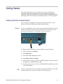
Getting Started
This manual explains the use of commands for remotely controlling your
oscilloscope. With this information, you can write computer programs to
perform functions, such as setting the front-panel controls, taking measurements,
performing statistical calculations, and exporting data for use in other programs.
Setting Up Remote Communications
You can remotely communicate between your oscilloscope and PC via the
Ethernet, USB, and, GPIB using the TEK-USB-488 Adapter.
Ethernet
If you are using Ethernet, start by connecting an appropriate Ethernet cable to the
Ethernet port (RJ-45 connector) on the rear panel of your oscilloscope. This
connects the oscilloscope to a 10/100 Base-T local area network.
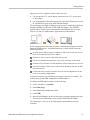
To change the Ethernet settings on your oscilloscope, do the following:
1. On the front panel, push Utility.
2. Push Utility Page.
3. Select I/O with the Multipurpose knob.
4. Push Ethernet Network Settings.
5. On the side-bezel menu, if you are on a DHCP Ethernet network and using a
through cable, set DHCP/BOOTP to On.
6. If you are using a cross-over cable, set DHCP/BOOTP to Off, and set a hard
coded TCPIP address.
USB
If you are using USB, start by connecting an appropriate USB cable to the USB
2.0 high-speed device port on the rear panel of your oscilloscope.
MSO3000 and DPO3000 Series Programmer Manual
1-1
Getting Started
With USB, the system automatically configures itself. To verify that the USB is
enabled:
1. On the front panel, push Utility.
2. Push Utility Page.
3. Select I/O with the Multipurpose knob.
4. Push USB, and verify that USB is enabled.
5. If USB is disabled, push Connect to computer on the side-bezel menu.
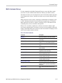
After connection, the host, with appropriate software, can list the oscilloscope as a
USB device with the following parameters. (See Table 1-1.)
Table 1-1: USB Device Parameters
GPIB
1-2
Parameter
Value
Manufacturer ID
0x0699 (decimal 1689)
Product ID
0x0410 (decimal 1040) DPO3012
0x0411 (decimal 1041) DPO3014
0x0412 (decimal 1042) DPO3032
0x0413 (decimal 1043) DPO3034
0x0414 (decimal 1044) DPO3052
0x0415 (decimal 1045) DPO3054
Serial number
Serial number
Manufacturer description
“Tektronix”
Interface description
“USBTMC-USB488”
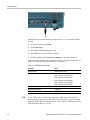
To use GPIB, start by connecting an appropriate USB cable to the USB 2.0
high-speed device port on the rear panel of your oscilloscope. Connect the other
end to the TEK-USB-488 Adapter host port. Then connect a GPIB cable from the
TEK-USB-488 Adapter to your PC.
MSO3000 and DPO3000 Series Programmer Manual
Getting Started
Supply power to the Adapter in either of these two ways:
1. Use the optional 5 VDC power adapter connected to the 5 VDC power input
on the Adapter.
2. Use an appropriate USB cable connected to a powered USB host port on your
PC and the Device port on the TEK-USB-488 Adapter.
The oscilloscope has a USB 2.0 high-speed device port to control the oscilloscope
through USBTMC or GPIB with a TEK-USB-488 Adapter. The USBTMC
protocol allows USB devices to communicate using IEEE488 style messages.
This lets you run your GPIB software applications on USB hardware.
Before setting up the oscilloscope for remote communication using the electronic
(physical) GPIB interface, you should familiarize yourself with the following
GPIB requirements:
A unique device address must be assigned to each device on the bus. No two
devices can share the same device address.
No than 15 devices can be connected to any one line.
One device should be connected for every 6 feet (2 meters) of cable used.
No than 65 feet (20 meters) of cable should be used to connect devices to a bus.
At least two-thirds of the devices on the network should be powered on while
using the network.
Connect the devices on the network in a star or linear configuration. Do not
use loop or parallel configurations.
To function correctly, your oscilloscope must have a unique device address. The
default setting for the GPIB configuration is GPIB Address 1.
To change the GPIB address settings, do the following:
1. On the front panel, push Utility.
2. Push Utility Page.
3. Select I/O with the Multipurpose knob.
4. Push GPIB.
5. Enter the GPIB address on the side-bezel menu, using the multipurpose knob.
This will set the GPIB address on an attached TEK-USB-488 Adapter.
The oscilloscope is now set up for bidirectional communication with your
controller.
MSO3000 and DPO3000 Series Programmer Manual
1-3
Getting Started
Documentation
The following documents are available for download on the Manuals Finder
Web site at www.tektronix.com:
MSO3000 and DPO3000 Series User Manual. Information about installing
and operating the oscilloscope.
Getting Started with OpenChoice ™ Solutions Manual. Options for getting data
from your oscilloscope into any one of several available analysis tools.
MSO3000 and DPO3000 Series Technical Reference. Oscilloscope specifications
and a performance verification procedure.
TekVISA Programmer Manual. Description of TekVISA, the Tektronix
implementation of the VISA Application Programming Interface (API). TekVISA
is industry-compliant software for writing interoperable oscilloscope drivers in a
variety of Application Development Environments (ADEs).
1-4
MSO3000 and DPO3000 Series Programmer Manual
Command Syntax
You can control the operations and functions of the oscilloscope through the
Ethernet port or the USB 2.0 device port using commands and queries. The
related topics listed below describe the syntax of these commands and queries.
The topics also describe the conventions that the oscilloscope uses to process
them. See the Command Groups topic in the table of contents for a listing of the
commands by command group, or use the index to locate a specific command.
Backus-Naur Form
Notation
This documentation describes the commands and queries using Backus-Naur
Form (BNF) notation. Refer to the following table for the symbols that are used.
Table 2-1: Symbols for Backus-Naur Form
Symbol
<>
Meaning
=
Is defined as
|
Exclusive OR
Defined element
{}
Group; one element is required
[]
.. .
Optional; can be omitted
()
Comment
Previous element(s) may be repeated
Command and Query Structure
Commands consist of set commands and query commands (usually called
commands and queries). Commands modify oscilloscope settings or tell the
oscilloscope to perform a specific action. Queries cause the oscilloscope to return
data and status information.
Most commands have both a set form and a query form. The query form of the
command differs from the set form by its question mark at the end. For example,
the set command ACQuire:MODe has a query form ACQuire:MODe?. Not all
commands have both a set and a query form. Some commands have set only and
some have query only.
Messages
A command message is a command or query name followed by any information
the oscilloscope needs to execute the command or query. Command messages
may contain five element types, defined in the following table.
MSO3000 and DPO3000 Series Programmer Manual
2-1
Command Syntax
Table 2-2: Command Message Elements
Commands
Symbol
Meaning
<Header>
This is the basic command name. If the header ends with a question
mark, the command is a query. The header may begin with a colon
(:) character. If the command is concatenated with other commands,
the beginning colon is required. Never use the beginning colon with
command headers beginning with a star (*).
<Mnemonic>
This is a header subfunction. Some command headers have only one
mnemonic. If a command header has multiple mnemonics, a colon (:)
character always separates them from each other.
<Argument>
This is a quantity, quality, restriction, or limit associated with the header.
Some commands have no arguments while others have multiple
arguments. A <space> separates arguments from the header. A
<comma> separates arguments from each other.
<Comma>
A single comma is used between arguments of multiple-argument
commands. Optionally, there may be white space characters before
and after the comma.
<Space>
A white space character is used between a command header and the
related argument. Optionally, a white space may consist of multiple
white space characters.
Commands cause the oscilloscope to perform a specific function or change one of
the settings. Commands have the structure:
[:]<Header>[<Space><Argument>[<Comma> <Argument>]...]
A command header consists of one or more mnemonics arranged in a hierarchical
or tree structure. The first mnemonic is the base or root of the tree and each
subsequent mnemonic is a level or branch off the previous one. Commands at a
higher level in the tree may affect those at a lower level. The leading colon (:)
always returns you to the base of the command tree.
2-2
MSO3000 and DPO3000 Series Programmer Manual
Command Syntax
Queries
Queries cause the oscilloscope to return status or setting information. Queries
have the structure:
[:]<Header>
[:]<Header>[<Space><Argument> [<Comma><Argument>]...]
You can specify a query command at any level within the command tree unless
otherwise noted. These branch queries return information about all the mnemonics
below the specified branch or level.
Headers
Use the HEADer command to control whether the oscilloscope returns headers as
part of the query response. If header is on, the query response returns command
headers, then formats itself as a valid set command. When header is off, the
response includes only the values. This may make it easier to parse and extract the
information from the response. The table below shows the difference in responses.
Table 2-3: Comparison of Header Off and Header On Responses
Query
Header Off
Header On
TIME?
14:30:00
:TIME “14:30:00”
ACQuire:NUMAVg?
100
:ACQUIRE:NUMAVG 100
Clearing the oscilloscope
You can clear the Output Queue and reset the oscilloscope to accept a new
command or query by using the selected Device Clear (DCL) function.
Command Entry
The following rules apply when entering commands:
You can enter commands in upper or lower case.
You can precede any command with white space characters. White space
characters include any combination of the ASCII control characters 00 through
09 and 0B through 20 hexadecimal (0 through 9 and 11 through 32 decimal).
The oscilloscope ignores commands consisting of any combination of white
space characters and line feeds.
MSO3000 and DPO3000 Series Programmer Manual
2-3
Command Syntax
Abbreviating
You can abbreviate many oscilloscope commands. Each command in this
documentation shows the minimum acceptable abbreviations in capitals. For
example, you can enter the command ACQuire:NUMAvg simply as ACQ:NUMA
or acq:numa.
Abbreviation rules may change over time as new oscilloscope models are
introduced. Thus, for the most robust code, use the full spelling.
If you use the HEADer command to have command headers included as part
of query responses, you can further control whether the returned headers are
abbreviated or are full-length with the VERBose command.
Concatenating
You can concatenate any combination of set commands and queries using a
semicolon (;). The oscilloscope executes concatenated commands in the order
received.
When concatenating commands and queries, you must follow these rules:
1. Separate completely different headers by a semicolon and by the beginning
colon on all commands except the first one. For example, the commands
TRIGger:MODe NORMal and ACQuire:NUMAVg 8, can be concatenated
into the following single command:
TRIGger:MODe NORMal;:ACQuire:NUMAVg 8
2. If concatenated commands have headers that differ by only the last mnemonic,
you can abbreviate the second command and eliminate the beginning colon.
For example, you can concatenate the commands ACQuire:MODe ENVelope
and ACQuire:NUMAVg 8 into a single command:
ACQuire:MODe ENVelope; NUMAVg 8
The longer version works equally well:
ACQuire:MODe ENVelope;:ACQuire:NUMAVg 8
3. Never precede a star (*) command with a colon:
ACQuire:STATE 1;*OPC
Any commands that follow will be processed as if the star command was
not there so the commands, ACQuire:MODe ENVelope;*OPC;NUMAVg 8
will set the acquisition mode to envelope and set the number of acquisitions
for averaging to 8.
4. When you concatenate queries, the responses to all the queries are
concatenated into a single response message. For example, if the display
graticule is set to Full and the display style is set to dotsonly, the concatenated
query DISplay:GRAticule?;STYle:DOTsonly? will return the following.
If the header is on:
DISPLAY:GRATICULE FULL;:DISPLAY:STYLE:DOTSONLY 1
2-4
MSO3000 and DPO3000 Series Programmer Manual
Command Syntax
If the header is off:
FULL;1
5. Set commands and queries may be concatenated in the same message. For
example,
ACQuire:MODe SAMple;NUMAVg?;STATE?
is a valid message that sets the acquisition mode to sample. The message then
queries the number of acquisitions for averaging and the acquisition state.
Concatenated commands and queries are executed in the order received.
Here are some invalid concatenations:
DISPlay:STYle:NORMal;ACQuire:NUMAVg 8 (no colon before ACQuire)
DISPlay:GRAticule FULL;:DOTSONLY OFF (extra colon before
DOTSonly. You could use DISPlay:DOTsonly OFF instead)
DISPlay:GRAticule FULL;:*TRG (colon before a star (*) command)
MATH:HORizontal:SCAle 1.0e-1;HORizontal:POSition 5.0el
(levels of the mnemonics are different; either remove the second use of
HORizontal: or place :MATH in front of HORizontal:POSition)
Terminating
This documentation uses <EOM> (End of Message) to represent a message
terminator.
Table 2-4: End of Message Terminator
Symbol
Meaning
<EOM>
Message terminator
The end-of-message terminator must be the END message (EOI asserted
concurrently with the last data byte). The last data byte may be an ASCII line
feed (LF) character.
This oscilloscope does not support ASCII LF only message termination. The
oscilloscope always terminates outgoing messages with LF and EOI.
Constructed Mnemonics
Some header mnemonics specify one of a range of mnemonics. For example, a
channel mnemonic can be CH1, CH2, CH3, or CH4. You use these mnemonics
in the command just as you do any other mnemonic. For example, there is a
CH1:POSition command, and there is also a CH2:POSition command. In the
command descriptions, this list of choices is abbreviated as CH<x>.
MSO3000 and DPO3000 Series Programmer Manual
2-5
Command Syntax
Cursor Position
Mnemonics
When cursors are displayed, commands may specify which cursor of the pair to
use.
Table 2-5: Channel Mnemonics
Symbol
Meaning
CH<x>
A channel specifier; <x> is 1 through 4.
Table 2-6: Cursor Mnemonics
Math Specifier Mnemonics
Symbol
Meaning
CURSOR<x>
A cursor selector; <x> is either 1 or 2.
POSITION<x>
A cursor selector; <x> is either 1 or 2.
HPOS<x>
A cursor selector; <x> is either 1 or 2.
Commands can specify the mathematical waveform to use as a mnemonic in
the header.
Table 2-7: Math Specifier Mnemonics
Measurement Specifier
Mnemonics
Symbol
Meaning
Math<x>
A math waveform specifier; <x> is 1.
Commands can specify which measurement to set or query as a mnemonic in the
header. Up to four automated measurements may be displayed.
Table 2-8: Measurement Specifier Mnemonics
Symbol
Meaning
MEAS<x>
A measurement specifier; <x> is 1 through 4.
Channel Mnemonics
Commands specify the channel to use as a mnemonic in the header.
Reference Waveform
Mnemonics
Commands can specify the reference waveform to use as a mnemonic in the
header.
Table 2-9: Reference Waveform Mnemonics
2-6
Symbol
Meaning
REF<x>
A reference waveform specifier; <x> is 1, 2, 3, or 4 for 4-channel
oscilloscopes and 1 or 2 for 2-channel oscilloscopes.
MSO3000 and DPO3000 Series Programmer Manual
Command Syntax
Argument Types
Commands use arguments such as enumeration, numeric, quoted string and block.
Each of these arguments are listed in detail below.
Enumeration
Enter these arguments as unquoted text words. Like key words, enumeration
arguments follow the same convention where the portion indicated in uppercase is
required and that in lowercase is optional.
For example: SAVe:WAVEform:FILEFormat INTERNal
Numeric
Many oscilloscope commands require numeric arguments. The syntax shows
the format that the oscilloscope returns in response to a query. This is also the
preferred format when sending the command to the oscilloscope though any of
the formats will be accepted. This documentation represents these arguments as
described below.
Table 2-10: Numeric Arguments
Symbol
Meaning
<NR1>
Signed integer value
<NR2>
Floating point value without an exponent
<NR3>
Floating point value with an exponent
<bin>
Digital data in binary format
Most numeric arguments will be automatically forced to a valid setting, by either
rounding or truncating, when an invalid number is input, unless otherwise noted
in the command description.
Quoted String
Some commands accept or return data in the form of a quoted string, which is
simply a group of ASCII characters enclosed by a single quote (’) or double quote
("). The following is an example of a quoted string: "This is a quoted
string". This documentation represents these arguments as follows:
Table 2-11: Quoted String Argument
Symbol
Meaning
<QString>
Quoted string of ASCII text
MSO3000 and DPO3000 Series Programmer Manual
2-7
Command Syntax
A quoted string can include any character defined in the 7-bit ASCII character
set. Follow these rules when you use quoted strings:
1. Use the same type of quote character to open and close the string. For
example: "this is a valid string".
2. You can mix quotation marks within a string as long as you follow the
previous rule. For example: "this is an ’acceptable’ string".
3. You can include a quote character within a string by repeating the quote. For
example: "here is a "" mark".
4. Strings can have upper or lower case characters.
5. If you use a GPIB network, you cannot terminate a quoted string with the
END message before the closing delimiter.
6. A carriage return or line feed embedded in a quoted string does not terminate
the string. The return is treated as another character in the string.
7. The maximum length of a quoted string returned from a query is 1000
characters.
Here are some invalid strings:
"Invalid string argument’ (quotes are not of the same type)
"test<EOI>" (termination character is embedded in the string)
Block
Several oscilloscope commands use a block argument form, as defined in the
table below.
Table 2-12: Block Argument
Symbol
Meaning
<NZDig>
A nonzero digit character in the range of 1–9
<Dig>
A digit character, in the range of 0–9
<DChar>
A character with the hexadecimal equivalent of 00 through FF (0
through 255 decimal)
<Block>
A block of data bytes defined as: <Block> ::=
{#<NZDig><Dig>[<Dig>...][<DChar>...] |#0[<DChar>...]<terminator>}
<NZDig> specifies the number of <Dig> elements that follow. Taken together,
the <NZDig> and <Dig> elements form a decimal integer that specifies how
many <DChar> elements follow.
2-8
MSO3000 and DPO3000 Series Programmer Manual
Command Syntax
MSO3000 and DPO3000 Series Programmer Manual
2-9
Command Syntax
2-10
MSO3000 and DPO3000 Series Programmer Manual
Command Groups
This manual lists the DPO3000 Series IEEE488.2 commands in two ways. First,
it presents them by functional groups. Then, it lists them alphabetically. The
functional group list starts below. The alphabetical list provides detail on each
command. (See page 2-65, Commands Listed in Alphabetical Order.)
Acquisition Command Group
Use the commands in the Acquisition Command Group to set up the modes and
functions that control how the oscilloscope acquires signals input to the channels,
and processes them into waveforms.
Using the commands in this group, you can do the following:
Start and stop acquisitions.
Control whether each waveform is simply acquired, averaged, or enveloped
over successive acquisitions of that waveform.
Set the controls or conditions that start and stop acquisitions.
Control acquisition of channel waveforms.
Set acquisition parameters.
Table 2-13: Acquisition Commands
Command
Description
ACQuire?
Returns the acquisition parameters
ACQuire:MAGnivu
Sets or returns the MagniVu feature
ACQuire:MAXSamplerate?
Returns the maximum real-time sample rate
ACQuire:MODe
Sets or returns the acquisition mode
ACQuire:NUMACq?
Returns the number of acquisitions that have
occurred
ACQuire:NUMAVg
Sets or returns the number of acquisitions for
an averaged waveform
ACQuire:STATE
Starts or stops the acquisition system
ACQuire:STOPAfter
Sets or returns whether the acquisition is
continuous or single sequence
MSO3000 and DPO3000 Series Programmer Manual
2-11
Command Groups
Alias Command Group
Use the Alias commands to define new commands as a sequence of standard
commands. You may find this useful when repeatedly using the same commands
to perform certain tasks like setting up measurements.
Aliases are similar to macros but do not include the capability to substitute
parameters into alias bodies. The alias mechanism obeys the following rules:
The alias name must consist of a valid IEEE488.2 message unit, which may
not appear in a message preceded by a colon, comma, or a command or query
program header.
The alias name may not appear in a message followed by a colon, comma,
or question mark.
An alias name must be distinct from any keyword or keyword short form.
An alias name cannot be redefined without first being deleted using one of
the alias deletion functions.
Alias names do not appear in response messages.
Table 2-14: Alias Commands
2-12
Command
Description
ALIas
Sets or returns the alias state
ALIas:CATalog?
Returns a list of the currently defined alias
labels
ALIas:DEFine
Assigns a sequence of program messages
to an alias label
ALIas:DELEte
Removes a specified alias
ALIas:DELEte:ALL
Deletes all existing aliases
ALIas:DELEte[:NAMe]
Removes a specified alias
ALIas[:STATE]
Sets or returns the alias state
MSO3000 and DPO3000 Series Programmer Manual
Command Groups
Bus Command Group
Use the Bus commands when working with serial or parallel bus measurements.
Install the DPO3EMBD application module when working with I2C or SPI
bus signals.
Install the DPO3AUTO module when working with CAN or LIN bus signals.
Install the DPO3COMP module when working with RS-232, RS-422,
RS-485, and UART bus signals.
Install the DPO3AUDIO module when working with I2S, Left Justified (LJ),
Right Justified (RJ), and TDM bus signals.
NOTE. The parallel bus commands work with MSO3000 Series oscilloscopes only.
NOTE. The Search Command Group and the Trigger Command Group also
contain bus-related commands.
Table 2-15: Bus Commands
Commands
Description
BUS
Returns the parameters for each bus
BUS:B<x>:AUDio:BITDelay
Sets or returns the number of delay bits for
the AUDIO bus
BUS:B<x>:AUDio:BITOrder
Sets or returns the bit order for the AUDIO
bus
BUS:B<x>:AUDio:CHANnel:SIZe
Sets or returns the number of bits per
channel for the AUDIO bus
BUS:B<x>:AUDio:CLOCk:POLarity
Sets or returns the clock polarity for the
AUDIO bus
BUS:B<x>:AUDio:CLOCk:SOUrce
Sets or returns the clock source waveform
for the AUDIO bus
BUS:B<x>:AUDio:DATa:POLarity
Sets or returns the data polarity for the
AUDIO bus
BUS:B<x>:AUDio:DATa:SIZe
Sets or returns the number of bits per word
for the AUDIO bus
BUS:B<x>:AUDio:DATa:SOUrce
Sets or returns the data source waveform for
the AUDIO bus
BUS:B<x>:AUDio:DISplay:FORMat
Sets or returns the display format for the
AUDIO bus
BUS:B<x>:AUDio:FRAME:SIZe
Sets or returns the number of channels in
each frame for the AUDIO bus
BUS:B<x>:AUDio:FRAMESync:POLarity
Sets or returns the frame sync polarity for
the AUDIO bus
MSO3000 and DPO3000 Series Programmer Manual
2-13
Command Groups
Table 2-15: Bus Commands (cont.)
2-14
Commands
Description
BUS:B<x>:AUDio:FRAMESync:SOUrce
Sets or returns the frame sync source
waveform for the AUDIO bus
BUS:B<x>:AUDio:TYPe
Sets or returns the audio format (type) for
the AUDIO bus
BUS:B<x>:AUDio:WORDSel:POLarity
Sets or returns the word select polarity for
the AUDIO bus
BUS:B<x>:AUDio:WORDSel:SOUrce
Sets or returns the word select source
waveform for the AUDIO bus
BUS:B<x>:CAN:BITRate
Sets or returns the bit rate for the CAN bus
BUS:B<x>:CAN:PRObe
Sets or returns the probing method used to
probe the CAN bus
BUS:B<x>:CAN:SAMPLEpoint
Sets or returns the sample point (in %) to
sample during each bit period
BUS:B<x>:CAN:SOUrce
Sets or returns the CAN data source
BUS:B<x>:DISplay:FORMAt
Sets the display format for the numerical
information in the specified bus waveform
BUS:B<x>:DISplay:TYPe
Sets the display type for the specified bus
BUS:B<x>:I2C:ADDRess:RWINClude
Sets and returns whether the read/write bit is
included in the address
BUS:B<x>:I2C{:CLOCK|:SCLK}:SOUrce
Sets or returns the I2C SCLK source
BUS:B<x>:I2C{:DATA|:SDATA}:SOUrce
Sets or returns the I2C SDATA source
BUS:B<x>:LABel
Sets or returns the waveform label for the
specified bus
BUS:B<x>:LIN:BITRate
Sets or returns the bit rate for LIN
BUS:B<x>:LIN:IDFORmat
Sets or returns the LIN ID format
BUS:B<x>:LIN:POLARity
Sets or returns the LIN polarity
BUS:B<x>:LIN:SAMPLEpoint
Sets or returns the sample point (in %) at
which to sample during each bit period
BUS:B<x>:LIN:SOUrce
Sets or returns the LIN data source
BUS:B<x>:LIN:STANDard
Sets or returns the LIN standard
BUS:B<x>:PARallel:BIT<x>:SOUrce
Sets or returns the parallel bit source for the
specified bus
BUS:B<x>:PARallel:CLOCK:EDGE
Sets or returns the parallel clock edge for the
specified bus
BUS:B<x>:PARallel:CLOCK:ISCLOCKed
Sets or returns the parallel bus clock function
for the specified bus
BUS:B<x>:PARallel:CLOCK:SOUrce
Sets or returns the parallel clock source for
the specified bus
BUS:B<x>:PARallel:WIDth
Sets or returns the width of the parallel bus
MSO3000 and DPO3000 Series Programmer Manual
Command Groups
Table 2-15: Bus Commands (cont.)
Commands
Description
BUS:B<x>:POSition
Sets or returns the position of the specified
bus waveform
BUS:B<x>:RS232C:BITRate
Sets or returns the RS-232 bit rate for the
specified bus
BUS:B<x>:RS232C:DATABits
Sets or returns the number of bits for the
data frame
BUS:B<x>:RS232C:DELIMiter
Sets or returns the RS-232 delimiting value
for a packet on the specified bus
BUS:B<x>:RS232C:DISplaymode
Sets or returns the display mode for the
specified bus display and event table
BUS:B<x>:RS232C:PARity
Sets or returns the parity for RS-232 data
BUS:B<x>:RS232C:POLarity
Sets or returns the RS-232C polarity for the
specified bus
BUS:B<x>:RS232C:RX:SOUrce
Sets or returns the RS-232 RX source
BUS:B<x>:RS232C:TX:SOUrce
Sets or returns the RS-232 TX Source
BUS:B<x>:SPI{:CLOCK|:SCLK}:POLARity
Sets or returns the SPI SCLK polarity
BUS:B<x>:SPI{:CLOCK|:SCLK}:SOUrce
Sets or returns the SPI SCLK source
BUS:B<x>:SPI:DATA{:IN|:MISO}:POLARity
Sets or returns the SPI MISO polarity
BUS:B<x>:SPI:DATA{:IN|:MISO}:SOUrce
Sets or returns the SPI MISO source
BUS:B<x>:SPI:DATA{:OUT|:MOSI}:
POLARity
Sets or returns the SPI MOSI polarity
BUS:B<x>:SPI:DATA{:OUT|:MOSI}:SOUrce
Sets or returns the SPI MOSI source
BUS:B<x>:SPI{:SELect|:SS}:POLARity
Sets or returns the SPI SS polarity
BUS:B<x>:SPI{:SELect|:SS}:SOUrce
Sets or returns the SPI SS source
BUS:B<x>SPI:FRAMing
Sets or returns the type of SPI framing
BUS:B<x>:STATE
Turns the specified bus on and off
BUS:B<x>:TYPE
Sets or returns the specified bus type
BUS:LOWerthreshold:CH<x>
Sets or returns the lower threshold for each
channel
BUS:THReshold:D<x>
Sets or returns the threshold for a digital
channel
BUS:UPPerthreshold:CH<x>
Sets or returns the upper threshold for each
channel
MSO3000 and DPO3000 Series Programmer Manual
2-15
Command Groups
Calibration and Diagnostic Command Group
The Calibration and Diagnostic commands provide information about the current
state of oscilloscope calibration. They also initiate internal signal path calibration
(SPC) or execute diagnostic tests. Commands that are specific to factory
calibration are not described in this manual. They are described in the Service
manual, located on the DPO3000 Documentation CD-ROM in PDF format. You
can also order a printed copy.
Table 2-16: Calibration and Diagnostic Commands
2-16
Command
Description
*CAL?
Instructs the oscilloscope to perform
self-calibration and returns the oscilloscope
self calibration status
CALibrate:FACtory:STATus?
Returns the factory calibration status value
saved in nonvolatile memory
CALibrate:INTERNal
Starts a signal path compensation
CALibrate:INTERNal:STARt
Starts the internal signal path calibration
CALibrate:INTERNal:STATus?
Returns the current status of the internal
signal path calibration
CALibrate:RESults?
Returns the status of all calibration
subsystems without performing an SPC
operation
CALibrate:RESults:FACtory?
Returns the status of internal and factory
calibration
CALibrate:RESults:SPC?
Returns the results of the last SPC operation
DIAg:LOOP:OPTion
Sets the self-test loop option
DIAg:LOOP:OPTion:NTIMes
Sets the self-test loop option to run N times
DIAg:LOOP:STOP
Stops the self-test at the end of the current
loop
DIAg:RESUlt:FLAg?
Returns the pass/fail status from the last
self-test sequence execution
DIAg:RESUlt:LOG?
Returns the internal results log from the last
self-test sequence execution
DIAg:SELect:<function>
Selects one of the available self-test areas
DIAg:STATE
Sets the oscilloscope operating state
DIAg:SELect
Sets the type of diagnostics grouping
MSO3000 and DPO3000 Series Programmer Manual
Command Groups
Cursor Command Group
Use the commands in the Cursor Command Group to control the cursor display
and readout. You can use these commands to control the setups for cursor 1 and
cursor 2, such as cursor position.
You can also use the commands to select one of the following cursor functions:
Off. Turns off the display of all cursors.
Waveform Cursors. Consists of two cursors. Waveform cursors enable you to
conveniently measure waveform amplitude and time.
Screen Cursors. Consists of two pairs of independent horizontal and vertical
cursors. You can use these cursors to indicate an arbitrary position within
the waveform display area.
Table 2-17: Cursor Commands
Command
Description
CURSor?
Returns the cursor settings
CURSor:DDT?
Returns the cursor deltaY/deltaT (dY/dT)
readout
CURSor:FUNCtion
Sets or returns the cursor type
CURSor:HBArs?
Returns the hbar cursor settings
CURSor:HBArs:DELTa?
Returns the hbars cursors vertical difference
CURSor:HBArs:POSITION<x>
Sets or returns the hbar cursor<x> vertical
position
CURSor:HBArs:UNIts
Returns the hbar cursor units
CURSor:HBArs:USE
Sets the horizontal bar cursor measurement
scale, for use with ratio cursors
CURSor:MODe
Sets or returns whether cursors move in
unison or separately
CURSor:VBArs?
Sets or returns the position of vertical bar
cursors
CURSor:VBArs:ALTERNATE<x>?
Returns the alternate readout for the
waveform (Vbar) cursors
CURSor:VBArs:DELTa?
Returns the horizontal difference between
vbar cursors
CURSor:VBArs:HPOS<x>?
Returns the vertical value of the specified
vertical bar tick
CURSor:VBArs:POSITION<x>
Sets or returns the vbar cursor<x> horizontal
position
CURSor:VBArs:UNIts
Sets or returns the horizontal units for vbar
cursors
CURSor:VBArs:USE
Sets the vertical bar cursor measurement
scale
MSO3000 and DPO3000 Series Programmer Manual
2-17
Command Groups
Table 2-17: Cursor Commands (cont.)
Command
Description
CURSor:VBArs:VDELTa?
Returns the vertical difference between the
two vertical bar cursor ticks
CURSor:XY:POLar:RADIUS:DELta?
Returns the difference between the cursors
X radius and the cursor Y radius
CURSor:XY:POLar:RADIUS:POSITION<x>?
Returns the polar radius of the specified
cursor
CURSor:XY:POLar:RADIUS:UNIts?
Returns the polar radius units
CURSor:XY:POLar:THETA:DELta?
Returns the XY cursor polar coordinate delta
CURSor:XY:POLar:THETA:POSITION<x>?
Returns the cursor X or cursor Y polar
coordinate
CURSor:XY:POLar:THETA:UNIts?
Returns the cursor polar coordinate units
CURSor:XY:PRODUCT:DELta?
Returns the difference between the cursors
X position and cursor Y position
CURSor:XY:PRODUCT:POSITION<x>?
Returns the position of the X or Y cursor used
to calculate the X × Y cursor measurement
CURSor:XY:PRODUCT:UNIts?
Returns the XY cursor product units
CURSor:XY:RATIO:DELta?
Returns the ratio of the difference between
the cursor X position and cursor Y position
CURSor:XY:RATIO:POSITION<x>?
Returns the X or Y position for the specified
cursor
CURSor:XY:RATIO:UNIts?
Returns the X and Y cursor units for the ratio
measurement
CURSor:XY:READOUT
Sets or returns the XY cursor readout
selection
CURSor:XY:RECTangular:X:DELta?
Returns the X delta value in rectangular
coordinates
CURSor:XY:RECTangular:X:POSITION<x>
Sets or returns the cursor X rectangular
coordinates
CURSor:XY:RECTangular:X:UNIts?
Returns the cursor X rectangular units
CURSor:XY:RECTangular:Y:DELta?
Returns the cursor Y delta value in
rectangular coordinates
CURSor:XY:RECTangular:Y:POSITION<x>>
Sets or returns the cursor Y rectangular
coordinate
CURSor:XY:RECTangular:Y:UNIts?
Returns the cursor Y rectangular units
Display Command Group
Use the commands in the Display Command Group to change the graticule style,
the display intensities, and to set the characteristics of the waveform display.
Also, use it to send messages to the display.
2-18
MSO3000 and DPO3000 Series Programmer Manual
Command Groups
NOTE. Your settings globally affect all displayed waveforms.
Table 2-18: Display Commands
Command
Description
DISplay?
Returns the current display settings
DISplay:CLOCk
Sets or returns the display of the date/time
stamp
DISplay:DIGital:HEIght
Sets or returns the number of available digital
waveform position slots
DISplay:GRAticule
Sets or returns the type of graticule that is
displayed
DISplay:FORMat
Sets or returns the display format
DISplay:INTENSITy?
Returns all the display intensity settings
DISplay:INTENSITy:BACKLight
Sets or returns the backlight intensity for the
display
DISplay:INTENSITy:GRAticule
Sets or returns the graticule intensity for the
display
DISplay:INTENSITy:WAVEform
Sets or returns the intensity of the waveforms
DISplay:PERSistence
Sets or returns the display persistence
setting
DISplay:STYle:DOTsonly
Sets a dots-only display
MESSage
Sets or queries message box (screen
annotation) parameters
MESSage:BOX
Sets or returns the coordinates of the
message box
MESSage:CLEAR
Clears the contents of the message box
MESSage:SHOW
Sets or returns the contents of the message
box
MESSage:STATE
Controls the display of the message box
Ethernet Command Group
Use the commands in the Ethernet Command Group to set up the Ethernet remote
interface.
Table 2-19: Ethernet Commands
Command
Description
ETHERnet:DHCPbootp
Sets or returns the network initialization
search for a DHCP/BOOTP server
ETHERnet:DNS:IPADDress
Sets or returns the network Domain Name
Server (Dns) IP address
MSO3000 and DPO3000 Series Programmer Manual
2-19
Command Groups
Table 2-19: Ethernet Commands (cont.)
Command
Description
ETHERnet:DOMAINname
Sets or returns the network domain name
ETHERnet:ENET:ADDress?
Returns the Ethernet address value assigned
to the oscilloscope
ETHERnet:GATEWay:IPADDress
Sets or returns the remote interface gateway
IP address
ETHERnet:HTTPPort
Sets or returns the remote interface HTTP
port value
ETHERnet:IPADDress
Sets or returns the IP address assigned to
the oscilloscope
ETHERnet:NAME
Sets or returns the network name assigned
to the oscilloscope
ETHERnet:PASSWord
Sets or returns the Ethernet access password
ETHERnet:PING
Causes the oscilloscope to ping the gateway
IP address
ETHERnet:PING:STATUS?
Returns the results from pinging the gateway
IP address
ETHERnet:SUBNETMask
Sets or returns the remote interface subnet
mask value
File System Command Group
Use the commands in the File System Command Group to help you use USB
media. You can use the commands to do the following:
List the contents of a directory
Create and delete directories
Create, read, rename, or delete a file
Format media
When using these commands, keep the following points in mind:
File arguments are always enclosed within double quotes:
"E:/MYDIR/TEK00001.SET"
File names follow the non-case sensitive, MSDOS format:
[DRIVE:][\PATH\]filename
Path separators may be either forward slashes (/) or back slashes (\)
2-20
MSO3000 and DPO3000 Series Programmer Manual
Command Groups
NOTE. Using back slash as a path separator may produce some unexpected
results, depending on how your application treats escaped characters. Many
applications recognize the sequence of back slash followed by an alphabetic
character as an escaped character, and, as such, interpret that alphabetic
character as a control character. For example, the sequence "\n" may be
interpreted as a newline character; "\t" may be interpreted as a tab character. To
ensure that this interpretation does not occur, you can use double back slashes.
For example, "E:\\testfile.txt".
Table 2-20: File System Commands
Command
Description
FILESystem?
Returns the directory listing of the current
working directory and the number of bytes of
free space available
FILESystem:CWD
Sets or returns the current working directory
for FILESystem commands
FILESystem:DELEte
Deletes a named file or directory
FILESystem:DIR?
Returns a list of directory contents
FILESystem:FORMat
Formats a named drive
FILESystem:FREESpace?
Returns the number of bytes of free space
on the current drive
FILESystem:MKDir
Creates a new directory
FILESystem:READFile
Writes the contents of the specified file to the
specified interface
FILESystem:REName
Assigns a new name to an existing file
FILESystem:RMDir
Deletes a named directory
FILESystem:WRITEFile
Writes the specified block data to the
oscilloscope current working directory
Hard Copy Command Group
Use the commands in the Hard Copy Command Group to make hard copies.
PictBridge commands belong to a separate group. (See page 2-31, PictBridge
Command Group.)
Table 2-21: Hard Copy Commands
Command
Description
HARDCopy
Sends a copy of the screen display to the
selected printer
HARDCopy:ACTIVeprinter
Sets or returns the currently active printer
HARDCopy:INKSaver
Changes hard copy output to print color
traces and graticule on a white background
MSO3000 and DPO3000 Series Programmer Manual
2-21
Command Groups
Table 2-21: Hard Copy Commands (cont.)
2-22
Command
Description
HARDCopy:LAYout
Sets or returns the page orientation for hard
copy
HARDCopy:PREVIEW
Previews the current screen contents with
the InkSaver palette applied
HARDCopy:PRINTer:ADD
Adds a network printer to the list of available
printers
HARDCopy:PRINTer:DELete
Removes a network printer from the list of
available printers
HARDCopy:PRINTer:LIST?
Returns the list of currently attached printers
HARDCopy:PRINTer:REName
Renames a network printer in the list of
available printers
MSO3000 and DPO3000 Series Programmer Manual
Command Groups
Horizontal Command Group
Use the commands in the Horizontal Command Group to control the oscilloscope
horizontal parameters.
Table 2-22: Horizontal Commands
Command
Description
HORizontal?
Returns settings for the horizontal commands
HORizontal:DELay:MODe
Sets or returns the horizontal delay mode
HORizontal:DELay:TIMe
Sets or returns the horizontal delay time
(position) that is used when delay is on
HORizontal:DIGital:RECOrdlength:
MAGnivu?
Returns the record length of the MagniVu
digital acquisition
HORizontal:DIGital:RECOrdlength:MAIN?
Returns the record length of the main digital
acquisition
HORizontal:DIGital:SAMPLERate:
MAGnivu?
Returns the sample rate of the Magnivu
digital acquisition
HORizontal:DIGital:SAMPLERate:MAIN?
Returns the sample rate of the main digital
acquisition
HORizontal:POSition
Sets or returns the horizontal position, in
percent, that is used when delay is off
HORizontal:PREViewstate?
Returns the display system preview state
HORizontal:RECOrdlength
Sets or returns the record length
HORizontal:SAMPLERate
Sets or returns the sample rate
HORizontal:SCAle
Sets or returns the horizontal scale
HORizontal:DIGital:RECOrdlength:
MAGnivu?
Returns the record length of the MagniVu
digital acquisition
HORizontal:DIGital:RECOrdlength:MAIN?
Returns the record length of the main digital
acquisition
HORizontal:DIGital:SAMPLERate:
MAGnivu?
Returns the sample rate of the Magnivu
digital acquisition
HORizontal:DIGital:SAMPLERate:MAIN?
Returns the sample rate of the main digital
acquisition
Mark Command Group
Use the commands in the Mark Command Group to identify areas of the acquired
waveform that warrant further investigation.
MSO3000 and DPO3000 Series Programmer Manual
2-23
Command Groups
Table 2-23: Mark Commands
2-24
Command
Description
MARK
Moves to the next or previous reference
mark on the waveform. Returns the current
mark position
MARK:CREATE
Creates a mark on a particular waveform or
all waveforms in a column
MARK:DELEte
Deletes a mark on a particular waveform, all
waveforms in a column, or all marks
MARK:FREE?
Returns how many marks are free to be used
MARK:SELected:END?
Returns the end of the selected mark, in
terms of 0 to 100% of the waveform
MARK:SELected:FOCUS?
Returns the focus of the selected mark, in
terms of 0 to 100% of the waveform
MARK:SELected:MARKSINCOLumn?
Returns how many marks are in the current
zoom pixel column
MARK:SELected:OWNer?
Returns the owner of the selected mark
MARK:SELected:SOURCE?
Returns the source waveform of the selected
mark
MARK:SELected:STARt?
Returns the start of the selected mark, in
terms of 0 to 100% of the waveform
MARK:SELected:STATe?
Returns the on or off state of the selected
mark
MARK:SELected:ZOOm:POSition?
Returns the position of the selected mark, in
terms of 0 to 100% of the upper window
MARK:TOTal?
Returns how many marks are used
MSO3000 and DPO3000 Series Programmer Manual
Command Groups
Math Command Group
Use the commands in the Math Command Group to create and define a math
waveform. Use the available math functions to define your math waveform.
The math waveform you create depends on sources listed in the math expression.
If you change these sources, the math waveform you previously defined will be
affected.
Math expressions can be simple, containing no mathematical computation, such
as CH1, which specifies that a waveform shows the signal source of Channel 1.
Math expressions can also be complex, consisting of up to 128 characters and
comprising many sources, functions, and operands.
When a live waveform is updated or a reference waveform is altered, math
waveforms containing those waveforms as sources are also updated to reflect the
changes. Remember that sources must exist, but do not need to be displayed, to be
used in and to update math waveforms.
Table 2-24: Math Commands
Command
Description
MATH[1]?
Returns the definition of the math waveform
MATH[1]:DEFine
Sets or returns the current math function as
a text string
MATH[1]:HORizontal:SCAle
Sets or returns the math horizontal display
scale for FFT or for Dual Math waveforms
MATH[1]:HORizontal:UNIts
Returns the math waveform horizontal unit
value
{MATH|MATH1}:LABel
Sets or queries the waveform label for the
math waveform
MATH[1]:SPECTral:MAG
Sets or returns the units of spectral
magnification in the math string
MATH[1]:SPECTral:WINdow
Sets or returns the window function for math
waveform spectral input data
MATH[1]:VERTical:POSition
Sets or returns the vertical position of the
currently selected math type
MATH[1]:VERTical:SCAle
Sets or returns the vertical scale of the
currently selected math type
MATH[1]:VERTical:UNIts
Returns the math waveform vertical units
MATH[1]:HORizontal:POSition
Sets or returns the math horizontal display
position for FFT or (non-live) math reference
waveforms
MATH[1]:TYPe
Sets or returns the math waveform mode
type
MSO3000 and DPO3000 Series Programmer Manual
2-25
Command Groups
Table 2-24: Math Commands (cont.)
Command
Description
MATHVAR?
Returns all numerical values used within
math expressions
MATHVAR:VAR<x>
Sets or returns numerical values you can use
within math expressions
Measurement Command Group
Use the commands in the Measurement Command Group to control the automated
measurement system.
Up to four automated measurements can be displayed on the screen. In the
commands, these measurement readouts are named MEAS<x>, where <x> is the
measurement number.
In addition to the four displayed measurements, the measurement commands let
you specify an additional measurement, IMMed. The immediate measurement
has no front-panel equivalent. Immediate measurements are never displayed.
Because they are computed only when needed, immediate measurements slow the
waveform update rate less than displayed measurements.
Whether you use displayed or immediate measurements, use the VALue query to
obtain measurement results.
Measurement commands can set and query measurement parameters. You
can assign some parameters, such as waveform sources, differently for each
measurement. Other parameters, such as reference levels, have only one value,
which applies to all measurements.
Table 2-25: Measurement Commands
2-26
Command
Description
MEASUrement?
Returns all measurement parameters
MEASUrement:CLEARSNapshot
Removes the measurement snapshot display
MEASUrement:GATing
Sets or returns the measurement gating
MEASUrement:IMMed?
Returns all immediate measurement setup
parameters
MEASUrement:IMMed:DELay?
Returns information about the immediate
delay measurement
MEASUrement:IMMed:DELay:DIRection
Sets or returns the search direction to use for
immediate delay measurements
MEASUrement:IMMed:DELay:EDGE<x>
Sets or returns the slope of the edge used for
immediate delay “from” and “to” waveform
measurements
MSO3000 and DPO3000 Series Programmer Manual
Command Groups
Table 2-25: Measurement Commands (cont.)
Command
Description
MEASUrement:IMMed:SOUrce<x>
Sets or returns the source for the current
single channel measurement
MEASUrement:IMMed:SOUrce1
Sets or returns the “from” source for all single
channel immediate measurements
MEASUrement:IMMed:SOUrce2
Sets or returns the source to measure “to” for
phase or delay immediate measurements
MEASUrement:IMMed:TYPe
Sets or returns the type of the immediate
measurement
MEASUrement:IMMed:UNIts?
Returns the units of the immediate
measurement
MEASUrement:IMMed:VALue?
Returns the value of the immediate
measurement
MEASUrement:INDICators?
Returns all measurement indicator
parameters
MEASUrement:INDICators:HORZ<x>?
Returns the position of the specified
horizontal measurement indicator
MEASUrement:INDICators:NUMHORZ?
Returns the number of horizontal
measurement indicators currently being
displayed
MEASUrement:INDICators:NUMVERT?
Returns the number of vertical measurement
indicators currently being displayed
MEASUrement:INDICators:STATE
Sets or returns the state of visible
measurement indicators
MEASUrement:INDICators:VERT<x>?
Returns the value of the specified vertical
measurement indicator
MEASUrement:MEAS<x>?
Returns all measurement parameters
MEASUrement:MEAS<x>:COUNt?
Returns the number of values accumulated
since the last statistical reset
MEASUrement:MEAS<x>:DELay?
Returns the delay measurement parameters
for the specified measurement
MEASUrement:MEAS<x>:DELay:DIRection
Sets or returns the search direction to use for
delay measurements
MEASUrement:MEAS<x>:DELay:EDGE<x>
Sets or returns the slope of the edge to
use for delay “from” and “to” waveform
measurements
MEASUrement:MEAS<x>:MAXimum?
Returns the maximum value found since the
last statistical reset
MEASUrement:MEAS<x>:MEAN?
Returns the mean value accumulated since
the last statistical reset
MEASUrement:MEAS<x>:MINImum?
Returns the minimum value found since the
last statistical reset
MSO3000 and DPO3000 Series Programmer Manual
2-27
Command Groups
Table 2-25: Measurement Commands (cont.)
2-28
Command
Description
MEASUrement:MEAS<x>:SOUrce<x>
Sets or returns the source for the specified
measurement
MEASUrement:MEAS<x>:SOURCE[1]
Sets or returns the channel from which
measurements are taken
MEASUrement:MEAS<x>:SOURCE2
Sets or returns the channel to which
measurements are sent
MEASUrement:MEAS<x>:STATE
Sets or returns whether the specified
measurement slot is computed and
displayed
MEASUrement:MEAS<x>:STDdev?
Returns the standard deviation of values
accumulated since the last statistical reset
MEASUrement:MEAS<x>:TYPe
Sets or returns the measurement<x> type
MEASUrement:MEAS<x>:UNIts?
Returns measurement<x> units
MEASUrement:MEAS<x>:VALue?
Returns the value of measurement<x>
MEASUrement:METHod
Sets or returns the method used for
calculating reference levels
MEASUrement:REFLevel?
Returns the current reference level
parameters
MEASUrement:REFLevel:ABSolute:HIGH
Sets or returns the top reference level for
rise and fall time
MEASUrement:REFLevel:ABSolute:LOW
Sets or returns the low reference level for
rise and fall time
MEASUrement:REFLevel:ABSolute:MID
Sets or returns the mid reference level for
measurements
MEASUrement:REFLevel:ABSolute:MID<x>
Sets or returns the mid reference level in
absolute units (e.g. volts)
MEASUrement:REFLevel:ABSolute:MID2
Sets or returns the mid reference level for
delay "to" measurements
MEASUrement:REFLevel:METHod
Specifies or returns the reference level units
used for measurement calculations
MEASUrement:REFLevel:PERCent:HIGH
Sets or returns the top reference percent
level for rise and fall time
MEASUrement:REFLevel:PERCent:LOW
Sets or returns the low reference percent
level for rise and fall time
MEASUrement:REFLevel:PERCent:MID
Sets or returns the mid reference percent
level for waveform measurements
MEASUrement:REFLevel:PERCent:MID<x>
Sets or returns the mid reference level for
the specified channel in percent
MEASUrement:REFLevel:PERCent:MID2
Sets or returns the mid reference percent
level for second waveform measurements
MEASUrement:SNAPShot
Displays the measurement snapshot list
MSO3000 and DPO3000 Series Programmer Manual
Command Groups
Table 2-25: Measurement Commands (cont.)
Command
Description
MEASUrement:STATIstics:MODE
Turns measurement statistics on or off
MEASUrement:STATIstics
Clears or returns all of the statistics
accumulated for all period measurements
(MEAS1 through MEAS4)
MEASUrement:STATIstics:WEIghting
Controls the responsiveness of the mean
and standard deviation to waveform changes
Miscellaneous Command Group
Use the commands in the Miscellaneous Command Group to perform actions that
do not fit into other categories.
Several commands and queries are common to all 488.2-1987 devices. The
488.2-1987 standard defines these commands. The common commands begin
with an asterisk (*) character.
Table 2-26: Miscellaneous Commands
Command
Description
AUTOSet
Sets the vertical, horizontal, and trigger
controls of the oscilloscope to automatically
acquire and display the appropriate
waveform(s). This is equivalent to pressing
the front panel Autoset button
AUTOSet:ENAble
Enables or disables the autoset feature
CLEARMenu
Clears the current menu from the display
DATE
Sets or returns the date displayed by the
oscilloscope
*DDT
Sets or returns the commands that will be
executed by the group execute trigger
FPAnel:PRESS
Simulates the action of pressing a specified
front-panel button
FPAnel:TURN
Duplicates the action of turning a specified
front-panel control knob
GPIBUsb:ADDress?
Returns the current GPIB address
GPIBUsb:ID?
Returns the identification string of the
connected adaptor module and firmware
version
HEADer
Sets or returns the Response Header Enable
State
ID?
Returns identifying information about the
oscilloscope and its firmware
MSO3000 and DPO3000 Series Programmer Manual
2-29
Command Groups
Table 2-26: Miscellaneous Commands (cont.)
2-30
Command
Description
*IDN?
Returns the same information as the ID?
command except the data is formatted
according to Tektronix Codes & Formats
LANGuage
Sets or returns the user interface display
language
LOCk
Sets or returns the front panel lock state
*LRN?
Returns a listing of oscilloscope settings
MESSage
Sets or queries message parameters
NEWpass
Changes the password for user protected
data
PASSWord
Enables the *PUD and NEWpass set
commands
REM
Specifies a comment, which is ignored by
the oscilloscope
SET?
Returns a listing of oscilloscope settings
TEKSecure
Initializes both waveform and setup
memories
TIME
Sets or returns the time displayed by the
oscilloscope
TOTaluptime?
Returns the total number of hours that the
oscilloscope has been turned on since the
nonvolatile memory was last programmed
*TRG
Performs the group execute trigger (GET)
*TST?
Tests the interface and returns the status
UNLock
Unlocks front panel
USBTMC?
Returns the USBTMC information used by
the USB hosts to determine the instrument
interfaces
USBTMC:PRODUCTID:DECimal?
Returns the product ID of the USBTMC
device in decimal format
USBTMC:PRODUCTID:HEXadecimal?
Returns the product ID of the USBTMC
device in hexadecimal format
USBTMC:SERIALnumber?
Returns the serial number of the USBTMC
device
USBTMC:VENDORID:DECimal?
Returns the vendor ID of the USBTMC
device in decimal format
USBTMC:VENDORID:HEXadecimal?
Returns the vendor ID of the USBTMC
device in hexadecimal format
VERBose
Sets or returns the verbose state
MSO3000 and DPO3000 Series Programmer Manual
Command Groups
PictBridge Command Group
Use the commands in the PictBridge Command Group to store printer settings.
Table 2-27: PictBridge Commands
Command
Description
PICTBridge:DATEPrint
Enables or disables printing the date on the
print output
PICTBridge:DEFault
Sets the arguments for all PICTBridge
commands to their default values
PICTBridge:IDPrint
Enables or disables printing the oscilloscope
model and serial number on the print output
PICTBridge:IMAGESize
Sets or returns the image print size
PICTBridge:PAPERSize
Sets the output print paper size
PICTBridge:PAPERType
Sets or returns the paper type
PICTBridge:PRINTQual
Sets or returns the output print quality
USBDevice:CONFigure
Enables or disables the rear USB port for
use with Pictbridge printers
Power Command Group
Use the commands in the Power Command Group for power analysis. The power
measurements include:
Power quality
Switching loss
Safe operating area
Harmonics
Ripple
Modulation analysis
This command group is available when the DPO3PWR application module is
installed.
Table 2-28: Power Commands
Command
Description
POWer:CURRENTSOurce
Sets or returns the current source for the
power application
POWer:DISplay
Sets or returns the display state for the
power application
POWer:GATESOurce
Sets or returns the gate source for the power
application
MSO3000 and DPO3000 Series Programmer Manual
2-31
Command Groups
Table 2-28: Power Commands (cont.)
2-32
Command
Description
POWer:GATing
Sets or returns the power application gating
POWer:HARMonics:DISPlay:SELect
Sets or returns the harmonics to be displayed
when the harmonics standard is None
POWer:HARMonics:DISPlay:TYPe
Sets or returns the display type for harmonics
tests
POWer:HARMonics:FREQRef
Sets or returns the frequency reference
waveform for harmonics tests
POWer:HARMonics:FREQRef:
FIXEDFREQValue
Sets or returns the fixed reference frequency
value for harmonics measurements
POWer:HARMonics:IEC:CLAss
Sets or returns the filtering class for IEC
harmonics
POWer:HARMonics:IEC:FILter
Sets or returns the enabled state for filtering
of IEC harmonics
POWer:HARMonics:IEC:FUNDamental
Sets or returns the fundamental current for
IEC harmonics
POWer:HARMonics:IEC:GROUPing
Sets or returns the enabled state for grouping
of IEC harmonics
POWer:HARMonics:IEC:INPUTPOWer
Sets of returns the class D input power for
IEC harmonics
POWer:HARMonics:IEC:LINEFREQuency
Sets or returns the line frequency for the IEC
standard
POWer:HARMonics:IEC:OBSPERiod
Sets or returns the IEC observation period
POWer:HARMonics:IEC:POWERFACtor
Sets or returns the power factor for IEC
harmonics
POWer:HARMonics:MIL:FUNDamental:
CALCmethod
Sets or returns the measurement method for
the MIL harmonics fundamental frequency
POWer:HARMonics:MIL:FUNDamental:
USER:CURRent
Sets or returns RMS amperes for User
calculation method
POWer:HARMonics:MIL:LINEFREQuency
Sets or returns the line frequency for
MIL-STD-1399 harmonics tests
POWer:HARMonics:MIL:POWERLEVel
Sets or returns the power level for
MIL-STD-1399 harmonics tests
POWer:HARMonics:NR_HARMonics
Sets of returns the number of harmonics (a
value in the range of 20 to 400) when the
harmonics standard is NONe
POWer:HARMonics:RESults:HAR<1-400>:
FREQuency?
Returns the frequency of the harmonic
MSO3000 and DPO3000 Series Programmer Manual
Command Groups
Table 2-28: Power Commands (cont.)
Command
Description
POWer:HARMonics:RESults:HAR<1-400>:
IECMAX?
The IEC standard specifies harmonics
measurements to be computed in windows of
time, with each time window being nominally
200 ms. This returns the maximum of the
RMS magnitude of the harmonic, computed
across successive 200 ms time windows
within an observation period entered by the
user
POWer:HARMonics:RESults:HAR<1-400>:
LIMit?
The IEC and MIL standards specify a limit for
each harmonic magnitude. Returns the limit
in absolute units, or as a percentage of the
fundamental as specified by the standard.
IEC Class C (Table 2) and MIL standards
specify the limit as a percentage of the
fundamental
POWer:HARMonics:RESults:HAR<1-400>:
PHASe?
Returns the phase of the harmonic in
degrees. The phase is measured relative to
the zero-crossing of the reference waveform.
When there is no reference waveform,
the phase is relative to the fundamental
component
POWer:HARMonics:RESults:HAR<1-400>:
RMS:ABSolute?
Returns the RMS magnitude of the harmonic
expressed in absolute units
POWer:HARMonics:RESults:HAR<1-400>:
RMS:PERCent?
Returns the RMS magnitude of the
harmonic expressed as a percentage of the
fundamental
POWer:HARMonics:RESults:HAR<1-400>:
TEST:IEC:CLASSALIMit?
Returns PASS, FAIL or NA. Specifies if
the IEC Class A higher harmonic limit (and
conditions) are met
POWer:HARMonics:RESults:HAR<1-400>:
TEST:IEC:NORMAL?
Returns PASS, FAIL or NA. Specifies if the
Normal IEC harmonic limits are met
POWer:HARMonics:RESults:HAR<1-400>:
TEST:IEC:POHCLIMit?
Returns PASS, FAIL or NA. Specifies if the
higher harmonic limit (and conditions) for the
21st and higher order odd harmonics are met
POWer:HARMonics:RESults:HAR<1-400>:
TEST:MIL:NORMAL?
Returns the test result for the specified
harmonic for the MIL-STD-1399 testing
standard
POWer:HARMonics:RESults:IEC:
FUNDamental?
Returns the IEC fundamental frequency
POWer:HARMonics:RESults:IEC:
HARM3ALTernate?
Returns the IEC harmonics test result for the
3rd harmonic: PASS, FAIL or NA
POWer:HARMonics:RESults:IEC:
HARM5ALTernate?
Returns the IEC harmonics test result for the
5th harmonic: PASS, FAIL or NA
POWer:HARMonics:RESults:IEC:POHC?
Returns the IEC POHC measurement
MSO3000 and DPO3000 Series Programmer Manual
2-33
Command Groups
Table 2-28: Power Commands (cont.)
2-34
Command
Description
POWer:HARMonics:RESults:IEC:POHL?
Returns the IEC POHL measurement
POWer:HARMonics:RESults:IEC:POWer?
Returns the IEC input power measurement
POWer:HARMonics:RESults:IEC:
POWERFactor?
Returns the IEC power factor measurement
POWer:HARMonics:RESults:PASSFail?
Returns the overall harmonics test result:
PASS, FAIL or NA
POWer:HARMonics:RESults:RMS?
Returns the root mean square value of the
source waveform
POWer:HARMonics:RESults:SAVe
Saves the harmonic results to the specified
file in CSV format
POWer:HARMonics:RESults:THDF?
Returns the Total Harmonic Distortion (THD)
in percentage, measured as a ratio to the
RMS value of the fundamental component of
the source waveform
POWer:HARMonics:RESults:THDR?
Returns the Total Harmonic Distortion (THD)
in percentage, measured as a ratio to the
RMS value of the source waveform
POWer:HARMonics:SOURce
Sets or returns the source waveform for
harmonics tests
POWer:HARMonics:STANDard
Sets or returns the standard for harmonics
tests
POWer:INDICators
Sets or returns the state of the measurement
indicators for the power application
POWer:MODulation:SOUrce
Sets or returns the source waveform for
modulation tests
POWer:MODulation:TYPe
Sets or returns the modulation type
POWer:QUALity:APPpwr?
Returns the apparent power measurement
POWer:QUALity:DISplay:APPpwr
Sets or returns the display state for the
apparent power readout
POWer:QUALity:DISplay:FREQuency
Sets or returns the display state for the
frequency readout
POWer:QUALity:DISplay:ICRESTfactor
Sets or returns the display state for the
current crest factor readout
POWer:QUALity:DISplay:IRMS
Sets or returns the display state for the RMS
current (IRMS) readout
POWer:QUALity:DISplay:PHASEangle
Sets or returns the display state for the
phase angle readout
POWer:QUALity:DISplay:POWERFACtor
Sets or returns the display state for the
power factor readout
POWer:QUALity:DISplay:REACTpwr
Sets or returns the display state for the
reactive power readout
MSO3000 and DPO3000 Series Programmer Manual
Command Groups
Table 2-28: Power Commands (cont.)
Command
Description
POWer:QUALity:DISplay:TRUEpwr
Sets or returns the display state for the true
power readout
POWer:QUALity:DISplay:VCRESTfactor
Sets or returns the display state for the
voltage crest factor readout
POWer:QUALity:DISplay:VRMS
Sets or returns the display state for the RMS
voltage (VRMS) readout
POWer:QUALity:FREQREFerence
Sets or returns the power quality frequency
reference
POWer:QUALity:FREQuency?
Returns the frequency measurement
POWer:QUALity:ICRESTfactor?
Returns the current crest factor measurement
POWer:QUALity:IRMS?
Returns the RMS current measurement
POWer:QUALity:PHASEangle?
Returns the phase angle measurement
POWer:QUALity:POWERFACtor?
Returns the power factor measurement
POWer:QUALity:REACTpwr?
Returns the reactive power measurement
POWer:QUALity:TRUEpwr?
Returns the true power measurement
POWer:QUALity:VRMS?
Returns the RMS voltage measurement
POWer:REFLevel:ABSolute
Sets the reference levels to their default unit
values
POWer:REFLevel:ABSolute:HIGH
Sets or returns the top reference level for
rise time
POWer:REFLevel:ABSolute:LOW
Sets or returns the low reference level for
rise time
POWer:REFLevel:ABSolute:MID<1-3>
Sets or returns the mid reference level for
measurements
POWer:REFLevel:HYSTeresis
Sets or returns the measurement reference
level hysteresis value
POWer:REFLevel:METHod
Sets or returns the method used to calculate
the 0% and 100% reference level
POWer:REFLevel:PERCent
Sets the reference levels to the default
percentage values
POWer:REFLevel:PERCent:HIGH
Sets or returns the top reference percent
level for rise time
POWer:REFLevel:PERCent:LOW
Sets or returns the low reference percent
level for rise time
POWer:REFLevel:PERCent:MID<1-3>
Sets or returns the mid reference percent
level for waveform measurements
POWer:RIPPle
Sets the vertical offset of the source
waveform
POWer:RIPPle:RESults:AMPLitude?
Returns the peak-to-peak ripple
measurement
MSO3000 and DPO3000 Series Programmer Manual
2-35
Command Groups
Table 2-28: Power Commands (cont.)
2-36
Command
Description
POWer:RIPPle:RESults:MAX?
Returns the maximum of the peak-to-peak
ripple measurements
POWer:RIPPle:RESults:MEAN?
Returns the mean of the peak-to-peak ripple
measurements
POWer:RIPPle:RESults:MIN?
Returns the minimum of the peak-to-peak
ripple measurement
POWer:RIPPle:RESults:STDdev?
Returns the standard deviation of the
peak-to-peak ripple measurements
POWer:RIPPle:SOUrce
Sets or returns the source waveform for
ripple tests
POWer:SOA:LINear:XMAX
Sets or returns the user XMAX value for use
in linear SOA calculations
POWer:SOA:LINear:XMIN
Sets or returns the user XMIN value for use
in linear SOA calculations
POWer:SOA:LINear:YMAX
Sets or returns the user YMAX value for use
in linear SOA calculations
POWer:SOA:LINear:YMIN
Sets or returns the user YMIN value for use
in linear SOA calculations
POWer:SOA:LOG:XMAX
Sets or returns the user XMAX value for use
in log SOA calculations
POWer:SOA:LOG:XMIN
Sets or returns the user XMIN value for use
in log SOA calculations
POWer:SOA:LOG:YMAX
Sets or returns the user YMAX value for use
in log SOA calculations
POWer:SOA:LOG:YMIN
Sets or returns the user YMIN value for use
in log SOA calculations
POWer:SOA:MASK:DEFine
Sets or returns the X (Volts) and Y (Amps)
coordinates of the current SOA mask
POWer:SOA:MASK:MAXAmps
Sets or returns the maximum current applied
to SOA mask testing
POWer:SOA:MASK:MAXVolts
Sets or returns the maximum voltage applied
to SOA mask testing
POWer:SOA:MASK:MAXWatts
Sets or returns the maximum power applied
to SOA mask testing
POWer:SOA:MASK:NR_PT?
Returns the number of mask points defined
POWer:SOA:MASK:STATe
Sets or returns the state of the mask for SOA
calculations
POWer:SOA:MASK:STOPOnviol
Sets or returns the enabled state of the mask
stop on violation condition
POWer:SOA:PLOTTYPe
Sets or returns the SOA plot type
POWer:SOA:RESult:FAILures:QTY?
Returns the number of failures in the test
MSO3000 and DPO3000 Series Programmer Manual
Command Groups
Table 2-28: Power Commands (cont.)
Command
Description
POWer:SOA:RESult:NUMACq?
Returns the number of acquisitions in the test
POWer:SOA:RESult:STATe?
Returns the pass/fail state of the SOA test
POWer:STATIstics
Clears all the accumulated statistics of all
measurements
POWer:STATIstics:MODE
Enables or disables the display of the
measurement statistics
POWer:STATIstics:WEIghting
Sets the number of samples which are
included for the statistics computations for
mean and the standard deviation
POWer:SWLoss:CONDCALCmethod
Sets or returns the power application
switching loss conduction calculation method
POWer:SWLoss:CONDuction:ENERGY:
MAX?
Returns the maximum conduction energy for
the switching loss calculation
POWer:SWLoss:CONDuction:ENERGY:
MEAN?
Returns the mean conduction energy for the
switching loss calculation
POWer:SWLoss:CONDuction:ENERGY:
MIN?
Returns the minimum conduction energy for
the switching loss calculation
POWer:SWLoss:CONDuction:POWER:
MAX?
Returns the maximum conduction power for
the switching loss calculation
POWer:SWLoss:CONDuction:POWER:
MEAN?
Returns the mean conduction power for the
switching loss calculation
POWer:SWLoss:CONDuction:POWER:
MIN?
Returns the minimum conduction power for
the switching loss calculation
POWer:SWLoss:DISplay
Sets or returns the display selection for
switching loss results
POWer:SWLoss:GATe:POLarity
Sets or returns the switching loss gate
polarity
POWer:SWLoss:GATe:TURNON
Sets or returns the gate turn on level for
switching loss power measurements
POWer:SWLoss:NUMCYCles?
Returns the number of cycles counted for the
switching loss calculation
POWer:SWLoss:RDSon
Sets or returns RDSON value for use
in switching loss calculations when the
conduction calculation method is RDSON
POWer:SWLoss:REFLevel:ABSolute:
GATEMid
Sets or returns the mid voltage reference
level used in switching loss power
measurements in volts
POWer:SWLoss:REFLevel:ABSolute:
LOWCurrent
Sets or returns the low current reference level
used in switching loss power measurements
in amperes
MSO3000 and DPO3000 Series Programmer Manual
2-37
Command Groups
Table 2-28: Power Commands (cont.)
2-38
Command
Description
POWer:SWLoss:REFLevel:ABSolute:
LOWVoltage
Sets or returns the low voltage reference level
used in switching loss power measurements
in volts
POWer:SWLoss:REFLevel:PERCent:
GATEMid
Sets or returns the mid voltage reference
level used in switching loss power
measurements in percentage
POWer:SWLoss:REFLevel:PERCent:
LOWCurrent
Sets or returns the low current reference level
used in switching loss power measurements
in percentage
POWer:SWLoss:REFLevel:PERCent:
LOWVoltage
Sets or returns the low voltage reference level
used in switching loss power measurements
in percentage
POWer:SWLoss:TOFF:ENERGY:MAX?
Returns the maximum Toff energy for the
switching loss calculation
POWer:SWLoss:TOFF:ENERGY:MEAN?
Returns the mean Toff energy for the
switching loss calculation
POWer:SWLoss:TOFF:ENERGY:MIN?
Returns the minimum Toff energy for the
switching loss calculation
POWer:SWLoss:TOFF:POWER:MAX?
Returns the number of maximum Toff power
switching loss calculation
POWer:SWLoss:TOFF:POWER:MEAN?
Returns the mean Toff power for the
switching loss calculation
POWer:SWLoss:TOFF:POWER:MIN?
Returns the minimum Toff power for the
switching loss calculation
POWer:SWLoss:TON:ENERGY:MAX?
Returns the maximum Ton energy for the
switching loss calculation
POWer:SWLoss:TON:ENERGY:MEAN?
Returns the mean Ton energy for the
switching loss calculation
POWer:SWLoss:TON:ENERGY:MIN?
Returns the minimum Ton energy for the
switching loss calculation
POWer:SWLoss:TON:POWER:MAX?
Returns the maximum Ton power for the
switching loss calculation
POWer:SWLoss:TON:POWER:MEAN?
Returns the mean Ton power for the
switching loss calculation
POWer:SWLoss:TON:POWER:MIN?
Returns the minimum Ton power for the
switching loss calculation
POWer:SWLoss:TOTal:ENERGY:MAX?
Returns the maximum total energy for the
switching loss calculation
POWer:SWLoss:TOTal:ENERGY:MEAN?
Returns the mean total energy for the
switching loss calculation
POWer:SWLoss:TOTal:ENERGY:MIN?
Returns the minimum total energy for the
switching loss calculation
MSO3000 and DPO3000 Series Programmer Manual
Command Groups
Table 2-28: Power Commands (cont.)
Command
Description
POWer:SWLoss:TOTal:POWER:MAX?
Returns the maximum total power for the
switching loss calculation
POWer:SWLoss:TOTal:POWER:MEAN?
Returns the mean total power for the
switching loss calculation
POWer:SWLoss:TOTal:POWER:MIN?
Returns the minimum total power for the
switching loss calculation
POWer:SWLoss:VCEsat
Sets or returns VCESAT value for use
in switching loss calculations when the
conduction calculation method is VCESAT
POWer:TYPe
Sets or returns the power application
measurement type
POWer:VOLTAGESOurce
Sets or returns the voltage source for the
power application
Save and Recall Command Group
Use the commands in the Save and Recall Command Group to store and retrieve
waveforms and settings. When you save a setup, you save all the settings of the
oscilloscope. When you recall a setup, the oscilloscope restores itself to the state
it was in when you originally saved the setting.
Table 2-29: Save and Recall Commands
Command
Description
FACtory
Resets the oscilloscope to factory default
settings
*RCL
Recalls saved oscilloscope settings
RECAll:SETUp
Recalls saved oscilloscope settings
RECAll:WAVEform
Recalls a stored waveform to a reference
location
*SAV
Stores the state of the oscilloscope to a
specified memory location
SAVe:ASSIgn:TYPe
Sets or returns the assignment of the Save
button
SAVe:EVENTtable:BUS<x>
Saves event table data from bus<x> to a
specified file
SAVe:IMAGe
Saves a capture of the screen image to the
specified file
MSO3000 and DPO3000 Series Programmer Manual
2-39
Command Groups
Table 2-29: Save and Recall Commands (cont.)
2-40
Command
Description
SAVe:IMAGe:FILEFormat
Sets or returns the file format to use for
saving screen images. The file format is not
automatically determined by the file name
extension. You need to choose a file name
with an extension which is consistent with
the selected file format
SAVe:IMAGe:INKSaver
Sets or returns the current inksaver setting
for the SAVe:IMAGe command
SAVe:IMAGe:LAYout
Sets or returns the layout to use for saved
screen images
SAVe:SETUp
Saves the state of the oscilloscope to a
specified memory location or file
SAVe:WAVEform
Saves a waveform to one of the reference
memory locations or a file
SAVe:WAVEform:FILEFormat
Sets or returns the format for saved
waveforms
SAVe:WAVEform:GATIng
Specifies whether save waveform operations
should save the entire waveform or a
specified portion of the waveform
SETUP<x>:DATE?
Returns the date when the specified
oscilloscope setup was saved
SETUP<x>:LABEL
Sets or returns the specified oscilloscope
setup label
SETUP<x>:TIME?
Returns the time when the specified
oscilloscope setup was saved
MSO3000 and DPO3000 Series Programmer Manual
Command Groups
Search Command Group
Use the commands in the Search Commands Group to seek out information in
waveform records.
Search Commands
Command
Description
SEARCH?
Returns all search-related settings
SEARCH:SEARCH<x>:COPy
Copies the search criteria to the trigger, or
the trigger criteria to the search.
SEARCH:SEARCH<x>:STATE
Sets the search state to on or off
SEARCH:SEARCH<x>:TOTAL?
Returns the total number of matches for
search <x>
SEARCH:SEARCH<x>:TRIGger:A:BUS?
Returns the search trigger bus type
SEARCH:SEARCH<x>:TRIGger:A:BUS:
B<x>:AUDio:CONDition
Sets or returns the search trigger condition
for the AUDIO bus: Start of Frame or Data
SEARCH:SEARCH<x>:TRIGger:A:BUS:
B<x>:AUDio:DATa:HIVALue
Sets or returns the search trigger data upper
word for the AUDIO bus
SEARCH:SEARCH<x>:TRIGger:A:BUS:
B<x>:AUDio:DATa:OFFSet
Sets or returns the search trigger data offset
for the AUDIO bus
SEARCH:SEARCH<x>:TRIGger:A:BUS:
B<x>:AUDio:DATa:QUALifier
Sets or returns the search trigger data
qualifier for the AUDIO bus
SEARCH:SEARCH<x>:TRIGger:A:BUS:
B<x>:AUDio:DATa:VALue
Sets or returns the search trigger data lower
word for the AUDIO bus
SEARCH:SEARCH<x>:TRIGger:A:BUS:
B<x>:AUDio:DATa:WORD
Sets or returns the search trigger data
alignment for the AUDIO bus
SEARCH:SEARCH<x>:TRIGger:A:BUS:
B<x>:CAN:CONDition
Sets or returns the search condition for CAN
search
SEARCH:SEARCH<x>:TRIGger:A:BUS:
B<x>:CAN:DATa:DIRection
Sets or returns the CAN search condition to
be valid on a READ, WRITE or either
SEARCH:SEARCH<x>:TRIGger:A:BUS:
B<x>:CAN:DATa:QUALifier
Sets or returns the CAN data qualifier
SEARCH:SEARCH<x>:TRIGger:A:BUS:
B<x>:CAN:DATa:SIZe
Sets or returns the length of the data string
in bytes to be used for CAN search
SEARCH:SEARCH<x>:TRIGger:A:BUS:
B<x>:CAN:DATa:VALue
Sets or returns the binary data string to be
used for CAN search
SEARCH:SEARCH<x>:TRIGger:A:BUS:
B<x>:CAN:FRAMEtype
Sets or returns the CAN Frame Type to be
used
SEARCH:SEARCH<x>:TRIGger:A:BUS:
B<x>:CAN{:IDentifier|:ADDRess}:MODe
Sets or returns the CAN addressing mode to
standard or extended format
SEARCH:SEARCH<x>:TRIGger:A:BUS:
B<x>:CAN{:IDentifier|:ADDRess}:VALue
Sets or returns the binary address string to
be used for CAN search
SEARCH:SEARCH<x>:TRIGger:A:BUS:
B<x>:LIN:CONDition
Sets or returns the search condition for a LIN
search
MSO3000 and DPO3000 Series Programmer Manual
2-41
Command Groups
Search Commands (cont.)
2-42
Command
Description
SEARCH:SEARCH<x>:TRIGger:A:BUS:
B<x>:LIN:DATa:HIVALue
Sets or returns the binary data string to be
used for LIN searches if the search condition
is ID or IDANDDATA
SEARCH:SEARCH<x>:TRIGger:A:BUS:
B<x>:LIN:DATa:QUALifier
Sets or returns the LIN data qualifier
SEARCH:SEARCH<x>:TRIGger:A:BUS:
B<x>:LIN:DATa:SIZe
Sets or returns the length of the data string
in bytes
SEARCH:SEARCH<x>:TRIGger:A:BUS:
B<x>:LIN:DATa:VALue
Sets or returns the binary data string used
for a LIN search
SEARCH:SEARCH<x>:TRIGger:A:BUS:
B<x>:LIN:ERRTYPE
Sets or returns the error type used for a LIN
Search
SEARCH:SEARCH<x>:TRIGger:A:BUS:
B<x>:LIN:IDentifier:VALue
Sets or returns the binary address string
used for LIN search
SEARCH:SEARCH<x>:TRIGger:A:BUS:
B<x>:I2C:ADDRess:MODe
Sets or returns the I2C address mode to 7
or 10-Bit
SEARCH:SEARCH<x>:TRIGger:A:BUS:
B<x>:I2C:ADDRess:TYPe
Sets or returns the I2C address type to I2C
special addresses
SEARCH:SEARCH<x>:TRIGger:A:BUS:
B<x>:I2C:ADDRess:VALue
Sets or returns the binary address string to
be used for I2C search
SEARCH:SEARCH<x>:TRIGger:A:BUS:
B<x>:I2C:CONDition
Sets or returns the search condition for I2C
search
SEARCH:SEARCH<x>:TRIGger:A:BUS:
B<x>:I2C:DATa:DIRection
Sets or returns the I2C search condition to
be valid on a READ, WRITE or either
SEARCH:SEARCH<x>:TRIGger:A:BUS:
B<x>:I2C:DATa:SIZe
Sets or returns the length of the data string
in bytes to be used for I2C search
SEARCH:SEARCH<x>:TRIGger:A:BUS:
B<x>:I2C:DATa:VALue
Sets or returns the binary data string to be
used for I2C search
SEARCH:SEARCH<x>:TRIGger:A:BUS:
B<x>:PARallel:VALue
Sets or returns the binary data string to be
used for a Parallel search
SEARCH:SEARCH<x>:TRIGger:A:BUS:
B<x>:RS232C:CONDition
Sets or returns the trigger condition for an
RS-232 trigger
SEARCH:SEARCH<x>:TRIGger:A:BUS:
B<x>:RS232C:RX:DATa:SIZe
Sets or returns the length of the data string
for an RS-232 trigger, if the trigger condition
is RX
SEARCH:SEARCH<x>:TRIGger:A:BUS:
B<x>:RS232C:RX:DATa:VALue
Sets or returns the binary data string for an
RS-232 trigger, if the condition involves RX
SEARCH:SEARCH<x>:TRIGger:A:BUS:
B<x>:RS232C:TX:DATa:SIZe
Sets or returns the length of the data string to
be used for an RS-232 Trigger, if the Trigger
condition is TX
SEARCH:SEARCH<x>:TRIGger:A:BUS:
B<x>:RS232C:TX:DATa:VALue
Sets or returns the binary data string to be
used for an RS-232 trigger, if the condition
involves RX
MSO3000 and DPO3000 Series Programmer Manual
Command Groups
Search Commands (cont.)
Command
Description
SEARCH:SEARCH<x>:TRIGger:A:BUS:
B<x>:SPI:CONDition
Sets or returns the search condition for SPI
search
SEARCH:SEARCH<x>:TRIGger:A:BUS:
B<x>:SPI:DATa{:MISO|:IN}:VALue
Sets or returns the binary data string to be
used for SPI search if the search condition is
MISO or MISOMOSI
SEARCH:SEARCH<x>:TRIGger:A:BUS:
B<x>:SPI:DATa{:MOSI|:OUT}:VALue
Sets or returns the binary data string for an
SPI search if the search condition is MISO or
MISOMOSI
SEARCH:SEARCH<x>:TRIGger:A:BUS:
B<x>:SPI:DATa:SIZe
Sets or returns the length of the data string
in bytes to be used for SPI search
SEARCH:SEARCH<x>:TRIGger:A:BUS:
SOUrce
Sets or returns a bus serial search. <x> is
the search number
SEARCH:SEARCH<x>:TRIGger:A:EDGE:
SLOpe
Sets or returns the slope for an edge search
SEARCH:SEARCH<x>:TRIGger:A:EDGE:
SOUrce
Sets or returns the source waveform for an
edge search
SEARCH:SEARCH<x>:TRIGger:A:LEVel
Sets or returns the level for an edge search
SEARCH:SEARCH<x>:TRIGger:A:LEVel:
CH<x>
Sets or returns the level for an edge search
of the specified channel
SEARCH:SEARCH<x>:TRIGger:A:LEVel:
MATH
Sets or returns the math waveform level for
edge search
SEARCH:SEARCH<x>:TRIGger:A:LEVel:
REF<x>
Sets or returns the reference waveform level
for edge search
SEARCH:SEARCH<x>:TRIGger:A:LOGIc:
FUNCtion
Sets or returns the logic operator for the logic
search
SEARCH:SEARCH<x>:TRIGger:A:LOGIc:
INPut:CH<x>
Sets or returns the Boolean logic criteria for
the logic search
SEARCH:SEARCH<x>:TRIGger:A:LOGIc:
INPut:CLOCk:EDGE
Sets or returns whether the clock edge is rise
or fall for a logic search
SEARCH:SEARCH<x>:TRIGger:A:LOGIc:
INPut:CLOCk:SOUrce
Sets or returns the clock source definition for
logic search
SEARCH:SEARCH<x>:TRIGger:A:LOGIc:
INPut:D<x>
Sets or returns the criteria for a logic search
to determine where to place a mark for digital
channel <x>
SEARCH:SEARCH<x>:TRIGger:A:LOGIc:
INPut:MATH
Sets or returns the Boolean logic criteria for
the logic search
SEARCH:SEARCH<x>:TRIGger:A:LOGIc:
INPut:REF<x>
Sets or returns the Boolean logic criteria for
the logic search
SEARCH:SEARCH<x>:TRIGger:A:LOGIc:
PATtern:INPut:CH<x>
Sets or returns the Boolean logic criteria for
the logic search
MSO3000 and DPO3000 Series Programmer Manual
2-43
Command Groups
Search Commands (cont.)
2-44
Command
Description
SEARCH:SEARCH<x>:TRIGger:A:LOGIc:
PATtern:INPut:D<x>
Sets or returns the criteria for a pattern
search to determine where to place a mark
for digital channel <x>
SEARCH:SEARCH<x>:TRIGger:A:LOGIc:
PATtern:INPut:MATH
Sets or returns the Boolean logic criteria for
the logic search
SEARCH:SEARCH<x>:TRIGger:A:LOGIc:
PATtern:INPut:REF<x>
Sets or returns the Boolean logic criteria for
the logic search
SEARCH:SEARCH<x>:TRIGger:A:LOGIc:
PATtern:WHEn
Sets or returns the condition for generating a
logic pattern search
SEARCH:SEARCH<x>:TRIGger:A:LOGIc:
PATtern:WHEn:LESSLimit
Sets or returns the maximum time that the
selected pattern may be true
SEARCH:SEARCH<x>:TRIGger:A:LOGIc:
PATtern:WHEn:MORELimit
Sets or returns the minimum time that the
selected pattern may be true
SEARCH:SEARCH<x>:TRIGger:A:LOGIc:
THReshold:CH<x>
Sets or returns the channel threshold level
for an logic search
SEARCH:SEARCH<x>:TRIGger:A:LOGIc:
THReshold:MATH
Sets or returns the math waveform threshold
level for logic search
SEARCH:SEARCH<x>:TRIGger:A:LOGIc:
THReshold:REF<x>
Sets or returns the reference waveform
threshold level for logic search
SEARCH:SEARCH<x>:TRIGger:A:
LOWerthreshold:CH<x>
Sets or returns the lower waveform threshold
level for all channel waveform searches
SEARCH:SEARCH<x>:TRIGger:A:
LOWerthreshold:MATH
Sets or returns the lower waveform threshold
level for all math waveform searches
SEARCH:SEARCH<x>:TRIGger:A:
LOWerthreshold:REF<x>
Sets or returns the lower waveform threshold
level for all reference waveform searches
SEARCH:SEARCH<x>:TRIGger:A:
PULSEWidth:POLarity
Sets or returns the polarity for a pulse search
SEARCH:SEARCH<x>:TRIGger:A:
PULSEWidth:SOUrce
Sets or returns the source waveform for a
pulse search
SEARCH:SEARCH<x>:TRIGger:A:
PULSEWidth:WHEn
Sets or returns the condition for generating
a pulse width search
SEARCH:SEARCH<x>:TRIGger:A:
PULSEWidth:WIDth
Sets or returns the pulse width setting for a
pulse width search
SEARCH:SEARCH<x>:TRIGger:A:RUNT:
POLarity
Sets or returns the polarity setting for a runt
search
SEARCH:SEARCH<x>:TRIGger:A:RUNT:
SOUrce
Sets or returns the source setting for a runt
search
SEARCH:SEARCH<x>:TRIGger:A:RUNT:
WHEn
Sets or returns the condition setting for a runt
search
SEARCH:SEARCH<x>:TRIGger:A:RUNT:
WIDth
Sets or returns the width setting for a runt
search
MSO3000 and DPO3000 Series Programmer Manual
Command Groups
Search Commands (cont.)
Command
Description
SEARCH:SEARCH<x>:TRIGger:A:
SETHold:CLOCk:EDGE
Sets or returns the clock slope setting for a
setup/hold search
SEARCH:SEARCH<x>:TRIGger:A:
SETHold:CLOCk:SOUrce
Sets or returns the clock source setting for
an setup/hold search
SEARCH:SEARCH<x>:TRIGger:A:
SETHold:CLOCk:THReshold
Sets or returns the clock threshold setting for
an setup/hold search
SEARCH:SEARCH<x>:TRIGger:A:
SETHold:DATa:SOUrce
Sets or returns the data source setting for
an setup/hold search
SEARCH:SEARCH<x>:TRIGger:A:
SETHold:DATa:THReshold
Sets or returns the data threshold setting for
an setup/hold search
SEARCH:SEARCH<x>:TRIGger:A:
SETHold:HOLDTime
Sets or returns the hold time setting for an
setup/hold search
SEARCH:SEARCH<x>:TRIGger:A:
SETHold:SETTime
Sets or returns the setup time setting for an
setup/hold search
SEARCH:SEARCH<x>:TRIGger:A:
SETHold:THReshold:CH<x>
Sets or returns the trigger search setup and
hold threshold for the selected channel
SEARCH:SEARCH<x>:TRIGger:A:
SETHold:THReshold{:MATH|:MATH1}
Sets or returns the trigger search setup and
hold threshold for the math waveform
SEARCH:SEARCH<x>:TRIGger:A:
SETHold:THReshold:REF<x>
Sets or returns the trigger search setup and
hold threshold for the selected reference
waveform
SEARCH:SEARCH<x>:TRIGger:A{:
TRANsition|:RISEFall}:DELTatime
Sets or returns the transition time setting for
an transition search
SEARCH:SEARCH<x>:TRIGger:A{:
TRANsition|:RISEFall}:POLarity
Sets or returns the polarity setting for an
transition search
SEARCH:SEARCH<x>:TRIGger:A{:
TRANsition|:RISEFall}:SOUrce
Sets or returns the source setting for an
transition search
SEARCH:SEARCH<x>:TRIGger:A{:
TRANsition|:RISEFall}:WHEn
Sets or returns the condition setting for an
transition search
SEARCH:SEARCH<x>:TRIGger:A:TYPe
Sets or returns the trigger type setting for a
search
SEARCH:SEARCH<x>:TRIGger:A:
UPPerthreshold:CH<x>
Sets or returns the waveform upper threshold
level for all channel waveform searches
SEARCH:SEARCH<x>:TRIGger:A:
UPPerthreshold:MATH
Sets or returns the waveform upper threshold
level for all math waveform searches
SEARCH:SEARCH<x>:TRIGger:A:
UPPerthreshold:REF<x>
Sets or returns the waveform upper threshold
level for all reference waveform searches
MSO3000 and DPO3000 Series Programmer Manual
2-45
Command Groups
Status and Error Command Group
Use the commands in the Status and Error Command Group to determine the
status of the oscilloscope and control events.
Several commands and queries used with the oscilloscope are common to all
IEEE488.2 compliant devices. The IEEE Std 488.2-1987 defines these commands
and queries. The common commands begin with an asterisk (*) character.
Table 2-30: Status and Error Commands
2-46
Command
Description
ALLEv?
Returns all events and their messages
BUSY?
Returns oscilloscope status
*CLS
Clears status
DESE
Sets or returns the bits in the Device Event
Status Enable Register
*ESE
Sets or returns the bits in the Event Status
Enable Register
*ESR?
Returns the contents of the Standard Event
Status Register
EVENT?
Returns event code from the event queue
EVMsg?
Returns event code, message from the event
queue
EVQty?
Return number of events in the event queue
*OPC
Generates the operation complete message
in the standard event status register when all
pending operations are finished
Or returns "1" when all current operations
are finished
*PSC
Sets or returns the power on status flag
*PUD
Sets or returns a string of protected user data
*RST
Resets the oscilloscope to factory default
settings
*SRE
Sets or returns the bits in the Service
Request Enable Register
*STB?
Returns the contents of the Status Byte
Register
*WAI
Prevents the oscilloscope from executing
further commands until all pending
operations finish
MSO3000 and DPO3000 Series Programmer Manual
Command Groups
Trigger Command Group
Use the commands in the Trigger Command Group to control all aspects of
triggering for the oscilloscope.
There are two triggers: A and B. Where appropriate, this command set has parallel
construction between triggers.
You can set the A or B triggers to edge mode. Edge triggering lets you display
a waveform at or near the point where the signal passes through a voltage level
of your choosing.
You can also set A triggers to pulse, logic, or video modes. With pulse triggering,
the oscilloscope triggers whenever it detects a pulse of a certain width or height.
Logic triggering lets you logically combine the signals on one or channels. The
oscilloscope then triggers when it detects a certain combination of signal levels.
Video triggering enables you to trigger on the most common Standard Definition
video standards.
Table 2-31: Trigger Commands
Command
Description
TRIGger
Forces a trigger event to
occur
TRIGger:A
Sets A trigger level to 50%
or returns current A trigger
parameters
TRIGger:A:BUS
Sets or returns the serial
trigger type
TRIGger:A:BUS:B<x>:AUDio:CONDition
Sets or returns the trigger
condition for the AUDIO bus:
Start of Frame or Data
TRIGger:A:BUS:B<x>:AUDio:DATa:HIVALue
Sets or returns the trigger
data upper word for the
AUDIO bus
TRIGger:A:BUS:B<x>:AUDio:DATa:OFFSet
Sets or returns the trigger
data offset for the AUDIO
bus
TRIGger:A:BUS:B<x>:AUDio:DATa:QUALifier
Sets or returns the trigger
data qualifier for the AUDIO
bus
TRIGger:A:BUS:B<x>:AUDio:DATa:VALue
Sets or returns the trigger
data lower word for the
AUDIO bus
TRIGger:A:BUS:B<x>:AUDio:DATa:WORD
Sets or returns the trigger
data alignment for the
AUDIO bus.
TRIGger:A:BUS:B<x>:CAN:CONDition
Sets or returns the CAN
condition
MSO3000 and DPO3000 Series Programmer Manual
2-47
Command Groups
Table 2-31: Trigger Commands (cont.)
2-48
Command
Description
TRIGger:A:BUS:B<x>:CAN:DATa:DIRection
Sets or returns the CAN
trigger condition to be valid
on a READ, WRITE, or either
TRIGger:A:BUS:B<x>:CAN:DATa:QUALifier
Sets or returns the CAN data
qualifier
TRIGger:A:BUS:B<x>:CAN:DATa:SIZe
Sets or returns the length of
the data string in bytes to be
used for CAN trigger
TRIGger:A:BUS:B<x>:CAN:DATa:VALue
Sets or returns the binary
data string to be used for
CAN trigger
TRIGger:A:BUS:B<x>:CAN:FRAMEtype
Sets or returns the CAN
trigger frame type
TRIGger:A:BUS:B<x>:CAN{:IDentifier|:ADDRess}:MODe
Sets or returns the CAN
addressing mode
TRIGger:A:BUS:B<x>:CAN{:IDentifier|:ADDRess}:VALue
Sets or returns the binary
address string used for the
CAN trigger
TRIGger:A:BUS:B<x>:LIN:CONDition
Sets or returns the trigger
condition for LIN
TRIGger:A:BUS:B<x>:LIN:DATa:HIVALue
Sets or returns the binary
data string to be used for LIN
trigger
TRIGger:A:BUS:B<x>:LIN:DATa:QUALifier
Sets or returns the LIN data
qualifier
TRIGger:A:BUS:B<x>:LIN:DATa:SIZe
Sets or returns the length of
the data string in bytes to be
used for LIN trigger
TRIGger:A:BUS:B<x>:LIN:DATa:VALue
Sets or returns the binary
data string
TRIGger:A:BUS:B<x>:LIN:ERRTYPE
Sets or returns the error type
TRIGger:A:BUS:B<x>:LIN:IDentifier:VALue
Sets or returns the binary
address string used for LIN
trigger
TRIGger:A:BUS:B<x>:I2C:ADDRess:MODe
Sets or returns the I2C
address mode to 7 or 10-bit
TRIGger:A:BUS:B<x>:I2C:ADDRess:TYPe
Sets or returns the I2C
address type to USER
TRIGger:A:BUS:B<x>:I2C:ADDRess:VALue
Sets or returns the binary
address string used for the
I2C trigger
TRIGger:A:BUS:B<x>:I2C:CONDition
Sets or returns the trigger
condition for I2C trigger
MSO3000 and DPO3000 Series Programmer Manual
Command Groups
Table 2-31: Trigger Commands (cont.)
Command
Description
TRIGger:A:BUS:B<x>:I2C:DATa:DIRection
Sets or returns the I2C
trigger condition valid on a
READ, WRITE, or either
TRIGger:A:BUS:B<x>:I2C:DATa:SIZe
Sets or returns the length of
the data string in bytes to be
used for I2C trigger
TRIGger:A:BUS:B<x>:I2C:DATa:VALue
Sets or returns the binary
data string used for I2C
triggering
TRIGger:A:BUS:B<x>:PARallel:VALue
Sets or returns the binary
data string to be used for a
Parallel trigger
TRIGger:A:BUS:B<x>:RS232C:CONDition
Sets or returns the condition
for an RS-232C trigger
TRIGger:A:BUS:B<x>:RS232C:RX:DATa:SIZe
Sets or returns the length of
the data string in Bytes for
an RX RS-232 Trigger
TRIGger:A:BUS:B<x>:RS232C:RX:DATa:VALue
Sets or returns the binary
data string for an RX RS-232
trigger
TRIGger:A:BUS:B<x>:RS232C:TX:DATa:SIZe
Sets or returns the length
of the data string for a TX
RS-232 trigger
TRIGger:A:BUS:B<x>:RS232C:TX:DATa:VALue
Sets or returns the binary
data string for an RS-232
trigger if the trigger condition
involves TX
TRIGger:A:BUS:B<x>:SPI:CONDition
Sets or returns the trigger
condition for SPI triggering
TRIGger:A:BUS:B<x>:SPI:DATa{:IN|:MISO}:VALue
Sets or returns the binary
data string to be used
for a SPI trigger if the
trigger condition is MISO or
MISOMOSI
TRIGger:A:BUS:B<x>:SPI:DATa{:OUT|:MOSI}:VALue
Sets or returns the binary
data string to be used
for a SPI trigger if the
trigger condition is MOSI or
MISOMOSI
TRIGger:A:BUS:B<x>:SPI:DATa:SIZe
Sets or returns the length of
the data string in bytes to
be used for SPI trigger if the
trigger condition is MISO,
MOSI, or MISOMOSI
MSO3000 and DPO3000 Series Programmer Manual
2-49
Command Groups
Table 2-31: Trigger Commands (cont.)
2-50
Command
Description
TRIGger:A:BUS:SOUrce
Sets or returns the source
for a Serial bus trigger
TRIGger:A:EDGE?
Returns the source, coupling
and source for the A edge
trigger
TRIGger:A:EDGE:COUPling
Sets or returns the type
of coupling for the A edge
trigger
TRIGger:A:EDGE:SLOpe
Sets or returns the slope for
the A edge trigger
TRIGger:A:EDGE:SOUrce
Sets or returns the source
for the A edge trigger
TRIGger:A:HOLDoff?
Returns the A trigger holdoff
parameters
TRIGger:A:HOLDoff:TIMe
Sets or returns the A trigger
holdoff time
TRIGger:A:LEVel
Sets or returns the trigger
level for the A trigger
TRIGger:A:LEVel:AUXin
Sets or returns the trigger
level for the AUXIN port
TRIGger:A:LEVel:CH<x>
Specifies or returns the
trigger level for the specified
trigger channel
TRIGger:A:LEVel:D<x>
Sets or returns the trigger
level for the specified digital
channel
TRIGger:A:LOGIc?
Returns all A trigger logic
settings
TRIGger:A:LOGIc:CLAss
Sets or returns the type of A
trigger logic
TRIGger:A:LOGIc:FUNCtion
Sets or returns the logical
combination of the input
channels for the A logic
trigger
TRIGger:A:LOGIc:INPut?
Returns the logic input
values for all channels
TRIGger:A:LOGIc:INPut:CH<x>
Specifies or returns the
logic setting for the specified
channel
TRIGger:A:LOGIc:INPut:CLOCk:EDGE
Sets the polarity of the clock
channel
TRIGger:A:LOGIc:INPut:CLOCk:SOUrce
Sets or returns the channel
to use as the clock source
MSO3000 and DPO3000 Series Programmer Manual
Command Groups
Table 2-31: Trigger Commands (cont.)
Command
Description
TRIGger:A:LOGIc:INPut:D<x>
Sets or returns the logic
pattern for a trigger on digital
channel<x>
TRIGger:A:LOGIc:PATtern?
Returns the conditions for
generating an A logic pattern
trigger
TRIGger:A:LOGIc:PATtern:DELTatime
Sets or returns the pattern
trigger delta time value
TRIGger:A:LOGIc:PATtern:INPut:D<x>
Sets or returns the A logic
trigger pattern for a trigger
on digital channel<x>
TRIGger:A:LOGIc:PATtern:WHEn
Sets or returns the pattern
logic condition on which to
trigger the oscilloscope
TRIGger:A:LOGIc:PATtern:WHEn:LESSLimit
Sets or returns the maximum
time that the selected pattern
may be true and still generate
an A logic pattern trigger
TRIGger:A:LOGIc:PATtern:WHEn:MORELimit
Sets or returns the minimum
time that the selected pattern
may be true and still generate
an A logic pattern trigger
TRIGger:A:LOGIc:THReshold:CH<x>
Sets or queries the trigger
A logic threshold voltage for
the specified channel
TRIGger:A:LOGIc:THReshold:D<x>
Sets or returns the trigger A
logic threshold level for the
specified digital channel
TRIGger:A:LOWerthreshold:CH<x>
Sets or returns the lower
threshold for the channel
selected
TRIGger:A:LOWerthreshold:D<x>
Sets the A trigger lower
threshold for the digital
channel selected
TRIGger:A:LOWerthreshold{:EXT|:AUX}
Sets or returns the lower
threshold for the Auxiliary
input.
TRIGger:A:MODe
Sets or returns the A trigger
mode
TRIGger:A:PULse?
Returns the A pulse trigger
parameters
TRIGger:A:PULse:CLAss
Sets or returns the type of
pulse on which to trigger
MSO3000 and DPO3000 Series Programmer Manual
2-51
Command Groups
Table 2-31: Trigger Commands (cont.)
2-52
Command
Description
TRIGger:A:PULSEWIDth?
Returns the trigger A pulse
width parameters
TRIGger:A:PULSEWidth:POLarity
Sets or returns the polarity
for the A pulse width trigger
TRIGger:A:PULSEWidth:SOUrce
Sets or returns the source
for the pulse width trigger
TRIGger:A:PULSEWidth:WHEn
Sets or returns the criteria for
width specification of pulse
width trigger events
TRIGger:A:PULSEWidth:WIDth
Sets or returns the width
setting for the pulse width
trigger
TRIGger:A:RUNT?
Returns the current A
runt pulse trigger logic
parameters
TRIGger:A:RUNT:POLarity
Sets or returns the polarity
for the A pulse runt trigger
TRIGger:A:RUNT:SOUrce
Sets or returns the source
for the A runt trigger
TRIGger:A:RUNT:WHEn
Sets or returns the type
of pulse width the trigger
checks for when it uncovers
a runt
TRIGger:A:RUNT:WIDth
Sets or returns the minimum
width for A pulse runt trigger
TRIGger:A:SETHold?
Returns settings for setup
and hold violation triggering
TRIGger:A:SETHold:CLOCk?
Returns clock edge polarity,
voltage threshold and source
input for setup/hold triggering
TRIGger:A:SETHold:CLOCk:EDGE
Sets or returns the clock
edge polarity for setup and
hold triggering
TRIGger:A:SETHold:CLOCk:SOUrce
Sets or returns the clock
source for the A logic trigger
setup and hold input
TRIGger:A:SETHold:CLOCk:THReshold
Sets or returns the clock
voltage threshold for setup
and hold trigger
TRIGger:A:SETHold:DATa?
Returns the voltage
threshold and data source
for the setup/hold trigger
MSO3000 and DPO3000 Series Programmer Manual
Command Groups
Table 2-31: Trigger Commands (cont.)
Command
Description
TRIGger:A:SETHold:DATa:SOUrce
Sets or returns the data
source for the setup and hold
trigger
TRIGger:A:SETHold:DATa:THReshold
Sets or returns the data
voltage threshold for setup
and hold trigger
TRIGger:A:SETHold:HOLDTime
Sets or returns the hold
time for the setup and hold
violation triggering
TRIGger:A:SETHold:SETTime
Sets or returns the setup
time for setup and hold
violation triggering
TRIGger:A:SETHold:THReshold:CH<x>
Sets or queries the threshold
for the channel
TRIGger:A:SETHold:THReshold:D<x>
Sets the A trigger setup
and hold threshold for the
selected digital channel
TRIGger:A:UPPerthreshold:CH<x>
Sets the upper threshold for
the channel selected
TRIGger:A{:TRANsition|:RISEFall}?
Returns the delta time,
polarity, and both upper and
lower threshold limits for the
transition time trigger
TRIGger:A{:TRANsition|:RISEFall}:DELTatime
Sets or returns the delta
time used in calculating the
transition value
TRIGger:A{:TRANsition|:RISEFall}:POLarity
Sets or returns the polarity
for the A pulse transition
trigger
TRIGger:A{:TRANsition|:RISEFall}:SOUrce
Sets or returns the source
for transition trigger
TRIGger:A{:TRANsition|:RISEFall}:WHEn
Sets or returns the
relationship of delta time
to transitioning signal
TRIGger:A:TYPe
Sets or returns the type of A
trigger
TRIGger:A:VIDeo?
Returns the video
parameters for the A trigger
TRIGger:A:VIDeo:CUSTom{:FORMat|:TYPE}
Sets or returns the video
trigger format
TRIGger:A:VIDeo:CUSTom:LINEPeriod
Sets or queries the line
period
MSO3000 and DPO3000 Series Programmer Manual
2-53
Command Groups
Table 2-31: Trigger Commands (cont.)
2-54
Command
Description
TRIGger:A:VIDeo:CUSTom:SCAN
Sets or returns the horizontal
line scan rate of the A video
trigger
TRIGger:A:VIDeo:CUSTom:SYNCInterval
Sets or queries the sync
interval
TRIGger:A:VIDeo:HDtv:FORMat
Sets or returns the HDTV
video signal format on which
to trigger
TRIGger:A:VIDeo:HOLDoff:FIELD
Sets or returns the video
trigger holdoff in terms of
video fields
TRIGger:A:VIDeo:LINE
Sets or returns the video
line number on which the
oscilloscope triggers
TRIGger:A:VIDeo:POLarity
Sets or returns the polarity of
the A video trigger
TRIGger:A:VIDeo:SOUrce
Sets or returns the polarity of
the video trigger
TRIGger:A:VIDeo:STANdard
Sets or returns the video
standard
TRIGger:A:VIDeo{:SYNC|:FIELD}
Sets or returns the video
field trigger
TRIGger:B
Sets the B trigger level to
50% or returns the B trigger
parameters
TRIGger:B:BY
Sets or returns B trigger time
or event qualifiers
TRIGger:B:EDGE?
Returns B trigger edge type
parameters
TRIGger:B:EDGE:COUPling
Sets or returns the type of B
trigger coupling
TRIGger:B:EDGE:SLOpe
Sets or returns the B edge
trigger slope
TRIGger:B:EDGE:SOUrce
Sets or returns the B edge
trigger source
TRIGger:B:EVENTS?
Returns the current B trigger
events parameter
TRIGger:B:EVENTS:COUNt
Sets or returns the number
of events that must occur
before the B trigger occurs
TRIGger:B:LEVel
Sets or returns the level for
the B trigger
MSO3000 and DPO3000 Series Programmer Manual
Command Groups
Table 2-31: Trigger Commands (cont.)
Command
Description
TRIGger:B:LEVel:CH<x>
Sets or returns the level for
the B trigger for a specific
channel
TRIGger:B:LEVel:D<x>
Sets or returns the B trigger
level for digital channel<x>
TRIGger:B:LOWerthreshold:CH<x>
Sets or returns the B trigger
lower threshold for the
channel selected
TRIGger:B:LOWerthreshold:D<x>
Sets or queries the B trigger
lower threshold for the digital
channel selected
TRIGger:B:STATE
Returns the current state of
the B trigger
TRIGger:B:TIMe
Sets or returns the B trigger
delay time
TRIGger:B:TYPe
Sets or returns the type of B
trigger
TRIGger:B:UPPerthreshold:CH<x>
Sets or returns the B trigger
upper threshold for the
channel selected
TRIGger:EXTernal?
Returns external trigger
parameters
TRIGger:EXTernal:PRObe
Sets or returns the
attenuation factor value of
the external probe connector
TRIGger:EXTernal:YUNIts?
Returns the external trigger
vertical (Y) units value
TRIGger:FREQuency?
Returns the trigger frequency
in hertz, if available
TRIGger:STATE?
Returns the current state of
the triggering system
Vertical Command Group
Use the commands in the Vertical Command Group to control the vertical setup of
all live (channel) waveforms for acquisition and display of channel, reference,
and math waveforms.
Table 2-32: Vertical Commands
Command
Description
AUXin?
Returns auxiliary input parameters
MSO3000 and DPO3000 Series Programmer Manual
2-55
Command Groups
Table 2-32: Vertical Commands (cont.)
2-56
Command
Description
AUXin:PRObe
Returns all information concerning the probe
attached to auxilary input
AUXin:PRObe:AUTOZero
Sets the TekVPI probe attached to the
auxiliary input to autozero
AUXin:PRObe:COMMAND
Sets the state of the specified probe control
AUXin:PRObe:DEGAUss
Starts a degauss/autozero cycle on a TekVPI
current probe attached to the auxiliary input
AUXin:PRObe:DEGAUss:STATE?
Returns the degauss state of the TekVPI
current probe attached to the auxiliary input
AUXin:PRObe:FORCEDRange
Sets or returns the range of the TekVPI probe
attached to the auxiliary input
AUXin:PRObe:GAIN
Sets or returns the gain factor of the probe
that is attached to the auxiliary input
AUXin:PRObe:ID:SERnumber?
Returns the serial number of the probe that
is attached to the auxiliary input
AUXin:PRObe:ID:TYPE?
Returns the type of probe that is attached to
the auxiliary input
AUXin:PRObe:RESistance?
Returns the resistance of the probe that is
attached to the Auxiliary input
AUXin:PRObe:SIGnal
Sets or returns the input bypass setting on
VPI probes that support input bypass
AUXin:PRObe:UNIts?
Returns the units of measure of the probe
that is attached to the auxiliary input
CH<x>?
Returns vertical parameters for the specified
channel
CH<x>:AMPSVIAVOLTs:ENAble
Sets or returns the state of the amps via
volts feature
CH<x>:AMPSVIAVOLTs:FACtor
Sets or returns the amps via volts factor
CH<x>:BANdwidth
Sets or returns the bandwidth of the specified
channel
CH<x>:COUPling
Sets or returns the coupling setting for the
specified channel
CH<x>:DESKew
Sets or returns the deskew time for the
specified channel
CH<x>:INVert
Sets or returns the invert function for the
specified channel
CH<x>:LABel
Sets or returns the waveform label for
channel <x>
CH<x>:OFFSet
Sets or returns the channel offset
CH<x>:POSition
Sets or returns the channel vertical position
MSO3000 and DPO3000 Series Programmer Manual
Command Groups
Table 2-32: Vertical Commands (cont.)
Command
Description
CH<x>:PRObe?
Returns the gain, resistance, units, and ID
of the probe that is attached to the specified
channel
CH<x>:PRObe:AUTOZero
Sets the TekVPI probe attached to the
specified channel input to autozero
CH<x>:PRObe:COMMAND
Sets the state of the specified probe control
CH<x>:PRObe:DEGAUss
Starts a degauss/autozero cycle on a TekVPI
current probe attached to the specified
channel input
CH<x>:PRObe:DEGAUss:STATE?
Returns the state of the probe degauss
CH<x>:PRObe:FORCEDRange
Sets or returns the range on a TekVPI probe
attached to the specified channel
CH<x>:PRObe:GAIN
Sets or returns the gain factor of the probe
that is attached to the specified channel
CH<x>:PRObe:ID?
Returns the type and serial number of
the probe that is attached to the specified
channel
CH<x>:PRObe:ID:SERnumber?
Returns the serial number of the probe that
is attached to the specified channel
CH<x>:PRObe:ID:TYPE?
Returns the type of probe that is attached to
the specified channel
CH<x>:PRObe:MODel
Sets or returns the probe model for the
specified channel
CH<x>:PRObe:PROPDELay
Sets or returns the propagation delay for the
probe connected to the specified channel
CH<x>:PRObe:RECDESkew?
Returns the recommended deskew for the
probe connected to the specified channel
CH<x>:PRObe:RESistance?
Returns the resistance of the probe that is
attached to the specified channel
CH<x>:PRObe:SIGnal
Sets or returns the input bypass setting of
channel <x>TekVPI probe
CH<x>:PRObe:UNIts?
Returns the units of measure of the probe
that is attached to the specified channel
CH<x>:SCAle
Sets or returns the vertical scale of the
specified channel
CH<x>:TERmination
Sets or returns channel input termination
CH<x>:YUNits
Sets or returns the units for the specified
channel
D<x>
Returns parameters for digital channel<x>
D<x>:LABel
Sets or returns the waveform label for digital
channel<x>
MSO3000 and DPO3000 Series Programmer Manual
2-57
Command Groups
Table 2-32: Vertical Commands (cont.)
2-58
Command
Description
D<x>:POSition
Sets or returns the vertical position for digital
channel<x>
D<x>:THREshold
Sets or returns the logical threshold for digital
channel<x>
DESkew
Causes the deskew values for all channels
to be set to the recommended values
DESkew:DISPlay
Sets or returns the state of the deskew table
display
REF<x>?
Returns reference waveform settings for
waveform reference <x>
REF<x>:DATE?
Returns the date that a reference waveform
was stored
REF<x>:HORizontal:DELay:TIMe
Sets or returns the horizontal delay time
for reference waveform <x>, where x is the
reference channel number. The delay time
is expressed in seconds and is limited to ±5
times the reference horizontal scale
REF<x>:HORizontal:SCAle
Sets or returns the horizontal scale for a
reference waveform
REF<x>:LABel
Sets or returns the specified reference
waveform label
REF<x>:TIMe?
Returns the time that a reference waveform
was stored
REF<x>:VERTical:POSition
Sets or returns the vertical position of the
specified reference waveform
REF<x>:VERTical:SCAle
Sets or returns the reference waveform
vertical scale in vertical units/div
SELect
Returns information on which waveforms are
on or off and which waveform is selected
SELect:BUS<x>
Turns on or off the specified bus waveform
or returns whether the specified bus channel
is on or off
SELect:CH<x>
Turns on or off the specified waveform or
returns whether the specified channel is on
or off
SELect:CONTROl
Sets or returns the waveform that is selected
as the implied recipient of channel-related
commands
SELect:D<x>
Turns on the display of digital channel<x>
and resets the acquisition
MSO3000 and DPO3000 Series Programmer Manual
Command Groups
Table 2-32: Vertical Commands (cont.)
Command
Description
SELect:MATH[1]
Turns on or off the math waveform or returns
whether the math waveform is on or off
SELect:REF<x>
Turns on or off the specified reference
waveform or returns whether the specified
reference waveform is on or off
Waveform Transfer Command Group
Use the commands in the Waveform Transfer Command Group to transfer
waveform data points to and from the oscilloscope. Waveform data points are a
collection of values that define a waveform. One data value usually represents
one data point in the waveform record. When working with envelope waveforms,
each data value is either the minimum or maximum of a min/max pair.
Before you transfer waveform data, you must specify the data format, record
length, and waveform source or destination.
Data Formats
All data points for DPO models are signed integer format only. Valid data widths
for CH1-CH4, MATH, REF1-REF4, and D0–D15 are 1 and 2-byte widths. The
valid data widths for the digital collection is either 4 or 8-byte widths.
The oscilloscope can transfer waveform data in either ASCII or binary format.
You specify the format with the DATa:ENCdg command.
ASCII Data. ASCII data is represented by signed integer values. The range of the
values depends on the byte width specified. One byte wide data ranges from -128
to 127. Two byte wide data ranges from -32768 to 32767.
Each data value requires two to seven characters. This includes one to five
characters to represent the value, another character, if the value is negative, to
represent a minus sign, and a comma to separate the data points.
An example ASCII waveform data string may look like this:
CURVE<space>-110,-109,-110,-110,-109,-107,-109,-107,-106,
-105,-103,-100,-97,-90,-84,-80
MSO3000 and DPO3000 Series Programmer Manual
2-59
Command Groups
NOTE. You can use ASCII to obtain a readable and easier to format output than
binary. However, the oscilloscope outputs more data bytes to send the same
values with ASCII than with binary, reducing transmission speed. For example,
the value of 100 is output as "100," in ASCII whereas a single byte is output for
binary formats with :DATa:WIDth set to 1.
The use of ASCII for waveform data transfer is inefficient. ASCII-formatted
Waveform (WAVFRM?) and Curve (CURVE?) queries, exceeding 1 M points,
are not supported.
Binary Data. Binary data is represented by signed integer or positive integer
values. The range of the values depends on the byte width specified. When the
byte width is one, signed integer data ranges from -128 to 127, and positive
integer values range from 0 to 255. When the byte width is two, the values range
from -32768 to 32767. and positive integer values range from 0 to 65,535.
Table 2-33: Binary data ranges
Byte width
Signed integer range
Positive integer range
1
-128 to 127
0 to 255
2
32,768 to 32,767
0 to 65,535
The defined binary formats also specify the order in which the bytes are
transferred. The four binary formats are RIBinary, RPBinary, SRIbinary, and
SRPbinary.
RIBinary is signed integer where the most significant byte is transferred first, and
RPBinary is positive integer where the most significant byte is transferred first.
SRIbinary and SRPbinary correspond to RIBinary and RPBinary respectively but
use a swapped byte order where the least significant byte is transferred first. The
byte order is ignored when DATa:WIDth is set to 1.
Waveform Data and Record
Lengths
You can transfer multiple points for each waveform record. You can transfer a
portion of the waveform or you can transfer the entire record. You can use the
DATa:STARt and DATa:STOP commands to specify the first and last data points
of the waveform record.
When transferring data into the oscilloscope, you must first specify the record
length of the destination waveform record. You do this with the WFMInpre:NR_Pt
command. Next, specify the first data point within the waveform record. For
example, when you set DATa:STARt to 1, data points will be stored starting
with the first point in the record. The oscilloscope will ignore the value set by
DATa:STOP when reading in data. It will stop reading data when there is no data
to read or when it has reached the specified record length.
When transferring data from the oscilloscope, you must specify the first and last
data points in the waveform record. Setting DATa:STARt to 1 and DATa:STOP to
the record length will always return the entire waveform.
2-60
MSO3000 and DPO3000 Series Programmer Manual
Command Groups
Waveform Data Locations
and Memory Allocation
Waveform Preamble
Scaling Waveform Data
Transferring Waveform
Data from the Oscilloscope
The DATa:SOUrce command specifies the waveform source when transferring a
waveform from the oscilloscope. You can only transfer one waveform at a time.
Waveforms sent to the oscilloscope are always stored in one of the reference
memory locations. Use the DATa:DESTination command to specify a reference
memory location.
Each waveform you transfer has an associated waveform preamble, which
contains information such as horizontal scale, vertical scale, and the other settings
in effect when the waveform was created. Refer to the individual WFMInpre and
WFMOutpre commands for information.
Once you transfer the waveform data to the controller, you can convert the data
points into voltage values for analysis using information from the waveform
preamble.
You can transfer waveforms from the oscilloscope to an external controller using
the following sequence:
1. Select the waveform source(s) using DATa:SOUrce.
2. Specify the waveform data format using DATa:ENCdg.
3. Specify the number of bytes per data point using WFMOutpre:BYT_Nr.
4. Specify the portion of the waveform that you want to transfer using
DATa:STARt and DATa:STOP.
5. Transfer waveform preamble information using the WFMOutpre? query.
6. Transfer waveform data from the oscilloscope using the CURVe? query.
Transferring Waveform
Data to the Oscilloscope
You can transfer waveforms to the oscilloscope from an external controller using
the following sequence:
1. Specify the reference waveform using DATa:DESTination.
2. Specify the record length of the reference waveform using WFMPre:NR_Pt.
3. Specify the waveform data format using WFMInpre:ENCdg.
4. Specify the number of bytes per data point using WFMInpre:BYT_Nr.
5. Specify first data point in the waveform record using DATa:STARt.
6. Transfer waveform preamble information using WFMInpre.
7. Transfer waveform data to the oscilloscope using CURVe.
MSO3000 and DPO3000 Series Programmer Manual
2-61
Command Groups
Table 2-34: Waveform Transfer Commands
2-62
Command
Description
CURVe
The command format transfers waveform
data to the oscilloscope (reference waveform
specified by DATa:DESTination)
The query format transfers waveform
data from oscilloscope specified by the
DATa:SOUrce command
DATa
Sets the format and location of the waveform
data that is transferred with the CURVe
Command
Or returns the format and location of the
waveform data that is transferred with the
CURVe? command
DATa:DESTination
Sets or returns the reference waveform
for storing waveform data sent to the
oscilloscope
DATa:ENCdg
Sets or returns the format of outgoing
waveform data
DATa:SOUrce
Sets or returns the location of waveform data
transferred from the oscilloscope
DATa:STARt
Sets or returns the starting point in waveform
transfer
DATa:STOP
Sets or returns the ending data point in
waveform transfer
WAVFrm?
Returns a branch query containing waveform
data in either binary or ASCII format,
waveform formatting data, and the location
of the waveform data source
WFMInpre?
Returns the waveform formatting
specification to be applied to the next
incoming CURVE command data
WFMInpre:BIT_Nr
Sets or returns the number of bits per binary
waveform point for the incoming waveform
WFMInpre:BN_Fmt
Sets or returns the format of binary data for
the incoming waveforms
WFMInpre:BYT_Nr
Sets or returns the data width for the
incoming waveform
WFMInpre:BYT_Or
Sets or returns the byte order of waveform
points for the incoming waveform
WFMInpre:ENCdg
Sets or returns the type of encoding for
incoming waveform data
WFMInpre:NR_Pt
Sets or returns the number of points in the
incoming waveform record
MSO3000 and DPO3000 Series Programmer Manual
Command Groups
Table 2-34: Waveform Transfer Commands (cont.)
Command
Description
WFMInpre:PT_Fmt
Sets or returns the point format of incoming
waveform data
WFMInpre:PT_Off
This query always returns a 0
WFMInpre:XINcr
Sets or returns the horizontal sampling
interval between incoming waveform points
WFMInpre:XUNit
Sets or returns the horizontal units of the
incoming waveform
WFMInpre:XZEro
Sets or returns the time of the first point in
the incoming waveform
WFMInpre:YMUlt
Sets or returns the vertical scale factor, per
digitizing level, of the incoming waveform
points
WFMInpre:YOFf
Sets or returns the vertical position of the
incoming waveform in digitizing levels
WFMInpre:YUNit
Sets or returns the vertical units of the
incoming waveform
WFMInpre:YZEro
Sets or returns the vertical offset of the
incoming waveform
WFMOutpre?
Returns the waveform formatting data for the
waveform specified by the DATA:SOURCE
command
WFMOutpre:BIT_Nr
Sets or returns the number of bits per
waveform point that outgoing waveforms
contain
WFMOutpre:BN_Fmt
Sets or returns the format of binary data for
the outgoing waveform
WFMOutpre:BYT_Nr
Sets or returns the data width for the
outgoing waveform
WFMOutpre:BYT_Or
Sets or returns the byte order of waveform
points for the outgoing waveform
WFMOutpre:ENCdg
Sets or returns the type of encoding for
outgoing waveforms
WFMOutpre:FRACTional?
This query always returns a 0 if the waveform
specified by DATA:SOUrce is on or displayed
WFMOutpre:NR_Pt?
Returns the number of points for the
waveform transmitted in response to a
CURVe? query
WFMOutpre:PT_Fmt?
Returns the point format for the outgoing
waveform
WFMOutpre:PT_Off?
This query always returns a 0 if the waveform
specified by DATA:SOUrce is on or displayed
WFMOutpre:PT_ORder?
This query always returns LINEAR
MSO3000 and DPO3000 Series Programmer Manual
2-63
Command Groups
Table 2-34: Waveform Transfer Commands (cont.)
Command
Description
WFMOutpre:WFId?
Returns a string describing the acquisition
parameters for the outgoing waveform
WFMOutpre:XINcr?
Returns the horizontal sampling interval for
the outgoing waveform
WFMOutpre:XUNit?
Returns the horizontal units for the outgoing
waveform
WFMOutpre:XZEro?
Returns the time of the first point in the
outgoing waveform
WFMOutpre:YMUlt?
Returns the vertical scale factor per digitizing
level for the outgoing waveform
WFMOutpre:YOFf?
Returns the vertical position in digitizing
levels for the outgoing waveform
WFMOutpre:YUNit?
Returns the vertical units for the outgoing
waveform
WFMOutpre:YZEro?
Returns the vertical offset for the outgoing
waveform
Zoom Command Group
Use the commands in the Zoom Command Group to expand and position the
waveform display horizontally, without changing the time base settings.
Table 2-35: Zoom Commands
2-64
Command
Description
ZOOm?
Returns the current horizontal positioning
and scaling of the zoom display
ZOOm:MODe
Sets or returns the zoom mode
ZOOm:ZOOM<x>?
Returns the current horizontal positioning
and scaling of the display. <x> can only be 1
ZOOm:ZOOM<x>:FACtor?
Returns the zoom factor of the zoom window.
<x> can only be 1
ZOOm:ZOOM<x>:POSition
Sets or returns the horizontal position of the
zoom window, in terms of 0 to 100.0% of the
zoom window. <x> can only be 1
ZOOm:ZOOM<x>:SCAle
Sets or returns the horizontal scale of the
zoom window. <x> can only be 1
ZOOm:ZOOM<x>:STATE
Specifies or returns a trace as zoomed, on or
off. <x> can only be 1
MSO3000 and DPO3000 Series Programmer Manual
Commands Listed in Alphabetical Order
ACQuire? (Query Only)
Returns the following current acquisition parameters:
Stop after
Acquisition state
Mode
Number of averages
Sampling mode
Group
Acquisition
Syntax
ACQuire?
Related Commands
ACQuire:MODe, ACQuire:NUMACq?, ACQuire:NUMAVg,
ACQuire:STOPAfter
ACQuire:MAGnivu
Sets or returns the MagniVu feature, which provides up to 32 times signal detail
for fast viewing of short events. This feature is not recommended for slow data
formats such as RS-232.
NOTE. MagniVu channel sampling is available on MSO oscilloscopes only.
Group
Acquisition
Syntax
ACQuire:MAGnivu {<NR1>|OFF|ON}
ACQuire:MAGnivu?
Arguments
<NR1> = 0 disables the MagniVu feature; any other value turns this feature on.
ON enables the MagniVu feature.
OFF disables the MagniVu feature.
MSO3000 and DPO3000 Series Programmer Manual
2-65
Commands Listed in Alphabetical Order
ACQuire:MAXSamplerate? (Query Only)
Returns the maximum real-time sample rate, which varies from model to model.
Group
Acquisition
Syntax
ACQuire:MAXSamplerate?
Examples
ACQUIRE:MAXSAMPLERATE? might return 2.5000E+9 in a DPO3034 indicating
the maximum real-time sample rate is 2.5GS/s.
ACQuire:MODe
Sets or returns the acquisition mode of the oscilloscope for all live waveforms.
Waveforms are the displayed data point values taken from acquisition intervals.
Each acquisition interval represents a time duration set by the horizontal scale
(time per division). The oscilloscope sampling system always samples at the
maximum rate, so the acquisition interval may include than one sample.
The acquisition mode (which you set using this ACQuire:MODe command)
determines how the final value of the acquisition interval is generated from the
many data samples.
Group
Acquisition
Syntax
ACQuire:MODe {SAMple|PEAKdetect|HIRes|AVErage|ENVelope}
ACQuire:MODe?
Related Commands
Arguments
ACQuire:NUMAVg, CURVe
SAMple specifies that the displayed data point value is the first sampled value
that is taken during the acquisition interval. In sample mode, all waveform data
has 8 bits of precision. You can request 16 bit data with a CURVe query but the
lower-order 8 bits of data will be zero. SAMple is the default mode.
PEAKdetect specifies the display of high-low range of the samples taken from a
single waveform acquisition. The high-low range is displayed as a vertical column
that extends from the highest to the lowest value sampled during the acquisition
interval. PEAKdetect mode can reveal the presence of aliasing or narrow spikes.
HIRes specifies Hi Res mode where the displayed data point value is the
average of all the samples taken during the acquisition interval. This is a form
2-66
MSO3000 and DPO3000 Series Programmer Manual
Commands Listed in Alphabetical Order
of averaging, where the average comes from a single waveform acquisition. The
number of samples taken during the acquisition interval determines the number of
data values that compose the average.
AVErage specifies averaging mode, in which the resulting waveform shows an
average of SAMple data points from several separate waveform acquisitions. The
oscilloscope processes the number of waveforms you specify into the acquired
waveform, creating a running exponential average of the input signal. The number
of waveform acquisitions that go into making up the average waveform is set or
queried using the ACQuire:NUMAVg command.
ENVelope specifies envelope mode, where the resulting waveform shows the
PEAKdetect range of data points from every waveform acquisition.
Examples
ACQUIRE:MODE ENVELOPE sets the acquisition mode to display a waveform that
is an envelope of many individual waveform acquisitions.
ACQUIRE:MODE? might return:ACQuire:MODe AVERAGE indicating that
the displayed waveform is the average of the specified number of waveform
acquisitions.
ACQuire:NUMACq? (Query Only)
Returns the number of waveform acquisitions that have occurred since starting
acquisition with the ACQuire:STATE:RUN command. This value is reset to zero
when any acquisition, horizontal, or vertical arguments that affect the waveform
are changed. The maximum number of acquisitions that can be counted is 232 1.
Group
Acquisition
Syntax
ACQuire:NUMACq?
Related Commands
Returns
ACQuire:STATE
ACQuire:NUMACq? might return :ACQUIRE:NUMACQ 350 indicating that 350
acquisitions have occurred since executing an ACQuire:STATE RUN command.
ACQuire:NUMAVg
Sets or returns the number of waveform acquisitions that make up an averaged
waveform. Use the ACQuire:MODe command to enable the Average mode.
Sending this command is equivalent to turning a multipurpose knob to enter the
number of waveform acquisitions to average.
MSO3000 and DPO3000 Series Programmer Manual
2-67
Commands Listed in Alphabetical Order
Group
Acquisition
Syntax
ACQuire:NUMAVg <NR1>
ACQuire:NUMAVg?
Related Commands
Arguments
Examples
ACQuire:MODe
<NR1> is the number of waveform acquisitions to average. The range of values is
from 2 to 512 in powers of two.
ACQUIRE:NUMAVG 16 specifies that 16 waveform averages will be performed
before exponential averaging starts.
ACQUIRE:NUMAVG? might return :ACQUIRE:NUMAVG 64 indicating that there
are 64 acquisitions specified for averaging.
ACQuire:STATE
Starts or stops acquisitions. When state is set to ON or RUN, a new acquisition
will be started. If the last acquisition was a single acquisition sequence, a new
single sequence acquisition will be started. If the last acquisition was continuous,
a new continuous acquisition will be started.
If RUN is issued in the middle of completing a single sequence acquisition (for
example, averaging or enveloping), the acquisition sequence is restarted, and
any accumulated data is discarded. Also, the oscilloscope resets the number of
acquisitions. If the RUN argument is issued while in continuous mode, acquisition
continues.
Group
Acquisition
Syntax
ACQuire:STATE {OFF|ON|RUN|STOP|<NR1>}
ACQuire:STATE?
Related Commands
Arguments
ACQuire:STOPAfter
OFF stops acquisitions.
STOP stops acquisitions.
ON starts acquisitions.
RUN starts acquisitions.
2-68
MSO3000 and DPO3000 Series Programmer Manual
Commands Listed in Alphabetical Order
<NR1> = 0 stops acquisitions; any other value starts acquisitions.
Examples
ACQUIRE:STATE RUN starts the acquisition of waveform data and resets the count
of the number of acquisitions.
ACQUIRE:STATE? might return:ACQUIRE:STATE 0 indicating that the
acquisition is stopped.
ACQuire:STOPAfter
Sets or returns whether the oscilloscope continually acquires acquisitions or
acquires a single sequence.
Group
Acquisition
Syntax
ACQuire:STOPAfter {RUNSTop|SEQuence}
ACQuire:STOPAfter?
Related Commands
Arguments
ACQuire:STATE
RUNSTop specifies that the oscilloscope will continually acquire data, if
ACQuire:STATE is turned on.
SEQuence specifies that the next acquisition will be a single-sequence acquisition.
Examples
ACQUIRE:STOPAFTER RUnsTOP sets the oscilloscope to continually acquire data.
ACQUIRE:STOPAFTER? might return:ACQUIRE:STOPAFTER SEQUENCE
indicating that the next acquisition the oscilloscope makes will be of the
single-sequence type.
ALIas
Sets or returns the state of alias functionality. Use Alias commands to define new
commands as a sequence of standard commands. You may find this useful when
repeatedly using the same commands to perform certain tasks like setting up
measurements. Aliases are similar to macros but do not include the capability to
substitute parameters into alias bodies.
To use Alias commands, first define the alias, then turn on the alias state.
Group
Alias
MSO3000 and DPO3000 Series Programmer Manual
2-69
Commands Listed in Alphabetical Order
Syntax
Related Commands
ALIas {OFF|ON|<NR1>}
ALIas?
ALIas:DEFine
ALIas[:STATE]
Arguments
OFF turns alias expansion off. If a defined alias is sent when ALIas is off, a
command error (110) will be generated.
ON turns alias expansion on. When a defined alias is received, the specified
command sequence is substituted for the alias and executed.
<NR1> = 0 disables alias mode; any other value enables alias mode.
Examples
ALIAS ON turns the alias feature on. When a defined alias is received, the specified
command sequence is substituted for the alias and executed.
ALIAS? might return :ALIAS 1 indicating that the alias feature is on.
ALIas:CATalog? (Query Only)
Returns a list of the currently defined alias labels, separated by commas. If no
aliases are defined, the query returns the string "".
Group
Alias
Syntax
ALIas:CATalog?
Examples
ALIAS:CATALOG? might return the string :ALIAS:CATALOG
"SETUP1","TESTMENU1","DEFAULT" showing that there are three aliases
named SETUP1, TESTMENU1, and DEFAULT.
ALIas:DEFine
Assigns a sequence of program messages to an alias label. These messages are
then substituted for the alias whenever it is received as a command or query,
provided that ALIas:STATE has been turned on. The query form of this command
returns the definitions of a selected alias.
NOTE. Attempting to give two aliases the same name causes an error. To give a
new alias the name of an existing alias, the existing alias must first be deleted.
2-70
MSO3000 and DPO3000 Series Programmer Manual
Commands Listed in Alphabetical Order
Group
Alias
Syntax
ALIas:DEFine <QString><,>{<QString>|<Block>}
ALIas:DEFine? <QString>
Related Commands
Arguments
ALIas[:STATE]
The first <QString> is the alias label.
This label cannot be a command name. Labels must start with a letter and can
contain only letters, numbers, and underscores; other characters are not allowed.
The label must be less than or equal to 12 characters.
The second<QString> or <Block> is a complete sequence of program messages.
The messages can contain only valid commands that must be separated by
semicolons and must follow all rules for concatenating commands. The sequence
must be less than or equal to 256 characters.
Examples
ALIAS:DEFINE "ST1",":RECALL:SETUP 5;:AUTOSET
EXECUTE;:SELECT:CH1 ON" defines an alias named "ST1" that sets
up the oscilloscope.
ALIAS:DEFINE? "ST1" returns :ALIAS:DEFINE "ST1",#246
:RECALL:SETUP 5;:AUTOSET EXECUTE;:SELECT:CH1 ON
ALIas:DELEte (No Query Form)
Removes a specified alias and is identical to ALIas:DELEte:NAMe. An error
message is generated if the named alias does not exist.
Group
Alias
Syntax
ALIas:DELEte <QString>
Related Commands
Arguments
*ESR?, ALIas:DELEte:ALL
<QString> is the name of the alias to be removed. Using ALIas:DELEte
without specifying an alias causes an execution error. <QString> must be a
previously defined value.
MSO3000 and DPO3000 Series Programmer Manual
2-71
Commands Listed in Alphabetical Order
Examples
ALIAS:DELETE "SETUP1" deletes the alias named SETUP1.
ALIas:DELEte:ALL (No Query Form)
Deletes all existing aliases.
Group
Alias
Syntax
ALIas:DELEte:ALL
Related Commands
Examples
ALIas:DELEte, ALIas:DELEte[:NAMe]
ALIAS:DELETE:ALL deletes all existing aliases.
ALIas:DELEte[:NAMe] (No Query Form)
Removes a specified alias. This command is identical to ALIas:DELEte
Group
Alias
Syntax
ALIas:DELEte[:NAMe] <QString>
Arguments
<QString> is the name of the alias to remove. Using ALIas:DELEte[:NAMe]
without specifying an alias causes an execution error. <QString> must be an
existing alias.
Examples
ALIAS:DELETE[:NAME] “STARTUP” deletes the alias named STARTUP.
ALIas[:STATE]
Turns aliases on or off. This command is identical to the ALIas command.
2-72
Group
Alias
Syntax
ALIas[:STATE] {<NR1>|OFF|ON}
ALIas[:STATE]?
MSO3000 and DPO3000 Series Programmer Manual
Commands Listed in Alphabetical Order
Arguments
OFF or <NR1> = 0 turns alias expansion off. If a defined alias is sent when
ALIas:STATE is OFF, a command error (102) is generated.
ON or <NR1>0 turns alias expansion on. When a defined alias is received, the
specified command sequence is substituted for the alias and executed.
Examples
ALIAS[:STATE] OFF turns the command alias feature off.
ALIAS[:STATE]? returns 0 when the alias feature is off.
ALLEv? (Query Only)
Prompts the oscilloscope to return all events and their messages (delimited by
commas), and removes the returned events from the Event Queue. Use the *ESR?
query to enable the events to be returned. This command is similar to repeatedly
sending *EVMsg? queries to the oscilloscope.
Group
Status and Error
Syntax
ALLEv?
Related Commands
Examples
*ESR?, EVMsg?
ALLEV? might return :ALLEV 2225, “Measurement error, No waveform
to measure; “420, “Query UNTERMINATED;”
AUTOSet (No Query Form)
Sets the vertical, horizontal, and trigger controls of the oscilloscope to
automatically acquire and display the selected waveform.
Group
Miscellaneous
Syntax
AUTOSet {EXECute|UNDo}
Arguments
EXECute autosets the displayed waveform.
UNDo restores the oscilloscope settings to those present prior to the autoset
execution.
MSO3000 and DPO3000 Series Programmer Manual
2-73
Commands Listed in Alphabetical Order
Examples
AUTOSET EXECUTE vertical, horizontal, and trigger controls of the oscilloscope to
automatically acquire and display the selected waveform.
AUTOSet:ENAble
Enables or disables the autoset feature. This is useful for classroom purposes
where the instructor wants the students to achieve the desired instrument settings
without the benefit of the autoset feature. This setting is not saved in setup files or
SET? or *LRN? queries. The default state is 1 (autoset enabled).
Group
Miscellaneous
Syntax
AUTOSet:ENAble {OFF|ON|0|1}
AUTOSet:ENAble?
Arguments
OFF or 0 disables autoset.
ON or 1 enables autoset.
Examples
AUTOSET:ENABLE 1 enables the front-panel Autoset button.
AUTOSET:ENABLE? might return AUTOSET:ENABLE 0 indicating that the autoset
feature is disabled.
AUXin? (Query Only)
Returns all auxiliary input parameters.
Group
Vertical
Syntax
AUXin?
AUXin:PRObe
Returns all information concerning the probe attached to auxilary input.
2-74
Group
Vertical
Syntax
AUXin:PRObe
AUXin:PRObe?
MSO3000 and DPO3000 Series Programmer Manual
Commands Listed in Alphabetical Order
Examples
AUXIN:PROBE? might return AUXIN:PROBE:ID:TYPE "No Probe
Detected";SERNUMBER "";:AUXIN:PROBE:UNITS "";RESISTANCE
1.0000E+6 giving information about the probe attached to the AUX In input.
AUXin:PRObe:AUTOZero (No Query Form)
Sets the TekVPI probe attached to the Aux In input to autozero. The oscilloscope
will ignore this command if the Auxiliary input does not have a TekVPI probe
connected to it.
Group
Vertical
Syntax
AUXin:PRObe:AUTOZero {EXECute}
Arguments
EXECute sets the probe to autozero.
Examples
AUXin:PROBE:AUTOZERO EXECUTE
AUXin:PRObe:COMMAND (No Query Form)
Sets the state of the probe control specified with the first argument to the state
specified with the second argument. The commands and states are unique to the
attached probe type. Only certain VPI probes support this command. See the
probe documentation for how to set these string arguments.
Group
Vertical
Syntax
AUXin:PRObe:COMMAND <QString>, <QString>
Arguments
Examples
<QString> are quoted strings specifying the probe command and value to set in
the probe attached to the auxiliary input.
AUXIN:PROBE:COMMAND “OUTPUT”, “ON” turns the output of a Tektronix
VPI-DPG probe on.
AUXIN:PROBE:COMMAND “MODE”, “4–4V1MHz” sets a Tektronix VPI-DPG
probe to the 4-4V1MHz mode.
AUXIN:PROBE:COMMAND?“MODE” might return AUXIN:PROBE:COMMAND
“MODE”,“4-4V1MHZ”.
MSO3000 and DPO3000 Series Programmer Manual
2-75
Commands Listed in Alphabetical Order
AUXin:PRObe:DEGAUss (No Query Form)
Starts a degauss/autozero cycle on a TekVPI current probe attached to the Aux In
input. If you send this command to a probe that does not support this function,
it is ignored.
Group
Vertical
Syntax
AUXin:PRObe:DEGAUss {EXECute}
Arguments
EXECute starts a probe degauss cycle.
Examples
AUXin:PROBE:DEGAUSS EXECUTE degausses the probe attached to the Aux
In input.
AUXin:PRObe:DEGAUss:STATE? (Query Only)
Returns the state of the probe degauss (NEEDED, RECOMMENDED, PASSED,
FAILED, RUNNING). The command will return PASSED for probes that do not
support degauss operations.
Group
Vertical
Syntax
AUXin:PRObe:DEGAUss:STATE?
Examples
AUXin:PROBE:DEGAUSS:STATE? might return:
AUXin:PROBE:DEGAUSS:STATE PASSED indicating that the probe has been
degaussed.
AUXin:PRObe:FORCEDRange
Changes or returns the range on a TekVPI probe attached to the Aux In input.
2-76
Group
Vertical
Syntax
AUXin:PRObe:FORCEDRange <NR3>
AUXin:PRObe:FORCEDRange?
MSO3000 and DPO3000 Series Programmer Manual
Commands Listed in Alphabetical Order
Arguments
<NR3> is the probe range, which is probe dependent.
AUXin:PRObe:GAIN
Sets or returns the gain factor of a probe that is attached to the Aux In input.
Group
Vertical
Syntax
AUXin:PRObe:GAIN <NR3>
AUXin:PRObe:GAIN?
Arguments
Examples
<NR3> is the probe gain, which is probe dependent.
AUXin:PROBE:GAIN? might return :AUXin:PROBE:GAIN 100.0000E-3
indicating that the attached 10x probe delivers 0.1 V to the Aux In BNC for every
1.0 V applied to the probe input.
AUXin:PRObe:ID:SERnumber? (Query Only)
Returns the serial number of the probe that is attached to the auxiliary input.
Group
Vertical
Syntax
AUXin:PRObe:ID:SERnumber?
AUXin:PRObe:ID:TYPE? (Query Only)
Returns the type of probe that is attached to the auxiliary input.
Group
Vertical
Syntax
AUXin:PRObe:ID:TYPE?
AUXin:PRObe:RESistance? (Query Only)
Returns the resistance of the probe attached to the front panel Aux In connector.
MSO3000 and DPO3000 Series Programmer Manual
2-77
Commands Listed in Alphabetical Order
Group
Vertical
Syntax
AUXin:PRObe:RESistance?
Examples
AUXin:PRObe:RESistance? might return :AUXin:PROBE:RESISTANCE
1.0000E+6 indicating that the input resistance of the probe attached to the front
panel Aux In connector is 1 MΩ.
NOTE. This query will return 0.0 if no probe is attached or the attached probe
does not report the input resistance.
AUXin:PRObe:SIGnal
This command changes the input bypass setting on VPI probes that support input
bypass, for example the TCP0001. If sent to a probe that does not support input
bypass, it is ignored.
Group
Vertical
Syntax
AUXin:PRObe:SIGnal {BYPass|PASS}
AUXin:PRObe:SIGnal?
Arguments
ByPass sets the probe to Bypass mode.
PASS sets the probe to Pass mode.
AUXin:PRObe:UNIts? (Query Only)
Returns a string describing the units of measure of the probe attached to the Aux
In input.
Group
Vertical
Syntax
AUXin:PRObe:UNIts?
Examples
2-78
AUXin:PROBE:UNITS? might return :AUXin:PROBE:UNITS “V” indicating
that the units of measure for the attached probe are volts.
MSO3000 and DPO3000 Series Programmer Manual
Commands Listed in Alphabetical Order
BUS?
Returns the parameters for each bus. These parameters affect either the Serial
Trigger Setup or the Bus Display.
Conditions
This command requires a DPO3AUTO, DPO3EMBD, or DPO3COMP application
module.
Group
Bus
Syntax
BUS
BUS:B<1-4>:AUDio:BITDelay
Sets or returns the number of delay bits for the AUDIO bus.
NOTE. This command is applicable only for TDM audio bus type
(BUS:B<x>AUDio:TYPe TDM)
Conditions
This command requires a DPO3AUDIO application module.
Group
Bus
Syntax
BUS:B<1-4>:AUDio:BITDelay <NR1>
BUS:B<1-4>:AUDio:BITDelay?
Arguments
<NR1> specifies the number of delay bits.
Examples
BUS:B1:AUDIO:BITDELAY 2 sets the bit delay to 2.
BUS:B1:AUDIO:BITDELAY? might return :BUS:B1:AUDIO:BITDELAY 1
indicating that the number of delay bits is 1.
BUS:B<x>:AUDio:BITOrder
Sets or returns the bit order for the AUDIO bus.
Conditions
This command requires a DPO3AUDIO application module.
MSO3000 and DPO3000 Series Programmer Manual
2-79
Commands Listed in Alphabetical Order
Group
Bus
Syntax
BUS:B<x>:AUDio:BITOrder {MSB|LSB}
BUS:B<x>:AUDio:BITOrder?
Arguments
MSB specifies that the most significant bit will be expected first in the order.
LSB specifies that the least significant bit will be expected first in the order.
Examples
BUS:B1:AUDIO:BITORDER LSB sets the bit order to LSB.
BUS:B1:AUDIO:BITORDER? might return :BUS:B1:AUDIO:BITORDER MSB
indicating that the MSB is first in the bit order.
BUS:B<x>:AUDio:CHANnel:SIZe
Sets or returns the number of bits per channel for the AUDIO bus.
NOTE. This command is applicable only for TDM audio bus type
(BUS:B<x>AUDio:TYPe TDM)
Conditions
This command requires a DPO3AUDIO application module.
Group
Bus
Syntax
BUS:B<x>:AUDio:CHANnel:SIZe <NR1>
BUS:B<x>:AUDio:CHANnel:SIZe?
Arguments
Examples
<NR1> specifies the number of bits per channel.
BUS:B1:AUDIO:CHANNEL:SIZE 8 sets the number of bits per channel to 8.
BUS:B1:AUDIO:CHANNEL:SIZE? might return
:BUS:B1:AUDIO:CHANNEL:SIZe 24 indicating that the number of bits per
channel is 24.
BUS:B<x>:AUDio:CLOCk:POLarity
Sets or returns the clock polarity for the AUDIO bus.
2-80
MSO3000 and DPO3000 Series Programmer Manual
Commands Listed in Alphabetical Order
Conditions
This command requires a DPO3AUDIO application module.
Group
Bus
Syntax
BUS:B<x>:AUDio:CLOCk:POLarity {FALL|RISe}
BUS:B<x>:AUDio:CLOCk:POLarity?
Arguments
FALL sets falling edge as the clock polarity.
RISe sets rising edge as the clock polarity.
Examples
BUS:B1:AUDIO:CLOCK:POLARITY Fall sets the clock polarity to Fall.
BUS:B1:AUDIO:CLOCK:POLARITY? might return
:BUS:B1:AUDIO:CLOCK:POLARITY RISe indicating that the clock polarity
is set to Rise.
BUS:B<x>:AUDio:CLOCk:SOUrce
Sets or returns the clock source waveform for the AUDIO bus.
Conditions
This command requires a DPO3AUDIO application module.
Group
Bus
Syntax
BUS:B<x>:AUDio:CLOCk:SOUrce {CH1|CH2|CH3|CH4|
D0|D1|D2|D3|D4|D5|D6|D7|D8|D9|D10|D11|D12|D13|D14|D15}
BUS:B<x>:AUDio:CLOCk:SOUrce?
Arguments
Examples
CH1–Ch4 or D0–D15 specifies the clock source for the audio bus.
BUS:B1:AUDIO:CLOCK:SOURCE D1 sets D1 as the clock source for the audio
bus.
BUS:B1:AUDIO:CLOCK:SOURCE? might return
:BUS:B1:AUDIO:CLOCK:SOURCE CH1 indicating that the clock source is
set to CH1.
MSO3000 and DPO3000 Series Programmer Manual
2-81
Commands Listed in Alphabetical Order
BUS:B<x>:AUDio:DATa:POLarity
Sets or returns the data polarity for the AUDIO bus.
Conditions
This command requires a DPO3AUDIO application module.
Group
Bus
Syntax
BUS:B<x>:AUDio:DATa:POLarity {NORMal|INVERTed}
BUS:B<x>:AUDio:DATa:POLarity?
Arguments
NORMal specifies positive data polarity for the audio bus.
INVERTed specifies negative data polarity for the audio bus.
Examples
BUS:B1:AUDIO:DATA:POLARITY INVERTed sets the data polarity to Inverted.
BUS:B1:AUDIO:DATA:POLARITY? might return
:BUS:B1:AUDIO:DATA:POLARITY NORMAL indicating that the data polarity is
set to Normal.
BUS:B<x>:AUDio:DATa:SIZe
Sets or returns the number of bits per word for the AUDIO bus.
NOTE. The number of bits specified for this command must be always less than or
equal to the number of bits per channel (BUS:B<x>:AUDio:CHANnel:SIZe)
Conditions
Group
Bus
Syntax
BUS:B<x>:AUDio:DATa:SIZe <NR1>
BUS:B<x>:AUDio:DATa:SIZe?
Arguments
2-82
This command requires a DPO3AUDIO application module.
NR1 specifies the number of bits per word.
MSO3000 and DPO3000 Series Programmer Manual
Commands Listed in Alphabetical Order
Examples
BUS:B1:AUDIO:DATA:SIZE 8 sets the number of bits per word to 8.
BUS:B1:AUDIO:DATA:SIZE? might return :BUS:B1:AUDIO:DATA:SIZE 24
indicating that the number of bits per word is set to 24.
BUS:B<x>:AUDio:DATa:SOUrce
Sets or returns the data source waveform for the AUDIO bus.
Conditions
This command requires a DPO3AUDIO application module.
Group
Bus
Syntax
BUS:B<x>:AUDio:DATa:SOUrce {CH1|CH2|CH3|CH4|
D0|D1|D2|D3|D4|D5|D6|D7|D8|D9|D10|D11|D12|D13|D14|D15}
BUS:B<x>:AUDio:DATa:SOUrce?
Arguments
Examples
CH1–Ch4 or D0–D15 specifies the channel to use for data source for the audio
bus.
BUS:B1:AUDIO:DATA:SOURCE D1 sets the data source to D1.
BUS:B1:AUDIO:DATA:SOURCE? might return :BUS:B1:AUDIO:DATA:SOURCE
CH3 indicating that the data source is set to CH3.
BUS:B<x>:AUDio:DISplay:FORMat
Sets or returns the display format for the AUDIO bus.
Conditions
This command requires a DPO3AUDIO application module.
Group
Bus
Syntax
BUS:B<x>:AUDio:DISplay:FORMat
{BINary|HEXadecimal|SIGNEDDECimal}
BUS:B<x>:AUDio:DISplay:FORMat?
Arguments
BINary specifies a binary data display.
HEXadecimal specifies a hexadecimal data display.
MSO3000 and DPO3000 Series Programmer Manual
2-83
Commands Listed in Alphabetical Order
SIGNEDDECimal specifies a signed decimal data display.
Examples
BUS:B1:AUDIO:DISPLAY:FORMAT BINARY sets the display format to Binary.
BUS:B1:AUDIO:DISPLAY:FORMAT? might return
:BUS:B1:AUDIO:DISPLAY:FORMAT SIGNEDDECIMAL indicating that the
display format is set to signed decimal.
BUS:B<x>:AUDio:FRAME:SIZe
Sets or returns the number of channels in each frame for the AUDIO bus.
NOTE. This command is applicable only for TDM audio bus type
(BUS:B<x>AUDio:TYPe TDM)
Conditions
This command requires a DPO3AUDIO application module.
Group
Bus
Syntax
BUS:B<x>:AUDio:FRAME:SIZe <NR1>
BUS:B<x>:AUDio:FRAME:SIZe?
Arguments
Examples
<NR1> specifies the number of channels in each frame.
BUS:B1:AUDIO:FRAME:SIZE 2 sets the frame size to 2.
BUS:B1:AUDIO:FRAME:SIZE? might return :BUS:B1:AUDIO:FRAME:SIZE 8
indicating that the number of channels in each frame is set to 8.
BUS:B<x>:AUDio:FRAMESync:POLarity
Sets or returns the frame sync polarity for the AUDIO bus.
Conditions
2-84
This command requires a DPO3AUDIO application module.
Group
Bus
Syntax
BUS:B<x>:AUDio:FRAMESync:POLarity {FALL|RISe}
BUS:B<x>:AUDio:FRAMESync:POLarity?
MSO3000 and DPO3000 Series Programmer Manual
Commands Listed in Alphabetical Order
Arguments
FALL specifies the falling edge as the frame sync polarity.
RISe specifies the rising edge as the frame sync polarity.
Examples
BUS:B1:AUDIO:FRAMESYNC:POLARITY FALL sets the falling edge for frame
sync polarity.
BUS:B1:AUDIO:FRAMESYNC:POLARITY? might return
:BUS:B1:AUDIO:FRAMESYNC:POLARITY RISe indicating that the
polarity is set to Rise.
BUS:B<x>:AUDio:FRAMESync:SOUrce
Sets or returns the frame sync source waveform for the AUDIO bus.
Conditions
This command requires a DPO3AUDIO application module.
Group
Bus
Syntax
BUS:B<x>:AUDio:FRAMESync:SOUrce {CH1|CH2|CH3|CH4|
D0|D1|D2|D3|D4|D5|D6|D7|D8|D9|D10|D11|D12|D13|D14|D15}
BUS:B<x>:AUDio:FRAMESync:SOUrce?
Arguments
Examples
CH1–CH4 or D0–D15 specifies the channel to use as the frame sync source.
BUS:B1:AUDIO:FRAMESYNC:SOURCE CH1 sets CH1 as the frame sync source.
BUS:B1:AUDIO:FRAMESYNC:SOURCE? might return
:BUS:B1:AUDIO:FRAMESYNC:SOURCE Ch2 indicating that the source is set to
Ch2.
BUS:B<x>:AUDio:TYPe
Sets or returns the audio format (type) for the AUDIO bus.
Conditions
Group
This command requires a DPO3AUDIO application module.
Bus
MSO3000 and DPO3000 Series Programmer Manual
2-85
Commands Listed in Alphabetical Order
Syntax
Arguments
BUS:B<x>:AUDio:TYPe {I2S|LJ|RJ|TDM}
BUS:B<x>:AUDio:TYPe?
I2S specifies I2S audio format.
LJ specifies left-justified audio format.
RJ specifies right justified audio format.
TDM specifies time-division multiplexing audio format.
Examples
BUS:B1:AUDIO:TYPE RJ sets right-justified as the audio format.
BUS:B1:AUDIO:TYPE? might return :BUS:B1:AUDIO:TYPE I2S indicating
that the audio format is set to I2S.
BUS:B<x>:AUDio:WORDSel:POLarity
Sets or returns the word select polarity for the AUDIO bus.
Conditions
This command requires a DPO3AUDIO application module.
Group
Bus
Syntax
BUS:B<x>:AUDio:WORDSel:POLarity {NORMal|INVERTed}
BUS:B<x>:AUDio:WORDSel:POLarity?
Arguments
NORMal specifies positive WORDSel polarity.
INVERTed specifies negative WORDSel polarity.
Examples
BUS:B1:AUDIO:WORDSEL:POLARITY NORMal sets normal as the word select
polarity.
BUS:B1:AUDIO:WORDSEl:POLARITY? might return
:BUS:B1:AUDIO:WORDSEL:POLARITY NORMAL indicating that the word select
polarity is set to normal.
BUS:B<x>:AUDio:WORDSel:SOUrce
Sets or returns the word select source waveform for the AUDIO bus.
Conditions
2-86
This command requires a DPO3AUDIO application module.
MSO3000 and DPO3000 Series Programmer Manual
Commands Listed in Alphabetical Order
Group
Bus
Syntax
BUS:B<x>:AUDio:WORDSel:SOUrce {CH1|CH2|CH3|CH4
|D0|D1|D2|D3|D4|D5|D6|D7|D8|D9|D10|D11|D12|D13|D14|D15}
BUS:B<x>:AUDio:WORDSel:SOUrce?
Arguments
CH1–CH4 specifies the channel to use as the word select source.
D0-D15 specifies the digital channel to use as the word select source.
Examples
BUS:B1:AUDIO:WORDSEL:SOURCE CH1 sets CH1 as the word select source.
BUS:B1:AUDIO:WORDSEL:SOURCE? might return
:BUS:B1:AUDIO:WORDSEL:SOURCE CH2 indicating that the word select source
is set to CH2.
BUS:B<x>:CAN:BITRate
Sets or returns the bit rate for CAN bus <x>, where x is the bus number.
Conditions
This command requires a DPO3AUTO application module.
Group
Bus
Syntax
BUS:B<x>:CAN:BITRate
<NR1>|{RATE10K|RATE20K|RATE33K|RATE37K|RATE50K|RATE62K|
RATE83K|RATE92K|RATE100K|RATE125K|RATE250K|RATE500K|
RATE800K|RATE1M}
BUS:B<x>:CAN:BITRate?
Arguments
<NR1> sets the bit rate to the closest bit rate supported by the instrument.
RATE10K sets the bit rate to 10 kbps.
RATE20K sets the bit rate to 20 kbps.
RATE33K sets the bit rate to 33 kbps.
RATE37K sets the bit rate to 37 kbps.
RATE50K sets the bit rate to 50 kbps.
RATE62K sets the bit rate to 62 kbps.
RATE83K sets the bit rate to 83 kbps.
MSO3000 and DPO3000 Series Programmer Manual
2-87
Commands Listed in Alphabetical Order
RATE97K sets the bit rate to 97 kbps.
RATE100K sets the bit rate to 100 kbps.
RATE125K sets the bit rate to 125 kbps.
RATE250K sets the bit rate to 250 kbps.
RATE500K sets the bit rate to 500 kbps.
RATE800K sets the bit rate to 800 kbps.
RATE1M sets the bit rate to 1 Mbps.
Returns
Examples
The query always returns the numerical bit rate value.
bus:b1:can:bitrate rate400k sets the CAN bit rate to 400K.
bus:b1:can:bitrate? might return :BUS:B1:CAN:BITRATE RATE800K
indicating the bit rate is set to 800K.
BUS:B<x>:CAN:PRObe
Sets or returns the probing method to probe CAN bus <x>, where x is the bus
number.
Conditions
This command requires a DPO3AUTO application module.
Group
Bus
Syntax
BUS:B<x>:CAN:PRObe {CANH|CANL|RX|TX|DIFFerential}
BUS:B<x>:CAN:PRObe?
Arguments
CANH specifies the single-ended CANH signal, as specified by the CAN standard.
CANL specifies the single-ended CANL signal, as specified by the CAN standard.
RX specifies the receive signal on the bus side of the CAN transceiver.
TX specifies the transmit signal.
DIFFerential specifies the differential CAN signal.
2-88
MSO3000 and DPO3000 Series Programmer Manual
Commands Listed in Alphabetical Order
BUS:B<x>:CAN:SAMPLEpoint
Sets or returns the sampling point during each bit period for bus <x>, where x
is the bus number.
Conditions
This command requires a DPO3AUTO application module.
Group
Bus
Syntax
BUS:B<x>:CAN:SAMPLEpoint <NR1>
BUS:B<x>:CAN:SAMPLEpoint?
Arguments
<NR1> is the sample point in percent. Values are limited to 25, 30, ... 70, 75.
BUS:B<x>:CAN:SOUrce
Sets or returns the CAN bus data source for bus <x>, where x is the bus number.
Conditions
This command requires a DPO3AUTO application module.
Group
Bus
Syntax
BUS:B<x>:CAN:SOUrce {CH1|CH2|CH3|CH4|
D0|D1|D2|D3|D4|D5|D6|D7|D8|D9|D10|D11|D12|D13|D14|D15}
BUS:B<x>:CAN:SOUrce?
Arguments
CH1–CH4 is the analog channel to use as the data source.
D0–D15 is the digital channel to use as the data source.
BUS:B<x>:DISplay:FORMAt
Sets or returns the display format for the numerical information in the bus
waveform <x>, where x is the bus number.
Conditions
This command requires a DPO3AUTO, DPO3EMBD, or DPO3COMP application
module.
MSO3000 and DPO3000 Series Programmer Manual
2-89
Commands Listed in Alphabetical Order
Group
Bus
Syntax
BUS:B<x>:DISplay:FORMAt {BINary|HEXadecimal|ASCII|MIXed}
BUS:B<x>:DISplay:FORMAt?
Related Commands
Arguments
BUS:B<x>:TYPE
BINary specifies a binary data display.
HEXadecimal specifies a hexadecimal data display.
ASCII specifies an ASCII format for RS-232 only.
MIXed specifies a mixed format for LIN only.
BUS:B<x>:DISplay:TYPe
Sets or returns the display type for bus <x>, where x is the bus number. You
can set up the bus to display the protocol information, the logic waveforms that
comprise the bus, or both.
Conditions
This command requires a DPO3AUTO, DPO3EMBD, or DPO3COMP application
module.
Group
Bus
Syntax
BUS:B<x>:DISplay:TYPe {BUS|BOTh}
BUS:B<x>:DISplay:TYPe?
Arguments
BUS displays the bus waveforms only.
BOTh displays both the bus and logic waveforms.
BUS:B<x>:I2C:ADDRess:RWINClude
Sets and returns whether the read/write bit is included in the address.
2-90
Group
Bus
Syntax
BUS:B<x>:I2C:ADDRess:RWINClude {<NR1>|OFF|ON}
BUS:B<x>:I2C:ADDRess:RWINClude?
MSO3000 and DPO3000 Series Programmer Manual
Commands Listed in Alphabetical Order
Arguments
<NR1> = 0 does not include the read/write bit in the address; any other value
includes the read/write bit in the address.
OFF does not include the read/write bit in the address.
ON includes the read/write bit in the address.
Examples
BUS:B1:I2C:ADDRESS:RWINCLUDE ON includes the read/write bit in the
address.
BUS:B1:I2C:ADDRESS:RWINCLUDE? might return
BUS:B1:I2C:ADDRESS:RWINCLUDE 0 indicating the read/write bit is not
included in the address.
BUS:B<x>:I2C{:CLOCK|:SCLK}:SOUrce
Sets or returns the I2C SCLK source for bus <x>, where x is the bus number.
Conditions
This command requires a DPO3EMBD or DPO3COMP application module.
Group
Bus
Syntax
BUS:B<x>:I2C{:CLOCK|:SCLK}:SOUrce
{CH1|CH2|CH3|CH4|D0|D1|D2|D3|D4|D5|D6|D7|D8|D9|D10|D11|D12|D13|D14|D1
BUS:B<x>:I2C{:CLOCK|:SCLK}:SOUrce?
Arguments
CH1–CH4 specifies the analog channel to use as the I2C SCLK source.
D0–D15 specifies the digital channel to use as the I2C SCLK source.
BUS:B<x>:I2C{:DATA|:SDATA}:SOUrce
Sets or returns the I2C SDATA source for bus <x>, where x is the bus number.
Conditions
This command requires a DPO3EMBD application module.
Group
Bus
Syntax
BUS:B<x>:I2C{:DATA|:SDATA}:SOUrce
{CH1|CH2|CH3|CH4|D0|D1|D2|D3|D4|D5|D6|D7|D8|D9|D10|D11|D12|D13|D14|D1
BUS:B<x>:I2C{:DATA|:SDATA}:SOUrce?
MSO3000 and DPO3000 Series Programmer Manual
2-91
Commands Listed in Alphabetical Order
Arguments
CH1–CH4 specifies the analog channel to use as the I2C SDATA source.
D0–D15 specifies the digital channel to use as the I2C SDATA source.
BUS:B<x>:LABel
Sets or returns the waveform label for bus < x>, where x is the bus number
1 through 4.
Group
Bus
Syntax
BUS:B<x>:LABel <Qstring>
BUS:B<x>:LABel?
Arguments
<Qstring> is an alpha-numeric string of text, enclosed in quotes, that contains
the text label information for bus <x>. The text string is limited to 30 characters.
BUS:B<x>:LIN:BITRate
Sets or returns the bit rate for LIN.
Group
Bus
Syntax
BUS:B<x>:LIN:BITRate <NR1>
BUS:B<x>:LIN:BITRate?
Arguments
Examples
<NR1> is the LIN bit rate.
BUS:B1:LIN:BITRATE 9600 sets the bit rate 9600.
BUS:B1:LIN:BITRATE? might return BUS:B1:LIN:BITRATE 2400 indicating
the bit rate is set to 2400.
BUS:B<x>:LIN:IDFORmat
Sets or returns the LIN ID format.
Group
2-92
Bus
MSO3000 and DPO3000 Series Programmer Manual
Commands Listed in Alphabetical Order
Syntax
Arguments
BUS:B<x>:LIN:IDFORmat {NOPARity|PARity}
BUS:B<x>:LIN:IDFORmat?
NOPARity sets the LIN id format to no parity.
PARity sets the LIN id format to parity.
Examples
BUS:B1:LIN:IDFORMAT PARITY sets the LIN id format to parity.
BUS:B1:LIN:IDFORMAT? might return BUS:B1:LIN:IDFORMAT NOPARITY
indicating the LIN id format is no parity.
BUS:B<x>:LIN:POLARity
Sets or returns the LIN polarity.
Group
Bus
Syntax
BUS:B<x>:LIN:POLARity {NORMal|INVerted}
BUS:B<x>:LIN:POLARity?
Arguments
NORMal specifies normal LIN polarity.
INVerted specifies inverted LIN polarity.
Examples
BUS:B1:LIN:POLARITY INVERTED sets the LIN polarity to INVERTED..
BUS:B1:LIN:POLARITY? might return BUS:B1:LIN:POLARITY NORMAL
indicating the LIN polarity is normal.
BUS:B<x>:LIN:SAMPLEpoint
Sets or returns the sample point (in %) at which to sample during each bit period.
Group
Bus
Syntax
BUS:B<x>:LIN:SAMPLEpoint <NR1>
BUS:B<x>:LIN:SAMPLEpoint?
Arguments
<NR1> is the sample point (in %) at which to sample during each bit period.
MSO3000 and DPO3000 Series Programmer Manual
2-93
Commands Listed in Alphabetical Order
Examples
BUS:B1:LIN:SAMPLEPOINT 10 sets the sample point is at 10% of the bit period.
BUS:B1:LIN:SAMPLEPOINT? might return BUS:B1:LIN:SAMPLEPOINT 50
indicating that the sample point is at 50% of the bit period.
BUS:B<x>:LIN:SOUrce
Sets or returns the LIN data source.
Group
Bus
Syntax
BUS:B<x>:LIN:SOUrce {CH1|CH2|CH3|CH4|}
BUS:B<x>:LIN:SOUrce?
Arguments
Examples
CH<x> specifies the LIN source channel where x is 1 to 4.
BUS:B1:LIN:SOURCE CH4 sets the LIN source to channel 4.
BUS:B1:LIN:SOURCE? might return BUS:B1:LIN:SOURCE CH1 indicating
the LIN source is channel 1.
BUS:B<x>:LIN:STANDard
Sets or returns the LIN standard.
Group
Bus
Syntax
BUS:B<x>:LIN:STANDard {V1X|V2X|MIXed}
BUS:B<x>:LIN:STANDard?
Arguments
V1X sets the LIN standard to V1X.
V2X sets the LIN standard to V2X.
MIXed sets the LIN standard to MIXED.
Examples
BUS:B1:LIN:STANDARD V1X sets the LIN standard is V1X.
BUS:B1:LIN:STANDARD? might return BUS:B1:LIN:STANDARD V2X
indicating the LIN standard is V2X.
2-94
MSO3000 and DPO3000 Series Programmer Manual
Commands Listed in Alphabetical Order
BUS:B<x>:PARallel:BIT<x>:SOUrce
Sets or returns the parallel bit source for B<x>, where x is the bus number and
Bit<x> is the bit number.
Group
Bus
Syntax
BUS:B<x>:PARallel:BIT<x>:SOUrce
{CH1|CH2|CH3|CH4|D1|D2|D3|D4|D5|D6|D7|D8|D9|D10|D11|D12|D13|D14|D15}
BUS:B<x>:PARallel:BIT<x>:SOUrce?
Arguments
CH1–CH4 or D0-D15 specifies the bit source B<x>. BIT<x> specifies the bit
number.
BUS:B<x>:PARallel:CLOCK:EDGE
Sets or returns the parallel clock edge for bus <x>, where x is the bus number.
Group
Bus
Syntax
BUS:B<x>:PARallel:CLOCK:EDGE {EITher|RISing|FALling}
BUS:B<x>:PARallel:CLOCK:EDGE?
Arguments
EIther specifies either edge as the clock edge.
RISing specifies the rising edge as the clock edge.
FALling specifies the falling edge as the clock edge.
BUS:B<x>:PARallel:CLOCK:ISCLOCKed
Sets or returns the parallel bus clock function for bus <x>, where x is the bus
number.
Group
Bus
Syntax
BUS:B<x>:PARallel:CLOCK:ISCLOCKed {YES|NO}
BUS:B<x>:PARallel:CLOCK:ISCLOCKed?
MSO3000 and DPO3000 Series Programmer Manual
2-95
Commands Listed in Alphabetical Order
Arguments
YES specifes that the Parallel bus is clocked.
NO specifes that the Parallel bus is not clocked.
BUS:B<x>:PARallel:CLOCK:SOUrce
Sets or returns the Parallel bus source <x>, where x is the bus number.
Group
Bus
Syntax
BUS:B<x>:PARallel:CLOCK:SOUrce {CH1|CH2|CH3|CH4|
D0|D1|D2|D3|D4|D5|D6|D7|D8|D9|D10|D11|D12|D13|D14|D15}
BUS:B<x>:PARallel:CLOCK:SOUrce?
Arguments
CH1—CH4 or D0–D15 specifies the channel to use as the Parallel bit source.
BUS:B<x>:PARallel:WIDth
Sets or returns the number of bits used for the width of the Parallel bus <x>,
where x is the bus number.
Group
Bus
Syntax
BUS:B<x>:PARallel:WIDth <NR1>
BUS:B<x>:PARallel:WIDth?
Arguments
<NR1> is the number of bits.
BUS:B<x>:POSition
Sets or returns the position of the bus <x> waveform on the display, where x is
the bus number 1 through 4.
Conditions
Group
2-96
This command requires a DPO3AUTO, DPO3EMBD, or DPO3COMP application
module.
Bus
MSO3000 and DPO3000 Series Programmer Manual
Commands Listed in Alphabetical Order
Syntax
Arguments
BUS:B<x>:POSition <NR3>
BUS:B<x>:POSition?
<NR3> specifies the position.
BUS:B<x>:RS232C:BITRate
Sets or returns the RS-232 bit rate for bus <x>, where x is the bus number.
Conditions
This command requires a DPO3COMP application module.
Group
Bus
Syntax
BUS:B<x>:RS232C:BITRate <NR1>
BUS:B<x>:RS232C:BITRate?
Arguments
<NR1> is the bit rate in bits-per-second: 50, 75, 110, 134, 150, 300, 600, 1200,
1800, 2000, 2400, 3600, 4800, 7200, 9600, 14400, 15200, 19200, 28800,
31250, 38400, 56000, 57600, 76800, 115200, 128000, 230400, 460800, 921600,
1382400, 1843200, 2764800. You can enter any positive integer, and the
instrument will coerce the value to the closest supported bit rate.
BUS:B<x>:RS232C:DATABits
Sets or returns the number of RS-232 data bits for bus <x>, where x is the bus
number.
Conditions
This command requires a DPO3COMP application module.
Group
Bus
Syntax
BUS:B<x>:RS232C:DATABits {7|8|9}
BUS:B<x>:RS232C:DATABits?
Arguments
7 specifies seven bits in the RS-232 data frame.
8 specifies eight bits in the RS-232 data frame.
8 specifies nine bits in the RS-232 data frame.
MSO3000 and DPO3000 Series Programmer Manual
2-97
Commands Listed in Alphabetical Order
BUS:B<x>:RS232C:DELIMiter
Sets or returns the RS-232 delimiting value for a packet on bus <x>, where x
is the bus number.
Conditions
This command requires a DPO3COMP application module.
Group
Bus
Syntax
BUS:B<x>:RS232C:DELIMiter {NULl|LF|CR|SPace|XFF}
BUS:B<x>:RS232C:DELIMiter?
Arguments
NULl specifies 0x00.
LF specifies 0x0A.
CR specifies 0x0D.
XFF specifies 0xFF.
BUS:B<x>:RS232C:DISplaymode
Sets or returns the display mode for the bus <x> display and event table, where x
is the bus number.
Conditions
This command requires a DPO3COMP application module.
Group
Bus
Syntax
BUS:B<x>:RS232C:DISplaymode {FRAme|PACKET}
BUS:B<x>:RS232C:DISplaymode?
Arguments
FRAme displays each frame as a single entity.
PACKET displays a group of frames terminated with a single frame defined by the
BUS:B<x>:RS232C:DELImiter command or the front panel.
BUS:B<x>:RS232C:PARity
Sets or returns the RS-232C parity for bus <x>, where x is the bus number.
2-98
MSO3000 and DPO3000 Series Programmer Manual
Commands Listed in Alphabetical Order
Conditions
This command requires a DPO3COMP application module.
Group
Bus
Syntax
BUS:B<x>:RS232C:PARity {NONe|EVEN|ODD}
BUS:B<x>:RS232C:PARity?
Arguments
NONe specifies no parity.
EVEN specifies even parity.
ODD specifies odd parity.
BUS:B<x>:RS232C:POLarity
Sets or returns the RS-232C polarity for bus <x>, where x is the bus number.
Conditions
This command requires a DPO3COMP application module.
Group
Bus
Syntax
BUS:B<x>:RS232C:POLarity {NORMal|INVERTed}
BUS:B<x>:RS232C:POLarity?
Arguments
NORMal sets the RS-232C bus polarity to positive.
INVERTed sets the RS-232C bus polarity to negative.
BUS:B<x>:RS232C:RX:SOUrce
Sets or returns the RS-232 RX source for bus <x>, where x is the bus number.
Conditions
This command requires a DPO3COMP application module.
Group
Bus
Syntax
BUS:B<x>:RS232C:RX:SOUrce {CH1|CH2|CH3|CH4|
D0|D1|D2|D3|D4|D5|D6|D7|D8|D9|D10|D11|D12|D13|D14|D15}
BUS:B<x>:RS232C:RX:SOUrce?
MSO3000 and DPO3000 Series Programmer Manual
2-99
Commands Listed in Alphabetical Order
Arguments
CH1–CH4 or D0–D15 specifies the channel to use for the RS-232 RX source.
BUS:B<x>:RS232C:TX:SOUrce
Sets or returns the RS-232 TX Source for bus <x>, where x is the bus number.
Conditions
This command requires a DPO3COMP application module.
Group
Bus
Syntax
BUS:B<x>:RS232C:TX:SOUrce {CH1|CH2|CH3|CH4|
D0|D1|D2|D3|D4|D5|D6|D7|D8|D9|D10|D11|D12|D13|D14|D15}
BUS:B<x>:RS232C:TX:SOUrce?
Arguments
CH1–CH4 or D0–D15 specifies the channel to use as the RS-232 TX source.
BUS:B<x>:SPI{:CLOCK|:SCLK}:POLARity
Sets or returns the SPI SCLK polarity for bus <x>, where x is the bus number.
Conditions
This command requires a DPO3EMBD application module.
Group
Bus
Syntax
BUS:B<x>:SPI{:CLOCK|:SCLK}:POLARity {FALL|RISe}
BUS:B<x>:SPI{:CLOCK|:SCLK}:POLARity?
Arguments
FALL specifies the falling edge.
RISe specifies the rising edge.
BUS:B<x>:SPI{:CLOCK|:SCLK}:SOUrce
Sets or returns the SPI SCLK source for bus <x>, where x is the bus number.
Conditions
2-100
This command requires a DPO3EMBD application module.
MSO3000 and DPO3000 Series Programmer Manual
Commands Listed in Alphabetical Order
Group
Bus
Syntax
BUS:B<x>:SPI{:CLOCK|:SCLK}:SOUrce
{CH1|CH2|CH3|CH4|D0|D1|D2|D3|D4|D5|D6|D7|D8|D9|D10|D11|D12|D13|D14|D1
BUS:B<x>:SPI{:CLOCK|:SCLK}:SOUrce?
Arguments
CH1-CH4 or D0–D15 is the channel to use as the SPI SCLK source.
BUS:B<x>:SPI:DATA{:IN|:MISO}:POLARity
Sets or returns the SPI MISO polarity for bus <x>, where x is the bus number.
Conditions
This command requires a DPO3EMBD application module.
Group
Bus
Syntax
BUS:B<x>:SPI:DATA{:IN|:MISO}:POLARity {LOW|HIGH}
BUS:B<x>:SPI:DATA{:IN|:MISO}:POLARity?
Arguments
LOW specifies an active low polarity.
HIGH specifies an active high polarity.
BUS:B<x>:SPI:DATA{:IN|:MISO}:SOUrce
Sets or returns the SPI MISO source for bus <x>, where x is the bus number.
Conditions
This command requires a DPO3EMBD application module.
Group
Bus
Syntax
BUS:B<x>:SPI:DATA{:IN|:MISO}:SOUrce
{CH1|CH2|CH3|CH4|D0|D1|D2|D3|D4|D5|D6|D7|D8|D9|D10|D11|D12|D13|D14|D1
BUS:B<x>:SPI:DATA{:IN|:MISO}:SOUrce?
Arguments
CH1-CH4 or D0–D15 is the channel to use as the SPI MISO source.
MSO3000 and DPO3000 Series Programmer Manual
2-101
Commands Listed in Alphabetical Order
BUS:B<x>:SPI:DATA{:OUT|:MOSI}:POLARity
Sets or returns the SPI MOSI polarity for bus <x>, where x is the bus number.
Conditions
This command requires a DPO3EMBD application module.
Group
Bus
Syntax
BUS:B<x>:SPI:DATA{:OUT|:MOSI}:POLARity {LOW|HIGH}
BUS:B<x>:SPI:DATA{:OUT|:MOSI}:POLARity?
Arguments
LOW specifies the active low polarity.
HIGH specifies the active high polarity.
BUS:B<x>:SPI:DATA{:OUT|:MOSI}:SOUrce
Sets or returns the SPI MOSI source for bus <x, where x is the bus number>.
Conditions
This command requires a DPO3EMBD application module.
Group
Bus
Syntax
BUS:B<x>:SPI:DATA{:OUT|:MOSI}:SOUrce
{CH1|CH2|CH3|CH4|D0|D1|D2|D3|D4|D5|D6|D7|D8|D9|D10|D11|D12|D13|D14|D15}
BUS:B<x>:SPI:DATA{:OUT|:MOSI}:SOUrce?
Arguments
CH1-CH4 or D0–D15 is the channel to use as the SPI MISO source.
BUS:B<x>:SPI{:SELect|:SS}:POLARity
Sets or returns the SPI SS polarity for bus <x>, where x is the bus number.
Conditions
Group
2-102
This command requires a DPO3EMBD application module.
Bus
MSO3000 and DPO3000 Series Programmer Manual
Commands Listed in Alphabetical Order
Syntax
Arguments
BUS:B<x>:SPI{:SELect|:SS}:POLARity {LOW|HIGH}
BUS:B<x>:SPI{:SELect|:SS}:POLARity?
LOW specifies an active low polarity.
HIGH specifies an active high polarity.
BUS:B<x>:SPI{:SELect|:SS}:SOUrce
Sets or returns the SPI SS source for bus <x>, where x is the bus number.
Conditions
This command requires a DPO3EMBD application module.
Group
Bus
Syntax
BUS:B<x>:SPI{:SELect|:SS}:SOUrce
{CH1|CH2|CH3|CH4|D0|D1|D2|D3|D4|D5|D6|D7|D8|D9|D10|D11|D12|D13|D14|D1
BUS:B<x>:SPI{:SELect|:SS}:SOUrce?
Arguments
CH1–CH4 or D0–D15 is the channel to use as the SPI SS source.
BUS:B<x>:STATE
Sets or returns the on/off state of bus <x>, where x is the bus number.
Group
Bus
Syntax
BUS:B<x>:STATE {<NR1>|OFF|ON}
BUS:B<x>:STATE?
Related Commands
Arguments
SELect:BUS<x>
ON or <NR1> ≠ 0 turns on the bus.
OFF or <NR1> = 0 turns off the bus.
MSO3000 and DPO3000 Series Programmer Manual
2-103
Commands Listed in Alphabetical Order
BUS:B<x>:TYPE
Sets or returns the bus type for <x>, where x is the bus number. The supported bus
types are dependent on the oscilloscope model and the installed application keys.
Group
Bus
Syntax
BUS:B<x>:TYPE {I2C|SPI|CAN|RS232C|PARallel}
BUS:B<x>:TYPE?
Arguments
I2C specifies the Inter-IC bus.
SPI specifies the Serial Peripheral Interface bus (not available on two-channel
models).
CAN specifies the Controller Area Network bus.
RS232C specifies the RS-232C bus.
PARallel specifies the Parallel bus.
BUS:B<x>SPI:FRAMing
Sets or returns the type of SPI framing.
Group
Bus
Syntax
BUS:B<x>SPI:FRAMing {SS|IDLEtime}
BUS:B<x>SPI:FRAMing ?
Related Commands
Arguments
SS specifies framing by SS (non 2-wire).
IDLEtime specifies framing by Idle Time (2-wire).
Examples
BUS:B1:SPI:FRAMING SS sets the SPI framing type to SS.
BUS:B1:SPI:FRAMING IDELTIME might return BUS:B1:SPI:FRAMING
IDELTIME indicating the SPI framing type is set to IDLETIME.
2-104
MSO3000 and DPO3000 Series Programmer Manual
Commands Listed in Alphabetical Order
BUS:LOWerthreshold:CH<x>
Sets the lower threshold for each channel. This applies to all search
and trigger types that use the channel. This command supersedes the
:BUS:THReshold:CH<x> above.
Group
Bus
Syntax
BUS:LOWerthreshold:CH<x> {<NR3>|ECL|TTL}
BUS:LOWerthreshold:CH<x>?
Arguments
<NR3> specifies the threshold in volts.
ECL specifies a preset ECL high level of -1.3V.
TTL specifies a preset TTL high level of 1.4V.
Examples
BUS:LOWERTHRESHOLD:CH1 TTL sets the CH1 lower threshold to 800mV.
BUS:LOWERTHRESHOLD:CH1? might return :BUS:LOWERTHRESHOLD:CH1
-800.0000E-3 indicating the CH1 lower threshold is -800 mV.
BUS:THReshold:D<x>
Sets or returns the threshold for digital channel <x>, where x is the digital channel
number. This will apply to all Search and Trigger Types that use the channel.
Conditions
This command requires a DPO3COMP application module or RS-232C.
Group
Bus
Syntax
BUS:THReshold:D<x> {<NR3>|ECL|TTL}
BUS:THReshold:D<x>?
Related Commands
Arguments
TRIGger:A:LEVel:D<x>
ECL specifies a preset ECL high level of –1.3V.
TTL specifies a preset TTL high level of 1.4V.
<NR3> specifies the threshold level in volts.
MSO3000 and DPO3000 Series Programmer Manual
2-105
Commands Listed in Alphabetical Order
BUS:UPPerthreshold:CH<x>
Sets the upper threshold for each channel. This applies to all search and trigger
types that use the channel.
Group
Bus
Syntax
BUS:UPPerthreshold:CH<x> {<NR3>|ECL|TTL}
BUS:UPPerthreshold:CH<x>?
Arguments
<NR3> specifies the threshold in volts.
ECL specifies a preset ECL high level of –1.3V.
TTL specifies a preset TTL high level of 1.4V.
Examples
BUS:UPPERTHRESHOLD:CH1 800.0000E-3 sets the CH1 upper threshold to
800 mV.
BUS:UPPERTHRESHOLD:CH1? might return :BUS:UPPERTHRESHOLD:CH1
-800.0000E-3 indicating that the CH1 upper threshold is set to -800 mV.
BUSY? (Query Only)
Returns the status of the oscilloscope. This command allows you to synchronize
the operation of the oscilloscope with your application program.
Group
Status and Error
Syntax
BUSY?
Related Commands
Returns
*OPC, *WAI
<NR1> = 0 means the oscilloscope is not busy processing a command whose
execution time is extensive.
<NR1> = 1 means the oscilloscope is busy processing one of the commands listed
in the table below.
2-106
MSO3000 and DPO3000 Series Programmer Manual
Commands Listed in Alphabetical Order
Commands that affect BUSY? response
Examples
Operation
Command
Single sequence
acquisition
ACQuire:STATE ON or
ACQuire:STATE RUN or
ACQuire:STATE1
(when ACQuire:STOPAfter is set to SEQuence)
Hard copy operation
HARDCopy STArt
Calibration step
Refer to the optional oscilloscope Service Manual.
BUSY? might return :BUSY 1 indicating that the oscilloscope is currently busy.
*CAL? (Query Only)
Performs an internal self-calibration and returns the oscilloscope calibration status.
NOTE. Disconnect or otherwise remove all input signals prior to starting
self-calibration. The self-calibration can take several minutes to complete.
No other commands are executed until calibration is complete.
Group
Calibration and Diagnostic
Syntax
*CAL?
Returns
<NR1> = 1 indicates the calibration did not complete successfully.
<NR1> = 0 indicates the calibration completed without errors.
Examples
*CAL? starts the internal signal path calibration and might return 0 to indicate that
the calibration was successful.
CALibrate:FACtory:STATus? (Query Only)
Returns the factory calibration status value saved in nonvolatile memory.
Group
Calibration and Diagnostic
Syntax
CALibrate:FACtory:STATus?
MSO3000 and DPO3000 Series Programmer Manual
2-107
Commands Listed in Alphabetical Order
Examples
CALIBRATE:FACTORY:STATUS? might return CALIBRATE:FACTORY:STATUS
PASS indicating that factory calibration passed.
CALibrate:INTERNal (No Query Form)
This command starts a signal path compensation.
Group
Calibration and Diagnostic
Syntax
CALibrate:INTERNal
Arguments
Examples
None
CALIBRATE:INTERNAL starts a serial path compensation cycle.
CALibrate:INTERNal:STARt (No Query Form)
Starts the internal signal path calibration (SPC) of the oscilloscope. You can
use the CALibrate:INTERNal:STATus? query to return the current status of the
internal signal path calibration of the oscilloscope.
Group
Calibration and Diagnostic
Syntax
CALibrate:INTERNal:STARt
Related Commands
Examples
CALibrate:RESults:SPC?
CALIBRATE:INTERNAL:START initiates the internal signal path calibration of
the oscilloscope.
CALibrate:INTERNal:STATus? (Query Only)
Returns the current status of the oscilloscope internal signal path calibration for
the last SPC operation.
Group
2-108
Calibration and Diagnostic
MSO3000 and DPO3000 Series Programmer Manual
Commands Listed in Alphabetical Order
Syntax
Related Commands
Returns
CALibrate:INTERNal:STATus?
*CAL?
This query will return one of the following:
INIT indicates the oscilloscope has not had internal signal path calibration
run.
PASS indicates the signal path calibration completed successfully.
FAIL indicates the signal path calibration did not complete successfully.
RUNNING indicates the signal path calibration is currently running.
Examples
CALIBRATE:INTERNAL:STATUS? might return
:CALIBRATE:INTERNAL:STATUS INIT indicating that the current status of the
internal signal path calibration is that it has not been run.
CALibrate:RESults? (Query Only)
Returns the status of internal and factory calibrations, without performing any
calibration operations. The results returned do not include the calibration status
of attached probes. The CALibrate:RESults? query is intended to support
GO/NoGO testing of the oscilloscope calibration readiness: all returned results
should indicate PASS status if the oscilloscope is "fit for duty". It is quite
common, however, to use uncalibrated probes (particularly when the oscilloscope
inputs are connected into a test system with coaxial cables).
Group
Calibration and Diagnostic
Syntax
CALibrate:RESults?
Related Commands
*CAL?
CALibrate:RESults:FACtory? (Query Only)
Returns the status of internal and factory calibration, without performing any
calibration operations.
Group
Calibration and Diagnostic
MSO3000 and DPO3000 Series Programmer Manual
2-109
Commands Listed in Alphabetical Order
Syntax
CALibrate:RESults:FACtory?
CALibrate:RESults:SPC? (Query Only)
Returns the status of the SPC operation. This query does not initiate a SPC.
Group
Calibration and Diagnostic
Syntax
CALibrate:RESults:SPC?
Related Commands
Returns
*CAL?
INIT indicates that SPC has never successfully completed.
PASS indicates that the last SPC operation passed.
FAIL indicates that the last SPC operation failed.
RUNNING indicates that the SPC operation is running.
Examples
CALIBRATE:RESULTS:SPC? returns the results of the last SPC operation: either
PASS or FAIL.
CH<x>? (Query Only)
Returns the vertical parameters for channel <x>, where x is the channel number.
Group
Vertical
Syntax
CH<x>?
CH<x>:AMPSVIAVOLTs:ENAble
Sets or returns the state of the amps via volts feature for the specified channel.
This feature supports measuring current via the voltage drop across a resistor.
Group
2-110
Vertical
MSO3000 and DPO3000 Series Programmer Manual
Commands Listed in Alphabetical Order
Syntax
Arguments
CH<x>:AMPSVIAVOLTs:ENAble {<NR1>|OFF|ON}
CH<x>:AMPSVIAVOLTs:ENAble?
OFF sets the amps via volts function for channel <x> to off.
ON sets the amps via volts function for channel <x> to on.
<NR1> = 0 sets the amps via volts function to off. Any other value sets the
function to on.
Examples
CH1:AMSVIAVOLTS:ENABLE ON turns on the amps via volts feature for channel
1.
CH<x>:AMPSVIAVOLTs:FACtor
Sets or returns the amps via volts factor for the specified channel.
Group
Vertical
Syntax
CH<x>:AMPSVIAVOLTs:FACtor <NR3>
CH<x>:AMPSVIAVOLTs:FACtor?
Arguments
Examples
<NR3> is a double-precision ASCII string that represents the amps via volts factor.
CH1:AMPSVIAVOLTS:FACTOR 15.5 sets the amps via volts factor for channel 1
to 15.5.
CH<x>:BANdwidth
Sets or returns the selectable low-pass bandwidth limit filter for channel <x>,
where x is the channel number.
Group
Vertical
Syntax
CH<x>:BANdwidth {TWEnty|ONEfifty|FULl|<NR3>}
CH<x>:BANdwidth?
Arguments
TWEnty sets the upper bandwidth limit of channel <x> to 20 MHz.
ONEfifty sets the upper bandwidth limit of channel <x> to 150 MHz.
MSO3000 and DPO3000 Series Programmer Manual
2-111
Commands Listed in Alphabetical Order
FULl disables any optional bandwidth limiting. The specified channel operates
at its maximum attainable bandwidth.
<NR3> is a double-precision ASCII string. The oscilloscope rounds this value to
an available bandwidth using geometric rounding, and then uses this value to
set the upper bandwidth limit.
NOTE. Other values may be possible depending on the attached probes.
Examples
CH1:BANDWIDTH TWENTY sets the bandwidth of channel 1 to 20 MHz.
CH<x>:COUPling
Sets or returns the input attenuator coupling setting for channel <x>, where x
is the channel number.
Group
Vertical
Syntax
CH<x>:COUPling {AC|DC|GND}
CH<x>:COUPling?
Arguments
AC sets channel <x> to AC coupling.
DC sets channel <x> to DC coupling.
GND sets channel<x> to ground. Only a flat, ground-level waveform will be
displayed.
Examples
CH2:COUPLING GND sets channel 2 to ground.
CH3:COUPling? might return :CH3:COUPling DC indicating that channel 3
is set to DC coupling.
CH<x>:DESKew
Sets or returns the deskew time for channel <x>, where x is the channel number.
You can adjust the deskew time to add an independent, channel-based delay time
to the delay (set by the horizontal position control and common to all channels)
from the common trigger point to first sample taken for each channel. This lets
you compensate individual channels for different delays introduced by their
individual input hook ups.
2-112
MSO3000 and DPO3000 Series Programmer Manual
Commands Listed in Alphabetical Order
Group
Vertical
Syntax
CH<x>:DESKew <NR3>
CH<x>:DESKew?
Arguments
Examples
<NR3> is the deskew time for channel <x>, ranging from -100 ns to +100 ns
with a resolution of 1 ps.
CH4:DESKew 5.0E-9 sets the deskew time for channel 4 to 5 ns.
CH2:DESKew? might return :CH2:DESKEW 2.0000E-09 indicating that the
deskew time for channel 2 is set to 2 ns.
CH<x>:INVert
Sets or returns the invert function for channel <x>, where is the channel number.
When on, the invert function inverts the waveform for the specified channel.
NOTE. This command inverts the waveform for display purposes only. The
oscilloscope does not use an inverted waveform for triggers or trigger logic inputs.
Group
Vertical
Syntax
CH<x>:INVert {ON|OFF}
CH<x>:INVert?
Arguments
OFF sets the invert function for channel <x> to off.
ON sets the invert function for channel <x> to on.
Examples
CH4:INVert ON inverts the waveform on channel 4.
CH2:INVert? might return :CH2:INVERT 0 indicating that channel 2 is not
inverted.
CH<x>:LABel
Sets or returns the waveform label for channel <x>, where x is the channel number.
Group
Vertical
MSO3000 and DPO3000 Series Programmer Manual
2-113
Commands Listed in Alphabetical Order
Syntax
Arguments
CH<x>:LABel <Qstring>
CH<x>:LABel?
<Qstring> is an alpha-numeric string of text, enclosed in quotes, that contains
the text label information for the channel <x> waveform. The text string is limited
to 30 characters.
CH<x>:OFFSet
Sets or returns the vertical offset for channel <x>, where x is the channel number.
This command offsets the vertical acquisition window (moves the level at the
vertical center of the acquisition window) for the specified channel. Visualize
offset as scrolling the acquisition window towards the top of a large signal for
increased offset values, and scrolling towards the bottom for decreased offset
values. The resolution of the vertical window sets the offset increment for this
control.
Offset adjusts only the vertical center of the acquisition window for channel
waveforms to help determine what data is acquired. The oscilloscope always
displays the input signal minus the offset value.
The channel offset range depends on the vertical scale factor.
Table 2-36: Channel Offset Range
Offset range
V/Div Setting
1 MΩ Input
50/75 Ω Input
1 mV/div — 50 mV/div
±1 V
±1 V
50.5 mV/div — 99.5 mV/div
±0.5 V
±0.5 V
100 mV/div — 500 mV/div
±10 V
±5 V
505 mV/div — 995 mV/div
±5 V
±5 V
1 V/div — 5 V/div
±100 V
±5 V
±50 V
N/A
1
5.05 V/div — 10 V/div
1
1
For 50/75 Ω input, 1 V/div is the maximum setting.
NOTE. The above table describes oscilloscope behavior only when no probe is
attached, and when the external attenuation factor is 1.0.
Group
2-114
Vertical
MSO3000 and DPO3000 Series Programmer Manual
Commands Listed in Alphabetical Order
Syntax
Related Commands
Arguments
Examples
CH<x>:OFFSet <NR3>
CH<x>:OFFSet?
CH<x>:POSition
<NR3> is the offset value for the specified channel <x>.
CH3:OFFSet 2.0E-3 sets the offset for channel 3 to 2 mV.
CH4:OFFSet? might return :CH4:OFFSET 1.0000E-03 indicating that the
offset for channel 4 is set to 1 mV.
CH<x>:POSition
Sets or returns the vertical position of channel <x>, where x is the channel
number. The position value is applied to the signal before it is digitized.
Increasing the position value of a waveform causes the waveform to move up.
Decreasing the position value causes the waveform to move down. The position
value determines the vertical graticule coordinate at which input signal values,
minus the present offset setting for that channel, are displayed. For example,
if the position for Channel 3 is set to 2.0 and the offset is set to 3.0, then input
signals equal to 3.0 units are displayed 2.0 divisions above the center of the screen
(at 1 V/div).
Group
Vertical
Syntax
CH<x>:POSition <NR3>
CH<x>:POSition?
Related Commands
Arguments
Examples
CH<x>:OFFSet, REF<x>:VERTical:POSition, MATH[1]:VERTical:POSition
<NR3> is the position value for channel <x>, in divisions, from the center
graticule. The range is 8 to -8 divisions.
CH2:POSition 1.3 positions the Channel 2 input signal 1.3 divisions above the
center graticule.
CH1:POSition? might return :CH1:POSITION -1.3000 indicating that the
current position of Channel 1 is 1.3 divisions below the center graticule.
MSO3000 and DPO3000 Series Programmer Manual
2-115
Commands Listed in Alphabetical Order
CH<x>:PRObe? (Query Only)
Returns all information concerning the probe attached to channel <x>, where x
is the channel number.
Group
Vertical
Syntax
CH<x>:PRObe?
CH<x>:PRObe:AUTOZero (No Query Form)
Sets the TekVPI probe attached to channel <x> to zero, where x is the channel
number
Group
Vertical
Syntax
CH<x>:PRObe:AUTOZero EXECute
Arguments
Execute auto zeros the probe.
CH<x>:PRObe:COMMAND (No Query Form)
Sets the state of the probe control specified with the first argument to the state
specified with the second argument. The commands and states are unique to the
attached probe type. Only certain VPI probes support this command. See the
probe documentation for how to set these string arguments.
Group
Vertical
Syntax
CH<x>:PRObe:COMMAND <QString>, <QString>
Arguments
Examples
<QString> are quoted strings specifying the probe command and value to set in
the probe attached to the specified channel.
CH1:PROBE:COMMAND “MODE”, “4–4V1MHz” sets a Tektronix VPI-DPG probe
to the 4-4V1MHz mode.
CH1:PROBE:COMMAND “OUTPUT”, “ON” turns the output of a Tektronix
VPI-DPG probe on.
2-116
MSO3000 and DPO3000 Series Programmer Manual
Commands Listed in Alphabetical Order
CH1:PROBE:COMMAND?“MODE” might return CH1:PROBE:COMMAND
“MODE”,“4-4V1MHZ”.
CH<x>:PRObe:DEGAUss (No Query Form)
Starts a degauss auto-zero cycle on a TekVPI current probe attached to the input
channel specified by <x>, where x is the channel number.
Group
Vertical
Syntax
CH<x>:PRObe:DEGAUss EXECute
Arguments
EXECute initiates the degauss operation.
CH<x>:PRObe:DEGAUss:STATE? (Query Only)
Returns the state of the probe degauss for the channel specified by <x>, where is x
is the channel number.
NOTE. This command will return PASSED for probes that do not support degauss
operations.
Group
Vertical
Syntax
CH<x>:PRObe:DEGAUss:STATE?
Returns
NEEDED indicates the probe should be degaussed before taking measurements.
RECOMMENDED indicates the measurement accuracy might be improved by
degaussing the probe.
PASSED indicates the probe is degaussed.
FAILED indicates the degauss operation failed.
RUNNING indicates the probe degauss operation is currently in progress.
CH<x>:PRObe:FORCEDRange
Sets or returns the range of a TekVPI probe attached to the channel specified by
<x>, where x is the channel number.
MSO3000 and DPO3000 Series Programmer Manual
2-117
Commands Listed in Alphabetical Order
NOTE. This command will return PASSED for probes that do not support degauss
operations.
Group
Vertical
Syntax
CH<x>:PRObe:FORCEDRange <NR3>
CH<x>:PRObe:FORCEDRange?
Arguments
Returns
<NR3> specifies the range, which is probe specific.
This command returns 0.0 for probes that do no support forced range.
CH<x>:PRObe:GAIN
Sets or returns the gain factor for the probe attached to the channel specified by
<x>, where x is the channel number. The "gain" of a probe is the output divided
by the input transfer ratio. For example, a common 10x probe has a gain of 1.
Group
Vertical
Syntax
CH<x>:PRObe:GAIN <NR3>
CH<x>:PRObe:GAIN?
Related Commands
Arguments
Examples
CH<x>:SCAle
<NR3> is the probe gain. Allowed values depend on the specific probe.
CH2:PROBE:GAIN? might return :CH2:PROBE:GAIN 0.1000E+00 indicating
that the attached 10x probe delivers 1.0 V to the channel 2 BNC for every 10 V
applied to the probe input.
CH<x>:PRObe:ID? (Query Only)
Returns the type and serial number of the probe attached to channel <x>, where x
is the channel number.
Group
2-118
Vertical
MSO3000 and DPO3000 Series Programmer Manual
Commands Listed in Alphabetical Order
Syntax
Examples
CH<x>:PRObe:ID?
CH2:PROBE:ID? might return :CH2:PROBE:ID:TYPE "10X";SERNUMBER
"N/A" indicating that a passive 10x probe of unknown serial number is attached
to channel 2.
CH<x>:PRObe:ID:SERnumber? (Query Only)
Returns the serial number of the probe attached to channel <x>, where x is the
channel number.
NOTE. For Level 0 and 1 probes, the serial number will be "".
Group
Vertical
Syntax
CH<x>:PRObe:ID:SERnumber?
Examples
CH1:PROBE:ID:SERNUMBER? might return :CH1:PROBE:ID:SERNUMBER
"B010289" indicating that the serial number of the probe attached to channel 1
is B010289.
CH<x>:PRObe:ID:TYPE? (Query Only)
Returns the type of probe attached to the channel specified by <x>, where x
is the channel number. Level 2 (or higher) probes supply their exact product
nomenclature; for Level 0 or 1 probes, a generic “No Probe Detected” message is
returned.
Group
Vertical
Syntax
CH<x>:PRObe:ID:TYPE?
Examples
CH1:PROBE:ID:TYPE? might return :CH1:PROBE:ID:TYPE "P6203"
indicating that P6203-type probe is attached to channel 1.
MSO3000 and DPO3000 Series Programmer Manual
2-119
Commands Listed in Alphabetical Order
CH<x>:PRObe:MODel
Sets or returns the probe model for the specified channel. If a coded probe is
attached or the specified model is not recognized, an error event is set. The
argument must be a supported probe.
To find the list of supported probes, push the front-panel channel 1, 2, 3, or 4
button, then push the lower-menu More item as many times as needed to select
Deskew. Push Probe Model on the side menu and turn knob a to help you read
from the resulting list. Alternatively, you can push Test > Analysis > Deskew >
Configure > Probe Model and read from the resulting list.
Group
Vertical
Syntax
CH<x>:PRObe:MODel<String>
CH<x>:PRObe:MODel?
CH<x>:PRObe:PROPDELay
Sets or returns the propagation delay for the probe connected to the specified
channel.
Group
Vertical
Syntax
CH<x>:PRObe:PROPDELay<NR3>
CH<x>:PRObe:PROPDELay?
Arguments
Examples
<NR3> specifies the propagation time delay for the connected probe.
CH1:PROBE:PROPDELAY 100E-12 sets the CH1 propagation delay to 100 ps.
CH1:PROBE:PROPDELAY? might return :CH1:PROBE:PROPDELAY 1.1E-9
indicating that the CH1 propagation delay is set to 1.1 ns.
CH<x>:PRObe:RECDESkew? (Query Only)
Returns the recommended deskew for the probe connected to the specified
channel.
Group
2-120
Vertical
MSO3000 and DPO3000 Series Programmer Manual
Commands Listed in Alphabetical Order
Syntax
CH<x>:PRObe:RECDESkew?
CH<x>:PRObe:RESistance? (Query Only)
Returns the resistance factor of the probe attached to channel <x>, where x is the
channel number.
Group
Vertical
Syntax
CH<x>:PRObe:RESistance?
Examples
CH2:PROBE:RESISTANCE? might return :CH2:PROBE:RESISTANCE
10.0000E+6 indicating that the input resistance of the probe attached to Channel
2 is 1 MΩ.
NOTE. This query will return 0.0 if no probe is attached or the attached probe
does not report the input resistance.
CH<x>:PRObe:SIGnal
Sets or returns the input bypass setting of a TekVPI probe attached to channel
<x>, where x is the channel number. The probe must support input bypass, for
example TCP0001. This command is ignored if sent to an unsupported probe.
Group
Vertical
Syntax
CH<x>:PRObe:SIGnal {BYPass|PASS}
CH<x>:PRObe:SIGnal?
Arguments
BYPass sets the probe to Bypass mode.
PASS sets the probe to Pass mode.
CH<x>:PRObe:UNIts? (Query Only)
Returns a string describing the units of measure for the probe attached to channel
<x>, where x is the channel number.
Group
Vertical
MSO3000 and DPO3000 Series Programmer Manual
2-121
Commands Listed in Alphabetical Order
Syntax
Examples
CH<x>:PRObe:UNIts?
CH4:PROBE:UNITS? might return :CH4:PROBE:UNITS "V" indicating that the
units of measure for the probe attached to channel 4 are volts.
CH<x>:SCAle
Sets or returns the vertical scale for the channel specified by <x>, where x is the
channel number.
Each waveform has a vertical scale parameter. For a signal with constant
amplitude, increasing the Scale causes the waveform to be displayed smaller.
Decreasing the scale causes the waveform to be displayed larger.
Scale affects all waveforms, but affects channel waveforms differently from
other waveforms:
For channel waveforms, this setting controls the vertical size of the acquisition
window as well as the display scale. The range and resolution of scale
values depends on the probe attached and any other external factors you have
specified.
For reference and math waveforms, this setting controls the display only,
graphically scaling these waveforms and having no affect on the acquisition
hardware.
Group
Vertical
Syntax
CH<x>:SCAle <NR3>
CH<x>:SCAle?
Related Commands
Arguments
Examples
CH<x>:OFFSet, CH<x>:POSition, REF<x>:VERTical:SCAle,
MATH[1]:VERTical:SCAle
<NR3> is the vertical channel scale in units-per-division. The value entered here
is truncated to three significant digits.
CH4:SCALE 100E-03 sets the channel 4 scale to 100 mV per division.
CH2:SCALE? might return :CH2:SCALE 1.0000 indicating that the current scale
setting of channel 2 is 1 V per division.
2-122
MSO3000 and DPO3000 Series Programmer Manual
Commands Listed in Alphabetical Order
CH<x>:TERmination
Sets the connected-disconnected status of a 50 Ω resistor, which may be connected
between the specified channel’s coupled input and oscilloscope ground. The
channel is specified by <x>. There is also a corresponding query that requests
the termination parameter and translates this enumeration into one of the two
float values.
Group
Vertical
Syntax
CH<x>:TERmination {FIFty|SEVENTYFive|MEG|<NR3>}
CH<x>:TERmination?
Arguments
FIFty sets the channel <x> input resistance to 50 Ω.
SEVENTYFive sets the channel <x> input resistance to 75 Ω.
MEG sets the channel <x> input resistance to 1 MΩ.
<NR3> specifies the channel <x> input resistance numerically.
Examples
CH4:TERMINATION 50.0E+0 establishes 50 Ω impedance on channel 4.
CH2:TERMINATION? might return :CH2:TERMINATION 50.0E+0 indicating
that channel 2 is set to 50 Ω impedance.
CH<x>:YUNits
Sets or returns the units for the channel specified by <x>, where x is the channel
number. String arguments are case insensitive and any unsupported units will
generate an error.
Supported units are:
%, /Hz, A, A/A, A/V, A/W, A/dB, A/s, AA, AW, AdB, As, B, Hz, IRE, S/s, V,
V/A, V/V, V/W, V/dB, V/s, VV, VW, VdB, Volts, Vs, W, W/A, W/V, W/W, W/dB,
W/s, WA, WV, WW, WdB, Ws, dB, dB/A, dB/V, dB/W, dB/dB, dBA, dBV, dBW,
dBdB, day, degrees, div, hr, min, ohms, percent, s
Group
Vertical
Syntax
CH<x>:YUNits <QString>
CH<x>:YUNits?
Arguments
QString is a string of text surrounded by quotes, specifying the supported units.
MSO3000 and DPO3000 Series Programmer Manual
2-123
Commands Listed in Alphabetical Order
CLEARMenu (No Query Form)
Clears the current menu from the display. This command is equivalent to pressing
the front panel Menu off.
Group
Miscellaneous
Syntax
CLEARMenu
*CLS (No Query Form)
Clears the following:
Event Queue
Standard Event Status Register
Status Byte Register (except the MAV bit)
If the *CLS command immediately follows an <EOI>, the Output Queue and
MAV bit (Status Byte Register bit 4) are also cleared. The MAV bit indicates that
information is in the output queue. The device clear (DCL) GPIB control message
will clear the output queue and thus MAV. *CLS does not clear the output queue
or MAV.
*CLS can suppress a Service Request that is to be generated by an *OPC. This
will happen if a single sequence acquisition operation is still being processed
when the *CLS command is executed.
Group
Status and Error
Syntax
*CLS
Related Commands
Examples
DESE, *ESE, *ESR?, EVENT?, EVMsg?, *SRE, *STB?
*CLS clears the oscilloscope status data structures.
CURSor?
Returns all of the current cursor settings.
Group
2-124
Cursor
MSO3000 and DPO3000 Series Programmer Manual
Commands Listed in Alphabetical Order
Syntax
Examples
CURSor?
CURSOR? might return the following as the current cursor settings:
:CURSOR:FUNCTION SCREEN;HBARS:POSITION1 0.0000;POSITION2
0.0000;UNITS BASE;:CURSOR:MODE INDEPENDENT;VBARS:POSITION1
-19.0006E-6;POSITION2 -18.9994E-6;UNITS SECONDS
CURSor:DDT? (Query Only)
Returns the cursor deltaY/deltaT (dY/dT) readout.
Conditions
This command requires a DPO3PWR application module.
Group
Cursor
Syntax
CURSor:DDT?
Examples
CURSOR:DDT? might return :CURSOR:DDT -166.6670 indicating that the
cursor dV/dt read out is -166.6670
CURSor:FUNCtion
Sets or returns the cursor type. Cursors are attached to the selected waveform in
Waveform mode and are attached to the display area in Screen mode.
Group
Cursor
Syntax
CURSor:FUNCtion {OFF|SCREEN|WAVEform}
CURSor:FUNCtion?
Arguments
OFF removes the cursors from the display but does not change the cursor type.
SCREEN specifies both horizontal and vertical bar cursors, which measure the
selected waveform in horizontal and vertical units. Use these cursors to measure
anywhere in the waveform display area.
WAVEform specifies paired cursors in YT display format for measuring waveform
amplitude and time. In XY and XYZ format, these cursors indicate the amplitude
positions of an XY pair (Ch1 vs Ch2 voltage, where Ch1 is the X axis and Ch2 is
the Y axis) relative to the trigger.
MSO3000 and DPO3000 Series Programmer Manual
2-125
Commands Listed in Alphabetical Order
Examples
CURSOR:FUNCTION WAVEFORM selects the paired cursors for measuring waveform
amplitude and time.
CURSOR:FUNCTION? might return :CURSor:FUNCtion SCREEN indicating that
the screen cursors are currently selected.
CURSor:HBArs? (Query Only)
Returns the current settings for the horizontal bar cursors.
Group
Cursor
Syntax
CURSor:HBArs?
Examples
CURSOR:HBARS? might return the horizontal
bar setting as :CURSOR:HBARS:POSITION1
320.0000E-03;POSITION2-320.0000E-03;UNITS BASE
CURSor:HBArs:DELTa? (Query Only)
Returns the vertical difference between the two horizontal bar cursors.
Group
Cursor
Syntax
CURSor:HBArs:DELTa?
Related Commands
Returns
Examples
CURSor:HBArs:UNIts
A floating point value with an exponent.
CURSOR:HBARS:DELTA? might return :CURSOR:HBARS:DELTA 5.0800E+00
indicating that the difference between the two cursors is 5.08.
CURSor:HBArs:POSITION<x>
Sets or returns the horizontal bar cursor position relative to ground, which is
expressed in vertical units (usually volts). The cursor is specified by x, which
can be 1 or 2.
2-126
MSO3000 and DPO3000 Series Programmer Manual
Commands Listed in Alphabetical Order
Group
Cursor
Syntax
CURSor:HBArs:POSITION<x> <NR3>
CURSor:HBArs:POSITION<x>?
Related Commands
Arguments
Examples
CURSor:FUNCtion
<NR3> specifies the cursor position relative to ground.
CURSOR:HBARS:POSITION1 25.0E-3 positions Cursor 1 of the horizontal
cursors at 25 mV.
CURSOR:HBARS:POSITION2? might return :CURSOR:HBARS:POSITION2
-64.0000E-03 indicating that Cursor 2 of the horizontal bar cursors is at -64 mV.
CURSor:HBArs:UNIts
Sets or returns the units for the horizontal bar cursors.
Group
Cursor
Syntax
CURSor:HBArs:UNIts {BASE|PERcent}
CURSor:HBArs:UNIts?
Arguments
BASE selects the vertical units for the selected waveform.
PERcent selects ratio cursors.
Examples
CURSOR:HBARS:UNITS might return :CURSOR:HBARS:UNITS BASE indicating
that the units for the horizontal bar cursors are base.
CURSor:HBArs:USE (No Query Form)
Sets the horizontal bar cursor measurement scale. This command is only
applicable when ratio cursors are on.
Group
Cursor
Syntax
CURSor:HBArs:USE {CURrent|HALFgrat}
MSO3000 and DPO3000 Series Programmer Manual
2-127
Commands Listed in Alphabetical Order
Related Commands
Arguments
CURSor:HBArs:UNIts
CURrent sets the H Bar measurement scale so that 0% is the current position of the
lowest H Bar cursor and 100% is the current position of the highest H Bar cursor.
HALFgrat sets H Bar measurement scale so that half the screen major divisions
(four on the DPO3000) is 100%, where 0% is -2 divisions and 100% is
+2 divisions from the center horizontal graticule.
Examples
CURSOR:HBARS:USE HALFGRAT sets the H Bar measurement scale so that four
screen major divisions equals 100%.
CURSor:MODe
Sets or returns whether the two cursors move linked together in unison or
separately. This applies to the Waveform cursors display mode.
Conditions
This command is only applicable when waveform cursors are displayed.
Group
Cursor
Syntax
CURSor:MODe {TRACk|INDependent}
CURSor:MODe?
Arguments
TRACk ties the navigational functionality of the two cursors together. For cursor 1
adjustments, this ties the movement of the two cursors together; however, cursor 2
continues to move independently of cursor 1.
INDependent allows independent adjustment of the two cursors.
Examples
CURSOR:MODE TRACK specifies that the cursor positions move in unison.
CURSOR:MODE? might return :CURSOR:MODE TRACK indicating that the two
cursors move in unison.
CURSor:VBArs? (Query Only)
Returns the current settings for the vertical bar cursors.
Group
2-128
Cursor
MSO3000 and DPO3000 Series Programmer Manual
Commands Listed in Alphabetical Order
Syntax
Examples
CURSor:VBArs?
CURSOR:VBARS? might return the following vertical bar settings
:CURSOR:VBARS:UNITS SECONDS;POSITION1 1.0000E-06;POSITION2
9.0000E-06
CURSor:VBArs:ALTERNATE<x>? (Query Only)
Returns the alternate readout for the waveform (Vbar) cursors specified by <x>.
This alternate readout is in effect for a bus or digital waveform.
Group
Cursor
Syntax
CURSor:VBArs:ALTERNATE<x>?
Arguments
X = 1 specifies vertical bar cursor1.
X = 2 specifies vertical bar cursor2.
CURSor:VBArs:DELTa? (Query Only)
Returns the horizontal difference between the two vertical bar cursors. The units
are specified by the CURSor:VBArs:UNIts command.
This is equivalent to watching the cursor readout in the display while using the
appropriate cursor mode.
Group
Cursor
Syntax
CURSor:VBArs:DELTa?
Related Commands
Returns
Examples
CURSor:VBArs:UNIts
<NR3>
CURSOR:VBARS:DELTA? might return :CURSOR:VBARS:DELTa 1.0640E+00
indicating that the time between the vertical bar cursors is 1.064 s.
MSO3000 and DPO3000 Series Programmer Manual
2-129
Commands Listed in Alphabetical Order
CURSor:VBArs:HPOS<x>? (Query Only)
Returns the vertical value of the specified vertical bar ticks for cursor <x>.
Group
Cursor
Syntax
CURSor:VBArs:HPOS<x>?
Related Commands
Arguments
Returns
Examples
CURSor:VBArs:UNIts
<x> specifies the cursor. Valid values are 1 and 2.
<NR3> indicates the value of one of the ticks. The units are the same as used in
the selected waveform.
CURSor:VBArs:HPOS2? might return CURSOR:VBARS:HPOS2 100E-3,
indicating that the waveform value where the cursor intersects it is 0.100.
CURSor:VBArs:POSITION<x>
Sets or returns the horizontal position for the specified vertical bar cursor. The
cursor is specified by <x>, which can be 1 or 2. Values are with respect to trigger
position or the zero reference point for the designated waveform (if horizontal
units are not set to time). Use the CURSor:VBArs:UNIts command to specify
units.
Group
Cursor
Syntax
CURSor:VBArs:POSITION<x> <NR3>
CURSor:VBArs:POSITION<x>?
Related Commands
Arguments
Returns
2-130
CURSor:VBArs:UNIts
<NR3> specifies the cursor position.
A floating point value with an exponent.
MSO3000 and DPO3000 Series Programmer Manual
Commands Listed in Alphabetical Order
Examples
CURSor:VBArs:POSITION2 9.00E-6 positions the cursor2 vertical bar cursor
at 9 ms.
CURSor:VBArs:POSITION1? this command might return
:CURSOR:VBARS:POSITION1 1.0000E-06 indicating that the
cursor1 vertical bar is positioned at 1 μs.
CURSor:VBArs:UNIts
Sets or returns the units for the vertical bar cursors.
Group
Cursor
Syntax
CURSor:VBArs:UNIts {SEConds|HERtz|DEGrees|PERcent}
CURSor:VBArs:UNIts?
Arguments
SEConds sets the units of the vertical bar cursors for the time domain (seconds).
HERtz sets the units of the vertical bar cursors for the frequency domain (Hertz).
DEGrees sets the units to degrees for measuring phase.
PERcent sets the units to percent for use with ratio cursors.
Returns
Examples
SECONDS, HERTZ, DEGREES, or PERCENT, depending on the current vertical bar
cursor units.
CURSOR:VBARS:UNITS HERtz sets the units of the VBArs cursors to 1/seconds.
CURSOR:VBARS:UNITS? might return :CURSOR:VBARS:UNITS SECONDS
indicating that the units for the vertical bar cursor are currently set to seconds.
CURSor:VBArs:USE (No Query Form)
Sets the vertical bar cursor measurement scale.
Conditions
This command is only applicable when ratio cursors are on.
Group
Cursor
Syntax
CURSor:VBArs:USE {CURrent|HALFgrat}
MSO3000 and DPO3000 Series Programmer Manual
2-131
Commands Listed in Alphabetical Order
Related Commands
Arguments
CURSor:VBArs:UNIts
CURrent sets the V Bar measurement scale so that 0% is the current position of
the left-most V Bar cursor and 100% is the current position of the right-most
V Bar cursor.
HALFgrat resets the ratio range to the default positions on the screen, half of
the number of horizontal divisions (four on the MSO/DPO3000), from 25% to
75% of the screen.
Examples
CURSOR:VBARS:USE CURRENT sets the V Bar measurement scale to use the
current cursor positions as 0% and 100% of scale if units are set to %.
CURSor:VBArs:VDELTa? (Query Only)
Returns the vertical difference between the two vertical bar cursor ticks.
Group
Cursor
Syntax
CURSor:VBArs:VDELTa?
Related Commands
Returns
Examples
CURSor:HBArs:UNIts
<NR3> indicates the vertical difference between the two vertical bar cursors’ ticks.
CURSOR:VBARS:VDELTA? might return CURSOR:VBARS:VDELTA 1.064E+0,
indicating that the vertical difference between the vertical bar cursors ticks is
1.064 units.
CURSor:XY:POLar:RADIUS:DELta? (Query Only)
Returns the difference between the cursors X radius and the cursor Y radius (ΔY¸
ΔX). The ratio is calculated as (cursor 2 Y - cursor 1 Y) ÷ (cursor 2 X - cursor 1 X).
2-132
Group
Cursor
Syntax
CURSor:XY:POLar:RADIUS:DELta?
MSO3000 and DPO3000 Series Programmer Manual
Commands Listed in Alphabetical Order
CURSor:XY:POLar:RADIUS:POSITION<x>? (Query Only)
Returns the polar radius for the specified cursor, where x can be either 1 or 2.
Group
Cursor
Syntax
CURSor:XY:POLar:RADIUS:POSITION<x>?
CURSor:XY:POLar:RADIUS:UNIts? (Query Only)
Returns the polar radius units.
Group
Cursor
Syntax
CURSor:XY:POLar:RADIUS:UNIts?
CURSor:XY:POLar:THETA:DELta? (Query Only)
Returns the XY cursor polar angle delta.
Group
Cursor
Syntax
CURSor:XY:POLar:THETA:DELta?
CURSor:XY:POLar:THETA:POSITION<x>? (Query Only)
Returns the cursor X or cursor Y polar coordinate, where x is either 1 or 2.
Group
Cursor
Syntax
CURSor:XY:POLar:THETA:POSITION<x>?
CURSor:XY:POLar:THETA:UNIts? (Query Only)
Returns the cursor coordinate units.
MSO3000 and DPO3000 Series Programmer Manual
2-133
Commands Listed in Alphabetical Order
Group
Cursor
Syntax
CURSor:XY:POLar:THETA:UNIts?
CURSor:XY:PRODUCT:DELta? (Query Only)
Returns the difference between the cursors X position and cursor Y position. The
ΔX × ΔY value is calculated as (X2 - X1) × (Y2 - Y1).
Group
Cursor
Syntax
CURSor:XY:PRODUCT:DELta?
CURSor:XY:PRODUCT:POSITION<x>? (Query Only)
Returns the position of the X or Y cursor used to calculate the X × Y cursor
measurement, Position 1 = (X1 × Y1); Position 2 = (X2 × Y2). The cursor is
specified by x, which can be 1 or 2.
Group
Cursor
Syntax
CURSor:XY:PRODUCT:POSITION<x>?
CURSor:XY:PRODUCT:UNIts? (Query Only)
Returns the XY cursor product units.
Group
Cursor
Syntax
CURSor:XY:PRODUCT:UNIts?
CURSor:XY:RATIO:DELta? (Query Only)
Returns the ratio of the difference between the cursors X position and cursor Y
position (ΔY¸ ΔX). The ratio is calculated as (Y2 - Y1) / (X2 - X1).
Group
2-134
Cursor
MSO3000 and DPO3000 Series Programmer Manual
Commands Listed in Alphabetical Order
Syntax
CURSor:XY:RATIO:DELta?
CURSor:XY:RATIO:POSITION<x>? (Query Only)
Returns the X (horizontal) or Y (vertical) position for the specified cursor, which
can be 1 (X) or 2 (Y). The ratio is calculated as Position 1 = (Y1/X1); Position
2 = (Y2/X2).
Group
Cursor
Syntax
CURSor:XY:RATIO:POSITION<x>?
CURSor:XY:RATIO:UNIts? (Query Only)
Returns the cursor X and cursor Y units for the ratio measurement.
Group
Cursor
Syntax
CURSor:XY:RATIO:UNIts?
CURSor:XY:READOUT
Sets or returns the XY cursor readout selection. This command is useful for
oscilloscope models with limited display room. Oscilloscopes with sufficient
display, such as the DPO/MSO4000 series, show all the readouts simultaneously.
Group
Cursor
Syntax
CURSor:XY:READOUT {RECTangular|POLARCord|PRODuct|RATio}
CURSor:XY:READOUT?
Arguments
RECTangular specifies the XY readout as rectangular coordinates.
POLARCord specifies the XY readout as polar coordinates.
PRODuct specifies the XY readout in X*Y format.
RATio specifies the XY readout in X:Y format.
MSO3000 and DPO3000 Series Programmer Manual
2-135
Commands Listed in Alphabetical Order
CURSor:XY:RECTangular:X:DELta? (Query Only)
Returns the cursor X delta value in rectangular coordinates.
Group
Cursor
Syntax
CURSor:XY:RECTangular:X:DELta?
CURSor:XY:RECTangular:X:POSITION<x>
Sets or returns the X rectangular coordinate for cursor 1 or cursor 2. The cursor is
specified by x and can be either 1 or 2.
Group
Cursor
Syntax
CURSor:XY:RECTangular:X:POSITION<x> <NR3>
CURSor:XY:RECTangular:X:POSITION<x>?
Arguments
<NR3> is the coordinate in volts.
CURSor:XY:RECTangular:X:UNIts? (Query Only)
Returns the cursor X rectangular units.
Group
Cursor
Syntax
CURSor:XY:RECTangular:X:UNIts?
CURSor:XY:RECTangular:Y:DELta? (Query Only)
Returns the cursor Y delta value in rectangular coordinates.
2-136
Group
Cursor
Syntax
CURSor:XY:RECTangular:Y:DELta?
MSO3000 and DPO3000 Series Programmer Manual
Commands Listed in Alphabetical Order
CURSor:XY:RECTangular:Y:POSITION<x>
Sets or returns the Y rectangular coordinate for cursor 1 or cursor 2. The cursor is
specified by x and can be either 1 or 2.
Group
Cursor
Syntax
CURSor:XY:RECTangular:Y:POSITION<x> <NR3>
CURSor:XY:RECTangular:Y:POSITION<x>?
Arguments
<NR3> is the coordinate in volts.
CURSor:XY:RECTangular:Y:UNIts? (Query Only)
Returns the cursor Y rectangular units.
Group
Cursor
Syntax
CURSor:XY:RECTangular:Y:UNIts?
CURVe
Transfers waveform data to and from the oscilloscope in binary or ASCII format.
Each waveform transferred includes a waveform preamble which contains the
data format, scale, and associated information.
For analog waveforms, the CURVe? query transfers data from the oscilloscope.
The data source is specified by the DATa:SOUrce command. The first and last
data points are specified by the DATa:STARt and DATa:STOP commands.
The oscilloscope returns data from the last acquisition if the source is a channel
waveform that is being previewed. The data does not reflect the acquisition
preview parameters. The user should always follow acquisition parameter changes
with a single sequence OPC command prior to CURVe? to ensure the return data
reflects the new acquisition parameters.
The CURVe command transfers waveform data to the oscilloscope. The data
is stored in the reference memory location specified by DATa:DESTination,
starting with the data point specified by DATa:STARt. Only one waveform can
be transferred at a time. The waveform will only be displayed if the reference
is displayed.
MSO3000 and DPO3000 Series Programmer Manual
2-137
Commands Listed in Alphabetical Order
NOTE. Transferring large volumes of data to or from the oscilloscope takes time.
ASCII waveform transfer is very inefficient.
Group
Waveform Transfer
Syntax
CURVe {<Block>|<asc curve>|DIGtal}
CURVe?
Related Commands
Arguments
DATa:DESTination, DATa:SOUrce, DATa:STARt, DATa:STOP, WFMInpre?,
WFMInpre:BYT_Nr, WFMOutpre?, HEADer
<Block> is the waveform data in binary format. The waveform is formatted as:
#<x><yyy><data><newline>, where:
<x> is the number of y bytes. For example, if <yyy>=500, then <x>=3)
<yyy> is the number of bytes to transfer if samples are one or two bytes
wide. Use the WFMInpre:BYT_Nr command to set the width for waveforms
transferred into the oscilloscope. Use WFMOutpre:BYT_Nr to set the width
for waveforms transferred out from the oscilloscope.
<data> is the curve data.
<newline> is a single byte new line character at the end of the data.
<asc curve> is the waveform data in ASCII format. The format for ASCII data
is <NR1>[,<NR1>...], where each <NR1> represents a data point.
DIGital Sends the data to the specified reference waveform slot, as specified
by the DATA:DESTINATION command. If the data encoding is a binary
format, then depending upon the setting of HEADER, the binary block header is
prepended to the output data. (MSO models only)
Examples
2-138
CURVE? with ASCII encoding, start and stop of 1 and 10 respectively, and a width
set to 1 might return :CURVE 61,62,61,60,60,-59,-59,-58,-58,-59
MSO3000 and DPO3000 Series Programmer Manual
Commands Listed in Alphabetical Order
NOTE. Curve data is transferred from the oscilloscope asynchronously, depending
on the length of the curve record. Such transfers may require several seconds
to complete. During this period, the oscilloscope will not respond to the user
controls. You can interrupt these asynchronous data transfers by sending a device
clear message to the oscilloscope or by interrupting the query with another
command or query. In order to verify that curve data has been completely
transferred, it is recommended that you follow such queries with an *ESR?
query to verify there are no error bits set. You can also check the event queue to
determine the cause of the error. If the error was caused by an interrupted query,
then the asynchronous data transfer was not complete when the *ESR? query was
sent. In such cases, it may be necessary to increase the program’s time-out value
to ensure that all data is transferred and read.
DATa
Sets or returns the format and location of waveform data transferred with the
CURVe? query or CURVe command.
Group
Waveform Transfer
Syntax
DATa {INIT|SNAp}
DATa?
Related Commands
Arguments
CURVe, DATa:STARt, DATa:STOP, DATa:ENCdg, WFMInpre:NR_Pt,
WFMOutpre:NR_Pt?
INIT initializes the waveform data parameters to their factory defaults except for
DATa:STOP, which is set to the current acquisition record length.
SNAp sets DATa:STARt and DATa:STOP to match the current waveform cursor
positions.
Examples
DATA? might return :DATA:DESTINATION REF1:ENCDG RIBINARY;SOURCE
CH1;START 1;STOP 500;WIDTH 1
DATA INIT initializes the waveform data parameters to their factory defaults.
DATa:DESTination
Sets or returns the reference memory location for storing waveform data
transferred into the oscilloscope by the CURVe command.
MSO3000 and DPO3000 Series Programmer Manual
2-139
Commands Listed in Alphabetical Order
Group
Waveform Transfer
Syntax
DATa:DESTination REF<x>
DATa:DESTination?
Related Commands
Arguments
Examples
CURVe
REF<x> is the reference location where the waveform will be stored.
DATA:DESTINATION? might return :DATA:DESTINATION REF3 indicating that
reference 3 is the currently selected reference memory location for incoming
waveform data. DATA:DESTINATION REF1 indicates that incoming waveform
data be stored in reference 1.
DATa:ENCdg
Sets or returns the format of outgoing waveform data. This command is equivalent
to setting WFMOutpre:ENCdg, WFMOutpre:BN_Fmt, andWFMOutpre:BYT_Or.
Setting the DATa:ENGdg value causes the corresponding WFMOutpre values
to be updated and conversley.
NOTE. This command and query does not apply to incoming waveform data.
Group
Waveform Transfer
Syntax
DATa:ENCdg
{ASCIi|FAStest|RIBinary|RPBinary|SRIbinary|SRPbinary}
DATa:ENCdg?
Related Commands
Arguments
WFMOutpre:ENCdg, WFMOutpre:BN_Fmt, WFMOutpre:BYT_Or
ASCIi specifies the ASCII representation for waveform data points. If ASCII is
the value, then :BN_Fmt and :BYT_Or are ignored.
FAStest specifies that the data be sent in the fastest possible manner consistent
with maintaining accuracy and is interpreted with respect to the waveform
specified by DATa:SOUrce.
RIBINARY specifies signed integer data point representation with the most
significant byte transferred first.
2-140
MSO3000 and DPO3000 Series Programmer Manual
Commands Listed in Alphabetical Order
When :BYT_Nr is 1, the range is from -128 through 127. When :BYT_Nr is 2,
the range is from -32,768 through 32,767. Center screen is 0 (zero). The upper
limit is the top of the screen and the lower limit is the bottom of the screen. This
is the default argument.
RPBinary specifies the positive integer data-point representation, with the most
significant byte transferred first.
When :BYT_Nr is 1, the range from 0 through 255. When :BYT_Nr is 2, the
range is from 0 to 65,535. The center of the screen is 127. The upper limit is the
top of the screen and the lower limit is the bottom of the screen.
SRIbinary is the same as RIBinary except that the byte order is swapped,
meaning that the least significant byte is transferred first. This format is useful
when transferring data to IBM compatible PCs.
SRPbinary is the same as RPBinary except that the byte order is swapped,
meaning that the least significant byte is transferred first. This format is useful
when transferring data to PCs.
Table 2-37: DATa and WFMOutpre Parameter Settings
Examples
DATa:ENCdg
Setting
WFMOutpre Settings
:ENCdg
:BN_Fmt
:BYT_Or
:BYT_NR
ASCii
ASC
N/A
N/A
1,2
FAStest
BIN
RI
MSB
1,2
RIBinary
BIN
RI
MSB
1,2
RPBinary
BIN
RP
MSB
1,2
SRIbinary
BIN
RI
LSB
1,2
SRPbinary
BIN
RP
LSB
1,2
DATA:ENCDG? might return :DATa:ENCDG SRPBINARY for the format of the
outgoing waveform data.
DATA:ENCDG RPBinary sets the data encoding format to be a positive integer
where the most significant byte is transferred first.
DATa:SOUrce
Sets or returns the location of the waveform data transferred from the oscilloscope
by the CURVe? query.
Group
Waveform Transfer
MSO3000 and DPO3000 Series Programmer Manual
2-141
Commands Listed in Alphabetical Order
Syntax
Related Commands
Arguments
DATa:SOUrce {CH1|CH2|CH3|CH4|MATH|REF1|REF2|REF3|REF4|
D0|D1|D2|D3|D4|d5|D6|D7|D8|D9|D10|D11|D12|D13|D14|D15|DIGital}
DATa:SOUrce?
CURVe
CH1–CH4 specifies which analog channel data will be transferred from the
oscilloscope to the controller, channels 1 through 4.
MATH specifies that the Math waveform data will be transferred from the
oscilloscope to the controller.
REF1–REF4 specifies which Reference waveform data will be transferred from
the oscilloscope to the controller, waveforms, 1 through 4.
D0–D15 specifies which digital channel data will be transferred from the
oscilloscope to the controller, channels 0 through 15. (MSO models only)
DIGital specifies that the Digital waveform data will be transferred from the
oscilloscope to the controller. (MOS models only)
Examples
DATA:SOURCE? might return :DATA:SOURCE REF3 indicating that the source for
the waveform data which is transferred using a CURVe? query is reference 3.
DATA:SOURCE CH1 specifies that the CH1 waveform will be transferred in the
next CURVe? query.
DATa:STARt
Sets or returns the starting data point for incoming or outgoing waveform transfer.
This command allows for the transfer of partial waveforms to and from the
oscilloscope.
Group
Waveform Transfer
Syntax
DATa:STARt <NR1>
DATa:STARt?
Related Commands
Arguments
CURVe, DATa, DATa:STOP, WFMInpre:NR_Pt, WFMOutpre:NR_Pt?
<NR1> is the first data point that will be transferred, which ranges from 1 to the
record length. Data will be transferred from <NR1> to DATa:STOP or the record
length, whichever is less. If <NR1> is greater than the record length, the last
data point in the record is transferred.
2-142
MSO3000 and DPO3000 Series Programmer Manual
Commands Listed in Alphabetical Order
DATa:STARt and DATa:STOP are order independent. When DATa:STOP is
greater than DATa:STARt, the values will be swapped internally for the CURVE?
query.
Examples
DATA:START? might return :DATA:START 214 indicating that data point 214 is
the first waveform data point that will be transferred.
DATA:START 10 specifies that the waveform transfer will begin with data point 10.
DATa:STOP
Sets or returns the last data point that will be transferred when using the CURVe?
query. This command allows for the transfer of partial waveforms from the
oscilloscope.
Changes to the record length value are not automatically reflected in the
DATa:STOP value. As record length is varied, the DATa:STOP value must be
explicitly changed to ensure the entire record is transmitted. In other words, curve
results will not automatically and correctly reflect increases in record length if
the distance from DATa:STARt to DATa:STOP stays smaller than the increased
record length.
Group
Waveform Transfer
Syntax
DATa:STOP <NR1>
DATa:STOP?
Related Commands
Arguments
CURVe, DATa, DATa:STARt, WFMInpre:NR_Pt, WFMOutpre:NR_Pt?
<NR1> is the last data point that will be transferred, which ranges from 1 to
the record length. If <NR1> is greater than the record length, then data will be
transferred up to the record length. If both DATa:STARt and DATa:STOP are
greater than the record length, the last data point in the record is returned.
DATa:STARt and DATa:STOP are order independent. When DATa:STOP is less
than DATa:STARt, the values will be swapped internally for the CURVE? query.
If you always want to transfer complete waveforms, set DATa:STARt to 1 and
DATa:STOP to the maximum record length, or larger.
Examples
DATA:STOP? might return :DATA:STOP 14900 indicating that 14900 is the last
waveform data point that will be transferred.
MSO3000 and DPO3000 Series Programmer Manual
2-143
Commands Listed in Alphabetical Order
DATA:STOP 15000 specifies that the waveform transfer will stop at data point
15000.
DATE
Sets or returns the date the oscilloscope displays.
Group
Miscellaneous
Syntax
DATE <QString>
DATE?
Related Commands
Arguments
Examples
TIME
<QString> is a date in the form "yyyy-mm-dd" where yyyy refers to a four-digit
year number, mm refers to a two-digit month number from 01 to 12, and dd refers
to a two-digit day number in the month.
DATE "2006-01-24" specifies that the date is set to January 24, 2006.
DATE? might return :DATE 2006-01-24 indicating the current date is set to
January 24, 2006.
*DDT
Allows you to specify a command or a list of commands that execute when the
oscilloscope receives a *TRG command or the GET IEEE488.2 interface message.
Define Device Trigger (*DDT) is a special alias that the *TRG command uses.
Group
Miscellaneous
Syntax
*DDT {<Block>|<QString>}
*DDT?
Related Commands
Arguments
2-144
ALIas, *TRG
<Block> is a complete sequence of program messages. The messages can contain
only valid commands that must be separated by semicolons and must follow all
MSO3000 and DPO3000 Series Programmer Manual
Commands Listed in Alphabetical Order
rules for concatenating commands. The sequence must be less than or equal to 80
characters. The format of this argument is always returned as a query.
<QString> is a complete sequence of program messages. The messages can
contain only valid commands that must be separated by semicolons and must
follow all rules for concatenating commands. The sequence must be less than or
equal to 80 characters.
Examples
*DDT #OACQUIRE:STATE RUN specifies that the acquisition system will be
started each time a *TRG command is sent.
DESE
Sets or returns the bits in the Device Event Status Enable Register (DESER). The
DESER is the mask that determines whether events are reported to the Standard
Event Status Register (SESR), and entered into the Event Queue. For a detailed
discussion of the use of these registers, see Registers.
Group
Status and Error
Syntax
DESE <NR1>
DESE?
Related Commands
Arguments
*CLS, *ESE, *ESR?, EVENT?, EVMsg?, *SRE, *STB?
<NR1> sets the binary bits of the DESER according to this value, which ranges
from 1 through 255. For example, DESE 209 sets the DESER to the binary value
11010001 (that is, the most significant bit in the register is set to 1, the next most
significant bit to 1, the next bit to 0, etc.).
The power-on default for DESER is all bits set if *PSC is 1. If *PSC is 0, the
DESER maintains the previous power cycle value through the current power cycle.
NOTE. Setting the DESER and ESER to the same value allows only those codes
to be entered into the Event Queue and summarized on the ESB bit (bit 5) of the
Status Byte Register. Use the *ESE command to set the ESER.
Examples
DESE 209 sets the DESER to binary 11010001, which enables the PON, URQ,
EXE and OPC bits.
DESE? might return :DESE 186, showing that the DESER contains the binary
value 10111010.
MSO3000 and DPO3000 Series Programmer Manual
2-145
Commands Listed in Alphabetical Order
DESkew (No Query Form)
Causes the deskew values for all channels to be set to the recommended values.
Equivalent to pressing the "Set all deskews to recommended values" button in
the application UI.
NOTE. The actual deskew values for each channel can be set or queried using the
CH<x>:DESKew command.
Group
Vertical
Syntax
DESkew {SETALLtorec}
Arguments
<SETALLtorec> sets the deskew for all channels to the recommended values.
DESkew:DISPlay
Sets or returns the state of the deskew table display.
Group
Vertical
Syntax
DESkew:DISPlay {OFF|ON|0|1}
DESkew:DISPlay?
Arguments
OFF or 0 turns off the deskew table display.
ON or 1 turns on the deskew table display.
DIAg:LOOP:OPTion
Sets the self-test loop option.
Group
Calibration and Diagnostic
Syntax
DIAg:LOOP:OPTion {ALWAYS|FAIL|ONFAIL|ONCE|NTIMES}
Arguments
2-146
ALWAYS continues looping until the self tests (diagnostics) are stopped via the
front panel or by an oscilloscope command.
MSO3000 and DPO3000 Series Programmer Manual
Commands Listed in Alphabetical Order
FAIL causes looping until the first self test (diagnostic) failure or until self tests
(diagnostics) are stopped.
ONFAIL causes looping on a specific test group as long as a FAIL status is
returned from the test.
ONCE executes self test (diagnostics test) sequence once.
NTIMES runs “n” number of loops.
Examples
DIAG:LOOP:OPTION ONCE runs one loop of self tests.
DIAg:LOOP:OPTion:NTIMes
Sets the self-test loop option to run N times.
Group
Calibration and Diagnostic
Syntax
DIAg:LOOP:OPTion:NTIMes <NR1>
DIAg:LOOP:OPTion:NTIMes?
Arguments
<NR1> is the number of self-test loops.
Examples
DIAG:LOOP:OPTION:NTIMES 3 sets the self-test loop to run three times.
DIAG:LOOP:OPTION:NTIMES? might return :DIAG:LOOP:OPTION:NTIMES 5,
indicating the self-test loop is set to run five times.
DIAg:LOOP:STOP (No Query Form)
Stops the self-test at the end of the current loop.
Group
Calibration and Diagnostic
Syntax
DIAg:LOOP:STOP
Examples
DIAG:LOOP:STOP stops the self test at the end of the current loop.
MSO3000 and DPO3000 Series Programmer Manual
2-147
Commands Listed in Alphabetical Order
DIAg:RESUlt:FLAg? (Query Only)
Returns the pass/fail status from the last self-test sequence execution. Use this
query to determine which test(s) has failed.
Group
Calibration and Diagnostic
Syntax
DIAg:RESUlt:FLAg?
Related Commands
Returns
DIAg:RESUlt:LOG?
PASS indicates that all of the selected self (diagnostic) tests have passed.
FAIL indicates that at least one of the selected self (diagnostic) tests has failed.
IN PROGRESS indicates that at least one of the selected self (diagnostic) tests is
ongoing.
NOT RUN indicates that the selected diagnostic test suite has not been run since
the instrument was powered on.
Examples
DIAG:RESULT:FLAG? might return DIAG:RESULT:FLAG PASS.
DIAg:RESUlt:LOG? (Query Only)
Returns the internal results log from the last self-test sequence execution. The
list contains all modules and module interfaces that were tested along with the
pass/fail status of each.
Group
Calibration and Diagnostic
Syntax
DIAg:RESUlt:LOG?
Related Commands
DIAg:RESUlt:FLAg?
Returns
<QString> in the following format:
<Status>--<Module name>[,<Status>--<Module name>...]
2-148
MSO3000 and DPO3000 Series Programmer Manual
Commands Listed in Alphabetical Order
Examples
DIAG:RESULT:LOG? might return :DIAG:RESULT:LOG "NOT RUN--CPU,NOT
RUN--DISPLAY,NOT RUN--FPANEL,NOT RUN--IO,NOT RUN--ACQ,NOT
RUN--RO M,NOT RUN--APPKEY"
DIAg:SELect (No Query Form)
Sets the type of diagnostics grouping.
Group
Calibration and Diagnostic
Syntax
DIAg:SELect {ALL|APPKey|CPU|DISplay|FPAnel|IO|ROM|ACQ}
Arguments
ALL runs all diagnostic groups.
APPKey runs just the application key diagnostic group.
CPU runs just the CPU diagnostic group.
DISplay runs just the display circuit diagnostic group.
FFPAnel runs just the front panel diagnostic group.
IO runs just the IO board diagnostic group.
ROM runs just the IO board diagnostic group.
ACQ runs just the acquisition system diagnostic group.
DIAg:SELect:<function> (No Query Form)
Runs self-tests on the specified system subsystem.
Group
Calibration and Diagnostic
Syntax
DIAg:SELect:<function>
Arguments
<function> specifies a single oscilloscope subsystem on which to run self tests
(diagnostics). Valid values are:
ACQ tests the acquisition system.
APPKey tests the application keys.
CPU tests the CPU.
DISplay tests the display.
MSO3000 and DPO3000 Series Programmer Manual
2-149
Commands Listed in Alphabetical Order
FPAnel tests the front panel controls.
IO tests the IO ports.
ROM tests the system read only memory.
Examples
DIAG:SELECT:CPU sets the oscilloscope to run just CPU tests.
DIAg:STATE (No Query Form)
This command starts or stops the oscilloscope self-test. Depending on the
argument, self-test capabilities are either turned on or off.
Group
Calibration and Diagnostic
Syntax
DIAg:STATE {EXECute|ABORt}
Arguments
EXECute starts diagnostics.
ABORt stops diagnostics at the end of the current loop.
Examples
DIAG:STATE EXECute starts diagnostics.
DISplay? (Query Only)
Returns the current display settings.
Group
Display
Syntax
DISplay?
DISplay:CLOCk
Sets or returns whether the oscilloscope displays the date and time. The query
form of this command returns an ON (1) or an OFF (0).
Group
2-150
Display
MSO3000 and DPO3000 Series Programmer Manual
Commands Listed in Alphabetical Order
Syntax
Related Commands
Arguments
DISplay:CLOCk {ON|OFF|<NR1>}
DISplay:CLOCk?
DATE, TIME
ON enables the display of date and time.
OFF disables the display of date and time.
<NR1> = 0 disables the display of date and time; any other value enables the
display of date and time.
Examples
DISPLAY:CLOCK ON enables display of date and time.
DISPLAY:CLOCK? might return :DISPLAY:CLOCK 1 indicating that the display
of date and time is currently enabled.
DISplay:DIGital:HEIght
Sets or returns the number of available digital waveform position slots.
NOTE. If the number of live digital channels exceeds the number of slots, their
height is reduced to a smaller size, allowing all digital channels to be displayed.
Group
Display
Syntax
DISplay:DIGital:HEIght {SMAll|MEDium|LARge}
DISplay:DIGital:HEIght?
Arguments
SMAll sets the height to 40.
MEDium sets the height to 20.
LARge sets the height to 10.
DISplay:FORMat
Sets or returns the display format.
Group
Display
MSO3000 and DPO3000 Series Programmer Manual
2-151
Commands Listed in Alphabetical Order
Syntax
Arguments
DISplay:FORMat {YT|XY}
DISplay:FORMat?
YT sets the display to a voltage versus time format and is the default mode.
XY argument displays one waveform against another. Selecting one source causes
its corresponding source to be implicitly selected, producing a single trace from
the two input waveforms.
Examples
DISPLAY:FORMAT XY sets the display format to XY.
DISPLAY:FORMAT? might return DISPLAY:FORMAT YT indicating the display
format is YT.
DISplay:GRAticule
Selects or queries the type of graticule the oscilloscope displays.
Group
Display
Syntax
DISplay:GRAticule {CROSSHair|FRAme|FULl|GRId}
DISplay:GRAticule?
Arguments
CROSSHair specifies a frame and cross hairs.
FRAme specifies a frame only.
FULl specifies a frame, a grid and cross hairs.
GRId specifies a frame and grid only.
Examples
DISPLAY:GRATICULE FRAme sets the graticule type to display the frame only.
DISPLAY:GRATICULE? might return :DISPLAY:GRATICULE FULL indicating
that all graticule elements are selected.
DISplay:INTENSITy? (Query Only)
Returns the display intensity settings.
Group
2-152
Display
MSO3000 and DPO3000 Series Programmer Manual
Commands Listed in Alphabetical Order
Syntax
Examples
DISplay:INTENSITy?
DISPLAY:INTENSITY? might return: :DISPLAY:INTEnsITY:WAVEFORM
30;GRATICULE 75;BACKLIGHT HIGH
DISplay:INTENSITy:BACKLight
Sets and returns the waveform backlight intensity settings.
Group
Display
Syntax
DISplay:INTENSITy:BACKLight {LOW|MEDium|HIGH}
DISplay:INTENSITy:BACKLight?
Examples
DISPLAY:INTENSITY:BACKLIGHT? might return
DISPLAY:INTEnsITY:BACKLIGHT HIGH
DISplay:INTENSITy:GRAticule
Sets and returns the display graticule intensity settings.
Group
Display
Syntax
DISplay:INTENSITy:GRAticule <NR1>
DISplay:INTENSITy:GRAticule?
Arguments
Examples
<NR1> is the graticule intensity and ranges from 0 to 100 percent.
DISPLAY:INTENSITY:GRATICULE? might return
DISPLAY:INTEnsITY:GRATICULE 30
DISplay:INTENSITy:WAVEform
Sets and returns the display waveform intensity settings.
Group
Display
MSO3000 and DPO3000 Series Programmer Manual
2-153
Commands Listed in Alphabetical Order
Syntax
Arguments
Examples
DISplay:INTENSITy:WAVEform <NR1>
DISplay:INTENSITy:WAVEform?
<NR1> is the waveform intensity and ranges from 1 to 100 percent.
DISPLAY:INTENSITY:WAVEFORM? might return
DISPLAY:INTEnsITY:WAVEFORM 60
as the intensity of the waveforms.
DISplay:PERSistence
Sets or returns the display persistence. This affects the display only.
NOTE. When Persistence is set to Infinite, it does not mean that the brightness
of any pixel should never decrease. The brightness of a pixel is proportionally
dependent on the ratio between its intensity (which does NOT decrease at Infinite
Persistence) and the maximum value of intensity of any pixel on the screen. If a
particular pixel get hit less often than others, its brightness will decrease over
time. It will become less bright relative to the pixels that get hit often.
Group
Display
Syntax
DISplay:PERSistence {<NR3>|CLEAR|AUTO|MINImum|INFInite}
DISplay:PERSistence?
Arguments
<NR3> specifies the time of the persistence.
CLEAR resets the persist time count down and clears the display of acquired points.
INFInite displays waveform points until a control change resets the acquisition
system. When persistence is set to infinite, it does not mean that the brightness
of any pixel should never decrease. The brightness of a pixel is proportionally
dependent on the ratio between its intensity, which does NOT decrease at infinite
persistence, and the maximum value of intensity of any pixel on the screen. Thus,
if a particular pixel gets hit less often than others, its brightness will decrease over
time. It will become less bright relative to the pixels that get hit often.
AUTO specifies that the oscilloscope automatically determines the
best waveform persistence based on the value of waveform intensity
(DISPLAY:INTEnsITY:WAVEFORM)
MINImum specifies that the waveform persistence is set to the minimum value
of 0.0E0.
2-154
MSO3000 and DPO3000 Series Programmer Manual
Commands Listed in Alphabetical Order
Examples
DISPLAY:PERSISTENCE 3 specifies that the waveform points are displayed
fading for 3 seconds before they completely disappear.
DISplay:STYle:DOTsonly
Turns on or off the dots-only mode for the waveform display.
Group
Display
Syntax
DISplay:STYle:DOTsonly {ON|OFF|<NR1>}
DISplay:STYle:DOTsonly?
Arguments
ON or <NR1> ≠ 0 turns on the dots-only display.
OFF or <NR1> = 0 turns off the dots-only display.
D<x>
Sets or returns parameters for digital channel <x>, where x is the channel number.
Group
Vertical
Syntax
D<x>
D<x>:LABel
Sets or returns the waveform label for digital channel <x>, where x is the channel
number.
Group
Vertical
Syntax
D<x>:LABel <Qstring>
D<x>:LABel?
Arguments
<Qstring> is an alpha-numeric string of text, enclosed in quotes, that contains
the text label information for the digital channel <x> waveform. The text string is
limited to 30 characters.
MSO3000 and DPO3000 Series Programmer Manual
2-155
Commands Listed in Alphabetical Order
Examples
D4:LABEL? might return :D4:LABEL “Clk Wfm 4”.
D<x>:POSition
Sets or returns the vertical position for digital channel <x>, where x is the channel
number.
NOTE. Unlike analog channels, which use the center baseline as the zero point,
digital channels use the bottom logic level as the zero point. Because of the slot
model used to describe digital channel position, the oscilloscope rounds off
divisions to the nearest slot.
Group
Vertical
Syntax
D<x>:POSition <NR3>
D<x>:POSition?
Arguments
<NR3> is the position of the digital channel in slot units. Use the oscilloscope
front-panel controls to place the channel; then query the channel to obtain an
exact value for the position.
D<x>:THREshold
Sets or returns the logical threshold for digital channel <x>, where x is the
channel number.
Group
Vertical
Syntax
D<x>:THREshold {ECL|TTL|<NR3>}
D<x>:THREshold?
Arguments
ECL sets the digital threshold for channel <x> to a preset ECL high level of –1.3V.
TTL sets the digital threshold for channel <x> to a preset TTL high level of 1.4V.
<NR3> specifies the digital threshold for channel <x> in volts.
Examples
D5:THRESHOLD ECL sets the threshold for D5 digital channel to ECL levels.
D14:threshold? might return :D14:THRESHOLD 1.2500 indicating that the
threshold level for the D14 digital channel is 1.25 volts.
2-156
MSO3000 and DPO3000 Series Programmer Manual
Commands Listed in Alphabetical Order
*ESE
Sets and queries the bits in the Event Status Enable Register (ESER). The ESER
prevents events from being reported to the Status Byte Register (STB). For a
detailed discussion on how to use registers, see Registers.
Group
Status and Error
Syntax
*ESE <NR1>
*ESE?
Related Commands
Arguments
*CLS, DESE, *ESR?, EVENT?, EVMsg?, *SRE, *STB?
<NR1> specifies the binary bits of the ESER according to this value, which ranges
from 0 through 255.
The power-on default for the ESER is 0 if *PSC is 1. If *PSC is 0, the ESER
maintains the previous power cycle value through the current power cycle.
NOTE. Setting the DESER and the ESER to the same values allows only those
codes to be entered into the Event Queue and summarized on the ESB bit (bit 5) of
the Status Byte Register. Use the DESE command to set the DESER.
Examples
*ESE 209 sets the ESER to binary 11010001, which enables the PON, URQ,
EXE, and OPC bits.
*ESE? might return 186, showing that the ESER contains the binary value
10111010.
*ESR? (Query Only)
Returns the contents of the Standard Event Status Register (SESR). *ESR? also
clears the SESR (reading the SESR clears it). For a detailed discussion on how
to use registers, see Registers.
Group
Status and Error
Syntax
*ESR?
Related Commands
ALLEv?, *CLS, DESE, *ESE, EVENT?, EVMsg?, *SRE, *STB?
MSO3000 and DPO3000 Series Programmer Manual
2-157
Commands Listed in Alphabetical Order
Examples
*ESR? might return 213, showing that the SESR contains the binary value
11010101.
ETHERnet:DHCPbootp
Sets or returns the network initialization search for a DHCP/BOOTP server.
Group
Ethernet
Syntax
ETHERnet:DHCPbootp {ON|OFF}
ETHERnet:DHCPbootp?
Arguments
ON enables the oscilloscope to search the network for a DHCP or BOOTP server
in order to automatically assign a dynamic IP address to the oscilloscope.
NOTE. Do not use DHCP/BOOTP searching if your oscilloscope has been
assigned a static address on a network. If you set this command to ON, the
DHCP/BOOTP search will delete or change your static IP address information.
OFF disables the oscilloscope to search the network for a DHCP or BOOTP server.
Examples
ETHERNET:DHCPBOOTP ON sets the oscilloscope to search for a DHCP or BOOTP
server and assign a dynamic IP address to the oscilloscope.
ETHERnet:DNS:IPADDress
Sets or returns the network Domain Name Server (Dns) IP address.
Group
Ethernet
Syntax
ETHERnet:DNS:IPADDress <QString>
ETHERnet:DNS:IPADDress?
Arguments
Examples
2-158
<QString> is a standard IP address value, enclosed in quotes.
ETHERNET:DNS:IPADDRESS “128.196.13.352” sets the Dns IP address that
the oscilloscope uses to communicate with the network.
MSO3000 and DPO3000 Series Programmer Manual
Commands Listed in Alphabetical Order
ETHERnet:DOMAINname
Sets or returns the network domain name.
Group
Ethernet
Syntax
ETHERnet:DOMAINname <Qstring>
ETHERnet:DOMAINname?
Arguments
Examples
<QString> is the network domain name, enclosed in quotes.
ETHERNET:DOMAINNAME “Alpha1.Mycorp.com” sets the domain name that
the oscilloscope uses to communicate with the network.
ETHERnet:ENET:ADDress? (Query Only)
Returns the Ethernet address value assigned to the oscilloscope. This is assigned
at the factory and can not be changed.
Group
Ethernet
Syntax
ETHERnet:ENET:ADDress?
Examples
ETHERNET:ENET:ADDRESS? returns an Ethernet address such as
08:00:11:01:02:03
ETHERnet:GATEWay:IPADDress
Sets or returns the remote interface gateway IP address.
Group
Ethernet
Syntax
ETHERnet:GATEWay:IPADDress <QString>
ETHERnet:GATEWay:IPADDress?
Arguments
<QString> is a standard IP address value, enclosed in quotes.
MSO3000 and DPO3000 Series Programmer Manual
2-159
Commands Listed in Alphabetical Order
Examples
ETHERNET:GATEWAY:IPADDRESS “128.143.16.1” sets the gateway IP
address.
ETHERnet:HTTPPort
Sets or returns the remote interface HTTP port value.
Group
Ethernet
Syntax
ETHERnet:HTTPPort <QString>
ETHERnet:HTTPPort?
Arguments
<QString> is an integer port number, enclosed in quotes.
NOTE. Consider the following if you are using the e*Scope™ control software. If
you don’t enter a port address in the URL, then the ETHERnet:HTTPPort value
must be set to "80", which is the default port for HTTP protocol. If you use a
URL with a port address (for example: http://DPO3104-04WKL4:1234), the port
number is specified by the number after the colon. Set the ETHERnet:HTTPPort
value to this same number.
Examples
ETHERNET:HTTPPORT “80” sets the HTTP port value to 80.
ETHERnet:IPADDress
Sets or returns the IP address assigned to the oscilloscope.
Group
Ethernet
Syntax
ETHERnet:IPADDress <QString>
ETHERnet:IPADDress?
Arguments
Examples
2-160
<QString> is a standard IP address value, enclosed in quotes.
ETHERNET:IPADDRESS “123.121.13.214” sets the oscilloscope’s IP address.
MSO3000 and DPO3000 Series Programmer Manual
Commands Listed in Alphabetical Order
ETHERnet:NAME
Sets or returns the network name assigned to the oscilloscope.
Group
Ethernet
Syntax
ETHERnet:NAME <QString>
ETHERnet:NAME?
Arguments
Examples
<QString> is the network name assigned to the oscilloscope, enclosed in quotes.
ETHERNET:NAME “labscope1” sets the oscilloscope’s network name.
ETHERnet:PASSWord
Sets or returns the HTTP Ethernet access password. If a password is set, the
user must enter the password before the user’s Web browser can access the
oscilloscope.
Group
Ethernet
Syntax
ETHERnet:PASSWord <new>
ETHERnet:PASSWord?
Arguments
Examples
<new> is a new password, enclosed in quotes.
ETHERNET:PASSWORD ”ZEN53” replaces the current Ethernet password with the
new password ZEN53.
ETHERNET:PASSWORD? might return :ETHERNET:PASSWORD “ZEN53”.
ETHERnet:PING (No Query Form)
Causes the oscilloscope to ping the gateway IP address.
Group
Ethernet
Syntax
ETHERnet:PING EXECute
MSO3000 and DPO3000 Series Programmer Manual
2-161
Commands Listed in Alphabetical Order
Examples
ETHERNET:PING EXECUTE causes the oscilloscope to ping the gateway IP
address.
ETHERnet:PING:STATUS? (Query Only)
Returns the results from sending the ETHERnet:PING command to ping the
gateway IP address.
Group
Ethernet
Syntax
ETHERnet:PING:STATUS?
Returns
OK is returned if the computer at the gateway IP address answers.
NORESPOnsE is returned if the computer at the gateway IP address does not
answer.
INPROGRESS is returned if the ping operation is still executing.
ETHERnet:SUBNETMask
Sets or returns the remote interface subnet mask value.
Group
Ethernet
Syntax
ETHERnet:SUBNETMask <QString>
ETHERnet:SUBNETMask?
Arguments
Examples
<QString> is the subnet mask value, enclosed in quotes.
ETHERNET:SUBNETMASK “255.255.255.0” sets the subnet mask value using
standard IP address notation format.
EVENT? (Query Only)
Returns an event code from the Event Queue that provides information about the
results of the last *ESR? read. EVENT? also removes the returned value from
the Event Queue.
2-162
MSO3000 and DPO3000 Series Programmer Manual
Commands Listed in Alphabetical Order
Group
Status and Error
Syntax
EVENT?
Related Commands
Examples
ALLEv?, *CLS, DESE, *ESE, *ESR?, EVMsg?, *SRE, *STB?
EVENT? might return :EVENT 110, showing that there was an error in a
command header. (See page 3-12, Messages.)
EVMsg? (Query Only)
Removes a single event code from the Event Queue that is associated with the
results of the last *ESR? read and returns the event code along with an explanatory
message. For information, see Event Handling.
Group
Status and Error
Syntax
EVMsg?
Related Commands
ALLEv?
*CLS, DESE, *ESE, *ESR?, EVENT?, *SRE, *STB?
Returns
The event code and message in the following format:
<Event Code><Comma><QString>[<Event
Code><Comma><QString>...]<QString>::= <Message>;[<Command>] where
<Command> is the command that caused the error and may be returned when a
command error is detected by the oscilloscope. As much of the command will be
returned as possible without exceeding the 60 character limit of the <Message>
and <Command> string combined. The command string is right-justified.
Examples
EVMSG? might return :EVMSG 110,"Command header error".
EVQty? (Query Only)
Returns the number of event codes in the Event Queue. This is useful when using
the ALLEv? query, which returns the exact number of events.
MSO3000 and DPO3000 Series Programmer Manual
2-163
Commands Listed in Alphabetical Order
Group
Status and Error
Syntax
EVQty?
Related Commands
Examples
ALLEv?, EVENT?, EVMsg?
EVQTY? might return :EVQTY 3, indicating the number of event codes in the
Event Queue.
FACtory (No Query Form)
Resets the oscilloscope to its factory default settings.
This command does the following:
Clears the Event Status Enable Register
Clears the Service Request Enable Register
Sets the Device Event Status Enable Register to 255
Purges all defined aliases
Enables all Command Headers
Sets the macro defined by *DDT to a "zero-length field"
Clears the pending operation flag and associated operations
This command does not reset the following:
Communication settings
Selected GPIB address.
Sate of the VXI-11 (Ethernet IEEE Std 488.2) interface.
Calibration data that affects device specifications
Protected user data
Stored settings
Power On Status Clear Flag
Oscilloscope password
2-164
Group
Save and Recall
Syntax
FACtory
MSO3000 and DPO3000 Series Programmer Manual
Commands Listed in Alphabetical Order
Related Commands
Arguments
Examples
*PSC, *RCL, RECAll:SETUp, *RST, *SAV, SAVe:SETUp
None
FACTORY resets the oscilloscope to its factory default settings.
FILESystem? (Query Only)
Returns the directory listing of the current working directory and the number of
bytes of free space available. This query is the same as the FILESystem:DIR?
query and the FILESystem:FREESpace? query.
Group
File System
Syntax
FILESystem?
Related Commands
Arguments
Examples
FILESystem:CWD, FILESystem:DELEte, FILESystem:DIR?,
FILESystem:REName
None.
FILESYSTEM? might return
:FILESYSTEM:DIR
"tek00000.bmp","elusiveGlitch1.png","TEMP.TMP",
"file1.wfm","file2.wfm", "MATH1.wfm","
REF1.wfm","REF2.wfm";FREESPACE 30212096
FILESystem:CWD
Sets or returns the current working directory (CWD) for FILESystem commands.
The default working directory is "D:/". Anytime you use this command to change
the directory, the directory that you specify is retained as the current working
directory until you either change the directory or you delete the directory. If
you delete the current working directory, the oscilloscope resets current working
directory to the default directory (D:) the next time the oscilloscope is powered on
or the next time you execute a file system command.
MSO3000 and DPO3000 Series Programmer Manual
2-165
Commands Listed in Alphabetical Order
This command supports the permutations of file and directory names supported
by Microsoft Windows:
Relative path names; for example, "./Temp"
Absolute path names; for example, "D:/MyWaveform"
Implied relative path names; for example "newfile.txt" becomes
"D:/TekScope/newfile.txt" if the current working directory is "D:/TekScope"
Group
File System
Syntax
FILESystem:CWD {<new working directory path>}
Arguments
Examples
<new working directory path> is a quoted string that defines the current
working; a directory name can be up to 128 characters.
FILESYSTEM:CWD "D:/TekScope/images" sets the current working directory
to images.
FILESYSTEM:CWD? might return
:FILESYSTEM:CWD "D:/TekScope/Waveforms" indicating that the current
working directory is set to Waveforms.
FILESystem:DELEte (No Query Form)
This command deletes a named file. If you specify a directory name, it will delete
the directory and all of its contents, the same as the RMDir command. You can
also specify the filename as *.* to delete all of the files in the current or specified
directory.
Group
File System
Syntax
FILESystem:DELEte <file path>
Related Commands
FILESystem:CWD
FILESystem:RMDir
Arguments
2-166
<file path> is a quoted string that defines the file name and path. If the file
path is within the current working directory, you need only specify the file name.
MSO3000 and DPO3000 Series Programmer Manual
Commands Listed in Alphabetical Order
The argument *.* will delete all files and subdirectories within the current
working directory.
Examples
FILESYSTEM:DELETE "NOT_MINE.SET" deletes the file named
NOT_MINE.SET from the current working directory.
FILESystem:DIR? (Query Only)
Returns a list of quoted strings. Each string contains the name of a file or directory
in the current working directory.
Group
File System
Syntax
FILESystem:DIR?
Related Commands
Arguments
Returns
Examples
FILESystem:CWD, FILESystem:MKDir
None
FILESystem:DIR? returns a list of files and directories in the current working
directory.
FILESYSTEM:DIR? might return
:FILESYSTEM:DIR
"tek00000.png","my_CAN_setup.set","savedWfm1.isf","myImages"
FILESystem:FORMat (No Query Form)
Formats a mass storage device. This command should be used with extreme
caution as it causes all data on the specified mass storage device to be lost.
Drive letters (e.g., E:) are case sensitive and must be upper case. For all other
FILESYSTEM commands, drives letters are not case sensitive. Example:
FILES:FORMAT "E:/" Formats the USB flash drive installed in the oscilloscope’s
front panel USB port.
Group
File System
Syntax
FILESystem:FORMat
MSO3000 and DPO3000 Series Programmer Manual
2-167
Commands Listed in Alphabetical Order
Arguments
Examples
<drive name> is a quoted string that defines the disk drive to format.
FILESYSTEM:FORMAT "E:/"
Formats the USB flash drive installed in the oscilloscope’s front panel USB port.
FILESystem:FREESpace? (Query Only)
Returns the number of bytes of free space on the current drive.
Group
File System
Syntax
FILESystem:FREESpace?
Related Commands
FILESystem:FREESpace?, FILESystem:CWD
FILESystem:MKDir (No Query Form)
Creates a new folder.
Group
File System
Syntax
FILESystem:MKDir <directory path>
Related Commands
Arguments
Examples
FILESystem:CWD, FILESystem:DIR?
<directory path> is a quoted string that specifies the directory to create
FILESYSTEM:MKDIR "E:/NewDirectory" creates the directory named
NewDirectory at the root of the E drive.
These two commands create the directory MyNewSubDirectory within the
existing directory MyDirectory at the root of the E drive:
FILESYSTEM:CWD "E:/MyDirectory"; FILESYSTEM:MKDIR
"MyNewSubDirectory"
This, of course, assumes that E:/MyDirectory already existed and was not a
read-only directory.
2-168
MSO3000 and DPO3000 Series Programmer Manual
Commands Listed in Alphabetical Order
FILESystem:READFile (No Query Form)
Writes the contents of the specified file to the specified interface. If the specified
file does not exist or is not readable, an appropriate error event is posted.
Group
File System
Syntax
FILESystem:READFile <QString>
Related Commands
FILESystem:CWD
Arguments
<QString> is a quoted string that defines the file name and path. If the file path is
Examples
FILESYSTEM:READFILE “E:/test_data/tek00016CH1.csv” reads the
content of the specified file, if the file exists and is readable, and sends the content
of the file to the current interface.
within the current working directory, specify only the file name.
FILESystem:REName (No Query Form)
Assigns a new name to an existing file.
Group
File System
Syntax
FILESystem:REName <old file path>,<new file path>
Related Commands
Arguments
FILESystem:CWD
<old file path> is a quoted string that defines the file name and path. If the file
path is within the current working directory, you need only specify the file name.
<new file path> is a quoted string that defines the file name and path. If the file
path is within the current working directory, you need only specify the file name.
Examples
FILESYSTEM:RENAME "E:/TEK00000.SET","D:/MYSETTING.SET" gives the
file named TEK00000.SET the new name of MYSETTING.SET. The file remains
in the root directory on the D drive.
MSO3000 and DPO3000 Series Programmer Manual
2-169
Commands Listed in Alphabetical Order
FILESystem:RMDir (No Query Form)
Deletes a named directory. This command deletes the specified directory and all
of its contents. The directory must not be a read-only directory.
Group
File System
Syntax
FILESystem:RMDir <directory path>
Related Commands
Arguments
Examples
FILESystem:CWD
<directory path> is a quoted string that defines the directory name and path.
If the file path is within the current working directory, you need only specify
the file name.
FILESYSTEM:RMDIR "E:/OldDirectory" removes the directory named
OldDirectory from the root of the D drive.
FILESystem:WRITEFile (No Query Form)
Writes the specified block data to a file in the oscilloscope current working
directory. If the specified file does not exist or is not readable, an appropriate
error event is posted.
Group
File System
Syntax
FILESystem:WRITEFile <file path>, <data>
Related Commands
Arguments
FILESystem:CWD
<file path> is the quoted string that defines the file name and path. If the path
is within the current working directory, specify the file name only.
<data> can be either DEFINITE LENGTH encoding or INDEFINITE LENGTH
ARBITRARY BLOCK PROGRAM DATA encoding as described in IEEE488.2.
FPAnel:PRESS (No Query Form)
Simulates the action of pressing a specified front-panel button.
2-170
MSO3000 and DPO3000 Series Programmer Manual
Commands Listed in Alphabetical Order
When the front panel is locked, the front-panel button and multipurpose
knob operations are suspended. The FPAnel:PRESS and the FPAnel:TURN
commands will also not work. You can work around this by using the appropriate
programmatic interface commands, instead of the front-panel commands.
Group
Miscellaneous
Syntax
FPAnel:PRESS <button>
Arguments
<button> is the name of a front-panel button. Most of the argument names
associate directly with their front panel buttons. For example, AUTOSet is for
the Autoset button. The few commands that do not have obvious associations
are listed below.
Table 2-38: FPAnel:PRESS arguments
Argument
Description
ACQuire
Acquire button
AUTOset
Autoset button
BMENU<x>
Screen bottom menu buttons, where <x>=1
for the left-most bottom menu button and
<x>=7 for the right-most bottom menu button
B<x>
Bus select buttons, where <x> = 1,2.
CH<x>
Channel select button, where <x>=1 for
channel 1, <x>=2 for channel 2, and so on
CURsor
Cursors button
D15D0
D15–D0 button
DEFaultsetup
Default Setup button
FINe
Fine button
FORCetrig
Force Trig button
HARDcopy
Hardcopy button
INTensity
Intensity button
MAGnify
Magnify (zoom) button (not the zoom/pan
knob)
MARk
Mark Set/Clear button
MATh
M button
MENUOff
Menu Off button
MEASurement
Measure button
NEXt
Next arrow button
PAUse
Play/pause button
PREv
Previous arrow button
MSO3000 and DPO3000 Series Programmer Manual
2-171
Commands Listed in Alphabetical Order
Table 2-38: FPAnel:PRESS arguments (cont.)
Examples
Argument
Description
REF
R button
RMENU<x>
Screen side menu buttons, where <x>=1 for
the top-most side menu button and <x>=5 for
the bottom-most side menu button
RUnstop
Run/Stop button
SAVEBUtton
Save button
SAVERecall
Save/Recall Menu button
SEArch
Search button
SELect
Select button
SINGleseq
Single button
TESt
Test button
TRIGger
Trigger Menu button
UTILity
Utility button
FPANEL:PRESS AUTOSET executes the oscilloscope Autoset function.
FPAnel:TURN (No Query Form)
Simulates the action of turning a specified front-panel control knob.
When the front panel is locked, the front-panel button and multipurpose knob
operations are suspended. The FPAnel:PRESS and FPAnel:TURN commands
will also not work, and, they will not generate an error. You can work around
this by using the appropriate programmatic interface commands, instead of the
front-panel commands. For example, to set the trigger level to 50%, you could
use TRIGger:A SETLevel. To force a trigger, you could use TRIGger FORCe.
Group
Miscellaneous
Syntax
FPAnel:TURN <knob>,<n>
Arguments
<knob> is the name of a rotating control.
A comma (,) separates the control knob argument from the numeric rotation value
argument. You do not need a white space between the arguments and the comma.
<n> represents the rotation direction and magnitude of rotation. Negative values
represent a counterclockwise knob rotation, and positive values represent a
clockwise rotation. The magnitude of <n> specifies the amount of the turn, where
2-172
MSO3000 and DPO3000 Series Programmer Manual
Commands Listed in Alphabetical Order
<n> = 1 represents turning the knob one unit, <n> = 2 represents turning the knob
two units, <n> = 4 represents turning the knob four units, and so on. The range of
units depends on which front panel knob is specified.
Table 2-39: FPAnel:TURN arguments
Examples
Argument
Description
GPKNOB1
Multipurpose a knob
GPKNOB2
Multipurpose b knob
HORZPos
Horizontal Position knob
HORZScale
Horizontal Scale knob
PANKNOB1
Outer pan knob
TRIGLevel
Trigger Level knob
VERTPOS<n>
Vertical Position knob
VERTSCALE<n>
Vertical Scale knob
ZOOM
Inner zoom knob
FPANEL:TURN TRIGLEVEL,10 duplicates turning the front-panel Trigger Level
knob clockwise by 10 units.
GPIBUsb:ADDress? (Query Only)
Returns the current GPIB address setting for a connected TEK-USB-488 adaptor
module.
Group
Miscellaneous
Syntax
GPIBUsb:ADDress?
GPIBUsb:ID? (Query Only)
Returns the identification string of the connected TEK-USB-488 adaptor module
and firmware version. If a TEK-USB-488.2 module is not connected, the system
returns “Not detected”.
Group
Miscellaneous
Syntax
GPIBUsb:ID?
MSO3000 and DPO3000 Series Programmer Manual
2-173
Commands Listed in Alphabetical Order
HARDCopy (No Query Form)
Sends a hard copy of the screen display to the currently active printer using the
current palette and layout settings.
Group
Hard Copy
Syntax
HARDCopy {START}
HARDCopy?
Related Commands
Arguments
*WAI, *CLS
START sends a block of data representing the current screen image to
the requested port. The data sent is in the image format specified by the
SAVe:IMAGe:FILEFormat command and the compression level is controlled
by the selected format (BMP and TIFF are uncompressed where as PNG is
compressed). The SAVe:IMAGe:INKSaver determines whether the data sent is
in InkSaver mode.
NOTE. The Hardcopy command with no arguments is equivalent to pressing the
“HardCopy” button on the front panel, when the data is sent to the printer. As
there is no front panel equivalent of the HARDCOPY START, you can choose to
save the images to a different location using the “SAVE” button.
Examples
HARDCOPY initiates a screen copy to the active printer.
HARDCopy:ACTIVeprinter
Sets or returns the currently active printer. When a hard copy operation is
performed, the output will be sent to this printer. One of two methods of
specifying the printer can be used: specifying an index value obtained from
looking at the list of attached printers or by specifying the printer name.
Group
Hard Copy
Syntax
HARDCopy:ACTIVeprinter {<NR1>|<name>}
HARDCopy:ACTIVeprinter?
Arguments
2-174
<NR1> is the index of the desired printer as returned from HARDCopy:PRINTer:
LIST?
MSO3000 and DPO3000 Series Programmer Manual
Commands Listed in Alphabetical Order
<name> is the name of the printer as specified in the printer list. This name is case
sensitive and must be entered exactly as shown in the list.
HARDCopy:INKSaver
Changes hard copy output to print traces and graticule on a white background
while retaining waveform color information (except for channel 1, which prints as
dark blue because yellow does not show up well and is difficult to see on a white
background). This option can significantly reduce print time and quantities of ink
required compared with WYSIWYG dark background images.
Group
Hard Copy
Syntax
HARDCopy:INKSaver?
Arguments
ON or <NR1> ≠ 0 sets the ink saver mode on.
OFF or <NR1> = 0 sets the ink saver mode off.
Examples
HARDCOPY:INKSAVER ON will cause subsequent hard copy output to display the
screen on a white background.
HARDCopy:LAYout
Sets or returns the page orientation for hard copy. If you set the layout to
LANdscape, the printer will print hard copies in landscape mode where the long
edge of the screen will print to the long edge of the sheet of paper. If you set the
layout to PORTRait, the printer will print hard copies in portrait mode.
This command is not applicable for PictBridge hardcopies.
Group
Hard Copy
Syntax
HARDCopy:LAYout {PORTRait|LANdscape}
HARDCopy:LAYout?
Arguments
PORTRait orients the screen image vertically on the printed page.
LANdscape orients the screen image horizontally on the printed page.
MSO3000 and DPO3000 Series Programmer Manual
2-175
Commands Listed in Alphabetical Order
Examples
HARDCOPY:LAYOUT LANDSCAPE sets the hard copy page orientation to Landscape.
HARDCOPY:LAYOUT? might return :HARDCOPY:LAYOUT PORTRAIT indicating
that the hard copy page orientation is set to portrait.
HARDCopy:PREVIEW (No Query Form)
Displays a preview of the current screen contents with the InkSaver palette
applied.
Group
Hard Copy
Syntax
HARDCopy:PREVIEW {ON|OFF|<NR1>}
Arguments
ON or <NR1> ≠ 0 turns preview mode on.
OFF or <NR1> = 0 turns preview mode off.
HARDCopy:PRINTer:ADD (No Query Form)
Adds a network printer to the list of available printers. All three arguments must
be present, but only one of server name or server IP address may be specified. An
empty string can be used for blank arguments.
Group
Hard Copy
Syntax
HARDCopy:PRINTer:ADD <name>,<server>,<address>
Arguments
<name> is the name of the network printer queue.
<server> is the host name of the print (LPR) server.
<address> is the IP address of the print server.
HARDCopy:PRINTer:DELete (No Query Form)
Removes a network printer from the list of available printers. The printer name
is case sensitive.
Group
2-176
Hard Copy
MSO3000 and DPO3000 Series Programmer Manual
Commands Listed in Alphabetical Order
Syntax
Arguments
HARDCopy:PRINTer:DELete <name>
<name> is the name of the printer to be deleted.
HARDCopy:PRINTer:LIST? (Query Only)
Returns a list of currently attached printers.
Group
Hard Copy
Syntax
HARDCopy:PRINTer:LIST?
HARDCopy:PRINTer:REName (No Query Form)
Renames a network printer on the list of available printers, replacing the currently
stored settings with the settings specified in this command. Four arguments must
be present, but the arguments may be empty strings if the value for a field is
to be deleted.
Group
Hard Copy
Syntax
HARDCopy:PRINTer:REName
<name>,<new_name>,<new_server>,<new_address>
Arguments
<name> is the name of the printer to be deleted.
<new_name> is the new name for this printer.
<new_server> is the new print server for this printer.
<new_address> is the new IP address for the server.
HEADer
Sets or returns the Response Header Enable State that causes the oscilloscope to
either include or omit headers on query responses.
NOTE. This command does not affect IEEE Std 488.2-1987 Common Commands
(those starting with an asterisk); these commands never return headers. This
command does affect the Response Header Enable State of both the USBTMC and
VXI-11 interfaces. Refer to the Introduction for additional information.
MSO3000 and DPO3000 Series Programmer Manual
2-177
Commands Listed in Alphabetical Order
Group
Miscellaneous
Syntax
HEADer {OFF|ON|<NR1>}
HEADer?
Related Commands
Arguments
VERBose
OFF sets the Response Header Enable State to false. This causes the oscilloscope
to omit headers on query responses, so that only the argument is returned.
ON sets the Response Header Enable State to true. This causes the oscilloscope
to include headers on applicable query responses. You can then use the query
response as a command.
<NR1> = 0 sets the Response Header Enable State to false; any other value sets
this state to true.
Examples
HEADER OFF specifies that the oscilloscope omits headers on query responses,
so that only the argument is returned.
HEADER? might return :HEADER 1 indicating that the oscilloscope is including
headers on applicable query responses.
HORizontal? (Query Only)
Returns all settings for the horizontal commands.
Group
Horizontal
Syntax
HORizontal?
Examples
HORIZONTAL? might return the following horizontal settings
:HORIZONTAL:DELAY:MODE 1;TIME 0.0000;:HORIZONTAL:MAIN:SCALE
20.0000E-9;SAMPLERATE 2.5000E+9;UNITS "s";UNITS:STRING
"s";:HORIZONTAL:SAMPLERATE 2.5000E+9;RECORDLENGTH 5000000
HORizontal:DELay:MODe
Sets or returns the horizontal delay mode.
Group
2-178
Horizontal
MSO3000 and DPO3000 Series Programmer Manual
Commands Listed in Alphabetical Order
Syntax
Related Commands
Arguments
HORizontal:DELay:MODe {OFF|ON|<NR1>}
HORizontal:DELay:MODe?
HORizontal:POSition
OFF sets the Horizontal Delay Mode to off. This causes the HORizontal:POSition
command to operate like the HORIZONTAL POSITION knob on the front panel.
ON sets the Horizontal Delay Mode to on. This causes the
HORizontal:DELay:TIMe command to operate like the HORIZONTAL
POSITION knob on the front panel.
<NR1> = 0 sets the Horizontal Delay Mode to off; any other value sets this mode
to on.
Examples
HORIZONTAL:DELAY:MODE OFF sets the Horizontal Delay Mode to off, allowing
the horizontal position command to operate like the HORIZONTAL POSITION
knob on the front panel.
HORIZONTAL:DELAY:MODE? might return HORIZONTAL:DELAY:MODE OFF
indicating that the Horizontal Delay Mode is off and that the horizontal position
command operates like the HORIZONTAL POSITION knob on the front panel.
HORizontal:DELay:TIMe
Sets or returns the horizontal delay time (position) that is used when delay is
on (the default mode).
Group
Horizontal
Syntax
HORizontal:DELay:TIMe <NR3>
HORizontal:DELay:TIMe?
Related Commands
Arguments
Examples
HORizontal:POSition
NR3 is the delay in seconds.
HORizontal:DELay:TIME 0.3 sets the delay of acquisition data so that the
resulting waveform is centered 300 ms after the trigger occurs.
MSO3000 and DPO3000 Series Programmer Manual
2-179
Commands Listed in Alphabetical Order
HORizontal:DIGital:RECOrdlength:MAGnivu? (Query Only)
Returns the record length of the MagniVu digital acquisition.
Group
Horizontal
Syntax
HORizontal:DIGital:RECOrdlength:MAGnivu?
HORizontal:DIGital:RECOrdlength:MAIN? (Query Only)
Returns the record length of the main digital acquisition.
Group
Horizontal
Syntax
HORizontal:DIGital:RECOrdlength:MAIN?
HORizontal:DIGital:SAMPLERate:MAGnivu? (Query Only)
Returns the sample rate of the MagniVu digital acquisition.
Group
Horizontal
Syntax
HORizontal:DIGital:SAMPLERate:MAGnivu?
HORizontal:DIGital:SAMPLERate:MAIN? (Query Only)
Returns the sample rate of the main digital acquisition.
Group
Horizontal
Syntax
HORizontal:DIGital:SAMPLERate:MAIN?
HORizontal:POSition
Sets or returns the horizontal position, in percent, that is used when delay is off.
If Horizontal Delay Mode is turned off, this command is equivalent to adjusting
the HORIZONTAL POSITION knob on the front panel. When Horizontal Delay
2-180
MSO3000 and DPO3000 Series Programmer Manual
Commands Listed in Alphabetical Order
Mode is on, this command stores a new horizontal position that is used when
Horizontal Delay Mode is turned off.
Group
Horizontal
Syntax
HORizontal:POSition <NR3>
HORizontal:POSition?
Related Commands
Arguments
Examples
HORizontal:DELay:TIMe
<NR3> is the horizontal position expressed as the percentage of the waveform
acquired before the trigger.
HORIZONTAL:POSITION 50 sets the horizontal position to 50%.
HORIZONTAL:POSITION? might return :HORIZONTAL:POSITION 100
indicating that the horizontal position is set to 100%.
HORizontal:PREViewstate? (Query Only)
Returns a boolean value to indicate whether the display system is in the preview
state.
Group
Horizontal
Syntax
HORizontal:PREViewstate?
Returns
<NR1> = 1 if the display system is in the preview state.
<NR1> = 0 if the display system is not in the preview state.
HORizontal:RECOrdlength
Sets the horizontal record length. The query form of this command returns the
current horizontal record length.
Group
Horizontal
MSO3000 and DPO3000 Series Programmer Manual
2-181
Commands Listed in Alphabetical Order
Syntax
Arguments
Examples
HORizontal:RECOrdlength <NR1>
HORizontal:RECOrdlength?
<NR1> represents the supported values for horizontal record lengths, which are:
1000, 10000, 100000, 1000000, or 5000000.
HORIZONTAL:RECORDLENGTH 10000 specifies that 10000 data points will be
acquired for each record.
HORIZONTAL:RECORDLENGTH? might return :HORIZONTAL:RECOrdlength
1000 indicating that the horizontal record length is equal to 1000 data points.
HORizontal:SAMPLERate
Sets or returns the current horizontal sample rate.
Group
Horizontal
Syntax
HORizontal:SAMPLERate <NR3>
HORizontal:SAMPLERate?
Arguments
<NR3> is the rate in samples per second.
HORizontal:SCAle
Sets or returns the time base horizontal scale.
Group
Horizontal
Syntax
HORizontal:SCAle <NR3>
HORizontal:SCAle?
Arguments
Examples
<NR3> specifies the range from 1 ns to 1000 s, depending on the record length.
HORIZONTAL:SCALE 2E-6 sets the main scale to 2µs per division.
HORIZONTAL:SCALE? might return :HORIZONTAL:MAIN:SCALE 2.0000E-06
indicating that the main scale is currently set to 2 µs per division.
2-182
MSO3000 and DPO3000 Series Programmer Manual
Commands Listed in Alphabetical Order
ID? (Query Only)
Returns identifying information about the oscilloscope and related firmware.
Group
Miscellaneous
Syntax
ID?
Related Commands
Examples
*IDN?
ID? might return TEK/DPO3034,CF:91.1CT,FV:v1.0000. This indicates the
oscilloscope model number, configured format, and firmware version number.
*IDN? (Query Only)
Returns the oscilloscope identification code.
Group
Miscellaneous
Syntax
*IDN?
Related Commands
Examples
ID?
*IDN? might return :TEKTRONIX,DPO3034,SN123456789,CF:91.1CT
FV:v1.00000 indicating the oscilloscope model number, serial number,
configured number, and firmware version number.
LANGuage
Sets or returns the user interface display language. This command only affects
the oscilloscope displayed language. Remote commands and their responses
are always in English.
Group
Miscellaneous
Syntax
LANGuage
{ENGLish|FRENch|GERMan|ITALian|SPANish|PORTUguese|JAPAnese|
KOREan|RUSSian|SIMPlifiedchinese|TRADitionalchinese}
MSO3000 and DPO3000 Series Programmer Manual
2-183
Commands Listed in Alphabetical Order
LANGuage?
Examples
LANGUAGE? might return :LANGUAGE ENGLISH.
LOCk
Enables or disables all front-panel buttons and knobs. There is no front panel
equivalent.
When the front panel is locked, neither theFPAnel:PRESS nor the FPAnel:TURN
commands will work. They will not generate an error event either. You can work
around this by using the appropriate programmatic interface commands, instead of
the front-panel commands. For example, to set the trigger level to 50%, you could
use TRIGger:A SETLevel. To force a trigger, you could use TRIGger FORCe.
Group
Miscellaneous
Syntax
LOCk {ALL|NONe}
LOCk?
Related Commands
Arguments
USBTMC:SERIALnumber?
ALL disables all front-panel controls.
NONe enables all front-panel controls. This is equivalent to the UNLock ALL
command.
Examples
LOCK ALL locks the front-panel controls.
LOCK? might return :LOCK NONE indicating that the front-panel controls are
enabled by this command.
*LRN? (Query Only)
Returns the commands that list the oscilloscope settings except for configuration
information for the calibration values, the WFMInpre? query, and the
WFMOutpre? query. This query allows you to record or "learn" the current
oscilloscope settings. You can use these commands to return the oscilloscope to
the state it was in when you made the *LRN? query. This command is identical
to the SET? Command.
Group
2-184
Miscellaneous
MSO3000 and DPO3000 Series Programmer Manual
Commands Listed in Alphabetical Order
Syntax
Related Commands
Examples
*LRN?
SET?
*LRN? might return a long response, part of which could be as follows:
:ACQUIRE:STOPAFTER RUnsTOP;STATE 1;MODE SAMPLE;NUMENV
INFINITE;NUMAVG 16;SAMPLINGMODE RT;:HEADER 1;:LOCK
NONE;:LANGUAGE ENGLISH;:VERBOSE 1;:ALIAS:STATE
0;:DISPLAY:COLOR:PALETTE NORMAL;:DISPLAY:STYLE:DOTSONLY
0;:DISPLAY:PERSISTENCE 0.0000;CLOCK 1;GRATICULE
FULL;INTEnsITY:WAVEFORM 30;GRATICULE 75;BACKLIGHT
HIGH;:HARDCOPY :INKSAVER OFF;LAYOUT LANDSCAPE;PREVIEW
0;:SAVE:IMAGE:FILEFORMAT BMP;:SAVE:WAVEFORM:FILEFORMAT
INTERNAL;:SAVE:ASSIGN:TYPE SETUP;:TRIGGER:A:MODE
AUTO;TYPE EDGE;LE VEL 20.0000E-3;LEVEL:CH1
20.0000E-3;CH2 0.0000;CH3 0.0000;CH4 0.0000;:TRIGGER:A:
UPPERTHRESHOLD:CH1 1.4000;CH2 800.0000E-3;CH3
800.0000E-3;CH4 800.0000E-3;:TRIGG ER:A:LOWERTHRESHOLD:CH1
20.0000E-3;CH2 0.0000;CH3 0.0000;CH4 0.0000;:TRIGGER:A:H
OLDOFF:TIME 20.0000E-9;:TRIGGER:A:EDGE:SOURCE
CH1;COUPLING DC;SLOPE RISE;:TRIGGER:A:LOGIC:CLASS
SETHOLD;FUNCTION AND;THRESHOLD:CH1 20.0000E-3;CH2
0.0000;CH3 0.0 000;CH4 0.0000;:TRIGGER:A:LOGIC:INPUT:CH1
X;CH2 X;CH3 X;CH4 X;CLOCK:SOURCE NONE; EDGE
RISE;:TRIGGER:A:LOGIC:PATTERN:INPUT:CH1 X;CH2
X;CH3 X;CH4 X;:TRIGGER:A:LOGIC:PATTERN:WHEN
TRUE;WHEN:LESSLIMIT 4.0000E-9;LIMIT
4.0000E-9;:TRIGGER:A:SETHOLD:CLOCK:SOURCE CH1;EDGE
RISE;THRESHOLD 20.0000E-3;:TRIGGER:A:SETHOLD:DATA:SOURCE
CH2;THRESHOLD 0.0000;:TRIGGER:A:SETHOLD:HOLDTIME
4.0000E-9;SETTIME 4.0000E-9; :TRIGGER:A:PULSE:CLASS
TRANSITION;:TRIGGER:A:PULSEWIDTH:SOURCE
CH1;POLARITY POSITIVE;WHEN LESSTHAN;WIDTH
4.0000E-9;:TRIGGER:A:RUNT:SOURCE CH1;POLARITY POSITIVE; WHEN
OCCURS;WIDTH 4.0000E-9;:TRIGGER:A:TRANSITION:SOURCE CH1
...
MARK
Moves to the next or previous reference mark on the waveform. Returns the
current mark position.
Group
Mark
MSO3000 and DPO3000 Series Programmer Manual
2-185
Commands Listed in Alphabetical Order
Syntax
Arguments
MARK {NEXT|PREVious}
MARK?
NEXT moves to the next reference mark on the right.
PREVious moves to the next reference mark on the left.
MARK:CREATE (No Query Form)
Creates a mark on a specified waveform or all waveforms in a column.
Group
Mark
Syntax
MARK:CREATE {CH<x>|MATH|B<x>|REF<x>|DIGital|COLUMN}
Arguments
CH<x> creates the mark on a channel waveform, where <x> is the channel number.
MATH creates the mark on the math waveform.
B<x> creates the mark on a bus waveform, where <x> is the bus number.
REF<x> creates the mark on a reference waveform, where <x> is the reference
waveform number.
DIGital creates the mark on a digital waveform. (An error will result if no
digital channel is turned on.)
COLUMN creates marks on all waveforms in the current zoom pixel column.
MARK:DELEte (No Query Form)
Deletes a mark on a particular waveform, all waveforms in a column, the selected
mark, or all marks.
Group
Mark
Syntax
MARK:DELEte {CH<x>|MATH|B<x>|REF<x>|DIGital|COLUMN}
Arguments
CH<x> deletes the mark on a channel waveform, where <x> is the channel number.
MATH deletes the mark on the math waveform.
B<x> deletes the mark on a bus waveform, where <x> is the bus number.
2-186
MSO3000 and DPO3000 Series Programmer Manual
Commands Listed in Alphabetical Order
REF<x> deletes the mark on a reference waveform, where <x> is the reference
waveform number.
DIGital deletes all marks on all digital channels.
COLUMN deletes marks on all waveforms in the current zoom pixel column.
MARK:FREE? (Query Only)
Returns how many marks are available for use.
Group
Mark
Syntax
MARK:FREE?
MARK:SELected:END? (Query Only)
Returns the end of the selected mark, 0 to 100% of the waveform.
Group
Mark
Syntax
MARK:SELected:END?
MARK:SELected:FOCUS? (Query Only)
Returns the focus of the selected mark, 0 to 100% of the waveform.
Group
Mark
Syntax
MARK:SELected:FOCUS?
MARK:SELected:MARKSINCOLumn? (Query Only)
Returns the number of marks in the current zoom pixel column.
Group
Mark
Syntax
MARK:SELected:MARKSINCOLumn?
MSO3000 and DPO3000 Series Programmer Manual
2-187
Commands Listed in Alphabetical Order
MARK:SELected:OWNer? (Query Only)
Returns the owner of the selected mark.
Group
Mark
Syntax
MARK:SELected:OWNer?
Returns
Examples
<QString> is the owner of the mark.
MARK:SELECTED:OWNER? might return: USER, SEARCH1
MARK:SELected:SOURCE? (Query Only)
Returns the source waveform for the selected mark.
Group
Mark
Syntax
MARK:SELected:SOURCE?
MARK:SELected:STARt? (Query Only)
Returns the starting point of the selected mark, 0 to 100% of the waveform.
Group
Mark
Syntax
MARK:SELected:STARt?
MARK:SELected:STATe? (Query Only)
Returns the on or off state of the selected mark. The selected mark is at or near
the center of the screen. If you press the front-panel Set/Clear button, this mark
will disappear.
2-188
Group
Mark
Syntax
MARK:SELected:STATe?
MSO3000 and DPO3000 Series Programmer Manual
Commands Listed in Alphabetical Order
MARK:SELected:ZOOm:POSition? (Query Only)
Returns the position of the selected mark, 0 to 100% of the zoom overview
window.
Group
Mark
Syntax
MARK:SELected:ZOOm:POSition?
MARK:TOTal? (Query Only)
Returns how many marks are currently in use.
Group
Mark
Syntax
MARK:TOTal?
{MATH|MATH1}:LABel
Sets or queries the waveform label for the math waveform.
Group
Math
Syntax
{MATH|MATH1}:LABel <QString>
{MATH|MATH1}:LABel?
Arguments
<QString> is the quoted string used as the label for the math waveform.
Examples
MATH:LABEL “Output” sets the label for the math waveform to Output.
MATH:LABEL? might return MATH:LABEL "Sum of channel 1 and
channel 2" indicating the current label for the math waveform.
MATH[1]? (Query Only)
Returns the definition of the math waveform. The returned data depends on the
setting of the MATH[1]:TYPe command.
MSO3000 and DPO3000 Series Programmer Manual
2-189
Commands Listed in Alphabetical Order
Group
Math
Syntax
MATH[1]?
Related Commands
Examples
MATH[1]:TYPe
MATH? or MATH1? might return :MATH:TYPE DUAL;DEFINE
"CH1+CH2";VERTICAL:SCALE 100.0000E-3;POSITION 0.0000;UNITS
"V";:MATH:HORIZONTAL:SCALE 4.0000E-6;POSITION 50.0000;UNITS
"s";:MATH:SPECTRAL:MAG DB;WINDOW HANNING
MATH[1]:DEFine
Sets or returns the current math function as a text string.
Dual math is defined if the string is of the form <wfm> <operation> <wfm>,
where the <wfm>s are any combination of live channels or reference waveforms,
<operation> is any of +, -, * or /, and the MATH[1]:TYPe is DUAL.
FFT math is defined if the string is in the form FFT(<wfm>), where <wfm> is any
live channel or reference waveform, and theMATH[1]:TYPe is FFT.
Advanced math is defined if the contents of the string can be parsed by the
advanced math parser without errors and the MATH[1]:TYPe is ADVanced.
On the front panel, the Dual Wfm Math, FFT and Advanced Math menus contain
controls that allow building equivalent math expressions to those described above.
Group
Math
Syntax
MATH[1]:DEFine <QString>
MATH[1]:DEFine?
Related Commands
Arguments
MATHVAR:VAR<x>, MATH[1]:TYPe
<QString> quoted string argument is the mathematical expression that defines
the waveform.
Table 2-40: Advanced Math expression elements
2-190
Expression
Description
CH1-CH4, REF1-REF4
Specifies a waveform data source.
MSO3000 and DPO3000 Series Programmer Manual
Commands Listed in Alphabetical Order
Table 2-40: Advanced Math expression elements (cont.)
Examples
Expression
Description
FFT( , INTG( , DIFF(
Executes a Fast Fourier Transform,
integration, or differentiation operation on the
expression that follows. The FFT operator
must be the first (left-most) operator in an
expression. All these operations must end
with a right parenthesis.
AMPlitude( , AREa( , BURst( , CARea(
CMEan( , CRMs( , DELay( , FALL( ,
FREQuency( , HIGH( , LOW( , MAXimum( ,
MEAN( , MINImum( , NDUty( , NOVershoot(
, NWIdth( , PDUTy( , PERIod( , PHAse(
PK2pk( , POVershoot( , PWIdth( , RISe( ,
RMS(, !(
Executes the selected measurement
operation on the waveform (active or
reference) that follows. All these operations
must end with a right parenthesis.
LOG(, EXP(, SQRT(, SINE(, COSINE(,
TANGENT(
Executes trigonometric and other functions.
All these operations must end with a right
parenthesis.
VAR1, VAR2
Adds the user-defined variable to the
expression. Refer to the MATHVAR<x>
command.
+,-,*,/
Executes an addition, subtraction,
multiplication, or division operation on the
following expression. + and - are also unary;
use - to negate the expression that follows.
<, >, <=, >=, ==, ≠, ||, &&
Executes relational and logical operations.
(),
Parentheses provide a way to control
evaluation order in an expression. The
comma is used to separate the "from"
and "to" waveforms in Delay and Phase
measurement operations.
1-0 , . , E
Specifies a numeric value in (optional)
scientific notation.
MATH1:DEFINE" CH1+CH2" adds the Ch 1 waveform and Ch 2 waveform,
storing the results in Math 1.
MATH:DEFINE? might return :MATH1:DEFINE "CH2*REF2" as the expression
that defines Math 1.
MATH[1]:HORizontal:POSition
Sets or returns the math horizontal display position for FFT or (non-live) math
reference waveforms.
MSO3000 and DPO3000 Series Programmer Manual
2-191
Commands Listed in Alphabetical Order
Group
Math
Syntax
MATH[1]:HORizontal:POSition <NR3>
MATH[1]:HORizontal:POSition?
Arguments
Examples
<NR3> is the % of the math waveform that precedes center screen. It can vary
from 0.0 to 100.0.
MATH:HORIZONTAL:POSITION 10 sets the horizontal position to 10% pretrigger
MATH[1]:HORizontal:SCAle
Sets or returns the math horizontal display scale for FFT or for dual math
waveforms that have source waveforms that are reference waveforms. The
horizontal scale of a dual math waveform with a channel source waveform is set
through the HORizontal:SCAle command.
Group
Math
Syntax
MATH[1]:HORizontal:SCAle <NR3>
MATH[1]:HORizontal:SCAle?
Arguments
Examples
<NR3> is the math horizontal scale in seconds.
MATH:HORIZONTAL:SCALE? might return MATH:HORIZONTAL:SCALE 2.0E-4
indicating that the math horizontal scale is 200 μ
MATH[1]:HORizontal:UNIts
Returns the math waveform horizontal measurement unit value.
2-192
Group
Math
Syntax
MATH[1]:HORizontal:UNIts?
MSO3000 and DPO3000 Series Programmer Manual
Commands Listed in Alphabetical Order
Examples
MATH:HORIZONTAL:UNITS? might return MATH:HORIZONTAL:UNITS "?"
indicating that the math horizontal unit label for unknown values is the default
question mark unit.
MATH[1]:SPECTral:MAG
Sets or returns the units of the Spectral Magnification function in the math string.
Group
Math
Syntax
MATH[1]:SPECTral:MAG {LINEAr|DB}
MATH[1]:SPECTral:MAG?
Arguments
LINEAR sets the SpectralMag units to linear.
DB sets the SpectralMag units to decibels.
Examples
MATH1:SPECTRAL:MAG DB sets the SpectralMag units for Math1 to decibels.
MATH1:SPECTRAL:MAG? might return :MATH1:SPECTRAL:MAG DB indicating
that the SpectralMag units for Math1 are set to decibels.
MATH[1]:SPECTral:WINdow
Sets or returns the window function for the spectral analyzer input data for the
specified math waveform. A spectral window determines what the filter shape
of the spectral analyzer will be in the frequency domain. It can be described by
a mathematical function that is multiplied point-by-point times the input data to
the spectral analyzer.
Group
Math
Syntax
MATH[1]:SPECTral:WINdow
{RECTangular|HAMming|HANning|BLAckmanharris}
MATH[1]:SPECTral:WINdow?
Arguments
RECTangular window function is equivalent to multiplying all gate data by one.
HAMming window function is based on a cosine series.
HANning window function is based on a cosine series.
MSO3000 and DPO3000 Series Programmer Manual
2-193
Commands Listed in Alphabetical Order
BLAckmanharris window function is based on a cosine series.
Examples
MATH1:SPECTRAL:WINDOW HANNING applies a Hanning window to the spectral
analyzer input data.
MATH1:SPECTRAL:WINDOW? might return :MATH1:SPECTRAL:WINDOW
HAMMING indicating that the window function used to multiply the spectral
analyzer input data is the Hamming window.
MATH[1]:TYPe
Sets or returns the math waveform mode type.
Group
Math
Syntax
MATH[1]:TYPe {ADVanced|DUAL|FFT}
MATH[1]:TYPe?
Arguments
ADVanced sets the math waveform mode to advanced math.
DUAL sets the math waveform mode to dual waveform math.
FFT sets the math waveform mode to FFT math.
Examples
MATH:TYPE FFT sets the math waveform mode to FFT.
MATH:TYPE FFT;:MATH:DEFINE “FFT( CH1 )” sets the math type to FFT
and displays an FFT waveform of the channel 1 waveform, using the current
FFT scale and window settings.
MATH:TYPE ADVANCED;:MATH:DEFINE
“INTG(REF1*CH3)+DELAY(CH1,CH2)” sets the math type to FFT and displays
an advanced math waveform that is the integration of the product of REF1 and
CH3 plus the result of the delay measurement between channel 1 and 2.
MATH[1]:VERTical:POSition
Sets or returns the vertical position of the currently selected math type.
Group
2-194
Math
MSO3000 and DPO3000 Series Programmer Manual
Commands Listed in Alphabetical Order
Syntax
Related Commands
Arguments
Examples
MATH[1]:VERTical:POSition <NR3>
MATH[1]:VERTical:POSition?
CH<x>:POSition, REF<x>:VERTical:POSition
<NR3> is the desired position in divisions from the center graticule.
MATH1:VERTICAL:POSITION 1.3E+00 positions the Math 1 input signal
1.3 divisions higher than a position of 0.
MATH1:VERTICAL:POSITION? might return :MATH1:VERTICAL:POSITION
-1.3000E+00 indicating that the current position of Math 1 is 1.3 divisions
below the center graticule.
MATH[1]:VERTical:SCAle
Sets or returns the vertical scale of the currently selected math type.
Group
Math
Syntax
MATH[1]:VERTical:SCAle <NR3>
MATH[1]:VERTical:SCAle?
Related Commands
Arguments
Examples
CH<x>:SCAle, REF<x>:VERTical:SCAle
<NR3> is the scale-per-division in the current math vertical units. The range is
from 1.0E-12 through 500.0E+12.
MATH1:VERTICAL:SCALE 100E-03 sets the Math scale to 100 mV per division.
MATH:VERTICAL:SCALE? might return :MATH:VERTICAL:SCALE
1.0000E+00 indicating that the current scale setting of Math is 1 V per division.
MATH[1]:VERTical:UNIts
Returns the math waveform vertical measurement unit value.
Group
Math
MSO3000 and DPO3000 Series Programmer Manual
2-195
Commands Listed in Alphabetical Order
Syntax
Examples
MATH[1]:VERTical:UNIts?
MATH:VERTICAL:UNITS? might return MATH:VERTICAL:UNITS "joules"
indicating that the math vertical unit label for unknown values is joules.
MATHVAR? (Query Only)
Queries both numerical values you can use within math expressions.
Group
Math
Syntax
MATHVAR?
Related Commands
Returns
Examples
MATHVAR:VAR<x>, MATH[1]:DEFine
<NR3> are the stored numerical values.
MATHVAR? returns the values of all variables stored in locations 1 through 2.
MATHVAR:VAR<x>
Sets or returns one of two different numerical values you can use within math
expressions. These values can range from -10.0e-18 to 1.0e+15; the default values
are 0.0. <x> specifies the location, 1 or 2, in which you can store values. Stored
math variables can be referenced within math expressions as VAR1 and VAR2.
For example, the following command defines MATH1 as the product of Channel
1 and math variable 1: MATH1:DEFINE "CH1 * VAR1".
Group
Math
Syntax
MATHVAR:VAR<x> <NR3>
MATHVAR:VAR<x>?
Related Commands
Arguments
2-196
MATHVAR:VAR<x>, MATH[1]:DEFine
<NR3> specifies the numerical value to be stored in location x <1 through 2>.
MSO3000 and DPO3000 Series Programmer Manual
Commands Listed in Alphabetical Order
Examples
MATHVAR:VAR2 -2.43E-5 stores the value -2.43e-5 in the second math variable
location.
MATHVAR:VAR2? might return :MATHVAR:VAR2 24.3000E-6 for the
expression stored in location 2.
MEASUrement? (Query Only)
Returns all measurement parameters.
Group
Measurement
Syntax
MEASUrement?
Examples
MEASUREMENT? might return :MEASUREMENT:IMMED:DELAY:DIRECTION
FORWARDS;EDGE1 RISE;EDGE2 RISE;:MEASUREMENT:IMMED:TYPE
PERIOD;UNITS "s";SOURCE1 CH1;SOURCE2
CH2;:MEASUREMENT:MEAS1:DELAY:DIRECTION FORWARDS;EDGE1
RISE;EDGE2 RISE;:MEASUREMENT:MEAS1:STATE 1;TYPE
FREQUENCY;UNITS "Hz";SOURCE1 CH1;SOURCE2 CH2;COUNT
0;MAXIMUM 0.0000;MEAN 0.0000;MINIMUM 0.0 000;STDDEV
0.0000;:MEASUREMENT:MEAS2:DELAY:DIRECTION FORWARDS;EDGE1
RISE;EDGE2 RISE;:MEASUREMENT:MEAS2:STATE 1;TYPE PERIOD;UNITS
"s";SOURCE1 CH1;SOURCE2 CH2;COUNT 0;MAXIMUM 0.0000;MEAN
0.0000;MINIMUM 0.0000;STDDEV 0.0000;:MEASUREMENT:MEAS3:
DELAY:DIRECTION FORWARDS;EDGE1 RISE;EDGE2
RISE;:MEASUREMENT:MEAS3:STATE 1;TYPE PK2PK;UNITS "V";SOURCE1
CH1;SOURCE2 CH2;COUNT 0;MAXIMUM 0.0000;MEAN 0.0000;MINIMUM
0.0000;STDDEV 0.0000;:MEASUREMENT:MEAS4:DELAY:DIRECTION
FORWARDS;EDGE1 RISE;EDGE2 RISE;:MEASUREMENT:MEAS4:STATE
0;TYPE PERIOD;UNITS "s";SOURCE1 CH1;SOURCE2 CH2;COUNT
0;MAXIMUM 0.0000;MEAN 0.0000;MINIMUM 0.0000;STDDEV
0.0000;:MEASUREMENT:METHOD AUTO;REFLEVEL:METHOD
PERCENT;ABSOLUTE:HIGH 0.0000;LOW 0.0000;MID1
0.0000;MID2 0.0000;:MEASUREMENT:REFLEVEL:PERCENT:HIGH
90.0000;LOW 10.0000;MID1 50.0000;MID2
50.0000;:MEASUREMENT:INDICATORS:STATE
OFF;NUMHORZ 0;NUMVERT 0;HORZ1 99.0000E +36;HORZ2
99.0000E+36;HORZ3 99.0000E+36;HORZ4 99.0000E+36;VERT1
99.0000E+36;VERT2 99.0000E+36;VERT3 99.0000E+36;VERT4
99.0000E+36;:MEASUREMENT:STATISTICS:MODE OFF;WEIGHTING
32;:MEASUREMENT:GATING SCREEN.
MSO3000 and DPO3000 Series Programmer Manual
2-197
Commands Listed in Alphabetical Order
MEASUrement:CLEARSNapshot (No Query Form)
Removes the measurement snapshot display.
Group
Measurement
Syntax
MEASUrement:CLEARSNapshot
Related Commands
CLEARMenu
MEASUrement:GATing
Specifies or returns the measurement gating setting.
Group
Measurement
Syntax
MEASUrement:GATing {OFF|SCREen|CURSor}
MEASUrement:GATing?
Arguments
OFF turns off measurement gating (full record).
SCREen turns on gating, using the left and right edges of the screen.
CURSor limits measurements to the portion of the waveform between the vertical
bar cursors, even if they are off screen.
Examples
MEASUREMENT:GATING CURSOR turns on measurement gating using the cursors
as limits.
MEASUREMENT:GATING? might return :MEASUREMENT:GATING CURSOR
indicating that measurements are limited to the portion of the waveform between
the vertical bar cursors.
MEASUrement:IMMed? (Query Only)
Returns all immediate measurement setup parameters.
2-198
Group
Measurement
Syntax
MEASUrement:IMMed?
MSO3000 and DPO3000 Series Programmer Manual
Commands Listed in Alphabetical Order
Examples
MEASUREMENT:IMMED? might return
:MEASUREMENT:IMMED:DELAY:DIRECTION FORWARDS;EDGE1 RISE;EDGE2
RISE;:MEASUREMENT:IMMED:TYPE PERIOD;UNITS "s";SOURCE1
CH1;SOURCE2 CH2
MEASUrement:IMMed:DELay? (Query Only)
Returns information about the immediate delay measurement. This command is
equivalent to viewing the delay measurement settings on the measurement readout.
Group
Measurement
Syntax
MEASUrement:IMMed:DELay?
Examples
MEASUREMENT:IMMED:DELAY? might return
:MEASUREMENT:IMMED:DELAY:DIRECTION FORWARDS; EDGE1
RISE;EDGE2 RISE
MEASUrement:IMMed:DELay:DIRection
Sets or returns the starting point and direction that determines the delay "to" edge
when taking an immediate delay measurement.
NOTE. Use the MEASUrement:IMMed:SOUrce2 command to specify the delay
"to" waveform.
Group
Measurement
Syntax
MEASUrement:IMMed:DELay:DIRection {BACKWards|FORWards}
MEASUrement:IMMed:DELay:DIRection?
Related Commands
Arguments
MEASUrement:IMMed:SOUrce2
BACKWards starts the search at the end of the waveform and looks for the last
rising or falling edge in the waveform.
FORWards starts the search at the beginning of the waveform and looks for the
first rising or falling edge in the waveform.
MSO3000 and DPO3000 Series Programmer Manual
2-199
Commands Listed in Alphabetical Order
Examples
MEASUREMENT:IMMED:DELAY:DIRECTION FORWARDS starts searching from the
beginning of the waveform record and looks for the first rising or falling edge.
MEASUREMENT:IMMED:DELAY:DIRECTION? might return
:MEASUREMENT:IMMED:DELAY:DIRECTION BACKWARDS indicating
that searching begins at the end of the waveform record and looks for the last
rising or falling edge.
MEASUrement:IMMed:DELay:EDGE<x>
Sets or returns the slope of the edge the oscilloscope uses for the delay "from" or
"to" waveform when taking an immediate delay measurement.
Group
Measurement
Syntax
MEASUrement:IMMed:DELay:EDGE<x> {FALL|RISe}
MEASUrement:IMMed:DELay:EDGE<x>?
Related Commands
MEASUrement:IMMed:SOUrce1
MEASUrement:IMMed:SOUrce2
Arguments
<x> specifies which waveform to use, where <x> = 1 is the "from" waveform, and
<x> = 2 is the "to" waveform.
FALL specifies the falling edge.
RISe specifies the rising edge.
Examples
MEASUREMENT:IMMED:DELAY:EDGE1 RISE specifies that the "from" waveform
rising edge be used for the immediate delay measurement.
MEASUREMENT:IMMED:DELAY:EDGE1? returns either RISE or FALL.
MEASUrement:IMMed:SOUrce1
Sets or returns the source for all single source immediate measurements
and specifies the source to measure "from" when taking an immediate delay
measurement or phase measurement.
NOTE. If you do not specify a numerical suffix, the source is assumed to be
SOURCE 1.
2-200
MSO3000 and DPO3000 Series Programmer Manual
Commands Listed in Alphabetical Order
Group
Measurement
Syntax
MEASUrement:IMMed:SOUrce1 {CH<x>|MATH<y>|REF<x>|D<x>}
MEASUrement:IMMed:SOUrce1?
Related Commands
Arguments
MEASUrement:IMMed:SOUrce2
CH<x> is an input channel waveform. The x variable can be expressed as an
integer, where x is the channel number.
MATH<y> is a math waveform. The y variable can be expressed as an integer of 1.
REF<X> is a reference waveform. The x variable can be expressed as an integer,
where x is the reference channel number.
D<X> is a digital waveform. The x variable can be expressed as an integer, where x
is the digital channel number. Digital channels are available only on MSO models.
Examples
MEASUREMENT:IMMED:SOURCE1 1 MATH1
specifies Math1 as the immediate measurement source.
MEASUREMENT:IMMED:SOURCE1? might return
:MEASUREMENT:IMMED:SOURCE1 CH3 indicating that channel 3 is the
immediate measurement source.
MEASUrement:IMMed:SOUrce2
Sets or returns the source to measure "to" for phase or delay immediate
measurements.
Tip: Source2 measurements only apply to phase and delay measurement types,
which require both a target (Source1) and reference (Source2) source.
Group
Measurement
Syntax
MEASUrement:IMMed:SOUrce2 {CH<x>|MATH<y>|REF<x>|D<x>}
MEASUrement:IMMed:SOUrce2?
Related Commands
MEASUrement:IMMed:SOUrce1
MSO3000 and DPO3000 Series Programmer Manual
2-201
Commands Listed in Alphabetical Order
Arguments
CH<x> is an input channel waveform, where x is the channel number.
MATH<y> is a math waveform. The y variable can be expressed as an integer of 1.
REF<X> is a reference waveform, where x is the reference channel number.
D<X> is a digital waveform. The x variable can be expressed as an integer, where x
is the digital channel number. Digital channels are available only on MSO models.
Examples
MEASUREMENT:IMMED:SOURCE2 REF3 sets the waveform in reference memory
location 3 as the delay "to" source when making delay measurements.
MEASUREMENT:IMMED:SOURCE2? might return
:MEASUREMENT:IMMED:SOURCE2 MATH1 indicating that Math1 is the
immediate measurement source.
MEASUrement:IMMed:SOUrce<x>
For SOURce1: Sets or returns the source for all single channel measurements. For
delay or phase measurements, sets or returns the waveform to measure "from".
For SOUrce2: Sets or returns the waveform to measure "to" when taking a delay
measurement or phase measurement.
Group
Measurement
Syntax
MEASUrement:IMMed:SOUrce<x> {CH1|CH2|CH3|CH4|MATH|D<x>}
MEASUrement:IMMed:SOUrce<x>?
Arguments
CH1–CH4 or MATH is the source waveform.
D<X> is a digital waveform. The x variable can be expressed as an integer, where x
is the digital channel number. Digital channels are available only on MSO models.
MEASUrement:IMMed:TYPe
Sets or returns the immediate measurement type.
Digital channel measurements do not have a user-settable midRef threshold. If
you specify a digital channel measurement that is not available on MSO models,
measurement error 2200: measurement system error occurs and 9.9e37 is returned.
Group
2-202
Measurement
MSO3000 and DPO3000 Series Programmer Manual
Commands Listed in Alphabetical Order
Syntax
Arguments
MEASUrement:IMMed:TYPe
{AMPlitude|AREa|BURst|CARea|CMEan|CRMs|DELay|FALL|FREQuency
|HIGH|LOW|MAXimum|MEAN|MINImum|NDUty|NEDGECount|NOVershoot
|NPULSECount|NWIdth|PEDGECount|PDUty
|PERIod|PHAse|PK2Pk|POVershoot|PPULSECount|PWIdth|RISe|RMS}
MEASUrement:IMMed:TYPe?
AMPlitude measures the amplitude of the selected waveform. In other words, it
measures the high value less the low value measured over the entire waveform or
gated region.
Amplitude = High - Low
AREa measures the voltage over time. The area is over the entire waveform or
gated region and is measured in volt-seconds. The area measured above the
ground is positive, while the area below ground is negative.
BURst measures the duration of a burst. The measurement is made over the entire
waveform or gated region.
CARea (cycle area) measures the voltage over time. In other words, it measures, in
volt-seconds, the area over the first cycle in the waveform or the first cycle in the
gated region. The area measured above the common reference point is positive,
while the area below the common reference point is negative.
CMEan (cycle mean) measures the arithmetic mean over the first cycle in the
waveform or the first cycle in the gated region.
CRMs (cycle RMS) measures the true Root Mean Square voltage over the first
cycle in the waveform or the first cycle in the gated region.
DELay measures the time between the middle reference (default = 50%) amplitude
point of the source waveform and the destination waveform.
FALL measures the time taken for the falling edge of the first pulse in the
waveform or gated region to fall from a high reference value (default is 90%) to a
low reference value (default is 10%).
FREQuency measures the first cycle in the waveform or gated region. Frequency
is the reciprocal of the period and is measured in hertz (Hz), where 1 Hz = 1
cycle per second.
HIGH measures the High reference (100% level, sometimes called Topline) of
a waveform.
LOW measures the Low reference (0% level, sometimes called Baseline) of
a waveform.
MAXimum finds the maximum amplitude. This value is the most positive peak
voltage found. It is measured over the entire waveform or gated region.
MEAN amplitude measurement finds the arithmetic mean over the entire waveform
or gated region.
MSO3000 and DPO3000 Series Programmer Manual
2-203
Commands Listed in Alphabetical Order
MINImum finds the minimum amplitude. This value is typically the most negative
peak voltage. It is measured over the entire waveform or gated region.
NDUty (negative duty cycle) is the ratio of the negative pulse width to the signal
period, expressed as a percentage. The duty cycle is measured on the first cycle in
the waveform or gated region.
Negative Duty Cycle = ((Negative Width) / Period) × 100%
NEDGECount is the count of falling edges.
NOVershoot (negative overshoot) finds the negative overshoot value over the
entire waveform or gated region.
Negative Overshoot = ((Low - Minimum) / Amplitude) × 100%)
NPULSECount is the count of negative pulses.
NWIdth (negative width) measurement is the distance (time) between the middle
reference (default = 50%) amplitude points of a negative pulse. The measurement
is made on the first pulse in the waveform or gated region.
PDUty (positive duty cycle) is the ratio of the positive pulse width to the signal
period, expressed as a percentage. It is measured on the first cycle in the
waveform or gated region.
Positive Duty Cycle = ((Positive Width)/Period) × 100%
PEDGECount is the count of rising edges.
PERIod is the time required to complete the first cycle in a waveform or gated
region. Period is the reciprocal of frequency and is measured in seconds.
PHAse measures the phase difference (amount of time a waveform leads or lags
the reference waveform) between two waveforms. The measurement is made
between the middle reference points of the two waveforms and is expressed in
degrees, where 360° represents one waveform cycle.
PK2Pk (peak-to-peak) finds the absolute difference between the maximum and
minimum amplitude in the entire waveform or gated region.
POVershoot is the positive overshoot value over the entire waveform or gated
region.
Positive Overshoot = ((Maximum - High) / Amplitude) ×100%
PPULSECount is the count of positive pulses.
PWIdth (positive width) is the distance (time) between the middle reference
(default = 50%) amplitude points of a positive pulse. The measurement is made
on the first pulse in the waveform or gated region.
RISe timing measurement finds the rise time of the waveform. The rise time is
the time it takes for the leading edge of the first pulse encountered to rise from a
low reference value (default is 10%) to a high reference value (default is 90%).
2-204
MSO3000 and DPO3000 Series Programmer Manual
Commands Listed in Alphabetical Order
RMS amplitude measurement finds the true Root Mean Square voltage in the entire
waveform or gated region.
Examples
MEASUREMENT:IMMED:TYPE FREQUENCY defines the immediate measurement to
be a frequency measurement.
MEASUREMENT:IMMED:TYPE? might return :MEASUREMENT:IMMED:TYPe RMS
indicating that the immediate measurement is the true Root Mean Square voltage.
MEASUrement:IMMed:UNIts? (Query Only)
Returns the units of the immediate measurement:
VOLTS, VOLTS SQUARED, SEC, HERTZ, PERCENT, DIVS, SAMPLES,
OHMS, AMPS, WATTS, MINUTES, DEGREES, UNKNOWN, AMPS
SQUARED, HOURS, DAYS, DB, BYTES, INVERSE HERTZ, IRE, V OVER V,
V OVER A, VOLTS WATTS, V OVER W, VOLTS DB, V OVER DB, A OVER
V, A OVER A, AMPS WATTS, A OVER W, AMPS DB, A OVER DB, WATTS
VOLTS, W OVER V, WATTS AMPS, W OVER A, WATTS SQUARED, W
OVER W, WATTS DB, W OVER DB, DB VOLTS, DB OVER V, DB AMPS, DB
OVER A, DB WATTS, DB OVER W, DB SQUARED, DB OVER DB, VOLTS
SEC, AMPS SEC, WATTS SEC, V OVER S, A OVER S, W OVER S
Group
Measurement
Syntax
MEASUrement:IMMed:UNIts?
Examples
MEASUREMENT:IMMED:UNITS? might return
:MEASUREMENT:IMMED:UNIts "s"
indicating that units for the immediate measurement are in seconds.
MEASUrement:IMMed:VALue? (Query Only)
Returns the value of the measurement specified by the MEASUrement:IMMed:
TYPe command. The measurement is immediately taken on the source(s)
specified by a MEASUrement:IMMed:SOUrce1 command.
NOTE. A change to HORizontal:MAIn:SCALe or CH<x>:SCALe will not
necessarily have taken affect if immediately followed by this command.
MSO3000 and DPO3000 Series Programmer Manual
2-205
Commands Listed in Alphabetical Order
Group
Measurement
Syntax
MEASUrement:IMMed:VALue?
Related Commands
Examples
MEASUrement:IMMed:TYPe, MEASUrement:IMMed:SOUrce1, *ESR?,
ALLEv?
MEASUREMENT:IMMED:VALUE? might return :MEASUREMENT:IMMED:VALUE
9.9000E+37. If the measurement has an error or warning associated with it,
then an item is added to the error queue. The error can be checked for with the
*ESR? and ALLEv? commands.
MEASUrement:INDICators? (Query Only)
Returns all measurement indicator parameters.
Group
Measurement
Syntax
MEASUrement:INDICators?
Examples
MEASUREMENT:INDICATORS? might return
MEASUREMENT:INDICATORS:STATE MEAS1;NUMHORZ 0;NUMVERT 4;HORZ1
7.5E0;HORZ2 -3.400000095367E0;HORZ3 0.0E0;HORZ4 0.0E0;VERT1
-6.351123E-6;VERT2 -3.179753E-6;VERT3 -6.40943E-6;VERT4
-6.403E-6
MEASUrement:INDICators:HORZ<x>? (Query Only)
Returns the position of the specified horizontal measurement indicator <x>, where
<x> can be 1, 2, 3, or 4.
Group
Measurement
Syntax
MEASUrement:INDICators:HORZ<x>?
Examples
MEASUREMENT:INDICATORS:HORZ1? might return
MEASUREMENT:INDICATORS:HORZ1 -2.0E-3 indicating that horizontal
indicator1 has a value of -2mV.
2-206
MSO3000 and DPO3000 Series Programmer Manual
Commands Listed in Alphabetical Order
MEASUrement:INDICators:NUMHORZ? (Query Only)
Returns the number of horizontal measurement indicators currently being
displayed.
Group
Measurement
Syntax
MEASUrement:INDICators:NUMHORZ?
Examples
MEASUREMENT:INDICATORS:NUMHORZ? might return
MEASUREMENT:INDICATORS:NUMHORZ 2 indicating there are currently
2 horizontal lines drawn on the graticule. The indicators show where the
measurement specified by MEASUrement:INDICators:STATE is being
performed.
MEASUrement:INDICators:NUMVERT? (Query Only)
Returns the number of vertical measurement indicators currently being displayed.
Group
Measurement
Syntax
MEASUrement:INDICators:NUMVERT?
Examples
MEASUREMENT:INDICATORS:NUMVERT? might return
MEASUREMENT:INDICATORS:NUMVERT 2 indicating there are currently 2
vertical lines drawn on the graticule. The indicators show where the measurement
specified by MEASUrement:INDICators:STATE is being performed.
MEASUrement:INDICators:STATE
Sets or returns the state of visible measurement indicators.
Group
Measurement
Syntax
MEASUrement:INDICators:STATE {OFF|MEAS<x>}
MEASUrement:INDICators:STATE?
MSO3000 and DPO3000 Series Programmer Manual
2-207
Commands Listed in Alphabetical Order
Arguments
OFF turns the visible measurement indicators off.
MEAS<x> displays the visible measurement indicators for measurement <x>,
where <x> can be 1, 2, 3, or 4.
NOTE. There must be an active measurement before you can activate an indicator
for a specified measurement.
Examples
MEASUREMENT:INDICATORS:STATE MEAS2 turns on the display of visible
measurement indicators for measurement 2.
MEASUREMENT:INDICATORS:STATE? might return
MEASUREMENT:INDICATORS:STATE OFF indicating that no measurement
indicators are active.
MEASUrement:INDICators:VERT<x>? (Query Only)
Returns the value of the specified vertical measurement indicator <x> from the
trigger point, where <x> can be 1, 2, 3, or 4. A negative value means that the
indicator is positioned earlier in the waveform record than the trigger point.
Group
Measurement
Syntax
MEASUrement:INDICators:VERT<x>?
Examples
MEASUREMENT:INDICATORS:VERT2? might return
MEASUREMENT:INDICATORS:VERT2 -3.724507E-6 indicating that the
second measurement indicator is positioned 3.72 μs before the trigger point.
MEASUrement:MEAS<x>? (Query Only)
Returns all measurement parameters for the specified active measurement <x>.
2-208
Group
Measurement
Syntax
MEASUrement:MEAS<x>?
MSO3000 and DPO3000 Series Programmer Manual
Commands Listed in Alphabetical Order
MEASUrement:MEAS<x>:COUNt? (Query Only)
Returns the number of values accumulated for this measurement since the last
statistical reset. Values may be ignored if they generated an error. Measurements
are specified by x, which ranges from 1 through 4.
Group
Measurement
Syntax
MEASUrement:MEAS<x>:COUNt?
Examples
MEASUREMENT:MEAS3:COUNT? might return :MEASUREMENT:MEAS3:COUNT
3247.
MEASUrement:MEAS<x>:DELay? (Query Only)
Returns the delay measurement parameters for the measurement specified by
<x>, which ranges from 1 through 4.
Group
Measurement
Syntax
MEASUrement:MEAS<x>:DELay?
Examples
MEASUREMENT:MEAS1? might return
:MEASUREMENT:MEAS1:DELAY:DIRECTION FORWARDS;EDGE1 RISE;EDGE2
RISE.
MEASUrement:MEAS<x>:DELay:DIRection
Sets or returns the starting point and direction that determines the delay "to" edge
when taking a delay measurement. Use the MEASUrement:MEAS<x>:SOURCE2
command to specify the waveform.
Group
Measurement
Syntax
MEASUrement:MEAS<x>:DELay:DIRection {BACKWards|FORWards}
MEASUrement:MEAS<x>:DELay:DIRection?
Related Commands
MEASUrement:MEAS<x>:SOURCE2
MSO3000 and DPO3000 Series Programmer Manual
2-209
Commands Listed in Alphabetical Order
Arguments
BACKWards means the search starts at the end of the waveform and
looks for the last rising or falling edge in the waveform. Use the
MEASUrement:MEAS<x>:DELay:EDGE<x> command to specify the slope
of the edge.
FORWards means the search starts at the beginning of the waveform
and looks for the first rising or falling edge in the waveform. Use the
MEASUrement:MEAS<x>:DELay:EDGE<x> command to specify the slope
of the edge.
Examples
MEASUREMENT:MEAS3:DELAY:DIRECTION BACKWARDS starts searching from
the end of the waveform record.
MEASUREMENT:MEAS3:DELAY:DIRECTION? might return
:MEASUREMENT:MEAS3:DELAY:DIRECTION BACKWARDS indicating
that the current search direction is backwards.
MEASUrement:MEAS<x>:DELay:EDGE<x>
Sets or returns the slope of the edge used for the delay "from" or "to" waveform
when taking an immediate delay measurement. The waveform is specified by
MEASUrement:MEAS<x>:SOURCE[1].
Group
Measurement
Syntax
MEASUrement:MEAS<x>:DELay:EDGE<x> {FALL|RISe}
MEASUrement:MEAS<x>:DELay:EDGE<x>?
Arguments
<x> specifies which waveform to use, where <x> = 1 is the "from" waveform, and
<x> = 2 is the "to" waveform.
FALL specifies the falling edge.
RISe specifies the rising edge.
Examples
MEASUREMENT:MEAS1:DELAY:EDGE1 RISE specifies that the "from" waveform
rising edge be used for the immediate delay measurement.
MEASUREMENT:MEAS1:DELAY:EDGE1? returns either RISE or FALL.
MEASUrement:MEAS<x>:MAXimum? (Query Only)
Returns the maximum value found for this measurement since the last statistical
reset. Measurements are specified by x, which ranges from 1 through 4.
2-210
MSO3000 and DPO3000 Series Programmer Manual
Commands Listed in Alphabetical Order
Group
Measurement
Syntax
MEASUrement:MEAS<x>:MAXimum?
Examples
MEASUREMENT:MEAS3:MAXIMUM? might return
:MEASUREMENT:MEAS3:MAXIMUM 4.18E-9.
MEASUrement:MEAS<x>:MEAN? (Query Only)
Returns the mean value accumulated for this measurement since the last statistical
reset. Measurements are specified by x, which ranges from 1 through 4.
Group
Measurement
Syntax
MEASUrement:MEAS<x>:MEAN?
Examples
MEASUREMENT:MEAS1:MEAN? might return :MEASUREMENT:MEAS1:MEAN
514.71E-09.
MEASUrement:MEAS<x>:MINImum? (Query Only)
Returns the minimum value for this measurement since the last statistical reset.
Measurements are specified by <x>, which ranges from 1 through 4.
Group
Measurement
Syntax
MEASUrement:MEAS<x>:MINImum?
Examples
MEASUREMENT:MEAS1:MINIMUM? might return
:MEASUREMENT:MEAS1:MINIMUM 1.75E-09.
MEASUrement:MEAS<x>:SOURCE[1]
Sets or returns the source for all single source measurements and specifies
the source to measure "from" when taking a delay measurement or phase
measurement. Measurements are specified by <x>, which ranges from 1 through 4.
MSO3000 and DPO3000 Series Programmer Manual
2-211
Commands Listed in Alphabetical Order
Group
Measurement
Syntax
MEASUrement:MEAS<x>:SOURCE[1] {CH<x>|MATH<y>|REF<x>}
MEASUrement:MEAS<x>:SOURCE[1]?
Arguments
CH<x> is an input channel waveform, where x is the channel number.
MATH<y> is a math waveform, where y is 1.
REF<x> is a reference waveform, where x is the reference channel number.
Examples
MEASUREMENT:MEAS2:SOURCE1 MATH1 specifies Math 1 as the measurement
2 source.
MEASUREMENT:MEAS1:SOURCE1? might return
:MEASUREMENT:MEAS1:SOURCE[1] MATH1 indicating that Math1 is the
measurement 2 source.
MEASUrement:MEAS<x>:SOURCE2
Sets or returns the reference source to measure "to" when taking a delay
measurement or phase measurement. Measurements are specified by <x>, which
ranges from 1 through 4.
Tip: Source2 measurements only apply to phase and delay measurement types,
which require both a target (Source1) and reference (Source2) source.
Group
Measurement
Syntax
MEASUrement:MEAS<x>:SOURCE2 {CH<x>|MATH<y>|REF<x>|D<x>}
MEASUrement:MEAS<x>:SOURCE2?
Related Commands
Arguments
MEASUrement:MEAS<x>:TYPe
CH<x> is an input channel waveform, where x is the channel number.
MATH<y> is the math waveform, which is always 1.
REF<x> is a reference waveform, where x is the reference channel number.
D<x> is a digital waveform, where x is the digital channel number. Digital
channels are available only on MSO models.
2-212
MSO3000 and DPO3000 Series Programmer Manual
Commands Listed in Alphabetical Order
Examples
MEASUREMENT:MEAS4:SOURCE2 CH1 specifies CH1 as the delay "to" source
when making delay measurement.
MEASUREMENT:MEAS2:SOURCE2? might return
:MEASUREMENT:MEAS2:SOURCE2 MATH1 indicating that Math 1 is the
measurement 2 source.
MEASUrement:MEAS<x>:SOUrce<x>
For SOURce1: Sets or returns the source for all single channel measurements. For
delay or phase measurements, sets or returns the waveform to measure "from".
For SOUrce2: Sets or returns the waveform to measure "to" when taking a delay
measurement or phase measurement.
Group
Measurement
Syntax
MEASUrement:MEAS<x>:SOUrce<x> {CH<x>|MATH|D<x>}
MEASUrement:MEAS<x>:SOUrce<x>?
Arguments
CH<x> is an input channel waveform, where x is the channel number.
MATH is the math waveform.
REF<x> is a reference waveform, where x is the reference channel number.
D<x> is a digital waveform, where x is the digital channel number. Digital
channels are available only on MSO models.
MEASUrement:MEAS<x>:STATE
Sets or returns whether the specified measurement slot is computed and displayed.
The measurement slot is specified by <x>, which ranges from 1 through 4.
For a measurement to display, you must have selected a source waveform
and defined the measurement you want to take and display. You select the
measurement using the MEASUrement:MEAS<x>:SOURCE[1] command.
You define the measurement type using the MEASUrement:MEAS<x>:TYPe
command.
Group
Measurement
Syntax
MEASUrement:MEAS<x>:STATE {OFF|ON|<NR1>}
MEASUrement:MEAS<x>:STATE?
MSO3000 and DPO3000 Series Programmer Manual
2-213
Commands Listed in Alphabetical Order
Related Commands
Arguments
MEASUrement:MEAS<x>:SOURCE[1], MEASUrement:MEAS<x>:TYPe
OFF disables calculation and display of the specified measurement slot.
ON enables calculation and display of the specified measurement slot.
<NR1> = 0 disables calculation and display of the specified measurement slot; any
other value enables calculation and display of the specified measurement slot.
Examples
MEASUREMENT:MEAS2:STATE ON computes and displays the measurement
defined as measurement 2.
MEASUREMENT:MEAS1:STATE? might return :MEASUREMENT:MEAS1:STATE 0
indicating that measurement defined for measurement slot 1 is disabled.
MEASUrement:MEAS<x>:STDdev? (Query Only)
Returns the standard deviation of values accumulated for this measurement since
the last statistical reset. Measurements are specified by <x>, the measurement
slots, from 1 through 4.
Group
Measurement
Syntax
MEASUrement:MEAS<x>:STDdev?
Examples
MEASUREMENT:MEAS1:STDDEV? might return :MEASUREMENT:MEAS1:STDDEV
21.0E-12.
MEASUrement:MEAS<x>:TYPe
Sets or returns the measurement type defined for the specified measurement slot.
The measurement slot is specified by <x>, which ranges from 1 through 4.
Digital channel measurements do not have a user-settable midRef threshold. If
you specify a digital channel measurement that is not available on MSO models,
measurement error 2200: measurement system error occurs and 9.9e37 is returned.
2-214
Group
Measurement
Syntax
MEASUrement:MEAS<x>:TYPe
{AMPlitude|AREa|BURst|CARea|CMEan|CRMs|DELay|FALL|FREQuency
|HIGH|LOW|MAXimum|MEAN|MINImum|NDUty|NEDGECount|NOVershoot
MSO3000 and DPO3000 Series Programmer Manual
Commands Listed in Alphabetical Order
|NPULSECount|NWIdth|PDUty|PEDGECount|PERIod|PHAse|PK2Pk
|POVershoot|PPULSECount|PWIdth|RISe|RMS}
MEASUrement:MEAS<x>:TYPe?
Arguments
AMPlitude measures the amplitude of the selected waveform. In other words, it
measures the high value less the low value measured over the entire waveform or
gated region.
Amplitude = High - Low
AREa measures the voltage over time. The area is over the entire waveform or
gated region and is measured in volt-seconds. The area measured above the
ground is positive, while the area below ground is negative.
BURst measures the duration of a burst. The measurement is made over the entire
waveform or gated region.
CARea (cycle area) measures the voltage over time. In other words, it measures, in
volt-seconds, the area over the first cycle in the waveform or the first cycle in the
gated region. The area measured above the common reference point is positive,
while the area below the common reference point is negative.
CMEan (cycle mean) measures the arithmetic mean over the first cycle in the
waveform or the first cycle in the gated region.
CRMs (cycle RMS) measures the true Root Mean Square voltage over the first
cycle in the waveform or the first cycle in the gated region.
DELay measures the time between the middle reference (default = 50%) amplitude
point of the source waveform and the destination waveform.
FALL measures the time taken for the falling edge of the first pulse in the
waveform or gated region to fall from a high reference value (default is 90%) to a
low reference value (default is 10%).
FREQuency measures the first cycle in the waveform or gated region. Frequency
is the reciprocal of the period and is measured in hertz (Hz), where 1 Hz = 1
cycle per second.
HIGH measures the High reference (100% level, sometimes called Topline) of
a waveform.
LOW measures the Low reference (0% level, sometimes called Baseline) of
a waveform.
MAXimum finds the maximum amplitude. This value is the most positive peak
voltage found. It is measured over the entire waveform or gated region.
MEAN amplitude measurement finds the arithmetic mean over the entire waveform
or gated region.
MINImum finds the minimum amplitude. This value is typically the most negative
peak voltage. It is measured over the entire waveform or gated region.
MSO3000 and DPO3000 Series Programmer Manual
2-215
Commands Listed in Alphabetical Order
NDUty (negative duty cycle) is the ratio of the negative pulse width to the signal
period, expressed as a percentage. The duty cycle is measured on the first cycle in
the waveform or gated region.
Negative Duty Cycle = ((Negative Width) / Period) × 100%
NEDGECount is the count of negative edges.
NOVershoot (negative overshoot) finds the negative overshoot value over the
entire waveform or gated region.
Negative Overshoot = ((Low - Minimum) / Amplitude) × 100%)
NPULSECount is the count of negative pulses.
NWIdth (negative width) measurement is the distance (time) between the middle
reference (default = 50%) amplitude points of a negative pulse. The measurement
is made on the first pulse in the waveform or gated region.
PDUty (positive duty cycle) is the ratio of the positive pulse width to the signal
period, expressed as a percentage. It is measured on the first cycle in the
waveform or gated region.
Positive Duty Cycle = ((Positive Width)/Period) × 100%
PEDGECount is the count of positive edges.
PERIod is the time required to complete the first cycle in a waveform or gated
region. Period is the reciprocal of frequency and is measured in seconds.
PHAse measures the phase difference (amount of time a waveform leads or lags
the reference waveform) between two waveforms. The measurement is made
between the middle reference points of the two waveforms and is expressed in
degrees, where 360° represents one waveform cycle.
PK2Pk (peak-to-peak) finds the absolute difference between the maximum and
minimum amplitude in the entire waveform or gated region.
POVershoot is the positive overshoot value over the entire waveform or gated
region.
Positive Overshoot = ((Maximum - High) / Amplitude) ×100%
PPULSECount is the count of positive pulses.
PWIdth (positive width) is the distance (time) between the middle reference
(default = 50%) amplitude points of a positive pulse. The measurement is made
on the first pulse in the waveform or gated region.
RISe timing measurement finds the rise time of the waveform. The rise time is
the time it takes for the leading edge of the first pulse encountered to rise from a
low reference value (default is 10%) to a high reference value (default is 90%).
RMS amplitude measurement finds the true Root Mean Square voltage in the entire
waveform or gated region.
2-216
MSO3000 and DPO3000 Series Programmer Manual
Commands Listed in Alphabetical Order
Examples
MEASUREMENT:MEAS2:TYPE FREQUENCY defines measurement 2 as a
measurement of the frequency of a waveform.
MEASUREMENT:MEAS1:TYPE? might return :MEASUREMENT:MEAS1:TYPE RMS
indicating that measurement 1 is defined to measure the RMS value of a waveform.
MEASUrement:MEAS<x>:UNIts? (Query Only)
Returns the units associated with the specified measurement. The measurement
slots are specified by <x>, which ranges from 1 through 4.
Group
Measurement
Syntax
MEASUrement:MEAS<x>:UNIts?
Related Commands
Examples
MEASUrement:MEAS<x>:TYPe
MEASUREMENT:MEAS1:UNITS? might return :MEASUREMENT:MEAS1:UNIts %
indicating units for measurement 1 are set to percent.
MEASUrement:MEAS<x>:VALue? (Query Only)
Returns a calculate value for the measurement specified by <x>, which ranges
from 1 through 4.
NOTE. This is the same value as displayed on-screen. If measurement statistics
are enabled, a new value is calculated with every waveform. In addition, this
value is updated approximately every 1/3 second. If you are acquiring a long
acquisition record, the oscilloscope may take longer to update.
Group
Measurement
Syntax
MEASUrement:MEAS<x>:VALue?
Related Commands
Examples
MEASUrement:MEAS<x>:UNIts?, *ESR?, ALLEv?
MEASUREMENT:MEAS1:VALUE? might return :MEASUREMENT:MEAS1:VALue
2.8740E-06. If the measurement has an error or warning associated with it,
MSO3000 and DPO3000 Series Programmer Manual
2-217
Commands Listed in Alphabetical Order
then an item is added to the error queue. The error can be checked for with the
*ESR? and ALLEv? commands.
MEASUrement:METHod
Sets or returns the method used to calculate the 0% and 100% reference level.
Group
Measurement
Syntax
MEASUrement:METHod {Auto|HIStogram|MINMax}
MEASUrement:METHod?
Related Commands
Arguments
MEASUrement:REFLevel:PERCent:HIGH, MEASUrement:REFLevel:PERCent:
LOW, MEASUrement:REFLevel:PERCent:MID, MEASUrement:REFLevel:
PERCent:MID2
Auto selects the best method for each data set.
HIStogram sets the high and low waveform levels statistically using a histogram
algorithm.
MINMax uses the highest and lowest values of the waveform record. This selection
is best for examining waveforms with no large, flat portions of a common value,
such as sine waves and triangle waves.
Examples
MEASUREMENT:METHOD? might return :MEASUREMENT:METHOD MINMAX
indicating that the reference levels are set to MIN and MAX.
MEASUrement:REFLevel? (Query Only)
Returns the current reference level parameters.
Group
Measurement
Syntax
MEASUrement:REFLevel?
Examples
MEASUREMENT:REFLEVEL? might return these reference
level settings :MEASUREMENT:REFLEVEL:METHOD
PERCENT;ABSOLUTE:HIGH 0.0000;LOW 0.0000;MID1 0.0000 ;MID2
2-218
MSO3000 and DPO3000 Series Programmer Manual
Commands Listed in Alphabetical Order
0.0000;:MEASUREMENT:REFLEVEL:PERCENT:HIGH 90.0000;LOW
10.0000;MID1 50.0000 ;MID2 50.0000
MEASUrement:REFLevel:ABSolute:HIGH
Sets or returns the high reference level, and is the upper reference level when
MEASUrement:REFLevel:METHod is set to Absolute. This command affects the
results of rise and fall measurements.
NOTE. this command affects the associated reference level parameter for all
MEASurements:IMMed and the four periodic measurements.
Group
Measurement
Syntax
MEASUrement:REFLevel:ABSolute:HIGH <NR3>
MEASUrement:REFLevel:ABSolute:HIGH?
Related Commands
Arguments
Examples
MEASUrement:REFLevel:METHod, MEASUrement:IMMed:TYPe,
MEASUrement:MEAS<x>:TYPe
<NR3> is the high reference level, in volts. The default is 0.0 V.
MEASUREMENT:REFLEVEL:ABSOLUTE:HIGH 1.71 sets the high reference level
to 1.71 V.
MEASUREMENT:REFLEVEL:ABSOLUTE:HIGH? might return
:MEASUREMENT:REFLEVEL:ABSOLUTE:HIGH 1.7100E+00 indicating that the
absolute high reference level is set to 1.71 V.
MEASUrement:REFLevel:ABSolute:LOW
Sets or returns the low reference level, and is the lower reference level when
MEASUrement:REFLevel:METHod is set to Absolute.
NOTE. this command affects the associated reference level parameter for all
MEASurements:IMMed and the four periodic measurements.
Group
Measurement
MSO3000 and DPO3000 Series Programmer Manual
2-219
Commands Listed in Alphabetical Order
Syntax
Related Commands
Arguments
Examples
MEASUrement:REFLevel:ABSolute:LOW <NR3>
MEASUrement:REFLevel:ABSolute:LOW?
MEASUrement:REFLevel:METHod, MEASUrement:IMMed:TYPe,
MEASUrement:MEAS<x>:TYPe
<NR3> is the low reference level, in volts. The default is 0.0 V.
MEASUREMENT:REFLEVEL:ABSOLUTE:LOW 0.0 sets the low reference level
to 0.0 V.
MEASUREMENT:REFLEVEL:ABSOLUTE:LOW? might return
:MEASUREMENT:REFLEVEL:ABSOLUTE:LOW 0.0000E+00 indicating
that the absolute low reference level is set to 0.0 V.
MEASUrement:REFLevel:ABSolute:MID[1]
Sets or returns the mid reference level, and is the 50% reference level when
MEASUrement:REFLevel:METHod is set to Absolute. This command affects the
results of period, frequency, delay, and all cyclic measurements.
NOTE. this command affects the associated reference level parameter for all
MEASurements:IMMed and the four periodic measurements.
Group
Measurement
Syntax
MEASUrement:REFLevel:ABSolute:MID[1] <NR3>
MEASUrement:REFLevel:ABSolute:MID[1]?
Related Commands
Arguments
Examples
MEASUrement:REFLevel:METHod
<NR3> is the mid reference level, in volts. The default is 0.0 V.
MEASUREMENT:REFLEVEL:ABSOLUTE:MID 1 .71 sets the mid reference level
to .71 V.
MEASUREMENT:REFLEVEL:ABSOLUTE:MID? might return
:MEASUREMENT:REFLEVEL:ABSOLUTE:MID 0.7100E+00 indicating
that the absolute mid1 reference level is set to .71 V.
2-220
MSO3000 and DPO3000 Series Programmer Manual
Commands Listed in Alphabetical Order
MEASUrement:REFLevel:ABSolute:MID2
Sets or returns the mid reference level for the "to" waveform when
taking a delay measurement, and is the 50% reference level when
MEASUrement:REFLevel:METHod is set to Absolute. This command affects the
results of delay measurements.
NOTE. this command affects the associated reference level parameter for all
MEASurements:IMMed and the four periodic measurements.
Group
Measurement
Syntax
MEASUrement:REFLevel:ABSolute:MID2 <NR3>
MEASUrement:REFLevel:ABSolute:MID2?
Related Commands
Arguments
Examples
MEASUrement:REFLevel:METHod
<NR3> is the mid reference level, in volts. The default is 0.0 V.
MEASUREMENT:REFLEVEL:ABSOLUTE:MID2 0.5 sets the mid reference level for
the delay waveform to 0.5 V.
MEASUREMENT:REFLEVEL:ABSOLUTE:MID2? might return
:MEASUREMENT:REFLEVEL:ABSOLUTE:MID2 0.5000E+00 indicating that the
absolute mid2 reference level is set to 0.5 V.
MEASUrement:REFLevel:ABSolute:MID<x>
Sets or returns the mid reference level for channel <x>, where x is the
measurement channel.
Group
Measurement
Syntax
MEASUrement:REFLevel:ABSolute:MID<x> <NR3>
MEASUrement:REFLevel:ABSolute:MID<x>?
Arguments
<NR3> is the mid reference level in volts.
MSO3000 and DPO3000 Series Programmer Manual
2-221
Commands Listed in Alphabetical Order
MEASUrement:REFLevel:METHod
Specifies or returns the reference level units used for measurement calculations.
NOTE. this command affects the associated reference level parameter
for all MEASurements:IMMed and the eight periodic measurements.
To change the parameter for individual measurements, use the
MEASUrement:MEAS<x>:REFLevel commands.
Group
Measurement
Syntax
MEASUrement:REFLevel:METHod {ABSolute|PERCent}
MEASUrement:REFLevel:METHod?
Arguments
ABSolute specifies that the reference levels are set explicitly using the
MEASUrement:REFLevel:ABSolute commands. This method is useful when
precise values are required (for example, when designing to published interface
specifications, such as RS-232-C).
PERCent specifies that the reference levels are calculated as a percent
relative to HIGH and LOW. The percentages are defined using the
MEASUrement:REFLevel:PERCent commands.
Examples
MEASUREMENT:REFLEVEL:METHOD ABSOLUTE specifies that explicit
user-defined values are used for the reference levels.
MEASUREMENT:REFLEVEL:METHOD? might return
:MEASUREMENT:REFLEVEL:METHOD PERCENT indicating that the reference
level units used are calculated as a percent relative to HIGH and LOW.
MEASUrement:REFLevel:PERCent:HIGH
Sets or returns the percent (where 100% is equal to HIGH) used to calculate the
high reference level when MEASUrement:REFLevel:METHod is set to Percent.
This command affects the results of rise and fall measurements.
NOTE. This command affects the associated reference level parameter for all
MEASurements:IMMed and the four periodic measurements.
Group
2-222
Measurement
MSO3000 and DPO3000 Series Programmer Manual
Commands Listed in Alphabetical Order
Syntax
Related Commands
MEASUrement:REFLevel:PERCent:HIGH <NR3>
MEASUrement:REFLevel:PERCent:HIGH?
MEASUrement:REFLevel:METHod, MEASUrement:IMMed:TYPe,
MEASUrement:MEAS<x>:TYPe
Arguments
<NR3> is the high reference level, ranging from 0 to 100%. The default high
Examples
MEASUREMENT:REFLEVEL:PERCENT:HIGH 95 sets the high reference level
reference level is 90%.
to 95% of HIGH.
MEASUREMENT:REFLEVEL:PERCENT:HIGH? might return
:MEASUREMENT:REFLEVEL:PERCENT:HIGH 90 indicating that the
percentage high reference level is set to 90% of HIGH.
MEASUrement:REFLevel:PERCent:LOW
Sets or returns the percent (where 100% is equal to HIGH) used to calculate the
low reference level when MEASUrement:REFLevel:METHod is set to Percent.
This command affects the results of rise and fall measurements.
NOTE. this command affects the associated reference level parameter for all
MEASurements:IMMed and the four periodic measurements.
Group
Measurement
Syntax
MEASUrement:REFLevel:PERCent:LOW <NR3>
MEASUrement:REFLevel:PERCent:LOW?
Related Commands
Arguments
Examples
MEASUrement:REFLevel:METHod, MEASUrement:IMMed:TYPe,
MEASUrement:MEAS<x>:TYPe
<NR3> is the low reference level, ranging from 0 to 100%. The default low
reference level is 10%.
MEASUREMENT:REFLEVEL:PERCENT:LOW 15 sets the high reference level to
15% of HIGH.
MSO3000 and DPO3000 Series Programmer Manual
2-223
Commands Listed in Alphabetical Order
MEASUREMENT:REFLEVEL:PERCENT:LOW? might return
:MEASUREMENT:REFLEVEL:PERCENT:LOW 10 indicating that the
percentage high reference level is set to 10% of HIGH.
MEASUrement:REFLevel:PERCent:MID[1]
Sets or returns the percent (where 100% is equal to HIGH) that is used to calculate
the mid reference level when MEASUrement:REFLevel:METHod is set to
Percent. This command affects the results of period, frequency, delay, and all
cyclic measurements.
NOTE. this command affects the associated reference level parameter for all
MEASurements:IMMed and the four periodic measurements.
Group
Measurement
Syntax
MEASUrement:REFLevel:PERCent:MID[1] <NR3>
MEASUrement:REFLevel:PERCent:MID[1]?
Related Commands
Arguments
Examples
MEASUrement:REFLevel:METHod
<NR3> is the mid reference level, ranging from 0 to 100%. The default mid
reference level is 50%.
MEASUREMENT:REFLEVEL:PERCENT:MID 1 60 sets the mid reference level
to 60% of HIGH.
MEASUREMENT:REFLEVEL:PERCENT:MID? might return
:MEASUREMENT:REFLEVEL:PERCENT:MID 65 indicating that the
percentage mid reference level is set to 65% of HIGH.
MEASUrement:REFLevel:PERCent:MID2
Sets or returns the percent (where 100% is equal to HIGH) that is used to
calculate the mid reference level for the second waveform specified when
MEASUrement:REFLevel:METHod is set to Percent. This command affects the
results of delay measurements.
NOTE. this command affects the associated reference level parameter for all
MEASurements:IMMed and the four periodic measurements.
2-224
MSO3000 and DPO3000 Series Programmer Manual
Commands Listed in Alphabetical Order
Group
Measurement
Syntax
MEASUrement:REFLevel:PERCent:MID2 <NR3>
MEASUrement:REFLevel:PERCent:MID2?
Related Commands
MEASUrement:REFLevel:METHod
Arguments
<NR3> is the mid reference level, ranging from 0 to 100%. The default mid
Examples
MEASUREMENT:REFLEVEL:PERCENT:MID2 40 sets the mid2 reference level
reference level is 50%.
to 40% of HIGH.
MEASUREMENT:REFLEVEL:PERCENT:MID2? might return
:MEASUREMENT:REFLEVEL:PERCENT:MID2 45 indicating that the
percentage mid2 reference level is set to 45% of HIGH.
MEASUrement:REFLevel:PERCent:MID<x>
Sets or returns the mid reference level for channel <x>, where x is the
measurement channel.
Group
Measurement
Syntax
MEASUrement:REFLevel:PERCent:MID<x> <NR3>
MEASUrement:REFLevel:PERCent:MID<x>?
Arguments
<NR3> is the mid reference level in percent.
MEASUrement:SNAPShot (No Query Form)
Displays the measurement snapshot list on the oscilloscope screen. The list
contains the immediate values for all available measurements of the active signal.
Group
Measurement
Syntax
MEASUrement:SNAPShot
MSO3000 and DPO3000 Series Programmer Manual
2-225
Commands Listed in Alphabetical Order
MEASUrement:STATIstics (No Query Form)
Clears all of the statistics accumulated for all periodic measurements (MEAS1
through MEAS4).
The query form returns statistic settings.
Group
Measurement
Syntax
MEASUrement:STATIstics RESET
MEASUrement:STATIstics?
Arguments
RESET clears the measurements.
MEASUrement:STATIstics:MODE
Controls the operation and display of management statistics.
Group
Measurement
Syntax
MEASUrement:STATIstics:MODE {OFF|ON}
MEASUrement:STATIstics:MODE?
Related Commands
Arguments
MEASUrement:STATIstics
OFF turns all measurements off. This is the default value.
ON turns on statistics and displays all statistics for each measurement.
Examples
MEASUREMENT:STATISTICS:MODE OFF turns statistic measurements off.
MEASUREMENT:STATISTICS:MODE? might return
:MEASUREMENT:STATISTICS:MODE ON indicating that measurement statistics
are turned on and all statistics are being displayed for each measurement.
MEASUrement:STATIstics:WEIghting
Sets or returns the time constant for mean and standard deviation statistical
accumulations.
2-226
MSO3000 and DPO3000 Series Programmer Manual
Commands Listed in Alphabetical Order
Group
Measurement
Syntax
MEASUrement:STATIstics:WEIghting <NR1>
MEASUrement:STATIstics:WEIghting?
Related Commands
Arguments
Examples
MEASUrement:STATIstics:MODE
<NR1> is the number of samples used for the mean and standard deviation
statistical accumulations.
MEASUREMENT:STATISTICS:WEIGHTING 4 sets statistical weighting to four
samples.
MEASUREMENT:STATISTICS:WEIGHTING? might return
:MEASUREMENT:STATISTICS:WEIGHTING 4 indicating that
measurement statistics weighting is currently set to 4 samples.
MESSage
This command sets or queries message box (screen annotation) parameters.
Group
Display
Syntax
MESSage
MESSage?
Examples
MESSAGE? might return MESSAGE:SHOW "TP401";BOX
271,82,292,114;STATE 0 indicating the message parameters.
MESSage:BOX
Sets or returns the co-ordinates of the message box. This command does not
display the message unless MESSage:STATE is on.
X1 and Y1 are the screen coordinates of the top left corner of the message box.
X2 and Y2 are the screen coordinates of the bottom right corner of the message
box. All four coordinates are returned by the query.
Changing the text in the message box, using the MESSAGE:SHOW command,
automatically resizes the message box. If you want a custom message box
size, send the MESSAGE:BOX command after changing the text using the
MESSAGE:SHOW command.
MSO3000 and DPO3000 Series Programmer Manual
2-227
Commands Listed in Alphabetical Order
Message box settings and data are saved and restored in saved setups.
Group
Display
Syntax
MESSage:BOX <X1>,<Y1>[,<X2>,<Y2>]
MESSage:BOX?
Related Commands
Arguments
MESSage:STATE, MESSage:SHOW, MESSage:CLEAR
<X1> and <X2> = 0 to 1023, and are pixel positions along the horizontal axis.
<X1> defines the left and <X2> defines the right side of the window.
<Y1> and <Y2> = 0 to 767, and are pixel positions along the vertical axis. <Y1>
defines the top and <Y2> defines the bottom of the window. The reserved height
of all characters is 16 pixels so the window must be at least that high to fully
display characters. <X2> and <Y2> are optional because the MESSAGE:SHOW
command automatically sizes the box to fit the message. All four values are
returned in a query.
MESSage:CLEAR (No Query Form)
Clears the contents of the message box.
Group
Display
Syntax
MESSage:CLEAR
Related Commands
Examples
MESSage:BOX, MESSage:SHOW, MESSage:STATE
MESSage:CLEAR
clears the contents of the message box
MESSage:SHOW
Sets or returns the contents of the message box. MESSage:SHOW <Qstring>
defines the content of the message box. Change in string length causes automatic
resize of the message box to fit the text. The box may be resized using the
MESSage:BOX command. The MESSage:STATE command is used to turn on
and off the message box display.
2-228
MSO3000 and DPO3000 Series Programmer Manual
Commands Listed in Alphabetical Order
Group
Display
Syntax
MESSage:SHOW <QString>
MESSage:SHOW?
Related Commands
Arguments
MESSage:BOX, MESSage:CLEAR, MESSage:STATE
<QString> is the message and can include any of the characters shown in
the Character Set, Appendix A. The maximum length of the message is 1000
characters; the instrument ignores longer strings.
The message box size is set to fit the message. You can also set the message area
height and width using the MESSage:BOX command. The length of the message
that fits in the message area depends on the contents of the message because
the width of characters varies.
If the message exceeds the limits of the message box, either horizontally or
vertically, the portion of the message that exceeds the limits will not be displayed.
The message string itself is not altered. The entire message can be returned as a
query response regardless of what is displayed in the message box.
The message is left-justified, and is displayed on a single line starting with the
top most line in the window. A new line character can be embedded in the string
to position the message on multiple lines. You can also use white space and tab
characters to position the message within a line. Text which does not fit within
the message box is truncated. Defining a message box text string erases any
previously displayed text within the message box.
You can send a tab by transmitting a tab character (\t or \x09) followed characters
representing the most significant eight bits followed by significant eight bits of a
16-bit number. The number specifies the position relative to the left margin of
the message area. For example, to tab send TAB (\t or \x09), NUL (decimal 0),
and CR (decimal 13).
For example, using hexadecimal escape sequences, MESSAGE:SHOW
’\x09\x01\x17Hello’ when sent as a command would cause the ’Hello’ to be
displayed starting at pixel position 279 relative to the left margin set by the
MESSAGE:BOX command. If you want to display characters starting at position
279, then 279 = 0x0117; split the hexadecimal number into two characters 0x01
and 0x17 and send \x09\x01\x17.
Special characters which control decoration are two character sequences where the
first character is an escape (0x1b) and the second character is as described below.
Bit 7
0
Bit 6
If set, inverse video is toggled from current state and the following text
is displayed in the new inverse state until the state is toggled again.
Remaining bits are ignored
MSO3000 and DPO3000 Series Programmer Manual
2-229
Commands Listed in Alphabetical Order
Bit 5
If set, the color index in the four LSB’s (bits 0 through 3) is applied to
the foreground or background color depending on the fg/bg bit (bit 4).
Bit 4
If set, color change is applied to the background, otherwise applies to
the foreground.
Bit 0 – 3
Specifies the color index (0 through 15) to change color as specified
below:
Index 0
Black (background)
Index 1
Yellow (Ch 1)
Index 2
Cyan (Ch 2)
Index 3
Magenta (Ch 3)
Index 4
Green (Ch 4)
Index 5
Red (math)
Index 6
White (reference)
Index 7
Orange
Index 8
Gray (Graticule)
Index 9
White (text)
Index 10
Tek blue
Index 11
Bright blue
Index 12
Undefined
Index 13
Blue
Index 14
Undefined
Index 15
Dark blue
Bit 4
If set, the foreground color is set to the default foreground color.
Bit 3
If set, the background color is set to the default background color.
Bit 2
Undefined
Bit 1
Undefined
Bit 0
Undefined
The ESC (escape) character followed by the @ character turns inverse video on or
off and can be embedded in the message string. Example: “abcESC@defESC@
ghi” specifies the string “abcdefghi” where the “def” portion is displayed in
inverse video.
Example: “abcESC#defESC)ESC@ghi” specifies the string “abcdefghi” where
the “def” portion appears in the channel 3 color (magenta) and the “ghi” portion
appears in the normal text color except it’s in inverse video.
An alternate way to enter characters is octal escape sequences. This consists of a
backslash followed by numerals in the standard C language printf fashion.
Another way to enter characters is \xnn where the nn is the hexadecimal value of
the character to display.
2-230
MSO3000 and DPO3000 Series Programmer Manual
Commands Listed in Alphabetical Order
An advantage of these methods is that any controller program can be used.
Another advantage is it’s easy to access characters with the high bit set, that is,
those characters with a decimal value greater than 127.
An alternate way to enter certain characters is with a backslash followed by a
single character (following “standard” Unix) as described in the table below.
n
Newline (carriage return and line feed)
\
Backslash (\\ is required to get a backslash character)
t
Horizontal tab; the next 2 characters specify the pixel column to tab to
as explained earlier
If a backslash is followed by an undefined special character, the backslash is
ignored and the character following it is accepted as is.
NOTE. The use of any escape codes other than those described above may
produce unpredictable results.
Examples
MESSage:SHOW “Hello World”
displays “Hello world” in the upper left corner of the box (you can define the box
size with the MESSAGE BOX command).
MESSage:SHOW “Í@Hello WorldÍ@ ... hello”
displays “Hello world ... hello” in the upper left corner of the box and the word
“world” is displayed in inverse video. In this example, Í stands for the escape
character. The escape character may appear differently for you depending on
your controller program.
MESSage:STATE
Controls the display of the message box.
Group
Display
Syntax
MESSage:STATE {OFF|ON|0|1}
MESSage:STATE?
Related Commands
MESSage:BOX
MESSage:SHOW, MESSage:CLEAR
Arguments
OFF or <NR1> = 0 removes the message box from the screen.
ON or <NR1> ≠ 0 displays the message box and its contents on the screen.
MSO3000 and DPO3000 Series Programmer Manual
2-231
Commands Listed in Alphabetical Order
NEWpass (No Query Form)
This command changes the password that enables access to password protected
data. The PASSWord command must be successfully executed before using this
command or an execution error will be generated.
Group
Miscellaneous
Syntax
NEWpass <QString>
Related Commands
*PUD
PASSWord
Arguments
Examples
<QString> is the new password, which can contain up to 16 characters.
NEWPASS "mypassword" creates a new password (mypassword) for accessing
your protected data.
*OPC
Generates the operation complete message in the Standard Event Status Register
(SESR) when all pending commands that generate an OPC message are complete.
The *OPC? query places the ASCII character "1" into the output queue when all
such OPC commands are complete. The *OPC? response is not available to read
until all pending operations finish. (See page 3-1, Status and Events.)
The *OPC command allows you to synchronize the operation of the oscilloscope
with your application program. (See page 3-7, Synchronization Methods.)
Table 2-41: Commands that Generate an OPC Message
2-232
Operation
Command
Single sequence acquisition
ACQuire:STATE {ON|NR 1}
AUXin:PRObe:DEGAUss EXECute
CH<x>:PRObe:DEGAUss EXECute
DIAg:STATE EXECute
RECAll:SETUp <file path>
RECAll:WAVEform <file path>,REF<x>
SAVe:IMAGe <file path>
SAVe:SETUp <file path>
SAVe:WAVEform <wfm>, {REF<x>}
TEKSecure
MSO3000 and DPO3000 Series Programmer Manual
Commands Listed in Alphabetical Order
Table 2-41: Commands that Generate an OPC Message (cont.)
Operation
Command
Hard copy operation
HARDCopy START
Calibration step
{STARt|PREVious|CONTinue}
Group
Status and Error
Syntax
*OPC
*OPC?
Related Commands
Examples
BUSY?, *WAI
*OPC generates the operation complete message in the SESR at the completion of
all pending OPC operations.
*OPC? might return 1 to indicate that all pending OPC operations are finished.
PASSWord(No Query Form)
Enables the *PUD and NEWpass set commands. Sending PASSWord without any
arguments disables these same commands. Once the password is successfully
entered, the *PUD and NEWpass commands are enabled until the oscilloscope
is powered off, or until the FACtory command or the PASSWord command with
no arguments is issued.
To change the password, you must first enter the valid password with the
PASSWord command and then change to your new password with the NEWpass
command. Remember that the password is case sensitive.
Group
Miscellaneous
Syntax
PASSWord <QString>
Related Commands
Arguments
NEWpass, *PUD
<QString> is the password and can include up to 10 characters. The factory
default password is “XYZZY” and is always valid.
MSO3000 and DPO3000 Series Programmer Manual
2-233
Commands Listed in Alphabetical Order
Examples
PASSWORD “XYZZY” enables the *PUD and NEWpass set commands.
PASSWORD disables the *PUB and NEWpass set commands. You can still use the
query version of *PUD.
PICTBridge:DATEPrint
Enables or disables printing the date on the print output
Group
PictBridge
Syntax
PICTBridge:DATEPrint {DEFLT|OFF|ON}
Arguments
DEFLT is the default setting of the printer.
ON enables the date print on the print output.
OFF disables the date print on the print output.
Examples
PICTBRIDGE:DATEPRINT ON enables the date print on the print output.
PICTBRIDGE:DATEPRINT? might return PICTBRIDGE:DATEPRINT DEFLT
indicating the default setting of the printer.
PICTBridge:DEFault (No Query Form)
Sets the arguments for all PictBridge commands to their default values. The
default values are same as printer default settings.
Group
PictBridge
Syntax
PICTBridge:DEFault
Examples
PICTBRIDGE:DEFAULT sets all PICTBridge commands to their default values.
PICTBridge:IDPrint
Enables or disables printing the oscilloscope model and serial number on the
print output.
2-234
MSO3000 and DPO3000 Series Programmer Manual
Commands Listed in Alphabetical Order
Group
PictBridge
Syntax
PICTBridge:IDPrint {DEFLT|OFF|ON}
Related Commands
Arguments
DEFLT is the default setting of the printer.
ON enables the oscilloscope model and serial number print on the print output.
OFF disables the oscilloscope model and serial number print on the print output.
Examples
PICTBRIDGE:IDPRINT ON enables the printing of oscilloscope model and serial
number on the print output.
PICTBRIDGE:IDPRINT? might return PICTBRIDGE:IDPRINT OFF indicating
that the ID print is disabled on the print output.
PICTBridge:IMAGESize
Sets or returns the image print size.
Group
PictBridge
Syntax
PICTBridge:IMAGESize
{DEFLT|IN2P5BY3P25|L|IN4BY6|L2|IN8BY10|L4|E|CARD|HAGAKIPcard|CM6BY8|C
A4|LETTER}
Arguments
DEFLT for a default image print size.
IN2P5BY3P25 for a 2_5*3_25 image print size.
L for a 3_5*5 image print size.
IN4BY6 for a 4*6 image print size.
L2 for a 5*7 image print size.
IN8BY10 for a 8*10 image print size.
L4 for a 254 MM*178 MM image print size.
E for a 110 MM*74 MM image print size.
CARD for a 89 MM*55 MM image print size.
HAGAKIPcard for a 100 MM*148 MM image print size.
MSO3000 and DPO3000 Series Programmer Manual
2-235
Commands Listed in Alphabetical Order
CM6BY8 for a 6 CM*8 CM image print size.
CM7BY10 for a 7 CM*10 CM image print size.
CM9BY13 for a 9 CM*13 CM image print size.
CM10BY15 for a 10 CM*15 CM image print size.
CM13BY18 or a 13 CM*18 CM image print size.
CM15BY21 for a 15 CM*21 CM image print size.
CM18BY24 for a 18 CM*24 CM image print size.
A4 for a A4 image print size.
LETTER for a Letter image print size.
Examples
PICTBRIDGE:IMAGESIZE CARD sets the image print size to 89 MM* 55 MM.
PICTBRIDGE:IMAGESIZE? might return PICTBRIDGE:IMAGESIZE DEFLT
indicating the default image print size.
PICTBridge:PAPERSize
Sets the output print paper size.
Group
PictBridge
Syntax
PICTBridge:PAPERSize
DEFLT|L|L2|HAGAKIPCARD|MM54BY86|MM100BY150|IN4BY6|IN8BY10|LETTER|IN11BY
B4|B5|B6|B7|B8|B9|ROLL89MM|ROLL127MM|ROLL100MM|ROLL210MM}
Arguments
DEFLT for a default paper size.
L for a paper size L
L2 for a paper size 2L.
HAGAKIPCARD for a paper size Hagaki.
MM54BY86 for a card paper size.
MM100BY150 for paper size of 100*150 MM.
IN4BY6 for a paper size of 4*6.
IN8BY10 for a paper size of 8*10.
LETTER for a letter paper size.
IN11BY17 for a paper size of 11*17.
2-236
MSO3000 and DPO3000 Series Programmer Manual
Commands Listed in Alphabetical Order
A0 for a A0 paper size.
A1 for a A1 paper size.
A2 for a A2 paper size.
A3 for a A3 paper size.
A4 for a A4 paper size.
A5 for a A5 paper size.
A6 for a A6 paper size.
A7 for a A7 paper size.
A8 for a A8 paper size..
A9 for a A9 paper size.
B0 for a B0 paper size.
B1 for a B1 paper size.
B2 for a B2 paper size.
B3 for a B3 paper size.
B4 for a B4 paper size.
B5 for a B5 paper size.
B6 for a B6 paper size.
B7 for a B7 paper size.
B8 for a B8 paper size.
B9 for a B9 paper size.
ROLL89MM for a 89 MM Roll paper size.
ROLL127MM for a 127 MM Roll paper size.
ROLL100MM for a 100 MM Roll paper size.
ROLL210MM for a 210 MM Roll paper size.
Examples
PICTBRIDGE:PAPERSIZEL sets the paper size to L.
PICTBRIDGE:PAPERSIZE? might return PICTBRIDGE:PAPERSIZE DEFLT
indicating the paper size is set to Default.
PICTBridge:PAPERType
Sets or returns the paper type.
MSO3000 and DPO3000 Series Programmer Manual
2-237
Commands Listed in Alphabetical Order
Group
PictBridge
Syntax
PICTBridge:PAPERType {DEFLT|PLAIN|PHOTO|FASTPHOTO}
Arguments
DEFLT for a default print paper type.
PLAIN for a plain print paper type.
PHOTO for a photo print paper type.
FASTPHOTO for a fastphoto print paper type.
Examples
PICTBRIDGE:PAPERTYPE PLAIN sets the paper type to Plain.
PICTBRIDGE:PAPERTYPE? might return PICTBRIDGE:PAPERTYPE DEFLT
indicating the default paper type.
PICTBridge:PRINTQual
Sets or returns the output print quality.
Group
PictBridge
Syntax
PICTBridge:PRINTQual {DEFLT|NRMAL|FINE|DRAFT}
Arguments
DEFLT for the default quality print.
NRMAL for a normal quality print.
FINE for a fine quality print.
DRAFT for a draft quality print.
Examples
PICTBRIDGE:PRINTQUAL FINE sets the print quality to Fine.
PICTBRIDGE:PRINTQUAL? might return PICTBRIDGE:PRINTQUAL DEFLT
indicating the default quality print.
POWer:CURRENTSOurce
Sets or returns the current source for the power application.
Conditions
2-238
This command requires a DPO3PWR application module.
MSO3000 and DPO3000 Series Programmer Manual
Commands Listed in Alphabetical Order
Group
Power
Syntax
POWer:CURRENTSOurce {CH1|CH2|CH3|CH4|REF1|REF2|REF3|REF4}
POWer:CURRENTSOurce?
Arguments
CH1–CH4 sets an analog channel as the current source.
REF1–REF4 sets a reference as the current source.
Examples
POWER:CURRENTSOURCE CH1 sets the current source as CH1.
POWER:CURRENTSOURCE? might return POWER:CURRENTSOURCE CH2 indicating
that CH2 is the current source.
POWer:DISplay
Sets or returns the display state for the power application. This is the equivalent
to pressing the front-panel Test button and then selecting the power application.
The same control is provided for each application.
Conditions
This command requires a DPO3PWR application module.
Group
Power
Syntax
POWer:DISplay {OFF|ON|0|1}
POWer:DISplay?
Arguments
OFF or 0 turns off the display settings.
ON or 1 turns on the display settings.
Examples
POWER:DISPLAY 1 turns on the display.
POWER:DISPLAY? might return :POWER:DISPLAY 0 indicating that the display
is off.
POWer:GATESOurce
Sets or returns the gate source for the power application.
Conditions
This command requires a DPO3PWR application module.
MSO3000 and DPO3000 Series Programmer Manual
2-239
Commands Listed in Alphabetical Order
Group
Power
Syntax
POWer:GATESOurce {CH1|CH2|CH3|CH4|REF1|REF2|REF3|REF4|NONe}
POWer:GATESOurce?
Arguments
CH1–CH4 sets an analog channel as the gate source.
REF1–REF4 sets a reference as the gate source.
NONe is set when the gate source is not used in the application.
Examples
POWER:GATESOURCE CH1 sets the gate source as CH1.
POWER:GATESOURCE? might return POWER:GATESOURCE CH2 indicating that
CH2 is the gate source.
POWer:GATing
Sets or returns the power application gating.
Conditions
This command requires a DPO3PWR application module.
Group
Power
Syntax
POWer:GATing {OFF|SCREen|CURSor}
POWer:GATing?
Arguments
OFF turns off measurement gating (full record).
SCREen turns on gating, using the left and right edges of the screen.
CURSor limits measurements to the portion of the waveform between the vertical
bar cursors, even if they are off screen.
Examples
POWER:GATING CURSOr sets cursor gating on the oscilloscope.
POWER:GATING? might return POWER:GATING OFF indicating that gating is
turned off on the oscilloscope.
2-240
MSO3000 and DPO3000 Series Programmer Manual
Commands Listed in Alphabetical Order
POWer:HARMonics:DISPlay:SELect
Sets or returns the harmonics to be displayed when the harmonics standard is
NONe.
Conditions
This command requires a DPO3PWR application module.
Group
Power
Syntax
POWer:HARMonics:DISPlay:SELect {ODD|EVEN|ALL}
POWer:HARMonics:DISPlay:SELect?
Arguments
ODD to display only odd harmonics.
EVEN to display only even harmonics.
ALL to display both odd and even harmonics.
Examples
POWER:HARMONICS:DISPLAY:SELECT EVEN displays only even harmonics.
POWER:HARMONICS:DISPLAY:SELECT? might return :POWER:HARMONICS:
DISPLAY:SELECT ALL indicating that both odd and even harmonics are
displayed.
POWer:HARMonics:DISPlay:TYPe
Sets or returns the display type for harmonics tests.
Conditions
This command requires a DPO3PWR application module.
Group
Power
Syntax
POWer:HARMonics:DISPlay:TYPe {GRAph|TABle}
POWer:HARMonics:DISPlay:TYPe?
Arguments
GRAph displays harmonic tests results in graphical format.
TABle displays harmonic tests results in tabular format.
MSO3000 and DPO3000 Series Programmer Manual
2-241
Commands Listed in Alphabetical Order
Examples
POWER:HARMONICS:DISPLAY:TYPE GRAph sets the display type to graphical.
POWER:HARMONICS:DISPLAY:TYPE? might return :POWER:HARMONICS:
DISPLAY:TYPE TAB indicating that the display type is set to tabular.
POWer:HARMonics:FREQRef
Sets or returns the frequency reference used when the harmonic standard is None.
Conditions
This command requires a DPO3PWR application module.
Group
Power
Syntax
POWer:HARMonics:FREQRef
{VOLTage|CURRent|HARMSOURce|FIXEDFREQuency}
POWer:HARMonics:FREQRef?
Arguments
VOLTage to use a voltage waveform as the frequency reference.
CURRent to use a current waveform as the frequency reference.
HARMSOURce to use a harmonic source waveform as the frequency reference.
FIXEDFREQuency to use a fixed frequency value instead of a waveform for the
frequency reference.
Examples
POWER:HARMONICS:FREQREF VOLTage sets voltage source as the frequency
reference.
POWER:HARMONICS:FREQREF? might return :POWER:HARMONICS:FREQREF
FIXEDFREQ indicating that the frequency reference is a fixed value.
POWer:HARMonics:FREQRef:FIXEDFREQValue
Sets or returns the frequency value when the :FREQRef selection is
FIXEDFREQuency.
Conditions
Group
2-242
This command requires a DPO3PWR application module.
Power
MSO3000 and DPO3000 Series Programmer Manual
Commands Listed in Alphabetical Order
Syntax
Arguments
Examples
POWer:HARMonics:FREQRef:FIXEDFREQValue <NR3>
POWer:HARMonics:FREQRef:FIXEDFREQValue?
<NR3> is the fixed frequency value.
POWER:HARMONICS:FREQREF:FIXEDFREQVALUE 100 sets the frequency to
100 Hz.
POWER:HARMONICS:FREQREF:FIXEDFREQVALUE? might return
:POWer:HARMonics:FREQREF:FIXEDFREQVALUE 60 indicating that the fixed
frequency value is set to 60 Hz.
POWer:HARMonics:IEC:CLAss
Sets or returns the equipment class for IEC harmonics.
Conditions
This command requires a DPO3PWR application module.
Group
Power
Syntax
POWer:HARMonics:IEC:CLAss {A|B|C1|C2|C3|D}
POWer:HARMonics:IEC:CLAss?
Arguments
A specifies Class A Equipment.
B specifies Class B Equipment.
C1 specifies Class C Equipment that use Table 1 limits of the IEC standard.
C2 specifies Class C Equipment that use Table 2 limits of the IEC standard.
C3 specifies Class C Equipment that use Table 3 limits of the IEC standard.
D specifies Class D Equipment.
Examples
POWER:HARMONICS:IEC:CLASSB sets Equipment Class B for IEC harmonics.
POWER:HARMONICS:IEC:CLASS? might return :POWER:HARMONICS:IEC:
CLASS A indicating that the Equipment Class is A for IEC harmonics.
POWer:HARMonics:IEC:FILter
Sets or returns the enabled state for filtering of IEC harmonics.
MSO3000 and DPO3000 Series Programmer Manual
2-243
Commands Listed in Alphabetical Order
Conditions
This command requires a DPO3PWR application module.
Group
Power
Syntax
POWer:HARMonics:IEC:FILter {OFF|ON|0|1}
POWer:HARMonics:IEC:FILter?
Arguments
ON or 1 enables filtering of IEC harmonics.
OFF or 0 disables filtering of IEC harmonics.
Examples
POWER:HARMONICS:IEC:FILTER OFF disables filtering of IEC harmonics.
POWER:HARMONICS:IEC:FILTER? might return :POWER:HARMONICS:IEC:
FILTER 1 indicating that the IEC harmonics are filtered.
POWer:HARMonics:IEC:FUNDamental
Sets or returns the rated fundamental current for IEC harmonics. Valid values
ranges from 0 to 16 in increments of 0.1. The unit is ampere.
Conditions
This command requires a DPO3PWR application module.
Group
Power
Syntax
POWer:HARMonics:IEC:FUNDamental <NR3>
POWer:HARMonics:IEC:FUNDamental?
Arguments
Examples
<NR3> is the fundamental current in amperes.
POWER:HARMONICS:IEC:FUNDAMENTAL 1 sets the fundamental current to
1.0000 A.
POWER:HARMONICS:IEC:FUNDAMENTAL? might return :POWER:HARMONICS:
IEC:FUNDAMENTAL 16 indicating that the fundamental current for IEC
harmonics is set to 16.0000 A.
POWer:HARMonics:IEC:GROUPing
Sets or returns the enabled state for grouping of IEC harmonics.
2-244
MSO3000 and DPO3000 Series Programmer Manual
Commands Listed in Alphabetical Order
Conditions
This command requires a DPO3PWR application module.
Group
Power
Syntax
POWer:HARMonics:IEC:GROUPing {OFF|ON|1|0}
POWer:HARMonics:IEC:GROUPing?
Arguments
ON or 1 enables grouping of IEC harmonics.
OFF or 0 disables grouping of IEC harmonics.
Examples
POWER:HARMONICS:IEC:GROUPING OFF disables grouping of IEC harmonics.
POWER:HARMONICS:IEC:GROUPING? might return :POWER:HARMONICS:IEC:
GROUPING 1 indicating that the grouping is enabled for IEC harmonics.
POWer:HARMonics:IEC:INPUTPOWer
Sets or returns the class D rated input power for IEC harmonics.
Conditions
This command requires a DPO3PWR application module.
Group
Power
Syntax
POWer:HARMonics:IEC:INPUTPOWer <NR3>
POWer:HARMonics:IEC:INPUTPOWer?
Arguments
Examples
<NR3> is the class D input power. Valid values range from 0 to 600 in increments
of 10. The unit of measure is watts.
POWER:HARMONICS:IEC:INPUTPOWER 600 sets the class D input power to
600 W.
POWER:HARMONICS:IEC:INPUTPOWER? might return :POWER:HARMONICS:
IEC:INPUTPOWER 100 indicating that the class D input power is set to 100 W.
POWer:HARMonics:IEC:LINEFREQuency
Sets or returns the line frequency for the IEC standard.
MSO3000 and DPO3000 Series Programmer Manual
2-245
Commands Listed in Alphabetical Order
Conditions
This command requires a DPO3PWR application module.
Group
Power
Syntax
POWer:HARMonics:IEC:LINEFREQuency <NR3>
POWer:HARMonics:IEC:LINEFREQuency?
Arguments
Examples
<NR3> is the line frequency. The valid values are 50 and 60.
POWER:HARMONICS:IEC:LINEFREQUENCY 50 sets the line frequency to 50 Hz.
POWER:HARMONICS:IEC:LINEFREQUENCY? might return :POWER:
HARMONICS:IEC:LINEFREQUENCY 60 indicating that the line frequency value
is set to 60 Hz.
POWer:HARMonics:IEC:OBSPERiod
Sets or returns the IEC observation period.
Conditions
This command requires a DPO3PWR application module.
Group
Power
Syntax
POWer:HARMonics:IEC:OBSPERiod <NR3>
POWer:HARMonics:IEC:OBSPERiod?
Arguments
Examples
<NR3> is the IEC observation period. Valid values range from 0.2 to 10 s.
POWER:HARMONICS:IEC:OBSPERIOD 3 sets the IEC observation period to
3.0000 s.
POWER:HARMONICS:IEC:OBSPERIOD? might return :POWER:HARMONICS:
IEC:OBSPERIOD 10 indicating that the IEC observation period is set to 10 s.
POWer:HARMonics:IEC:POWERFACtor
Sets or returns the rated power factor for IEC harmonics.
Conditions
2-246
This command requires a DPO3PWR application module.
MSO3000 and DPO3000 Series Programmer Manual
Commands Listed in Alphabetical Order
Group
Power
Syntax
POWer:HARMonics:IEC:POWERFACtor <NR3>
POWer:HARMonics:IEC:POWERFACtor?
Arguments
Examples
<NR3> is the power factor. Valid values range from 0 to 1 in increments of 0.1.
POWER:HARMONICS:IEC:POWERFACTOR 1 sets the power factor to 1.0000.
POWER:HARMONICS:IEC:POWERFACTOR? might return :POWER:HARMONICS:
IEC:POWERFACTOR 900.0000E-03 indicating that the power factor is set to 0.9.
POWer:HARMonics:MIL:FUNDamental:CALCmethod
Sets or returns the measurement method for the MIL harmonics fundamental
current for use in calculating limits.
Conditions
This command requires a DPO3PWR application module.
Group
Power
Syntax
POWer:HARMonics:MIL:FUNDamental:CALCmethod {MEAS|USER}
POWer:HARMonics:MIL:FUNDamental:CALCmethod?
Arguments
MEAS specifies that the value of the fundamental current used in calculating limits
is measured.
USER specifies that the value of the fundamental current used in calculating
limits is user defined.
Examples
POWER:HARMONICS:MIL:FUNDAMENTAL:CALCMETHOD USER sets the
measurement method to User.
POWER:HARMONICS:MIL:FUNDAMENTAL:CALCMETHOD? might return
:POWER:HARMONICS:MIL:FUNDAMENTAL:CALCMETHOD MEAS indicating that
the measurement method is set to Meas.
POWer:HARMonics:MIL:FUNDamental:USER:CURRent
Sets or returns RMS amperes for USER CALCmethod.
MSO3000 and DPO3000 Series Programmer Manual
2-247
Commands Listed in Alphabetical Order
Conditions
This command requires a DPO3PWR application module.
Group
Power
Syntax
POWer:HARMonics:MIL:FUNDamental:USER:CURRent <NR3>
POWer:HARMonics:MIL:FUNDamental:USER:CURRent?
Arguments
Examples
<NR3> is the current in amperes for USER CALCmethod.
POWER:HARMONICS:MIL:FUNDAMENTAL:USER:CURRENT 2 sets the RMS
fundamental current to 2 A in calculating limits.
POWER:HARMONICS:MIL:FUNDAMENTAL:USER:CURRENT? might return
:POWER:HARMONICS:MIL:FUNDAMENTAL:USER:CURRENT 1.0000 indicating
that the RMS fundamental current for use in calculating limits is 1.0000 A.
POWer:HARMonics:MIL:LINEFREQuency
Sets or returns the line frequency for MIL-STD-1399 harmonics tests.
Conditions
This command requires a DPO3PWR application module.
Group
Power
Syntax
POWer:HARMonics:MIL:LINEFREQuency <NR3>
POWer:HARMonics:MIL:LINEFREQuency?
Arguments
<NR3> is the line frequency for MIL standard. Valid values are 60 and 400 Hz.
Examples
POWER:HARMONICS:MIL:LINEFREQUENCY 60 sets the MIL line frequency to
60 Hz.
POWER:HARMONICS:MIL:LINEFREQUENCY? might return
:POWER:HARMONICS:MIL:LINEFREQUENCY 400 indicating that the
MIL line frequency is set to 400 Hz.
POWer:HARMonics:MIL:POWERLEVel
Sets or returns the power level for calculating limits for MIL-STD-1399
harmonics tests.
2-248
MSO3000 and DPO3000 Series Programmer Manual
Commands Listed in Alphabetical Order
Conditions
This command requires a DPO3PWR application module.
Group
Power
Syntax
POWer:HARMonics:MIL:POWERLEVel {LOW|HIGH}
POWer:HARMonics:MIL:POWERLEVel?
Arguments
LOW specifies low power level for MIL-STD-1399 harmonics tests.
HIGH specifies high power level for MIL-STD-1399 harmonics tests.
Examples
POWER:HARMONICS:MIL:POWERLEVEL HIGH sets the MIL power level to High.
POWER:HARMONICS:MIL:POWERLEVEL? might return :POWER:HARMONICS:
MIL:POWERLEVEL LOW indicating that the MIL power level is set to Low.
POWer:HARMonics:NR_HARMonics
Sets or returns the number of harmonics when the harmonics standard is NONe.
Conditions
This command requires a DPO3PWR application module.
Group
Power
Syntax
POWer:HARMonics:NR_HARMonics <NR3>
POWer:HARMonics:NR_HARMonics?
Arguments
Examples
<NR3> is the number of harmonics. Values range from 20 to 400.
POWER:HARMONICS:NR_HARMONICS 100 sets the number of harmonics to 100.
POWER:HARMONICS:NR_HARMONICS? might return
:POWer:HARMonics:NR_HARMONICS 40 indicating that the number of
harmonics is set to 40.
POWer:HARMonics:RESults:HAR<1-400>:FREQuency? (Query Only)
Returns the frequency of the harmonic.
MSO3000 and DPO3000 Series Programmer Manual
2-249
Commands Listed in Alphabetical Order
NOTE. The command returns NA, if the current harmonic standard is set to a new
standard other than the returned query.
Conditions
This command requires a DPO3PWR application module.
Group
Power
Syntax
POWer:HARMonics:RESults:HAR<1-400>:FREQuency?
Examples
POWER:HARMONICS:RESULTS:HAR400:FREQUENCY? might return
:POWER:HARMONICS:RESULTS:HAR400:FREQUENCY 24000 indicating that
the harmonic frequency is set to 24000.
POWer:HARMonics:RESults:HAR<1-400>:IECMAX? (Query Only)
The IEC Standard specifies harmonics measurements to be computed in time
windows, with each time window being nominally 200 ms. This returns the
maximum of the RMS magnitude of the harmonic, computed across successive
200 ms time windows within an observation period entered by the user.
NOTE. The command returns NA, if the current harmonic standard is set to a new
standard other than the returned query.
Conditions
This command requires a DPO3PWR application module.
Group
Power
Syntax
POWer:HARMonics:RESults:HAR<1-400>:IECMAX?
Examples
POWER:HARMONICS:RESULTS:HAR400:IECMAX? might return
:POWER:HARMONICS:RESULTS:HAR400:IECMAX 1.0 indicating that the
maximum value is 1.0 A for 400th harmonic.
POWer:HARMonics:RESults:HAR<1-400>:LIMit? (Query Only)
The IEC and MIL standards specify a limit for each harmonic magnitude. Returns
the limit in absolute units, or as a percentage of the fundamental as specified by
2-250
MSO3000 and DPO3000 Series Programmer Manual
Commands Listed in Alphabetical Order
the standard. IEC Class C (Table 2) and MIL standards specify the limit as a
percentage of the fundamental.
Conditions
This command requires a DPO3PWR application module.
Group
Power
Syntax
POWer:HARMonics:RESults:HAR<1-400>:LIMit?
Examples
POWER:HARMONICS:RESULTS:HAR3:LIMIT? might return
:POWER:HARMONICS:RESULTS:HAR3:LIMIT 2.30 indicating that
the harmonic magnitude limit for IEC standard for the 3rd harmonic is set to
2.30 A.
POWer:HARMonics:RESults:HAR<1-400>:PHASe? (Query Only)
Returns the phase of the harmonic in degrees. The phase is measured relative
to the zero-crossing of the reference waveform. When there is no reference
waveform, the phase is relative to the fundamental component.
Conditions
This command requires a DPO3PWR application module.
Group
Power
Syntax
POWer:HARMonics:RESults:HAR<1-400>:PHASe?
Examples
POWER:HARMONICS:RESULTS:HAR400:PHASE? might return
:POWER:HARMONICS:RESULTS:HAR400:PHASE 0 indicating that the harmonic
phase is set to 0 in degrees.
POWer:HARMonics:RESults:HAR<1-400>:RMS:ABSolute? (Query Only)
Returns the RMS magnitude of the harmonic in absolute units.
Conditions
Group
This command requires a DPO3PWR application module.
Power
MSO3000 and DPO3000 Series Programmer Manual
2-251
Commands Listed in Alphabetical Order
Syntax
Examples
POWer:HARMonics:RESults:HAR<1-400>:RMS:ABSolute?
POWER:HARMONICS:RESULTS:HAR400:RMS:ABSOLUTE? might return
:POWER:HARMONICS:RESULTS:HAR400:RMS:ABSOLUTE 1.0 indicating that
the RMS magnitude of the harmonic is set to 1.0 A.
POWer:HARMonics:RESults:HAR<1-400>:RMS:PERCent? (Query Only)
Returns the RMS magnitude of the harmonic expressed as a percentage of the
fundamental.
Conditions
This command requires a DPO3PWR application module.
Group
Power
Syntax
POWer:HARMonics:RESults:HAR<1-400>:RMS:PERCent?
Examples
POWER:HARMONICS:RESULTS:HAR400:RMS:PERCENT? might return
:POWER:HARMONICS:RESULTS:HAR400:RMS:PERCENT 33 indicating that the
RMS magnitude of the harmonic is set to 33 %.
POWer:HARMonics:RESults:HAR<1-400>:TEST:IEC:CLASSALIMit? (Query Only)
Specifies if the IEC Class A higher harmonic limit and conditions are met.
NOTE. The command returns NA if the standard does not specify a limit, or the
equipment is not class A.
Conditions
Group
Power
Syntax
POWer:HARMonics:RESults:HAR<1-400>:TEST:IEC:CLASSALIMit?
Returns
2-252
This command requires a DPO3PWR application module.
PASS, FAIL, or NA
MSO3000 and DPO3000 Series Programmer Manual
Commands Listed in Alphabetical Order
POWer:HARMonics:RESults:HAR<1-400>:TEST:IEC:NORMAL? (Query Only)
Specifies if the Normal IEC harmonic limits are met.
NOTE. The command returns NA if the standard does not specify a limit.
Conditions
This command requires a DPO3PWR application module.
Group
Power
Syntax
POWer:HARMonics:RESults:HAR<1-400>:TEST:IEC:NORMAL?
Returns
PASS, FAIL, or NA
POWer:HARMonics:RESults:HAR<1-400>:TEST:IEC:POHCLIMit? (Query Only)
Specifies if the higher harmonic limit and conditions for the 21st and higher order
odd harmonics are met.
NOTE. The command returns NA if the limit does not apply for a specific
harmonic.
Conditions
This command requires a DPO3PWR application module.
Group
Power
Syntax
POWer:HARMonics:RESults:HAR<1-400>:TEST:IEC:POHCLIMit?
Returns
PASS, FAIL, or NA
POWer:HARMonics:RESults:HAR<1-400>:TEST:MIL:NORMAL? (Query Only)
Returns the test result for the specified harmonic for the MIL-STD-1399 testing
standard.
This query is analogous to that for the IEC 61000-3-2 standard
POWer:HARMonics:RESults:HAR<1-400>:TEST:IEC:NORMAL? command.
MSO3000 and DPO3000 Series Programmer Manual
2-253
Commands Listed in Alphabetical Order
NOTE. The command returns NA if the standard does not specify a limit for the
specific harmonic.
Conditions
This command requires a DPO3PWR application module.
Group
Power
Syntax
POWer:HARMonics:RESults:HAR<1-400>:TEST:MIL:NORMAL?
Returns
PASS, FAIL, or NA
POWer:HARMonics:RESults:IEC:FUNDamental? (Query Only)
Returns the measured IEC fundamental current used in calculating limits.
Conditions
This command requires a DPO3PWR application module.
Group
Power
Syntax
POWer:HARMonics:RESults:IEC:FUNDamental?
Examples
POWER:HARMONICS:RESULTS:IEC:FUNDAMENTAL? might return
:POWER:HARMONICS:RESULTS:IEC:FUNDAMENTAL 1.0 indicating that the
IEC fundamental frequency is set to 1.0 A.
POWer:HARMonics:RESults:IEC:HARM3ALTernate? (Query Only)
Returns the IEC harmonics test result for the 3rd harmonic.
NOTE. The command returns NA if the limit does not apply.
Conditions
2-254
This command requires a DPO3PWR application module.
Group
Power
Syntax
POWer:HARMonics:RESults:IEC:HARM3ALTernate?
MSO3000 and DPO3000 Series Programmer Manual
Commands Listed in Alphabetical Order
Returns
Examples
PASS, FAIL, or NA
POWER:HARMONICS:RESULTS:IEC:HARM3ALTERNATE? might return
POWER:HARMONICS:RESULTS:IEC:HARM3ALTERNATE PASS indicating the
test result.
POWer:HARMonics:RESults:IEC:HARM5ALTernate? (Query Only)
Returns the overall harmonics test result for the 5th harmonic.
NOTE. The command returns NA if the harmonic limit does not apply.
Conditions
This command requires a DPO3PWR application module.
Group
Power
Syntax
POWer:HARMonics:RESults:IEC:HARM5ALTernate?
Returns
Examples
PASS, FAIL, or NA
POWER:HARMONICS:RESULTS:IEC:HARM5ALTERNATE? might return
POWER:HARMONICS:RESULTS:IEC:HARM5ALTERNATE PASS indicating the
test result.
POWer:HARMonics:RESults:IEC:POHC? (Query Only)
Returns the IEC POHC measurement.
Conditions
This command requires a DPO3PWR application module.
Group
Power
Syntax
POWer:HARMonics:RESults:IEC:POHC?
Examples
POWER:HARMONICS:RESULTS:IEC:POHC? might return
:POWER:HARMONICS:RESULTS:IEC:POHC 0.5 A indicating that
the IEC POHC is set to 0.5 A.
MSO3000 and DPO3000 Series Programmer Manual
2-255
Commands Listed in Alphabetical Order
POWer:HARMonics:RESults:IEC:POHL? (Query Only)
Returns the IEC POHL measurement.
Conditions
This command requires a DPO3PWR application module.
Group
Power
Syntax
POWer:HARMonics:RESults:IEC:POHL?
Examples
POWER:HARMONICS:RESULTS:IEC:POHL? might return
:POWER:HARMONICS:RESULTS:IEC:POHL 0.5 indicating that the
IEC POHL is set to 0.5 A.
POWer:HARMonics:RESults:IEC:POWer? (Query Only)
Returns the measured IEC input power that is used to calculate limits.
Conditions
This command requires a DPO3PWR application module.
Group
Power
Syntax
POWer:HARMonics:RESults:IEC:POWer?
Examples
POWER:HARMONICS:RESULTS:IEC:POWER? might return
:POWER:HARMONICS:RESULTS:IEC:POWER 5 indicating that the
IEC power is set to 5 W.
POWer:HARMonics:RESults:IEC:POWERFactor? (Query Only)
Returns the measured IEC power factor measurement.
Conditions
2-256
This command requires a DPO3PWR application module.
Group
Power
Syntax
POWer:HARMonics:RESults:IEC:POWERFactor?
MSO3000 and DPO3000 Series Programmer Manual
Commands Listed in Alphabetical Order
Examples
POWER:HARMONICS:RESULTS:IEC:POWERFACTOR? might return
:POWER:HARMONICS:RESULTS:IEC:POWERFACTOR 9.1900E+37 indicating
that the IEC power factor is set to 9.1900E+37.
POWer:HARMonics:RESults:PASSFail? (Query Only)
Returns the overall harmonics test result.
Conditions
This command requires a DPO3PWR application module.
Group
Power
Syntax
POWer:HARMonics:RESults:PASSFail?
Returns
Examples
PASS, FAIL, or NA
POWER:HARMONICS:RESULTS:PASSFAIL? might return
:POWER:HARMONICS:RESULTS:PASSFAIL PASS indicating that the
harmonics test passed.
POWer:HARMonics:RESults:RMS? (Query Only)
Returns the root mean square value of the harmonics source waveform.
Conditions
This command requires a DPO3PWR application module.
Group
Power
Syntax
POWer:HARMonics:RESults:RMS?
Examples
POWER:HARMONICS:RESULTS:RMS? might return :POWER:HARMONICS:
RESULTS:RMS 1.0 indicating that the harmonics source waveform RMS is set to
1.0.
POWer:HARMonics:RESults:SAVe (No Query Form)
Saves the harmonic results to the specified file in CSV format.
MSO3000 and DPO3000 Series Programmer Manual
2-257
Commands Listed in Alphabetical Order
Conditions
This command requires a DPO3PWR application module.
Group
Power
Syntax
POWer:HARMonics:RESults:SAVe <String>
POWer:HARMonics:RESults:THDF? (Query Only)
Returns the Total Harmonic Distortion (THD) in percentage, measured as a ratio
to the RMS value of the fundamental component of the source waveform.
Conditions
This command requires a DPO3PWR application module.
Group
Power
Syntax
POWer:HARMonics:RESults:THDF?
Examples
POWER:HARMONICS:RESULTS:THDF? might return :POWER:HARMONICS:
RESULTS:THDF 40 indicating that the THDF is set to 40.
POWer:HARMonics:RESults:THDR? (Query Only)
Returns the Total Harmonic Distortion (THD) in percentage, measured as a ratio
to the RMS value of the source waveform.
Conditions
Group
Power
Syntax
POWer:HARMonics:RESults:THDR?
Examples
2-258
This command requires a DPO3PWR application module.
POWER:HARMONICS:RESULTS:THDR? might return
:POWER:HARMONICS:RESULTS:THDR 40 indicating that the THDR is set to 40.
MSO3000 and DPO3000 Series Programmer Manual
Commands Listed in Alphabetical Order
POWer:HARMonics:SOURce
Sets or returns the source waveform for harmonics tests. The voltage source
waveform is specified using the POWer:VOLTAGESOurce command and the
current waveform is specified using the POWer:CURRENTSOurce command.
Conditions
This command requires a DPO3PWR application module.
Group
Power
Syntax
POWer:HARMonics:SOURce {VOLTage|CURRent}
POWer:HARMonics:SOURce?
Arguments
VOLTage specifies voltage source waveform for harmonic tests.
CURRent specifies current source waveform for harmonic tests.
Examples
POWER:HARMONICS:SOURCE VOLTage sets voltage source for harmonic tests.
POWER:HARMONICS:SOURCE? might return :POWer:HARMonics:SOURCE
CURRENT indicating that the harmonic source is set to current.
POWer:HARMonics:STANDard
Sets or returns the standard for harmonics tests.
Conditions
This command requires a DPO3PWR application module.
Group
Power
Syntax
POWer:HARMonics:STANDard {NONe|IEC|MIL}
POWer:HARMonics:STANDard?
Arguments
NONe sets no standard for harmonic tests.
IEC sets IEC 610003-2 standard for harmonic tests.
MIL sets MIL1399 standard for harmonic tests.
MSO3000 and DPO3000 Series Programmer Manual
2-259
Commands Listed in Alphabetical Order
Examples
POWER:HARMONICS:STANDARD IEC sets IEC standard for harmonic tests.
POWER:HARMONICS:STANDARD? might return :POWer:HARMonics:STANDard
NONe indicating that no standard is set.
POWer:INDICators
Sets or returns the state of the measurement indicators for the power application.
Conditions
This command requires a DPO3PWR application module.
Group
Power
Syntax
POWer:INDICators {OFF|ON|0|1}
POWer:INDICators?
Arguments
OFF or 0 turns off the measurement indicators.
ON or 1 turns on the measurement indicators.
Examples
POWER:INDICATORS 1 turns on the indicator.
POWER:INDICATORS? might return :POWER:INDICators 0 indicating that
the indicator is off.
POWer:MODulation:SOUrce
Sets or returns the source waveform for modulation tests. The voltage source
waveform is specified using the POWer:VOLTAGESOurce command and the
current waveform is specified using the POWer:CURRENTSOurce command.
Conditions
This command requires a DPO3PWR application module.
Group
Power
Syntax
POWer:MODulation:SOUrce {VOLTage|CURRent}
POWer:MODulation:SOUrce?
Arguments
VOLTage specifies voltage source waveform for modulation tests.
CURRent specifies current source waveform for modulation tests.
2-260
MSO3000 and DPO3000 Series Programmer Manual
Commands Listed in Alphabetical Order
Examples
POWER:MODULATION:SOURCE CURRent sets the modulation source to Current.
POWER:MODULATION:SOURCE? might return :POWER:MODULATION:SOURCE
VOLT indicating that the modulation source is set to Voltage.
POWer:MODulation:TYPe
Sets or returns the modulation type.
Conditions
This command requires a DPO3PWR application module.
Group
Power
Syntax
POWer:MODulation:TYPe
{PWIdth|NWIdth|PERIod|PDUty|NDUty|FREQuency}
POWer:MODulation:TYPe?
Arguments
PWIdth (positive width) is the distance (time) between the middle reference
(default = 50%) amplitude points of a positive pulse. The measurement is made
on all the cycles in the waveform or gated region.
NWIdth (negative width) measurement is the distance (time) between the middle
reference (default = 50%) amplitude points of a negative pulse. The measurement
is made on all the cycles in the waveform or gated region.
PERIod is the time required to complete the first cycle in a waveform or the
gated region. The time is measured between the mid reference (default being
50%) amplitude points of the waveform.
PDUty (positive duty cycle) is the ratio of the positive pulse width to the signal
period, expressed as a percentage. It is measured on all the cycles in the waveform
or gated region.
Positive Duty Cycle = ((Positive Width)/Period) × 100%
NDUty (negative duty cycle) is the ratio of the negative pulse width to the signal
period, expressed as a percentage. The duty cycle is measured on all the cycles in
the waveform or gated region.
Negative Duty Cycle = ((Negative Width) / Period) × 100%
FREQuency measures all the cycles in the waveform or gated region. Frequency
is the reciprocal of the period and is measured in hertz (Hz), where 1 Hz = 1
cycle per second.
Frequency = 1 / Period
MSO3000 and DPO3000 Series Programmer Manual
2-261
Commands Listed in Alphabetical Order
Examples
POWER:MODULATION:TYPE NWIDTH sets the modulation type to Negative Width.
POWER:MODULATION:TYPE? might return :POWER:MODULATION:TYPE PWI
indicating that the modulation type is set to Positive Width.
POWer:QUALity:APPpwr? (Query Only)
Returns the apparent power measurement.
Conditions
This command requires a DPO3PWR application module.
Group
Power
Syntax
POWer:QUALity:APPpwr?
Examples
POWER:QUALITY:APPPWR? might return :POWER:QUALITY:APPpwr 100
indicating that the apparent power value is set to 100 VA.
POWer:QUALity:DISplay:APPpwr
Sets or returns the display state for the apparent power readout.
Conditions
This command requires a DPO3PWR application module.
Group
Power
Syntax
POWer:QUALity:DISplay:APPpwr {OFF|ON|0|1}
POWer:QUALity:DISplay:APPpwr?
Arguments
OFF or 0 turns off the apparent power display.
ON or 1 turns on the apparent power display.
Examples
POWER:QUALITY:DISPLAY:APPPWR 1 turns on the apparent power display.
POWER:QUALITY:DISPLAY:APPPWR? might return
:POWER:QUALITY:DISPLAY:APPPWR 0 indicating that the apparent power
display is off.
2-262
MSO3000 and DPO3000 Series Programmer Manual
Commands Listed in Alphabetical Order
POWer:QUALity:DISplay:FREQuency
Sets or returns the display state for the frequency readout.
Conditions
This command requires a DPO3PWR application module.
Group
Power
Syntax
POWer:QUALity:DISplay:FREQuency {OFF|ON|0|1}
POWer:QUALity:DISplay:FREQuency?
Arguments
OFF or 0 turns off the frequency display.
ON or 1 turns on the frequency display.
Examples
POWER:QUALITY:DISPLAY:FREQUENCY 1 turns on the frequency readout
display.
POWER:QUALITY:DISPLAY:FREQUENCY? might return
:POWER:QUALITY:DISPLAY:FREQUENCY 0 indicating that the
frequency readout display is off.
POWer:QUALity:DISplay:ICRESTfactor
Sets or returns the display state for the current crest factor readout.
Conditions
This command requires a DPO3PWR application module.
Group
Power
Syntax
POWer:QUALity:DISplay:ICRESTfactor {OFF|ON|0|1}
POWer:QUALity:DISplay:ICRESTfactor?
Arguments
OFF or 0 turns off the current crest factor display.
ON or 1 turns on the current crest factor display.
Examples
POWER:QUALITY:DISPLAY:ICRESTFACTOR 1 turns on the current crest factor
display.
MSO3000 and DPO3000 Series Programmer Manual
2-263
Commands Listed in Alphabetical Order
POWER:QUALITY:DISPLAY:ICRESTFACTOR? might return
:POWER:QUALITY:DISPLAY:ICRESTFACTOR 0 indicating that the
current crest factor display is off.
POWer:QUALity:DISplay:IRMS
Sets or returns the display state for the RMS current readout.
Conditions
This command requires a DPO3PWR application module.
Group
Power
Syntax
POWer:QUALity:DISplay:IRMS {OFF|ON|0|1}
POWer:QUALity:DISplay:IRMS?
Arguments
OFF or 0 turns off the RMS current display.
ON or 1 turns on the RMS current display.
Examples
POWER:QUALITY:DISPLAY:IRMS 1 turns on the RMS current display.
POWER:QUALITY:DISPLAY:IRMS? might return
:POWER:QUALITY:DISPLAY:IRMS 0 indicating that the RMS current display
is off.
POWer:QUALity:DISplay:PHASEangle
Sets or returns the display state for the phase angle readout.
Conditions
This command requires a DPO3PWR application module.
Group
Power
Syntax
POWer:QUALity:DISplay:PHASEangle {OFF|ON|0|1}
POWer:QUALity:DISplay:PHASEangle?
Arguments
OFF or 0 turns off the phase angle display.
ON or 1 turns on the phase angle display.
2-264
MSO3000 and DPO3000 Series Programmer Manual
Commands Listed in Alphabetical Order
Examples
POWER:QUALITY:DISPLAY:PHASEANGLE 1 turns on the phase angle display.
POWER:QUALITY:DISPLAY:PHASEANGLE? might return
:POWER:QUALITY:DISPLAY:PHASEANGLE 0 indicating that the
phase angle display is off.
POWer:QUALity:DISplay:POWERFACtor
Sets or returns the display state for the power factor readout.
Conditions
This command requires a DPO3PWR application module.
Group
Power
Syntax
POWer:QUALity:DISplay:POWERFACtor {OFF|ON|0|1}
POWer:QUALity:DISplay:POWERFACtor?
Arguments
OFF or 0 turns off the power factor display.
ON or 1 turns on the power factor display.
Examples
POWER:QUALITY:DISPLAY:POWERFACTOR 1 turns on the power factor display.
POWER:QUALITY:DISPLAY:POWERFACTOR? might return
:POWER:QUALITY:DISPLAY:POWERFACTOR 0 indicating that the
power factor display is off.
POWer:QUALity:DISplay:REACTpwr
Sets or returns the display state for the reactive power readout.
Conditions
This command requires a DPO3PWR application module.
Group
Power
Syntax
POWer:QUALity:DISplay:REACTpwr {OFF|ON|0|1}
POWer:QUALity:DISplay:REACTpwr?
Arguments
OFF or 0 turns off the reactor power display.
ON or 1 turns on the reactor power display.
MSO3000 and DPO3000 Series Programmer Manual
2-265
Commands Listed in Alphabetical Order
Examples
POWER:QUALITY:DISPLAY:REACTPWR 1 turns on the reactor power display.
POWER:QUALITY:DISPLAY:REACTPWR? might return
:POWER:QUALITY:DISPLAY:REACTPWR 0 indicating that the reactor power
display is off.
POWer:QUALity:DISplay:TRUEpwr
Sets or returns the display state for the true power readout.
Conditions
This command requires a DPO3PWR application module.
Group
Power
Syntax
POWer:QUALity:DISplay:TRUEpwr {OFF|ON|0|1}
POWer:QUALity:DISplay:TRUEpwr?
Arguments
OFF or 0 turns off the true power display.
ON or 1 turns on the true power display.
Examples
POWER:QUALITY:DISPLAY:TRUEPWR 1 turns on the true power display.
POWER:QUALITY:DISPLAY:TRUEPWR? might return
:POWER:QUALITY:DISPLAY:TRUEPWR 0 indicating that the true power
display is off.
POWer:QUALity:DISplay:VCRESTfactor
Sets or returns the display state for the voltage crest factor readout.
Conditions
This command requires a DPO3PWR application module.
Group
Power
Syntax
POWer:QUALity:DISplay:VCRESTfactor {OFF|ON|0|1}
POWer:QUALity:DISplay:VCRESTfactor?
Arguments
OFF or 0 turns off the voltage crest factor display.
ON or 1 turns on the voltage crest factor display.
2-266
MSO3000 and DPO3000 Series Programmer Manual
Commands Listed in Alphabetical Order
Examples
POWER:QUALITY:DISPLAY:VCRESTFACTOR 1 turns on the voltage crest factor
display.
POWER:QUALITY:DISPLAY:VCRESTFACTOR? might return
:POWER:QUALITY:DISPLAY:VCRESTFACTOR 0 indicating that the
voltage crest factor display is off.
POWer:QUALity:DISplay:VRMS
Sets or returns the display state for the RMS voltage readout.
Conditions
This command requires a DPO3PWR application module.
Group
Power
Syntax
POWer:QUALity:DISplay:VRMS {OFF|ON|0|1}
POWer:QUALity:DISplay:VRMS?
Arguments
OFF or 0 turns off the RMS voltage display.
ON or 1 turns on the RMS voltage display.
Examples
POWER:QUALITY:DISPLAY:VRMS0 turns off the RMS voltage display.
POWER:QUALITY:DISPLAY:VRMS? might return
:POWER:QUALITY:DISPLAY:VRMS 1 indicating that the RMS voltage display
is on.
POWer:QUALity:FREQREFerence
Sets or returns the power quality frequency reference.
Conditions
This command requires a DPO3PWR application module.
Group
Power
Syntax
POWer:QUALity:FREQREFerence {VOLTage|CURRent}
POWer:QUALity:FREQREFerence?
MSO3000 and DPO3000 Series Programmer Manual
2-267
Commands Listed in Alphabetical Order
Arguments
VOLTage sets voltage as the power quality frequency reference source.
CURRent sets current as the power quality frequency reference source.
Examples
POWER:QUALITY:FREQREFERENCE CURRent sets current as the power quality
frequency reference source.
POWER:QUALITY:FREQREFERENCE? might return
:POWER:QUALITY:FREQREFERENCE VOLTAGE indicating that the power quality
frequency reference source is set to Voltage.
POWer:QUALity:FREQuency? (Query Only)
Returns the frequency measurement.
Conditions
This command requires a DPO3PWR application module.
Group
Power
Syntax
POWer:QUALity:FREQuency?
Examples
POWER:QUALITY:FREQUENCY? might return :POWER:QUALITY:FREQUENCY
60 indicating that the frequency is set to 60 Hz.
POWer:QUALity:ICRESTfactor? (Query Only)
Returns the current crest factor measurement.
Conditions
This command requires a DPO3PWR application module.
Group
Power
Syntax
POWer:QUALity:ICRESTfactor?
Examples
POWER:QUALITY:ICRESTFACTOR? might return
:POWER:QUALITY:ICRESTfactor 1.4 indicating that the current crest factor
value is set to 1.4.
2-268
MSO3000 and DPO3000 Series Programmer Manual
Commands Listed in Alphabetical Order
POWer:QUALity:IRMS? (Query Only)
Returns the RMS current measurement.
Conditions
This command requires a DPO3PWR application module.
Group
Power
Syntax
POWer:QUALity:IRMS?
Examples
POWER:QUALITY:IRMS? might return :POWER:QUALITY:IRMS 1.00
indicating that the RMS current value is set to 1.00 A.
POWer:QUALity:PHASEangle? (Query Only)
Returns the phase angle measurement.
Conditions
This command requires a DPO3PWR application module.
Group
Power
Syntax
POWer:QUALity:PHASEangle?
Examples
POWER:QUALITY:PHASEANGLE? might return :POWER:QUALITY:PHASEANGLE
0 indicating that the phase angle is set to 0.
POWer:QUALity:POWERFACtor? (Query Only)
Returns the power factor measurement.
Conditions
This command requires a DPO3PWR application module.
Group
Power
Syntax
POWer:QUALity:POWERFACtor?
MSO3000 and DPO3000 Series Programmer Manual
2-269
Commands Listed in Alphabetical Order
Examples
POWER:QUALITY:POWERFACTOR? might return
:POWER:QUALITY:POWERFACTOR 1.0 indicating that the power factor is
set to 1.0.
POWer:QUALity:REACTpwr? (Query Only)
Returns the reactive power measurement.
Conditions
This command requires a DPO3PWR application module.
Group
Power
Syntax
POWer:QUALity:REACTpwr?
Examples
POWER:QUALITY:REACTPWR? might return :POWER:QUALITY:REACTpwr 100
indicating that the reactor power value is set to 100 VAR.
POWer:QUALity:TRUEpwr? (Query Only)
Returns the true power measurement.
Conditions
This command requires a DPO3PWR application module.
Group
Power
Syntax
POWer:QUALity:TRUEpwr?
Examples
POWER:QUALITY:TRUEPWR? might return :POWER:QUALITY:TRUEpwr 1000
W indicating that the true power value is set to 1000 W.
POWer:QUALity:VRMS? (Query Only)
Returns the RMS voltage measurement.
Conditions
Group
2-270
This command requires a DPO3PWR application module.
Power
MSO3000 and DPO3000 Series Programmer Manual
Commands Listed in Alphabetical Order
Syntax
Examples
POWer:QUALity:VRMS?
POWER:QUALITY:VRMS? might return :POWER:QUALITY:VRMS 115 indicating
that the RMS voltage value is set to 115 V.
POWer:REFLevel:ABSolute (No Query Form)
Sets the reference levels to their default unit values.
Conditions
This command requires a DPO3PWR application module.
Group
Power
Syntax
POWer:REFLevel:ABSolute {SETTODEFaults}
Arguments
SETTODEFaults sets the reference levels to their default values.
POWer:REFLevel:ABSolute:HIGH
Sets or returns the top reference level for power measurements.
Conditions
This command requires a DPO3PWR application module.
Group
Power
Syntax
POWer:REFLevel:ABSolute:HIGH <NR3>; Ranges={D,-1e6,+1E6}
POWer:REFLevel:ABSolute:HIGH?
Arguments
Examples
<NR3> is the absolute high value in volts. Default value is 0.0E+0
POWER:REFLEVEL:ABSOLUTE:HIGH 2 sets the absolute high value to 2.000.
POWER:REFLEVEL:ABSOLUTE:HIGH? might return
POWER:REFLEVEL:ABSOLUTE:HIGH 2 indicating that the absolute high
value is set to 2 V.
MSO3000 and DPO3000 Series Programmer Manual
2-271
Commands Listed in Alphabetical Order
POWer:REFLevel:ABSolute:LOW
Sets or returns the low reference level for power measurements.
Conditions
This command requires a DPO3PWR application module.
Group
Power
Syntax
POWer:REFLevel:ABSolute:LOW <NR3>; Ranges={D,-1e6,+1E6}
POWer:REFLevel:ABSolute:LOW?
Arguments
Examples
<NR3> is the absolute low value in volts. Default value is 0.0E+0.
POWER:REFLEVEL:ABSOLUTE:LOW 1.0 sets the absolute high value to 1.0000.
POWER:REFLEVEL:ABSOLUTE:LOW? might return
POWER:REFLEVEL:ABSOLUTE:LOW 1.0000 indicating that the absolute low
value is set to 1 V.
POWer:REFLevel:ABSolute:MID<1-3>
Sets or returns the mid reference level for measurements. MID3 is specific to
the power application.
Conditions
This command requires a DPO3PWR application module.
Group
Power
Syntax
POWer:REFLevel:ABSolute:MID<1-3> <NR3>; Ranges={D,-1e6,+1E6}
POWer:REFLevel:ABSolute:MID<1-3>?
Arguments
Examples
<NR3> is the absolute mid reference value.
POWER:REFLEVEL:ABSOLUTE:MID1 1 sets the mid reference voltage to 1V.
POWER:REFLEVEL:ABSOLUTE:MID1? might return
POWER:REFLEVEL:ABSOLUTE:MID1 0.0E+0 indicating that the absolute
reference voltage level is set to 0.0E+0 V.
2-272
MSO3000 and DPO3000 Series Programmer Manual
Commands Listed in Alphabetical Order
POWer:REFLevel:HYSTeresis
Sets or returns the measurement reference level hysteresis value.
Conditions
This command requires a DPO3PWR application module.
Group
Power
Syntax
POWer:REFLevel:HYSTeresis <NR3>
POWer:REFLevel:HYSTeresis?
Arguments
Examples
<NR3> is the hysteresis value.
POWER:REFLEVEL:HYSTERESIS 30 sets the hysteresis value to 30.
POWER:REFLEVEL:HYSTERESIS? might return
POWER:REFLEVEL:HYSTERESIS 10 indicating that the hysteresis value is
set to 10.
POWer:REFLevel:METHod
Sets or returns the method used to calculate the 0% and 100% reference level.
Conditions
This command requires a DPO3PWR application module.
Group
Power
Syntax
POWer:REFLevel:METHod {ABSolute|PERCent}
POWer:REFLevel:METHod?
Arguments
ABSolute specifies that the reference levels are set explicitly using the
MEASUrement:REFLevel:ABSolute commands. This method is useful when
precise values are required.
PERCent specifies that the reference levels are calculated as a percent
of the signal amplitude. The percentages are defined using the
MEASUrement:REFLevel:PERCent commands.
Examples
POWER:REFLEVEL:METHOD ABSOLUTE specifies that explicit user-defined values
are used for the reference levels.
MSO3000 and DPO3000 Series Programmer Manual
2-273
Commands Listed in Alphabetical Order
POWER:REFLEVEL:METHOD? might return POWER:REFLEVEL:METHOD
PERCENT indicating that the reference level units used are calculated as a percent
relative to HIGH and LOW.
POWer:REFLevel:PERCent (No Query Form)
Sets the reference levels to the default percentage values.
Conditions
This command requires a DPO3PWR application module.
Group
Power
Syntax
POWer:REFLevel:PERCent <SETTODEFaults>
Arguments
SETTODEFaults sets the reference levels to their default percentage values.
POWer:REFLevel:PERCent:HIGH
Sets or returns the top reference percent level for power measurements.
Conditions
This command requires a DPO3PWR application module.
Group
Power
Syntax
POWer:REFLevel:PERCent:HIGH <NR3>; Ranges={D,0.0,100.0}
POWer:REFLevel:PERCent:HIGH?
Arguments
Examples
<NR3> is the high value in percent.
POWER:REFLEVEL:PERCENT:HIGH 95 sets the high reference level to 95% of
the signal amplitude.
POWER:REFLEVEL:PERCENT:HIGH? might return :POWER:REFLEVEL:
PERCENT:HIGH 90 indicating that the percentage high reference level is set to
90% of the signal amplitude.
2-274
MSO3000 and DPO3000 Series Programmer Manual
Commands Listed in Alphabetical Order
POWer:REFLevel:PERCent:LOW
Sets or returns the low reference percent level for power measurements.
Conditions
This command requires a DPO3PWR application module.
Group
Power
Syntax
POWer:REFLevel:PERCent:LOW <NR3>; Ranges={D,0.0,100.0}
POWer:REFLevel:PERCent:LOW?
Arguments
Examples
<NR3> is the low value in percentage.
POWER:REFLEVEL:PERCENT:LOW 15 sets the low reference level to 15% of the
signal amplitude.
POWER:REFLEVEL:PERCENT:LOW? might return :POWER:REFLEVEL:
PERCENT:LOW 10 indicating that the percentage low reference level is set to
90% of the signal amplitude.
POWer:REFLevel:PERCent:MID<1-3>
Sets or returns the mid reference percent level for waveform measurements. Mid3
is specific to the power application.
Conditions
This command requires a DPO3PWR application module.
Group
Power
Syntax
POWer:REFLevel:PERCent:MID<1-3> <NR3>; Ranges={D,0.0,100.0}
POWer:REFLevel:PERCent:MID<1-3>?
Arguments
Examples
<NR3> is the mid value in percentage.
POWER:REFLEVEL:PERCENT:MID1 25 sets the mid reference voltage to 25%.
POWER:REFLEVEL:PERCENT:MID1? might return
POWER:REFLEVEL:PERCENT:MID1 50.0000 indicating that the mid reference
voltage level is set to 50%.
MSO3000 and DPO3000 Series Programmer Manual
2-275
Commands Listed in Alphabetical Order
POWer:RIPPle (No Query Form)
Does a vertical autoset for ripple measurements or sets the vertical offset to 0.
Conditions
This command requires a DPO3PWR application module.
Group
Power
Syntax
POWer:RIPPle {VERTAUTOset|VERTDEFault}
Arguments
VERTAUTOset automatically scales the source waveform to optimize ripple
measurements.
VERTDEFault sets the vertical offset of the source waveform to 0 volts (for
voltage source) or 0 amperes (for current source).
POWer:RIPPle:RESults:AMPLitude? (Query Only)
Returns the peak-to-peak ripple measurement.
Conditions
This command requires a DPO3PWR application module.
Group
Power
Syntax
POWer:RIPPle:RESults:AMPLitude?
Examples
POWER:RIPPLE:RESULTS:AMPLITUDE? might return :POWER:RIPPLE:
RESULTS:AMPLITUDE 1 indicating that the peak-to-peak amplitude is set to 1 V.
POWer:RIPPle:RESults:MAX? (Query Only)
Returns the maximum of the peak-to-peak ripple measurements.
Conditions
Group
2-276
This command requires a DPO3PWR application module.
Power
MSO3000 and DPO3000 Series Programmer Manual
Commands Listed in Alphabetical Order
Syntax
Examples
POWer:RIPPle:RESults:MAX?
POWER:RIPPLE:RESULTS:MAX? might return :POWER:RIPPLE:RESULTS:MAX
1.1 indicating that the maximum peak-to-peak amplitude is set to 1.1 V.
POWer:RIPPle:RESults:MEAN? (Query Only)
Returns the mean of the peak-to-peak ripple measurements.
Conditions
This command requires a DPO3PWR application module.
Group
Power
Syntax
POWer:RIPPle:RESults:MEAN?
Examples
POWER:RIPPLE:RESULTS:MEAN? might return
:POWER:RIPPLE:RESULTS:MEAN 1.0 indicating that the mean peak-to-peak
amplitude is set to 1.0 V.
POWer:RIPPle:RESults:MIN? (Query Only)
Returns the minimum of the peak-to-peak ripple measurement.
Conditions
This command requires a DPO3PWR application module.
Group
Power
Syntax
POWer:RIPPle:RESults:MIN?
Examples
POWER:RIPPLE:RESULTS:MIN? might return :POWER:RIPPLE:RESULTS:MIN
0.9 indicating that the minimum peak-to-peak amplitude is set to 0.9 V.
POWer:RIPPle:RESults:STDdev? (Query Only)
Returns the standard deviation of the peak-to-peak ripple measurements.
Conditions
This command requires a DPO3PWR application module.
MSO3000 and DPO3000 Series Programmer Manual
2-277
Commands Listed in Alphabetical Order
Group
Power
Syntax
POWer:RIPPle:RESults:STDdev?
Examples
POWER:RIPPLE:RESULTS:STDDEV? might return
:POWER:RIPPLE:RESULTS:STDDEV 0.14 indicating that the standard
deviation of the peak-to-peak amplitude is set to 0.14.
POWer:RIPPle:SOUrce
Sets or returns the source waveform for ripple tests. The voltage source waveform
is specified using the POWer:VOLTAGESOurce command and the current
waveform is specified using the POWer:CURRENTSOurce command.
Conditions
This command requires a DPO3PWR application module.
Group
Power
Syntax
POWer:RIPPle:SOUrce {VOLTage|CURRent}
Arguments
VOLTage specifies voltage source waveform for ripple tests.
CURRent specifies current source waveform for ripple tests.
Examples
POWER:RIPPLE:SOURCE CURRent sets the ripple source to Current.
POWER:RIPPLE:SOURCE? might return :POWER:RIPPLE:SOURCE VOLT
indicating that the ripple source is set to Voltage.
POWer:SOA:LINear:XMAX
Sets or returns the user XMAX value for use in linear SOA calculations.
Conditions
2-278
This command requires a DPO3PWR application module.
Group
Power
Syntax
POWer:SOA:LINear:XMAX <NR3>
POWer:SOA:LINear:XMAX?
MSO3000 and DPO3000 Series Programmer Manual
Commands Listed in Alphabetical Order
Arguments
Examples
<NR3> is the XMAX value used for linear SOA calculations.
POWER:SOA:LINEAR:XMAX 700 sets the XMAX value to 700.0000.
POWER:SOA:LINEAR:XMAX ? might return :POWER:SOA:LINear:XMAX
500.0000 indicating that the XMAX value for linear plot type is set to 500.0000.
POWer:SOA:LINear:XMIN
Sets or returns the user XMIN value for use in linear SOA calculations.
Conditions
This command requires a DPO3PWR application module.
Group
Power
Syntax
POWer:SOA:LINear:XMIN <NR3>
POWer:SOA:LINear:XMIN?
Arguments
Examples
<NR3> is the XMIN value used for linear SOA calculations.
POWER:SOA:LINEAR:XMIN 2 sets the XMIN value to 2.0000.
POWER:SOA:LINEAR:XMIN ? might return :POWER:SOA:LINear:XMIN
0.0E+0 indicating that the XMIN value for linear plot type is set to 0.0E+0.
POWer:SOA:LINear:YMAX
Sets or returns the user YMAX value for use in linear SOA calculations.
Conditions
This command requires a DPO3PWR application module.
Group
Power
Syntax
POWer:SOA:LINear:YMAX <NR3>
POWer:SOA:LINear:YMAX?
Arguments
<NR3> is the YMAX value used for linear SOA calculations.
MSO3000 and DPO3000 Series Programmer Manual
2-279
Commands Listed in Alphabetical Order
Examples
POWER:SOA:LINEAR:YMAX 700 sets the YMAX value to 700.0000.
POWER:SOA:LINEAR:YMAX ? might return :POWER:SOA:LINear:YMAX
50.0000 indicating that the YMAX value for linear plot type is set to 50.0000.
POWer:SOA:LINear:YMIN
Sets or returns the user YMIN value for use in linear SOA calculations.
Conditions
This command requires a DPO3PWR application module.
Group
Power
Syntax
POWer:SOA:LINear:YMIN <NR3>
POWer:SOA:LINear:YMIN?
Arguments
Examples
<NR3> is the YMIN value used for linear SOA calculations.
POWER:SOA:LINEAR:YMIN 2 sets the YMIN value to 2.0000.
POWER:SOA:LINEAR:YMIN ? might return :POWER:SOA:LINear:YMIN
0.0E+0 indicating that the YMIN value for linear plot type is set to 0.0E+0.
POWer:SOA:LOG:XMAX
Sets or returns the user XMAX value for use in Log SOA calculations.
Conditions
Group
Power
Syntax
POWer:SOA:LOG:XMAX <NR3>
POWer:SOA:LOG:XMAX?
Arguments
2-280
This command requires a DPO3PWR application module.
<NR3> is the XMAX value used for log SOA calculations.
MSO3000 and DPO3000 Series Programmer Manual
Commands Listed in Alphabetical Order
Examples
POWER:SOA:LOG:XMAX 1 sets the XMAX value to 1.0000.
POWER:SOA:LOG:XMAX ? might return :POWER:SOA:LOG:XMAX 1.0000E+3
indicating that the XMAX value for log plot type is set to 1.0000E+3.
POWer:SOA:LOG:XMIN
Sets or returns the user XMIN value for use in Log SOA calculations.
Conditions
This command requires a DPO3PWR application module.
Group
Power
Syntax
POWer:SOA:LOG:XMIN <NR3>
POWer:SOA:LOG:XMIN?
Arguments
<NR3> is the XMIN value used for log SOA calculations.
Examples
POWER:SOA:LOG:XMIN 2 sets the XMIN value to 2.0000.
POWER:SOA:LOG:XMIN ? might return :POWER:SOA:LOG:XMIN 100.0000E-3
indicating that the XMIN value for log plot type is set to 100.0000E-3.
POWer:SOA:LOG:YMAX
Sets or returns the user YMAX value for use in Log SOA calculations.
Conditions
This command requires a DPO3PWR application module.
Group
Power
Syntax
POWer:SOA:LOG:YMAX <NR3>
POWer:SOA:LOG:YMAX?
Arguments
<NR3> is the YMAX value used for log SOA calculations.
MSO3000 and DPO3000 Series Programmer Manual
2-281
Commands Listed in Alphabetical Order
Examples
POWER:SOA:LOG:YMAX 10 sets the YMAX value to 10.0000.
POWER:SOA:LOG:YMAX ? might return :POWER:SOA:LOG:YMAX 100.0000
indicating that the YMAX value for log plot type is set to 100.0000.
POWer:SOA:LOG:YMIN
Sets or returns the user YMIN value for use in Log SOA calculations.
Conditions
This command requires a DPO3PWR application module.
Group
Power
Syntax
POWer:SOA:LOG:YMIN <NR3>
POWer:SOA:LOG:YMIN?
Arguments
Examples
<NR3> is the YMIN value used for log SOA calculations.
POWER:SOA:LOG:YMIN 1 sets the YMIN value to 1.0000.
POWER:SOA:LOG:YMIN ? might return :POWER:SOA:LOG:YMIN 100.0000E-3
indicating that the YMIN value for log plot type is set to 100.0000E-3.
POWer:SOA:MASK:DEFine
Sets or returns the X (Volts) and Y (Amps) coordinates of the current SOA mask.
You can specify the number of points from 2 to 10, minimum being 2. Successive
X values must be ≥ the preceding X values. The number of XY points sent
determines the value of NR_PT.
Conditions
Group
Power
Syntax
POWer:SOA:MASK:DEFine <NR3>
POWer:SOA:MASK:DEFine?
Arguments
2-282
This command requires a DPO3PWR application module.
<NR3> represents SOA mask coordinates.
MSO3000 and DPO3000 Series Programmer Manual
Commands Listed in Alphabetical Order
Examples
POWER:SOA:MASK:DEFINE 10 specifies the SOA mask coordinates as
0.0E+0,0.0E+0,0.0E+0,0.0E+0,0.0E+0,30.0000,25.0000,30.0000,300.0000,2.5000,300.0000
POWER:SOA:MASK:DEFINE ? might return :POWER:SOA:MASK:DEFINE
0.0E+0,30.0000,25.0000,30.0000,300.0000,2.5000,300.0000,0.0E+0
indicating that the SOA mask coordinates are set to
0.0E+0,30.0000,25.0000,30.0000,300.0000,2.5000,300.0000,0.0E+0.
POWer:SOA:MASK:MAXAmps
Sets or returns the maximum current applied to SOA mask testing.
Conditions
This command requires a DPO3PWR application module.
Group
Power
Syntax
POWer:SOA:MASK:MAXAmps <NR3>
POWer:SOA:MASK:MAXAmps?
Arguments
Examples
<NR3> is the maximum current applied to SOA mask testing.
POWER:SOA:MASK:MAXAMPS 40 sets the SOA mask testing current to 40 A.
POWER:SOA:MASK:MAXAMPS ? might return :POWER:SOA:MASK:MAXAMPS
30.0000 indicating that the SOA mask testing maximum current is set to 30 A.
POWer:SOA:MASK:MAXVolts
Sets or returns the maximum voltage applied to SOA mask testing.
Conditions
This command requires a DPO3PWR application module.
Group
Power
Syntax
POWer:SOA:MASK:MAXVolts <NR3>
POWer:SOA:MASK:MAXVolts?
Arguments
<NR3> is the maximum voltage applied to SOA mask testing.
MSO3000 and DPO3000 Series Programmer Manual
2-283
Commands Listed in Alphabetical Order
Examples
POWER:SOA:MASK:MAXVOLTS 200 sets the SOA mask testing voltage to 200 V.
POWER:SOA:MASK:MAXVOLTS ? might return :POWER:SOA:MASK:MAXVOLTS
300.0000 indicating that the SOA mask testing maximum voltage is set to 300 V.
POWer:SOA:MASK:MAXWatts
Sets or returns the maximum power applied to SOA mask testing.
Conditions
This command requires a DPO3PWR application module.
Group
Power
Syntax
POWer:SOA:MASK:MAXWatts <NR3>
POWer:SOA:MASK:MAXWatts?
Arguments
Examples
<NR3> is the maximum power applied to SOA mask testing.
POWER:SOA:MASK:MAXWATTS 1000 sets the SOA mask testing power to
1.0000E+3 W.
POWER:SOA:MASK:MAXWATTS ? might return :POWER:SOA:MASK:MAXWATTS
750.0000 indicating that the SOA mask testing maximum power is set to 750 W.
POWer:SOA:MASK:NR_PT? (Query Only)
Returns the number of mask points defined.
Conditions
Group
Power
Syntax
POWer:SOA:MASK:NR_PT?
Examples
2-284
This command requires a DPO3PWR application module.
POWER:SOA:MASK:NR_PT? might return :POWER:SOA:MASK:NR_PT 4
indicating that the number of mask points defined is 4.
MSO3000 and DPO3000 Series Programmer Manual
Commands Listed in Alphabetical Order
POWer:SOA:MASK:STATe
Sets or returns the state of the mask for SOA calculations.
Conditions
This command requires a DPO3PWR application module.
Group
Power
Syntax
POWer:SOA:MASK:STATe {OFF|LIMITS|POINTS}
POWer:SOA:MASK:STATe?
Arguments
OFF disables mask testing.
LIMITS enables mask testing based on limits specified using
POWer:SOA:MASK:MAXAmps, POWer:SOA:MASK:MAXVolts, and
POWer:SOA:MASK:MAXWatts commands
POINTS enables mask testing based on masks points defined.
Examples
POWER:SOA:MASK:STATE POINTS enables mask testing power based on points
defined.
POWER:SOA:MASK:STATE? might return :POWER:SOA:MASK:STATE LIMITS
indicating that the mask testing is enabled based on limits.
POWer:SOA:MASK:STOPOnviol
Sets or returns the enabled state of the mask stop on violation condition.
Conditions
This command requires a DPO3PWR application module.
Group
Power
Syntax
POWer:SOA:MASK:STOPOnviol {OFF|ON|0|1}
POWer:SOA:MASK:STOPOnviol?
Arguments
OFF or 0 enables mask stop on violations.
ON or 1 disables mask stop on violations.
MSO3000 and DPO3000 Series Programmer Manual
2-285
Commands Listed in Alphabetical Order
Examples
POWER:SOA:MASK:STOPONVIOL 1 disables the state of the mask stop on
violation condition.
POWER:SOA:MASK:STOPONVIOL ? might return :POWER:SOA:MASK:
STOPONVIOL 0 indicating that the mask stop is enabled.
POWer:SOA:PLOTTYPe
Sets or returns the Safe Operating Area (SOA) plot type.
Conditions
This command requires a DPO3PWR application module.
Group
Power
Syntax
POWer:SOA:PLOTTYPe {LOG|LINear}
POWer:SOA:PLOTTYPe?
Arguments
LOG for logarithmic SOA plot type.
LINear for linear SOA plot type.
Examples
POWER:SOA:PLOTTYPE LINear sets the SOA plot type to Linear.
POWER:SOA:PLOTTYPE ? might return :POWER:SOA:PLOTTYPE LOG indicating
that the SOA plot type is set to Log.
POWer:SOA:RESult:FAILures:QTY? (Query Only)
Returns the number of failures in the test.
Conditions
Group
Power
Syntax
POWer:SOA:RESult:FAILures:QTY?
Examples
2-286
This command requires a DPO3PWR application module.
POWER:SOA:RESULT:FAILURES:QTY? might return
:POWER:SOA:RESULT:FAILURES 0 indicating that the number of failures is 0.
MSO3000 and DPO3000 Series Programmer Manual
Commands Listed in Alphabetical Order
POWer:SOA:RESult:NUMACq? (Query Only)
Returns the number of acquisitions in the test.
Conditions
This command requires a DPO3PWR application module.
Group
Power
Syntax
POWer:SOA:RESult:NUMACq?
Examples
POWER:SOA:RESULT:NUMACQ? might return :POWER:SOA:RESULT:NUMACQ
10 indicating that the number of acquisitions is 10.
POWer:SOA:RESult:STATe? (Query Only)
Returns the pass/fail state of the SOA test.
Conditions
This command requires a DPO3PWR application module.
Group
Power
Syntax
POWer:SOA:RESult:STATe?
Returns
Examples
PASS or FAIL
POWER:SOA:RESULT:STATE? might return :POWER:SOA:MASK:STATE PASS
indicating that the SOA test state is PASS.
POWer:STATIstics (No Query Form)
Clears all the accumulated statistics of all measurements. Performs the same
function as the MEASUrement:STATIstics command.
Conditions
Group
This command requires a DPO3PWR application module.
Power
MSO3000 and DPO3000 Series Programmer Manual
2-287
Commands Listed in Alphabetical Order
Syntax
Arguments
POWer:STATIstics {RESET}
RESET clears the measurement statistics.
POWer:STATIstics:MODE
Enables or disables the display of the measurement statistics. Performs the same
function as the MEASUrement:STATIstics:MODE command.
Conditions
This command requires a DPO3PWR application module.
Group
Power
Syntax
POWer:STATIstics:MODE {OFF|ALL}
POWer:STATIstics:MODE?
Arguments
ALL turns on measurement statistics display.
OFF turns all measurements statistics off.
Examples
POWER:STATISTICS:MODE OFF turns measurements statistics display off.
POWER:STATISTICS:MODE? might return :MEASUREMENT:STATISTICS:MODE
ALL indicating that measurement statistics are turned on and all statistics are
being displayed for each measurement.
POWer:STATIstics:WEIghting
Sets the number of samples which are included for the statistics computations
for mean and the standard deviation. Performs the same function as the
MEASUrement:STATIstics:WEIghting command.
Conditions
2-288
This command requires a DPO3PWR application module.
Group
Power
Syntax
POWer:STATIstics:WEIghting <NR1>;Ranges {L,2,1000}
POWer:STATIstics:WEIghting?
MSO3000 and DPO3000 Series Programmer Manual
Commands Listed in Alphabetical Order
Arguments
Examples
<NR1> is the number of samples used for the mean and standard deviation
statistical accumulations
POWER:STATISTICS:WEIGHTING 4 sets statistical weighting to four samples.
POWER:STATISTICS:WEIGHTING ? might return
:POWER:STATISTICS:WEIGHTING 4 indicating that statistics weighting is
currently set to 4 samples.
POWer:SWLoss:CONDCALCmethod
Sets or returns the power application switching loss conduction calculation
method.
Conditions
This command requires a DPO3PWR application module.
Group
Power
Syntax
POWer:SWLoss:CONDCALCmethod {VOLTage|RDSon|VCEsat}
POWer:SWLoss:CONDCALCmethod?
Arguments
VOLTage sets voltage as the conduction calculation method.
RDSon sets RDSon as the conduction calculation method.
VCEsat sets VCEsat as the conduction calculation method.
Examples
POWER:SWLOSS:CONDCALCMETHOD RDSon sets the conduction calculation
method to RDSon.
POWER:SWLOSS:CONDCALCMETHOD ? might return :POWER:SWLOSS:
CONDCALCMETHOD VOLT indicating that the conduction calculation method is
set to Voltage.
POWer:SWLoss:CONDuction:ENERGY:MAX? (Query Only)
Returns the maximum conduction energy for the switching loss calculation.
Conditions
Group
This command requires a DPO3PWR application module.
Power
MSO3000 and DPO3000 Series Programmer Manual
2-289
Commands Listed in Alphabetical Order
Syntax
Examples
POWer:SWLoss:CONDuction:ENERGY:MAX?
POWER:SWLOSS:CONDUCTION:ENERGY:MAX? might return :POWER:SWLOSS:
CONDUCTION:ENERGY:MAX 1 indicating that the maximum conduction energy
switching loss calculation is set to 1 J.
POWer:SWLoss:CONDuction:ENERGY:MEAN? (Query Only)
Returns the mean conduction energy in the conduction period for the switching
loss calculation.
Conditions
This command requires a DPO3PWR application module.
Group
Power
Syntax
POWer:SWLoss:CONDuction:ENERGY:MEAN?
Examples
POWER:SWLOSS:CONDUCTION:ENERGY:MEAN? might return :POWER:SWLOSS:
CONDUCTION:ENERGY:MEAN 1 indicating that the mean conduction energy
switching loss calculation is set to 1 J.
POWer:SWLoss:CONDuction:ENERGY:MIN? (Query Only)
Returns the minimum conduction energy for the switching loss calculation.
Conditions
This command requires a DPO3PWR application module.
Group
Power
Syntax
POWer:SWLoss:CONDuction:ENERGY:MIN?
Examples
POWER:SWLOSS:CONDUCTION:ENERGY:MIN? might return :POWER:SWLOSS:
CONDUCTION:ENERGY:MIN 1 indicating that the minimum conduction energy
switching loss calculation is set to 1 J.
2-290
MSO3000 and DPO3000 Series Programmer Manual
Commands Listed in Alphabetical Order
POWer:SWLoss:CONDuction:POWER:MAX? (Query Only)
Returns the maximum conduction power for the switching loss calculation.
Conditions
This command requires a DPO3PWR application module.
Group
Power
Syntax
POWer:SWLoss:CONDuction:POWER:MAX?
Examples
POWER:SWLOSS:CONDUCTION:POWER:MAX? might return
:POWER:SWLOSS:CONDUCTION:POWER:MAX 1 indicating that the
maximum conduction power switching loss calculation is set to 1 W.
POWer:SWLoss:CONDuction:POWER:MEAN? (Query Only)
Returns the mean conduction power for the switching loss calculation.
Conditions
This command requires a DPO3PWR application module.
Group
Power
Syntax
POWer:SWLoss:CONDuction:POWER:MEAN?
Examples
POWER:SWLOSS:CONDUCTION:POWER:MEAN? might return
:POWER:SWLOSS:CONDUCTION:POWER:MEAN 1 indicating that the
mean conduction power switching loss calculation is set to 1 W.
POWer:SWLoss:CONDuction:POWER:MIN? (Query Only)
Returns the minimum conduction power for the switching loss calculation.
Conditions
This command requires a DPO3PWR application module.
Group
Power
Syntax
POWer:SWLoss:CONDuction:POWER:MIN?
MSO3000 and DPO3000 Series Programmer Manual
2-291
Commands Listed in Alphabetical Order
Examples
POWER:SWLOSS:CONDUCTION:POWER:MIN? might return
:POWER:SWLOSS:CONDUCTION:POWER:MIN 1 indicating that the
minimum conduction power switching loss calculation is set to 1 W.
POWer:SWLoss:DISplay
Sets or returns the display selection for switching loss results: All measurements,
energy loss measurements or power loss measurements.
Conditions
This command requires a DPO3PWR application module.
Group
Power
Syntax
POWer:SWLoss:DISplay {ALL|ENERGYLoss|POWERLoss}
POWer:SWLoss:DISplay?
Arguments
ALL displays both energy and power loss measurements in the results.
ENERGYLoss displays only energy loss measurements in the results.
POWERLoss displays only power loss measurements in the results.
Examples
POWER:SWLOSS:DISPLAY ENERGYLoss displays only energy loss measurements
in the results.
POWER:SWLOSS:DISPLAY ? might return :POWER:SWLOSS:DISPLAY ALL
indicating that the results displays both energy and power loss measurements.
POWer:SWLoss:GATe:POLarity
Sets or returns the switching loss gate polarity.
Conditions
2-292
This command requires a DPO3PWR application module.
Group
Power
Syntax
POWer:SWLoss:GATe:POLarity {FALL|RISe}
POWer:SWLoss:GATe:POLarity?
MSO3000 and DPO3000 Series Programmer Manual
Commands Listed in Alphabetical Order
Arguments
FALL sets falling edge as the switching loss gate polarity.
RISe sets rising edge as the switching loss gate polarity.
Examples
POWER:SWLOSS:GATE:POLARITY FALL sets the gate polarity to Fall.
POWER:SWLOSS:GATE:POLARITY ? might return
:POWER:SWLOSS:GATE:POLARITY RISE indicating that the gate polarity
is set to Rise.
POWer:SWLoss:GATe:TURNON
Sets or returns the gate turn on level for switching loss power measurements.
Conditions
This command requires a DPO3PWR application module.
Group
Power
Syntax
POWer:SWLoss:GATe:TURNON <NR3>
POWer:SWLoss:GATe:TURNON?
Examples
POWER:SWLOSS:GATE:TURNON 3.5 sets the gate turn on level to 3.5000.
POWER:SWLOSS:GATE:TURNON ? might return :POWER:SWLOSS:GATE:TURNON
1.5 indicating that the gating turn on level is set to 1.5.
POWer:SWLoss:NUMCYCles? (Query Only)
Returns the number of cycles counted for the switching loss calculation.
Conditions
This command requires a DPO3PWR application module.
Group
Power
Syntax
POWer:SWLoss:NUMCYCles?
Examples
<NR3>
POWER:SWLOSS:NUMCYCLES? might return the number of cycles for
switching loss calculation, if the POWer:TYPe is set to Switching Loss
(POWer:TYPe:SWITCHingLoss). If the query times out with the Switching
MSO3000 and DPO3000 Series Programmer Manual
2-293
Commands Listed in Alphabetical Order
Loss power enabled, it indicates the possibility of incorrect settings and might
return the following :
*ESR?
20
ALLEV?
2202,"Measurement error, No period found;
:power:swloss:numcycles?",410,"Query INTERRUPTED"
POWer:SWLoss:RDSon
Sets or returns the user RDSON value for use in switching loss calculations when
the conduction calculation method is RDSON.
Conditions
This command requires a DPO3PWR application module.
Group
Power
Syntax
POWer:SWLoss:RDSon <NR3>
POWer:SWLoss:RDSon?
Arguments
Examples
<NR3> is the RDSON switching loss calculation.
POWER:SWLOSS:RDSON 30 sets the RDSon value to 30.0000.
POWER:SWLOSS:RDSON ? might return :POWER:SWLOSS:RDSon 20.0000E-3
indicating that the RDSon value is set to 20.0000E-3.
POWer:SWLoss:REFLevel:ABSolute:GATEMid
Sets or returns the mid voltage reference level used in switching loss power
measurements in volts.
Conditions
2-294
This command requires a DPO3PWR application module.
Group
Power
Syntax
POWer:SWLoss:REFLevel:ABSolute:GATEMid <NR3>
POWer:SWLoss:REFLevel:ABSolute:GATEMid?
MSO3000 and DPO3000 Series Programmer Manual
Commands Listed in Alphabetical Order
Arguments
Examples
<NR3> is the mid voltage reference level in volts.
POWER:SWLOSS:REFLEVEL:ABSOLUTE:GATEMID 100 sets the absolute gate
mid reference voltage to 100.0000 V.
POWER:SWLOSS:REFLEVEL:ABSOLUTE:GATEMID ? might return
:POWER:SWLOSS:REFLEVEL:ABSOLUTE:GATEMID 50.0000 indicating that
the gate mid reference voltage is set to 50.0000 V.
POWer:SWLoss:REFLevel:ABSolute:LOWCurrent
Sets or returns the low current reference level used in switching loss power
measurements in amperes.
Conditions
This command requires a DPO3PWR application module.
Group
Power
Syntax
POWer:SWLoss:REFLevel:ABSolute:LOWCurrent <NR3>
POWer:SWLoss:REFLevel:ABSolute:LOWCurrent?
Arguments
Examples
<NR3> is the low voltage current level in amperes.
POWER:SWLOSS:REFLEVEL:ABSOLUTE:LOWCURRENT 2.8 sets the absolute
reference low current to 2.8000 A.
POWER:SWLOSS:REFLEVEL:ABSOLUTE:LOWCURRENT ? might return
:POWER:SWLOSS:REFLEVEL:ABSOLUTE:LOWCURRENT 5.0000 indicating that
the absolute reference low current is set to 5.0000 A.
POWer:SWLoss:REFLevel:ABSolute:LOWVoltage
Sets or returns the low voltage reference level used in switching loss power
measurements in volts.
Conditions
Group
This command requires a DPO3PWR application module.
Power
MSO3000 and DPO3000 Series Programmer Manual
2-295
Commands Listed in Alphabetical Order
Syntax
Arguments
Examples
POWer:SWLoss:REFLevel:ABSolute:LOWVoltage <NR3>
POWer:SWLoss:REFLevel:ABSolute:LOWVoltage?
<NR3> is the low voltage reference level in volts.
POWER:SWLOSS:REFLEVEL:ABSOLUTE:LOWVOLTAGE 2.5 sets the absolute
reference low voltage to 2.5000 V.
POWER:SWLOSS:REFLEVEL:ABSOLUTE:LOWVOLTAGE ? might return
:POWER:SWLOSS:REFLEVEL:ABSOLUTE:LOWVOLTAGE 5.0000 indicating that
the absolute reference low voltage is set to 5.0000 V.
POWer:SWLoss:REFLevel:PERCent:GATEMid
Sets or returns the mid voltage reference level used in switching loss power
measurements in percent.
Conditions
This command requires a DPO3PWR application module.
Group
Power
Syntax
POWer:SWLoss:REFLevel:PERCent:GATEMid <NR3>
POWer:SWLoss:REFLevel:PERCent:GATEMid?
Arguments
Examples
<NR3> is the mid voltage reference level in volts.
POWER:SWLOSS:REFLEVEL:PERCENT:GATEMID 30 sets the gate mid reference
voltage to 30%.
POWER:SWLOSS:REFLEVEL:PERCENT:GATEMID ? might return
:POWER:SWLOSS:REFLEVEL:PERCENT:GATEMID 50.0000 indicating that the
gate mid reference voltage is set to 50%.
POWer:SWLoss:REFLevel:PERCent:LOWCurrent
Sets or returns the low current reference level used in switching loss power
measurements in percent.
Conditions
2-296
This command requires a DPO3PWR application module.
MSO3000 and DPO3000 Series Programmer Manual
Commands Listed in Alphabetical Order
Group
Power
Syntax
POWer:SWLoss:REFLevel:PERCent:LOWCurrent <NR3>
POWer:SWLoss:REFLevel:PERCent:LOWCurrent?
Arguments
Examples
<NR3> is the low voltage reference level percent.
POWER:SWLOSS:REFLEVEL:PERCENT:LOWCURRENT 15 sets the reference low
current to 15%.
POWER:SWLOSS:REFLEVEL:PERCENT:LOWCURRENT ? might return
:POWER:SWLOSS:REFLEVEL:PERCENT:LOWCURRENT 5.0000 indicating that
the reference low current is set to 5%.
POWer:SWLoss:REFLevel:PERCent:LOWVoltage
Sets or returns the low voltage reference level used in switching loss power
measurements in percent.
Conditions
This command requires a DPO3PWR application module.
Group
Power
Syntax
POWer:SWLoss:REFLevel:PERCent:LOWVoltage <NR3>
POWer:SWLoss:REFLevel:PERCent:LOWVoltage?
Arguments
Examples
<NR3> is the low voltage reference level in percent.
POWER:SWLOSS:REFLEVEL:PERCENT:LOWVOLTAGE 10 sets the reference low
voltage to 10%.
POWER:SWLOSS:REFLEVEL:PERCENT:LOWVOLTAGE ? might return
:POWER:SWLOSS:REFLEVEL:PERCENT:LOWVOLTAGE 5.0000 indicating that
the reference low voltage is set to 5%.
POWer:SWLoss:TOFF:ENERGY:MAX? (Query Only)
Returns the maximum Toff energy for the switching loss calculation.
Conditions
This command requires a DPO3PWR application module.
MSO3000 and DPO3000 Series Programmer Manual
2-297
Commands Listed in Alphabetical Order
Group
Power
Syntax
POWer:SWLoss:TOFF:ENERGY:MAX?
Examples
POWER:SWLOSS:TOFF:ENERGY:MAX? might return :POWER:SWLOSS:TON:
ENERGY:MAX 1 indicating that the maximum Toff energy switching loss
calculation is set to 1 J.
POWer:SWLoss:TOFF:ENERGY:MEAN? (Query Only)
Returns the mean Toff energy for the switching loss calculation.
Conditions
This command requires a DPO3PWR application module.
Group
Power
Syntax
POWer:SWLoss:TOFF:ENERGY:MEAN?
Examples
POWER:SWLOSS:TOFF:ENERGY:MEAN? might return
:POWER:SWLOSS:TON:ENERGY:MEAN 1 indicating that the mean Toff energy
switching loss calculation is set to 1 J.
POWer:SWLoss:TOFF:ENERGY:MIN? (Query Only)
Returns the minimum Toff energy for the switching loss calculation.
Conditions
This command requires a DPO3PWR application module.
Group
Power
Syntax
POWer:SWLoss:TOFF:ENERGY:MIN?
Examples
POWER:SWLOSS:TOFF:ENERGY:MIN? might return
:POWER:SWLOSS:TON:ENERGY:MIN 1 indicating that the minimum Toff energy
switching loss calculation is set to 1 J.
2-298
MSO3000 and DPO3000 Series Programmer Manual
Commands Listed in Alphabetical Order
POWer:SWLoss:TOFF:POWER:MAX? (Query Only)
Returns the maximum Toff power for the switching loss calculation.
Conditions
This command requires a DPO3PWR application module.
Group
Power
Syntax
POWer:SWLoss:TOFF:POWER:MAX?
Examples
POWER:SWLOSS:TOFF:POWER:MAX? might return
:POWER:SWLOSS:TON:POWER:MAX 1 indicating that the maximum Toff power
switching loss calculation is set to 1 W.
POWer:SWLoss:TOFF:POWER:MEAN? (Query Only)
Returns the mean Toff power for the switching loss calculation.
Conditions
This command requires a DPO3PWR application module.
Group
Power
Syntax
POWer:SWLoss:TOFF:POWER:MEAN?
Examples
POWER:SWLOSS:TOFF:POWER:MEAN? might return
:POWER:SWLOSS:TON:POWER:MEAN 1 indicating that the mean Toff power
switching loss calculation is set to 1 W.
POWer:SWLoss:TOFF:POWER:MIN? (Query Only)
Returns the minimum Toff power for the switching loss calculation.
Conditions
This command requires a DPO3PWR application module.
Group
Power
Syntax
POWer:SWLoss:TOFF:POWER:MIN?
MSO3000 and DPO3000 Series Programmer Manual
2-299
Commands Listed in Alphabetical Order
Examples
POWER:SWLOSS:TOFF:POWER:MIN? might return
:POWER:SWLOSS:TON:POWER:MIN 1 indicating that the minimum Toff power
switching loss calculation is set to 1 W.
POWer:SWLoss:TON:ENERGY:MAX? (Query Only)
Returns the maximum Ton energy for the switching loss calculation.
Conditions
This command requires a DPO3PWR application module.
Group
Power
Syntax
POWer:SWLoss:TON:ENERGY:MAX?
Examples
POWER:SWLOSS:TON:ENERGY:MAX? might return :POWER:SWLOSS:TON:
ENERGY:MAX 1 indicating that the maximum Ton energy switching loss
calculation is set to 1 J.
POWer:SWLoss:TON:ENERGY:MEAN? (Query Only)
Returns the mean Ton energy for the switching loss calculation.
Conditions
This command requires a DPO3PWR application module.
Group
Power
Syntax
POWer:SWLoss:TON:ENERGY:MEAN?
Examples
POWER:SWLOSS:TON:ENERGY:MEAN? might return
:POWER:SWLOSS:TON:ENERGY:MEAN 1 indicating that the mean Ton energy
switching loss calculation is set to 1 J.
POWer:SWLoss:TON:ENERGY:MIN? (Query Only)
Returns the minimum Ton energy for the switching loss calculation.
Conditions
2-300
This command requires a DPO3PWR application module.
MSO3000 and DPO3000 Series Programmer Manual
Commands Listed in Alphabetical Order
Group
Power
Syntax
POWer:SWLoss:TON:ENERGY:MIN?
Examples
POWER:SWLOSS:TON:ENERGY:MIN? might return :POWER:SWLOSS:TON:
ENERGY:MIN 1 indicating that the minimum Ton energy switching loss
calculation is set to 1 J.
POWer:SWLoss:TON:POWER:MAX? (Query Only)
Returns the maximum Ton power for the switching loss calculation.
Conditions
This command requires a DPO3PWR application module.
Group
Power
Syntax
POWer:SWLoss:TON:POWER:MAX?
Examples
POWER:SWLOSS:TON:POWER:MAX? might return
:POWER:SWLOSS:TON:POWER:MAX 1 indicating that the maximum Ton power
switching loss calculation is set to 1 W.
POWer:SWLoss:TON:POWER:MEAN? (Query Only)
Returns the mean Ton power for the switching loss calculation.
Conditions
This command requires a DPO3PWR application module.
Group
Power
Syntax
POWer:SWLoss:TON:POWER:MEAN?
Examples
POWER:SWLOSS:TON:POWER:MEAN? might return
:POWER:SWLOSS:TON:POWER:MEAN 1 indicating that the mean Ton power
switching loss calculation is set to 1 W.
MSO3000 and DPO3000 Series Programmer Manual
2-301
Commands Listed in Alphabetical Order
POWer:SWLoss:TON:POWER:MIN? (Query Only)
Returns the minimum Ton power for the switching loss calculation.
Conditions
This command requires a DPO3PWR application module.
Group
Power
Syntax
POWer:SWLoss:TON:POWER:MIN?
Examples
POWER:SWLOSS:TON:POWER:MIN? might return
:POWER:SWLOSS:TON:POWER:MIN 1 indicating that the minimum Ton power
switching loss calculation is set to 1 W.
POWer:SWLoss:TOTal:ENERGY:MAX? (Query Only)
Returns the maximum total energy for the switching loss calculation.
Conditions
This command requires a DPO3PWR application module.
Group
Power
Syntax
POWer:SWLoss:TOTal:ENERGY:MAX?
Examples
POWER:SWLOSS:TOTAL:ENERGY:MAX? might return
:POWER:SWLOSS:TOTAL:ENERGY:MAX 1 indicating that the maximum
conduction energy switching loss calculation is set to 1 J.
POWer:SWLoss:TOTal:ENERGY:MEAN? (Query Only)
Returns the mean total energy for the switching loss calculation.
Conditions
2-302
This command requires a DPO3PWR application module.
Group
Power
Syntax
POWer:SWLoss:TOTal:ENERGY:MEAN?
MSO3000 and DPO3000 Series Programmer Manual
Commands Listed in Alphabetical Order
Examples
POWER:SWLOSS:TOTAL:ENERGY:MEAN? might return
:POWER:SWLOSS:TOTAL:ENERGY:MEAN 1 indicating that the mean conduction
energy switching loss calculation is set to 1 J.
POWer:SWLoss:TOTal:ENERGY:MIN? (Query Only)
Returns the minimum total energy for the switching loss calculation.
Conditions
This command requires a DPO3PWR application module.
Group
Power
Syntax
POWer:SWLoss:TOTal:ENERGY:MIN?
Examples
POWER:SWLOSS:TOTAL:ENERGY:MIN? might return
:POWER:SWLOSS:TOTAL:ENERGY:MIN 1 indicating that the minimum
conduction energy switching loss calculation is set to 1 J.
POWer:SWLoss:TOTal:POWER:MAX? (Query Only)
Returns the maximum total power loss.
Conditions
This command requires a DPO3PWR application module.
Group
Power
Syntax
POWer:SWLoss:TOTal:POWER:MAX?
Examples
POWER:SWLOSS:TOTAL:POWER:MAX? might return
:POWER:SWLOSS:TOTAL:POWER:MAX 1 indicating that the maximum total
power switching loss calculation is set to 1 W.
POWer:SWLoss:TOTal:POWER:MEAN? (Query Only)
Returns the mean total power loss.
Conditions
This command requires a DPO3PWR application module.
MSO3000 and DPO3000 Series Programmer Manual
2-303
Commands Listed in Alphabetical Order
Group
Power
Syntax
POWer:SWLoss:TOTal:POWER:MEAN?
Examples
POWER:SWLOSS:TOTAL:POWER:MEAN? might return
:POWER:SWLOSS:TOTAL:POWER:MEAN 1 indicating that the mean total power
switching loss calculation is set to 1 W.
POWer:SWLoss:TOTal:POWER:MIN? (Query Only)
Returns the minimum total power loss.
Conditions
This command requires a DPO3PWR application module.
Group
Power
Syntax
POWer:SWLoss:TOTal:POWER:MIN?
Examples
POWER:SWLOSS:TOTAL:POWER:MIN? might return
:POWER:SWLOSS:TOTAL:POWER:MIN 1 indicating that the minimum total
power switching loss calculation is set to 1 W.
POWer:SWLoss:VCEsat
Sets or returns VCESAT value for use in switching loss calculations when the
conduction calculation method is VCESAT.
Conditions
Group
Power
Syntax
POWer:SWLoss:VCEsat <NR3>
POWer:SWLoss:VCEsat?
Arguments
2-304
This command requires a DPO3PWR application module.
<NR3> is the VCEsat switching loss calculation.
MSO3000 and DPO3000 Series Programmer Manual
Commands Listed in Alphabetical Order
Examples
POWER:SWLOSS:VCESAT 5 sets the VCEsat value to 5.0000.
POWER:SWLOSS:VCESAT ? might return :POWER:SWLOSS:VCEsat 2.0000
indicating that the VCEsat value is set to 2.0000.
POWer:TYPe
Sets or returns the power application measurement type.
Conditions
This command requires a DPO3PWR application module.
Group
Power
Syntax
POWer:TYPe {NONe|QUALity|SWITCHingloss|SOA
|HARMonics|RIPPle|MODULationanalysis|DESKew}
POWer:TYPe?
Arguments
NONe Use to set the measurement type to None.
QUALity Use the power quality functions to obtain measurements and statistics
about the general power quality in your test circuit
SWITCHingloss Use the switching loss functions to obtain the power loss and
energy loss across the acquired waveform, including turn-on loss, turn-off loss,
conduction loss, and total loss. Typically, use these functions to characterize
losses in power supply switching devices, as they switch on and off.
SOA Use the safe operating functions to obtain an X-Y display of the switching
device-under-test’s voltage and current. Also use them to perform a mask test of
the X-Y signal relative to the graphical X-Y description of the device specification
table. The safe operating area is typically the voltage and current values that a
semiconductor can operate without damaging itself.
HARMonics Use the harmonics functions to obtain the frequency spectrum of the
source waveform and associated measurement values. Harmonic measurements
can help one perform in-depth troubleshooting of power quality problems.
RIPPle Use the ripple functions to obtain measurements and statistics for the
AC components of the acquired waveform. Ripples are often found on top of a
large DC signal.
MODULationanalysis Use the modulation functions to obtain a trend plot of a
measurement value across the acquired waveform. This is useful for showing the
variations in the modulated switching signal.
DESKew Run the deskew procedure to match the delays through the probes.
Different probes introduce different delays between the probe tip and the
MSO3000 and DPO3000 Series Programmer Manual
2-305
Commands Listed in Alphabetical Order
oscilloscope. Many oscilloscope users do not have to worry about this because
they use the same type of probe on all channels. Power measurement users,
however, frequently use both a voltage probe and a current probe. A current
probe typically has a larger delay than a voltage probe, so setting deskew values
becomes important.
Examples
POWER:TYPE HARMonics sets the measurement type to Harmonics.
POWER:TYPE? might return POWER:TYPE NON indicating that no measurement
type is set.
POWer:VOLTAGESOurce
Sets or returns the voltage source for the power application.
Conditions
This command requires a DPO3PWR application module.
Group
Power
Syntax
POWer:VOLTAGESOurce {CH1|CH2|CH3|CH4|REF1|REF2|REF3|REF4}
POWer:VOLTAGESOurce?
Arguments
Examples
CH1–CH4 or REF1–REF4 sets channel or ref as the voltage source.
POWER:VOLTAGESOURCE CH1 sets the voltage source as CH1.
POWER:VOLTAGESOURCE? might return POWER:VOLTAGESOURCE CH1 indicating
that the voltage source is set to CH1.
*PSC
Sets or returns the power-on status flag that controls the automatic power-on
handling of the DESER, SRER, and ESER registers. When *PSC is true, the
DESER register is set to 255 and the SRER and ESER registers are set to 0 at
power-on. When *PSC is false, the current values in the DESER, SRER, and
ESER registers are preserved in nonvolatile memory when power is shut off and
are restored at power-on.
Group
2-306
Status and Error
MSO3000 and DPO3000 Series Programmer Manual
Commands Listed in Alphabetical Order
Syntax
Related Commands
Arguments
*PSC {OFF|ON|NR1>}
*PSC?
DESE, *ESE, FACtory, *RST, *SRE
OFF sets the power-on status clear flag to false.
ON sets the power-on status clear flag to true.
<NR1> = 0 sets the power-on status clear flag to false. This disables the power-on
clear allowing the oscilloscope to possibly assert SRQ after power-on; any other
value sets the power-on status clear flag to true, enabling the power-on status clear
preventing any SRQ assertion after power on.
Examples
*PSC 0 sets the power-on status clear flag to false.
*PSC? might return 1 to indicate that the power-on status clear flag is set to true.
*PUD
Sets or returns a string of Protected User Data. This data is protected by the
PASSWord command. You can modify it only by first entering the correct
password. This password is not necessary to query the data.
Group
Status and Error
Syntax
*PUD {<Block>|<QString>}
*PUD?
Related Commands
Arguments
PASSWord
<Block> is a block containing up to 300 ASCII characters.
<QString> is a string containing up to 300 ASCII characters.
Examples
*PUD #229This oscilloscope belongs to me stores the string "This
oscilloscope belongs to me" in the user protected data area.
*PUD? might return #221PROPERTY OF COMPANY X
MSO3000 and DPO3000 Series Programmer Manual
2-307
Commands Listed in Alphabetical Order
*RCL (No Query Form)
This command restores the state of the oscilloscope from a copy of the settings
stored in memory (The settings are stored using the *SAV command).
Group
Save and Recall
Syntax
*RCL <NR1>
Related Commands
Arguments
Examples
FACtory, *LRN?, RECAll:SETUp, *RST, *SAV, SAVe:SETUp
<NR1> is a value in the range from 1 to 10, which specifies a saved setup storage
location.
*RCL 3 restores the oscilloscope from a copy of the settings stored in memory
location 3.
RECAll:SETUp (No Query Form)
Restores the state of the oscilloscope from a copy of the settings stored in memory.
The settings are stored using the *SAV command.
Group
Save and Recall
Syntax
RECAll:SETUp {FACtory|<NR1>|<file path>}
Related Commands
Arguments
FACtory, *RCL, *RST, *SAV, SAVe:SETUp, FILESystem:CWD
FACtory restores the factory setup.
<NR1> is a value in the range from 1 to 10, which specifies a saved setup storage
location.
<file path> specifies a location for an oscilloscope setup file. <file path> is
a quoted string that defines the file name and path. Input the file path using the
form <drive>:/<dir>/<filename>.<extension> and one or <dir>s are
optional. If you do not specify them, the oscilloscope will read the file from the
default directory (see FILESystem:CWD). <filename> stands for a filename; the
use of wildcard characters in filenames is not supported. Filename extensions are
not required, but highly recommended.
2-308
MSO3000 and DPO3000 Series Programmer Manual
Commands Listed in Alphabetical Order
Examples
RECALL:SETUP FACTORY recalls (and makes current) the oscilloscope setup
to its factory defaults.
RECALL:SETUP 2 recalls the oscilloscope setup from setup storage location 2.
RECALL:SETUP "TEK00000.SET" recalls the setup from the file TEK00000.SET
in the current working directory.
RECAll:WAVEform (No Query Form)
This command (no query form) recalls a stored waveform to a reference location.
Group
Save and Recall
Syntax
RECAll:WAVEform <file path>,REF<x>
Related Commands
Arguments
SAVe:WAVEform, FILESystem:CWD, FILESystem?
REF<x> specifies a location in internal reference memory. Reference memory
location values range from 1 through 4.
<file path> specifies a location for an oscilloscope setup file. <file path> is
a quoted string that defines the file name and path. Input the file path using the
form <drive>:/<dir>/<filename>.<extension> and one or <dir>s are
optional. If you do not specify them, the oscilloscope will read the file from the
default directory (see FILESystem:CWD). <filename> stands for a filename; the
use of wildcard characters in filenames is not supported. Filename extensions are
not required, but highly recommended.
Examples
RECALL:WAVEFORM "TEK00000.ISF",REF1 recalls the waveform stored in
the file named TEK00000.ISF from the current directory for waveforms to the
reference location 1.
REF<x>? (Query Only)
Returns reference waveform settings for the reference waveform <x>.
Group
Vertical
Syntax
REF<x>?
MSO3000 and DPO3000 Series Programmer Manual
2-309
Commands Listed in Alphabetical Order
Examples
REF1? might return :REF1:LABEL "Race
Condition";VERTICAL:POSITION 0.0E+0;SCALE
100.0000E-6;:REF1:HORIZONTAL:DELAY:TIME
0.0E+;:REF1:HORIZONTAL:SCALE 4.0000E-6;:REF1:DATE
"01-08-09";TIME "20:21:38".
REF<x>:DATE? (Query Only)
Returns the date that reference waveform data for channel <x> was copied into
the internal reference memory, where x is the reference channel number.
Group
Vertical
Syntax
REF<x>:DATE?
REF<x>:HORizontal:DELay:TIMe
Sets or returns the horizontal delay time for reference waveform <x>, where x
is the reference channel number. The delay time is expressed in seconds and is
limited to ±5 times the reference horizontal scale.
Group
Vertical
Syntax
REF<x>:HORizontal:DELay:TIMe <NR3>
REF<x>:HORizontal:DELay:TIMe?
Arguments
Examples
<NR3> is the delay time in seconds.
REF2:HORIZONTAL:DELAY:TIME 4.0E-6 sets the horizontal delay time for
the REF2 waveform to 4 μs.
REF<x>:HORizontal:SCAle
Sets or returns the horizontal scale for reference waveform <x>, where x is the
reference channel number.
Group
2-310
Vertical
MSO3000 and DPO3000 Series Programmer Manual
Commands Listed in Alphabetical Order
Syntax
Arguments
Examples
REF<x>:HORizontal:SCAle <NR3>
REF<x>:HORizontal:SCAle?
<NR3> is the horizontal scale in seconds.
REF1:HORIZONTAL:SCALE? might return REF1:HORIZONTAL:SCALE 4.0E-4.
REF<x>:LABel
Sets or returns the reference waveform label for the channel specified by <x>,
where x is the reference channel number.
Group
Vertical
Syntax
REF<x>:LABel <Qstring>
REF<x>:LABel?
Arguments
Examples
<Qstring> is an alpha-numeric string of text, enclosed in quotes, that contains
the label text for the reference channel <x> waveform. The text string is limited
to 30 characters.
REF4:LABEL? might return :REF4:LABEL “Clk Wfm 2”.
REF<x>:TIMe? (Query Only)
Returns the time that reference waveform data was copied into the internal
reference memory for reference channel <x>, where x is the reference channel
number.
Group
Vertical
Syntax
REF<x>:TIMe?
Examples
REF4:TIME? might return “16:54:05”.
MSO3000 and DPO3000 Series Programmer Manual
2-311
Commands Listed in Alphabetical Order
REF<x>:VERTical:POSition
Sets or returns the vertical position of the reference waveform specified by <x>,
where x is the reference channel number.
Increasing the position value of a waveform causes the waveform to move up,
and decreasing the position value causes the waveform to move down. Position
adjusts only the display position of a waveform. The position value determines the
vertical graticule coordinate at which signal values are displayed. For example, if
the position for Reference 3 is set to 2.0, the signal represented by that reference
will be displayed at 2.0 divisions above the center of the screen.
Group
Vertical
Syntax
REF<x>:VERTical:POSition <NR3>
REF<x>:VERTical:POSition?
Related Commands
CH<x>:POSition, MATH[1]:VERTical:POSition
Arguments
<NR3> is the desired position, in divisions from the center horizontal graticule.
Examples
REF2:VERTICAL:POSITION 1.3E+00 positions the Reference 2 input signal
The range is from -4.0 to 4.0 divisions.
1.3 divisions above the center horizontal graticule.
REF1:VERTICAL:POSITION? might return :REF1:VERTICAL:POSITION
-1.3000E+00 indicating that the current position of Reference 1 is 1.3 divisions
below the center horizontal graticule.
REF<x>:VERTical:SCAle
Sets or returns the vertical scale for the reference waveform specified by <x>,
where x is the reference channel number.
Each waveform has a vertical scale parameter. For a signal with constant
amplitude, increasing the Scale causes the waveform to be displayed smaller.
Decreasing the scale causes the waveform to be displayed larger.
2-312
MSO3000 and DPO3000 Series Programmer Manual
Commands Listed in Alphabetical Order
Scale affects all waveforms, but affects reference and math waveforms differently
from channel waveforms:
For reference and math waveforms, this setting controls the display only,
graphically scaling these waveforms and having no affect on the acquisition
hardware.
For channel waveforms, this setting controls the vertical size of the acquisition
window as well as the display scale. The range and resolution of scale
values depends on the probe attached and any other external factors you have
specified.
Group
Vertical
Syntax
REF<x>:VERTical:SCAle <NR3>
REF<x>:VERTical:SCAle?
Related Commands
CH<x>:SCAle, MATH[1]:VERTical:SCAle
Arguments
<NR3> is the gain in user units-per-division.
Examples
REF4:VERTICAL:SCALE 100E-03 sets the Reference 4 scale to 100 mV per
division.
REF4:VERTICAL:SCALE? might return :REF2:VERTICAL:SCALE
1.0000e+00 indicating that the current vertical scale setting for Reference 2 is
1 V per division.
REM (No Query Form)
Embeds a comment within programs as a means of internally documenting the
programs. The oscilloscope ignores these embedded comment lines.
Group
Miscellaneous
Syntax
REM <QString>
Arguments
Examples
<QString> is a string that can contain a maximum of 80 characters.
REM "This is a comment" is a comment string that the oscilloscope will
ignore.
MSO3000 and DPO3000 Series Programmer Manual
2-313
Commands Listed in Alphabetical Order
*RST (No Query Form)
Resets the oscilloscope to the factory default settings. The *RST command does
not alter the following:
Calibration data that affect device specifications
The Output Queue
The Service Request Enable Register setting
The Power-on status clear flag setting
Alias definitions
Stored settings
The *PUD? Response
Any of the values associated with the DATA command.
Oscilloscope password
Group
Status and Error
Syntax
*RST
Related Commands
Arguments
Examples
FACtory, RECAll:SETUp, SAVe:SETUp, *PSC, *RCL, *SAV
None
*RST resets the oscilloscope settings to factory defaults.
*SAV (No Query Form)
Stores the state of the oscilloscope to a specified memory location. You can use
the *RCL command to restore the oscilloscope to this saved state at a later time.
Group
Save and Recall
Syntax
*SAV <NR1>
Related Commands
2-314
*RCL, RECAll:SETUp, SAVe:SETUp
MSO3000 and DPO3000 Series Programmer Manual
Commands Listed in Alphabetical Order
Arguments
Examples
<NR1> specifies a location in which to save the state of the oscilloscope. Location
values range from 1 through 10. Using an out-of-range location value causes an
execution error. Any settings that have been stored previously at this location
will be overwritten.
*SAV 2 saves the current oscilloscope state in memory location 2.
SAVe:ASSIgn:TYPe
Sets or returns the assignment of the data to be saved when the front-panel Save
button is pressed.
Group
Save and Recall
Syntax
SAVe:ASSIgn:TYPe {IMAGe|WAVEform|SETUp}
SAVe:ASSIgn:TYPe?
Arguments
IMAGe assigns the Save button to save screen images.
WAVEform assigns the Save button to save waveforms.
SETUp assigns the Save button to save setups.
SAVe:EVENTtable:BUS<x> (No Query Form)
Saves the data from bus<x> to a specified file and location; where x is the bus
number
Group
Save and Recall
Syntax
SAVe:EVENTtable:BUS<x> <file path>
Arguments
<file path> is a quoted string that defines the file name and path location
where the event table will be stored.
NOTE. <filename> stands for a filename of up to 125 characters, followed by a
period (".") and the three-character extension. Waveform files should have a .csv
extension for comma-separated spreadsheet format files.
MSO3000 and DPO3000 Series Programmer Manual
2-315
Commands Listed in Alphabetical Order
SAVe:IMAGe (No Query Form)
Saves a capture of the screen image into the specified file. Supported image
formats are PNG, Windows Bitmap, and TIFF. If an extension for a supported file
type is added to the file name, then the corresponding format will be used. If no
supported extension is added to the file, the format to use will be determined by
the value obtained from the :SAVe:IMAGe:FILEFormat? query.
Group
Save and Recall
Syntax
SAVe:IMAGe <file path>
Related Commands
Arguments
SAVe:ASSIgn:TYPe
<file path> is a filename, including path, where the image will be saved.
If you do not specify a directory, the oscilloscope will store the file in the
current working directory. File name extensions are not required but are highly
recommended. The images will be saved in the current working directory.
SAVe:IMAGe:FILEFormat
Sets or returns the file format to use for saving screen images.
NOTE. The file format is not automatically determined by the file name extension.
You need to choose a file format with an extension which is consistent with the
selected file format.
Group
Save and Recall
Syntax
SAVe:IMAGe:FILEFormat {PNG|BMP|TIFf}
SAVe:IMAGe:FILEFormat?
Related Commands
Arguments
SAVe:IMAGe
PNG saves the file in Portable Network Graphics format.
BMP saves the file in Microsoft Windows bitmap format.
TIFf saves the file in Tagged Image File Format.
2-316
MSO3000 and DPO3000 Series Programmer Manual
Commands Listed in Alphabetical Order
SAVe:IMAGe:INKSaver
Sets or returns the current ink saver setting for the SAVe:IMAGe command. If
set to “ON” or “1”, images will be generated using the ink saver palette. If set to
“OFF” or “0”, images will be generated using the standard palette.
Group
Save and Recall
Syntax
SAVe:IMAGe:INKSaver {OFF|ON|0|1}
SAVe:IMAGe:INKSaver?
Related Commands
Arguments
SAVe:IMAGe
OFF or 0 generates images from the Inksaver palette.
ON or 1 generates images using the Standard palette.
SAVe:IMAGe:LAYout
Sets or returns the layout to use for saved screen images.
Group
Save and Recall
Syntax
SAVe:IMAGe:LAYout {LANdscape|PORTRait}
SAVe:IMAGe:LAYout?
Arguments
LANdscape specifies that screen images are saved in landscape format.
PORTRait specifies that screen images are saved in portrait format.
SAVe:SETUp (No Query Form)
Stores the state of the oscilloscope to a specified memory location. You can later
use the *RCL command to restore the oscilloscope to this saved state.
Group
Save and Recall
Syntax
SAVe:SETUp {<file path>|<NR1>}
MSO3000 and DPO3000 Series Programmer Manual
2-317
Commands Listed in Alphabetical Order
Related Commands
Arguments
*RCL, RECAll:SETUp, *SAV
<file path> is the target location for storing the setup file. <file path> is a
quoted string that defines the file name and path. Input the file path using the
form <drive>:<dir>/<filename>. <extension> and one or <dir>s are optional.
If you do not specify them, the oscilloscope will store the file in the current
working directory. <filename> stands for a filename. (Use of wildcard characters
in filenames is not supported.) Filename extensions are not required but are highly
recommended. For setups, use the extension ".SET".
<NR1> specifies a location for saving the current front-panel setup. The
front-panel setup value ranges from 1 to 10. Using an out-of-range value causes
an execution error. Any settings that have been stored previously at this location
will be overwritten.
Examples
SAVE:SETUP 5 saves the current oscilloscope setup in memory location 5.
SAVE:SETUP "TEK00000.SET" saves the current oscilloscope setup in the file
TEK00000.SET in the current working directory.
SAVe:WAVEform (No Query Form)
This command saves a specified waveform or all displayed waveforms (excluding
serial bus waveforms). Only individual analog waveforms (CH<x>, MATH and
REF<x>) can be saved to reference memory locations.
You can save all displayed waveforms, excluding serial bus waveforms, to a
single CSV file when the SAVE:WAVEFORM:FILEFORMAT is set to SPREADSHEET.
You can save all displayed waveforms, excluding serial bus waveforms and digital
channels (MSO models) to consecutive ISF (internal save format) files when the
SAVE:WAVEFORM:FILEFORMAT is set to INTERNAL.
Group
Save and Recall
Syntax
SAVe:WAVEform [<wfm>,{REF<x>}] | [<wfm>, <QString>] | [ALL,
<QString>]
Related Commands
Arguments
2-318
RECAll:WAVEform, SAVe:WAVEform:FILEFormat
<wfm>, <REF<x>> saves the specified waveform to the specified reference
memory location. <wfm> can be any live analog channel (where <x> is the
channel number), the MATH1 waveform, or another reference waveform (such
as REF1).
MSO3000 and DPO3000 Series Programmer Manual
Commands Listed in Alphabetical Order
<wfm>, <QString> saves the specified waveform to the file specified in the
quoted string argument. Any live channel (such as CH1), the MATH1 waveform,
any reference waveform can be saved to a file.
ALL, <QString> saves all displayed waveforms, excluding serial bus
waveforms, to a single CSV file specified by the quoted string argument when the
SAVE:WAVEFORM:FILEFORMAT is set to SPREADSHEET, or saves all displayed
waveforms, excluding serial bus waveforms and digital channel waveforms (MSO
models) to individual ISF (internal save format) files with a file name prefix
specified by the argument with an underscore (_) and the waveform ID (such as
CH1, REF1, MATH) appended to the file name(s).
Examples
SAVE:WAVEFORM CH1,REF1 saves the CH1 waveform in reference memory
location 1.
:SAVE:WAVEFORM:FILEFORMAT SPREADSHEET; :SAVE:WAVEFORM ALL,
"E:/test_folder/test1_all.csv" saves all displayed waveforms
(excluding serial bus waveforms) to E:/test_folder/test1_all.csv.
:SAVe:WAVEform:FILEFormat INTERNal; :SAVe:WAVEform ALL,
"E:/test_folder/test1" saves all displayed waveforms (excluding serial
bus waveforms and digital channels for MSO models) to individual files named
E:/test_folder/test1_<wfm>.isf (for example test1_CH1.isf).
SAVe:WAVEform:FILEFormat
Specifies or returns the file format for saved waveforms. Waveform header and
timing information is included in the resulting file of non-internal formats.
The oscilloscope saves DPO waveforms as a 500 x 200 matrix, with the first
row corresponding to the most recently acquired data. The values specified by
DATa:STARt and DATa:STOP determine the range of waveform data to output.
In the event that DATa:STOP value is greater than the current record length, the
current record length determines the last output value.
Group
Save and Recall
Syntax
SAVe:WAVEform:FILEFormat {INTERNal|SPREADSheet}
SAVe:WAVEform:FILEFormat?
Related Commands
CURVe, DATa, DATa:STARt, DATa:STOP, SAVe:WAVEform,
WFMInpre:NR_Pt, WFMOutpre:NR_Pt?
Arguments
INTERNal specifies that waveforms are saved in an internal format, using a .isf
filename extension. These files can be recalled as reference waveforms. When this
MSO3000 and DPO3000 Series Programmer Manual
2-319
Commands Listed in Alphabetical Order
argument is specified, the settings specified via the DATa:STARt and DATa:STOP
commands have no meaning as the entire waveform is saved.
SPREADSheet specifies that waveform data is saved in a format that contains
comma delimited values. These waveform data files are named using the .csv
filename extension. Saving waveforms in CSV format enables spreadsheet
programs to import the data.
Examples
SAVE:WAVEFORM:FILEFORMAT INTERNAL specifies that the internal file format
is the format used for saving waveforms.
SAVE:WAVEFORM:FILEFORMAT? might return :SAVE:WAVEFORM:FILEFORMAT
INTERNAL indicating that waveforms are saved using the internal format.
SAVe:WAVEform:GATIng
Specifies whether save waveform operations should save the entire waveform
(NONe) or a specified portion of the waveform.
Group
Save and Recall
Syntax
SAVe:WAVEform:GATIng {NONe|CURSors|SCREEN}
SAVe:WAVEform:GATIng?
Arguments
CURSors turns on cursors and the gates are the waveform record points at the
cursor positions.
NONe saves the entire waveform.
SCREEN, if zoom is on, the gates are the start and end waveform record points of
the zoom (upper) graticule, otherwise the gates are the start and end waveform
record points of the main graticule.
Examples
SAVE:WAVEFORM:GATING CURSors specifies that, when the waveform gating
is set to cursors, save waveform operations should save the waveform points
between the cursors. If cursors are turned off, waveform gating automatically
reverts to NONE.
SEARCH? (Query Only)
Returns all search-related settings.
Group
2-320
Search
MSO3000 and DPO3000 Series Programmer Manual
Commands Listed in Alphabetical Order
Syntax
Examples
SEARCH?
SEARCH? might return:
:SEARCH:SEARCH1:TRIG:A:BUS:B1:SPI:COND SS;DAT:MOSI:VAL
"XXXXXXXX";:SEARCH:SEARCH1:TRIG:A:BUS:B1:SPI: DAT:MISO:VAL
"XXXXXXXX";:SEARCH:SEARCH1:TRIG:A:BUS:B1:SPI:DAT:SIZ
1;:SEARCH:SEARCH1:TRIG:A:BUS:B1:I2C:COND
STAR;DAT:VAL "XXXXXXXX";SIZ 1;DIR
NOCARE;:SEARCH:SEARCH1:TRIG:A:BUS:B1:I2C:ADDR:MOD ADDR7;TYP
USER;VAL "XXXXXXX";:SEARCH:SEARCH1:TRIG:A:BUS:B1:CAN:COND
SOF;FRAME DATA;DAT:VAL "XXXXXXXX";SIZ 1;D IR
NOCARE;QUAL EQU;:SEARCH:SEARCH1:TRIG:A:BUS:B1:CAN:ID:MOD
ST;VAL "XXXXXXXXXXX";:SEARCH:SEARCH1:TRI
G:A:BUS:B2:SPI:COND SS;DAT:MOSI:VAL
"XXXXXXXX";:SEARCH:SEARCH1:TRIG:A:BUS:B2:SPI:DAT:MISO:VAL
"XXXXX XXX";:SEARCH:SEARCH1:TRIG:A:BUS:B2:SPI:DAT:SIZ
1;:SEARCH:SEARCH1:TRIG:A:BUS:B2:I2C:COND
STAR;DAT:VAL "XXXXXXXX";SIZ 1;DIR
NOCARE;:SEARCH:SEARCH1:TRIG:A:BUS:B2:I2C:ADDR:MOD ADDR7;TYP
USER;VAL "XXXXXXX" ;:SEARCH:SEARCH1:TRIG:A:BUS:B2:CAN:COND
SOF;FRAME DATA;DAT:VAL "XXXXXXXX";SIZ 1;DIR NOCARE;QUAL
EQU; :SEARCH:SEARCH1:TRIG:A:BUS:B2:CAN:ID:MOD ST;VAL
"XXXXXXXXXXX";:SEARCH:SEARCH1:TRIG:A:BUS:SOU B1;:SEA
RCH:SEARCH1:TRIG:A:TYP EDG;LEV 0.0000;LEV:CH1
0.0000;CH2 0.0000;CH3 0.0000;CH4 0.0000;MATH
0.0000;RE F1 0.0000;REF2 0.0000;REF3 0.0000;REF4
0.0000;:SEARCH:SEARCH1:TRIG:A:UPP:CH1 800.0000E-3;CH2
800.000 0E-3;CH3 800.0000E-3;CH4 800.0000E-3;MATH
800.0000E-3;REF1 800.0000E-3;REF2 800.0000E-3;REF3 800.000
0E-3;REF4 800.0000E-3;:SEARCH:SEARCH1:TRIG:A:LOW:CH1
0.0000;CH2 0.0000;CH3 0.0000;CH4 0.0000;MATH 0.
0000;REF1 0.0000;REF2 0.0000;REF3 0.0000;REF4
0.0000;:SEARCH:SEARCH1:TRIG:A:EDGE:SOU CH1;SLO
RIS;:SE ARCH:SEARCH1:TRIG:A:LOGI:FUNC AND;THR:CH1
0.0000;CH2 0.0000;CH3 0.0000;CH4 0.0000;MATH
0.0000;REF1 0 .0000;REF2 0.0000;REF3 0.0000;REF4
0.0000;:SEARCH:SEARCH1:TRIG:A:LOGI:INP:CH1 X;CH2 X;CH3
X;CH4 X;MA TH X;REF1 X;REF2 X;REF3 X;REF4 X;CLOC:SOU
NONE;EDGE RIS;:SEARCH:SEARCH1:TRIG:A:LOGI:PAT:INP:CH1
X;CH 2 X;CH3 X;CH4 X;MATH X;REF1 X;REF2 X;REF3 X;REF4
X;:SEARCH:SEARCH1:TRIG:A:LOGI:PAT:WHE TRU;WHE:LESSL
8.0000E-9;L 8.0000E-9;:SEARCH:SEARCH1:TRIG:A:PULSEW:SOU
CH1;POL POS;WHE LESS;WID 8.0000E-9;:SEA
RCH:SEARCH1:TRIG:A:RUNT:SOU CH1;POL POS;WHE OCCURS;WID
8.0000E-9;:SEARCH:SEARCH1:TRIG:A:TRAN:SOU CH1 ;POL POS;WHE
SLOW;DELT 8.0000E-9;:SEARCH:SEARCH1:TRIG:A:SETH:CLOC:SOU
MSO3000 and DPO3000 Series Programmer Manual
2-321
Commands Listed in Alphabetical Order
CH1;EDGE RIS;THR 0.0000;:SEARC H:SEARCH1:TRIG:A:SETH:DAT:SOU
CH2;THR 0.0000;:SEARCH:SEARCH1:TRIG:A:SETH:HOLDT
8.0000E-9;SETT 8.0000 E-9;:SEARCH:SEARCH1:STATE 0
SEARCH:SEARCH<x>:COPy (No Query Form)
Copies the search criteria to the trigger, or the trigger criteria to a search. <x>
is the search number.
Group
Search
Syntax
SEARCH:SEARCH<x>:COPy {SEARCHtotrigger|TRIGgertosearch}
Arguments
SEARCHtotrigger copies the search criteria to the trigger
TRIGgertosearch copies the trigger criteria to the search
SEARCH:SEARCH<x>:STATE
Sets the search state to on or off. <x> is the search number, which is always 1.
The query form returns the search state.
Group
Search
Syntax
SEARCH:SEARCH<x>:STATE {<NR1>|OFF|ON}
SEARCH:SEARCH<x>:STATE?
Arguments
OFF or <NR1> = 0 sets the search state to off.
ON or <NR1> ≠ 0 sets the search state to on.
SEARCH:SEARCH<x>:TOTAL? (Query Only)
Returns the total number of matches for the search. The total number of matches
may be than the number of marks placed. <x> is the search number, which
is always 1.
Group
2-322
Search
MSO3000 and DPO3000 Series Programmer Manual
Commands Listed in Alphabetical Order
Syntax
Returns
SEARCH:SEARCH<x>:TOTAL?
<NR1> is the total number of matches.
SEARCH:SEARCH<x>:TRIGger:A:BUS? (Query Only)
Returns the serial search type. <x> is the search number, which is always 1. There
are four serial buses, B1 through B4.
Conditions
This command requires a DPO3AUTO or DPO3EMBD application module.
Group
Search
Syntax
SEARCH:SEARCH<x>:TRIGger:A:BUS?
Returns
I2C specifies the Inter-IC bus.
SPI specifies the Serial Peripheral Interface bus.
CAN specifies the Controller Area Network bus.
Examples
SEARCH:SEARCH1:TRIGGER:A:BUS? might return
SEARCH:SEARCH1:TRIGGER:A:BUS:B1:SPI:CONDITION
SS;:SEARCH:SEARCH1:TRIGGER:A:BUS:B2:SPI:CONDITION
SS;:SEARCH:SEARCH1:TRIGGER:A:BUS:B3:SPI:CONDITION
SS;:SEARCH:SEARCH1:TRIGGER:A:BUS:B4:SPI:CONDITION
SS;:SEARCH:SEARCH1:TRIGGER:A:BUS:B1:SPI:DATA:MOSI:VALUE "XX".
SEARCH:SEARCH<x>:TRIGger:A:BUS:B<x>:AUDio:CONDition
Sets or returns the search trigger condition for the AUDIO bus.
Conditions
This command requires a DPO3AUDIO application module.
Group
Search
Syntax
SEARCH:SEARCH<x>:TRIGger:A:BUS:B<x>:AUDio:CONDition
{SOF|DATA}
SEARCH:SEARCH<x>:TRIGger:A:BUS:B<x>:AUDio:CONDition?
MSO3000 and DPO3000 Series Programmer Manual
2-323
Commands Listed in Alphabetical Order
Arguments
SOF enables triggering at the start of frame for the audio bus.
DATA enables triggering on matching data for the audio bus.
SEARCH:SEARCH<x>:TRIGger:A:BUS:B<x>:AUDio:DATa:HIVALue
Sets or returns the search trigger data upper word for the AUDIO bus.
Conditions
This command requires a DPO3AUDIO application module.
Group
Search
Syntax
SEARCH:SEARCH<x>:TRIGger:A:BUS:B<x>:AUDio:DATa:HIVALue
<String>
SEARCH:SEARCH<x>:TRIGger:A:BUS:B<x>:AUDio:DATa:HIVALue?
Arguments
<String> specifies the search data trigger data upper word.
SEARCH:SEARCH<x>:TRIGger:A:BUS:B<x>:AUDio:DATa:OFFSet
Sets or returns the search trigger data offset for the AUDIO bus.
Conditions
This command requires a DPO3AUDIO application module.
Group
Search
Syntax
SEARCH:SEARCH<x>:TRIGger:A:BUS:B<x>:AUDio:DATa:OFFSet <NR1>
SEARCH:SEARCH<x>:TRIGger:A:BUS:B<x>:AUDio:DATa:OFFSet?
Arguments
<NR1> is the search trigger data offset value.
SEARCH:SEARCH<x>:TRIGger:A:BUS:B<x>:AUDio:DATa:QUALifier
Sets or returns the search trigger data qualifier for the AUDIO bus.
Conditions
Group
2-324
This command requires a DPO3AUDIO application module.
Search
MSO3000 and DPO3000 Series Programmer Manual
Commands Listed in Alphabetical Order
Syntax
Arguments
SEARCH:SEARCH<x>:TRIGger:A:BUS:B<x>:AUDio:DATa:QUALifier
{LESSThan|MOREThan|EQUal|UNEQual|LESSEQual|MOREEQual|INrange|OUTrange
SEARCH:SEARCH<x>:TRIGger:A:BUS:B<x>:AUDio:DATa:QUALifier?
LESSThan sets the search trigger data qualifier to less than.
MOREThan sets the search trigger data qualifier to greater than.
EQUal sets the search trigger data qualifier to equal.
UNEQual sets the search trigger data qualifier to not equal.
LESSEQual sets the search trigger data qualifier to less than or equal.
MOREEQual sets the search trigger data qualifier to greater than or equal.
INrange sets the search trigger data qualifier to in range.
OUTrange sets the search trigger data qualifier to out of range.
SEARCH:SEARCH<x>:TRIGger:A:BUS:B<x>:AUDio:DATa:VALue
Sets or returns the search trigger data lower word for the AUDIO bus.
Conditions
This command requires a DPO3AUDIO application module.
Group
Search
Syntax
SEARCH:SEARCH<x>:TRIGger:A:BUS:B<x>:AUDio:DATa:VALue
<String>
SEARCH:SEARCH<x>:TRIGger:A:BUS:B<x>:AUDio:DATa:VALue?
Arguments
<String> is the search trigger data lower word.
SEARCH:SEARCH<x>:TRIGger:A:BUS:B<x>:AUDio:DATa:WORD
Sets or returns the search trigger data alignment for the AUDIO bus.
Conditions
Group
This command requires a DPO3AUDIO application module.
Search
MSO3000 and DPO3000 Series Programmer Manual
2-325
Commands Listed in Alphabetical Order
Syntax
Arguments
SEARCH:SEARCH<x>:TRIGger:A:BUS:B<x>:AUDio:DATa:WORD
{EITher|LEFt|RIGht}
SEARCH:SEARCH<x>:TRIGger:A:BUS:B<x>:AUDio:DATa:WORD?
EITher aligns the search trigger data to either left or right.
LEFt aligns the search trigger data to the left.
RIGht aligns the search trigger data to the right.
SEARCH:SEARCH<x>:TRIGger:A:BUS:B<x>:CAN:CONDition
Sets or returns the search condition for a CAN trigger search. SEARCH<x> is the
search number and B<x> is the bus number.
Conditions
This command requires a DPO3AUTO application module.
Group
Search
Syntax
SEARCH:SEARCH<x>:TRIGger:A:BUS:B<x>:CAN:CONDition
{SOF|FRAMEtype|IDentifier|DATA|IDANDDATA|EOF|ACKMISS:ERROR}
SEARCH:SEARCH<x>:TRIGger:A:BUS:B<x>:CAN:CONDition?
Arguments
SOF specifies a search based on the start of frame.
FRAMEtype specifies a search based on the frame type.
IDentifier specifies a search based on the frame identifier.
DATA specifies a search based on the frame data.
IDANDDATA specifies a search based on the frame identifier and data.
EOF specifies a search base on the end of frame.
ACKMISS specifies a search based on the missing ACK field.
ERROR specifies a search based on a bit stuffing error.
SEARCH:SEARCH<x>:TRIGger:A:BUS:B<x>:CAN:DATa:DIRection
Sets or returns the CAN search to be valid for Read, Write, or Either condition if
the criteria is IDentifier. SEARCH<x> is the search number and B<x> is the bus
number. This only applies if the search condition is IDentifier.
2-326
MSO3000 and DPO3000 Series Programmer Manual
Commands Listed in Alphabetical Order
Conditions
This command requires a DPO3AUTO application module.
Group
Search
Syntax
SEARCH:SEARCH<x>:TRIGger:A:BUS:B<x>:CAN:DATa:DIRection
{READ|WRITE|NOCARE}
SEARCH:SEARCH<x>:TRIGger:A:BUS:B<x>:CAN:DATa:DIRection?
Related Commands
Arguments
SEARCH:SEARCH<x>:TRIGger:A:BUS:B<x>:CAN:CONDition
READ specifies the read condition.
WRITE specifies the write condition.
NOCARE specifies either a read or write condition.
SEARCH:SEARCH<x>:TRIGger:A:BUS:B<x>:CAN:DATa:QUALifier
Sets or returns the CAN data qualifier for a search. SEARCH<x> is the search
number and B<x> is the bus number. This only applies if the trigger condition is
IDANDDATA or DATA.
Conditions
This command requires a DPO3AUTO application module.
Group
Search
Syntax
SEARCH:SEARCH<x>:TRIGger:A:BUS:B<x>:CAN:DATa:QUALifier
{LESSThan|Than|EQUal|UNEQual|LESSEQual|EQual}
SEARCH:SEARCH<x>:TRIGger:A:BUS:B<x>:CAN:DATa:QUALifier?
Related Commands
Arguments
SEARCH:SEARCH<x>:TRIGger:A:BUS:B<x>:CAN:DATa:VALue
LESSThan searches for bus data less than the value specified by
SEARCH:SEARCH<x>:TRIGger:A:BUS:B<x>:CAN:DATa:VALue.
Than searches for bus data greater than the value specified by
SEARCH:SEARCH<x>:TRIGger:A:BUS:B<x>:CAN:DATa:VALue.
EQUal searches for bus data equal to the value specified by SEARCH:
SEARCH<x>:TRIGger:A:BUS:B<x>:CAN:DATa:VALue.
MSO3000 and DPO3000 Series Programmer Manual
2-327
Commands Listed in Alphabetical Order
UNEQual searches for bus data not equal to the value specified by
SEARCH:SEARCH<x>:TRIGger:A:BUS:B<x>:CAN:DATa:VALue.
LESSEQual searches for bus data less equal to the value specified by
SEARCH:SEARCH<x>:TRIGger:A:BUS:B<x>:CAN:DATa:VALue.
EQual searches for bus data equal to the value specified by SEARCH:
SEARCH<x>:TRIGger:A:BUS:B<x>:CAN:DATa:VALue.
SEARCH:SEARCH<x>:TRIGger:A:BUS:B<x>:CAN:DATa:SIZe
Sets or returns the length of the data string in bytes to be used for a CAN search if
the search condition is DATA or IDANDDATA. SEARCH<x> is the search number
and B<x> is the bus number.
Conditions
This command requires a DPO3AUTO application module.
Group
Search
Syntax
SEARCH:SEARCH<x>:TRIGger:A:BUS:B<x>:CAN:DATa:SIZe <NR1>
SEARCH:SEARCH<x>:TRIGger:A:BUS:B<x>:CAN:DATa:SIZe?
Arguments
<NR1> is the data string length in bytes.
SEARCH:SEARCH<x>:TRIGger:A:BUS:B<x>:CAN:DATa:VALue
Sets or returns the binary data string to be used for a CAN search if the search
condition is ID or IDANDDATA. SEARCH<x> is the search number and B<x>
is the bus number.
Conditions
Group
Search
Syntax
SEARCH:SEARCH<x>:TRIGger:A:BUS:B<x>:CAN:DATa:VALue <bin>
SEARCH:SEARCH<x>:TRIGger:A:BUS:B<x>:CAN:DATa:VALue?
Related Commands
Arguments
2-328
This command requires a DPO3AUTO application module.
SEARCH:SEARCH<x>:TRIGger:A:BUS:B<x>:CAN:DATa:QUALifier
<bin> is the data in binary format.
MSO3000 and DPO3000 Series Programmer Manual
Commands Listed in Alphabetical Order
SEARCH:SEARCH<x>:TRIGger:A:BUS:B<x>:CAN:FRAMEtype
Sets or returns the CAN Frame Type to be used if the trigger search condition is
Frame Type. SEARCH<x> is the search number and B<x> is the bus number.
Conditions
This command requires a DPO3AUTO application module.
Group
Search
Syntax
SEARCH:SEARCH<x>:TRIGger:A:BUS:B<x>:CAN:FRAMEtype
{DATA|REMote|ERRor|OVERLoad}
SEARCH:SEARCH<x>:TRIGger:A:BUS:B<x>:CAN:FRAMEtype?
Arguments
DATA specifies a data frame.
REMote specifies a remote frame.
ERRor specifies an error frame.
OVERLoad specifies an overload frame.
SEARCH:SEARCH<x>:TRIGger:A:BUS:B<x>:CAN{:IDentifier|:ADDRess}:MODe
Sets or returns the CAN addressing mode for a trigger search to a standard or
extended format. SEARCH<x> is the search number and B<x> is the bus number.
Conditions
This command requires a DPO3AUTO application module.
Group
Search
Syntax
SEARCH:SEARCH<x>:TRIGger:A:BUS:B<x>:CAN{:IDentifier|:
ADDRess}:MODe {STandard|EXTended}
SEARCH:SEARCH<x>:TRIGger:A:BUS:B<x>:CAN{:IDentifier|:
ADDRess}:MODe?
Arguments
STandard specifies an 11-bit identifier field.
EXTended specifies a 29-bit identifier field.
MSO3000 and DPO3000 Series Programmer Manual
2-329
Commands Listed in Alphabetical Order
SEARCH:SEARCH<x>:TRIGger:A:BUS:B<x>:CAN{:IDentifier|:ADDRess}:VALue
Sets or returns the binary address string to be used for a CAN trigger search if
the search condition is ID or IDANDDATA. SEARCH<x> is the search number
and B<x> is the bus number.
Conditions
This command requires a DPO3AUTO application module.
Group
Search
Syntax
SEARCH:SEARCH<x>:TRIGger:A:BUS:B<x>:CAN{:IDentifier|:
ADDRess}:VALue <bin>
SEARCH:SEARCH<x>:TRIGger:A:BUS:B<x>:CAN{:IDentifier|:
ADDRess}:VALue?
Arguments
<bin> is the address in binary format.
SEARCH:SEARCH<x>:TRIGger:A:BUS:B<x>:I2C:ADDRess:MODe
Sets or returns the I2C address mode to 7 or 10-Bit. SEARCH<x> is the search
number and B<x> is the bus number.
Conditions
This command requires a DPO3EMBD application module.
Group
Search
Syntax
SEARCH:SEARCH<x>:TRIGger:A:BUS:B<x>:I2C:ADDRess:MODe
{ADDR7|ADDR10}
SEARCH:SEARCH<x>:TRIGger:A:BUS:B<x>:I2C:ADDRess:MODe?
Arguments
ADDR7 specifies 7-bit addresses.
ADDR10 specifies 10-bit addresses.
SEARCH:SEARCH<x>:TRIGger:A:BUS:B<x>:I2C:ADDRess:TYPe
Sets or returns the I2C address type. SEARCH<x> is the search number and B<x>
is the bus number.
Conditions
2-330
This command requires a DPO3EMBD application module.
MSO3000 and DPO3000 Series Programmer Manual
Commands Listed in Alphabetical Order
Group
Search
Syntax
SEARCH:SEARCH<x>:TRIGger:A:BUS:B<x>:I2C:ADDRess:TYPe
{GENeralcall|STARtbyte|HSmode|EEPROM|USER}
SEARCH:SEARCH<x>:TRIGger:A:BUS:B<x>:I2C:ADDRess:TYPe?
Arguments
GENeralcall specifies the GENeralcall address type.
STARtbyte specifies the STARtbyte address type.
HSmode specifies the HSmode address type
EEPROM specifies the EEPROM address type.
USER specifies a user address.
SEARCH:SEARCH<x>:TRIGger:A:BUS:B<x>:I2C:ADDRess:VALue
Sets or returns the binary address string to be used for an I2C trigger search if
the search condition is ADDR or ADDRANDDATA. SEARCH<x> is the search
number and B<x> is the bus number.
Conditions
This command requires a DPO3EMBD application module.
Group
Search
Syntax
SEARCH:SEARCH<x>:TRIGger:A:BUS:B<x>:I2C:ADDRess:VALue <bin>
SEARCH:SEARCH<x>:TRIGger:A:BUS:B<x>:I2C:ADDRess:VALue?
Arguments
<bin> is the address in binary format.
SEARCH:SEARCH<x>:TRIGger:A:BUS:B<x>:I2C:CONDition
Sets or returns the search condition for an I2C trigger search. SEARCH<x> is the
search number and B<x> is the bus number.
Conditions
Group
This command requires a DPO3EMBD application module.
Search
MSO3000 and DPO3000 Series Programmer Manual
2-331
Commands Listed in Alphabetical Order
Syntax
Arguments
SEARCH:SEARCH<x>:TRIGger:A:BUS:B<x>:I2C:CONDition
{STARt|STOP|REPEATstart|ACKMISS|ADDRess|DATA|ADDRANDDATA}
SEARCH:SEARCH<x>:TRIGger:A:BUS:B<x>:I2C:CONDition?
STARt specifies a search based on a start condition.
STOP specifies a search based on a stop condition.
REPEATstart specifies a search based on a repeat of start condition.
ACKMISS specifies a search based on a missing acknowledgement condition.
ADDRess specifies a search based on an address.
DATA specifies a search based on a data condition.
ADDRANDDATA specifies a search based on an address and data condition.
SEARCH:SEARCH<x>:TRIGger:A:BUS:B<x>:I2C:DATa:DIRection
Sets or returns the I2C search condition to be valid on a Read, Write, or Either
condition. SEARCH<x> is the search number and B<x> is the bus number.
Conditions
This command requires a DPO3EMBD application module.
Group
Search
Syntax
SEARCH:SEARCH<x>:TRIGger:A:BUS:B<x>:I2C:DATa:DIRection
{READ|WRITE|NOCARE}
SEARCH:SEARCH<x>:TRIGger:A:BUS:B<x>:I2C:DATa:DIRection?
Arguments
READ specifies a read condition.
WRITE specifies a write condition.
NOCARE specifies either a read or write condition.
SEARCH:SEARCH<x>:TRIGger:A:BUS:B<x>:I2C:DATa:SIZe
Sets or returns the length of the data string in bytes to be used for an I2C trigger
search if the search condition is DATA or ADDRANDDATA. SEARCH<x> is the
search number and B<x> is the bus number.
Conditions
2-332
This command requires a DPO3EMBD application module.
MSO3000 and DPO3000 Series Programmer Manual
Commands Listed in Alphabetical Order
Group
Search
Syntax
SEARCH:SEARCH<x>:TRIGger:A:BUS:B<x>:I2C:DATa:SIZe <NR1>
SEARCH:SEARCH<x>:TRIGger:A:BUS:B<x>:I2C:DATa:SIZe?
Arguments
<NR1> is the data string length in bytes.
SEARCH:SEARCH<x>:TRIGger:A:BUS:B<x>:I2C:DATa:VALue
Sets or returns the binary data string to be used for an I2C trigger search if the
search condition is DATA or ADDRANDDATA. SEARCH<x> is the search
number and B<x> is the bus number.
Conditions
This command requires a DPO3EMBD application module.
Group
Search
Syntax
SEARCH:SEARCH<x>:TRIGger:A:BUS:B<x>:I2C:DATa:VALue <bin>
SEARCH:SEARCH<x>:TRIGger:A:BUS:B<x>:I2C:DATa:VALue?
Arguments
<bin> is the data in binary format.
SEARCH:SEARCH<x>:TRIGger:A:BUS:B<x>:LIN:CONDition
Sets or returns the search condition for a LIN search.
Group
Search
Syntax
SEARCH:SEARCH<x>:TRIGger:A:BUS:B<x>:LIN:CONDition
{SYNCField|IDentifier|DATA|IDANDDATA|WAKEup|SLEEP|ERROR}
SEARCH:SEARCH<x>:TRIGger:A:BUS:B<x>:LIN:CONDition?
Arguments
SYNCField specifies to search on the sync field.
IDentifier specifies to search on the identifier.
DATA specifies to search on the data.
IDANDDATA specifies to search on the identifier and the data.
WAKEup specifies to search on wake up.
MSO3000 and DPO3000 Series Programmer Manual
2-333
Commands Listed in Alphabetical Order
SLEEP specifies to search on sleep.
ERROR specifies to search on errors.
Examples
SEARCH:SEARCH1:TRIGGER:A:BUS:B1:LIN:CONDITION? might return
SEARCH:SEARCH1:TRIGGER:A:BUS:B1:LIN:CONDITION SYNCFIELD
indicating a search on the sync field.
SEARCH:SEARCH<x>:TRIGger:A:BUS:B<x>:LIN:DATa:HIVALue
Sets or returns the binary data string to be used for LIN searches if the search
condition is ID or IDANDDATA.
Group
Search
Syntax
SEARCH:SEARCH<x>:TRIGger:A:BUS:B<x>:LIN:DATa:HIVALue
<QString>
SEARCH:SEARCH<x>:TRIGger:A:BUS:B<x>:LIN:DATa:HIVALue?
Arguments
Examples
<QString> is a quoted string of 1s, 0s, or Xs representing the binary data string
to be used for LIN searches if the search condition is ID or IDANDDATA.
SEARCH:SEARCH1:TRIGGER:A:BUS:B1:LIN:DATA:HIVALUE? might
return SEARCH:SEARCH1:TRIGGER:A:BUS:B1:LIN:DATA:HIVALUE
"XXXXXXXXXXXXXXXXXXXXXXXXXXXXXXXXXXXXXXXXXXXXXXXXXXXX
XXXXXXXXXXXX" indicating the high value is don’t care.
SEARCH:SEARCH<x>:TRIGger:A:BUS:B<x>:LIN:DATa:QUALifier
Sets or returns the LIN data qualifier. This only applies if the trigger condition is
IDANDDATA or DATA.
2-334
Group
Search
Syntax
SEARCH:SEARCH<x>:TRIGger:A:BUS:B<x>:LIN:DATa:QUALifier
{LESSThan|MOREThan|EQUal|UNEQual|LESSEQual|MOREEQual|
INrange|OUTrange}
SEARCH:SEARCH<x>:TRIGger:A:BUS:B<x>:LIN:DATa:QUALifier?
MSO3000 and DPO3000 Series Programmer Manual
Commands Listed in Alphabetical Order
Arguments
LESSThan sets the LIN data qualifier to less than.
MOREThan sets the LIN data qualifier to greater than.
EQUal sets the LIN data qualifier to equal.
UNEQual sets the LIN data qualifier to not equal.
LESSEQual sets the LIN data qualifier to less than or equal.
MOREEQual sets the LIN data qualifier to greater than or equal.
INrange sets the LIN data qualifier to in range.
OUTrange sets the LIN data qualifier to out of range.
Examples
SEARCH:SEARCH1:TRIGGER:A:BUS:B1:LIN:DATA:QUALIFIER LESSThan
sets the data qualifier to lessthan.
SEARCH:SEARCH1:TRIGGER:A:BUS:B1:LIN:DATA:QUALIFIER? might return
SEARCH:SEARCH1:TRIGGER:A:BUS:B1:LIN:DATA:QUALIFIER EQUAL
indicating the data qualifier is equal.
SEARCH:SEARCH<x>:TRIGger:A:BUS:B<x>:LIN:DATa:SIZe
Sets or returns the length of the data string in bytes to be used for LIN Search, if
search condition is DATA or IDANDDATA.
Group
Search
Syntax
SEARCH:SEARCH<x>:TRIGger:A:BUS:B<x>:LIN:DATa:SIZe <NR1>
SEARCH:SEARCH<x>:TRIGger:A:BUS:B<x>:LIN:DATa:SIZe?
Arguments
Examples
<NR1> is the length of the data in bytes.
SEARCH:SEARCH1:TRIGGER:A:BUS:B1:LIN:DATA:SIZE 8 sets the LIN data
size is 8 bytes.
SEARCH:SEARCH1:TRIGGER:A:BUS:B1:LIN:DATA:SIZE? might return
SEARCH:SEARCH1:TRIGGER:A:BUS:B1:LIN:DATA:SIZE 1 indicating that
the LIN data size is 1 byte.
SEARCH:SEARCH<x>:TRIGger:A:BUS:B<x>:LIN:DATa:VALue
Sets or returns the binary data string used for a LIN search if the search condition
is ID or IDANDDATA.
MSO3000 and DPO3000 Series Programmer Manual
2-335
Commands Listed in Alphabetical Order
Group
Search
Syntax
SEARCH:SEARCH<x>:TRIGger:A:BUS:B<x>:LIN:DATa:VALue <QString>
SEARCH:SEARCH<x>:TRIGger:A:BUS:B<x>:LIN:DATa:VALue?
Arguments
Examples
<QString> is the binary data string for the search.
SEARCH:SEARCH1:TRIGGER:A:BUS:B1:LIN:DATA:VALUE? might
return SEARCH:SEARCH1:TRIGGER:A:BUS:B1:LIN:DATA:VALUE
"XXXXXXXX" indicating the data value is don’t care.
SEARCH:SEARCH<x>:TRIGger:A:BUS:B<x>:LIN:ERRTYPE
Sets or returns the error type used for a LIN Search.
Group
Search
Syntax
SEARCH:SEARCH<x>:TRIGger:A:BUS:B<x>:LIN:ERRTYPE
{SYNC|PARity|CHecksum|HEADertime|RESPtime|FRAMetime}
SEARCH:SEARCH<x>:TRIGger:A:BUS:B<x>:LIN:ERRTYPE?
Arguments
SYNC specifies a sync error type.
PARity specifies a parity error type.
CHecksum specifies a checksum error type.
HEADertime specifies a header time error type.
RESPtime specifies a response time error type.
RAMetime specifies a frame time error type.
Examples
SEARCH:SEARCH1:TRIGGER:A:BUS:B1:LIN:ERRTYPE? might return
SEARCH:SEARCH1:TRIGGER:A:BUS:B1:LIN:ERRTYPE SYNC indicating a
SYNC error type.
SEARCH:SEARCH<x>:TRIGger:A:BUS:B<x>:LIN:IDentifier:VALue
Sets or returns the binary address string used for LIN search if search condition is
ID or IDANDDATA.
2-336
MSO3000 and DPO3000 Series Programmer Manual
Commands Listed in Alphabetical Order
Group
Search
Syntax
SEARCH:SEARCH<x>:TRIGger:A:BUS:B<x>:LIN:IDentifier:VALue
<QString>
SEARCH:SEARCH<x>:TRIGger:A:BUS:B<x>:LIN:IDentifier:VALue?
Arguments
Examples
<QString> is a quoted string specifying the binary address string to be used for
LIN search if search condition is ID or IDANDDATA.
SEARCH:SEARCH1:TRIGGER:A:BUS:B1:LIN:IDENTIFIER:VALUE? might
return SEARCH:SEARCH1:TRIGGER:A:BUS:B1:LIN:IDENTIFIER:VALUE
"XXXXXX" indicating the binary address is undefined.
SEARCH:SEARCH<x>:TRIGger:A:BUS:B<x>:PARallel:VALue
Sets or returns the binary data string to be used for a Parallel trigger search.
SEARCH<x> is the search number and B<x> is the bus number.
Group
Search
Syntax
SEARCH:SEARCH<x>:TRIGger:A:BUS:B<x>:PARallel:VALue <QString>
SEARCH:SEARCH<x>:TRIGger:A:BUS:B<x>:PARallel:VALue?
Arguments
<QString> is the binary data string.
SEARCH:SEARCH<x>:TRIGger:A:BUS:B<x>:RS232C:CONDition
Sets or returns the condition for an RS-232 trigger search. SEARCH<x> is the
search number and B<x> is the bus number.
Conditions
This command requires a DPO3COMP application module.
Group
Search
Syntax
SEARCH:SEARCH<x>:TRIGger:A:BUS:B<x>:RS232C:CONDition
{RXSTArt|RXDATA|RXENDPacket|TXSTArt|TXDATA|TXENDPacket}
SEARCH:SEARCH<x>:TRIGger:A:BUS:B<x>:RS232C:CONDition?
MSO3000 and DPO3000 Series Programmer Manual
2-337
Commands Listed in Alphabetical Order
Arguments
RXSTArt specifies a search based on the RX Start Bit.
RXDATA specifies a search based on RX Data.
RXENDPacket specifies a search based on the RX End of Packet condition.
TXSTArt specifies a search base on the TX Start Bit.
TXDATA specifies a search based on TX Data.
TXENDPacket specifies a search based on the TX End of Packet condition.
SEARCH:SEARCH<x>:TRIGger:A:BUS:B<x>:RS232C:RX:DATa:SIZe
Sets or returns the length of the data string for an RS-232 trigger search if the
trigger condition is RX. SEARCH<x> is the search number and B<x> is the bus
number.
Conditions
This command requires a DPO3COMP application module.
Group
Search
Syntax
SEARCH:SEARCH<x>:TRIGger:A:BUS:B<x>:RS232C:RX:DATa:SIZe
SEARCH:SEARCH<x>:TRIGger:A:BUS:B<x>:RS232C:RX:DATa:SIZe?
Arguments
<NR1> is the length of the data string in Bytes.
SEARCH:SEARCH<x>:TRIGger:A:BUS:B<x>:RS232C:RX:DATa:VALue
Sets or returns the binary data string for an RS-232 trigger search if the condition
involves RX. SEARCH<x> is the search number and B<x> is the bus number.
Conditions
2-338
This command requires a DPO3COMP application module.
Group
Search
Syntax
SEARCH:SEARCH<x>:TRIGger:A:BUS:B<x>:RS232C:RX:DATa:VALue
SEARCH:SEARCH<x>:TRIGger:A:BUS:B<x>:RS232C:RX:DATa:VALue?
MSO3000 and DPO3000 Series Programmer Manual
Commands Listed in Alphabetical Order
SEARCH:SEARCH<x>:TRIGger:A:BUS:B<x>:RS232C:TX:DATa:SIZe
Sets or returns the length of the data string to be used for an RS-232 trigger search
if the Trigger condition is TX. SEARCH<x> is the search number and B<x> is the
bus number.
Conditions
This command requires a DPO3COMP application module.
Group
Search
Syntax
SEARCH:SEARCH<x>:TRIGger:A:BUS:B<x>:RS232C:TX:DATa:SIZe
SEARCH:SEARCH<x>:TRIGger:A:BUS:B<x>:RS232C:TX:DATa:SIZe?
Arguments
<NR1> is the length of the data string in Bytes.
SEARCH:SEARCH<x>:TRIGger:A:BUS:B<x>:RS232C:TX:DATa:VALue
Sets or returns the binary data string to be used for an RS-232 trigger search if
the condition involves RX. SEARCH<x> is the search number and B<x> is the
bus number.
Conditions
This command requires a DPO3COMP application module.
Group
Search
Syntax
SEARCH:SEARCH<x>:TRIGger:A:BUS:B<x>:RS232C:TX:DATa:VALue
SEARCH:SEARCH<x>:TRIGger:A:BUS:B<x>:RS232C:TX:DATa:VALue?
SEARCH:SEARCH<x>:TRIGger:A:BUS:B<x>:SPI:CONDition
Sets or returns the search condition for a SPI trigger search. SEARCH<x> is the
search number and B<x> is the bus number.
Conditions
Group
This command requires a DPO3EMBD application module.
Search
MSO3000 and DPO3000 Series Programmer Manual
2-339
Commands Listed in Alphabetical Order
Syntax
Arguments
SEARCH:SEARCH<x>:TRIGger:A:BUS:B<x>:SPI:CONDition
{SS|MISO|MOSI|MISOMOSI}
SEARCH:SEARCH<x>:TRIGger:A:BUS:B<x>:SPI:CONDition?
SS specifies a search based on the Slave Selection condition.
MISO specifies a search based on the Master-In Slave-Out condition.
MOSI specifies a search based on the Master-Out Slave-In condition.
MISOMOSI specifies a search based on the Master-In Slave-Out and Master-Out
Slave-In conditions.
SEARCH:SEARCH<x>:TRIGger:A:BUS:B<x>:SPI:DATa{:MISO|:IN}:VALue
Sets or returns the binary data string for an SPI trigger search if the search
condition is MISO or MISOMOSI. SEARCH<x> is the search number and B<x>
is the bus number.
Conditions
This command requires a DPO3EMBD application module.
Group
Search
Syntax
SEARCH:SEARCH<x>:TRIGger:A:BUS:B<x>:SPI:DATa{:MISO|:IN}:
VALue <bin>
SEARCH:SEARCH<x>:TRIGger:A:BUS:B<x>:SPI:DATa{:MISO|:IN}:
VALue?
Arguments
<bin> is the data string in binary format.
SEARCH:SEARCH<x>:TRIGger:A:BUS:B<x>:SPI:DATa{:MOSI|:OUT}:VALue
Sets or returns the binary data string for an SPI trigger search if search the
condition is MOSI, or MISOMOSI. SEARCH<x> is the search number and B<x>
is the bus number.
Conditions
Group
2-340
This command requires a DPO3EMBD application module.
Search
MSO3000 and DPO3000 Series Programmer Manual
Commands Listed in Alphabetical Order
Syntax
Arguments
SEARCH:SEARCH<x>:TRIGger:A:BUS:B<x>:SPI:DATa{:MOSI|:OUT}:
VALue <bin>
SEARCH:SEARCH<x>:TRIGger:A:BUS:B<x>:SPI:DATa{:MOSI|:OUT}:
VALue?
<bin> is the data in binary format.
SEARCH:SEARCH<x>:TRIGger:A:BUS:B<x>:SPI:DATa:SIZe
Sets or returns the length of the data string for an SPI trigger search if the search
condition is MISO, MOSI, or MISOMOSI. SEARCH<x> is the search number
and B<x> is the bus number.
Conditions
This command requires a DPO3EMBD application module.
Group
Search
Syntax
SEARCH:SEARCH<x>:TRIGger:A:BUS:B<x>:SPI:DATa:SIZe <NR1>
SEARCH:SEARCH<x>:TRIGger:A:BUS:B<x>:SPI:DATa:SIZe?
Arguments
<NR1> is the data string length in bytes.
SEARCH:SEARCH<x>:TRIGger:A:BUS:SOUrce
Sets or returns a bus serial search. <x> is the search number.
Conditions
This command requires a DPO3AUTO or DPO3EMBD application module.
Group
Search
Syntax
SEARCH:SEARCH<x>:TRIGger:A:BUS:SOUrce {B1|B2|B3|B4}
SEARCH:SEARCH<x>:TRIGger:A:BUS:SOUrce?
Arguments
B1 specifies the Bus 1 source.
B2 specifies the Bus 2 source.
B3 specifies the Bus 3 source.
B4 specifies the Bus 4 source.
MSO3000 and DPO3000 Series Programmer Manual
2-341
Commands Listed in Alphabetical Order
SEARCH:SEARCH<x>:TRIGger:A:EDGE:SLOpe
Sets or returns the slope for an edge trigger search to determine where to place a
mark. <x> is the search number.
Group
Search
Syntax
SEARCH:SEARCH<x>:TRIGger:A:EDGE:SLOpe {RISe|FALL}
SEARCH:SEARCH<x>:TRIGger:A:EDGE:SLOpe?
Arguments
RISe specifies a rising edge.
FALL specifies a falling edge.
SEARCH:SEARCH<x>:TRIGger:A:EDGE:SOUrce
Sets or returns the source waveform for an edge trigger search to determine where
to place a mark. <x> is the search number.
Group
Search
Syntax
SEARCH:SEARCH<x>:TRIGger:A:EDGE:SOUrce
{CH1|CH2|CH3|CH4|MATH}
SEARCH:SEARCH<x>:TRIGger:A:EDGE:SOUrce?
Arguments
CH<x> specifies one input channel as the edge source, where <x> is the channel
number.
MATH specifies the math waveform as the search source.
SEARCH:SEARCH<x>:TRIGger:A:LEVel
Sets or returns the level for an edge trigger search to determine where to place a
mark. <x> is the search number.
2-342
Group
Search
Syntax
SEARCH:SEARCH<x>:TRIGger:A:LEVel {<NR3>|TTL}
SEARCH:SEARCH<x>:TRIGger:A:LEVel?
MSO3000 and DPO3000 Series Programmer Manual
Commands Listed in Alphabetical Order
Arguments
<NR3> specifies the trigger level, in volts.
TTL specifies a preset TTL high level of 1.4V.
SEARCH:SEARCH<x>:TRIGger:A:LEVel:CH<x>
Sets or returns the level for an edge trigger search to determine where to place a
mark. SEARCH<x> is the search number and CH<x> is the channel number. Each
channel can have an independent level.
Group
Search
Syntax
SEARCH:SEARCH<x>:TRIGger:A:LEVel:CH<x> {<NR3>|TTL}
SEARCH:SEARCH<x>:TRIGger:A:LEVel:CH<x>?
Arguments
<NR3> specifies the trigger level in volts.
TTL specifies a preset TTL high level of 1.4 V.
SEARCH:SEARCH<x>:TRIGger:A:LEVel:MATH[1]
Sets or returns the math waveform level for an edge trigger search to determine
where to place a mark. <x> is the search number. The value of MATH is 1 for
all oscilloscopes.
Group
Search
Syntax
SEARCH:SEARCH<x>:TRIGger:A:LEVel:MATH {TTL}
SEARCH:SEARCH<x>:TRIGger:A:LEVel:MATH?
Arguments
TTL specifies a preset TTL high level of 1.4 V.
SEARCH:SEARCH<x>:TRIGger:A:LEVel:REF<x>
Sets or returns the specified reference waveform level for an edge trigger search to
determine where to place a mark. SEARCH<x> is the search number and REF<x>
is the reference channel number.
Group
Search
MSO3000 and DPO3000 Series Programmer Manual
2-343
Commands Listed in Alphabetical Order
Syntax
Arguments
SEARCH:SEARCH<x>:TRIGger:A:LEVel:REF<x> {TTL}
SEARCH:SEARCH<x>:TRIGger:A:LEVel:REF<x>?
TTL specifies a preset TTL high level of 1.4 V.
SEARCH:SEARCH<x>:TRIGger:A:LOGIc:FUNCtion
Sets or returns the logic operator for a logic trigger search to determine where to
place a mark. <x> is the search number.
Group
Search
Syntax
SEARCH:SEARCH<x>:TRIGger:A:LOGIc:FUNCtion {AND|NANd|NOR|OR}
SEARCH:SEARCH<x>:TRIGger:A:LOGIc:FUNCtion?
Arguments
AND places a mark if all conditions are true.
NANd places a mark if any of the conditions are false.
NOR places a mark if all conditions are false.
OR places a mark if any of the conditions are true.
SEARCH:SEARCH<x>:TRIGger:A:LOGIc:INPut:CH<x>
Sets or returns the Boolean logic criteria for a logic trigger search to determine
where to place a mark. SEARCH<x> is the search number and CH<x> is the
channel number.
Group
Search
Syntax
SEARCH:SEARCH<x>:TRIGger:A:LOGIc:INPut:CH<x> {HIGH|LOW|X}
SEARCH:SEARCH<x>:TRIGger:A:LOGIc:INPut:CH<x>?
Arguments
HIGH specifies the logic high.
LOW specifies the logic low.
X specifies a "don’t care" state.
2-344
MSO3000 and DPO3000 Series Programmer Manual
Commands Listed in Alphabetical Order
SEARCH:SEARCH<x>:TRIGger:A:LOGIc:INPut:CLOCk:EDGE
Sets or returns whether the clock edge is a rising or falling for a logic search to
determine where to place a mark. <x> is the search number.
Group
Search
Syntax
SEARCH:SEARCH<x>:TRIGger:A:LOGIc:INPut:CLOCk:EDGE
{FALL|RISe}
SEARCH:SEARCH<x>:TRIGger:A:LOGIc:INPut:CLOCk:EDGE?
Arguments
RISe specifies a rising edge.
FALL specifies a falling edge.
SEARCH:SEARCH<x>:TRIGger:A:LOGIc:INPut:CLOCk:SOUrce
Sets or returns the clock source definition for a logic trigger search. <x> is the
search number. If a clock source is defined, then the logic search is determined by
the state of the other inputs at the clock transition. If no clock source is defined,
then the logic search is determined only by the state of the inputs.
Group
Search
Syntax
SEARCH:SEARCH<x>:TRIGger:A:LOGIc:INPut:CLOCk:SOUrce
{CH1|CH2|CH3|CH4|MATH|REF|NONe}
SEARCH:SEARCH<x>:TRIGger:A:LOGIc:INPut:CLOCk:SOUrce?
Arguments
CH<x> specifies a channel input as the clock source, where <x> = 1, 2, 3, or 4.
MATH specifies the math waveform as the clock source.
REF specifies the reference waveform as the clock source.
NONe specifies no clock source.
SEARCH:SEARCH<x>:TRIGger:A:LOGIc:INPut:D<x>
Sets or returns the waveform logic criteria for a trigger search. SEARCH<x> is the
search number and D<x> is the digital channel number.
Group
Search
MSO3000 and DPO3000 Series Programmer Manual
2-345
Commands Listed in Alphabetical Order
Syntax
Arguments
SEARCH:SEARCH<x>:TRIGger:A:LOGIc:INPut:D<x> {HIGH|LOW|X}
SEARCH:SEARCH<x>:TRIGger:A:LOGIc:INPut:D<x>?
HIGH specifies a high logic level.
LOW specifies a low logic level.
X specifies a “don’t care” condition.
SEARCH:SEARCH<x>:TRIGger:A:LOGIc:INPut:MATH
Sets or returns the Boolean logic criteria for a logic trigger search to determine
where to place a mark. <x> is the search number.
Group
Search
Syntax
SEARCH:SEARCH<x>:TRIGger:A:LOGIc:INPut:MATH {HIGH|LOW|X}
SEARCH:SEARCH<x>:TRIGger:A:LOGIc:INPut:MATH?
Arguments
HIGH specifies a high logic level.
LOW specifies a low logic level.
X specifies a “don’t care” condition.
SEARCH:SEARCH<x>:TRIGger:A:LOGIc:INPut:REF<x>
Sets or returns the Boolean logic criteria for a logic trigger search to determine
where to place a mark. SEARCH<x> is the search number and REF<x> is the
reference channel number.
Group
Search
Syntax
SEARCH:SEARCH<x>:TRIGger:A:LOGIc:INPut:REF<x> {HIGH|LOW|X}
SEARCH:SEARCH<x>:TRIGger:A:LOGIc:INPut:REF<x>?
Arguments
HIGH specifies a high logic level.
LOW specifies a low logic level.
X specifies a “don’t care” condition.
2-346
MSO3000 and DPO3000 Series Programmer Manual
Commands Listed in Alphabetical Order
SEARCH:SEARCH<x>:TRIGger:A:LOGIc:PATtern:INPut:CH<x>
Sets or returns the logic criteria for a logic pattern trigger search to determine
where to place a mark. SEARCH<x> is the search number and CH<x> is the
channel number.
Group
Search
Syntax
SEARCH:SEARCH<x>:TRIGger:A:LOGIc:PATtern:INPut:CH<x>
{HIGH|LOW|X}
SEARCH:SEARCH<x>:TRIGger:A:LOGIc:PATtern:INPut:CH<x>?
Arguments
HIGH specifies a high logic level.
LOW specifies a low logic level.
X specifies a “don’t care” condition.
SEARCH:SEARCH<x>:TRIGger:A:LOGIc:PATtern:INPut:D<x>
Sets or returns the logic criteria for a logic pattern search to determine where to
place a mark. SEARCH<x> is the search number and D<x> is the digital channel
number.
Group
Search
Syntax
SEARCH:SEARCH<x>:TRIGger:A:LOGIc:PATtern:INPut:D<x>
{HIGH|LOW|X}
SEARCH:SEARCH<x>:TRIGger:A:LOGIc:PATtern:INPut:D<x>?
Arguments
HIGH specifies a high logic level.
LOW specifies a low logic level.
X specifies a “don’t care” condition.
SEARCH:SEARCH<x>:TRIGger:A:LOGIc:PATtern:INPut:MATH
Sets or returns the Boolean logic criteria for a logic pattern trigger search to
determine where to place a mark. <x> is the search number.
Group
Search
MSO3000 and DPO3000 Series Programmer Manual
2-347
Commands Listed in Alphabetical Order
Syntax
Arguments
SEARCH:SEARCH<x>:TRIGger:A:LOGIc:PATtern:INPut:MATH
{HIGH|LOW|X}
SEARCH:SEARCH<x>:TRIGger:A:LOGIc:PATtern:INPut:MATH?
HIGH specifies a high logic level.
LOW specifies a low logic level.
X specifies a “don’t care” condition.
SEARCH:SEARCH<x>:TRIGger:A:LOGIc:PATtern:INPut:REF<x>
Sets or returns the Boolean logic criteria for a pattern trigger search to determine
where to place a mark. SEARCH<x> is the search number and REF<x> is the
reference channel number.
Group
Search
Syntax
SEARCH:SEARCH<x>:TRIGger:A:LOGIc:PATtern:INPut:REF<x>
{HIGH|LOW|X}
SEARCH:SEARCH<x>:TRIGger:A:LOGIc:PATtern:INPut:REF<x>?
Arguments
HIGH specifies a high logic level.
LOW specifies a low logic level.
X specifies a “don’t care” condition.
SEARCH:SEARCH<x>:TRIGger:A:LOGIc:PATtern:WHEn
Sets or returns the condition for generating a logic pattern trigger search to
determine where to place a mark. <x> is the search number.
Group
Search
Syntax
SEARCH:SEARCH<x>:TRIGger:A:LOGIc:PATtern:WHEn
{TRUe|FALSe|LESSThan|Than|EQUal|UNEQual}
SEARCH:SEARCH<x>:TRIGger:A:LOGIc:PATtern:WHEn?
Arguments
TRUe places a mark when the pattern becomes true.
FALSe places a mark when the pattern becomes false.
2-348
MSO3000 and DPO3000 Series Programmer Manual
Commands Listed in Alphabetical Order
LESSThan places a mark if the specific pattern is true less than the time set by
the SEARCH:SEARCH<x>:TRIGger:A:LOGIc:PATtern:WHEn:LESSLimit
command.
Than places a mark if the specific pattern is true longer than the specified time set
by the SEARCH:SEARCH<x>:TRIGger:A:LOGIc:PATtern:WHEn:MORELimit
command.
EQUal places a mark if the specific pattern is true longer than the time set by
the SEARCH:SEARCH<x>:TRIGger:A:LOGIc:PATtern:WHEn:LESSLimit
command, but less than the specified time set by the SEARCH:SEARCH<x>:
TRIGger:A:LOGIc:PATtern:WHEn:MORELimit command.
UNEQual places a mark if the specific pattern is true less than the time set by
the SEARCH:SEARCH<x>:TRIGger:A:LOGIc:PATtern:WHEn:LESSLimit
command, or longer than the specified time set by the SEARCH:SEARCH<x>:
TRIGger:A:LOGIc:PATtern:WHEn:MORELimit command.
SEARCH:SEARCH<x>:TRIGger:A:LOGIc:PATtern:WHEn:LESSLimit
Sets or returns the maximum time that the selected pattern may be true and still
generate an A logic pattern search to place a mark. <x> is the search number.
Group
Search
Syntax
SEARCH:SEARCH<x>:TRIGger:A:LOGIc:PATtern:WHEn:LESSLimit
<NR3>
SEARCH:SEARCH<x>:TRIGger:A:LOGIc:PATtern:WHEn:LESSLimit?
Arguments
<NR3> specifies the maximum amount of time to hold the pattern true.
SEARCH:SEARCH<x>:TRIGger:A:LOGIc:PATtern:WHEn:MORELimit
Sets or returns the minimum time that the selected pattern may be true and still
generate an A logic pattern search to place a mark. <x> is the search number.
Group
Search
Syntax
SEARCH:SEARCH<x>:TRIGger:A:LOGIc:PATtern:WHEn:MORELimit
<NR3>
SEARCH:SEARCH<x>:TRIGger:A:LOGIc:PATtern:WHEn:MORELimit?
MSO3000 and DPO3000 Series Programmer Manual
2-349
Commands Listed in Alphabetical Order
Arguments
<NR3> specifies the minimum amount of time to hold the pattern true.
SEARCH:SEARCH<x>:TRIGger:A:LOGIc:THReshold:CH<x>
Sets or returns the channel threshold level for a logic trigger search to determine
where to place a mark. SEARCH<x> is the search number and CH<x> is the
channel number.
Group
Search
Syntax
SEARCH:SEARCH<x>:TRIGger:A:LOGIc:THReshold:CH<x> {<NR3>|TTL}
SEARCH:SEARCH<x>:TRIGger:A:LOGIc:THReshold:CH<x>?
Arguments
<NR3> specifies the trigger level, in volts.
TTL specifies a preset TTL high level of 1.4 V.
SEARCH:SEARCH<x>:TRIGger:A:LOGIc:THReshold:MATH
Sets or returns the math waveform threshold level for a logic trigger search to
determine where to place a mark. <x> is the search number.
Group
Search
Syntax
SEARCH:SEARCH<x>:TRIGger:A:LOGIc:THReshold:MATH {TTL}
SEARCH:SEARCH<x>:TRIGger:A:LOGIc:THReshold:MATH?
Arguments
TTL specifies a preset TTL high level of 1.4 V.
SEARCH:SEARCH<x>:TRIGger:A:LOGIc:THReshold:REF<x>
Sets or returns the reference waveform threshold level for a logic trigger search to
determine where to place a mark. SEARCH<x> is the search number and REF<x>
is the reference channel number.
2-350
Group
Search
Syntax
SEARCH:SEARCH<x>:TRIGger:A:LOGIc:THReshold:REF<x> {TTL}
SEARCH:SEARCH<x>:TRIGger:A:LOGIc:THReshold:REF<x>?
MSO3000 and DPO3000 Series Programmer Manual
Commands Listed in Alphabetical Order
Arguments
TTL specifies a preset TTL high level of 1.4 V.
SEARCH:SEARCH<x>:TRIGger:A:LOWerthreshold:CH<x>
Sets or returns the channel waveform lower threshold to determine where to place
a mark. This setting is applied to all channel searches that use a lower threshold.
SEARCH<x> is the search number and CH<x> is the channel number.
Group
Search
Syntax
SEARCH:SEARCH<x>:TRIGger:A:LOWerthreshold:CH<x> {TTL}
SEARCH:SEARCH<x>:TRIGger:A:LOWerthreshold:CH<x>?
Arguments
TTL specifies a preset TTL high level of 1.4 V.
SEARCH:SEARCH<x>:TRIGger:A:LOWerthreshold:MATH
Sets or returns the math waveform lower threshold to determine where to place a
mark. This setting is applied to all math searches that use a lower threshold.
<x> is the search number.
Group
Search
Syntax
SEARCH:SEARCH<x>:TRIGger:A:LOWerthreshold:MATH {TTL}
SEARCH:SEARCH<x>:TRIGger:A:LOWerthreshold:MATH?
Arguments
TTL specifies a preset TTL high level of 1.4 V.
SEARCH:SEARCH<x>:TRIGger:A:LOWerthreshold:REF<x>
Sets or returns the reference waveform lower threshold to determine where to
place a mark. This setting is applied to all reference searches that use a lower
threshold.
SEARCH<x> is the search number and REF<x> is the reference channel number.
Group
Search
MSO3000 and DPO3000 Series Programmer Manual
2-351
Commands Listed in Alphabetical Order
Syntax
Arguments
SEARCH:SEARCH<x>:TRIGger:A:LOWerthreshold:REF<x> {TTL}
SEARCH:SEARCH<x>:TRIGger:A:LOWerthreshold:REF<x>?
TTL specifies a preset TTL high level of 1.4 V.
SEARCH:SEARCH<x>:TRIGger:A:PULSEWidth:POLarity
Sets or returns the polarity for a pulse trigger search to determine where to place a
mark. <x> is the search number.
Group
Search
Syntax
SEARCH:SEARCH<x>:TRIGger:A:PULSEWidth:POLarity
{NEGative|POSitive}
SEARCH:SEARCH<x>:TRIGger:A:PULSEWidth:POLarity?
Arguments
POSITIVe places a mark only when the polarity of the pulse is positive.
NEGative places a mark only when the polarity of the pulse is negative.
SEARCH:SEARCH<x>:TRIGger:A:PULSEWidth:SOUrce
Sets or returns the source waveform for a pulse trigger search to determine where
to place a mark. <x> is the search number.
Group
Search
Syntax
SEARCH:SEARCH<x>:TRIGger:A:PULSEWidth:SOUrce
{CH1|CH2|CH3|CH4|MATH|REF}
SEARCH:SEARCH<x>:TRIGger:A:PULSEWidth:SOUrce?
Arguments
CH<x> specifies one input channel as the edge source, where <x> = 1, 2, 3 or 4.
MATH specifies the math waveform as the search source.
REF specifies the reference waveform as the search source.
SEARCH:SEARCH<x>:TRIGger:A:PULSEWidth:WHEn
Sets or returns the condition for generating a pulse width search to determine
where to place a mark. <x> is the search number.
2-352
MSO3000 and DPO3000 Series Programmer Manual
Commands Listed in Alphabetical Order
Group
Search
Syntax
SEARCH:SEARCH<x>:TRIGger:A:PULSEWidth:WHEn
{LESSthan|than|EQual|UNEQual}
SEARCH:SEARCH<x>:TRIGger:A:PULSEWidth:WHEn?
Arguments
LESSThan places a mark if the pulse width is less than the time set by the
SEARCH:SEARCH<x>:TRIGger:A:PULSEWidth:WIDth command.
Than places a mark if the pulse width is true longer than the specified time set by
the SEARCH:SEARCH<x>:TRIGger:A:PULSEWidth:WIDth command.
EQUal places a mark if the pulse width is equal to the time set by the
SEARCH:SEARCH<x>:TRIGger:A:PULSEWidth:WIDth command within a
tolerance of ±5%.
UNEQual places a mark if the pulse width is unequal to the time the time set by
the SEARCH:SEARCH<x>:TRIGger:A:PULSEWidth:WIDth command within a
tolerance of ±5%.
SEARCH:SEARCH<x>:TRIGger:A:PULSEWidth:WIDth
Sets or returns the pulse width setting for a pulse width trigger search to determine
where to place a mark. <x> is the search number.
Group
Search
Syntax
SEARCH:SEARCH<x>:TRIGger:A:PULSEWidth:WIDth <NR3>
SEARCH:SEARCH<x>:TRIGger:A:PULSEWidth:WIDth?
Arguments
<NR3> is the pulse width.
SEARCH:SEARCH<x>:TRIGger:A:RUNT:POLarity
Sets or returns the polarity setting for a runt trigger search to determine where to
place a mark. <x> is the search number.
Group
Search
Syntax
SEARCH:SEARCH<x>:TRIGger:A:RUNT:POLarity
{EITher|NEGative|POSitive}
SEARCH:SEARCH<x>:TRIGger:A:RUNT:POLarity?
MSO3000 and DPO3000 Series Programmer Manual
2-353
Commands Listed in Alphabetical Order
Arguments
POSitive places a mark when the rising edge crosses the low threshold and
the falling edge re-crosses the low threshold without either edge ever crossing
the high threshold.
NEGative places a mark when the falling edge crosses the high threshold and
the rising edge re-crosses the high threshold without either edge ever crossing
the low threshold.
EITher places a mark on a runt of either polarity.
SEARCH:SEARCH<x>:TRIGger:A:RUNT:SOUrce
Sets or returns the source setting for a runt trigger search to determine where to
place a mark. <x> is the search number.
Group
Search
Syntax
SEARCH:SEARCH<x>:TRIGger:A:RUNT:SOUrce
{CH1|CH2|CH3|CH4|MATH|REF}
SEARCH:SEARCH<x>:TRIGger:A:RUNT:SOUrce?
Arguments
CH1–CH4 specifies an input channel as the edge source.
MATH specifies the math waveform as the search source.
REF specifies the reference waveform as the search source.
SEARCH:SEARCH<x>:TRIGger:A:RUNT:WHEn
Sets or returns the condition setting for a runt trigger search to determine where to
place a mark. <x> is the search number.
Group
Search
Syntax
SEARCH:SEARCH<x>:TRIGger:A:RUNT:WHEn
{LESSthan|than|EQual|UNEQual|OCCURS}
SEARCH:SEARCH<x>:TRIGger:A:RUNT:WHEn?
Arguments
OCCURS argument specifies a trigger event if a runt of any detectable width occurs.
LESSthan argument sets the oscilloscope to trigger if the a runt pulse is detected
with width less than the time set by the SEARCH:SEARCH<x>:TRIGger:A:
RUNT:WIDth command.
2-354
MSO3000 and DPO3000 Series Programmer Manual
Commands Listed in Alphabetical Order
than argument sets the oscilloscope to trigger if the a runt pulse is detected with
width than the time set by the SEARCH:SEARCH<x>:TRIGger:A:RUNT:WIDth
command.
EQUal argument sets the oscilloscope to trigger when the pattern is true for a time
period equal to the time period specified in SEARCH:SEARCH<x>:TRIGger:A:
RUNT:WIDth within a ±5% tolerance.
NOTEQual argument sets the oscilloscope to trigger when the pattern is true for a
time period greater than or less than (but not equal) the time period specified in
SEARCH:SEARCH<x>:TRIGger:A:RUNT:WIDth within a ±5% tolerance.
SEARCH:SEARCH<x>:TRIGger:A:RUNT:WIDth
Sets or returns the width setting for a runt trigger search to determine where to
place a mark. <x> is the search number.
Group
Search
Syntax
SEARCH:SEARCH<x>:TRIGger:A:RUNT:WIDth <NR3>
SEARCH:SEARCH<x>:TRIGger:A:RUNT:WIDth?
Arguments
<NR3> specifies the minimum width, in seconds.
SEARCH:SEARCH<x>:TRIGger:A:SETHold:CLOCk:EDGE
Sets or returns the clock slope setting for a setup/hold trigger search to determine
where to place a mark. <x> is the search number.
Group
Search
Syntax
SEARCH:SEARCH<x>:TRIGger:A:SETHold:CLOCk:EDGE {FALL|RISe}
SEARCH:SEARCH<x>:TRIGger:A:SETHold:CLOCk:EDGE?
Arguments
FALL specifies polarity as the clock falling edge.
RISe specifies polarity as the clock rising edge.
MSO3000 and DPO3000 Series Programmer Manual
2-355
Commands Listed in Alphabetical Order
SEARCH:SEARCH<x>:TRIGger:A:SETHold:CLOCk:SOUrce
Sets or returns the clock source setting for an setup/hold trigger search to
determine where to place a mark. <x> is the search number.
Group
Search
Syntax
SEARCH:SEARCH<x>:TRIGger:A:SETHold:CLOCk:SOUrce
{CH1|CH2|CH3|CH4|MATH|REF}
SEARCH:SEARCH<x>:TRIGger:A:SETHold:CLOCk:SOUrce?
Related Commands
Arguments
SEARCH:SEARCH<x>:TRIGger:A:SETHold:DATa:SOUrce
CH1–CH4 specifies an input channel as the edge source.
MATH specifies the math waveform as the search source.
REF specifies the reference waveform as the search source.
SEARCH:SEARCH<x>:TRIGger:A:SETHold:CLOCk:THReshold
Sets or returns the clock threshold setting for an setup/hold trigger search to
determine where to place a mark. <x> is the search number.
Group
Search
Syntax
SEARCH:SEARCH<x>:TRIGger:A:SETHold:CLOCk:THReshold
{<NR3>|TTL|ECL}
SEARCH:SEARCH<x>:TRIGger:A:SETHold:CLOCk:THReshold?
Arguments
TTL specifies a preset TTL high level of 1.4 V.
ECL specifies a preset ECL high level of -1.3V.
<NR3> is the clock level, in volts.
SEARCH:SEARCH<x>:TRIGger:A:SETHold:DATa:SOUrce
Sets or returns the data source setting for an setup/hold trigger search to determine
where to place a mark. <x> is the search number. You cannot specify the same
source for both clock and data.
2-356
MSO3000 and DPO3000 Series Programmer Manual
Commands Listed in Alphabetical Order
Group
Search
Syntax
DPO Models:
SEARCH:SEARCH<x>:TRIGger:A:SETHold:DATa:SOUrce
{CH1|CH2|CH3|CH4|MATH|REF}
MSO Models:
SEARCH:SEARCH<x>:TRIGger:A:SETHold:DATa:SOUrce <wfm>[,<wfm>]
[,<wfm>] [,<wfm>] [,<wfm>] [,<wfm>] [,<wfm>] [,<wfm>]
[,<wfm>] [,<wfm>] [,<wfm>] [,<wfm>] [,<wfm>] [,<wfm>]
[,<wfm>] [,<wfm>] [,<wfm>] [,<wfm>]
SEARCH:SEARCH<x>:TRIGger:A:SETHold:DATa:SOUrce?
Related Commands
Arguments
SEARCH:SEARCH<x>:TRIGger:A:SETHold:CLOCk:SOUrce
DPO Models:
CH1–CH4 specifies an input channel as the search source.
MATH specifies the math waveform as the search source.
REF specifies the reference waveform as the search source.
MSO Models:
<wfm> can be any combination of the channel, math, reference and digital
waveforms.
SEARCH:SEARCH<x>:TRIGger:A:SETHold:DATa:THReshold
Sets or returns the data threshold setting for an setup/hold trigger search to
determine where to place a mark. <x> is the search number.
Group
Search
Syntax
SEARCH:SEARCH<x>:TRIGger:A:SETHold:DATa:THReshold
{<NR3>|TTL}
SEARCH:SEARCH<x>:TRIGger:A:SETHold:DATa:THReshold?
Arguments
TTL specifies a preset TTL high level of 1.4 V.
<NR3> is the clock level, in volts.
MSO3000 and DPO3000 Series Programmer Manual
2-357
Commands Listed in Alphabetical Order
SEARCH:SEARCH<x>:TRIGger:A:SETHold:HOLDTime
Sets or returns the hold time setting for an setup/hold trigger search to determine
where to place a mark. <x> is the search number.
Group
Search
Syntax
SEARCH:SEARCH<x>:TRIGger:A:SETHold:HOLDTime <NR3>
SEARCH:SEARCH<x>:TRIGger:A:SETHold:HOLDTime?
Arguments
<NR3> specifies the hold time setting in seconds. Positive values for hold time
occur after the clock edge. Negative values occur before the clock edge.
SEARCH:SEARCH<x>:TRIGger:A:SETHold:SETTime
Sets or returns the setup time setting for an setup/hold trigger search to determine
where to place a mark. <x> is the search number.
Group
Search
Syntax
SEARCH:SEARCH<x>:TRIGger:A:SETHold:SETTime <NR3>
SEARCH:SEARCH<x>:TRIGger:A:SETHold:SETTime?
Arguments
<NR3> specifies the setup time for setup and hold violation triggering.
SEARCH:SEARCH<x>:TRIGger:A:SETHold:THReshold:CH<x>
Sets or returns the trigger search setup and hold threshold for the selected channel.
This helps determine where to place search marks. Search<x> is the search
number, which is always 1. CH<x> is the channel number.
Conditions
2-358
MSO oscilloscopes only.
Group
Search
Syntax
SEARCH:SEARCH<x>:TRIGger:A:SETHold:THReshold:CH<x> <NR3>
SEARCH:SEARCH<x>:TRIGger:A:SETHold:THReshold:CH<x>?
MSO3000 and DPO3000 Series Programmer Manual
Commands Listed in Alphabetical Order
Arguments
<NR3> is the lower threshold in volts.
SEARCH:SEARCH<x>:TRIGger:A:SETHold:THReshold{:MATH|:MATH1}
Sets or returns the trigger search setup and hold threshold for the math waveform.
This helps to determine where to place search marks. Search<x> is the search
number, which is always 1.
Conditions
MSO oscilloscopes only.
Group
Search
Syntax
SEARCH:SEARCH<x>:TRIGger:A:SETHold:THReshold{:MATH|:MATH1}
<NR3>
SEARCH:SEARCH<x>:TRIGger:A:SETHold:THReshold{:MATH|:MATH1}?
Arguments
<NR3> is the lower threshold in volts.
SEARCH:SEARCH<x>:TRIGger:A:SETHold:THReshold:REF<x>
Sets or returns the trigger search setup and hold threshold for the selected reference
waveform. This helps determine where to place search marks. Search<x> is the
search number, which is always 1. REF<x> is the reference waveform number.
Conditions
MSO oscilloscopes only.
Group
Search
Syntax
SEARCH:SEARCH<x>:TRIGger:A:SETHold:THReshold:REF<x> <NR3>
SEARCH:SEARCH<x>:TRIGger:A:SETHold:THReshold:REF<x>?
Arguments
<NR3> is the lower threshold in volts.
SEARCH:SEARCH<x>:TRIGger:A{:TRANsition|:RISEFall}:DELTatime
Sets or returns the transition time setting for an transition trigger search to
determine where to place a mark.<x> is the search number.
MSO3000 and DPO3000 Series Programmer Manual
2-359
Commands Listed in Alphabetical Order
Group
Search
Syntax
SEARCH:SEARCH<x>:TRIGger:A{:TRANsition|:RISEFall}:DELTatime
<NR3>
SEARCH:SEARCH<x>:TRIGger:A{:TRANsition|:RISEFall}:DELTatime?
Arguments
<NR3> specifies the transition time, in seconds.
SEARCH:SEARCH<x>:TRIGger:A{:TRANsition|:RISEFall}:POLarity
Sets or returns the polarity setting for an transition trigger search to determine
where to place a mark. <x> is the search number.
Group
Search
Syntax
SEARCH:SEARCH<x>:TRIGger:A{:TRANsition|:RISEFall}:POLarity
{EITher|NEGative|POSitive}
SEARCH:SEARCH<x>:TRIGger:A{:TRANsition|:RISEFall}:POLarity?
Arguments
POSitive specifies that a pulse edge must traverse from the lower (most
negative) to higher (most positive) level for transition triggering to occur.
NEGative specifies that a pulse edge must traverse from the upper (most positive)
to lower (most negative) level for transition triggering to occur.
EITher specifies either positive or negative polarity.
SEARCH:SEARCH<x>:TRIGger:A{:TRANsition|:RISEFall}:SOUrce
Sets or returns the source setting for an transition trigger search to determine
where to place a mark. <x> is the search number.
Group
Search
Syntax
SEARCH:SEARCH<x>:TRIGger:A{:TRANsition|:RISEFall}:SOUrce
{CH1|CH2|CH3|CH4|MATH}
SEARCH:SEARCH<x>:TRIGger:A{:TRANsition|:RISEFall}:SOUrce?
Arguments
CH1–CH4 specifies one input channel as the edge source.
MATH specifies the math waveform as the search source.
2-360
MSO3000 and DPO3000 Series Programmer Manual
Commands Listed in Alphabetical Order
SEARCH:SEARCH<x>:TRIGger:A{:TRANsition|:RISEFall}:WHEn
Sets or returns the condition setting for an transition trigger search to determine
where to place a mark. <x> is the search number.
Group
Search
Syntax
SEARCH:SEARCH<x>:TRIGger:A{:TRANsition|:RISEFall}:WHEn
{SLOWer|FASTer|EQual|UNEQual}
SEARCH:SEARCH<x>:TRIGger:A{:TRANsition|:RISEFall}:WHEn?
Arguments
FASTer sets the trigger to occur when the transitioning signal is faster than the set
volts/second rate.
SLOWer sets the trigger to occur when the transitioning signal is slower than
the set volts/second rate.
EQual sets the trigger to occur when the transitioning signal is equal to the set
volts/second rate within a ±5% tolerance.
UNEQual sets the trigger to occur when the transitioning signal is not equal to
the set volts/second rate ±5%.
SEARCH:SEARCH<x>:TRIGger:A:TYPe
Sets or returns the trigger type setting for a search to determine where to place a
mark. <x> is the search number.
Group
Search
Syntax
SEARCH:SEARCH<x>:TRIGger:A:TYPe
{EDGe|SETHold|PULSEWidth|RUNt|TRANsition|LOGIc|BUS (with the
appropriate application module installed)}
SEARCH:SEARCH<x>:TRIGger:A:TYPe?
Arguments
RUNt triggers when a pulse crosses the first preset voltage threshold but does not
cross the second preset threshold before recrossing the first. The thresholds are
set with the SEARCH:SEARCH<x>:TRIGger:A:LOWerthreshold:CH<x> and
SEARCH:SEARCH<x>:TRIGger:A:UPPerthreshold:CH<x> commands.
PULSEWIdth triggers when a pulse is found that has the specified
polarity and is either inside or outside the limits as specified by
SEARCH:SEARCH<x>:TRIGger:A:LOGIc:PATtern:WHEn:LESSLimit and
SEARCH:SEARCH<x>:TRIGger:A:LOGIc:PATtern:WHEn:MORELimit.
MSO3000 and DPO3000 Series Programmer Manual
2-361
Commands Listed in Alphabetical Order
The polarity is selected using the SEARCH:SEARCH<x>:TRIGger:A:RUNT:
POLarity command.
TRANsition triggers when a pulse crosses both thresholds in the same direction
as the specified polarity and the transition time between the two threshold
crossings is greater or less than the specified time delta.
SEARCH:SEARCH<x>:TRIGger:A:UPPerthreshold:CH<x>
Sets or returns the channel waveform upper threshold to determine where to
place a mark. This setting is applied to all channel searches that uses an upper
threshold.SEARCH<x> is the search number and CH<x> is the channel number.
Group
Search
Syntax
SEARCH:SEARCH<x>:TRIGger:A:UPPerthreshold:CH<x> {TTL}
SEARCH:SEARCH<x>:TRIGger:A:UPPerthreshold:CH<x>?
Arguments
TTL specifies a preset TTL high level of 1.4 V.
SEARCH:SEARCH<x>:TRIGger:A:UPPerthreshold:MATH
Sets or returns the math waveform upper threshold to determine where to place a
mark. This setting is applied to all math waveform searches that uses an upper
threshold. <x> is the search number.
Group
Search
Syntax
SEARCH:SEARCH<x>:TRIGger:A:UPPerthreshold:MATH {TTL}
SEARCH:SEARCH<x>:TRIGger:A:UPPerthreshold:MATH?
Arguments
TTL specifies a preset TTL high level of 1.4 V.
SEARCH:SEARCH<x>:TRIGger:A:UPPerthreshold:REF<x>
Sets or returns the reference waveform upper threshold to determine where to
place a mark. This setting is applied to all reference waveform searches that uses
an upper threshold. SEARCH<x> is the search number and REF<x> is the reference
channel number.
2-362
MSO3000 and DPO3000 Series Programmer Manual
Commands Listed in Alphabetical Order
Group
Search
Syntax
SEARCH:SEARCH<x>:TRIGger:A:UPPerthreshold:REF<x> {TTL}
SEARCH:SEARCH<x>:TRIGger:A:UPPerthreshold:REF<x>?
Arguments
TTL specifies a preset TTL high level of 1.4 V.
SELect
Sets or returns the selected waveform display (controlled by the front-panel)
on or off.
Group
Vertical
Syntax
SELect {ON|OFF}
Arguments
ON turns the selected waveform display on.
OFF turns the selected waveform display off.
Examples
SELECT might return the following
:SELECT:BUS1 0;BUS2 0;CH1 1;CH2 0;CH3 0;CH4 0;MATH 0;REF1
0;REF2 0;REF3 0;REF4 0;CONTROL CH1
SELect:BUS<x>
This command turns on and off the display of the waveform for <x>, where x is
the bus number. The query returns whether the channel is on or off but does not
indicate whether it is the selected waveform.
Group
Vertical
Syntax
SELect:BUS<x> {<NR1>|OFF|ON}
SELect:BUS<x>?
MSO3000 and DPO3000 Series Programmer Manual
2-363
Commands Listed in Alphabetical Order
SELect:CH<x>
Turns the display of the channel <x> waveform on or off, where <x > is the
channel number. This command also resets the acquisition. The query returns
whether the channel is on or off but does not indicate whether it is the selected
waveform.
Group
Vertical
Syntax
SELect:CH<x> {ON|OFF|<NR1>}
SELect:CH<x>?
Arguments
ON turns on the display of the specified waveform. This waveform also becomes
the selected waveform.
OFF turns off the display of the specified waveform.
<NR1> = 0 turns off the display of the specified waveform; any other value turns
on the display of the specified waveform.
Examples
SELECT:CH2 ON turns the channel 2 waveform display on, and selects channel 2.
SELECT:CH1? might return :SELECT:CH1 1 indicating that channel 1 is being
displayed.
SELect:CONTROl
Sets or returns the waveform that is the recipient of future channel-related
commands, for example, the cursor commands. The command form also performs
the equivalent of a SELect:CH<x> ON command, as well as the Math, Reference,
and Bus variations of that command.
Group
Vertical
Syntax
SELect:CONTROl {CH<x>|MATH|BUS<x>}
SELect:CONTROl?
Arguments
CH<x> specifies a channel waveform as the waveform affected by the front-panel
controls. <x> is the channel number.
MATH specifies the math waveform as the waveform that is affected by the
front-panel controls.
2-364
MSO3000 and DPO3000 Series Programmer Manual
Commands Listed in Alphabetical Order
BUS<x> specifies a bus waveform as the waveform affected by the front-panel
controls. <x> specifies the bus number.
Returns
Examples
NONE if all the channels are turned off. NONE is ignored on input.
SELECT:CONTROL CH2 resets acquisition displays on channel 2, and causes the
selected waveform to be the implied object of waveform commands.
SELECT:CONTROL? might return :SELECT:CONTROL MATH indicating that math
is the implied object of waveform commands.
SELect:D<x>
Turns on the display of the digital channel <x> and resets the acquisition. <x > is
the channel number. The query returns whether the channel is on or off but does
not indicate whether it is the selected waveform.
Group
Vertical
Syntax
SELect:D<x> {<NR1>|OFF|ON}
SELect:D<x>?
Arguments
ON turns on the display of the specified waveform. This waveform also becomes
the selected waveform.
OFF turns off the display of the specified waveform.
<NR1> = 0 turns off the display of the specified waveform; any other value turns
on the display of the specified waveform.
Examples
SELECT:D2 ON turns the digital channel 2 waveform display on, and selects
digital channel 2.
SELECT:D2? might return :SELECT:D2 1 indicating that digital channel 2 is
being displayed.
SELect:MATH[1]
Turns on and off the display of the math waveform. The query returns whether
the math waveform is on or off but does not indicate whether it is the selected
waveform.
MSO3000 and DPO3000 Series Programmer Manual
2-365
Commands Listed in Alphabetical Order
Group
Vertical
Syntax
SELect:MATH[1] {ON|OFF|<NR1>}
SELect:MATH[1]?
Arguments
ON turns on the display of the specified waveform. This waveform also becomes
the selected waveform.
OFF turns off the display of the specified waveform.
<NR1> = 0 turns off the display of the specified waveform; any other value turns
on the display of the specified waveform.
Examples
SELECT:MATH ON turns the math waveform display on, and selects it.
SELECT:MATH? might return :SELECT:MATH 1 indicating that the math
waveform is being displayed.
SELect:REF<x>
Turns on and off the display of the reference waveform <x>. The <x > variable
represents the reference channel number. The query returns whether the channel
is on or off.
Group
Vertical
Syntax
SELect:REF<x> {ON|OFF|<NR1>}
SELect:REF<x>?
Arguments
ON turns on the display of the specified waveform. This waveform also becomes
the selected waveform.
OFF turns off the display of the specified waveform.
<NR1> = 0 turns off the display of the specified waveform; any other value turns
on the display of the specified waveform.
Examples
SELECT:REF2 ON turns the channel 2 waveform display on, and selects reference
waveform 2.
SELECT:REF2? might return :SELECT:REF2 1 indicating that reference
waveform 2 is being displayed.
2-366
MSO3000 and DPO3000 Series Programmer Manual
Commands Listed in Alphabetical Order
SET? (Query Only)
Returns the commands that list the oscilloscope settings except for configuration
information for the calibration values, the WFMInpre? query, and the
WFMOutpre? query. This query allows you to record or "learn" the current
oscilloscope settings. You can use these commands to return the oscilloscope to
the state it was in when you made the SET? query. The SET? query always returns
command headers, regardless of the setting of the HEADer command. This is
because the returned commands are intended to be sent back to the oscilloscope as
a command string. The VERBose command can still be used to specify whether
the returned headers should be abbreviated or full-length.
This command is identical to the *LRN? command.
Group
Miscellaneous
Syntax
SET?
Related Commands
Examples
HEADer, *LRN?, VERBose
SET? returns a long response, part of which could be as follows: :SET
:ACQUIRE:STOPAFTER RUnsTOP;STATE 1;MODE SAMPLE;NUMENV
INFINITE;NUMAVG 16;SAMPLINGMODE RT;:HEADER 1;:LOCK
NONE;:LANGUAGE ENGLISH;:VERBOSE 1;:ALIAS:STATE 0;:
DISPLAY:COLOR:PALETTE NORMAL;:DISPLAY:STYLE:DOTSONLY
0;:DISPLAY:PERSISTENCE 0.0000;CLOCK 1;GRATICULE
FULL;INTEnsITY:WAVEFORM 30;GRATICULE 75;BACKLIGHT
HIGH;:HARDCOPY:INKSAVER OFF;LAYOUT LANDSCAPE;PREVIEW
0; :SAVE:IMAGE:FILEFORMAT BMP;:SAVE:WAVEFORM:FILEFORMAT
INTERNAL;:SAVE:ASSIGN:TYPE SETUP;:TRIGGER:A:MODE
AUTO;TYPE EDGE;LEVEL 20.0000E-3;LEVEL:CH1 20.0000E-3;CH2
0.0000;CH3 0.0000;CH4 0.0000;:TRIGGER:A:UPPERTHRESHOLD:CH1
1.4000;CH2 800.0000E-3;CH3 800.0000E-3;CH4 800.0000E-3;:
TRIGGER:A:LOWERTHRESHOLD:CH1 20.0000E-3;CH2
0.0000;CH3 0.0000;CH4 0.0000;:TRIGGER:A:HOLDOFF:TIME
20.0000E-9;:TRIGGER:A:EDGE:SOURCE CH1;COUPLING
DC;SLOPE RISE;:TRIGGER:A:LOGIC:CLASS SETHOLD;FUNCTION
AND;THRESHOLD:CH1 20.0000E-3;CH2 0.0000;CH3
0.0000;CH4 0.0000;:TRIGGER:A:LOGIC:INPUT:CH1
X;CH2 X;CH3 X;CH4 X;CLOCK:SOURCE NONE;EDGE
RISE;:TRIGGER:A:LOGIC:PATTERN:INPUT:CH1 X;CH2
X;CH3 X;CH4 X;:TRIGGER:A :LOGIC:PATTERN:WHEN
TRUE;WHEN:LESSLIMIT 4.0000E-9;LIMIT 4.0000E-9;:TRIGGER:A
:SETHOLD:CLOCK:SOURCE CH1;EDGE RISE;THRESHOLD
20.0000E-3;:TRIGGER:A:SETHOLD:DATA:SOURCE CH2;
MSO3000 and DPO3000 Series Programmer Manual
2-367
Commands Listed in Alphabetical Order
SETUP<x>:DATE? (Query Only)
Returns the date when the oscilloscope setup was saved for the specified channel
<x>.
Group
Save and Recall
Syntax
SETUP<x>:DATE?
Examples
SETUP4:DATE? might return SETUP4:DATE: 04–18–06 which is the setup
date for channel 4.
SETUP<x>:LABEL
Sets or returns the setup label for the specified channel <x>.
Group
Save and Recall
Syntax
SETUP<x>:LABEL <Qstring>
Arguments
Examples
<Qstring> is an alpha-numeric string of characters, enclosed in quotes, that
defines the label text for SETUP<x>. The length of the string is limited to 30
characters.
SETUP:LABEL? might return SETUP1:LABEL: TEST 2 which is the label setup
for channel 1.
SETUP<x>:TIME? (Query Only)
Returns the time when the oscilloscope setup was saved for the specified channel
<x>.
Group
Save and Recall
Syntax
SETUP<x>:TIME?
Examples
2-368
SETUP2:TIME? might return “SETUP2:TIME: 15:24:07 which is the setup
time for channel 2.
MSO3000 and DPO3000 Series Programmer Manual
Commands Listed in Alphabetical Order
*SRE
The *SRE (Service Request Enable) command sets or returns the bits in the
Service Request Enable Register. For information, refer to Registers.
Group
Status and Error
Syntax
*SRE <NR1>
*SRE?
Related Commands
Arguments
Examples
*CLS, DESE, *ESE, *ESR?, EVENT?, EVMsg?, FACtory, *STB?
<NR1> is a value in the range from 0 through 255. The binary bits of the SRER
are set according to this value. Using an out-of-range value causes an execution
error. The power-on default for SRER is 0 if *PSC is 1. If *PSC is 0, the SRER
maintains the previous power cycle value through the current power cycle.
*SRE 48 sets the bits in the SRER to binary 00110000.
*SRE? might return 32, showing that the bits in the SRER have the binary value
of 00100000.
*STB? (Query Only)
*STB? (Read Status Byte) returns the contents of the Status Byte Register (SBR)
using the Master Summary Status (MSS) bit. For information, refer to Registers.
Group
Status and Error
Syntax
*STB?
Related Commands
Returns
Examples
*CLS, DESE, *ESE, *ESR?, EVENT?, EVMsg?, FACtory, *SRE
<NR1>
*STB? might return 96, showing that the SBR contains the binary value 01100000.
MSO3000 and DPO3000 Series Programmer Manual
2-369
Commands Listed in Alphabetical Order
TEKSecure (No Query Form)
This command initializes both waveform and setup memories, overwriting any
previously stored data. These are the WFMInpre?, WFMOutpre?, and DATa
command values after the TEKSecure operation.
:WFMOUTPRE:BYT_NR 1 :WFMOUTPRE:BIT_NR 8 :WFMOUTPRE:ENCDG
BIN :WFMOUTPRE:BN_FMT RI :WFMOUTPRE:BYT_OR MSB
:WFMOUTPRE:WFID "Ch1, DC coupling, 100.0mV/div,
4.000us/div, 10000 points, Sample mode" :WFMOUTPRE:NR_PT
10000 :WFMOUTPRE:PT_FMT Y :WFMOUTPRE:XUNIT "s"
:WFMOUTPRE:XINCR 4.0000E-9 :WFMOUTPRE:XZERO -20.0000E-6
:WFMOUTPRE:PT_OFF 0 :WFMOUTPRE:YUNIT "V" :WFMOUTPRE:YMULT
4.0000E-3 :WFMOUTPRE:YOFF 0.0000 :WFMOUTPRE:YZERO 0.0000
:WFMINPRE:BYT_NR 1 :WFMINPRE:BIT_NR 8 :WFMINPRE:ENCDG
BIN :WFMINPRE:BN_FMT RI :WFMINPRE:BYT_OR MSB
:WFMINPRE:NR_PT 10000 :WFMINPRE:PT_FMT Y :WFMINPRE:XUNIT
"s" :WFMINPRE:XINCR 4.0000E-9 :WFMINPRE:XZERO 0.0000
:WFMINPRE:PT_OFF 0 :WFMINPRE:YUNIT "V" :WFMINPRE:YMULT
4.0000E-3 :WFMINPRE:YOFF 0.0000 :WFMINPRE:YZERO 0.0000
DATA:DESTINATION REF1 DATA:ENCDG RIBINARY DATA:SOURCE CH1
DATA:START 1 DATA:STOP 10000 DATA:WIDTH 1
NOTE. The TEKSecure command can take up to five minutes to complete. The
oscilloscope is inoperable during this period.
Group
Miscellaneous
Syntax
TEKSecure
Examples
TEKSECURE initializes both waveform and setup memories.
This is a program example of how to generate an SRQ when TEKSECURE
completes:
# Bit 0 of the DESE (Device Event Status Enable Register)
# enables OPC to be reported to the SESR (Standard Event
# Status Register)
DESE 255
# Bit 0 of the ESER (Event Status Enable Register)
# enables OPC to be summarized in the ESB (Event Status #
Bit) of the SBR (Status Byte Register)
*ESE 255
# Bit 5 of the SRE (Service Request Enable Register)
enables
2-370
MSO3000 and DPO3000 Series Programmer Manual
Commands Listed in Alphabetical Order
# the generation of SRQ when the ESB bit of the SBR
becomes # TRUE
*SRE 32
TEKSECURE;*OPC
When the TEKSECURE operation has completed, the OPC bit of the SESR will be
TRUE and SRQ will have been generated.
TIME
Sets or returns the time that the oscilloscope displays.
Group
Miscellaneous
Syntax
TIME <QString>
TIME?
Related Commands
Arguments
Examples
DATE
<QString> is a time in the form "hh:mm:ss" where hh refers to a two-digit hour
number, mm refers to a two-digit minute number from 00 to 59, and ss refers to a
two-digit second number from 00 to 59.
TIME "14:00:00" sets the time to exactly 2:00 p.m.
TIME? might return :TIME "14:05:17” indicating the current time is set to 2:05
p.m. and 17 seconds.
TOTaluptime? (Query Only)
This command returns the total number of hours that the oscilloscope has been
powered on since the nonvolatile memory was last programmed (usually since the
initial manufacturing process).
Group
Miscellaneous
Syntax
TOTaluptime?
MSO3000 and DPO3000 Series Programmer Manual
2-371
Commands Listed in Alphabetical Order
*TRG (No Query Form)
Performs a group execute trigger on commands defined by *DDT.
Group
Miscellaneous
Syntax
*TRG
Related Commands
Examples
*DDT
*TRG immediately executes all commands that have been defined by *DDT.
TRIGger (No Query Form)
Forces a trigger event to occur.
Group
Trigger
Syntax
TRIGger FORCe
TRIGger?
Arguments
Examples
FORCe creates a trigger event. If TRIGger:STATE is set to READy, the acquisition
will complete. Otherwise, this command will be ignored.
TRIGGER FORCE forces a trigger event to occur.
TRIGger:A
Sets the A trigger level automatically to 50% of the range of the minimum and
maximum values of the trigger input signal. The query returns current A trigger
parameters. The trigger level is the voltage threshold through which the trigger
source signal must pass to generate a trigger event. This command works for the
following cases: Edge Trigger (when source is Not Line), Logic Trigger (when
Clock Source is not Off or Logic Pattern is Don’t Care), and Pulse Width Trigger.
Group
2-372
Trigger
MSO3000 and DPO3000 Series Programmer Manual
Commands Listed in Alphabetical Order
Syntax
Related Commands
Arguments
Examples
TRIGger:A SETLevel
TRIGger:A?
TRIGger:A:EDGE?, TRIGger:A:LOGIc?, TRIGger:A:PULse?
SETLevel sets the A trigger level to 50% of the range of the minimum and
maximum values of the trigger input signal.
TRIGGER:A SETLEVEL sets the A trigger level to 50% of the range of the
minimum and maximum values of the trigger input signal.
TRIGGER:A? might return a long response with A trigger parameters,
some of which could be as follows: :TRIGGER:A:MODE AUTO;TYPE
EDGE;LEVEL 20.0000E-3;LEVEL:CH1 20.0000E-3;CH2 0.0000;
CH3 0.0000;CH4 0.0000;:TRIGGER:A:UPPERTHRESHOLD:CH1
1.4000;CH2 800.0000E-3;CH3 8 00.0000E-3;CH4
800.0000E-3;:TRIGGER:A:LOWERTHRESHOLD:CH1 20.0000E-3;CH2
0.0000;CH3 0.0000;CH4 0.0000;:TRIGGER:A:HOLDOFF:TIME
20.0000E-9;:TRIGGER:A:EDGE:SOURCE CH1;COUPLING
DC;SLOPE RISE;:TRIGGER:A:LOGIC:CLASS SETHOLD;FUNCTION
AND;THRESHOLD: CH1 20.0000E-3;CH2 0.0000;CH3
0.0000;CH4 0.0000;:TRIGGER:A:LOGIC:INPUT:CH1
X;CH2 X;CH3 X;CH4 X;CLOCK:SOURCE NONE;EDGE
RISE;:TRIGGER:A:LOGIC:PATTERN:INPUT:CH1 X; CH2
X;CH3 X;CH4 X;:TRIGGER:A:LOGIC:PATTERN:WHEN
TRUE;WHEN:LESSLIMIT 4.0000E-9;MO RELIMIT
4.0000E-9;:TRIGGER:A:SETHOLD:CLOCK:SOURCE CH1;EDGE
RISE;THRESHOLD 20.000 0E-3;:TRIGGER:A:SETHOLD:DATA:SOURCE
CH2;THRESHOLD 0.0000;:TRIGGER:A:SETHOLD:HOLD TIME
4.0000E-9;SETTIME 4.0000E-9;:TRIGGER:A:PULSE:CLASS
TRANSITION;:TRIGGER:A:PULSEWIDTH:SOURCE
CH1;POLARITY POSITIVE;WHEN LESSTHAN;WIDTH
4.0000E-9;:TRIGGER:A:RUNT:SOURCE CH1;POLARITY POSITIVE;WHEN
OCCURS;WIDTH 4.0000E-9;:TRIGGER:A:TRANSITION:SOURCE
CH1;POLARITY POSITIVE;WHEN SLOWER;DELTATIME
4.0000E-9;:TRIGGER:A:VIDEO :POLARITY POSITIVE;SOURCE
CH1;STANDARD NTSC;SYNC ALLLINES;HOLDOFF:FIELD 0.0000;:
TRIGGER:A:VIDEO:CUSTOM:FORMAT PROGRESSIVE;SCAN
RATE15K;:TRIGGER:A:VIDEO:LINE 1;H DTV:FORMAT
HD1080I60;:TRIGGER:A:BUS:SOURCE B1;B1:I2C:CONDITION
START;DATA:VALUE "XXXXXXXX";SIZE 1;START 0.0000;DIRECTION
NOCARE;:TRIGGER:A:BUS:B1:I2C:ADDRESS:MODE
ADDR7;TYPE USER;VALUE
"XXXXXXX";:TRIGGER:A:BUS:B1:SPI:CONDITION MOSI;DATA:OUT
:VALUE "XXXXXXXX";:TRIGGER:A:BUS:B1:SPI:DATA:IN:VALUE
"XXXXXXXX";:TRIGGER:A:BUS: B1:SPI:DATA:SIZE 1;START 0.0000;:
MSO3000 and DPO3000 Series Programmer Manual
2-373
Commands Listed in Alphabetical Order
TRIGger:A:BUS
Sets or returns the trigger type: I2C, CAN, SPI, RS-232, or Parallel. There are up
to two serial buses, B1–B2, depending on your instrument model. Each can be
independently set to one of the serial trigger types. The serial parameters related
to the trigger are broken into two sections: Trigger:A:SERIAL xxx, consisting
of parameters the user will change frequently, and BUS:B1:xxx, consisting of
parameters the user will specify once (bus definition).
Conditions
Requires a DPO3AUTO, DPO3EMBD, or DPO3COMP application module.
Group
Trigger
Syntax
TRIGger:A:BUS {I2C|SPI|CAN|RS232|PARallel}
TRIGger:A:BUS?
Arguments
I2C specifies the Inter-IC bus.
SPI specifies the Serial Peripheral Interface bus.
CAN specifies the Controller Area Network bus.
PARallel specifies the Parallel bus.
NOTE. Parallel bus commands work with MSO3000 Series oscilloscopes only.
TRIGger:A:BUS:B<x>:AUDio:CONDition
Sets or returns the trigger condition for the AUDIO bus.
Conditions
This command requires a DPO3AUDIO application module.
Group
Trigger
Syntax
TRIGger:A:BUS:B<x>:AUDio:CONDition {SOF|DATA}
TRIGger:A:BUS:B<x>:AUDio:CONDition?
Arguments
SOF enables triggering on the start of frame.
DATA enables triggering on matching data.
2-374
MSO3000 and DPO3000 Series Programmer Manual
Commands Listed in Alphabetical Order
TRIGger:A:BUS:B<x>:AUDio:DATa:HIVALue
Sets or returns the trigger data upper word for the AUDIO bus.
Conditions
This command requires a DPO3AUDIO application module.
Group
Trigger
Syntax
TRIGger:A:BUS:B<x>:AUDio:DATa:HIVALue <String>
TRIGger:A:BUS:B<x>:AUDio:DATa:HIVALue?
TRIGger:A:BUS:B<x>:AUDio:DATa:OFFSet
Sets or returns the trigger data offset for the AUDIO bus.
Conditions
This command requires a DPO3AUDIO application module.
Group
Trigger
Syntax
TRIGger:A:BUS:B<x>:AUDio:DATa:OFFSet <NR1>
TRIGger:A:BUS:B<x>:AUDio:DATa:OFFSet?
Arguments
<NR1> is the trigger data offset value.
TRIGger:A:BUS:B<x>:AUDio:DATa:QUALifier
Sets or returns the trigger data qualifier for the AUDIO bus.
Conditions
This command requires a DPO3AUDIO application module.
Group
Trigger
Syntax
TRIGger:A:BUS:B<x>:AUDio:DATa:QUALifier
{LESSThan|MOREThan|EQUal|UNEQual|LESSEQual|MOREEQual|INrange|OUTrange
TRIGger:A:BUS:B<x>:AUDio:DATa:QUALifier?
MSO3000 and DPO3000 Series Programmer Manual
2-375
Commands Listed in Alphabetical Order
Arguments
LESSThan sets the Audio data qualifier to less than.
MOREThan sets the Audio data qualifier to greater than.
EQUal sets the Audio data qualifier to equal.
UNEQual sets the Audio data qualifier to not equal.
LESSEQual sets the Audio data qualifier to less than or equal.
MOREEQual sets the Audio data qualifier to greater than or equal.
INrange sets the Audio data qualifier to in range.
OUTrange sets the Audio data qualifier to out of range.
TRIGger:A:BUS:B<x>:AUDio:DATa:VALue
Sets or returns the trigger data lower word for the AUDIO bus.
Conditions
This command requires a DPO3AUDIO application module.
Group
Trigger
Syntax
TRIGger:A:BUS:B<x>:AUDio:DATa:VALue <String>
TRIGger:A:BUS:B<x>:AUDio:DATa:VALue?
Arguments
<String> specifies the trigger data lower word.
TRIGger:A:BUS:B<x>:AUDio:DATa:WORD
Sets or returns the trigger data alignment for the AUDIO bus.
Conditions
This command requires a DPO3AUDIO application module.
Group
Trigger
Syntax
TRIGger:A:BUS:B<x>:AUDio:DATa:WORD {EITher|LEFt|RIGht}
TRIGger:A:BUS:B<x>:AUDio:DATa:WORD?
Arguments
EITher aligns the trigger data to either left or right.
LEFt aligns the trigger data to the left.
2-376
MSO3000 and DPO3000 Series Programmer Manual
Commands Listed in Alphabetical Order
RIGht aligns the trigger data to the right.
TRIGger:A:BUS:B<x>:CAN:CONDition
Sets or returns the CAN trigger condition for bus <x>, where x is the bus number.
Conditions
Requires a DPO3AUTO application module.
Group
Trigger
Syntax
TRIGger:A:BUS:B<x>:CAN:CONDition
{SOF|FRAMEtype|IDentifier|DATA|IDANDDATA|EOF|ACKMISS:ERROR}
TRIGger:A:BUS:B<x>:CAN:CONDition?
Arguments
SOF enables triggering on the start of frame.
FRAMEtype enables triggering on the type of frame.
IDentifier enables triggering on a matching identifier.
DATA enables triggering on matching data.
IDANDDATA enables triggering on a matching identifier and matching data.
EOF enables triggering on the end of frame.
ACKMISS enables triggering on a missing acknowledge.
ERROR specifies a search based on a bit stuffing error.
Examples
TRIGGER:A:BUS:B1:CAN:CONDITION? might return :TRIGGER:A:BUS:B1:
CAN:CONDITION EOF indicating an end of file condition.
TRIGGER:A:BUS:B1:CAN:CONDITION DATA enables triggering on matching
CAN data.
TRIGger:A:BUS:B<x>:CAN:DATa:DIRection
Sets or returns the CAN trigger data direction to be valid on a Read, Write,
or Either condition for bus <x>, where x is the bus number. This applies only,
if the trigger condition is ID.
Conditions
Requires a DPO3AUTO application module.
MSO3000 and DPO3000 Series Programmer Manual
2-377
Commands Listed in Alphabetical Order
Group
Trigger
Syntax
TRIGger:A:BUS:B<x>:CAN:DATa:DIRection {READ|WRITE|NOCARE}
TRIGger:A:BUS:B<x>:CAN:DATa:DIRection?
Arguments
READ sets the CAN data direction to READ.
WRITE sets the CAN data direction to WRITE.
NOCARE sets the CAN data direction to either.
Examples
TRIGGER:A:BUS:B1:CAN:DATA:DIRECTION WRITE sets the CAN data
direction to Write.
TRIGger:A:BUS:B<x>:CAN:DATa:QUALifier
Sets or returns the CAN data qualifier for bus <x>, where x is the bus number.
This applies only, if the trigger condition is IDANDDATA or DATA.
Conditions
Requires a DPO3AUTO application module.
Group
Trigger
Syntax
TRIGger:A:BUS:B<x>:CAN:DATa:QUALifier
{LESSThan|Than|EQUal|UNEQual|LESSEQual|EQual}
TRIGger:A:BUS:B<x>:CAN:DATa:QUALifier?
Arguments
LESSThan sets the oscilloscope to trigger when the data is less than the qualifier
value.
Than sets the oscilloscope to trigger when the data is than the qualifier value.
EQUal sets the oscilloscope to trigger when the data is equal to the qualifier value.
UNEQual sets the oscilloscope to trigger when the data is not equal to the qualifier
value.
LESSEQual sets the oscilloscope to trigger when the data is less than or equal
to the qualifier value.
EQual sets the oscilloscope to trigger when the data is than or equal to the
qualifier value.
2-378
MSO3000 and DPO3000 Series Programmer Manual
Commands Listed in Alphabetical Order
Examples
TRIGGER:A:BUS:B1:CAN:DATA:QUALIFIER LESSTHAN sets the oscilloscope
to trigger when the data is less than the qualifier value.
TRIGGER:A:BUS:B1:CAN:DATA:QUALIFIER? might return
:TRIGGER:A:BUS:B1:CAN:DATA:QUALIFIER THAN, indicating that the
oscilloscope is set to trigger when the data is than the qualifier value.
TRIGger:A:BUS:B<x>:CAN:DATa:SIZe
Sets or returns the length of the data string in bytes for a CAN trigger if the
condition is DATA or IDANDDATA. Applies to bus <x>, where x is the bus
number.
Conditions
This command requires a DPO3AUTO application module.
Group
Trigger
Syntax
TRIGger:A:BUS:B<x>:CAN:DATa:SIZe <NR1>
TRIGger:A:BUS:B<x>:CAN:DATa:SIZe?
Arguments
<NR1> is the length of the data string in bytes.
TRIGger:A:BUS:B<x>:CAN:DATa:VALue
Sets or returns the binary data string to be used for a CAN trigger if the trigger
condition is ID or IDANDDATA. Applies to bus <x>, where x is the bus number.
Conditions
This command requires a DPO3AUTO application module.
Group
Trigger
Syntax
TRIGger:A:BUS:B<x>:CAN:DATa:VALue <QString>
TRIGger:A:BUS:B<x>:CAN:DATa:VALue?
Arguments
<QString> is the CAN data value in binary format. The only allowed characters
in the QString are 0, 1, and X.
Examples
TRIGGER:A:BUS:B1:CAN:DATA:VALUE 1011 sets the CAN data value to 1011.
MSO3000 and DPO3000 Series Programmer Manual
2-379
Commands Listed in Alphabetical Order
TRIGger:A:BUS:B<x>:CAN:FRAMEtype
Sets or returns the frame type for a CAN FRAMEType trigger. Applies to bus
<x>, where x is the bus number.
Conditions
This command requires a DPO3AUTO application module. This command is
only valid when the TRIGger:A:BUS:B<x>:CAN:CONDition is FRAMETYPE.
Group
Trigger
Syntax
TRIGger:A:BUS:B<x>:CAN:FRAMEtype
{DATA|REMote|ERRor|OVERLoad}
TRIGger:A:BUS:B<x>:CAN:FRAMEtype?
Arguments
DATA specifies a data frame type.
REMote specifies a remote frame type.
ERRor specifies an error frame type.
OVERLold specifies an overload frame type.
Examples
TRIGGER:A:BUS:B1:CAN:FRAMETYPE DATA sets the CAN trigger frame type
to DATA.
TRIGger:A:BUS:B<x>:CAN{:IDentifier|:ADDRess}:MODe
Sets or returns the CAN addressing mode for bus <x>, where x is the bus number.
Use this command to do the following:
Trigger on ID
Trigger in IDANDDATA
Conditions
2-380
This command requires a DPO3AUTO application module.
Group
Trigger
Syntax
TRIGger:A:BUS:B<x>:CAN{:IDentifier|:ADDRess}:MODe
{STandard|EXTended}
TRIGger:A:BUS:B<x>:CAN{:IDentifier|:ADDRess}:MODe?
MSO3000 and DPO3000 Series Programmer Manual
Commands Listed in Alphabetical Order
Arguments
STandard specifies the standard addressing mode.
EXTended specifies the extended addressing mode.
TRIGger:A:BUS:B<x>:CAN{:IDentifier|:ADDRess}:VALue
Sets or returns the binary address string used for a CAN trigger if the trigger
condition is ID or IDANDDATA. Applies to bus <x>, where x is the bus number.
Conditions
This command requires a DPO3AUTO application module.
Group
Trigger
Syntax
TRIGger:A:BUS:B<x>:CAN{:IDentifier|:ADDRess}:VALue <QString>
TRIGger:A:BUS:B<x>:CAN{:IDentifier|:ADDRess}:VALue?
Arguments
<QString> is up to 29 bits specifying the binary CAN identifier value. The only
allowed characters in the QString are 0, 1, and X.
Examples
TRIGGER:A:BUS:B1:CAN:IDENTIFIER:VALUE 1011 sets the CAN trigger
identifier value to 1011.
TRIGger:A:BUS:B<x>:I2C:ADDRess:MODe
Sets or returns the I2C address mode to 7 or 10-bit. Applies to bus <x>, where x
is the bus number.
Conditions
This command requires a DPO3EMBD application module.
Group
Trigger
Syntax
TRIGger:A:BUS:B<x>:I2C:ADDRess:MODe {ADDR7|ADDR10}
TRIGger:A:BUS:B<x>:I2C:ADDRess:MODe?
Arguments
ADDR7 specifies the 7-bit I2C address mode.
ADDR10 specifies the 10-bit I2C address mode.
MSO3000 and DPO3000 Series Programmer Manual
2-381
Commands Listed in Alphabetical Order
Examples
TRIGGER:A:BUS:B1:I2C:ADDRESS:MODE ADDR10 sets the I2C address mode
to 10-bit.
TRIGger:A:BUS:B<x>:I2C:ADDRess:TYPe
Sets or returns the I2C address type. The only supported address type is USER.
Applies to bus <x>, where x is the bus number.
Conditions
This command requires a DPO3EMBD application module.
Group
Trigger
Syntax
TRIGger:A:BUS:B<x>:I2C:ADDRess:TYPe
{GENeralcall|STARtbyte|HSmode|EEPROM|USER}
TRIGger:A:BUS:B<x>:I2C:ADDRess:TYPe?
Arguments
GENeralcall specifies a general call address.
STARtbyte specifies a start byte address.
HSmode specifies a high-speed mode address.
EEPROM specifies an EEPROM address.
USER specifies a user address.
TRIGger:A:BUS:B<x>:I2C:ADDRess:VALue
Sets or returns the binary address string used for the I2C trigger if the trigger
condition is ADDRESS or ADDRANDDATA. Applies to bus <x>, where x is the
bus number.
Conditions
Group
Trigger
Syntax
TRIGger:A:BUS:B<x>:I2C:ADDRess:VALue <QString>
TRIGger:A:BUS:B<x>:I2C:ADDRess:VALue?
Arguments
2-382
This command requires a DPO3EMBD application module.
<QString> is up to 7 or 10-bits depending on the address mode that specifies the
address. The only allowed characters in the QString are 0, 1, and X.
MSO3000 and DPO3000 Series Programmer Manual
Commands Listed in Alphabetical Order
Examples
TRIGGER:A:BUS:B1:I2C:ADDRESS:VALUE 1011 sets the I2C address value
to XXX1011.
TRIGger:A:BUS:B<x>:I2C:CONDition
Sets or returns the trigger condition for an I2C trigger. Applies to bus <x>, where
x is the bus number.
Conditions
This command requires a DPO3EMBD application module.
Group
Trigger
Syntax
TRIGger:A:BUS:B<x>:I2C:CONDition
{STARt|STOP|REPEATstart|ACKMISS|ADDRess|DATA|ADDRANDDATA}
TRIGger:A:BUS:B<x>:I2C:CONDition?
Arguments
STARt specifies a search based on start condition.
STOP specifies a search based on stop condition.
REPEATstart specifies a search based on repeat of start condition.
ACKMISS specifies a search based on missing acknowledgement condition.
ADDRess specifies a search based on address.
DATA specifies a search based on data.
ADDRANDDATA specifies a search based on address and data.
Examples
TRIGGER:A:BUS:B1:I2C:CONDITION START specifies start as the I2C trigger
condition.
TRIGger:A:BUS:B<x>:I2C:DATa:DIRection
Sets or returns the I2C trigger type to be valid on a Read, Write, or Either
condition. Read or write is indicated by the R/W bit in the I2C protocol. Applies
to bus <x>, where x is the bus number.
Conditions
Group
This command requires a DPO3EMBD application module.
Trigger
MSO3000 and DPO3000 Series Programmer Manual
2-383
Commands Listed in Alphabetical Order
Syntax
Arguments
TRIGger:A:BUS:B<x>:I2C:DATa:DIRection {READ|WRITE|NOCARE}
TRIGger:A:BUS:B<x>:I2C:DATa:DIRection?
READ specifies read as the data direction.
WRITE specifies write as the data direction.
NOCARE specifies either as the data direction.
Examples
TRIGGER:A:BUS:B1:I2C:DATA:DIRECTION WRITE specifies write as the
I2C data direction.
TRIGger:A:BUS:B<x>:I2C:DATa:SIZe
Sets or returns the length of the data string in bytes to be used for an I2C trigger if
the trigger condition is DATA or ADDRANDDATA. Applies to bus <x>, where x
is the bus number.
Conditions
This command requires a DPO3EMBD application module.
Group
Trigger
Syntax
TRIGger:A:BUS:B<x>:I2C:DATa:SIZe <NR1>
TRIGger:A:BUS:B<x>:I2C:DATa:SIZe?
Arguments
<NR1> is the length of the data string in bytes.
TRIGger:A:BUS:B<x>:I2C:DATa:VALue
Sets or returns the binary data string used for I2C triggering if the trigger condition
is DATA or ADDRANDDATA. Applies to bus <x>, where x is the bus number.
Conditions
2-384
This command requires a DPO3EMBD application module.
Group
Trigger
Syntax
TRIGger:A:BUS:B<x>:I2C:DATa:VALue <QString>
TRIGger:A:BUS:B<x>:I2C:DATa:VALue?
MSO3000 and DPO3000 Series Programmer Manual
Commands Listed in Alphabetical Order
Arguments
<QString> is the binary data string, where the number of bits is 8 times the
number of bytes specified. The only allowed characters in the string are 0, 1,
and X.
TRIGger:A:BUS:B<x>:LIN:CONDition
Sets or returns the trigger condition for LIN.
Group
Trigger
Syntax
TRIGger:A:BUS:B<x>:LIN:CONDition
{SYNCField|IDentifier|DATA|IDANDDATA|WAKEup|SLEEP|ERROR}
TRIGger:A:BUS:B<x>:LIN:CONDition?
Arguments
SYNCField sets the LIN trigger condition to sync field.
IDentifier sets the LIN trigger condition to identifier.
DATA sets the LIN trigger condition to data.
IDANDDATA sets the LIN trigger condition to id and data.
WAKEup sets the LIN trigger condition to wake up.
SLEEP sets the LIN trigger condition to sleep.
ERROR sets the LIN trigger condition to error.
Examples
TRIGGER:A:BUS:B1:LIN:CONDITION ERROR sets the LIN trigger condition
to error.
TRIGGER:A:BUS:B1:LIN:CONDITION? might return
TRIGGER:A:BUS:B1:LIN:CONDITION SYNCFIELD indicating the LIN trigger
condition is sync field.
TRIGger:A:BUS:B<x>:LIN:DATa:HIVALue
Sets or returns the binary data string to be used for LIN trigger if trigger condition
is ID or IDANDDATA.
Group
Trigger
Syntax
TRIGger:A:BUS:B<x>:LIN:DATa:HIVALue <QString>
TRIGger:A:BUS:B<x>:LIN:DATa:HIVALue?
MSO3000 and DPO3000 Series Programmer Manual
2-385
Commands Listed in Alphabetical Order
Arguments
Examples
<QString> is a quoted string that is the binary data string used for LIN trigger if
the trigger condition is ID or IDANDDATA.
TRIGGER:A:BUS:B1:LIN:DATA:HIVALUE "11001010" sets the high value
to 11001010.
TRIGGER:A:BUS:B1:LIN:DATA:HIVALUE? might return
TRIGGER:A:BUS:B1:LIN:DATA:HIVALUE "XXXXXXXX"indicating
the high value is don’t care.
TRIGger:A:BUS:B<x>:LIN:DATa:QUALifier
Sets or returns the LIN data qualifier. This only applies if the trigger condition is
IDANDDATA or DATA.
Group
Trigger
Syntax
TRIGger:A:BUS:B<x>:LIN:DATa:QUALifier
{LESSThan|MOREThan|EQUal|UNEQual|LESSEQual|MOREEQual|
INrange|OUTrange}
TRIGger:A:BUS:B<x>:LIN:DATa:QUALifier?
Arguments
LESSThan sets the LIN data qualifier to less than.
MOREThan sets the LIN data qualifier to greater than.
EQUal sets the LIN data qualifier to equal.
UNEQual sets the LIN data qualifier to not equal.
LESSEQual sets the LIN data qualifier to less than or equal.
MOREEQual sets the LIN data qualifier to greater than or equal.
INrange sets the LIN data qualifier to in range.
OUTrange sets the LIN data qualifier to out of range.
Examples
TRIGGER:A:BUS:B1:LIN:DATA:QUALIFIER OUTRANGE sets the data qualifier
to out of range.
TRIGGER:A:BUS:B1:LIN:DATA:QUALIFIER? might return
TRIGGER:A:BUS:B1:LIN:DATA:QUALIFIER EQUAL indicating the data
qualifier is set to equal.
2-386
MSO3000 and DPO3000 Series Programmer Manual
Commands Listed in Alphabetical Order
TRIGger:A:BUS:B<x>:LIN:DATa:SIZe
Sets or returns the length of the data string in bytes to be used for LIN trigger.
Group
Trigger
Syntax
TRIGger:A:BUS:B<x>:LIN:DATa:SIZe <NR1>
TRIGger:A:BUS:B<x>:LIN:DATa:SIZe?
Arguments
Examples
<NR1> is the size of the data string in bytes.
TRIGGER:A:BUS:B1:LIN:DATA:SIZE 8 sets the data size to 8 bytes.
TRIGGER:A:BUS:B1:LIN:DATA:SIZE? might return
TRIGGER:A:BUS:B1:LIN:DATA:SIZE 1 indicating the data size is 1 byte.
TRIGger:A:BUS:B<x>:LIN:DATa:VALue
Sets or returns the binary data string to be used for LIN trigger condition if trigger
condition is ID or IDANDDATA.
Group
Trigger
Syntax
TRIGger:A:BUS:B<x>:LIN:DATa:VALue <QString>
TRIGger:A:BUS:B<x>:LIN:DATa:VALue?
Arguments
Examples
<QString> is a quoted string that is the LIN trigger data value.
TRIGGER:A:BUS:B1:LIN:DATA:VALUE “11001101”sets the data value to
11001101.
TRIGGER:A:BUS:B1:LIN:DATA:VALUE? might return
TRIGGER:A:BUS:B1:LIN:DATA:VALUE "XXXXXXXX" indicating the
data value is don’t care.
TRIGger:A:BUS:B<x>:LIN:ERRTYPE
Sets or returns the error type be used for LIN trigger.
Group
Trigger
MSO3000 and DPO3000 Series Programmer Manual
2-387
Commands Listed in Alphabetical Order
Syntax
Arguments
TRIGger:A:BUS:B<x>:LIN:ERRTYPE
{SYNC|PARity|CHecksum|HEADertime|RESPtime|FRAMetime}
TRIGger:A:BUS:B<x>:LIN:ERRTYPE?
SYNC sets the LIN error type to SYNC.
PARity sets the LIN error type to parity.
CHecksum sets the LIN error type to checksum.
HEADertime sets the LIN error type to header time.
RESPtime sets the LIN error type to response time.
FRAMetime sets the LIN error type to frame time.
Examples
TRIGGER:A:BUS:B1:LIN:ERRTYPE CHECKSUM sets the LIN error type to
checksum.
TRIGGER:A:BUS:B1:LIN:ERRTYPE? might return
TRIGGER:A:BUS:B1:LIN:ERRTYPE SYNC indicating the LIN error type
is SYNC.
TRIGger:A:BUS:B<x>:LIN:IDentifier:VALue
Sets or returns the binary address string used for LIN trigger if the trigger
condition is ID or IDANDDATA.
Group
Trigger
Syntax
TRIGger:A:BUS:B<x>:LIN:IDentifier:VALue <QString>
TRIGger:A:BUS:B<x>:LIN:IDentifier:VALue?
Arguments
Examples
<QString> is the binary address string used for LIN trigger if the trigger
condition is ID or IDANDDATA.
TRIGGER:A:BUS:B1:LIN:IDENTIFIER:VALUE "110010" sets the identifier
value to 110010.
TRIGGER:A:BUS:B1:LIN:IDENTIFIER:VALUE? might return
TRIGGER:A:BUS:B1:LIN:IDENTIFIER:VALUE "XXXXXX" indicating the
identifier value is XXXXXX.
2-388
MSO3000 and DPO3000 Series Programmer Manual
Commands Listed in Alphabetical Order
TRIGger:A:BUS:B<x>:PARallel:VALue
Sets or returns the binary data string to be used for a Parallel trigger. Applies to
bus <x>, where x is the bus number.
Group
Trigger
Syntax
TRIGger:A:BUS:B<x>:PARallel:VALue <QString>
TRIGger:A:BUS:B<x>:PARallel:VALue?
Arguments
<QString> is the binary data string.
TRIGger:A:BUS:B<x>:RS232C:CONDition
Sets or returns the condition for an RS-232C trigger, where x is the bus number.
Conditions
This command requires a DPO3COMP application module.
Group
Trigger
Syntax
TRIGger:A:BUS:B<x>:RS232C:CONDition
{RXSTArt|RXDATA|RXENDPacket|TXSTArt|TXDATA|TXENDPacket}
TRIGger:A:BUS:B<x>:RS232C:CONDition?
Arguments
RXSTArt specifies a search based on the RX Start Bit.
RXDATA specifies a search based on RX Data.
RXENDPacket specifies a search based on the RX End of Packet condition.
TXSTArt specifies a search base on the TX Start Bit.
TXDATA specifies a search based on TX Data.
TXENDPacket specifies a search based on the TX End of Packet condition.
TRIGger:A:BUS:B<x>:RS232C:RX:DATa:SIZe
Sets or returns the length of the data string in Bytes for an RS-232 Trigger if the
trigger condition is RXDATA. Applies to bus <x>, where x is the bus number.
Conditions
This command requires a DPO3COMP application module.
MSO3000 and DPO3000 Series Programmer Manual
2-389
Commands Listed in Alphabetical Order
Group
Trigger
Syntax
TRIGger:A:BUS:B<x>:RS232C:RX:DATa:SIZe <NR1>
TRIGger:A:BUS:B<x>:RS232C:RX:DATa:SIZe?
Arguments
<NR1> is the length of the data string in bytes.
TRIGger:A:BUS:B<x>:RS232C:RX:DATa:VALue
Sets or returns the binary data string for an RS-232 trigger if the trigger condition
involves RX. Applies to bus <x>, where x is the bus number.
Conditions
This command requires a DPO3COMP application module.
Group
Trigger
Syntax
TRIGger:A:BUS:B<x>:RS232C:RX:DATa:VALue
TRIGger:A:BUS:B<x>:RS232C:RX:DATa:VALue?
Arguments
<Qstring> is the binary data string to be used for the trigger.
TRIGger:A:BUS:B<x>:RS232C:TX:DATa:SIZe
Sets or returns the length of the data string for an RS-232 trigger if the trigger
condition is TXDATA. Applies to bus <x>, where x is the bus number.
Conditions
Group
Trigger
Syntax
TRIGger:A:BUS:B<x>:RS232C:TX:DATa:SIZe <NR1>
TRIGger:A:BUS:B<x>:RS232C:TX:DATa:SIZe?
Arguments
2-390
This command requires a DPO3COMP application module.
<NR1> is the length of the data string in Bytes.
MSO3000 and DPO3000 Series Programmer Manual
Commands Listed in Alphabetical Order
TRIGger:A:BUS:B<x>:RS232C:TX:DATa:VALue
Sets or returns the binary data string for an RS-232 trigger if the condition
involves TX. Applies to bus <x>, where x is the bus number.
Conditions
This command requires a DPO3COMP application module.
Group
Trigger
Syntax
TRIGger:A:BUS:B<x>:RS232C:TX:DATa:VALue
TRIGger:A:BUS:B<x>:RS232C:TX:DATa:VALue?
Arguments
<Qstring> is the binary data string to be used for the trigger.
TRIGger:A:BUS:B<x>:SPI:CONDition
Sets or returns the trigger condition for a SPI trigger. Applies to bus <x>, where x
is the bus number.
Conditions
This command requires a DPO3EMBD application module.
Group
Trigger
Syntax
TRIGger:A:BUS:B<x>:SPI:CONDition {SS|MISO|MOSI|MISOMOSI}
TRIGger:A:BUS:B<x>:SPI:CONDition?
Arguments
SS specifies the Slave Selection condition.
MISO specifies the Master-In Slave-Out condition.
MOSI specifies the Master-Out Slave-In condition.
MISOMOSI specifies the Master-In Slave-Out and Master-Out Slave-In conditions.
TRIGger:A:BUS:B<x>:SPI:DATa{:IN|:MISO}:VALue
Sets or returns the binary data string to be used for a SPI trigger if the trigger
condition is MISO or MISOMOSI. Applies to bus <x>, where x is the bus number.
Conditions
This command requires a DPO3EMBD application module.
MSO3000 and DPO3000 Series Programmer Manual
2-391
Commands Listed in Alphabetical Order
Group
Trigger
Syntax
TRIGger:A:BUS:B<x>:SPI:DATa{:IN|:MISO}:VALue <QString>
TRIGger:A:BUS:B<x>:SPI:DATa{:IN|:MISO}:VALue?
Arguments
<QString> is the binary data string, where the number of bits is 8 times the
number of bytes specified. The only allowed characters in the string are 0, 1,
and X.
TRIGger:A:BUS:B<x>:SPI:DATa{:OUT|:MOSI}:VALue
Sets or returns the binary data string to be used for a SPI trigger if the trigger
condition is MOSI or MISOMOSI. Applies to bus <x>, where x is the bus number.
Conditions
This command requires a DPO3EMBD application module.
Group
Trigger
Syntax
TRIGger:A:BUS:B<x>:SPI:DATa{:OUT|:MOSI}:VALue <QString>
TRIGger:A:BUS:B<x>:SPI:DATa{:OUT|:MOSI}:VALue?
Arguments
<QString> is the binary data string with the number of bits specified by the
TRIGger:A:BUS:B<x>:SPI:DATa:SIZe command. The only allowed characters
in the QString are 0, 1, and X.
TRIGger:A:BUS:B<x>:SPI:DATa:SIZe
Sets or returns the length of the data string to be used for a SPI trigger if the
trigger condition is MISO, MOSI, or MISOMOSI. Applies to bus <x>, where x
is the bus number.
Conditions
2-392
This command requires a DPO3EMBD application module.
Group
Trigger
Syntax
TRIGger:A:BUS:B<x>:SPI:DATa:SIZe <NR1>
TRIGger:A:BUS:B<x>:SPI:DATa:SIZe?
MSO3000 and DPO3000 Series Programmer Manual
Commands Listed in Alphabetical Order
Arguments
<NR1> is the length of the data string in bytes.
TRIGger:A:BUS:SOUrce
Sets or returns the source for a Serial bus trigger.
Conditions
This command requires a DPO3AUTO or DPO3EMBD application module.
Group
Trigger
Syntax
TRIGger:A:BUS:SOUrce {SOF|DATA}
TRIGger:A:BUS:SOUrce?
TRIGger:A:EDGE? (Query Only)
Returns the trigger source, coupling, and slope for the A edge trigger.
Group
Trigger
Syntax
TRIGger:A:EDGE?
Related Commands
Examples
TRIGger:A:PULse?, TRIGger:A:LOGIc?
TRIGGER:A:EDGE? might return :TRIGGER:A:EDGE:SOURCE CH1;COUPLING
DC; SLOPE RISE indicating the trigger source, coupling, and slope for the A
edge trigger.
TRIGger:A:EDGE:COUPling
Sets or returns the type of coupling for the A edge trigger.
Group
Trigger
Syntax
TRIGger:A:EDGE:COUPling {AC|DC|HFRej|LFRej|NOISErej}
TRIGger:A:EDGE:COUPling?
Related Commands
TRIGger:A:EDGE:SOUrce, TRIGger:A:EDGE:SLOpe
MSO3000 and DPO3000 Series Programmer Manual
2-393
Commands Listed in Alphabetical Order
Arguments
AC specifies AC trigger coupling.
DC specifies DC trigger coupling, which passes all input signals to the trigger
circuitry.
HFRej specifies high-frequency rejection coupling, which attenuates signals
above 50 kHz before passing the signals to the trigger circuitry.
LFRej specifies low-frequency rejection coupling, which attenuates signals below
50 kHz before passing the signals to the trigger circuitry.
NOISErej specifies noise-rejection coupling, which provides stable triggering
by increasing the trigger hysteresis. Increased hysteresis reduces the trigger
sensitivity to noise but may require greater trigger signal amplitude.
Examples
TRIGGER:A:EDGE:COUPLING DC sets the A edge trigger coupling to DC.
TRIGGER:A:EDGE:COUPLING? might return :TRIGGER:A:EDGE:COUPLING
DC indicating that the A edge trigger coupling is set to DC.
TRIGger:A:EDGE:SLOpe
Sets or returns the slope for the A edge trigger.
Group
Trigger
Syntax
TRIGger:A:EDGE:SLOpe {RISe|FALL}
TRIGger:A:EDGE:SLOpe?
Related Commands
Arguments
TRIGger:A:EDGE:SOUrce, TRIGger:A:EDGE:COUPling
RISe specifies to trigger on the rising or positive edge of a signal.
FALL specifies to trigger on the falling or negative edge of a signal.
Examples
TRIGGER:A:EDGE:SLOPE RISE sets the A edge trigger slope to positive, which
triggers on the rising edge of the signal.
TRIGGER:A:EDGE:SLOPE? might return :TRIGGER:A:EDGE:SLOPE FALL
indicating that the A edge trigger slope is negative.
TRIGger:A:EDGE:SOUrce
Sets or returns the source for the A edge trigger.
2-394
MSO3000 and DPO3000 Series Programmer Manual
Commands Listed in Alphabetical Order
Group
Trigger
Syntax
TRIGger:A:EDGE:SOUrce
{CH1|CH2|CH3|CH4|D0|D1|D2|D3|D4|D5|D6|D7|D8|D9|D10|D11|D12|D13|D14|D1
TRIGger:A:EDGE:SOUrce?
Related Commands
Arguments
TRIGger:A:EDGE:SLOpe, TRIGger:A:EDGE:COUPling
CH1–CH4 specifies an analog input channel as the A edge trigger source.
D0–D15 specifies a digital channel as the source (MSO models only).
EXT specifies an external trigger using the Aux In connector located on the front
panel of the oscilloscope.
LINE specifies the AC line as the trigger source.
AUX specifies the Auxiliary Input as the trigger source (if available on your
oscilloscope).
Examples
TRIGGER:A:EDGE:SOURCE CH1 sets channel 1 as the A edge trigger source.
TRIGGER:A:EDGE:SOURCE? might return :TRIGGER:A:EDGE:SOURCE CH1
indicating that channel 1 is the A edge trigger source.
TRIGger:A:HOLDoff? (Query Only)
Returns the A trigger holdoff parameters. These parameters specify the time
period during which the trigger circuitry is not looking to generate a trigger event.
Group
Trigger
Syntax
TRIGger:A:HOLDoff?
Related Commands
Examples
TRIGger:A:HOLDoff:TIMe
TRIGGER:A:HOLDOFF? might return :TRIGGER:A:HOLDOFF:TIME
900.0000E-09;BY DEFAULT indicating that the A edge trigger holdoff time
(by default) is 900 ns.
MSO3000 and DPO3000 Series Programmer Manual
2-395
Commands Listed in Alphabetical Order
TRIGger:A:HOLDoff:TIMe
Sets or returns the A trigger holdoff time.
Group
Trigger
Syntax
TRIGger:A:HOLDoff:TIMe <NR3>
TRIGger:A:HOLDoff:TIMe?
Arguments
Examples
<NR3> specifies the holdoff time in seconds. The range is from 20 ns through 8.0 s.
TRIGGER:A:HOLDOFF:TIME ? might return :TRIGGER:A:HOLDOFFTIME
1.2000E-06 indicating that the A trigger holdoff time is set to 1.2 µs.
TRIGGER:A:HOLDOFF:TIME 10 sets the A trigger holdoff time to 10 s.
TRIGger:A:LEVel
Sets or returns the trigger level for the A trigger.
Group
Trigger
Syntax
TRIGger:A:LEVel {ECL|TTL|<NR3>}
TRIGger:A:LEVel?
Arguments
ECL specifies a preset ECL high level of –1.3V.
TTL specifies a preset TTL high level of 1.4V.
<NR3> specifies the trigger level in user units (usually volts).
Examples
TRIGGER:A:LEVEL? might return :TRIGGER:A:LEVel 1.3000E+00
indicating that the A edge trigger is set to 1.3 V.
TRIGGER:A:LEVEL TTL sets the A edge trigger to TTL high level, which is 1.4 V.
TRIGger:A:LEVel:AUXin
Sets or returns the trigger level for the AUXIN port.
Group
2-396
Trigger
MSO3000 and DPO3000 Series Programmer Manual
Commands Listed in Alphabetical Order
Syntax
Arguments
TRIGger:A:LEVel:AUXin {<NR3>|ECL|TTL}
TRIGger:A:LEVel:AUXin?
<NR3> specifies the trigger level, in volts.
ECL specifies a preset ECL trigger level of –1.3V.
TTL specifies a preset TTL trigger level of 1.4V.
Examples
TRIGGER:A:LEVEL:AUXIN ECL sets the auxiliary input trigger level to -1.3
volts.
TRIGGER:A:LEVEL:AUXIN? might return TRIGGER:A:LEVEL:AUXIN 0.0E+0
indicating the auxiliary input trigger level is 0.0 volts.
TRIGger:A:LEVel:CH<x>
Sets or returns the trigger level for the specified channel. Each channel can have
an independent level.
Group
Trigger
Syntax
TRIGger:A:LEVel:CH<x> {<NR3>|TTL|ECL}
TRIGger:A:LEVel:CH<x>?
Arguments
<NR3> specifies the trigger level in user units (usually volts).
TTL specifies a preset TTL high level of 1.4V.
ECL specifies a preset ECL high level of –1.3V.
Examples
TRIGGER:A:LEVEL:CH2? might return :TRIGGER:A:LEVEL:CH2
1.3000E+00 indicating that the A edge trigger is set to 1.3 V for channel 2.
TRIGGER:A:LEVEL:CH3 TTL sets the A edge trigger to TTL high level for
channel 3.
TRIGger:A:LEVel:D<x>
Sets or returns the trigger level for the specified digital channel <x>, where x is
the channel number. Each digital channel can have an independent level.
Group
Trigger
MSO3000 and DPO3000 Series Programmer Manual
2-397
Commands Listed in Alphabetical Order
Syntax
Arguments
TRIGger:A:LEVel:D<x> {<NR3>|ECL|TTL}
TRIGger:A:LEVel:D<x>?
ECL specifies a preset ECL high level of –1.3V.
TTL specifies a preset TTL high level of 1.4V.
<NR3> specifies the trigger level in volts.
TRIGger:A:LOGIc? (Query Only)
Returns all of the A logic trigger parameters.
Group
Trigger
Syntax
TRIGger:A:LOGIc?
Related Commands
Examples
TRIGger:A:LOGIc:CLAss
TRIGGER:A:LOGIC? might return :TRIGGER:A:LOGIC:CLASS
SETHOLD;FUNCTION AND;THRESHOLD:CH1 20.0000E-3;CH2 0.0000;
CH3 0.0000;CH4 0.0000;:TRIGGER:A:LOGIC:INPUT:CH1
X;CH2 X;CH3 X;CH4 X;CLOCK:SOURCE NONE;EDGE
RISE;:TRIGGER:A:LOGIC:PATTERN:INPUT:CH1 X;CH2 X;CH3
X;CH4 X;:TRIGGER :A:LOGIC:PATTERN:WHEN TRUE;WHEN:LESSLIMIT
4.0000E-9;LIMIT 4.0000E-9;:TRIGGER:A:LOGIC:PATTERN:DELTATIME
4.0000E-9
TRIGger:A:LOGIc:CLAss
Sets or returns the class of the Logic Trigger. This command is used in conjunction
with the TRIGger:A:TYPe command.
Group
Trigger
Syntax
TRIGger:A:LOGIc:CLAss {LOGIC|SETHold}
TRIGger:A:LOGIc:CLAss?
Related Commands
2-398
TRIGger:A:TYPe, TRIGger:A:PULse:CLAss
MSO3000 and DPO3000 Series Programmer Manual
Commands Listed in Alphabetical Order
Arguments
LOGIC sets the oscilloscope to trigger on logical combinations of the channels.
When the TRIGger:A:LOGIc:INPut:CLOCk:SOUrce is NONE, LOGIC sets the
oscilloscope to trigger when the specified logical combinations of channels 1, 2,
3, and 4 are met on four-channel oscilloscopes. On two-channel oscilloscopes,
only channel 1 and channel 2 are available.
When the TRIGger:A:LOGIc:INPut:CLOCk:SOUrce is set to one of the channels,
LOGIC sets the oscilloscope to trigger when the specified logical combinations of
the remaining channels is true during a transition on the clock channel.
SETHold sets the oscilloscope to trigger on setup and hold violations between a
data source and a clock source. Use one channel input as the clock signal and a
second channel input as the data input. The clocking and data levels are used to
determine if a clock or data transition has occurred.
Examples
TRIGGER:A:LOGIC:CLASS? might return :TRIGGER:A:LOGIC:CLASS LOGIC
TRIGGER:A:LOGIC:CLASS LOGIC sets the trigger A logic class to LOGIc, which
causes the oscilloscope to trigger when the specified logical combinations of
channels 1, 2, 3, and 4 are met.
TRIGger:A:LOGIc:FUNCtion
Sets or returns the logical combination of the input channels for the A pattern and
A state logic triggers.
Group
Trigger
Syntax
TRIGger:A:LOGIc:FUNCtion {AND|NANd|NOR|OR}
TRIGger:A:LOGIc:FUNCtion?
Related Commands
Arguments
TRIGger:A:LOGIc:INPut:CH<x>
AND specifies to trigger if all conditions are true.
NANd specifies to trigger if any of the conditions is false.
NOR specifies to trigger if all conditions are false.
OR specifies to trigger if any of the conditions is true.
Examples
TRIGGER:A:LOGIC:FUNCTION? might return :TRIGGER:A:LOGIC:FUNCTION
NAND
MSO3000 and DPO3000 Series Programmer Manual
2-399
Commands Listed in Alphabetical Order
which indicates that the oscilloscope will trigger if the AND logic conditions
are false.
TRIGGER:A:LOGIC:FUNCTION AND sets the logical combination of channels to
be true when all conditions are true.
TRIGger:A:LOGIc:INPut? (Query Only)
Returns the logic input values for all channels. If a clock channel is defined,
it returns the clock source and edge.
Group
Trigger
Syntax
TRIGger:A:LOGIc:INPut?
Examples
TRIGGER:A:LOGIC:INPUT? might return :TRIGGER:A:LOGIC:INPUT:CH1
HIGH;CH2 X;CH3 X indicating that a logic high is expected on channel 1 while
channel 2 and channel three are “don’t care.”
TRIGger:A:LOGIc:INPut:CH<x>
Sets or returns the logical input condition for the channel specified by <x>.
Group
Trigger
Syntax
TRIGger:A:LOGIc:INPut:CH<x> {HIGH|LOW|X}
TRIGger:A:LOGIc:INPut:CH<x>?
Arguments
HIGH specifies the logic high.
LOW specifies the logic low.
X specifies a "don’t care" state.
Examples
TRIGGER:A:LOGIC:INPUT:CH1? might return :TRIGGER:LOGIC:INPUT:CH1
X indicating that the setting for the A logic trigger input to channel 1 does not
matter.
TRIGGER:A:LOGIC:INPUT:CH2 HIGH sets the A logic trigger input to logic
HIGH for channel 2.
2-400
MSO3000 and DPO3000 Series Programmer Manual
Commands Listed in Alphabetical Order
TRIGger:A:LOGIc:INPut:CLOCk:EDGE
Sets the polarity of the clock channel.
Group
Trigger
Syntax
TRIGger:A:LOGIc:INPut:CLOCk:EDGE {FALL|RISe}
TRIGger:A:LOGIc:INPut:CLOCk:EDGE?
Arguments
RISe specifies to trigger on the rising or positive edge of a signal.
FALL specifies to trigger on the falling or negative edge of a signal.
TRIGger:A:LOGIc:INPut:CLOCk:SOUrce
Sets or returns the channel to use as the clock source. The clock can be selected as
NONE. A selection of None implies pattern trigger. Any other selection implies
state trigger.
Group
Trigger
Syntax
TRIGger:A:LOGIc:INPut:CLOCk:SOUrce
{CH1|CH2|CH3|CH4|D0|D1|D2|D3|D4|D5|D6|D7|D8|D9|D10|D11|D12|D13|D14|D1
TRIGger:A:LOGIc:INPut:CLOCk:SOUrce?
Arguments
CH1–CH4 specifies the analog input channel source.
D0–D15 specifies the digital input channel source.
NONE specifies a Pattern trigger.
TRIGger:A:LOGIc:INPut:D<x>
Sets or returns the logic pattern for a trigger on digital channel <x>, where x
is the channel number.
Group
Trigger
Syntax
TRIGger:A:LOGIc:INPut:D<x> {HIGH|LOW|X}
TRIGger:A:LOGIc:INPut:D<x>?
MSO3000 and DPO3000 Series Programmer Manual
2-401
Commands Listed in Alphabetical Order
Arguments
High specifies the logic high state.
Low specifies the logic low state.
X specifies a "don’t care" state.
TRIGger:A:LOGIc:PATtern? (Query Only)
Returns the conditions used for generating an A logic pattern trigger, with respect
to the defined input pattern, and identifies the time that the selected pattern may
be true and still generate the trigger.
Group
Trigger
Syntax
TRIGger:A:LOGIc:PATtern?
Examples
TRIGGER:A:LOGIC:PATTERN? might return
:TRIGGER:A:LOGIC:PATTERN:INPUT:CH1 HIGH;CH2
LOW;CH3 X;CH4 X;:TRIGGER:A:LOGIC:PATTERN:WHEN
LESSTHAN;WHEN:LESSLIMIT 16.0000E-9;LIMIT
16.0000E-9;:TRIGGER:A:LOGIC:PATTERN:DELTATIME 16.0000E-9
TRIGger:A:LOGIc:PATtern:DELTatime
Sets or returns the pattern trigger delta time value. The time value is used as part
of the pattern trigger condition to determine if the duration of a logic pattern
meets the specified time constraints.
Group
Trigger
Syntax
TRIGger:A:LOGIc:PATtern:DELTatime <NR3>
TRIGger:A:LOGIc:PATtern:DELTatime?
Arguments
Examples
2-402
<NR3> is a floating point value with exponent that sets the pattern trigger time
value. This argument has a range of 39.6E–9 (39.6 ns) to 10.0E0 (10 s), in
increments of 13.2 ns. Values that are not an increment of 13.2 ns are rounded to
the nearest correct value.
TRIGGER:A:LOGIC:PATTERN:DELTATIME 71.28E-8 sets the pattern trigger
delta time value to 712.8 ns.
MSO3000 and DPO3000 Series Programmer Manual
Commands Listed in Alphabetical Order
TRIGger:A:LOGIc:PATtern:INPut:D<x>
Sets or returns the A logic trigger input for the specified digital channel <x>,
where x is the channel number. This command species the logic value used when
the pattern trigger detects the threshold level.
Group
Trigger
Syntax
TRIGger:A:LOGIc:PATtern:INPut:D<x> {HIGH|LOW|X}
TRIGger:A:LOGIc:PATtern:INPut:D<x>?
Arguments
HIGH specifies a logic high.
LOW specifies a logic low.
X specifies a “do not care” state.
TRIGger:A:LOGIc:PATtern:WHEn
Sets or returns the pattern logic condition on which to trigger the oscilloscope.
Group
Trigger
Syntax
TRIGger:A:LOGIc:PATtern:WHEn
{TRUe|FALSe|LESSThan|MOREThan|EQUal|UNEQual}
TRIGger:A:LOGIc:PATtern:WHEn?
Arguments
TRUE triggers the oscilloscope when the pattern becomes true.
FALSE triggers the oscilloscope when the pattern becomes false.
LESSTHAN triggers the oscilloscope when the input pattern is true for a time period
less than the time period specified in TRIGGER:A:LOGIC:PATTERN:DELTATIME.
MORETHAN triggers the oscilloscope when the input pattern is true
for a time period more (greater) than the time period specified in
TRIGGER:A:LOGIC:PATTERN:DELTATIME.
EQUAL triggers the oscilloscope when the input pattern is true for a time period
equal to the time period specified in TRIGGER:A:LOGIC:PATTERN:DELTATIME,
within a ±5% tolerance.
UNEQUAL triggers the oscilloscope when the input pattern is true for a time
period greater than or less than (not equal to) the time period specified in
TRIGGER:A:LOGIC:PATTERN:DELTATIME, within a ±5% tolerance.
MSO3000 and DPO3000 Series Programmer Manual
2-403
Commands Listed in Alphabetical Order
Examples
TRIGGER:A:LOGIC:PATTERN:WHEN LESSTHAN sets the oscilloscope to trigger
when the pattern is true for a time period less than the pattern trigger delta time
setting.
TRIGger:A:LOGIc:PATtern:WHEn:LESSLimit
Sets or returns the maximum time that the selected pattern may be true and still
generate an A logic pattern trigger.
Group
Trigger
Syntax
TRIGger:A:LOGIc:PATtern:WHEn:LESSLimit <NR3>
TRIGger:A:LOGIc:PATtern:WHEn:LESSLimit?
Arguments
Examples
<NR3> specifies the maximum amount of time to hold the pattern true.
TRIGGER:A:LOGIC:PATTERN:WHEN:LESSLIMIT 10.0E+00 sets the
maximum time that the selected pattern may hold true (and generate an A logic
pattern trigger) to 10 s.
TRIGGER:A:LOGIC:PATTERN:WHEN:LESSLIMIT? might return
TRIGGER:A:LOGIC:PATTERN:WHEN:LESSLIMIT 8.0000E-9 indicating that
the selected pattern may hold true for up to 8 ns and still generate an A logic
pattern trigger.
TRIGger:A:LOGIc:PATtern:WHEn:MORELimit
Sets or returns the minimum time that the selected pattern may be true and still
generate an A logic pattern trigger.
Group
Trigger
Syntax
TRIGger:A:LOGIc:PATtern:WHEn:MORELimit <NR3>
TRIGger:A:LOGIc:PATtern:WHEn:MORELimit?
Arguments
Examples
2-404
<NR3> specifies the minimum amount of time to hold the pattern true.
TRIGGER:A:LOGIC:PATTERN:WHEN:MORELIMIT 10.0E+00 sets the minimum
time that the selected pattern may hold true (and generate an A logic pattern
trigger) to 10 s.
MSO3000 and DPO3000 Series Programmer Manual
Commands Listed in Alphabetical Order
TRIGGER:A:LOGIC:PATTERN:WHEN:MORELIMIT? might return
TRIGGER:A:LOGIC:PATTERN:WHEN:MORELIMIT 8.0000E-9 indicating that
the selected pattern must hold true for at least 8 ns to generate an A logic pattern
trigger.
TRIGger:A:LOGIc:THReshold:CH<x>
This command sets or queries the trigger A logic threshold voltage for the
specified channel x.
Group
Trigger
Syntax
TRIGger:A:LOGIc:THReshold:CH<x> {<NR3>|ECL|TTL}
TRIGger:A:LOGIc:THReshold:CH<x>?
Arguments
<NR3> specifies the threshold voltage, in volts.
ECL specifies a preset ECL high level of –1.3V.
TTL specifies a preset TTL high level of 1.4V.
Examples
TRIGGER:A:LOGIC:THRESHOLD:CH2 3.0E-3 sets the A logic trigger threshold
voltage for Channel 2 to 3 mV.
TRIGGER:A:LOGIC:THRESHOLD:CH3? might return
:TRIGGER:A:LOGIC:THRESHOLD:CH3 1.2000E+00, indicating that the A
logic trigger threshold voltage for Channel 3 is 1.2 V.
TRIGger:A:LOGIc:THReshold:D<x>
Sets or returns the trigger A logic threshold level for the specified digital channel
<x>. This commands affects all trigger types using the digital channel.
Group
Trigger
Syntax
TRIGger:A:LOGIc:THReshold:D<x> {<NR3>|ECL|TTL}
TRIGger:A:LOGIc:THReshold:D<x>?
Related Commands
TRIGger:A:LEVel:D<x>
MSO3000 and DPO3000 Series Programmer Manual
2-405
Commands Listed in Alphabetical Order
Arguments
<NR3> specifies the threshold level in volts.
ECL specifies a preset ECL high level of –1.3V.
TTL specifies a preset TTL high level of 1.4V.
TRIGger:A:LOWerthreshold:CH<x>
Sets or returns the lower threshold for the channel selected. Each channel can
have an independent level. Used in Runt and Slew Rate triggers as the lower
threshold. Used for all other trigger types as the single level/threshold.
Group
Trigger
Syntax
TRIGger:A:LOWerthreshold:CH<x> {ECL|TTL|<NR3>}
TRIGger:A:LOWerthreshold:CH<x>?
Related Commands
Arguments
TRIGger:A:LEVel:CH<x>
ECL specifies a preset ECL high level of –1.3V.
TTL specifies a preset TTL high level of 1.4V.
<NR3> is the clock level, in volts.
Examples
TRIGGER:A:LOWERTHRESHOLD:CH2 50E-3 sets the lower limit threshold for
CH2 of the pulse runt trigger to 50 mV.
TRIGGER:A:LOWERTHRESHOLD:CH2? might return :TRIGGER:A:
LOWERTHRESHOLD:CH2 1.2000E-01 indicating that the lower limit threshold
for CH2 of the pulse runt trigger is set to 120 mV.
TRIGger:A:LOWerthreshold:D<x>
Sets the A trigger lower threshold for the digital channel selected. Each channel
can have an independent level. Used in runt and slew rate as the lower threshold.
Used for all other trigger types as the single level/threshold.
2-406
Group
Trigger
Syntax
TRIGger:A:LOWerthreshold:D<x> {<NR3>|ECL|TTL}
TRIGger:A:LOWerthreshold:D<x>?
MSO3000 and DPO3000 Series Programmer Manual
Commands Listed in Alphabetical Order
Arguments
<NR3> specifies the threshold voltage, in volts.
ECL specifies a preset ECL high level of –1.3V.
TTL specifies a preset TTL high level of 1.4V.
Examples
TRIGGER:A:LOWERTHRESHOLD:D1 0.5 sets the lower threshold to 0.5 volts.
TRIGGER:A:LOWERTHRESHOLD:D1? might return
TRIGGER:A:LOWERTHRESHOLD:D1 -1.3000 indicating the lower threshold
is set to -1.3 volts.
TRIGger:A:LOWerthreshold{:EXT|:AUX}
Sets or returns the lower threshold for the Auxiliary Input. Used for the following
trigger types: Runt, Slew Rate.
Group
Trigger
Syntax
TRIGger:A:LOWerthreshold{:EXT|:AUX} {<NR3>|ECL|TTL}
TRIGger:A:LOWerthreshold{:EXT|:AUX}?
Arguments
ECL specifies a preset ECL high level of –1.3V.
TTL specifies a preset TTL high level of 1.4V.
<NR3> specifies the threshold level in volts.
TRIGger:A:MODe
Sets or returns the A trigger mode.
Group
Trigger
Syntax
TRIGger:A:MODe {AUTO|NORMal}
TRIGger:A:MODe?
Related Commands
Arguments
TRIGger:A:LEVel
AUTO generates a trigger if one is not detected within a specified time period.
NORMal waits for a valid trigger event.
MSO3000 and DPO3000 Series Programmer Manual
2-407
Commands Listed in Alphabetical Order
Examples
TRIGGER:A:MODE NORMAL specifies that a valid trigger event must occur before
a trigger is generated.
TRIGGER:A:MODE ? might return :TRIGGER:A:MODE NORMAL indicating that a
valid trigger event must occur before a trigger is generated.
TRIGger:A:PULse? (Query Only)
Returns the A pulse trigger parameters.
Group
Trigger
Syntax
TRIGger:A:PULse?
Related Commands
Examples
TRIGger:A:EDGE?, TRIGger:A:LOGIc?
TRIGGER:A:PULSE? might return :TRIGGER:A:PULSE:CLASS TRANSITION
TRIGger:A:PULse:CLAss
Sets or returns the type of pulse on which to trigger.
Group
Trigger
Syntax
TRIGger:A:PULse:CLAss {RUNt|WIDth|TRANsition}
TRIGger:A:PULse:CLAss?
Related Commands
Arguments
TRIGger:A:RUNT?, TRIGger:A:PULSEWIDth?, TRIGger:A{:TRANsition|:
RISEFall}?, TRIGger:A:TYPe
RUNt triggers when a pulse crosses the first preset voltage threshold but does not
cross the second preset threshold before recrossing the first.
WIDth triggers when a pulse is found that has the specified polarity and is either
inside or outside the specified time limits.
TRANsition triggers when a pulse crosses both thresholds in the same direction
as the specified polarity and the transition time between the two threshold
crossings is greater or less than the specified time delta.
2-408
MSO3000 and DPO3000 Series Programmer Manual
Commands Listed in Alphabetical Order
Examples
TRIGGER:A:PULSE:CLASS WIDTH specifies a width pulse for the A trigger.
TRIGGER:A:PULSE:CLASS? might return :TRIGGER:A:PULSE:CLASS WIDTH
indicating that a pulse was found that is of the specified polarity and width.
TRIGger:A:PULSEWIDth? (Query Only)
Returns the width parameters for the pulse width trigger.
Group
Trigger
Syntax
TRIGger:A:PULSEWIDth?
Examples
TRIGGER:A:PULSEWIDTH? might return
:TRIGGER:A:PULSEWIDTH:POLARITY POSITIVE;WHEN LESSTHAN;WIDTH
8.0000E-9
TRIGger:A:PULSEWidth:POLarity
Sets or returns the polarity for the width trigger.
Group
Trigger
Syntax
TRIGger:A:PULSEWidth:POLarity {NEGative|POSitive}
TRIGger:A:PULSEWidth:POLarity?
Arguments
NEGative specifies a negative pulse.
POSitive specifies a positive pulse.
Examples
TRIGGER:A:PULSEWIDTH:POLARITY NEGATIVE sets the pulse polarity to
negative.
TRIGGER:A:PULSEWIDTH:POLARITY? might return
:TRIGGER:A:WIDTH:POLARITY POSITIVE indicating a positive pulse.
TRIGger:A:PULSEWidth:SOUrce
Sets or returns the source for the pulse-width trigger.
MSO3000 and DPO3000 Series Programmer Manual
2-409
Commands Listed in Alphabetical Order
Group
Trigger
Syntax
TRIGger:A:PULSEWidth:SOUrce {CH1|CH2|CH3|CH4|LINE|EXT}
TRIGger:A:PULSEWidth:SOUrce?
Arguments
CH1–CH4 specifies an analog input channel as the A edge trigger source.
EXT specifies an external trigger using the Aux In connector located on the front
panel of the oscilloscope.
LINE specifies AC line voltage.
Examples
TRIGGER:A:PULSEWIDTH:SOURCE CH1 sets channel 1 as the pulse width source.
TRIGGER:A:PULSEWIDTH:SOURCE? might return :TRIGGER:A:PULSEWIDTH:
SOURCE CH1 indicating that channel 1 is the pulse width source.
TRIGger:A:PULSEWidth:WHEn
Sets or returns whether to trigger on a pulse that meets, falls outside, or within
the specified range of limits.
Group
Trigger
Syntax
TRIGger:A:PULSEWidth:WHEn {LESSthan|than|EQual|UNEQual}
TRIGger:A:PULSEWidth:WHEn?
Related Commands
Arguments
TRIGger:A:PULSEWidth:WIDth
LESSthan argument sets the oscilloscope to trigger if a pulse is detected with
width less than the time set by the TRIGger:A:PULSEWidth:WIDth command.
than argument sets the oscilloscope to trigger if a pulse is detected with width
than the time set by the TRIGger:A:PULSEWidth:WIDth command.
EQUal argument sets the oscilloscope to trigger if a pulse is detected with width
equal to the time period specified in TRIGger:A:PULSEWidth:WIDth within
a ±5% tolerance.
NOTEQual argument sets the oscilloscope to trigger if a pulse is detected with
width greater than or less than (but not equal) the time period specified in
TRIGger:A:PULSEWidth:WIDth within a ±5% tolerance.
2-410
MSO3000 and DPO3000 Series Programmer Manual
Commands Listed in Alphabetical Order
Examples
TRIGGER:A:PULSEWIDTH:WHEN LESSTHAN specifies that the duration of the A
pulse will fall within defined high and low limits.
TRIGGER:A:PULSEWIDTH:WHEN? might return :TRIGGER:A:PULSEWIDTH:
WHEN THAN indicating the conditions for generating a width trigger.
TRIGger:A:PULSEWidth:WIDth
Sets or returns the width setting for the pulse width trigger.
Group
Trigger
Syntax
TRIGger:A:PULSEWidth:WIDth <NR3>
TRIGger:A:PULSEWidth:WIDth?
Related Commands
Arguments
Examples
TRIGger:A:PULSEWidth:WHEn
<NR3> specifies the pulse width in seconds.
TRIGGER:A:PULSEWIDTH:WIDTH 5.0E-6 sets the pulse width to 5 µs.
TRIGGER:A:PULSEWIDTH:WIDTH? might return :TRIGGER:A:PULSEWIDTH:
WIDTH 2.0000E-9 indicating that the pulse width is set to 2 ns.
TRIGger:A:RUNT? (Query Only)
Returns the current A runt trigger parameters.
Group
Trigger
Syntax
TRIGger:A:RUNT?
Examples
TRIGGER:A:RUNT? might return :TRIGGER:A:RUNT:SOURCE CH1;POLARITY
POSITIVE;WHEN OCCURS;WIDTH 4.0000E-9.
TRIGger:A:RUNT:POLarity
Sets or returns the polarity for the runt trigger.
MSO3000 and DPO3000 Series Programmer Manual
2-411
Commands Listed in Alphabetical Order
Group
Trigger
Syntax
TRIGger:A:RUNT:POLarity {EITher|NEGative|POSitive}
TRIGger:A:RUNT:POLarity?
Arguments
POSitive indicates that the rising edge crosses the low threshold and the falling
edge recrosses the low threshold without either edge ever crossing the high
threshold.
NEGative indicates that the falling edge crosses the high threshold and the
rising edge recrosses the high threshold without either edge ever crossing the
low threshold.
EITher triggers on a runt of either polarity.
Examples
TRIGGER:A:RUNT:POLARITY NEGATIVE specifies that the polarity of the A
pulse runt trigger is negative.
TRIGGER:A:RUNT:POLARITY? might return :TRIGGER:A:RUNT:POLARITY
POSITIVE indicating that the polarity of the A pulse runt trigger is positive.
TRIGger:A:RUNT:SOUrce
Sets or returns the source for the A runt trigger.
Group
Trigger
Syntax
TRIGger:A:RUNT:SOUrce {CH1|CH2|CH3|CH4}
TRIGger:A:RUNT:SOUrce?
Arguments
Examples
CH1–CH4 specifies the input channel number, depending on the model of the
oscilloscope.
TRIGGER:A:RUNT:SOURCE CH4 sets channel 4 as the source for the A pulse
trigger.
TRIGGER:A:RUNT:SOURCE? might return :TRIGGER:A:RUNT:SOURCE CH2
indicating that channel 2 is the source for the A pulse trigger.
TRIGger:A:RUNT:WHEn
Sets or returns the type of pulse width the trigger checks for when it detects a runt.
2-412
MSO3000 and DPO3000 Series Programmer Manual
Commands Listed in Alphabetical Order
Group
Trigger
Syntax
TRIGger:A:RUNT:WHEn {LESSthan|than|EQual|UNEQual|OCCURS}
TRIGger:A:RUNT:WHEn?
Related Commands
Arguments
TRIGger:A:RUNT:WIDth
OCCURS argument specifies a trigger event if a runt of any detectable width occurs.
LESSthan argument sets the oscilloscope to trigger if the a runt pulse is detected
with width less than the time set by the TRIGger:A:RUNT:WIDth command.
than argument sets the oscilloscope to trigger if the a runt pulse is detected with
width than the time set by the TRIGger:A:RUNT:WIDth command.
EQUal argument sets the oscilloscope to trigger if a runt pulse is detected with
width equal to the time period specified in TRIGger:A:RUNT:WIDth within
a ±5% tolerance.
NOTEQual argument sets the oscilloscope to trigger if a runt pulse is detected with
width greater than or less than (but not equal to) the time period specified in
TRIGger:A:RUNT:WIDth within a ±5% tolerance.
Examples
TRIGGER:A:RUNT:WHEN THAN sets the runt trigger to occur when the
oscilloscope detects a runt in a pulse wider than the specified width.
TRIGGER:A:RUNT:WHEN? might return :TRIGGER:A:PULSE:RUNT:WHEN
OCCURS indicating that a runt trigger will occur if the oscilloscope detects a runt
of any detectable width.
TRIGger:A:RUNT:WIDth
Sets or returns the width for a runt trigger.
Group
Trigger
Syntax
TRIGger:A:RUNT:WIDth <NR3>
TRIGger:A:RUNT:WIDth?
Related Commands
Arguments
TRIGger:A:RUNT:WHEn
<NR3> specifies the minimum width, in seconds.
MSO3000 and DPO3000 Series Programmer Manual
2-413
Commands Listed in Alphabetical Order
Examples
TRIGGER:A:RUNT:WIDTH 15E-6 sets the minimum width of the pulse runt
trigger to 15 µs.
TRIGGER:A:RUNT:WIDTH? might return :TRIGGER:A:PULSE:RUNT:WIDTH
2.0000E-09 indicating that the minimum width of a pulse runt trigger is 2 ns.
TRIGger:A:SETHold? (Query Only)
Returns the clock edge polarity, voltage threshold and source input; data voltage
threshold and source; and both setup and hold times for setup and hold violation
triggering.
Group
Trigger
Syntax
TRIGger:A:SETHold?
Examples
TRIGGER:A:SETHOLD? might return
:TRIGGER:A:SETHOLD:CLOCK:SOURCE CH1;EDGE RISE;THRESHOLD
100.0000E-3;:TRIGGER:A:SETHOLD:DATA:SOURCE CH2;THRESHOLD
80.0000E-3;:TRIGGER:A:SETHOLD:HOLDTIME 20.0000E-9;SETTIME
8.0000E-9
TRIGger:A:SETHold:CLOCk? (Query Only)
Returns the clock edge polarity, voltage threshold, and source input for setup
and hold triggering.
Group
Trigger
Syntax
TRIGger:A:SETHold:CLOCk?
Examples
TRIGGER:A:SETHOLD:CLOCK? might return
:TRIGGER:A:SETHOLD:CLOCK:SOURCE EXT;EDGE FALL;THRESHOLD
1.4000
TRIGger:A:SETHold:CLOCk:EDGE
Sets or returns the clock edge polarity for setup and hold triggering.
2-414
MSO3000 and DPO3000 Series Programmer Manual
Commands Listed in Alphabetical Order
Group
Trigger
Syntax
TRIGger:A:SETHold:CLOCk:EDGE {FALL|RISe}
TRIGger:A:SETHold:CLOCk:EDGE?
Arguments
FALL specifies polarity as the clock falling edge.
RISe specifies polarity as the clock rising edge.
Examples
TRIGGER:A:SETHOLD:CLOCK:EDGE RISE specifies the polarity as the clock
rising edge.
TRIGGER:A:SETHOLD:CLOCK:EDGE? might return :TRIGGER:A:SETHOLD:
CLOCK:EDGE RISE indicating that polarity is specified as the clock rising edge.
TRIGger:A:SETHold:CLOCk:SOUrce
Sets or returns the clock source for the setup and hold triggering.
Group
Trigger
Syntax
TRIGger:A:SETHold:CLOCk:SOUrce
{CH1|CH2|CH3|CH4|D0|D1|D2|D3|D4|D5|D6|D7|D8|D9|D10|D11|D12|D13|D14|D1
TRIGger:A:SETHold:CLOCk:SOUrce?
Related Commands
Arguments
TRIGger:A:SETHold:DATa:SOUrce
CH1–CH4 or D0–D15 specifies the input channel number. D0–D15 is only for
MSO models.
AUX or EXT specifies an external trigger using the Aux Input connector located
on the front panel of the oscilloscope.
Examples
TRIGGER:A:SETHOLD:CLOCK:SOURCE CH1 specifies channel 1 as the clock
input for setup and hold input.
TRIGGER:A:SETHOLD:CLOCK:SOURCE? might return :TRIGGER:A:SETHOLD:
CLOCK:SOURCE CH4 indicating that channel 4 is the clock source for the setup
and hold trigger input.
MSO3000 and DPO3000 Series Programmer Manual
2-415
Commands Listed in Alphabetical Order
TRIGger:A:SETHold:CLOCk:THReshold
Sets or returns the clock voltage threshold for the setup and hold trigger.
Group
Trigger
Syntax
TRIGger:A:SETHold:CLOCk:THReshold {<NR3>|TTL}
TRIGger:A:SETHold:CLOCk:THReshold?
Arguments
TTL specifies a preset TTL high level of 1.4 V.
<NR3> is the clock level, in volts.
Examples
TRIGGER:A:SETHOLD:CLOCK:THRESHOLD TTL specifies the preset TTL value
of 1.4 V as the clock threshold for the setup and hold trigger.
TRIGGER:A:SETHOLD:CLOCK:THRESHOLD? might return
:TRIGGER:A:LOGIC:SETHOLD:CLOCK:THRESHOLD 1.2000E+00
indicating that the clock threshold for the setup and hold trigger is 1.2 V.
TRIGger:A:SETHold:DATa? (Query Only)
Returns the voltage threshold and data source for the setup and hold trigger.
Group
Trigger
Syntax
TRIGger:A:SETHold:DATa?
Related Commands
TRIGger:A:SETHold:CLOCk?
Examples
TRIGGER:A:SETHOLD:DATA? might return
:TRIGGER:A:SETHOLD:DATA:SOURCE CH2;THRESHOLD 80.0000E-3
TRIGger:A:SETHold:DATa:SOUrce
Sets or returns the data source for the setup and hold trigger. You cannot specify
the same source for both clock and data.
For DPO models, you can specify only a single data source. Data sources for DPO
models may be one of CH1-CH4 or the Auxin port (EXT or AUX).
2-416
MSO3000 and DPO3000 Series Programmer Manual
Commands Listed in Alphabetical Order
For MSO models, you can specify any combination of CH1-CH4 and D0-D15 as
the data sources.
Group
Trigger
Syntax
DPO Models:
TRIGger:A:SETHold:DATa:SOUrce
MSO Models:
TRIGger:A:SETHold:DATa:SOUrce <wfm>[,<wfm>] [,<wfm>]
[,<wfm>] [,<wfm>] [,<wfm>] [,<wfm>] [,<wfm>] [,<wfm>]
[,<wfm>] [,<wfm>] [,<wfm>] [,<wfm>] [,<wfm>] [,<wfm>]
[,<wfm>] [,<wfm>] [,<wfm>]
TRIGger:A:SETHold:DATa:SOUrce?
Related Commands
Arguments
TRIGger:A:SETHold:CLOCk:SOUrce
DPO Models:
<wfm> specifies the source channel number and is one of CH1-CH4, EXT or
AUX. You can specify only one waveform on a DPO.
MSO Models:
<wfm> specifies the source channel numbers. Each <wfm> can be one of
CH1-CH4 or D0-D15. Auxin (EXT or AUX) is not valid as a data source.
Examples
TRIGGER:A:SETHOLD:DATA:SOURCE CH1 sets channel 1 as the clock source
for the setup and hold trigger.
TRIGGER:A:SETHOLD:DATA:SOURCE? might return
:TRIGGER:A:LOGIC:SETHOLD:DATA:SOURCE CH2 indicating that channel 2 is
the current clock source for the setup and hold trigger.
TRIGger:A:SETHold:DATa:THReshold
Sets or returns the data voltage threshold for setup and hold trigger.
Group
Trigger
Syntax
TRIGger:A:SETHold:DATa:THReshold {<NR3>|TTL}
TRIGger:A:SETHold:DATa:THReshold?
MSO3000 and DPO3000 Series Programmer Manual
2-417
Commands Listed in Alphabetical Order
Arguments
TTL specifies the preset TTL high level of 1.4 V.
<NR3> is the setup and hold data level, in V.
Examples
TRIGGER:A:SETHOLD:DATA:THRESHOLD TTL specifies the preset high level of
1.4 V as the current data voltage level for the setup and hold trigger.
TRIGGER:A:SETHOLD:DATA:THRESHOLD? might return
:TRIGGER:A:SETHOLD:DATA:THRESHOLD 1.2000E+00 indicating
that 1.2 V is the current data voltage level for the setup and hold trigger.
TRIGger:A:SETHold:HOLDTime
Sets or returns the hold time for setup and hold violation triggering.
Group
Trigger
Syntax
TRIGger:A:SETHold:HOLDTime <NR3>
TRIGger:A:SETHold:HOLDTime?
Arguments
Examples
<NR3> specifies the hold time setting in seconds. Positive values for hold time
occur after the clock edge. Negative values occur before the clock edge.
TRIGGER:A:SETHOLD:HOLDTIME 3.0E-3 sets the hold time for the setup and
hold trigger to 3 ms.
TRIGGER:A:SETHOLD:HOLDTIME? might return
:TRIGGER:A:SETHOLD:HOLDTIME 2.0000E-09 indicating that the current
hold time for the setup and hold trigger is 2 ns.
TRIGger:A:SETHold:SETTime
Sets or returns the setup time for setup and hold violation triggering.
Group
Trigger
Syntax
TRIGger:A:SETHold:SETTime <NR3>
TRIGger:A:SETHold:SETTime?
Arguments
2-418
<NR3> specifies the setup time for setup and hold violation triggering.
MSO3000 and DPO3000 Series Programmer Manual
Commands Listed in Alphabetical Order
Examples
TRIGGER:A:SETHOLD:SETTIME 3.0E-6 specifies that the current setup time for
setup and hold trigger is 3 µs.
TRIGGER:A:SETHOLD:SETTIME? might return
:TRIGGER:A:LOGIC:SETHOLD:SETTIME 2.0000E-09 indicating that the
current setup time for setup and hold trigger is 2 ns.
TRIGger:A:SETHold:THReshold:CH<x>
Sets or queries the threshold for the channel specified by x. Affects all trigger
types using the channel.
Group
Trigger
Syntax
TRIGger:A:SETHold:THReshold:CH<x> {<NR3>|ECL|TTL}
TRIGger:A:SETHold:THReshold:CH<x>?
Arguments
<NR3> specifies the threshold voltage, in volts.
ECL specifies a preset ECL high level of –1.3V.
TTL specifies a preset TTL high level of 1.4V.
Examples
TRIGGER:A:SETHOLD:THRESHOLD:CH1 1.5 sets the channel 1 threshold
to 1.5 volts.
TRIGGER:A:SETHOLD:THRESHOLD:CH1? might return
TRIGGER:A:SETHOLD:THRESHOLD:CH1 0.0E+0 indicating the
channel 1 threshold is set to 0.0 volts.
TRIGger:A:SETHold:THReshold:D<x>
Sets the A trigger setup and hold threshold for the selected digital channel. Affects
all trigger types using the digital channel.
Group
Trigger
Syntax
TRIGger:A:SETHold:THReshold:D<x> {<NR3>|ECL|TTL}
TRIGger:A:SETHold:THReshold:D<x>?
Arguments
<NR3> specifies the threshold voltage, in volts.
ECL specifies a preset ECL high level of –1.3V.
MSO3000 and DPO3000 Series Programmer Manual
2-419
Commands Listed in Alphabetical Order
TTL specifies a preset TTL high level of 1.4V.
Examples
TRIGGER:A:SETHOLD:THRESHOLD:D1 ECL sets the threshold to ECL levels.
TRIGGER:A:SETHOLD:THRESHOLD:D1? might return
TRIGGER:A:SETHOLD:THRESHOLD:D1 -1.3000 indicating the
threshold is set to -1.3 volts.
TRIGger:A{:TRANsition|:RISEFall}? (Query Only)
Returns transition time trigger parameters.
Group
Trigger
Syntax
TRIGger:A{:TRANsition|:RISEFall}?
Related Commands
Examples
TRIGger:A:UPPerthreshold:CH<x> , TRIGger:A:LOWerthreshold:CH<x>
TRIGGER:A::TRANSITION? might return
:TRIGGER:A:TRANSITION:POLARITY POSITIVE;WHEN
SLOWER;DELTATIME 8.0000E-9
TRIGger:A{:TRANsition|:RISEFall}:DELTatime
Sets or returns the delta time used in calculating the transition value for the
transition trigger.
Group
Trigger
Syntax
TRIGger:A{:TRANsition|:RISEFall}:DELTatime <NR3>
TRIGger:A{:TRANsition|:RISEFall}:DELTatime?
Arguments
Examples
<NR3> specifies the delta time, in seconds.
TRIGGER:A:TRANSITION:DELTATIME 15E-6 sets the delta time of the
transition trigger to 15 µs.
TRIGGER:A:TRANSITION:DELTATIME? might return :TRIGGER:A
:TRANSITION:DELTATIME 2.0000E-09 indicating that the delta time of the
transition trigger is set to 2 ns.
2-420
MSO3000 and DPO3000 Series Programmer Manual
Commands Listed in Alphabetical Order
TRIGger:A{:TRANsition|:RISEFall}:POLarity
Sets or returns the polarity for the transition trigger.
Group
Trigger
Syntax
TRIGger:A{:TRANsition|:RISEFall}:POLarity
{EITher|NEGative|POSitive}
TRIGger:A{:TRANsition|:RISEFall}:POLarity?
Arguments
POSitive indicates that a pulse edge must traverse from the lower (most
negative) to higher (most positive) level for transition triggering to occur.
NEGative indicates that a pulse edge must traverse from the upper (most positive)
to lower (most negative) level for transition triggering to occur.
EITher indicates either positive or negative polarity.
Examples
TRIGGER:A:TRANSITION:POLARITY NEGATIVE sets the transition polarity to
negative.
TRIGGER:A:TRANSITION:POLARITY? might return :TRIGGER:A:
TRANSITION:POLARITY EITHER indicating that the polarity can be either
positive or negative.
TRIGger:A{:TRANsition|:RISEFall}:SOUrce
Sets or returns the source for transition trigger.
Group
Trigger
Syntax
TRIGger:A{:TRANsition|:RISEFall}:SOUrce {CH1|CH2|CH3|CH4}
TRIGger:A{:TRANsition|:RISEFall}:SOUrce?
Arguments
Examples
CH1–CH4 specifies one of the input channels.
TRIGGER:A:TRANSITION:SOURCE CH4 sets channel 4 as the source for the
transition trigger.
TRIGGER:A:TRANSITION:SOURCE? might return :TRIGGER:A:TRANSITION:
SOURCE CH2 indicating that channel 2 is the source for the A transition trigger.
MSO3000 and DPO3000 Series Programmer Manual
2-421
Commands Listed in Alphabetical Order
TRIGger:A{:TRANsition|:RISEFall}:WHEn
Sets or returns whether to check for a transitioning signal that is faster or slower
than the specified delta time.
Group
Trigger
Syntax
TRIGger:A{:TRANsition|:RISEFall}:WHEn:
{SLOWer|FASTer|EQual|UNEQual}
TRIGger:A{:TRANsition|:RISEFall}:WHEn?
Arguments
FASTer sets the trigger to occur when the signal transition time is faster than the
time set by TRIGger:A{:TRANsition|:RISEFall}:DELTatime.
SLOWer sets the trigger to occur when the signal transition time is slower than the
time set by.TRIGger:A{:TRANsition|:RISEFall}:DELTatime.
EQual sets the trigger to occur when the signal transition time is equal to the time
set by TRIGger:A{:TRANsition|:RISEFall}:DELTatime.
UNEQual sets the trigger to occur when the signal transition time is not equal to
the time set by TRIGger:A{:TRANsition|:RISEFall}:DELTatime.
Examples
TRIGGER:A:TRANSITION:WHEN SLOWER sets the trigger to occur
when the signal transition time is slower than the time set by the
TRIGger:A{:TRANsition|:RISEFall}:DELTatime command.
TRIGGER:A:TRANSITION:WHEN? might return :TRIGGER:A:TRANSITION:
WHEN FASTER
TRIGger:A:TYPe
Sets or returns the type of A trigger. Once you have set the trigger type,
you may also need to identify the associated trigger class. For details on
selecting Logic and Pulse trigger classes, see TRIGger:A:LOGIc:CLAss and
TRIGger:A:PULse:CLAss respectively.
Group
Trigger
Syntax
TRIGger:A:TYPe {EDGe|LOGic|PULSe|BUS|VIDeo}
TRIGger:A:TYPe?
Related Commands
2-422
TRIGger:A:EDGE?, TRIGger:A:LOGIc:CLAss, TRIGger:A:PULse:CLAss
MSO3000 and DPO3000 Series Programmer Manual
Commands Listed in Alphabetical Order
Arguments
EDGe is the default trigger. A trigger event occurs when a signal passes through
a specified voltage level in a specified direction and is controlled by the
TRIGger:A:EDGE? commands.
LOGic specifies that a trigger occurs when specified conditions are met and is
controlled by the TRIGger:A:LOGIc? commands. This trigger type is equivalent
to the logic trigger and to the setup and hold trigger found in the user interface.
PULSe specifies that a trigger occurs when a specified pulse is found and is
controlled by the TRIGger:A:PULse? commands. This trigger type is equivalent
to the pulse width, runt, and rise/fall time triggers found in the user interface.
BUS specifies that a trigger occurs when a communications signal is found.
Supports CAN, I2C, SPI, and RS-232 communications signals.
VIDeo specifies that the trigger occurs when a video signal is found.
Examples
TRIGGER:A:TYPE EDGE sets the A trigger type to EDGE.
TRIGGER:A:TYPE? might return :TRIGGER:A:TYPE PULSE indicating that the
A trigger type is a pulse trigger.
TRIGger:A:UPPerthreshold:CH<x>
Sets the upper threshold for channel <x>, where x is the channel number. Each
channel can have an independent level. Used only for runt and slew rate trigger
types.
Group
Trigger
Syntax
TRIGger:A:UPPerthreshold:CH<x> {<NR3>|ECL|TTL}
TRIGger:A:UPPerthreshold:CH<x>?
Arguments
<NR3> is the threshold level in volts.
ECL specifies a preset ECL high level of –1.3V.
TTL specifies a preset TTL high level of 1.4V.
Examples
TRIGGER:A:UPPERTHRESHOLD:CH2 50E-3 sets the upper limit of the pulse
runt trigger to 50 mV for channel 2.
TRIGGER:A:UPPERTHRESHOLD:CH2? might return :TRIGGER:A:
UPPERTHRESHOLD:CH2 1.2000E-01 indicating that the upper limit of the pulse
runt trigger is set to 120 mV.
MSO3000 and DPO3000 Series Programmer Manual
2-423
Commands Listed in Alphabetical Order
TRIGger:A:VIDeo? (Query Only)
Returns the A trigger video parameters.
Group
Trigger
Syntax
TRIGger:A:VIDeo?
Examples
TRIGGER:A:VIDEO? might return :TRIGGER:A:VIDEO:POLARITY
POSITIVE;SOURCE CH1;STANDARD NTSC;SYNC
ALLLINES;HOLDOFF:FIELD 0.0000;:TRIGGER:A:VIDEO:CUSTOM:FORMAT
PROGRESSIVE;SCANRATE15K;:TRIGGER: A:VIDEO:LINE 1;HDTV:FORMAT
HD1080I60
TRIGger:A:VIDeo:CUSTom{:FORMat|:TYPE}
Sets or returns the video trigger format. Use this command only when the video
format is set to custom.
Conditions
This command requires a DPO3VID application module.
Group
Trigger
Syntax
TRIGger:A:VIDeo:CUSTom{:FORMat|:TYPE}
{INTERLAced|PROGressive}
TRIGger:A:VIDeo:CUSTom{:FORMat|:TYPE}?
Arguments
INTERLAced argument sets the format for interlaced video lines.
PROGressive argument sets the format for progressive video lines.
Examples
TRIGGER:A:VIDEO:CUSTOM:FORMAT PROGRESSIVE sets the custom format for
the A video trigger to progressive lines.
TRIGGER:A:VIDEO:CUSTOM:FORMAT? might return :TRIGGER:A:VIDEO:
CUSTOM:FORMAT INTERLACED indicating that interlaced is selected as the
custom format for the A video trigger.
2-424
MSO3000 and DPO3000 Series Programmer Manual
Commands Listed in Alphabetical Order
TRIGger:A:VIDeo:CUSTom:LINEPeriod
Sets or queries the line period for the standard under test. Use this command only
when the video format is set to custom.
Conditions
This command requires a DPO3VID application module.
Group
Trigger
Syntax
TRIGger:A:VIDeo:CUSTom:LINEPeriod <NR3>
TRIGger:A:VIDeo:CUSTom:LINEPeriod?
Arguments
Examples
<NR3> is the custom video line period.
TRIGGER:A:VIDEO:CUSTOM:LINEPERIOD 50.5E-6 sets the video line period
to 50.5 μs.
TRIGGER:A:VIDEO:CUSTOM:LINEPERIOD? might return
TRIGGER:A:VIDEO:CUSTOM:LINEPERIOD 63.5600E-6 indicating
the video line period is set to 63.56 μs.
TRIGger:A:VIDeo:CUSTom:SCAN
Sets or returns the horizontal line scan rate of the A video trigger. Use this
command only when the video format is set to custom.
Conditions
This command requires a DPO3VID application module.
Group
Trigger
Syntax
TRIGger:A:VIDeo:CUSTom:SCAN
{RATE15K|RATE20K|RATE25K|RATE35K|RATE50K}
TRIGger:A:VIDeo:CUSTom:SCAN?
Arguments
RATE15 sets the range of the video line scan rate to 15 kHz through 20 kHz. This
is the standard broadcast rate.
RATE20 sets the range of the video line scan rate to 20 kHz through 25 kHz.
RATE25 sets the range of the video line scan rate to 25 kHz through 35 kHz
RATE35 sets the range of the video line scan rate to 35 kHz through 50 kHz
MSO3000 and DPO3000 Series Programmer Manual
2-425
Commands Listed in Alphabetical Order
RATE50 sets the range of the video line scan rate to 50 kHz through 65 kHz
Examples
TRIGGER:A:VIDEO:CUSTOM:SCAN RATE15 sets the scan rate of the A trigger
custom video to Rate 1, which is 15 kHz to 20 kHz (standard broadcast rate).
TRIGGER:A:VIDEO:CUSTOM:SCAN? might return :TRIGGER:A:VIDEO:
CUSTOM:SCAN RATE20 indicating that the video line rate for the A trigger custom
video is set to Rate20, which is 20 kHz to 25 kHz.
TRIGger:A:VIDeo:CUSTom:SYNCInterval
Sets or queries the sync interval for the standard under test. This is only required
for BiLevel Custom. Use this command only when the video format is set to
custom.
Conditions
This command requires a DPO3VID application module.
Group
Trigger
Syntax
TRIGger:A:VIDeo:CUSTom:SYNCInterval <NR3>
TRIGger:A:VIDeo:CUSTom:SYNCInterval?
Arguments
Examples
<NR3> is the sync interval.
TRIGGER:A:VIDEO:CUSTOM:SYNCINTERVAL 4.0E-6 sets the sync interval is
set to 4.0 μs.
TRIGGER:A:VIDEO:CUSTOM:SYNCINTERVAL? might return
TRIGGER:A:VIDEO:CUSTOM:SYNCINTERVAL 4.7200E-6 indicating the sync
interval is set to 4.72 μs.
TRIGger:A:VIDeo:HDtv:FORMat
Sets or returns the HDTV video signal format on which to trigger.
Conditions
Group
2-426
This command requires a DPO3VID application module.
Trigger
MSO3000 and DPO3000 Series Programmer Manual
Commands Listed in Alphabetical Order
Syntax
Arguments
TRIGger:A:VIDeo:HDtv:FORMat
{HD1080P24|HD720P60|HD480P60|HD1080I50|HD1080P25|
HD1080I60|HD1080PSF24}
TRIGger:A:VIDeo:HDtv:FORMat?
Table 2-42: Available HDTV formats
HDTV format
Description
1080i50
1125 Lines (1080 active), 1920 x 1080 pixel,
interlaced, 60 fps
1080i60
1125 lines (1080 active), 1920 x 1080 pixel,
interlaced, 50 fps
1080p24
1125 lines (1080 active), 1920 x 1080 pixel,
progressive, 24 fps
1080p25
1125 lines (1080 active), 1920 x 1080 pixel,
progressive, 25 fps
1080sf24
1125 Lines (1080 active), 1920 x 1080 pixel,
progressive (sF), 24 fps
720p60
750 lines (720 active), 1280 x 720 pixel,
progressive, 60 fps
480p60
525 lines (480 active), 640 or 704 x 480
pixel, progressive, 60 fps
TRIGger:A:VIDeo:HOLDoff:FIELD
Sets or returns the video trigger holdoff in terms of video fields.
Conditions
This command requires a DPO3VID application module.
Group
Trigger
Syntax
TRIGger:A:VIDeo:HOLDoff:FIELD <NR3>
TRIGger:A:VIDeo:HOLDoff:FIELD?
Arguments
Examples
<NR3> argument is a real number from 0.0 to 8.5 in increments of 0.5. The
argument sets the number of fields that the oscilloscope waits before rearming
the video trigger.
TRIGGER:A:VIDEO:HOLDOFF:FIELD? might return
:TRIGger:A:VIDeo:HOLdoff:FIELD 5 indicating that the oscilloscope is set
to wait 5 video fields before rearming the trigger.
MSO3000 and DPO3000 Series Programmer Manual
2-427
Commands Listed in Alphabetical Order
TRIGGER:A:VIDEO:HOLDOFF:FIELD 4.5 sets the oscilloscope to wait 4.5 video
fields before rearming the trigger.
TRIGger:A:VIDeo:LINE
Sets or returns the video line number on which the oscilloscope triggers. Use the
TRIGger:A:VIDeo{:SYNC|:FIELD} command to actually trigger the oscilloscope
on the line that you specify with this command.
Conditions
This command requires a DPO3VID application module.
Group
Trigger
Syntax
TRIGger:A:VIDeo:LINE <NR1>
TRIGger:A:VIDeo:LINE?
Related Commands
Arguments
TRIGger:A:VIDeo{:SYNC|:FIELD}
<NR1> argument is an integer that sets the video line number on which the
oscilloscope triggers. The following table lists the valid choices, depending on the
active video standard.
Table 2-43: Video Line Numbering Ranges
Examples
Video Standard
Line Number Range
525/NTSC
1–525
625/PAL, SECAM
1–625
SECAM
1–625
TRIGGER:A:VIDEO:LINE 23 sets the oscilloscope to trigger on the line 23.
TRIGGER:A:VIDEO:LINE ? might return :TRIGger:A:VIDeo:LINE 10
indicating that the oscilloscope is set to trigger on line 10.
TRIGger:A:VIDeo:POLarity
Sets or returns the polarity of the A video trigger.
Conditions
2-428
This command requires a DPO3VID application module.
MSO3000 and DPO3000 Series Programmer Manual
Commands Listed in Alphabetical Order
Group
Trigger
Syntax
TRIGger:A:VIDeo:POLarity {NEGative|POSitive}
TRIGger:A:VIDeo:POLarity?
Arguments
POSitive argument sets the oscilloscope to trigger on a positive video sync pulse.
NEGative argument sets the oscilloscope to trigger on a negative video sync
pulse.
Examples
TRIGGER:A:VIDEO:POLARITY NEGATIVE sets the oscilloscope to trigger on a
negative video pulse.
TRIGGER:A:VIDEO:POLARITY? might return :TRIGger:A:VIDeo:POLARITY
POSITIVE indicating that the oscilloscope is set to trigger on a positive video
sync pulse.
TRIGger:A:VIDeo:SOUrce
Sets or returns the source for the A video trigger.
Group
Trigger
Syntax
TRIGger:A:VIDeo:SOUrce
{CH1|CH2|CH3|CH4|D0|D1|D2|D3|D4|D5|D6|D7|D8|D9|D10|D11|D12|D13|D14|D1
TRIGger:A:VIDeo:SOUrce?
Arguments
Examples
CH1–CH4 or D0–D15 specifies the input channel to use as the A video trigger.
TRIGGER:A:VIDEO:SOURCE CH1 sets the source for A video trigger to Channel 1.
TRIGGER:A:VIDEO:SOURCE? might return :TRIGger:A:VIDeo:SOURCE CH2
indicating that the source for the A video trigger is set to Channel 2.
TRIGger:A:VIDeo:STANdard
Sets or returns the standard for the video trigger.
Group
Trigger
MSO3000 and DPO3000 Series Programmer Manual
2-429
Commands Listed in Alphabetical Order
Syntax
Arguments
TRIGger:A:VIDeo:STANdard {NTSc|PAL|SECAM|CUSTom|HDtv}
TRIGger:A:VIDeo:STANdard?
NTSc sets the oscilloscope to trigger on video signals that meet the NTSC
525/60/2:1 standard (a line rate of 525 lines per frame and a field rate of 60 Hz).
PAL sets the oscilloscope to trigger on video signals that meet the NTSC
625/50/2:1 standard (a line rate of 625 lines per frame and a field rate of 50 Hz).
SECAM sets the oscilloscope to trigger on video signals that meet the SECAM
standard.
CUSTom sets the oscilloscope to trigger on video horizontal scan rate parameters
defined by TRIGger:A:VIDeo:CUSTom:SCAN command.
HDtv sets the oscilloscope to trigger on HDTV video signals that meet standards
defined by the TRIGger:A:VIDeo:HDtv:FORMat command.
Examples
TRIGGER:A:VIDEO:STANDARD NTSC sets the oscilloscope to trigger on
NTSC-standard video signals.
TRIGGER:A:VIDEO:STANDARD? might return :TRIGger:A:VIDeo:STANDARD
HDTV indicating that the oscilloscope is set to trigger on an HDTV format.
TRIGger:A:VIDeo{:SYNC|:FIELD}
Sets or returns the video field or line that the trigger detects.
Group
Trigger
Syntax
TRIGger:A:VIDeo{:SYNC|:FIELD}
{ODD|EVEN|ALLFields|ALLLines|NUMERic}
TRIGger:A:VIDeo{:SYNC|:FIELD}?
Arguments
ODD argument sets the oscilloscope to trigger on interlaced video odd fields.
EVEN argument sets the oscilloscope to trigger on interlaced video even fields.
ALLFields argument sets the oscilloscope to trigger on all fields.
ALLLines argument sets the oscilloscope to trigger on all video lines.
NUMERic argument sets the oscilloscope to trigger on the video signal line
specified by the TRIGger:A:VIDeo:LINE command.
2-430
MSO3000 and DPO3000 Series Programmer Manual
Commands Listed in Alphabetical Order
Examples
TRIGGER:A:VIDEO:FIELD EVEN sets the A video trigger so that it will trigger
on even fields.
TRIGGER:A:VIDEO:FIELD? might return :TRIGGER:A:VIDEO:FIELD
ALLFIELDS indicating that the A video will trigger on all video fields.
TRIGger:B
Sets the B trigger level to 50% of minimum and maximum. The query form
of this command returns the B trigger parameters. This command is similar to
selecting B Event (Delayed) Trigger Setup from the Trig menu and then viewing
the current setups.
Group
Trigger
Syntax
TRIGger:B SETLevel
TRIGger:B?
Related Commands
Arguments
Examples
TRIGger:A
SETLevel sets the B trigger level to 50% of MIN and MAX.
TRIGGER:B SETLEVEL sets the B trigger level to 50% of MIN and MAX.
TRIGGER:B? might return the following B trigger parameters:
:TRIGGER:B:STATE 0;TYPE EDGE; LEVEL -220.0000E-3;BY
TIME;EDGE:SOURCE CH1;SLOPE RISE;COUPLING DC; :TRIGGER:B:TIME
16.0000E-9;EVENTS:COUNT 2
TRIGger:B:BY
Selects or returns whether the B trigger occurs after a specified number of events
or a specified period of time after the A trigger.
Group
Trigger
Syntax
TRIGger:B:BY {EVENTS|TIMe}
TRIGger:B:BY?
Related Commands
TRIGger:B:EVENTS:COUNt, TRIGger:B:TIMe, ,
MSO3000 and DPO3000 Series Programmer Manual
2-431
Commands Listed in Alphabetical Order
Arguments
EVENTS sets the B trigger to take place following a set number of trigger
events after the A trigger occurs. The number of events is specified by
TRIGger:B:EVENTS:COUNt.
TIMe sets the B trigger to occur a set time after the A trigger event. The time
period is specified by TRIGger:B:TIMe.
Examples
TRIGGER:B:BY TIME sets the B trigger to occur at a set time after the A trigger
event.
TRIGGER:B:BY? might return :TRIGGER:B:BY EVENTS indicating that the B
trigger takes place following a set number of trigger events after the A trigger
occurs.
TRIGger:B:EDGE? (Query Only)
Returns the source, slope, and coupling for B trigger.
Group
Trigger
Syntax
TRIGger:B:EDGE?
Related Commands
TRIGger:B:EDGE:COUPling, TRIGger:B:EDGE:SLOpe, TRIGger:B:EDGE:
SOUrce
Examples
TRIGGER:B:EDGE? might return :TRIGGER:B:EDGE:SOURCE CH1; SLOPE
RISE;COUPLING DC
TRIGger:B:EDGE:COUPling
Sets or returns the type of coupling for the B trigger.
Group
Trigger
Syntax
TRIGger:B:EDGE:COUPling {DC|HFRej|LFRej|NOISErej}
TRIGger:B:EDGE:COUPling?
Related Commands
2-432
TRIGger:B:EDGE?
MSO3000 and DPO3000 Series Programmer Manual
Commands Listed in Alphabetical Order
Arguments
DC selects DC trigger coupling.
HFRej selects high-frequency reject coupling.
LFRej selects low-frequency reject coupling.
NOISErej selects DC low sensitivity.
Examples
TRIGGER:B:EDGE:COUPLING DC selects DC for the B trigger coupling.
TRIGGER:B:EDGE:COUPLING? might return :TRIGGER:B:EDGE:COUPLING
ATRIGGER for the B trigger coupling.
TRIGger:B:EDGE:SLOpe
Sets or returns the slope for the B trigger.
Group
Trigger
Syntax
TRIGger:B:EDGE:SLOpe {RISe|FALL}
TRIGger:B:EDGE:SLOpe?
Related Commands
Arguments
TRIGger:B:EDGE?
RISe triggers on the rising or positive edge of a signal.
FALL triggers on the falling or negative edge of a signal.
Examples
TRIGGER:B:EDGE:SLOPE FALL sets the B edge trigger to occur on the falling
slope.
TRIGGER:B:EDGE:SLOPE? might return :TRIGGER:B:EDGE:SLOPE RISE
indicating that the B edge trigger occurs on the rising slope.
TRIGger:B:EDGE:SOUrce
Sets or returns the source for the B trigger.
Group
Trigger
Syntax
TRIGger:B:EDGE:SOUrce {CH<x>|EXT|LINE}
TRIGger:B:EDGE:SOUrce?
MSO3000 and DPO3000 Series Programmer Manual
2-433
Commands Listed in Alphabetical Order
Related Commands
Arguments
TRIGger:B:EDGE?
CH<x> specifies one of the input channels as the B trigger source.
EXT specifies an external trigger (using the Aux In connector, located on the front
panel of the oscilloscope) as the B trigger source.
LINE specifies the power line as the B trigger source.
Examples
TRIGGER:B:EDGE:SOURCE CH4 sets channel 4 as the input source for the B
trigger.
TRIGGER:B:EDGE:SOURCE? might return :TRIGGER:B:EDGE:SOURCE CH1
indicating that the current input source for the B trigger is channel 1.
TRIGger:B:EVENTS? (Query Only)
Returns the current B trigger events parameter.
Group
Trigger
Syntax
TRIGger:B:EVENTS?
Related Commands
Examples
TRIGger:B:EVENTS:COUNt
TRIGGER:B:EVENTS? might return
:TRIGGER:B:EVENTS:COUNT 2
indicating that 2 events must occur before the B trigger occurs.
TRIGger:B:EVENTS:COUNt
Sets or returns the number of events that must occur before the B trigger (when
TRIG:DELay:BY is set to EVENTS).
2-434
Group
Trigger
Syntax
TRIGger:B:EVENTS:COUNt <NR1>
TRIGger:B:EVENTS:COUNt?
MSO3000 and DPO3000 Series Programmer Manual
Commands Listed in Alphabetical Order
Related Commands
Arguments
Examples
TRIGger:B:EVENTS?
<NR1> is the number of B trigger events, which can range from 1 to 5,000,000.
TRIGGER:B:EVENTS:COUNT 4 specifies that the B trigger will occur four trigger
events after the A trigger.
TRIGGER:B:EVENTS:COUNT? might return :TRIGGER:B:EVENTS:COUNT 2
indicating that two events must occur after the A trigger before the B trigger
can occur.
TRIGger:B:LEVel
Sets or returns the level for the B trigger.
Group
Trigger
Syntax
TRIGger:B:LEVel {TTL|<NR3>}
TRIGger:B:LEVel?
Related Commands
Arguments
TRIGger:A:LEVel, TRIGger:B, TRIGger:B:EDGE:SOUrce
TTL specifies a preset TTL high level of 1.4 V.
<NR3> is the B trigger level, in volts.
Examples
TRIGGER:B:LEVEL TTL sets the B trigger level to 1.4 V.
TRIGGER:B:LEVEL? might return :TRIGGER:B:LEVEL 173.0000E-03
indicating that the B trigger level is currently set at 173 mV.
TRIGger:B:LEVel:CH<x>
Sets or returns the B trigger level for channel <x>, where x is the channel number.
Each Channel can have an independent Level.
Group
Trigger
Syntax
TRIGger:B:LEVel:CH<x> {ECL|TTL|<NR3>}
TRIGger:B:LEVel:CH<x>?
MSO3000 and DPO3000 Series Programmer Manual
2-435
Commands Listed in Alphabetical Order
Arguments
ECL specifies a preset ECL high level of –1.3V.
TTL specifies a preset TTL high level of 1.4V.
<NR3> specifies the trigger level in user units (usually volts).
Examples
TRIGGER:B:LEVEL:CH2? might return :TRIGGER:B:LEVEL:CH2
1.3000E+00 indicating that the B edge trigger is set to 1.3 V for channel 2.
TRIGGER:B:LEVEL:CH3 TTL sets the B edge trigger to TTL high level for
channel 3.
TRIGger:B:LEVel:D<x>
Sets or returns the B trigger level for digital channel <x>, where x is the channel
number. Each channel can have an independent Level.
Group
Trigger
Syntax
TRIGger:B:LEVel:D<x> {ECL|TTL|<NR3>}
TRIGger:B:LEVel:D<x>?
Arguments
ECL specifies a preset ECL high level of –1.3V.
TTL specifies a preset TTL high level of 1.4V.
<NR3> specifies the trigger level in user units (usually volts).
TRIGger:B:LOWerthreshold:CH<x>
Sets or returns the B trigger lower threshold for the channel <x>, where x is the
channel number. Each channel can have an independent level. Used in Runt
and Slew Rate triggers as the lower threshold. Used for all other Trigger Types
as the single level/threshold.
Group
Trigger
Syntax
TRIGger:B:LOWerthreshold:CH<x> {ECL|TTL|<NR3>}
TRIGger:B:LOWerthreshold:CH<x>?
Arguments
ECL specifies a preset ECL high level of –1.3V.
TTL specifies a preset TTL high level of 1.4V.
2-436
MSO3000 and DPO3000 Series Programmer Manual
Commands Listed in Alphabetical Order
<NR3> is the threshold level, in volts.
TRIGger:B:LOWerthreshold:D<x>
Sets or queries the B trigger lower threshold for the digital channel selected. Each
channel can have an independent level. Used in runt and slew rate as the lower
threshold. Used for all other trigger types as the single level/threshold.
Group
Trigger
Syntax
TRIGger:B:LOWerthreshold:D<x> {<NR3>|ECL|TTL}
TRIGger:B:LOWerthreshold:D<x>?
Arguments
<NR3> specifies the threshold in volts.
ECL specifies a preset ECL high level of –1.3V.
TTL specifies a preset TTL high level of 1.4V.
Examples
TRIGGER:B:LOWERTHRESHOLD:D1? might return
TRIGGER:B:LOWERTHRESHOLD:D1 1.4000 indicating the threshold is set to
1.4 volts.
TRIGger:B:STATE
Sets or returns the state of B trigger activity. If the B trigger state is on, the B
trigger is part of the triggering sequence. If the B trigger state is off, then only
the A trigger causes the trigger event.
Group
Trigger
Syntax
TRIGger:B:STATE {ON|OFF|<NR1>}
TRIGger:B:STATE?
Related Commands
Arguments
TRIGger:A:MODe
ON specifies that the B trigger is active and in causes trigger events conjunction
with the A trigger.
OFF specifies that only the A trigger causes trigger events.
MSO3000 and DPO3000 Series Programmer Manual
2-437
Commands Listed in Alphabetical Order
<NR1> a 0 turns off the B trigger; any other value activates the B trigger.
Examples
TRIGGER:B:STATE ON sets the B trigger to active, making it capable of causing
trigger events.
TRIGGER:B:STATE? might return :TRIGGER:B:STATE 0indicating that the B
trigger is inactive and that only the A trigger causes trigger events.
TRIGger:B:TIMe
Sets or returns B trigger delay time. The B Trigger time applies only if
TRIGger:B:BY is set to TIMe.
Group
Trigger
Syntax
TRIGger:B:TIMe <NR3>
TRIGger:B:TIMe?
Related Commands
Arguments
Examples
TRIGger:B:BY, TRIGger:B:EVENTS:COUNt
<NR3> is the B trigger delay time in seconds.
TRIGGER:B:TIME 4E-6 sets the B trigger delay time to 4 µs.
TRIGGER:B:TIME? might return :TRIGGER:B:TIME 16.0000E-9 indicating
that the B trigger time is set to 16 ns.
TRIGger:B:TYPe
Sets or returns the type of B trigger. The only supported B trigger type is EDGE.
Group
Trigger
Syntax
TRIGger:B:TYPe EDGE
TRIGger:B:TYPe?
Related Commands
Arguments
2-438
TRIGger:A:TYPe
EDGE sets the B trigger type to edge.
MSO3000 and DPO3000 Series Programmer Manual
Commands Listed in Alphabetical Order
Examples
TRIGGER:B:TYPE EDGE sets the B trigger type to edge.
TRIGGER:B:TYPE? might return :TRIGGER:B:TYPE EDGE.
TRIGger:B:UPPerthreshold:CH<x>
Sets the upper threshold for the channel selected. Each channel can have an
independent level.
Group
Trigger
Syntax
TRIGger:B:UPPerthreshold:CH<x> {<NR3>|TTL}
TRIGger:B:UPPerthreshold:CH<x>?
Arguments
TTL specifies a preset TTL high level of 1.4 V.
<NR3> is the clock level, in volts.
TRIGger:EXTernal? (Query Only)
Returns all external trigger parameters.
Group
Trigger
Syntax
TRIGger:EXTernal?
TRIGger:EXTernal:PRObe
Sets or returns the attenuation factor value of the external probe connector.
Group
Trigger
Syntax
TRIGger:EXTernal:PRObe <NR3>
TRIGger:EXTernal:PRObe?
Arguments
Examples
<NR3> is the attenuation factor of the probe.
TRIGGER:EXTERNAL:PROBE? might return :TRIGGER:EXTERNAL:PROBE
1.0E1 for a 10X probe.
MSO3000 and DPO3000 Series Programmer Manual
2-439
Commands Listed in Alphabetical Order
TRIGger:EXTernal:YUNIts? (Query Only)
Returns the external trigger vertical (Y) units value.
Group
Trigger
Syntax
TRIGger:EXTernal:YUNIts?
Examples
TRIGGER:EXTERNAL:YUNITS? might return TRIGGER:EXTERNAL:YUNITS
“V” if the vertical unit is volts.
TRIGger:FREQuency? (Query Only)
Returns the trigger frequency in hertz if available. If the trigger frequency is
not currently available, the IEEE Not A Number (NaN = 99.10E+36) value is
returned. The maximum precision of the returned frequency is 12 digits.
Group
Trigger
Syntax
TRIGger:FREQuency?
Examples
TRIGGER:FREQUENCY? might return TRIGGER:FREQUENCY 99.10+36
indicating that the trigger frequency is not available.
TRIGger:STATE? (Query Only)
Returns the current state of the triggering system.
Group
Trigger
Syntax
TRIGger:STATE?
Related Commands
TRIGger:A:MODe
Returns
ARMED indicates that the oscilloscope is acquiring pretrigger information.
AUTO indicates that the oscilloscope is in the automatic mode and acquires data
even in the absence of a trigger.
2-440
MSO3000 and DPO3000 Series Programmer Manual
Commands Listed in Alphabetical Order
READY indicates that all pretrigger information has been acquired and that the
oscilloscope is ready to accept a trigger.
SAVE indicates that the oscilloscope is in save mode and is not acquiring data.
TRIGGER indicates that the oscilloscope triggered and is acquiring the post trigger
information.
Examples
TRIGGER:STATE? might return :TRIGGER:STATE ARMED indicating that the
pretrigger data is being acquired.
*TST? (Query Only)
Tests (self-test) the interface and returns a 0.
Group
Miscellaneous
Syntax
*TST?
Examples
*TST? always returns 0.
UNLock (No Query Form)
Unlocks the front panel. The command is equivalent to LOCk NONe.
Group
Miscellaneous
Syntax
UNLock ALL
Related Commands
Arguments
Examples
LOCk
ALL specifies that all front-panel buttons and knobs are unlocked.
UNLOCK ALL unlocks all front-panel buttons and knobs.
MSO3000 and DPO3000 Series Programmer Manual
2-441
Commands Listed in Alphabetical Order
USBTMC? (Query Only)
Returns the USBTMC information used by the USB hosts to determine the
instrument interfaces.
Group
Miscellaneous
Syntax
USBTMC?
USBDevice:CONFigure
Enables or disables the rear USB port for use with Pictbridge printers.
Group
PictBridge
Syntax
USBDevice:CONFigure {DISabled|IMAge|USBTmc}
USBDevice:CONFigure?
Arguments
DISabled disables the rear USB port.
IMAge enables the rear USB port as an SIC device.
USBTmc enables the rear USB port as a USBTMC device.
Examples
USBDEVICE:CONFIGURE IMAGE enables the rear USB port as an SIC device
USBDEVICE:CONFIGURE ? might return USBDEVICE:CONFIGURE USBT
indicating a USBTMC device.
USBTMC:PRODUCTID:DECimal? (Query Only)
Returns the product ID of the USBTMC device in decimal format.
Group
Miscellaneous
Syntax
USBTMC:PRODUCTID:DECimal?
Examples
2-442
USBTMC:PRODUCTID:DECIMAL? might return USBTMC:PRODUCTID:DECIMAL
1025 indicating the product ID is 1025 in decimal format.
MSO3000 and DPO3000 Series Programmer Manual
Commands Listed in Alphabetical Order
USBTMC:PRODUCTID:HEXadecimal? (Query Only)
Returns the product ID of the USBTMC device in hexadecimal format.
Group
Miscellaneous
Syntax
USBTMC:PRODUCTID:HEXadecimal?
Examples
USBTMC:PRODUCTID:HEXADECIMAL? might return
USBTMC:PRODUCTID:HEXADECIMAL 0x0401 indicating the product ID is
0x0401 in hexadecimal format.
USBTMC:SERIALnumber? (Query Only)
Returns the serial number of the USBTMC device.
Group
Miscellaneous
Syntax
USBTMC:SERIALnumber?
Examples
USBTMC:SERIALNUMBER? might return USBTMC:SERIALNUMBER PQ3N060
indicating that the instrument serial number is PQ3N060.
USBTMC:VENDORID:DECimal? (Query Only)
Returns the vendor ID of the USBTMC device in decimal format.
Group
Miscellaneous
Syntax
USBTMC:VENDORID:DECimal?
Examples
USBTMC:VENDORID:DECIMAL? might return USBTMC:VENDORID:DECIMAL
1689 indicating that the Vendor ID is 1680 in decimal format.
USBTMC:VENDORID:HEXadecimal? (Query Only)
Returns the vendor ID of the USBTMC device in hexadecimal format.
MSO3000 and DPO3000 Series Programmer Manual
2-443
Commands Listed in Alphabetical Order
Group
Miscellaneous
Syntax
USBTMC:VENDORID:HEXadecimal?
Examples
USBTMC:VENDORID:HEXADECIMAL? might return
USBTMC:VENDORID:HEXADECIMAL 0x0699 indicating that the Vendor ID is
0x0699 in hexadecimal format.
VERBose
Sets or returns the Verbose state that controls the length of keywords on query
responses. Keywords can be both headers and arguments.
NOTE. This command does not affect IEEE Std 488.2-1987 Common Commands
(those starting with an asterisk). This command does affects the verbose state
of both the USBTMC and VXI-11 interfaces. Refer to the Introduction for
information.
Group
Miscellaneous
Syntax
VERBose {OFF|ON|<NR1>}
Related Commands
Arguments
HEADer, *LRN?, SET?
OFF sets the Verbose state to false, which returns minimum-length keywords
for applicable setting queries.
ON sets the Verbose state to true, which returns full-length keywords for applicable
setting queries.
<NR1> a 0 returns minimum-length keywords for applicable setting queries; any
other value returns full-length keywords.
Examples
VERBOSE ON enables the Verbose state.
VERBOSE ? might return :VERB 0 indicating that the Verbose state is disabled.
2-444
MSO3000 and DPO3000 Series Programmer Manual
Commands Listed in Alphabetical Order
*WAI (No Query Form)
Prevents the oscilloscope from executing further commands or queries until all
pending commands that generate an OPC message are complete. This command
allows you to synchronize the operation of the oscilloscope with your application
program.(See page 3-7, Synchronization Methods.)
Group
Status and Error
Syntax
*WAI
Related Commands
Examples
BUSY?, *OPC
*WAI prevents the oscilloscope from executing any further commands or queries
until all pending commands that generate an OPC message are complete.
WAVFrm? (Query Only)
Returns WFMOutpre? and CURVe? data for the waveform as specified by
the DATA:SOUrce command. This command is equivalent to sending both
WFMOutpre? and CURVe?, with the additional provision that the response to
WAVFrm? is guaranteed to provide a synchronized preamble and curve. The
source waveform, as specified by :DATA:SOURCE, must be active or the query
will not return any data and will generate an error indicator.
Group
Waveform Transfer
Syntax
WAVFrm?
Related Commands
Examples
CURVe, DATa:SOUrce, WFMOutpre?
WAVFRM? might return the waveform data as: :WFMOUTPRE:BYT_NR
1;BIT_NR 8;ENCDG ASCII;BN_FMT RI;BYT_OR MSB;WFID
“Ch1, DC coupling, 100.0mV/div, 4.000us/div,
10000 points, Sample mode”;NR_PT 20;PT_FMT Y;XUNIT
“s”;XINCR 4.0000E-9;XZERO -20.0000E-6;PT_OFF 0;YUNIT
“V”;YMULT 4.0000E-3;YOFF 0.0000;YZERO 0.0000;:CURVE
2,1,4,2,4,3,0,3,3,3,3,3,3,4,3,5,6,6,7,3
MSO3000 and DPO3000 Series Programmer Manual
2-445
Commands Listed in Alphabetical Order
WFMInpre? (Query Only)
Returns the waveform formatting and scaling specifications to be applied to the
next incoming CURVe command data.
Group
Waveform Transfer
Syntax
WFMInpre?
Related Commands
Examples
WFMOutpre?
WFMINPRE? might return the waveform formatting as :WFMINPRE:BIT_NR
8;BN_FMT RI;BYT_NR 1; BYT_OR MSB;ENCDG BIN;NR_PT 500;PT_FMT
Y; PT_OFF 0;XINCR 2.0000E-6;XZERO 1.7536E-6; XUNIT "s";YMULT
1.0000E-3;YOFF 0.0000; YZERO 0.0000;YUNIT "V"
WFMInpre:BIT_Nr
Sets or returns the number of bits per binary waveform point for the incoming
waveform. Changing the value of WFMInpre:BIT_Nr also changes the value of
WFMInpre:BYT_Nr.
Group
Waveform Transfer
Syntax
WFMInpre:BIT_Nr <NR1>
WFMInpre:BIT_Nr?
Related Commands
Arguments
Examples
WFMInpre:BYT_Nr
<NR1> number of bits per data point can be 8 or 16.
WFMINPRE:BIT_NR 16 sets the number of bits per waveform point to 16, for
incoming data.
WFMINPRE:BIT_NR? might return :WFMINPRE:BIT_NR 8 indicating that
incoming waveform data uses 8 bits per waveform point.
2-446
MSO3000 and DPO3000 Series Programmer Manual
Commands Listed in Alphabetical Order
WFMInpre:BN_Fmt
Sets or returns the format of binary data for incoming waveforms.
Group
Waveform Transfer
Syntax
WFMInpre:BN_Fmt {RI|RP}
WFMInpre:BN_Fmt?
Related Commands
Arguments
WFMOutpre:BN_Fmt
RI specifies signed integer data point representation.
RP specifies positive integer data point representation.
Examples
WFMINPRE:BN_FMT RP specifies positive integer data point representation.
WFMINPRE:BN_FMT? might return :WFMINPRE:BN_FMT RI indicating that the
incoming data is currently interpreted as signed integers.
WFMInpre:BYT_Nr
Sets or returns the data width for the incoming waveform. Changing the value of
WFMInpre:BYT_Nr also changes the value of WFMInpre:BIT_Nr.
Group
Waveform Transfer
Syntax
WFMInpre:BYT_Nr <NR1>
WFMInpre:BYT_Nr?
Related Commands
Arguments
Examples
WFMInpre:BIT_Nr
<NR1> is the number of bytes per data point and can be 1 or 2.
WFMINPRE:BYT_NR 1 sets the number of bytes per incoming waveform data
point to 1, which is the default setting.
WFMINPRE:BYT_NR? might return :WFMINPRE:BYT_NR 2 indicating that there
are 2 bytes per incoming waveform data point.
MSO3000 and DPO3000 Series Programmer Manual
2-447
Commands Listed in Alphabetical Order
WFMInpre:BYT_Or
Sets or returns which byte of binary waveform data is expected first for incoming
waveform data when data points require than one byte. This specification only has
meaning when WFMInpre:ENCdg is set to BIN and WFMInpre:BYT_Nr is 2.
Group
Waveform Transfer
Syntax
WFMInpre:BYT_Or {LSB|MSB}
WFMInpre:BYT_Or?
Related Commands
WFMInpre:ENCdg, WFMInpre:BYT_Nr, WFMOutpre:BYT_Or
Arguments
LSB specifies that the least significant byte will be expected first.
MSB specifies that the most significant byte will be expected first.
Examples
WFMINPRE:BYT_OR MSB sets the most significant incoming byte of incoming
waveform data to be expected first.
WFMINPRE:BYT_OR? might return :WFMINPRE:BYT_OR LSB indicating that the
least significant incoming CURVe data byte will be expected first.
WFMInpre:ENCdg
Sets or returns the type of encoding for incoming waveform data.
Group
Waveform Transfer
Syntax
WFMInpre:ENCdg {ASCii|BINary}
WFMInpre:ENCdg?
Related Commands
Arguments
WFMOutpre:ENCdg
ASCii specifies that the incoming data is in ASCII format.
BINary specifies that the incoming data is in a binary format whose further
interpretation requires knowledge of BYT_NR, BIT_NR, BN_FMT, and
BYT_OR.
2-448
MSO3000 and DPO3000 Series Programmer Manual
Commands Listed in Alphabetical Order
Examples
WFMINPRE:ENCDG ASC sets the format of incoming waveform data to ASCII
format.
WFMINPRE:ENCDG ? might return :WFMINPRE:ENCDG BIN indicating that the
incoming waveform data is in binary format.
WFMInpre:NR_Pt
Sets or returns the number of data points that are in the incoming waveform record.
Group
Waveform Transfer
Syntax
WFMInpre:NR_Pt <NR1>
WFMInpre:NR_Pt?
Related Commands
Arguments
Examples
CURVe, DATa, DATa:STARt, DATa:STOP, SAVe:WAVEform,
SAVe:WAVEform:FILEFormat, WFMOutpre:NR_Pt?
<NR1> is the number of data points if WFMInpre:PT_Fmt is set to Y. It is the
number of min-max pairs if WFMInpre:PT_Fmt is set to ENV.
WFMINPRE:NR_PT 10000 specifies that 10000 data points will be expected.
WFMINPRE:NR_PT ? might return :WFMINPRE:NR_PT 10000 indicating that
there are 10000 data points in the expected incoming waveform record.
WFMInpre:PT_Fmt
Sets or returns the point format of the incoming waveform data. Regardless of
the argument used, the scale, offset, and so on are interpreted similarly. When
ENV is used, waveform data is interpreted over the min-max pair; when Y is
used, it is interpreted over a single point.
Group
Waveform Transfer
Syntax
WFMInpre:PT_Fmt {ENV|Y}
WFMInpre:PT_Fmt?
Related Commands
WFMOutpre:PT_Fmt?
MSO3000 and DPO3000 Series Programmer Manual
2-449
Commands Listed in Alphabetical Order
Arguments
ENV specifies that the waveform is transmitted in envelope mode as maximum
and minimum point pairs. Only Y values are explicitly transmitted. Absolute
coordinates are given by:
Xn = XZEro + XINcr (n - PT_Off)
Ynmax = YZEro + YMUlt (ynmax - YOFf)
Ynmin = YZEro + YMUlt (ynmin - YOFf)
Y specifies a normal waveform where one ASCII or binary data point is
transmitted for each point in the waveform record. Only Y values are explicitly
transmitted. Absolute coordinates are given by:
Xn = XZEro + XINcr (n - PT_Off)
Yn = YZEro + YMUlt (yn - YOFf)
Examples
WFMINPRE:PT_FMT ENV sets the incoming waveform data point format to
enveloped.
WFMINPRE:PT_FMT? might return :WFMINPRE:PT_FMT ENV indicating that the
waveform is transmitted as maximum and minimum point pairs.
WFMInpre:PT_Off
The set form of this command is ignored. The query form always returns a 0. This
command is listed for compatibility with other Tektronix oscilloscopes.
Group
Waveform Transfer
Syntax
WFMInpre:PT_Off <NR1>
WFMInpre:PT_Off?
Arguments
Arguments are ignored.
WFMInpre:XINcr
Sets or returns the horizontal interval between incoming waveform points in
units specified by WFMInpre:XUNit.
Group
2-450
Waveform Transfer
MSO3000 and DPO3000 Series Programmer Manual
Commands Listed in Alphabetical Order
Syntax
Related Commands
Arguments
Examples
WFMInpre:XINcr <NR3>
WFMInpre:XINcr?
WFMInpre:XUNit, WFMOutpre:XINcr?
<NR3> is the horizontal interval representation.
WFMINPRE:XINCR 3E-3 sets the interval between incoming waveform points
to 3 ms.
WFMINPRE:XINCR ? might return :WFMINPRE:XINCR 1.0000E-3 indicating
that if WFMInpre:XUNit is set to "s", there is a 1 ms interval between incoming
waveform points.
WFMInpre:XUNit
Sets or returns the horizontal units of the incoming waveform.
Supported units are:
%, /Hz, A, A/A, A/V, A/W, A/dB, A/s, AA, AW, AdB, As, B, Hz, IRE, S/s, V,
V/A, V/V, V/W, V/dB, V/s, VV, VW, VdB, Volts, Vs, W, W/A, W/V, W/W, W/dB,
W/s, WA, WV, WW, WdB, Ws, dB, dB/A, dB/V, dB/W, dB/dB, dBA, dBV, dBW,
dBdB, day, degrees, div, hr, min, ohms, percent, s
Group
Waveform Transfer
Syntax
WFMInpre:XUNit <QString>
WFMInpre:XUNit?
Related Commands
Arguments
Examples
WFMOutpre:XUNit?
<QString> contains a maximum of three alpha characters that represent the
horizontal unit of measure for the incoming waveform.
WFMINPRE:XUNIT "HZ" specifies that the horizontal units for the incoming
waveform are hertz.
WFMINPRE:XUNIT? might return :WFMINPRE:XUNIT "s" indicating that the
horizontal units for the incoming waveform are seconds.
MSO3000 and DPO3000 Series Programmer Manual
2-451
Commands Listed in Alphabetical Order
WFMInpre:XZEro
Sets or returns the position value, in XUNits, of the first sample of the incoming
waveform.
Group
Waveform Transfer
Syntax
WFMInpre:XZEro <NR3>
WFMInpre:XZEro?
Related Commands
Arguments
Examples
WFMInpre:XINcr, WFMInpre:XUNit, WFMOutpre:XZEro?
<NR3> argument is the floating point value of the position, in XUNits, of the first
sample in the incoming waveform. If XUNits is “s”, <NR3> is the time of the
first sample in the incoming waveform.
WFMINPRE:XZERO 5.7E-6, which indicates the trigger occurred 5.7 µs before the
first sample in the waveform.
WFMINPRE:XZERO? might return :WFMINPRE:XZEro –7.5000E-6 indicating
that the trigger occurs 7.5 µs after the first sample in the waveform.
WFMInpre:YMUlt
Sets or returns the vertical scale factor of the incoming waveform, expressed in
YUNits per waveform data point level. For one byte waveform data, there are 256
data point levels. For two byte waveform data there are 65,536 data point levels.
YMUlt, YOFf, and YZEro are used to convert waveform record values to YUNit
values using the following formula (where dl is the data level; curve_in_dl is a
data point in CURVe):
value_in_units = ((curve_in_dl - YOFf_in_dl) * YMUlt) + YZEro_in_units
NOTE. For a given waveform record, YMUlt, YOFf, and YZEro have to be a
consistent set, otherwise vertical cursor readouts and vertical measurements may
give incorrect results.
2-452
Group
Waveform Transfer
Syntax
WFMInpre:YMUlt <NR3>
WFMInpre:YMUlt?
MSO3000 and DPO3000 Series Programmer Manual
Commands Listed in Alphabetical Order
Related Commands
Arguments
Examples
DATa:DESTination, WFMInpre:BYT_Nr, WFMInpre:YUNit
<NR3> is the vertical scale factor per digitizing level of the incoming waveform
points.
WFMINPRE:YMULT? might return :WFMINPRE:YMULT 40.0000E-3, which (if
YUNit is “V”) indicates that the vertical scale is 40 mV/digitizing level (1V/div
for 8-bit data).
WFMINPRE:YMULT 20E-3 specifies that (if WFMInpre:YUNit is "V" and
WFMInpre:BYT_Nr is 1), the vertical scale is 20 mV/digitizing level
(500 mV/div).
WFMInpre:YOFf
Sets or returns the vertical position of the incoming waveform in digitizing levels.
Variations in this number are analogous to changing the vertical position of the
waveform.
YMUlt, YOFf, and YZEro are used to convert waveform record values to YUNit
values using the following formula (where dl is the data level; curve_in_dl is a
data point in CURVe):
value_in_units = ((curve_in_dl - YOFf_in_dl) * YMUlt) + YZEro_in_units
NOTE. For a given waveform record, YMUlt, YOFf, and YZEro have to be a
consistent set, otherwise vertical cursor readouts and vertical measurements may
give incorrect results.
Group
Waveform Transfer
Syntax
WFMInpre:YOFf <NR3>
WFMInpre:YOFf?
Related Commands
Arguments
Examples
WFMInpre:BYT_Nr, WFMInpre:YMUlt, WFMOutpre:YOFf?
<NR3> is the vertical offset in digitizing levels.
WFMINPRE:YOFF 50 specifies that the zero reference point for the incoming
waveform is 50 digitizing levels (2 divisions, for 8-bit data) above the center
of the data range.
MSO3000 and DPO3000 Series Programmer Manual
2-453
Commands Listed in Alphabetical Order
WFMINPRE:YOFF? might return :WFMINPRE:YOFF 25 indicating the vertical
position of the incoming waveform in digitizing levels.
WFMInpre:YUNit
Sets or returns the vertical units of the incoming waveform.
Supported units are: %, /Hz, A, A/A, A/V, A/W, A/dB, A/s, AA, AW, AdB, As,
B, Hz, IRE, S/s, V, V/A, V/V, V/W, V/dB, V/s, VV, VW, VdB, Volts, Vs, W,
W/A, W/V, W/W, W/dB, W/s, WA, WV, WW, WdB, Ws, dB, dB/A, dB/V, dB/W,
dB/dB, dBA, dBV, dBW, dBdB, day, degrees, div, hr, min, ohms, percent, s
Group
Waveform Transfer
Syntax
WFMInpre:YUNit <QString>
WFMInpre:YUNit?
Related Commands
Arguments
Examples
WFMOutpre:YUNit?
<QString> contains a maximum of three alpha characters that represent the
vertical unit of measure for the incoming waveform.
WFMINPRE:YUNIT? might return :WFMINPRE:YUNIT "V" indicating the vertical
units for the incoming waveform are volts.
WFMINPRE:YUNIT "A" specifies that the vertical units for the incoming waveform
are Amperes.
WFMInpre:YZEro
Sets or returns the vertical offset of the incoming waveform in units specified
by WFMInpre:YUNit. Variations in this number are analogous to changing the
vertical offset of the waveform.
YMUlt, YOFf, and YZEro are used to convert waveform record values to YUNit
values using the following formula (where dl is the data level; curve_in_dl is a
data point in CURVe):
value_in_units = ((curve_in_dl - YOFf_in_dl) * YMUlt) + YZEro_in_units
NOTE. For a given waveform record, YMUlt, YOFf, and YZEro have to be a
consistent set, otherwise vertical cursor readouts and vertical measurements may
give incorrect results.
2-454
MSO3000 and DPO3000 Series Programmer Manual
Commands Listed in Alphabetical Order
Group
Waveform Transfer
Syntax
WFMInpre:YZEro <NR3>
WFMInpre:YZEro?
Related Commands
Arguments
Examples
WFMInpre:YUNit, WFMOutpre:YZEro?
<NR3> is the offset in YUNits.
WFMINPRE:YZERO 1.5E+0 specifies that the zero reference point for the
incoming waveform is 1.5 V below the center of the data range (given that
WFMInpre:YUNit is set to V).
WFMINPRE:YZERO? might return :WFMINPRE:YZEro 7.5000E-6 indicating
that the zero reference for the incoming waveform is 7.5 µV below the center of
the data range (given that WFMInpre:YUNit is set to V).
WFMOutpre? (Query Only)
Returns waveform transmission and formatting parameters for the waveform
specified by DATa:SOUrce command. If the waveform specified by the
DATa:SOUrce command is not displayed, the oscilloscope returns only the
waveform transmission parameters (BYT_Nr, BIT_Nr, ENCdg, BN_Fmt,
BYT_Or).
Group
Waveform Transfer
Syntax
WFMOutpre?
Examples
WFMOUTPRE? ? might return the waveform formatting data as:
:WFMOUTPRE:BYT_NR 2;BIT_NR 16;ENCDG ASCII;BN_FMT RI;BYT_OR
MSB;WFID “Ch1, DC coupling, 100.0mV/div, 4.000us/div, 10000
points, Sample mode”;NR_PT 10000;PT_FMT Y;XUNIT “s”;XINCR
4.0000E-9;XZERO - 20.0000E-6;PT_OFF 0;YUNIT “V”;YMULT
15.6250E-6;YOFF :”6.4000E+3;YZERO 0.0000
WFMOutpre:BIT_Nr
Sets and returns the number of bits per waveform point that outgoing waveforms
contain, as specified by the DATa:SOUrce command. Changing the value of
WFMOutpre:BIT_Nr also changes the values of WFMOutpre:BYT_Or and .
MSO3000 and DPO3000 Series Programmer Manual
2-455
Commands Listed in Alphabetical Order
Group
Waveform Transfer
Syntax
WFMOutpre:BIT_Nr <NR1>
WFMOutpre:BIT_Nr?
Related Commands
Arguments
Examples
DATa:SOUrce, , WFMOutpre:BN_Fmt
<NR1> is the number of bits per data point and can be 8 or 16.
WFMOUTPRE:BIT_NR 16 sets the number of bits per waveform point to 16 for
outgoing waveforms.
WFMOUTPRE:BIT_NR? might return :WFMOUTPRE:BIT_NR 8 indicating that
outgoing waveforms use 8 bits per waveform point.
WFMOutpre:BN_Fmt
Sets or returns the format of binary data for outgoing waveforms specified by
the DATa:SOUrce command. Changing the value of WFMOutpre:BN_Fmt also
changes the value of DATa:ENCdg.
Group
Waveform Transfer
Syntax
WFMOutpre:BN_Fmt {RI|RP}
WFMOutpre:BN_Fmt?
Related Commands
Arguments
DATa:ENCdg, DATa:SOUrce
RI specifies signed integer data point representation.
RP specifies positive integer data point representation.
Examples
WFMOUTPRE:BN_FMT RP specifies that outgoing waveform data will be in positive
integer format.
WFMOUTPRE:BN_FMT? might return :WFMOUTPRE:BN_FMT RI indicating that
the outgoing waveform data is currently in signed integer format.
2-456
MSO3000 and DPO3000 Series Programmer Manual
Commands Listed in Alphabetical Order
WFMOutpre:BYT_Nr
Sets or returns the data width for the outgoing waveform specified by the
DATa:SOUrce command. Changing WFMOutpre:BYT_Nr also changes
WFMOutpre:BIT_Nr and .
Group
Waveform Transfer
Syntax
WFMOutpre:BYT_Nr <NR1>
WFMOutpre:BYT_Nr?
Related Commands
Arguments
Examples
DATa:SOUrce, , WFMOutpre:BIT_Nr
<NR1> is the number of bytes per data point and can be 1 or 2.
WFMOUTPRE:BYT_NR 1 sets the number of bytes per outgoing waveform data
point to 1, which is the default setting.
WFMOUTPRE:BYT_NR? might return :WFMOUTPRE:BYT_NR 2 indicating that
there are 2 bytes per outgoing waveform data point.
WFMOutpre:BYT_Or
Sets or returns which byte of binary waveform data is transmitted first, during
a waveform data transfer, when data points require than one byte. This
specification only has meaning when WFMOutpre:ENCdg is set to BIN and
WFMOutpre:BYT_Nr is 2. Changing WFMOutpre:BYT_Or also changes
DATa:ENCdg (if DATa:ENCdg is not ASCIi).
Group
Waveform Transfer
Syntax
WFMOutpre:BYT_Or {LSB|MSB}
WFMOutpre:BYT_Or?
Related Commands
Arguments
WFMOutpre:ENCdg, WFMOutpre:BYT_Nr
LSB specifies that the least significant byte will be transmitted first.
MSB specifies that the most significant byte will be transmitted first.
MSO3000 and DPO3000 Series Programmer Manual
2-457
Commands Listed in Alphabetical Order
Examples
WFMOUTPRE:BYT_OR MSB sets the most significant outgoing byte of waveform
data to be transmitted first.
WFMOUTPRE:BYT_OR? might return :WFMOUTPRE:BYT_OR LSB indicating that
the least significant data byte will be transmitted first.
WFMOutpre:ENCdg
Sets and queries the type of encoding for outgoing waveforms.
Group
Waveform Transfer
Syntax
WFMOutpre:ENCdg {ASCii|BINary}
WFMOutpre:ENCdg?
Related Commands
Arguments
DATa:ENCdg, WFMOutpre:BYT_Nr, WFMOutpre:BYT_Or,
WFMOutpre:BIT_Nr, WFMOutpre:BN_Fmt
ASCii specifies that the outgoing data is to be in ASCII format. Waveforms
will be sent as <NR1> numbers.
BINary specifies that outgoing data is to be in a binary format whose further
specification is determined by WFMOutpre:BYT_Nr, WFMOutpre:BIT_Nr,
WFMOutpre:BN_Fmt and WFMOutpre:BYT_Or.
Examples
WFMOUTPRE:ENCDG? might return :WFMOUTPRE:ENCDG BIN indicating that
outgoing waveform data will be sent in binary format.
WFMOUTPRE:ENCDG ASC specifies that the outgoing waveform data will be sent
in ASCII format.
WFMOutpre:FRACTional? (Query Only)
The set form of this command is ignored. The query form always returns a 0, if
the waveform specified by DATA:SOUrce is on or displayed. If the waveform
is not displayed, the query form generates an error and returns event code 2244.
This command is for compatibility with other Tektronix oscilloscopes.
2-458
Group
Waveform Transfer
Syntax
WFMOutpre:FRACTional?
MSO3000 and DPO3000 Series Programmer Manual
Commands Listed in Alphabetical Order
Related Commands
Arguments
DATa:SOUrce
Arguments are ignored.
WFMOutpre:NR_Pt? (Query Only)
Returns the number of points for the DATa:SOUrce waveform that will be
transmitted in response to a CURVe? query. The query command will time-out
and an error will be generated if the waveform specified by DATa:SOUrce is
not turned on.
Group
Waveform Transfer
Syntax
WFMOutpre:NR_Pt?
Related Commands
Examples
CURVe, DATa, DATa:STARt, DATa:STOP, SAVe:WAVEform,
SAVe:WAVEform:FILEFormat, WFMInpre:NR_Pt
WFMOUTPRE:NR_PT? might return :WFMOUTPRE:NR_PT 10000 indicating that
there are 10000 data points to be sent.
WFMOutpre:PT_Fmt? (Query Only)
Returns the point format for the outgoing waveform specified by the DATa:SOUrce
command. Returned values are either ENV, which indicates envelope mode
format in which the data is returned as a series of min/max pairs, or Y, which
indicates normal waveform points. The query command will time-out and an error
will be generated if the waveform specified by DATa:SOUrce is not turned on.
Group
Waveform Transfer
Syntax
WFMOutpre:PT_Fmt?
Related Commands
CURVe, DATa:SOUrce
Examples
WFMOUTPRE:PT_FMT? might return :WFMOutpre:PT_Fmt ENV indicating that
the waveform data is a series of min-max pairs.
MSO3000 and DPO3000 Series Programmer Manual
2-459
Commands Listed in Alphabetical Order
WFMOutpre:PT_Off? (Query Only)
The set form of this command is ignored. The query form always returns a 0, if
the waveform specified by DATA:SOUrce is on or displayed. If the waveform
is not displayed, the query form generates an error and returns event code 2244.
This command is for compatibility with other Tektronix oscilloscopes.
Group
Waveform Transfer
Syntax
WFMOutpre:PT_Off?
Related Commands
Arguments
Examples
DATa:SOUrce
Arguments are ignored.
WFMOUTPRE:PT_OFF? might return WFMOUTPRE:PT_OFF 0 indicating that the
waveform specified by DATA:SOURCE is on or displayed.
WFMOutpre:PT_ORder? (Query Only)
This query is for compatibility with other Tektronix oscilloscopes and always
returns LINEAR.
Group
Waveform Transfer
Syntax
WFMOutpre:PT_ORder?
Related Commands
Examples
DATa:SOUrce
WFMOUTPRE:PT_ORDER? returns :WFMOUTPRE:PT_ORDER LINEAR.
WFMOutpre:WFId? (Query Only)
Returns a string describing several aspects of the acquisition parameters for
the waveform specified by the DATa:SOUrce command. The query command
will time-out and an error will be generated if the waveform specified by
DATa:SOUrce is not turned on.
2-460
MSO3000 and DPO3000 Series Programmer Manual
Commands Listed in Alphabetical Order
Group
Waveform Transfer
Syntax
WFMOutpre:WFId?
Related Commands
Returns
DATa:SOUrce
<QString> comprises the following comma-separated fields documented in
the tables below:
Table 2-44: Waveform Suffixes
Examples
Field
Description
Examples
Source
The source identification string as it appears in
the front-panel scale factor readouts.
“CH1–4”
“Math1
“Ref1–4"
Coupling
A string describing the vertical coupling of the
waveform (the Source1 waveform in the case of
Dual Waveform Math).
“AC coupling”
“DC couplng”
“GND coupling”
Vert Scale
A string containing the vertical scale factor of
the unzoomed waveform. The numeric portion
will always be four digits. The examples cover
all known internal units.
“100.0 mV/div”
“20.00 dB/div”
“45.00 deg/div”
“785.4 mrad/div”
“500.0 μVs/div”
“10.00 kV/s/div”
“200.0 mV/div”
“50.00 unk/div”
Horiz Scale
A string containing the horizontal scale factor of
the unzoomed waveform. The numeric portion
will always be four digits. The examples cover
all known internal units.
“100 ms/div”
“10.00 kHz/div”
Record Length
A string containing the number of waveform
points available in the entire record. The
numeric portion is given as an integer.
“1000 points”
“1000000 points”
Acquisition Mode
A string describing the mode used to acquire
the waveform.
“Sample mode”
“Pk Detect mode”
“Envelope mode”
“Average mode”
WFMOUTPRE:WFID? might return :WFMOUTPRE:WFID "Ch1, DC
coupling,100.0mVolts/div,500.0µs/div, 1000 points, Sample
mode"
MSO3000 and DPO3000 Series Programmer Manual
2-461
Commands Listed in Alphabetical Order
WFMOutpre:XINcr? (Query Only)
Returns the horizontal point spacing in units of WFMOutpre:XUNit for the
waveform specified by the DATa:SOUrce command. This value corresponds to
the sampling interval. The query command will time-out and an error will be
generated if the waveform specified by DATa:SOUrce is not turned on.
Group
Waveform Transfer
Syntax
WFMOutpre:XINcr?
Related Commands
Examples
DATa:SOUrce, WFMOutpre:XUNit?
WFMOUTPRE:XINCR? might return :WFMOUTPRE:XINCR 10.0000E-6
indicating that the horizontal sampling interval is 10 µs/point.
WFMOutpre:XUNit? (Query Only)
Returns the horizontal units for the waveform specified by the DATa:SOUrce
command. The query command will time-out and an error will be generated if the
waveform specified by DATa:SOUrce is not turned on.
Group
Waveform Transfer
Syntax
WFMOutpre:XUNit?
Related Commands
Examples
DATa:SOUrce
WFMOUTPRE:XUNIT? might return :WFMOUTPRE:XUNIT "HZ" indicating that
the horizontal units for the waveform are in Hertz.
WFMOutpre:XZEro? (Query Only)
Returns the time coordinate of the first point in the outgoing waveform.
This value is in units of WFMOutpre:XUNit?. The query command will time-out
and an error will be generated if the waveform specified by DATa:SOUrce is
not turned on.
2-462
MSO3000 and DPO3000 Series Programmer Manual
Commands Listed in Alphabetical Order
Group
Waveform Transfer
Syntax
WFMOutpre:XZEro?
Related Commands
Examples
DATa:SOUrce, WFMOutpre:XUNit?
WFMOUTPRE:XZERO? might return :WFMOUTPRE:XZERO 5.6300E-9 indicating
that the trigger occurred 5.63 ns before the first sample in the waveform record.
WFMOutpre:YMUlt? (Query Only)
Returns the vertical scale factor per digitizing level in units specified by
WFMOutpre:YUNit for the waveform specified by the DATa:SOUrce command.
The query command will time-out and an error is generated if the waveform
specified by DATa:SOUrce is not turned on.
See the description of WFMInpre:YMUlt to see how this scale factor is used to
convert waveform sample values to volts.
Group
Waveform Transfer
Syntax
WFMOutpre:YMUlt?
Related Commands
Examples
DATa:SOUrce, WFMInpre:YMUlt
WFMOUTPRE:YMULT? might return :WFMOUTPRE:YMULT 4.0000E-3 indicating
that the vertical scale for the corresponding waveform is 100 mV/div (for 8-bit
waveform data).
WFMOutpre:YOFf? (Query Only)
Returns the vertical position in digitizing levels for the waveform specified by the
DATa:SOUrce command. The query command will time-out and an error will be
generated if the waveform specified by DATa:SOUrce is not turned on.
See the description of WFMInpre:YOFf to see how this position is used to convert
waveform sample values to volts.
Group
Waveform Transfer
MSO3000 and DPO3000 Series Programmer Manual
2-463
Commands Listed in Alphabetical Order
Syntax
Related Commands
Examples
WFMOutpre:YOFf?
DATa:SOUrce, WFMOutpre:BYT_Nr
WFMOUTPRE:YOFF? might return :WFMOUTPRE:YOFF -50.0000E+0 indicating
that the position indicator for the waveform was 50 digitizing levels (2 divisions)
below center screen (for 8-bit waveform data).
WFMOutpre:YUNit? (Query Only)
Returns the vertical units for the waveform specified by the DATa:SOUrce
command. The query command will time-out and an error will be generated if the
waveform specified by DATa:SOUrce is not turned on.
Group
Waveform Transfer
Syntax
WFMOutpre:YUNit?
Related Commands
Examples
DATa:SOUrce
WFMOUTPRE:YUNIT? might return :WFMOUTPRE:YUNIT "dB" indicating that
the vertical units for the waveform are measured in decibels.
WFMOutpre:YZEro? (Query Only)
Returns the vertical offset in units specified by WFMOutpre:YUNit? for the
waveform specified by the DATa:SOUrce command. The query command
will time-out and an error will be generated if the waveform specified by
DATa:SOUrce is not turned on.
See the description of WFMInpre:YZEro to see how this offset is used to convert
waveform sample values to volts.
Group
Waveform Transfer
Syntax
WFMOutpre:YZEro?
Related Commands
2-464
DATa:SOUrce, WFMOutpre:YUNit?
MSO3000 and DPO3000 Series Programmer Manual
Commands Listed in Alphabetical Order
Examples
WFMOUTPRE:YZERO? might return :WFMOUTPRE:YZERO -100.0000E-3
indicating that vertical offset is set to -100 mV.
ZOOm? (Query Only)
Returns the current vertical and horizontal positioning and scaling of the display.
Group
Zoom
Syntax
ZOOm?
Examples
ZOOM? might return :ZOOM:MODE 1;GRATICULE:SIZE
80;SPLIT EIGHTYTWENTY;:ZOOM:ZOOM1:STATE
1;SCALE 400. 0000E-12;POSITION 46.8986;FACTOR
50.0000E+3;HORIZONTAL:POSITION 46.8986;SCALE 40 0.0000E-12
ZOOm:MODe
Turns Zoom mode on or off. The Zoom query returns the current state of Zoom
mode. This command is equivalent to pressing the zoom button located on the
front panel.
Group
Zoom
Syntax
ZOOm:MODe {ON|OFF|<NR1>}
ZOOm:MODe
Arguments
ON turns on Zoom mode.
OFF turns off Zoom mode.
<NR1> = 0 turns off Zoom mode; any other value turns on Zoom mode.
Examples
ZOOM:MODE OFF turns off Zoom mode.
ZOOM:MODE? might return :ZOOM:MODE 1 indicating that Zoom mode is
currently turned on.
MSO3000 and DPO3000 Series Programmer Manual
2-465
Commands Listed in Alphabetical Order
ZOOm:ZOOM<x>? (Query Only)
Returns the current vertical and horizontal positioning and scaling of the display.
<x> can only be 1.
Group
Zoom
Syntax
ZOOm:ZOOM<x>?
Examples
ZOOM:ZOOM1? might return :ZOOM:ZOOM1:STATE 1;SCALE
400.0000E-12;POSITION 46.8986;FACTOR 50.0000E+3;HORIZO
NTAL:POSITION 46.8986;SCALE 400.0000E-12.
ZOOm:ZOOM<x>:FACtor? (Query Only)
Returns the zoom factor of a particular zoom box. <x> can only be 1.
Group
Zoom
Syntax
ZOOm:ZOOM<x>:FACtor?
Returns
<NR1> is the zoom factor of a zoom box.
ZOOm:ZOOM<x>:POSition
Sets the horizontal position of the zoom box, in terms of 0 to 100.0% of upper
window. <x> can only be 1.
Group
Zoom
Syntax
ZOOm:ZOOM<x>:POSition <NR3>
ZOOm:ZOOM<x>:POSition?
Arguments
2-466
<NR3> is the horizontal position as a percent of the upper window.
MSO3000 and DPO3000 Series Programmer Manual
Commands Listed in Alphabetical Order
ZOOm:ZOOM<x>:SCAle
Sets or returns the horizontal scale of the zoom box. <x> can only be 1.
Group
Zoom
Syntax
ZOOm:ZOOM<x>:SCAle <NR3>
ZOOm:ZOOM<x>:SCAle?
Arguments
<NR3> is the horizontal scale of the zoom box.
ZOOm:ZOOM<x>:STATE
Sets or returns the specified zoom on or off, where x is the integer 1 representing
the single zoom window. <x> can only be 1.
Group
Zoom
Syntax
ZOOm:ZOOM<x>:STATE {ON|OFF|<NR1>}
ZOOm:ZOOM<x>:STATE?
Arguments
ON turns Zoom 1 on.
OFF turns Zoom 1 off.
<NR1> = 0 disables the specified zoom; any other value enables the specified
zoom.
Examples
ZOOM:ZOOM1:STATE ON turns Zoom1 on.
ZOOM:ZOOM1:STATE? might return :ZOOM:ZOOM1:STATE 1 indicating that
Zoom1 is on.
MSO3000 and DPO3000 Series Programmer Manual
2-467
Commands Listed in Alphabetical Order
2-468
MSO3000 and DPO3000 Series Programmer Manual
Status and Events
The oscilloscope provides a status and event reporting system for the Ethernet,
GPIB (with the TEK-USB-488 Adapter), and USB interfaces. This system
informs you of certain significant events that occur within the oscilloscope.
The oscilloscope status handling system consists of five 8-bit registers and two
queues for each interface. The remaining Status subtopics describe these registers
and components. They also explain how the event handling system operates.
Registers
Overview
The registers in the event handling system fall into two functional groups:
Status Registers contain information about the status of the oscilloscope.
They include the Standard Event Status Register (SESR).
Enable Registers determine whether selected types of events are reported to
the Status Registers and the Event Queue. They include the Device Event
Status Enable Register (DESER), the Event Status Enable Register (ESER),
and the Service Request Enable Register (SRER).
Status Registers
The Standard Event Status Register (SESR) and the Status Byte Register (SBR)
record certain types of events that may occur while the oscilloscope is in use.
IEEE Std 488.2-1987 defines these registers.
Each bit in a Status Register records a particular type of event, such as an execution
error or message available. When an event of a given type occurs, the oscilloscope
sets the bit that represents that type of event to a value of one. (You can disable
bits so that they ignore events and remain at zero. See Enable Registers). Reading
the status registers tells you what types of events have occurred.
The Standard Event Status Register (SESR). The SESR records eight types of
events that can occur within the oscilloscope. Use the *ESR? query to read the
SESR register. Reading the register clears the bits of the register so that the
register can accumulate information about new events.
NOTE. TekVISA applications use SESR bit 6 to respond to any of several events,
including some front panel actions.
Figure 3-1: The Standard Event Status Register (SESR)
MSO3000 and DPO3000 Series Programmer Manual
3-1
Status and Events
Table 3-1: SESR Bit Functions
Bit
Function
7 (MSB)
PON
Power On. Shows that the oscilloscope was powered on.
On completion, the diagnostic self tests also set this bit.
6
URQ
User Request. Indicates that an application event has
occurred. *See note.
5
CME
4
EXE
Command Error. Shows that an error occurred while
the oscilloscope was parsing a command or query.
Execution Error. Shows that an error executing a
command or query.
3
DDE
Device Error. Shows that a device error occurred.
2
QYE
Query Error. Either an attempt was made to read the
1
RQC
Request Control. This is not used.
0 (LSB)
OPC
Operation Complete. Shows that the operation
Output Queue when no data was present or pending, or that
data in the Output Queue was lost.
is complete. This bit is set when all pending operations
complete following an *OPC command.
The Status Byte Register (SBR). Records whether output is available in the Output
Queue, whether the oscilloscope requests service, and whether the SESR has
recorded any events.
Use a Serial Poll or the *STB? query to read the contents of the SBR. The bits in
the SBR are set and cleared depending on the contents of the SESR, the Event
Status Enable Register (ESER), and the Output Queue. When you use a Serial
Poll to obtain the SBR, bit 6 is the RQS bit. When you use the *STB? query to
obtain the SBR, bit 6 is the MSS bit. Reading the SBR does not clear the bits.
Figure 3-2: The Status Byte Register (SBR)
Table 3-2: SBR Bit Functions
Bit
7 (MSB)
Function
———— Not used.
6
RQS
Request Service. Obtained from a serial poll. Shows
that the oscilloscope requests service from the GPIB
controller.
6
MSS
Master Status Summary. Obtained from *STB?
query. Summarizes the ESB and MAV bits in the SBR.
5
ESB
Event Status Bit. Shows that status is enabled and
present in the SESR.
3-2
MSO3000 and DPO3000 Series Programmer Manual
Status and Events
Table 3-2: SBR Bit Functions (cont.)
Bit
Function
4
MAV
Message Available. Shows that output is available
in the Output Queue.
2
———— Not used.
———— Not used.
1–0
———— Not used.
3
Enable Registers
DESER, ESER, and SRER allow you to select which events are reported to the
Status Registers and the Event Queue. Each Enable Register acts as a filter to a
Status Register (the DESER also acts as a filter to the Event Queue) and can
prevent information from being recorded in the register or queue.
Each bit in an Enable Register corresponds to a bit in the Status Register it
controls. In order for an event to be reported to a bit in the Status Register, the
corresponding bit in the Enable Register must be set to one. If the bit in the Enable
Register is set to zero, the event is not recorded.
Various commands set the bits in the Enable Registers. The Enable Registers and
the commands used to set them are described below.
The Device Event Status Enable Register (DESER). This register controls which
types of events are reported to the SESR and the Event Queue. The bits in the
DESER correspond to those in the SESR.
Use the DESE command to enable and disable the bits in the DESER. Use the
DESE? query to read the DESER.
Figure 3-3: The Device Event Status Enable Register (DESER)
The Event Status Enable Register (ESER). This register controls which types of
events are summarized by the Event Status Bit (ESB) in the SBR. Use the *ESE
command to set the bits in the ESER. Use the *ESE? query to read it.
Figure 3-4: The Event Status Enable Register (ESER)
The Service Request Enable Register (SRER). This register controls which bits
in the SBR generate a Service Request and are summarized by the Master Status
Summary (MSS) bit.
MSO3000 and DPO3000 Series Programmer Manual
3-3
Status and Events
Use the *SRE command to set the SRER. Use the *SRE? query to read the
register. The RQS bit remains set to one until either the Status Byte Register is
read with a Serial Poll or the MSS bit changes back to a zero.
Figure 3-5: The Service Request Enable Register (SRER)
*PSC Command
The *PSC command controls the Enable Registers contents at power-on. Sending
*PSC 1 sets the Enable Registers at power on as follows:
DESER 255 (equivalent to a DESe 255 command)
ESER 0 (equivalent to an *ESE 0 command)
SRER 0 (equivalent to an *SRE 0 command)
Sending *PSC 0 lets the Enable Registers maintain their values in nonvolatile
memory through a power cycle.
NOTE. To enable the PON (Power On) event to generate a Service Request, send
*PSC 0, use the DESe and *ESE commands to enable PON in the DESER and
ESER, and use the *SRE command to enable bit 5 in the SRER. Subsequent
power-on cycles will generate a Service Request.
Queues
The *PSC command controls the Enable Registers contents at power-on. Sending
*PSC 1 sets the Enable Registers at power on as follows:
Output Queue
The oscilloscope stores query responses in the Output Queue and empties this
queue each time it receives a new command or query message after an <EOM>.
The controller must read a query response before it sends the next command (or
query) or it will lose responses to earlier queries.
CAUTION. When a controller sends a query, an <EOM>, and a second query,
the oscilloscope normally clears the first response and outputs the second while
reporting a Query Error (QYE bit in the ESER) to indicate the lost response. A
fast controller, however, may receive a part or all of the first response as well. To
avoid this situation, the controller should always read the response immediately
after sending any terminated query message or send a DCL (Device Clear) before
sending the second query.
3-4
MSO3000 and DPO3000 Series Programmer Manual
Status and Events
Event Queue
The Event Queue stores detailed information on up to 33 events. If than 32
events stack up in the Event Queue, the 32nd event is replaced by event code
350, "Queue Overflow."
Read the Event Queue with the EVENT? query (which returns only the event
number), with the EVMSG? query (which returns the event number and a text
description of the event), or with the ALLEV? query (which returns all the event
numbers along with a description of the event). Reading an event removes it
from the queue.
Before reading an event from the Event Queue, you must use the *ESR? query to
read the summary of the event from the SESR. This makes the events summarized
by the *ESR? read available to the EVENT? and EVMSG? queries, and empties
the SESR.
Reading the SESR erases any events that were summarized by previous *ESR?
reads but not read from the Event Queue. Events that follow an *ESR? read are
put in the Event Queue but are not available until *ESR? is used again.
Event Handling Sequence
The figure below shows how to use the status and event handling system. In the
explanation that follows, numbers in parentheses refer to numbers in the figure.
MSO3000 and DPO3000 Series Programmer Manual
3-5
Status and Events
Figure 3-6: Status and Event Handling Process
When an event occurs, a signal is sent to the DESER (1). If that type of event
is enabled in the DESER (that is, if the bit for that event type is set to 1), the
appropriate bit in the SESR is set to one, and the event is recorded in the Event
Queue (2). If the corresponding bit in the ESER is also enabled (3), then the
ESB bit in the SBR is set to one (4).
When output is sent to the Output Queue, the MAV bit in the SBR is set to one (5).
When a bit in the SBR is set to one and the corresponding bit in the SRER
is enabled (6), the MSS bit in the SBR is set to one and a service request is
generated (7).
3-6
MSO3000 and DPO3000 Series Programmer Manual
Status and Events
Synchronization Methods
Overview
Although most commands are completed almost immediately after being received
by the oscilloscope, some commands start a process that requires time. For
example, once a single sequence acquisition command is executed, depending
upon the applied signals and trigger settings, it may take a few seconds before the
acquisition is complete. Rather than remain idle while the operation is in process,
the oscilloscope will continue processing other commands. This means that some
operations will not be completed in the order that they were sent.
Sometimes the result of an operation depends on the result of an earlier operation.
A first operation must complete before the next one is processed. The oscilloscope
status and event reporting system is designed to accommodate this process.
The Operation Complete (OPC) bit of the Standard Event Status Register (SESR)
can be programmed to indicate when certain oscilloscope operations have
completed and, by setting the Event Status Enable Register (ESER) to report
OPC in the Event Status Bit (ESB) of the Status Byte Register (SBR) and setting
the Service Request Enable Register (SRER) to generate service request upon a
positive transition of the ESB, a service request (SRQ) interrupt can be generated
when certain operations complete as described in this section.
The following oscilloscope operations can generate an OPC:
:ACQuire:STATE <non-zero nr1> | ON | only when in single sequence
acquisition mode
:CALibrate:FACtory STARt
:CALibrate:FACtory CONTinue
:CALibrate:FACtory PREVious
:HARDCopy
:HARDCopy START
:DIAg:STATE EXECute
:SAVe:IMAGe <file as quoted string>
:SAVe:SETUp <file as quoted string>
:RECAll:SETUp <file as quoted string>
:SAVe:WAVEform <file as quoted string>
:RECAll:WAVEform <file as quoted string>
:CH<x>:PRObe:DEGAUss EXECute
:AUXin:PRObe:DEGAUss EXECute
TEKSecure
MSO3000 and DPO3000 Series Programmer Manual
3-7
Status and Events
For example, a typical application might involve acquiring a single-sequence
waveform and then taking a measurement on the acquired waveform. You could
use the following command sequence to do this:
/** Set up conditional acquisition **/
ACQUIRE:STATE OFF
SELECT:CH1 ON
HORIZONTAL:RECORDLENGTH 1000
ACQUIRE:MODE SAMPLE
ACQUIRE:STOPAFTER SEQUENCE
/** Acquire waveform data **/
ACQUIRE:STATE ON
/** Set up the measurement parameters **/
MEASUREMENT:IMMED:TYPE AMPLITUDE
MEASUREMENT: IMMED:SOURCE CH1
/** Take amplitude measurement **/
MEASUREMENT: MEAS1:VALUE
The acquisition of the waveform requires extended processing time. It may not
finish before the oscilloscope takes an amplitude measurement (see the following
figure). This can result in an incorrect amplitude value.
Figure 3-7: Command Processing Without Using Synchronization
To ensure the oscilloscope completes waveform acquisition before taking the
measurement on the acquired data, you can synchronize the program.
Figure 3-8: Processing Sequence With Synchronization
You can use four commands to synchronize the operation of the oscilloscope with
your application program: *WAI, BUSY, *OPC, and *OPC
Using the *WAI Command
3-8
The *WAI command forces completion of previous commands that generate
an OPC message. No commands after the *WAI are processed before the OPC
message(s) are generated
MSO3000 and DPO3000 Series Programmer Manual
Status and Events
The same command sequence using the *WAI command for synchronization
looks like this:
/* Set up conditional acquisition */
ACQUIRE:STATE OFF
SELECT:CH1 ON
HORIZONTAL:RECORDLENGTH 1000
ACQUIRE:MODE SAMPLE
ACQUIRE:STOPAFTER SEQUENCE
/* Acquire waveform data */
ACQUIRE:STATE ON
/* Set up the measurement parameters */
MEASUREMENT:IMMED:TYPE AMPLITUDE
MEASUREMENT:IMMED:SOURCE CH1
/* Wait until the acquisition is complete before taking
the measurement*/
*/
*WAI
/* Take amplitude measurement */
MEASUREMENT:IMMED:VALUE
The controller can continue to write commands to the input buffer of the
oscilloscope, but the commands will not be processed by the oscilloscope until
all in-process OPC operations are complete. If the input buffer becomes full,
the controller will be unable to write commands to the buffer. This can cause a
time-out.
Using the BUSY Query
The BUSY? query allows you to find out whether the oscilloscope is
busy processing a command that has an extended processing time such as
single-sequence acquisition.
The same command sequence, using the BUSY? query for synchronization, looks
like this:
/* Set up conditional acquisition */
ACQUIRE:STATE OFF
SELECT:CH1 ON
HORIZONTAL:RECORDLENGTH 1000
ACQUIRE:MODE SAMPLE
ACQUIRE:STOPAFTER SEQUENCE
/* Acquire waveform data */
ACQUIRE:STATE ON
/* Set up the measurement parameters */
MEASUREMENT:IMMED:TYPE AMPLITUDE
MEASUREMENT:IMMED:SOURCE CH1
/* Wait until the acquisition is complete before taking
the measurement */
While BUSY keep looping
MSO3000 and DPO3000 Series Programmer Manual
3-9
Status and Events
/* Take amplitude measurement */
MEASUREMENT:IMMED:VALUE
This sequence lets you create your own wait loop rather than using the *WAI
command. The BUSY? query helps you avoid time-outs caused by writing too
many commands to the input buffer. The controller is still tied up though, and
the repeated BUSY? query will result in bus traffic.
Using the *OPC Command
If the corresponding status registers are enabled, the *OPC command sets the
OPC bit in the Standard Event Status Register (SESR) when an operation is
complete. You achieve synchronization by using this command with either a
serial poll or service request handler.
Serial Poll Method: Enable the OPC bit in the Device Event Status Enable
Register (DESER) and the Event Status Enable Register (ESER) using the DESE
and *ESE commands.
When the operation is complete, the OPC bit in the Standard Event Status Register
(SESR) will be enabled and the Event Status Bit (ESB) in the Status Byte Register
will be enabled.
The same command sequence using the *OPC command for synchronization with
serial polling looks like this:
/* Set up conditional acquisition */
ACQUIRE:STATE OFF
SELECT:CH1 ON
HORIZONTAL:RECORDLENGTH 1000
ACQUIRE:MODE SAMPLE
ACQUIRE:STOPAFTER SEQUENCE
/* Enable the status registers */
DESE 1
*ESE 1
*SRE 0
/* Acquire waveform data */
ACQUIRE:STATE ON
/* Set up the measurement parameters */
MEASUREMENT:IMMED:TYPE AMPLITUDE
MEASUREMENT:IMMED:SOURCE CH1
/* Wait until the acquisition is complete before taking the
measurement.*/
*OPC
While serial poll = 0, keep looping
/* Take amplitude measurement */
MEASUREMENT:IMMED:VALUE
This technique requires less bus traffic than did looping on BUSY.
3-10
MSO3000 and DPO3000 Series Programmer Manual
Status and Events
Service Request Method: Enable the OPC bit in the Device Event Status Enable
Register (DESER) and the Event Status Enable Register (ESER) using the DESE
and *ESE commands.
You can also enable service requests by setting the ESB bit in the Service Request
Enable Register (SRER) using the *SRE command. When the operation is
complete, the oscilloscope will generate a Service Request.
The same command sequence using the *OPC command for synchronization
looks like this
/* Set up conditional acquisition */
ACQUIRE:STATE OFF
SELECT:CH1 ON
HORIZONTAL:RECORDLENGTH 1000
ACQUIRE:MODE SAMPLE
ACQUIRE:STOPAFTER SEQUENCE
/* Enable the status registers */
DESE 1
*ESE 1
*SRE 32
/* Acquire waveform data */
ACQUIRE:STATE ON
/* Set up the measurement parameters */
MEASUREMENT:IMMED:TYPE AMPLITUDE
MEASUREMENT:IMMED:SOURCE CH1
/* Wait until the acquisition is complete before taking the
measurement*/
*OPC
The program can now do different tasks such as talk to other devices. The SRQ,
when it comes, interrupts those tasks and returns control to this task.
/* Take amplitude measurement */
MEASUREMENT:IMMED:VALUE
This technique is efficient but requires sophisticated programming.
Using the *OPC? Query
The *OPC? query places a 1 in the Output Queue once an operation that generates
an OPC message is complete. A time-out could occur if you try to read the output
queue before there is any data in it.
The same command sequence using the *OPC? query for synchronization looks
like this:
/* Set up conditional acquisition */
ACQUIRE:STATE OFF
SELECT:CH1 ON
HORIZONTAL:RECORDLENGTH 1000
ACQUIRE:MODE SAMPLE
ACQUIRE:STOPAFTER SEQUENCE
MSO3000 and DPO3000 Series Programmer Manual
3-11
Status and Events
/* Acquire waveform data */
ACQUIRE:STATE ON
/* Set up the measurement parameters */
MEASUREMENT:IMMED:TYPE AMPLITUDE
MEASUREMENT:IMMED:SOURCE CH1
/* Wait until the acquisition is complete before taking the
measurement*/
*OPC
Wait for read from Output Queue.
/* Take amplitude measurement */
MEASUREMENT:IMMED:VALUE
This is the simplest approach. It requires no status handling or loops. However,
you must set the controller time-out for longer than the acquisition operation.
Messages
The information contained in the topic tabs above covers all the programming
interface messages the oscilloscope generates in response to commands and
queries.
For most messages, a secondary message from the oscilloscope gives detail about
the cause of the error or the meaning of the message. This message is part of the
message string and is separated from the main message by a semicolon.
Each message is the result of an event. Each type of event sets a specific bit in the
SESR and is controlled by the equivalent bit in the DESER. Thus, each message
is associated with a specific SESR bit. In the message tables, the associated SESR
bit is specified in the table title, with exceptions noted with the error message text.
No Event
The following table shows the messages when the system has no events or status
to report. These have no associated SESR bit.
Table 3-3: No Event Messages
Command Error
Code
Message
0
No events to report; queue empty
1
No events to report; new events pending *ESR?
The following table shows the command error messages generated by improper
syntax. Check that the command is properly formed and that it follows the rules
in the section on command Syntax.
Table 3-4: Command Error Messages (CME Bit 5)
Code
3-12
Message
100
Command error
101
Invalid character
MSO3000 and DPO3000 Series Programmer Manual
Status and Events
Table 3-4: Command Error Messages (CME Bit 5) (cont.)
Execution Error
Code
Message
102
Syntax error
103
Invalid separator
104
Data type error
105
GET not allowed
108
Parameter not allowed
109
Missing parameter
110
Command header error
112
Program mnemonic too long
113
Undefined header
120
Numeric data error
121
Invalid character in numeric
123
Exponent too large
124
Too many digits
130
Suffix error
131
Invalid suffix
134
Suffix too long
140
Character data error
141
Invalid character data
144
Character data too long
150
String data error
151
Invalid string data
152
String data too long
160
Block data error
161
Invalid block data
170
Command expression error
171
Invalid expression
The following table lists the execution errors that are detected during execution of
a command.
Table 3-5: Execution Error Messages (EXE Bit 4)
Code
Message
200
Execution error
221
Settings conflict
222
Data out of range
224
Illegal parameter value
MSO3000 and DPO3000 Series Programmer Manual
3-13
Status and Events
Table 3-5: Execution Error Messages (EXE Bit 4) (cont.)
3-14
Code
Message
241
Hardware missing
250
Mass storage error
251
Missing mass storage
252
Missing media
253
Corrupt media
254
Media full
255
Directory full
256
File name not found
257
File name error
258
Media protected
259
File name too long
270
Hardcopy error
271
Hardcopy device not responding
272
Hardcopy is busy
273
Hardcopy aborted
274
Hardcopy configuration error
280
Program error
282
Insufficient network printer information
283
Network printer not responding
284
Network printer server not responding
286
Program runtime error
287
Print server not found
2200
Measurement error, Measurement system error
2201
Measurement error, Zero period
2202
Measurement error, No period, second waveform
2203
Measurement error, No period, second waveform
2204
Measurement error, Low amplitude, second waveform
2205
Measurement error, Low amplitude, second waveform
2206
Measurement error, Invalid gate
2207
Measurement error, Measurement overflow
2208
Measurement error, No backwards Mid Ref crossing
2209
Measurement error, No second Mid Ref crossing
2210
Measurement error, No Mid Ref crossing, second waveform
2211
Measurement error, No backwards Mid Ref crossing
2212
Measurement error, No negative crossing
2213
Measurement error, No positive crossing
2214
Measurement error, No crossing, target waveform
MSO3000 and DPO3000 Series Programmer Manual
Status and Events
Table 3-5: Execution Error Messages (EXE Bit 4) (cont.)
Code
Message
2215
Measurement error, No crossing, second waveform
2216
Measurement error, No crossing, target waveform
2217
Measurement error, Constant waveform
2219
Measurement error, No valid edge - No arm sample
2220
Measurement error, No valid edge - No arm cross
2221
Measurement error, No valid edge - No trigger cross
2222
Measurement error, No valid edge - No second cross
2223
Measurement error, Waveform mismatch
2224
Measurement error, WAIT calculating
2225
Measurement error, No waveform to measure
2226
Measurement error, Null Waveform
2227
Measurement error, Positive and Negative Clipping
2228
Measurement error, Positive Clipping
2229
Measurement error, Negative Clipping
2230
Measurement error, High Ref < Low Ref
2231
Measurement error, No statistics available
2233
Requested waveform is temporarily unavailable
2235
Math error, invalid math description
2240
Invalid password
2241
Waveform requested is invalid
2244
Source waveform is not active
2245
Saveref error, selected channel is turned off
2250
Reference error, the reference waveform file is invalid
2253
Reference error, too many points received
2254
Reference error, too few points received
2259
File too big
2270
Alias error
2271
Alias syntax error
2273
Illegal alias label
2276
Alias expansion error
2277
Alias redefinition not allowed
2278
Alias header not found
2285
TekSecure(R) Pass
2286
TekSecure(R) Fail
2500
Setup error, file does not look like a setup file
2501
Setup warning, could not recall all values from external setup
2620
Mask error, too few points received
MSO3000 and DPO3000 Series Programmer Manual
3-15
Status and Events
Table 3-5: Execution Error Messages (EXE Bit 4) (cont.)
Device Error
Code
Message
2760
Mark limit reached
2761
No mark present
2762
Search copy failed
The following table lists the device errors that can occur during oscilloscope
operation. These errors may indicate that the oscilloscope needs repair.
Table 3-6: Device Error Messages (DDE Bit 3)
System Event
Code
Message
310
System error
311
Memory error
312
PUD memory lost
314
Save/recall memory lost
The following table lists the system event messages. These messages are
generated whenever certain system conditions occur.
Table 3-7: System Event Messages
Execution Warning
3-16
Code
Message
400
Query event
401
Power on (PON bit 7 set)
402
Operation complete (OPC bit 0 set)
403
User request (URQ bit 6 set)
404
Power fail (DDE bit 3 set)
405
Request control
410
Query INTERRUPTED (QYE bit 2 set)
420
Query UNTERMINATED (QYE bit 2 set)
430
Query DEADLOCKED (QYE bit 2 set)
440
Query UNTERMINATED after indefinite response (QYE bit 2 set)
468
Knob/Keypad value changed
472
Application variable changed
The following table lists warning messages that do not interrupt the flow of
command execution. They also notify you of a possible unexpected results.
MSO3000 and DPO3000 Series Programmer Manual
Status and Events
Table 3-8: Execution Warning Messages (EXE Bit 4)
Code
Message
528
Parameter out of range
532
Curve data too long, Curve truncated
533
Curve error, Preamble values are inconsistent
540
Measurement warning, Uncertain edge
541
Measurement warning, Low signal amplitude
542
Measurement warning, Unstable histogram
543
Measurement warning, Low resolution
544
Measurement warning, Uncertain edge
545
Measurement warning, Invalid in minmax
546
Measurement warning, Need 3 edges
547
Measurement warning, Clipping positive/negative
548
Measurement warning, Clipping positive
549
Measurement warning, Clipping negative
Table 3-9: Execution Warning Messages (EXE Bit 4)
Code
Internal Warning
Message
540
Measurement warning
541
Measurement warning, Low signal amplitude
542
Measurement warning, Unstable histogram
543
Measurement warning, Low resolution
544
Measurement warning, Uncertain edge
545
Measurement warning, Invalid min max
546
Measurement warning, Need 3 edges
547
Measurement warning, Clipping positive/negative
548
Measurement warning, Clipping positive
549
Measurement warning, Clipping negative
The following table shows internal errors that indicate an internal fault in the
oscilloscope.
Table 3-10: Internal Warning Messages
Code
Message
630
Internal warning, 50Ω overload
MSO3000 and DPO3000 Series Programmer Manual
3-17
Status and Events
3-18
MSO3000 and DPO3000 Series Programmer Manual
Appendix A: Character Set
MSO3000 and DPO3000 Series Programmer Manual
A-1
Appendix A: Character Set
A-2
MSO3000 and DPO3000 Series Programmer Manual
Appendix B: Reserved Words
This is a list of reserved words for your instrument. Capital letters identify the
required minimum spelling.
*CAL
*CLS
*DDT
*ESE
*ESR
*IDN
*LRN
*OPC
*PSC
*PUD
*RCL
*RST
*SAV
*SRE
*STB
*TRG
*TST
*WAI
0
1
1NR3
7
8
9
A
A0
A1
A2
A3
A4
A5
A6
A7
A8
A9
ABORt
ABOrt
ABSolute
AC
ACKMISS
ACKMISSERROR
ACQ
ACQLENGTH
ACQuire
ACTIVeprinter
ADD
ADDR10
ADDR7
ADDRANDDATA
ADDRess
ADDress
ADVanced
ALIas
ALIas[
ALL
ALLEv
ALLFields
ALLLines
ALLQString
ALTERNATE
ALWAYS
AMPLitude
AMPlitude
AND
APPKey
APPpwr
AREa
ASCII
ASSIgn
ATRIGger
AUDio
AUTO
AUTOSet
AUTOZero
AUX
AUXOut
AUXin
AVErage
Auto
B
B0
B1
B2
B3
B4
B5
B6
B7
B8
B9
BACKLight
BACKWards
MSO3000 and DPO3000 Series Programmer Manual
BANdwidth
BASE
BDIFFBP
BINary
BITDelay
BITOrder
BITRate
BIT_Nr
BIT
BLAckmanharris
BM
BMP
BN_Fmt
BOTh
BOX
BTRIGger
BURst
BUS
BUSY
BYPass
BYT_Nr
BYT_Or
Block
C1
C2
C3
CALCmethod
CALibrate
CAN
CANH
CANL
CARD
CATalog
CH1
CH2
CH3
CH4
CHANnel
CHecksum
CLASSALIMit
CLAss
CLEAR
CLEARMenu
CLEARSNapshot
CLEar
CLOCK
CLOCk
CM10BY15
CM13BY18
CM15BY21
CM18BY24
CM6BY8
CM7BY10
CM9BY13
CMEan
COLUMN
COMMAND
CONDCALCmethod
CONDition
CONDuction
CONFigure
CONTROl
CONTinue
COPy
COUNt
COUPling
CPU
CR
CRC
CRCHeader
CRCTrailer
CREATE
CRMs
CROSSHair
CURRENTSOurce
CURRent
CURSor
CURSors
CURVe
CURrent
CUSTom
CWD
CYCLEcount
D
D0
D1
D10
D11
D12
D13
D14
D15
B-1
Appendix B: Reserved Words
D2
D3
D4
D5
D6
D7
D8
D9
DATA
DATABits
DATE
DATEPrint
DATa
DAll
DB
DC
DDT
DECimal
DEFLT
DEFault
DEFine
DEGAUss
DEGrees
DELEte
DELIMiter
DELTa
DELTatime
DELay
DELayed
DESE
DESKew
DESTination
DHCPbootp
DIAg
DIFFerential
DIGital
DIRection
DISabled
DISplay
DISplaymode
DNS
DOMAINname
DOTsonly
DPOModels
DRAFT
DUAL
DYNAMic
ECL
EDGE
EEPROM
EITher
ENAble
ENCdg
B-2
END
ENERGY
ENERGYLoss
ENET
ENGLish
ENV
ENVelope
EOF
EOFTYPE
EQUal
EQual
ERROR
ERRTYPE
ERRlog
ETHERnet
EVEN
EVENT
EVENTS
EVENTtable
EVMsg
EVQty
EXECute
EXT
EXTended
EXTernal
FACtor
FACtory
FAIL
FAILures
FALL
FALSe
FALling
FASTPHOTO
FASTer
FAStest
FFT
FIELD
FIFty
FILEFormat
FILESystem
FILter
FINE
FIRst
FIVEdivs
FIXEDFREQValue
FIXEDFREQuency
FLAg
FLEXray
FOCUS
FOLder
FORCEDRange
FORCe
FORMat
FORWards
FPAnel
FRACTional
FRAME
FRAMEID
FRAMESync
FRAMEType
FRAMETypeid
FRAMEtype
FRAMetime
FRAMing
FRAme
FREE
FREESpace
FRENch
FREQREFerence
FREQRef
FREQuency
FULl
FUNCtion
FUNDamental
GAIN
GATEMid
GATESOurce
GATEWay
GATIng
GATe
GATing
GENeralcall
GERMan
GND
GPIBUsb
GRAph
GRAticule
GRId
GROUPing
HAGAKIPCARD
HAMming
HANning
HARDCopy
HARM3ALTernate
HARM5ALTernate
HARMSOURce
HARMonics
HBArs
HD1080I50
HD1080I60
HD1080P24
HD1080P25
HD1080PSF24
HD480P60
HD720P60
HDtv
HEADER
HEADer
HEADertime
HEIght
HERtz
HEXadecimal
HIGH
HIGHLimit
HIRes
HIStogram
HIVALue
HOLDTime
HOLDoff
HORizontal
HTTPPort
HYSTeresis
I2C
I2S
ICRESTfactor
ID
IDANDDATA
IDFORmat
IDLEtime
IDPrint
IDentifier
IEC
IECMAX
IMAGESize
IMAGe
IMAge
IMMed
IMPedance
IN
IN11BY17
IN2P5BY3P25
IN4BY6
IN8BY10
INDBits
INDICators
INDIvidual
INDependent
INFInite
INIT
INKSaver
INPUTPOWer
INPut
INTENSITy
INTERLAced
INTERNal
INVERTed
INVert
INVerted
INrange
MSO3000 and DPO3000 Series Programmer Manual
Appendix B: Reserved Words
IO
IPADDress
IRMS
ITALian
JAPAnese
KOREan
L
L2
L4
LABEL
LABel
LANGuage
LANdscape
LARge
LAYout
LEFt
LESSEQual
LESSLimit
LESSThan
LESSthan
LETTER
LEVel
LF
LIMITS
LIMit
LIN
LINE
LINEAr
LINEFREQuency
LINEPeriod
LINear
LIST
LJ
LOCk
LOG
LOGIC
LOOP
LOW
LOWCurrent
LOWLimit
LOWVoltage
LOWerthreshold
LSB
MAG
MAGnivu
MAIN
MAIn
MARK
MARKSINCOLumn
MASK
MATH
MATH1
MATHVAR
MATH[1]
MAX
MAXAmps
MAXSamplerate
MAXVolts
MAXWatts
MAXimum
MEAN
MEAS
MEASUrement
MEDium
MEG
MESSage
METHod
MID
MID2
MID<1-3>
MID<x>
MIL
MIN
MINImum
MINMax
MISO
MISOMOSI
MIXed
MKDir
MM100BY150
MM54BY86
MODE
MODULationanalysis
MODe
MODel
MODulation
MOREEQual
MORELimit
MOREThan
MOREthan
MOSI
MSB
NAME
NAMe]
NANd
NDUty
NEGative
NEWpass
NEXT
NOCARE
NONE
NOPARity
NOR
NORMal
NR1
NR3
MSO3000 and DPO3000 Series Programmer Manual
NRMAL
NR_HARMonics
NR_PT
NTIMES
NTSc
NULL
NULLFRDynamic
NULLFRStatic
NULl
NUMACq
NUMAVg
NUMCYCles
NUMENTries
NUMERic
NUMEnv
NUMHORZ
NUMVERT
NWIdth
OBSPERiod
ODD
OFF
OFFSet
ON
ONCE
ONFAIL
OPTion
OR
OUT
OUTrange
OVERLoad
OWNer
PACKET
PAL
PAPERSize
PAPERType
PARallel
PARity
PASS
PASSFail
PASSWord
PATtern
PAYLength
PAYLoad
PDUty
PEAKdetect
PERCent
PERIod
PERSistence
PHASEangle
PHASe
PHOTO
PICTBridge
PK2Pk
PLAIN
PLOTTYPe
PNG
POHC
POHCLIMit
POHL
POINTS
POLARCord
POLARity
POLar
POLarity
PORTRait
PORTUguese
POSition
POSitive
POWER
POWERFACtor
POWERFactor
POWERLEVel
POWERLoss
POWer
POWerupstatus
PPULSECount
PRESS
PREVIEW
PREViewstate
PREVious
PRINTQual
PRINTer
PRODDELta
PRODUCT
PRODUCTID
PRODuct
PROGressive
PROPDELay
PRObe
PT_Fmt
PT_ORder
PT_Off
PULSEWIDth
PULSEWidth
PULSe
PULse
PWIdth
QString
QStringQString
QTY
QUALifier
QUALity
Qstring
RADIUS
RATDELta
RATE15K
B-3
Appendix B: Reserved Words
RATE1M
RATE20K
RATE25K
RATE35K
RATE50K
RATE800K
RATIO
RATio
RDELta
RDSon
REACTpwr
READ
READFile
READOUT
RECAll
RECDESkew
RECOrdlength
RECTangular
REF
REF1
REF2
REF3
REF4
REFLevel
REM
REMote
REName
REPEATstart
RESET
RESOlution
RESPtime
RESUlt
RESistance
RESults
RI
RIBinary
RIGht
RIPPle
RISEFall
RISe
RISing
RJ
RMDir
RMS
ROLL100MM
ROLL127MM
ROLL210MM
ROLL89MM
ROM
RPBinary
RS232
RS232C
RUN
B-4
RUNSTop
RUNT
RUSSian
RWINClude
RX
RXDATA
RXENDPacket
RXSTArt
SAMPLERate
SAMPLEpoint
SAMple
SAVe
SCAN
SCAle
SCLK
SCREEN
SDATA
SEARCH
SECAM
SEConds
SELect
SELected
SEQuence
SERIALnumber
SERnumber
SET
SETALLtorec
SETHold
SETLevel
SETTODEFaults
SETTime
SETUp
SEVENTYFive
SHOW
SIGNEDDECimal
SIGnal
SIMPlifiedchinese
SIZe
SLEEP
SLEWRate
SLOWer
SLOpe
SMAll
SNAPShot
SNAp
SOA
SOF
SOURCE
SOURCE2
SOURCE[1]
SPANish
SPC
SPECTral
SPI
SPREADSheet
SPace
SRIbinary
SRPbinary
STANDard
START
STARTup
STARTupnosync
STARtbyte
STATE
STATIstics
STATUS
STATe
STATic
STATus
STDdev
STOP
STOPAfter
STOPOnviol
STRing
STYle
STandard
SUBNETMask
SWITCHingloss
SWLoss
SYNC
SYNCField
SYNCFrame
SYNCInterval
String
TABle
TDM
TEKSecure
TEMPerature
TERmination
TEST
TESTnumber
THDELta
THDF
THDR
THETA
THREshold
TIFf
TIME
TOFF
TON
TOTAL
TOTaluptime
TRACk
TRADitionalchinese
TRANsition
TRIGger
TRIGgertosearch
TRUEpwr
TRUe
TTL
TURN
TURNON
TWEnty
TWOfifty
TX
TXDATA
TXENDPacket
TXRX
TXSTArt
TYPE
Than
UNDo
UNEQual
UNIts
UNLock
UPPerthreshold
USBDevice
USBTMC
USER
V1X
V2X
VALue
VBArs
VCEsat
VCRESTfactor
VDELTa
VENDORID
VERBose
VERTAUTOset
VERTDEFault
VERTical
VIDeo
VOLTAGESOurce
VOLTage
VOLts
VRMS
WAKEup
WAVEform
WAVFrm
WEIghting
WFId
WFMInpre
WFMOutpre
WIDth
WINdow
WORD
WORDSel
WRITE
WRITEFile
MSO3000 and DPO3000 Series Programmer Manual
Appendix B: Reserved Words
X
X1Y1X2Y2
XDELta
XFF
XINcr
XMAX
XMIN
XUNit
XY
XZEro
Y
YDELta
MSO3000 and DPO3000 Series Programmer Manual
YES
YMAX
YMIN
YMUlt
YOFf
YT
YUNit
YUNits
YZEro
ZOOm
B-5
Appendix B: Reserved Words
B-6
MSO3000 and DPO3000 Series Programmer Manual
Appendix C: Programming Example
The following series of commands and queries illustrate many of the most
common commands and techniques. In this example, data sent from the controller
computer to the oscilloscope is prefaced with the > symbol. Replies from the
oscilloscope have no preface.
> rem “Check for any messages, and clear them from the queue.”
> *esr?
128
> allev?
:ALLEV 401,”Power on; “
> rem “Set the scope to the default state.”
> factory
> rem “Set the scope parameters that differ from the defaults.”
> ch1:scale 2.0
> hor:m:scale 100e-6
> trig:a:level 2.4
> rem :Start a single sequence acquisition.”
> acquire:stopafter sequence
> acquire:state on
> rem “Wait for the acquisition to complete.”
> rem “Note: your controller program time-out must be set long enough to handle
the wait.”
> *opc?
1
> rem “Use the oscilloscope built-in measurements to measure the waveform
you acquired.”
> measu:immed:type mean
> measu:immed:value?
:MEASUREMENT:IMMED:VALUE 1.2767
MSO3000 and DPO3000 Series Programmer Manual
C-1
Appendix C: Programming Example
> rem “Be sure to use the *esr? query to check for measurement errors.”
> measu:immed:type freq
> measu:immed:value
:MEASUREMENT:IMMED:VALUE 9.9100E+37
> *esr?
16
> allev?
:ALLEV 2202,”Measurement error, No period found “
> rem “Query out the waveform points, for later analysis on your controller
computer.”
> data:encdg ascii
> curve?
:CURVE 7,6,5,5,5,6,6,6,8 [...}
> rem “Query out the parameters used for calculated the times and voltages of
the waveform points.”
> wfmpre?
:WFMPRE:BYT_NR 1;BIT_NR 8;ENCDG ASCII;BN_FMT RI;BYT_OR
MSB;NR_PT 1000; [...]
C-2
MSO3000 and DPO3000 Series Programmer Manual
Index
A
ACQuire:MAXSamplerate?, 2-66
ACQuire?, 2-65
ACQuire:MAGnivu, 2-65
ACQuire:MODe, 2-66
ACQuire:NUMACq?, 2-67
ACQuire:NUMAVg, 2-67
ACQuire:STATE, 2-68
ACQuire:STOPAfter, 2-69
Acquisition Command Group, 2-11
Alias Command Group, 2-12
ALIas, 2-69
ALIas[:STATE], 2-72
ALIas:CATalog?, 2-70
ALIas:DEFine, 2-70
ALIas:DELEte, 2-71
ALIas:DELEte[:NAMe], 2-72
ALIas:DELEte:ALL, 2-72
ALLEv?, 2-73
AUTOSet, 2-73
AUTOSet:ENAble, 2-74
AUXin:PRObe:AUTOZero, 2-75
AUXin:PRObe:DEGAUss:STATE?, 2-76
AUXin:PRObe:FORCEDRange, 2-76
AUXin:PRObe:ID:SERnumber?, 2-77
AUXin:PRObe:ID:TYPE?, 2-77
AUXin:PRObe:RESistance?, 2-77
AUXin?, 2-74
AUXin:PRObe, 2-74
AUXin:PRObe:COMMAND, 2-75
AUXin:PRObe:DEGAUss, 2-76
AUXin:PRObe:GAIN, 2-77
AUXin:PRObe:SIGnal, 2-78
AUXin:PRObe:UNIts?, 2-78
B
BUS, 2-79
BUS:B<1-4>:AUDio:BITDelay, 2-79
BUS:B<x>:AUDio:BITOrder, 2-79
BUS:B<x>:AUDio:CHANnel:SIZe, 2-80
BUS:B<x>:AUDio:CLOCk:POLarity, 2-80
BUS:B<x>:AUDio:CLOCk:SOUrce, 2-81
BUS:B<x>:AUDio:DATa:POLarity, 2-82
MSO3000 and DPO3000 Series Programmer Manual
BUS:B<x>:AUDio:DATa:SIZe, 2-82
BUS:B<x>:AUDio:DATa:SOUrce, 2-83
BUS:B<x>:AUDio:DISplay:FORMat, 2-83
BUS:B<x>:AUDio:FRAME:SIZe, 2-84
BUS:B<x>:AUDio:FRAMESync:POLarity, 2-84
BUS:B<x>:AUDio:FRAMESync:SOUrce, 2-85
BUS:B<x>:AUDio:WORDSel:POLarity, 2-86
BUS:B<x>:AUDio:WORDSel:SOUrce, 2-86
BUS:B<x>:CAN:BITRate, 2-87
BUS:B<x>:CAN:SAMPLEpoint, 2-89
BUS:B<x>:DISplay:FORMAt, 2-89
BUS:B<x>:DISplay:TYPe, 2-90
BUS:B<x>:I2C:ADDRess:RWINClude, 2-90
BUS:B<x>:I2C{:CLOCK|:SCLK}:SOUrce, 2-91
BUS:B<x>:I2C{:DATA|:SDATA}:SOUrce, 2-91
BUS:B<x>:LIN:BITRate, 2-92
BUS:B<x>:LIN:IDFORmat, 2-92
BUS:B<x>:LIN:POLARity, 2-93
BUS:B<x>:LIN:SAMPLEpoint, 2-93
BUS:B<x>:LIN:STANDard, 2-94
BUS:B<x>:PARallel:BIT<x>:SOUrce, 2-95
BUS:B<x>:PARallel:CLOCK:EDGE, 2-95
BUS:B<x>:PARallel:CLOCK:ISCLOCKed, 2-95
BUS:B<x>:PARallel:CLOCK:SOUrce, 2-96
BUS:B<x>:PARallel:WIDth, 2-96
BUS:B<x>:RS232C:BITRate, 2-97
BUS:B<x>:RS232C:DATABits, 2-97
BUS:B<x>:RS232C:DELIMiter, 2-98
BUS:B<x>:RS232C:DISplaymode, 2-98
BUS:B<x>:RS232C:PARity, 2-98
BUS:B<x>:RS232C:POLarity, 2-99
BUS:B<x>:RS232C:RX:SOUrce, 2-99
BUS:B<x>:RS232C:TX:SOUrce, 2-100
BUS:B<x>:SPI:DATA{:IN|:MISO}:POLARity, 2-101
BUS:B<x>:SPI:DATA{:IN|:MISO}:SOUrce, 2-101
BUS:B<x>:SPI:DATA{:OUT|:MOSI}:
POLARity, 2-102
BUS:B<x>:SPI:DATA{:OUT|:MOSI}:SOUrce, 2-102
BUS:B<x>:SPI{:CLOCK|:SCLK}:POLARity, 2-100
BUS:B<x>:SPI{:CLOCK|:SCLK}:SOUrce, 2-100
BUS:B<x>:SPI{:SELect|:SS}:POLARity, 2-102
BUS:B<x>:SPI{:SELect|:SS}:SOUrce, 2-103
BUS:B<x>SPI:FRAMing , 2-104
BUS:LOWerthreshold:CH<x>, 2-105
Index-1
Index
BUS:UPPerthreshold:CH<x>, 2-106
BUS:B<x>:AUDio:TYPe, 2-85
BUS:B<x>:CAN:PRObe, 2-88
BUS:B<x>:CAN:SOUrce, 2-89
BUS:B<x>:LABel, 2-92
BUS:B<x>:LIN:SOUrce, 2-94
BUS:B<x>:POSition, 2-96
BUS:B<x>:STATE, 2-103
BUS:B<x>:TYPE, 2-104
BUS:THReshold:D<x>, 2-105
BUSY?, 2-106
C
*CAL?, 2-107
CALibrate:FACtory:STATus?, 2-107
CALibrate:INTERNal:STARt, 2-108
CALibrate:INTERNal:STATus?, 2-108
CALibrate:RESults:FACtory?, 2-109
CALibrate:RESults:SPC?, 2-110
CALibrate:INTERNal, 2-108
CALibrate:RESults?, 2-109
Calibration and Diagnostic Command Group, 2-16
CH<x>:AMPSVIAVOLTs:ENAble, 2-110
CH<x>:AMPSVIAVOLTs:FACtor, 2-111
CH<x>:PRObe:AUTOZero, 2-116
CH<x>:PRObe:DEGAUss:STATE?, 2-117
CH<x>:PRObe:FORCEDRange, 2-117
CH<x>:PRObe:ID:SERnumber?, 2-119
CH<x>:PRObe:ID:TYPE?, 2-119
CH<x>:PRObe:PROPDELay, 2-120
CH<x>:PRObe:RECDESkew?, 2-120
CH<x>:PRObe:RESistance?, 2-121
CH<x>?, 2-110
CH<x>:BANdwidth, 2-111
CH<x>:COUPling, 2-112
CH<x>:DESKew, 2-112
CH<x>:INVert, 2-113
CH<x>:LABel, 2-113
CH<x>:OFFSet, 2-114
CH<x>:POSition, 2-115
CH<x>:PRObe?, 2-116
CH<x>:PRObe:COMMAND, 2-116
CH<x>:PRObe:DEGAUss, 2-117
CH<x>:PRObe:GAIN, 2-118
CH<x>:PRObe:ID?, 2-118
CH<x>:PRObe:MODel, 2-120
Index-2
CH<x>:PRObe:SIGnal, 2-121
CH<x>:PRObe:UNIts?, 2-121
CH<x>:SCAle, 2-122
CH<x>:TERmination, 2-123
CH<x>:YUNits, 2-123
CLEARMenu, 2-124
*CLS, 2-124
Command Groups, 2-11
Cursor Command Group, 2-17
CURSor:HBArs:POSITION<x>, 2-126
CURSor:VBArs:ALTERNATE<x>?, 2-129
CURSor:VBArs:HPOS<x>?, 2-130
CURSor:VBArs:POSITION<x>, 2-130
CURSor:VBArs:VDELTa?, 2-132
CURSor:XY:POLar:RADIUS:DELta?, 2-132
CURSor:XY:POLar:RADIUS:POSITION<x>?, 2-133
CURSor:XY:POLar:RADIUS:UNIts?, 2-133
CURSor:XY:POLar:THETA:DELta?, 2-133
CURSor:XY:POLar:THETA:POSITION<x>?, 2-133
CURSor:XY:POLar:THETA:UNIts?, 2-133
CURSor:XY:PRODUCT:DELta?, 2-134
CURSor:XY:PRODUCT:POSITION<x>?, 2-134
CURSor:XY:PRODUCT:UNIts?, 2-134
CURSor:XY:RATIO:DELta?, 2-134
CURSor:XY:RATIO:POSITION<x>?, 2-135
CURSor:XY:RATIO:UNIts?, 2-135
CURSor:XY:RECTangular:X:DELta?, 2-136
CURSor:XY:RECTangular:X:POSITION<x>, 2-136
CURSor:XY:RECTangular:X:UNIts?, 2-136
CURSor:XY:RECTangular:Y:DELta?, 2-136
CURSor:XY:RECTangular:Y:POSITION<x>, 2-137
CURSor:XY:RECTangular:Y:UNIts?, 2-137
CURSor?, 2-124
CURSor:DDT?, 2-125
CURSor:FUNCtion, 2-125
CURSor:HBArs?, 2-126
CURSor:HBArs:DELTa?, 2-126
CURSor:HBArs:UNIts, 2-127
CURSor:HBArs:USE, 2-127
CURSor:MODe, 2-128
CURSor:VBArs?, 2-128
CURSor:VBArs:DELTa?, 2-129
CURSor:VBArs:UNIts, 2-131
CURSor:VBArs:USE, 2-131
CURSor:XY:READOUT, 2-135
CURVe, 2-137
MSO3000 and DPO3000 Series Programmer Manual
Index
D
D<x>, 2-155
D<x>:LABel, 2-155
D<x>:POSition, 2-156
D<x>:THREshold, 2-156
DATa, 2-139
DATa:DESTination, 2-139
DATa:ENCdg, 2-140
DATa:SOUrce, 2-141
DATa:STARt, 2-142
DATa:STOP, 2-143
DATE, 2-144
*DDT, 2-144
DESE, 2-145
DESkew, 2-146
DESkew:DISPlay, 2-146
DIAg:LOOP:OPTion:NTIMes, 2-147
DIAg:SELect:<function>, 2-149
DIAg:LOOP:OPTion, 2-146
DIAg:LOOP:STOP, 2-147
DIAg:RESUlt:FLAg?, 2-148
DIAg:RESUlt:LOG?, 2-148
DIAg:SELect, 2-149
DIAg:STATE, 2-150
Display Command Group, 2-18
DISplay:DIGital:HEIght, 2-151
DISplay:INTENSITy:BACKLight, 2-153
DISplay:INTENSITy:GRAticule, 2-153
DISplay:INTENSITy:WAVEform, 2-153
DISplay:STYle:DOTsonly, 2-155
DISplay?, 2-150
DISplay:CLOCk, 2-150
DISplay:FORMat, 2-151
DISplay:GRAticule, 2-152
DISplay:INTENSITy?, 2-152
DISplay:PERSistence, 2-154
E
*ESE, 2-157
*ESR?, 2-157
Ethernet Command Group, 2-19
ETHERnet:DNS:IPADDress, 2-158
ETHERnet:ENET:ADDress?, 2-159
ETHERnet:GATEWay:IPADDress, 2-159
ETHERnet:PING:STATUS?, 2-162
ETHERnet:DHCPbootp, 2-158
ETHERnet:DOMAINname, 2-159
MSO3000 and DPO3000 Series Programmer Manual
ETHERnet:HTTPPort, 2-160
ETHERnet:IPADDress, 2-160
ETHERnet:NAME, 2-161
ETHERnet:PASSWord, 2-161
ETHERnet:PING, 2-161
ETHERnet:SUBNETMask, 2-162
EVENT?, 2-162
EVMsg?, 2-163
EVQty?, 2-163
F
FACtory, 2-164
File System Command Group, 2-20
FILESystem:FREESpace?, 2-168
FILESystem:WRITEFile, 2-170
FILESystem?, 2-165
FILESystem:CWD, 2-165
FILESystem:DELEte, 2-166
FILESystem:DIR?, 2-167
FILESystem:FORMat, 2-167
FILESystem:MKDir, 2-168
FILESystem:READFile, 2-169
FILESystem:REName, 2-169
FILESystem:RMDir, 2-170
FPAnel:PRESS, 2-170
FPAnel:TURN, 2-172
G
GPIBUsb:ADDress?, 2-173
GPIBUsb:ID?, 2-173
H
Hard copy Command Group, 2-21
HARDCopy, 2-174
HARDCopy:ACTIVeprinter, 2-174
HARDCopy:PRINTer:ADD, 2-176
HARDCopy:PRINTer:DELete, 2-176
HARDCopy:PRINTer:LIST?, 2-177
HARDCopy:PRINTer:REName, 2-177
HARDCopy:INKSaver, 2-175
HARDCopy:LAYout, 2-175
HARDCopy:PREVIEW, 2-176
HEADer, 2-177
Horizontal Command Group, 2-23
HORizontal:DELay:MODe, 2-178
HORizontal:DELay:TIMe, 2-179
Index-3
Index
HORizontal:DIGital:RECOrdlength:
MAGnivu?, 2-180
HORizontal:DIGital:RECOrdlength:MAIN?, 2-180
HORizontal:DIGital:SAMPLERate:MAGnivu?, 2-180
HORizontal:DIGital:SAMPLERate:MAIN?, 2-180
HORizontal:PREViewstate?, 2-181
HORizontal:RECOrdlength, 2-181
HORizontal:SAMPLERate, 2-182
HORizontal?, 2-178
HORizontal:POSition, 2-180
HORizontal:SCAle, 2-182
I
ID?, 2-183
*IDN?, 2-183
L
LANGuage, 2-183
LOCk, 2-184
*LRN?, 2-184
M
Mark Command Group, 2-23
MARK, 2-185
MARK:SELected:FOCUS?, 2-187
MARK:SELected:MARKSINCOLumn?, 2-187
MARK:SELected:OWNer?, 2-188
MARK:SELected:SOURCE?, 2-188
MARK:SELected:STARt?, 2-188
MARK:SELected:STATe?, 2-188
MARK:SELected:ZOOm:POSition?, 2-189
MARK:CREATE, 2-186
MARK:DELEte, 2-186
MARK:FREE?, 2-187
MARK:SELected:END?, 2-187
MARK:TOTal?, 2-189
Math Command Group, 2-25
MATH[1]:HORizontal:POSition, 2-191
MATH[1]:HORizontal:SCAle, 2-192
MATH[1]:HORizontal:UNIts, 2-192
MATH[1]:SPECTral:MAG, 2-193
MATH[1]:SPECTral:WINdow, 2-193
MATH[1]:VERTical:POSition, 2-194
MATH[1]:VERTical:SCAle, 2-195
MATH[1]:VERTical:UNIts, 2-195
MATH[1]?, 2-189
Index-4
MATH[1]:DEFine, 2-190
MATH[1]:TYPe, 2-194
{MATH|MATH1}:LABel, 2-189
MATHVAR?, 2-196
MATHVAR:VAR<x>, 2-196
Measurement Command Group, 2-26
MEASUrement:CLEARSNapshot, 2-198
MEASUrement:IMMed:DELay:DIRection, 2-199
MEASUrement:IMMed:DELay:EDGE<x>, 2-200
MEASUrement:IMMed:DELay?, 2-199
MEASUrement:IMMed:SOUrce<x>, 2-202
MEASUrement:IMMed:SOUrce1, 2-200
MEASUrement:IMMed:SOUrce2, 2-201
MEASUrement:IMMed:TYPe, 2-202
MEASUrement:IMMed:UNIts?, 2-205
MEASUrement:IMMed:VALue?, 2-205
MEASUrement:INDICators:HORZ<x>?, 2-206
MEASUrement:INDICators:NUMHORZ?, 2-207
MEASUrement:INDICators:NUMVERT?, 2-207
MEASUrement:INDICators:STATE, 2-207
MEASUrement:INDICators:VERT<x>?, 2-208
MEASUrement:INDICators?, 2-206
MEASUrement:MEAS<x>:COUNt?, 2-209
MEASUrement:MEAS<x>:DELay:DIRection, 2-209
MEASUrement:MEAS<x>:DELay:EDGE<x>, 2-210
MEASUrement:MEAS<x>:DELay?, 2-209
MEASUrement:MEAS<x>:MAXimum?, 2-210
MEASUrement:MEAS<x>:MEAN?, 2-211
MEASUrement:MEAS<x>:MINImum?, 2-211
MEASUrement:MEAS<x>:SOURCE[1], 2-211
MEASUrement:MEAS<x>:SOUrce<x>, 2-213
MEASUrement:MEAS<x>:SOURCE2, 2-212
MEASUrement:MEAS<x>:STATE, 2-213
MEASUrement:MEAS<x>:STDdev?, 2-214
MEASUrement:MEAS<x>:TYPe, 2-214
MEASUrement:MEAS<x>:UNIts?, 2-217
MEASUrement:MEAS<x>:VALue?, 2-217
MEASUrement:MEAS<x>?, 2-208
MEASUrement:REFLevel:ABSolute:HIGH, 2-219
MEASUrement:REFLevel:ABSolute:LOW, 2-219
MEASUrement:REFLevel:ABSolute:MID, 2-220
MEASUrement:REFLevel:ABSolute:MID<x>, 2-221
MEASUrement:REFLevel:ABSolute:MID2, 2-221
MEASUrement:REFLevel:METHod, 2-222
MEASUrement:REFLevel:PERCent:HIGH, 2-222
MEASUrement:REFLevel:PERCent:LOW, 2-223
MEASUrement:REFLevel:PERCent:MID, 2-224
MSO3000 and DPO3000 Series Programmer Manual
Index
MEASUrement:REFLevel:PERCent:MID<x>, 2-225
MEASUrement:REFLevel:PERCent:MID2, 2-224
MEASUrement:REFLevel?, 2-218
MEASUrement:SNAPShot, 2-225
MEASUrement:STATIstics, 2-226
MEASUrement:STATIstics:MODE, 2-226
MEASUrement:STATIstics:WEIghting, 2-226
MEASUrement?, 2-197
MEASUrement:GATing, 2-198
MEASUrement:IMMed?, 2-198
MEASUrement:METHod, 2-218
MESSage, 2-227
MESSage:BOX, 2-227
MESSage:CLEAR, 2-228
MESSage:SHOW, 2-228
MESSage:STATE, 2-231
Miscellaneous Command Group, 2-29
N
NEWpass, 2-232
O
*OPC, 2-232
P
PASSWord, 2-233
PICTBridge:DATEPrint, 2-234
PICTBridge:IMAGESize, 2-235
PICTBridge:PAPERSize, 2-236
PICTBridge:PAPERType, 2-237
PICTBridge:PRINTQual, 2-238
PICTBridge:DEFault, 2-234
PICTBridge:IDPrint, 2-234
POWer:HARMonics:DISPlay:SELect, 2-241
POWer:HARMonics:DISPlay:TYPe, 2-241
POWer:HARMonics:FREQRef, 2-242
POWer:HARMonics:FREQRef:
FIXEDFREQValue, 2-242
POWer:HARMonics:IEC:CLAss, 2-243
POWer:HARMonics:IEC:FILter, 2-243
POWer:HARMonics:IEC:FUNDamental, 2-244
POWer:HARMonics:IEC:GROUPing, 2-244
POWer:HARMonics:IEC:INPUTPOWer, 2-245
POWer:HARMonics:IEC:LINEFREQuency, 2-245
POWer:HARMonics:IEC:OBSPERiod, 2-246
POWer:HARMonics:IEC:POWERFACtor, 2-246
MSO3000 and DPO3000 Series Programmer Manual
POWer:HARMonics:MIL:FUNDamental:
CALCmethod, 2-247
POWer:HARMonics:MIL:FUNDamental:USER:
CURRent, 2-247
POWer:HARMonics:MIL:LINEFREQuency, 2-248
POWer:HARMonics:MIL:POWERLEVel, 2-248
POWer:HARMonics:NR_HARMonics, 2-249
POWer:HARMonics:RESults:HAR<1-400>:
FREQuency?, 2-249
POWer:HARMonics:RESults:HAR<1-400>:
IECMAX?, 2-250
POWer:HARMonics:RESults:HAR<1-400>:
LIMit?, 2-250
POWer:HARMonics:RESults:HAR<1-400>:
PHASe?, 2-251
POWer:HARMonics:RESults:HAR<1-400>:RMS:
ABSolute?, 2-251
POWer:HARMonics:RESults:HAR<1-400>:RMS:
PERCent?, 2-252
POWer:HARMonics:RESults:HAR<1-400>:TEST:
IEC:CLASSALIMit?, 2-252
POWer:HARMonics:RESults:HAR<1-400>:TEST:
IEC:NORMAL?, 2-253
POWer:HARMonics:RESults:HAR<1-400>:TEST:
IEC:POHCLIMit?, 2-253
POWer:HARMonics:RESults:HAR<1-400>:TEST:
MIL:NORMAL?, 2-253
POWer:HARMonics:RESults:IEC:
FUNDamental?, 2-254
POWer:HARMonics:RESults:IEC:
HARM3ALTernate?, 2-254
POWer:HARMonics:RESults:IEC:
HARM5ALTernate?, 2-255
POWer:HARMonics:RESults:IEC:POHC?, 2-255
POWer:HARMonics:RESults:IEC:POHL?, 2-256
POWer:HARMonics:RESults:IEC:POWer?, 2-256
POWer:HARMonics:RESults:IEC:
POWERFactor?, 2-256
POWer:HARMonics:RESults:PASSFail?, 2-257
POWer:HARMonics:RESults:RMS?, 2-257
POWer:HARMonics:RESults:SAVe, 2-257
POWer:HARMonics:RESults:THDF?, 2-258
POWer:HARMonics:RESults:THDR?, 2-258
POWer:HARMonics:SOURce, 2-259
POWer:HARMonics:STANDard, 2-259
POWer:MODulation:SOUrce, 2-260
POWer:MODulation:TYPe, 2-261
Index-5
Index
POWer:QUALity:APPpwr?, 2-262
POWer:QUALity:DISplay:APPpwr, 2-262
POWer:QUALity:DISplay:FREQuency, 2-263
POWer:QUALity:DISplay:ICRESTfactor, 2-263
POWer:QUALity:DISplay:IRMS, 2-264
POWer:QUALity:DISplay:PHASEangle, 2-264
POWer:QUALity:DISplay:POWERFACtor, 2-265
POWer:QUALity:DISplay:REACTpwr, 2-265
POWer:QUALity:DISplay:TRUEpwr, 2-266
POWer:QUALity:DISplay:VCRESTfactor, 2-266
POWer:QUALity:DISplay:VRMS, 2-267
POWer:QUALity:FREQREFerence, 2-267
POWer:QUALity:FREQuency?, 2-268
POWer:QUALity:ICRESTfactor?, 2-268
POWer:QUALity:PHASEangle?, 2-269
POWer:QUALity:POWERFACtor?, 2-269
POWer:QUALity:REACTpwr?, 2-270
POWer:QUALity:TRUEpwr?, 2-270
POWer:REFLevel:ABSolute, 2-271
POWer:REFLevel:ABSolute:HIGH, 2-271
POWer:REFLevel:ABSolute:LOW, 2-272
POWer:REFLevel:ABSolute:MID<1-3>, 2-272
POWer:REFLevel:HYSTeresis, 2-273
POWer:REFLevel:METHod, 2-273
POWer:REFLevel:PERCent, 2-274
POWer:REFLevel:PERCent:HIGH, 2-274
POWer:REFLevel:PERCent:LOW, 2-275
POWer:REFLevel:PERCent:MID<1-3>, 2-275
POWer:RIPPle:RESults:AMPLitude?, 2-276
POWer:RIPPle:RESults:MAX?, 2-276
POWer:RIPPle:RESults:MEAN?, 2-277
POWer:RIPPle:RESults:MIN?, 2-277
POWer:RIPPle:RESults:STDdev?, 2-277
POWer:SOA:LINear:XMAX, 2-278
POWer:SOA:LINear:XMIN, 2-279
POWer:SOA:LINear:YMAX, 2-279
POWer:SOA:LINear:YMIN, 2-280
POWer:SOA:MASK:DEFine, 2-282
POWer:SOA:MASK:MAXAmps, 2-283
POWer:SOA:MASK:MAXVolts, 2-283
POWer:SOA:MASK:MAXWatts, 2-284
POWer:SOA:MASK:NR_PT?, 2-284
POWer:SOA:MASK:STATe, 2-285
POWer:SOA:MASK:STOPOnviol, 2-285
POWer:SOA:RESult:FAILures:QTY?, 2-286
POWer:SOA:RESult:NUMACq?, 2-287
POWer:SOA:RESult:STATe?, 2-287
Index-6
POWer:STATIstics:MODE, 2-288
POWer:STATIstics:WEIghting, 2-288
POWer:SWLoss:CONDCALCmethod, 2-289
POWer:SWLoss:CONDuction:ENERGY:
MAX?, 2-289
POWer:SWLoss:CONDuction:ENERGY:
MEAN?, 2-290
POWer:SWLoss:CONDuction:ENERGY:
MIN?, 2-290
POWer:SWLoss:CONDuction:POWER:MAX?, 2-291
POWer:SWLoss:CONDuction:POWER:
MEAN?, 2-291
POWer:SWLoss:CONDuction:POWER:MIN?, 2-291
POWer:SWLoss:DISplay, 2-292
POWer:SWLoss:GATe:POLarity, 2-292
POWer:SWLoss:GATe:TURNON, 2-293
POWer:SWLoss:NUMCYCles?, 2-293
POWer:SWLoss:REFLevel:ABSolute:
GATEMid, 2-294
POWer:SWLoss:REFLevel:ABSolute:
LOWCurrent, 2-295
POWer:SWLoss:REFLevel:ABSolute:
LOWVoltage, 2-295
POWer:SWLoss:REFLevel:PERCent:
GATEMid, 2-296
POWer:SWLoss:REFLevel:PERCent:
LOWCurrent, 2-296
POWer:SWLoss:REFLevel:PERCent:
LOWVoltage, 2-297
POWer:SWLoss:TOFF:ENERGY:MAX?, 2-297
POWer:SWLoss:TOFF:ENERGY:MEAN?, 2-298
POWer:SWLoss:TOFF:ENERGY:MIN?, 2-298
POWer:SWLoss:TOFF:POWER:MAX?, 2-299
POWer:SWLoss:TOFF:POWER:MEAN?, 2-299
POWer:SWLoss:TOFF:POWER:MIN?, 2-299
POWer:SWLoss:TON:ENERGY:MAX?, 2-300
POWer:SWLoss:TON:ENERGY:MEAN?, 2-300
POWer:SWLoss:TON:ENERGY:MIN?, 2-300
POWer:SWLoss:TON:POWER:MAX?, 2-301
POWer:SWLoss:TON:POWER:MEAN?, 2-301
POWer:SWLoss:TON:POWER:MIN?, 2-302
POWer:SWLoss:TOTal:ENERGY:MAX?, 2-302
POWer:SWLoss:TOTal:ENERGY:MEAN?, 2-302
POWer:SWLoss:TOTal:ENERGY:MIN?, 2-303
POWer:SWLoss:TOTal:POWER:MAX?, 2-303
POWer:SWLoss:TOTal:POWER:MEAN?, 2-303
POWer:SWLoss:TOTal:POWER:MIN?, 2-304
MSO3000 and DPO3000 Series Programmer Manual
Index
POWer:CURRENTSOurce, 2-238
POWer:DISplay, 2-239
POWer:GATESOurce, 2-239
POWer:GATing, 2-240
POWer:INDICators, 2-260
POWer:QUALity:IRMS?, 2-269
POWer:QUALity:VRMS?, 2-270
POWer:RIPPle, 2-276
POWer:RIPPle:SOUrce, 2-278
POWer:SOA:LOG:XMAX, 2-280
POWer:SOA:LOG:XMIN, 2-281
POWer:SOA:LOG:YMAX, 2-281
POWer:SOA:LOG:YMIN, 2-282
POWer:SOA:PLOTTYPe, 2-286
POWer:STATIstics, 2-287
POWer:SWLoss:RDSon, 2-294
POWer:SWLoss:VCEsat, 2-304
POWer:TYPe, 2-305
POWer:VOLTAGESOurce, 2-306
*PSC, 2-306
*PUD, 2-307
R
*RCL, 2-308
RECAll:SETUp, 2-308
RECAll:WAVEform, 2-309
REF<x>:HORizontal:DELay:TIMe, 2-310
REF<x>:HORizontal:SCAle, 2-310
REF<x>:VERTical:POSition, 2-312
REF<x>:VERTical:SCAle, 2-312
REF<x>?, 2-309
REF<x>:DATE?, 2-310
REF<x>:LABel, 2-311
REF<x>:TIMe?, 2-311
REM, 2-313
*RST, 2-314
S
*SAV, 2-314
Save and Recall Command Group, 2-39
SAVe:EVENTtable:BUS<x>, 2-315
SAVe:IMAGe:FILEFormat, 2-316
SAVe:WAVEform:FILEFormat, 2-319
SAVe:WAVEform:GATIng, 2-320
SAVe:ASSIgn:TYPe, 2-315
SAVe:IMAGe, 2-316
MSO3000 and DPO3000 Series Programmer Manual
SAVe:IMAGe:INKSaver, 2-317
SAVe:IMAGe:LAYout, 2-317
SAVe:SETUp, 2-317
SAVe:WAVEform, 2-318
Search Commands Group, 2-41
SEARCH:SEARCH<x>:COPy, 2-322
SEARCH:SEARCH<x>:STATE, 2-322
SEARCH:SEARCH<x>:TOTAL?, 2-322
SEARCH:SEARCH<x>:TRIGger:A:BUS:B<x>:
AUDio:CONDition, 2-323
SEARCH:SEARCH<x>:TRIGger:A:BUS:B<x>:
AUDio:DATa:HIVALue, 2-324
SEARCH:SEARCH<x>:TRIGger:A:BUS:B<x>:
AUDio:DATa:OFFSet, 2-324
SEARCH:SEARCH<x>:TRIGger:A:BUS:B<x>:
AUDio:DATa:QUALifier, 2-324
SEARCH:SEARCH<x>:TRIGger:A:BUS:B<x>:
AUDio:DATa:VALue, 2-325
SEARCH:SEARCH<x>:TRIGger:A:BUS:B<x>:
AUDio:DATa:WORD, 2-325
SEARCH:SEARCH<x>:TRIGger:A:BUS:B<x>:
CAN:CONDition, 2-326
SEARCH:SEARCH<x>:TRIGger:A:BUS:B<x>:
CAN:DATa:DIRection, 2-326
SEARCH:SEARCH<x>:TRIGger:A:BUS:B<x>:
CAN:DATa:QUALifier, 2-327
SEARCH:SEARCH<x>:TRIGger:A:BUS:B<x>:
CAN:DATa:SIZe, 2-328
SEARCH:SEARCH<x>:TRIGger:A:BUS:B<x>:
CAN:DATa:VALue, 2-328
SEARCH:SEARCH<x>:TRIGger:A:BUS:B<x>:
CAN:FRAMEtype, 2-329
SEARCH:SEARCH<x>:TRIGger:A:BUS:B<x>:
CAN{:IDentifier|:ADDRess}:MODe, 2-329
SEARCH:SEARCH<x>:TRIGger:A:BUS:B<x>:
CAN{:IDentifier|:ADDRess}:VALue, 2-330
SEARCH:SEARCH<x>:TRIGger:A:BUS:B<x>:I2C:
ADDRess:MODe, 2-330
SEARCH:SEARCH<x>:TRIGger:A:BUS:B<x>:I2C:
ADDRess:TYPe, 2-330
SEARCH:SEARCH<x>:TRIGger:A:BUS:B<x>:I2C:
ADDRess:VALue, 2-331
SEARCH:SEARCH<x>:TRIGger:A:BUS:B<x>:I2C:
CONDition, 2-331
SEARCH:SEARCH<x>:TRIGger:A:BUS:B<x>:I2C:
DATa:DIRection, 2-332
Index-7
Index
SEARCH:SEARCH<x>:TRIGger:A:BUS:B<x>:I2C:
DATa:SIZe, 2-332
SEARCH:SEARCH<x>:TRIGger:A:BUS:B<x>:I2C:
DATa:VALue, 2-333
SEARCH:SEARCH<x>:TRIGger:A:BUS:B<x>:LIN:
CONDition, 2-333
SEARCH:SEARCH<x>:TRIGger:A:BUS:B<x>:LIN:
DATa:HIVALue, 2-334
SEARCH:SEARCH<x>:TRIGger:A:BUS:B<x>:LIN:
DATa:QUALifier, 2-334
SEARCH:SEARCH<x>:TRIGger:A:BUS:B<x>:LIN:
DATa:SIZe, 2-335
SEARCH:SEARCH<x>:TRIGger:A:BUS:B<x>:LIN:
DATa:VALue, 2-335
SEARCH:SEARCH<x>:TRIGger:A:BUS:B<x>:LIN:
ERRTYPE, 2-336
SEARCH:SEARCH<x>:TRIGger:A:BUS:B<x>:LIN:
IDentifier:VALue, 2-336
SEARCH:SEARCH<x>:TRIGger:A:BUS:B<x>:
PARallel:VALue, 2-337
SEARCH:SEARCH<x>:TRIGger:A:BUS:B<x>:
RS232C:CONDition, 2-337
SEARCH:SEARCH<x>:TRIGger:A:BUS:B<x>:
RS232C:RX:DATa:SIZe, 2-338
SEARCH:SEARCH<x>:TRIGger:A:BUS:B<x>:
RS232C:RX:DATa:VALue, 2-338
SEARCH:SEARCH<x>:TRIGger:A:BUS:B<x>:
RS232C:TX:DATa:SIZe, 2-339
SEARCH:SEARCH<x>:TRIGger:A:BUS:B<x>:
RS232C:TX:DATa:VALue, 2-339
SEARCH:SEARCH<x>:TRIGger:A:BUS:B<x>:SPI:
CONDition, 2-339
SEARCH:SEARCH<x>:TRIGger:A:BUS:B<x>:SPI:
DATa:SIZe, 2-341
SEARCH:SEARCH<x>:TRIGger:A:BUS:B<x>:SPI:
DATa{:MISO|:IN}:VALue, 2-340
SEARCH:SEARCH<x>:TRIGger:A:BUS:B<x>:SPI:
DATa{:MOSI|:OUT}:VALue, 2-340
SEARCH:SEARCH<x>:TRIGger:A:BUS:
SOUrce, 2-341
SEARCH:SEARCH<x>:TRIGger:A:BUS?, 2-323
SEARCH:SEARCH<x>:TRIGger:A:EDGE:
SLOpe, 2-342
SEARCH:SEARCH<x>:TRIGger:A:EDGE:
SOUrce, 2-342
SEARCH:SEARCH<x>:TRIGger:A:LEVel, 2-342
Index-8
SEARCH:SEARCH<x>:TRIGger:A:LEVel:
CH<x>, 2-343
SEARCH:SEARCH<x>:TRIGger:A:LEVel:
MATH, 2-343
SEARCH:SEARCH<x>:TRIGger:A:LEVel:
REF<x>, 2-343
SEARCH:SEARCH<x>:TRIGger:A:LOGIc:
FUNCtion, 2-344
SEARCH:SEARCH<x>:TRIGger:A:LOGIc:INPut:
CH<x>, 2-344
SEARCH:SEARCH<x>:TRIGger:A:LOGIc:INPut:
CLOCk:EDGE, 2-345
SEARCH:SEARCH<x>:TRIGger:A:LOGIc:INPut:
CLOCk:SOUrce, 2-345
SEARCH:SEARCH<x>:TRIGger:A:LOGIc:INPut:
D<x>, 2-345
SEARCH:SEARCH<x>:TRIGger:A:LOGIc:INPut:
MATH, 2-346
SEARCH:SEARCH<x>:TRIGger:A:LOGIc:INPut:
REF<x>, 2-346
SEARCH:SEARCH<x>:TRIGger:A:LOGIc:PATtern:
INPut:CH<x>, 2-347
SEARCH:SEARCH<x>:TRIGger:A:LOGIc:PATtern:
INPut:D<x>, 2-347
SEARCH:SEARCH<x>:TRIGger:A:LOGIc:PATtern:
INPut:MATH, 2-347
SEARCH:SEARCH<x>:TRIGger:A:LOGIc:PATtern:
INPut:REF<x>, 2-348
SEARCH:SEARCH<x>:TRIGger:A:LOGIc:PATtern:
WHEn, 2-348
SEARCH:SEARCH<x>:TRIGger:A:LOGIc:PATtern:
WHEn:LESSLimit, 2-349
SEARCH:SEARCH<x>:TRIGger:A:LOGIc:PATtern:
WHEn:MORELimit, 2-349
SEARCH:SEARCH<x>:TRIGger:A:LOGIc:
THReshold:CH<x>, 2-350
SEARCH:SEARCH<x>:TRIGger:A:LOGIc:
THReshold:MATH, 2-350
SEARCH:SEARCH<x>:TRIGger:A:LOGIc:
THReshold:REF<x>, 2-350
SEARCH:SEARCH<x>:TRIGger:A:
LOWerthreshold:CH<x>, 2-351
SEARCH:SEARCH<x>:TRIGger:A:
LOWerthreshold:MATH, 2-351
SEARCH:SEARCH<x>:TRIGger:A:
LOWerthreshold:REF<x>, 2-351
MSO3000 and DPO3000 Series Programmer Manual
Index
SEARCH:SEARCH<x>:TRIGger:A:PULSEWidth:
POLarity, 2-352
SEARCH:SEARCH<x>:TRIGger:A:PULSEWidth:
SOUrce, 2-352
SEARCH:SEARCH<x>:TRIGger:A:PULSEWidth:
WHEn, 2-352
SEARCH:SEARCH<x>:TRIGger:A:PULSEWidth:
WIDth, 2-353
SEARCH:SEARCH<x>:TRIGger:A:RUNT:
POLarity, 2-353
SEARCH:SEARCH<x>:TRIGger:A:RUNT:
SOUrce, 2-354
SEARCH:SEARCH<x>:TRIGger:A:RUNT:
WHEn, 2-354
SEARCH:SEARCH<x>:TRIGger:A:RUNT:
WIDth, 2-355
SEARCH:SEARCH<x>:TRIGger:A:SETHold:
CLOCk:EDGE, 2-355
SEARCH:SEARCH<x>:TRIGger:A:SETHold:
CLOCk:SOUrce, 2-356
SEARCH:SEARCH<x>:TRIGger:A:SETHold:
CLOCk:THReshold, 2-356
SEARCH:SEARCH<x>:TRIGger:A:SETHold:DATa:
SOUrce, 2-356
SEARCH:SEARCH<x>:TRIGger:A:SETHold:DATa:
THReshold, 2-357
SEARCH:SEARCH<x>:TRIGger:A:SETHold:
HOLDTime, 2-358
SEARCH:SEARCH<x>:TRIGger:A:SETHold:
SETTime, 2-358
SEARCH:SEARCH<x>:TRIGger:A:SETHold:
THReshold:CH<x>, 2-358
SEARCH:SEARCH<x>:TRIGger:A:SETHold:
THReshold:REF<x>, 2-359
SEARCH:SEARCH<x>:TRIGger:A:SETHold:
THReshold{:MATH|:MATH1}, 2-359
SEARCH:SEARCH<x>:TRIGger:A:TYPe, 2-361
SEARCH:SEARCH<x>:TRIGger:A:UPPerthreshold:
CH<x>, 2-362
SEARCH:SEARCH<x>:TRIGger:A:UPPerthreshold:
MATH, 2-362
SEARCH:SEARCH<x>:TRIGger:A:UPPerthreshold:
REF<x>, 2-362
SEARCH:SEARCH<x>:TRIGger:A{:TRANsition|:
RISEFall}:DELTatime, 2-359
SEARCH:SEARCH<x>:TRIGger:A{:TRANsition|:
RISEFall}:POLarity, 2-360
MSO3000 and DPO3000 Series Programmer Manual
SEARCH:SEARCH<x>:TRIGger:A{:TRANsition|:
RISEFall}:SOUrce, 2-360
SEARCH:SEARCH<x>:TRIGger:A{:TRANsition|:
RISEFall}:WHEn, 2-361
SEARCH?, 2-320
SELect, 2-363
SELect:BUS<x>, 2-363
SELect:CH<x>, 2-364
SELect:CONTROl, 2-364
SELect:D<x>, 2-365
SELect:MATH[1], 2-365
SELect:REF<x>, 2-366
SET?, 2-367
SETUP<x>:DATE?, 2-368
SETUP<x>:LABEL, 2-368
SETUP<x>:TIME?, 2-368
*SRE, 2-369
Status and Error Command Group, 2-46
*STB?, 2-369
T
TEKSecure, 2-370
TIME, 2-371
TOTaluptime?, 2-371
*TRG, 2-372
Trigger Command Group, 2-47
TRIGger, 2-372
TRIGger:A:BUS:B<x>:AUDio:CONDition, 2-374
TRIGger:A:BUS:B<x>:AUDio:DATa:
HIVALue, 2-375
TRIGger:A:BUS:B<x>:AUDio:DATa:OFFSet, 2-375
TRIGger:A:BUS:B<x>:AUDio:DATa:
QUALifier, 2-375
TRIGger:A:BUS:B<x>:AUDio:DATa:VALue, 2-376
TRIGger:A:BUS:B<x>:AUDio:DATa:WORD, 2-376
TRIGger:A:BUS:B<x>:CAN:CONDition, 2-377
TRIGger:A:BUS:B<x>:CAN:DATa:DIRection, 2-377
TRIGger:A:BUS:B<x>:CAN:DATa:QUALifier, 2-378
TRIGger:A:BUS:B<x>:CAN:DATa:SIZe, 2-379
TRIGger:A:BUS:B<x>:CAN:DATa:VALue, 2-379
TRIGger:A:BUS:B<x>:CAN:FRAMEtype, 2-380
TRIGger:A:BUS:B<x>:CAN{:IDentifier|:ADDRess}:
MODe, 2-380
TRIGger:A:BUS:B<x>:CAN{:IDentifier|:ADDRess}:
VALue, 2-381
TRIGger:A:BUS:B<x>:I2C:ADDRess:MODe, 2-381
TRIGger:A:BUS:B<x>:I2C:ADDRess:TYPe, 2-382
Index-9
Index
TRIGger:A:BUS:B<x>:I2C:ADDRess:VALue, 2-382
TRIGger:A:BUS:B<x>:I2C:CONDition, 2-383
TRIGger:A:BUS:B<x>:I2C:DATa:DIRection, 2-383
TRIGger:A:BUS:B<x>:I2C:DATa:SIZe, 2-384
TRIGger:A:BUS:B<x>:I2C:DATa:VALue, 2-384
TRIGger:A:BUS:B<x>:LIN:CONDition, 2-385
TRIGger:A:BUS:B<x>:LIN:DATa:HIVALue, 2-385
TRIGger:A:BUS:B<x>:LIN:DATa:QUALifier, 2-386
TRIGger:A:BUS:B<x>:LIN:DATa:SIZe, 2-387
TRIGger:A:BUS:B<x>:LIN:DATa:VALue, 2-387
TRIGger:A:BUS:B<x>:LIN:ERRTYPE, 2-387
TRIGger:A:BUS:B<x>:LIN:IDentifier:VALue, 2-388
TRIGger:A:BUS:B<x>:PARallel:VALue, 2-389
TRIGger:A:BUS:B<x>:RS232C:CONDition, 2-389
TRIGger:A:BUS:B<x>:RS232C:RX:DATa:
SIZe, 2-389
TRIGger:A:BUS:B<x>:RS232C:RX:DATa:
VALue, 2-390
TRIGger:A:BUS:B<x>:RS232C:TX:DATa:
SIZe, 2-390
TRIGger:A:BUS:B<x>:RS232C:TX:DATa:
VALue, 2-391
TRIGger:A:BUS:B<x>:SPI:CONDition, 2-391
TRIGger:A:BUS:B<x>:SPI:DATa:SIZe, 2-392
TRIGger:A:BUS:B<x>:SPI:DATa{:IN|:MISO}:
VALue, 2-391
TRIGger:A:BUS:B<x>:SPI:DATa{:OUT|:MOSI}:
VALue, 2-392
TRIGger:A:BUS:SOUrce, 2-393
TRIGger:A:EDGE:COUPling, 2-393
TRIGger:A:EDGE:SLOpe, 2-394
TRIGger:A:EDGE:SOUrce, 2-394
TRIGger:A:HOLDoff:TIMe, 2-396
TRIGger:A:LEVel:AUXin, 2-396
TRIGger:A:LEVel:CH<x>, 2-397
TRIGger:A:LEVel:D<x>, 2-397
TRIGger:A:LOGIc:CLAss, 2-398
TRIGger:A:LOGIc:FUNCtion, 2-399
TRIGger:A:LOGIc:INPut:CH<x>, 2-400
TRIGger:A:LOGIc:INPut:CLOCk:EDGE, 2-401
TRIGger:A:LOGIc:INPut:CLOCk:SOUrce, 2-401
TRIGger:A:LOGIc:INPut:D<x>, 2-401
TRIGger:A:LOGIc:INPut?, 2-400
TRIGger:A:LOGIc:PATtern:DELTatime, 2-402
TRIGger:A:LOGIc:PATtern:INPut:D<x>, 2-403
TRIGger:A:LOGIc:PATtern:WHEn, 2-403
Index-10
TRIGger:A:LOGIc:PATtern:WHEn:
LESSLimit, 2-404
TRIGger:A:LOGIc:PATtern:WHEn:
MORELimit, 2-404
TRIGger:A:LOGIc:PATtern?, 2-402
TRIGger:A:LOGIc:THReshold:CH<x>, 2-405
TRIGger:A:LOGIc:THReshold:D<x>, 2-405
TRIGger:A:LOWerthreshold:CH<x>, 2-406
TRIGger:A:LOWerthreshold:D<x>, 2-406
TRIGger:A:LOWerthreshold{:EXT|:AUX}, 2-407
TRIGger:A:PULse:CLAss, 2-408
TRIGger:A:PULSEWidth:POLarity, 2-409
TRIGger:A:PULSEWidth:SOUrce, 2-409
TRIGger:A:PULSEWidth:WHEn, 2-410
TRIGger:A:PULSEWidth:WIDth, 2-411
TRIGger:A:PULSEWIDth?, 2-409
TRIGger:A:RUNT:POLarity, 2-411
TRIGger:A:RUNT:SOUrce, 2-412
TRIGger:A:RUNT:WIDth, 2-413
TRIGger:A:SETHold:CLOCk:EDGE, 2-414
TRIGger:A:SETHold:CLOCk:SOUrce, 2-415
TRIGger:A:SETHold:CLOCk:THReshold, 2-416
TRIGger:A:SETHold:CLOCk?, 2-414
TRIGger:A:SETHold:DATa:SOUrce, 2-416
TRIGger:A:SETHold:DATa:THReshold, 2-417
TRIGger:A:SETHold:DATa?, 2-416
TRIGger:A:SETHold:HOLDTime, 2-418
TRIGger:A:SETHold:SETTime, 2-418
TRIGger:A:SETHold:THReshold:CH<x>, 2-419
TRIGger:A:SETHold:THReshold:D<x>, 2-419
TRIGger:A:UPPerthreshold:CH<x>, 2-423
TRIGger:A:VIDeo:CUSTom:LINEPeriod, 2-425
TRIGger:A:VIDeo:CUSTom:SCAN, 2-425
TRIGger:A:VIDeo:CUSTom:SYNCInterval, 2-426
TRIGger:A:VIDeo:CUSTom{:FORMat|:
TYPE}, 2-424
TRIGger:A:VIDeo:HDtv:FORMat, 2-426
TRIGger:A:VIDeo:HOLDoff:FIELD, 2-427
TRIGger:A:VIDeo:LINE, 2-428
TRIGger:A:VIDeo:POLarity, 2-428
TRIGger:A:VIDeo:SOUrce, 2-429
TRIGger:A:VIDeo:STANdard, 2-429
TRIGger:A:VIDeo{:SYNC|:FIELD}, 2-430
TRIGger:A{:TRANsition|:RISEFall}:
DELTatime, 2-420
TRIGger:A{:TRANsition|:RISEFall}:POLarity, 2-421
TRIGger:A{:TRANsition|:RISEFall}:SOUrce, 2-421
MSO3000 and DPO3000 Series Programmer Manual
Index
TRIGger:A{:TRANsition|:RISEFall}:WHEn, 2-422
TRIGger:A{:TRANsition|:RISEFall}?, 2-420
TRIGger:B:EDGE:COUPling, 2-432
TRIGger:B:EDGE:SLOpe, 2-433
TRIGger:B:EDGE:SOUrce, 2-433
TRIGger:B:EVENTS:COUNt, 2-434
TRIGger:B:LEVel:CH<x>, 2-435
TRIGger:B:LEVel:D<x>, 2-436
TRIGger:B:LOWerthreshold:CH<x>, 2-436
TRIGger:B:LOWerthreshold:D<x>, 2-437
TRIGger:B:UPPerthreshold:CH<x>, 2-439
TRIGger:EXTernal:PRObe, 2-439
TRIGger:EXTernal:YUNIts?, 2-440
TRIGger:A, 2-372
TRIGger:A:BUS, 2-374
TRIGger:A:EDGE?, 2-393
TRIGger:A:HOLDoff?, 2-395
TRIGger:A:LEVel, 2-396
TRIGger:A:LOGIc?, 2-398
TRIGger:A:MODe, 2-407
TRIGger:A:PULse?, 2-408
TRIGger:A:RUNT?, 2-411
TRIGger:A:RUNT:WHEn, 2-412
TRIGger:A:SETHold?, 2-414
TRIGger:A:TYPe, 2-422
TRIGger:A:VIDeo?, 2-424
TRIGger:B, 2-431
TRIGger:B:BY, 2-431
TRIGger:B:EDGE?, 2-432
TRIGger:B:EVENTS?, 2-434
TRIGger:B:LEVel, 2-435
TRIGger:B:STATE, 2-437
TRIGger:B:TIMe, 2-438
TRIGger:B:TYPe, 2-438
TRIGger:EXTernal?, 2-439
TRIGger:FREQuency?, 2-440
TRIGger:STATE?, 2-440
*TST?, 2-441
U
UNLock, 2-441
USBDevice:CONFigure, 2-442
USBTMC:PRODUCTID:DECimal?, 2-442
USBTMC:PRODUCTID:HEXadecimal?, 2-443
USBTMC:SERIALnumber?, 2-443
USBTMC:VENDORID:DECimal?, 2-443
USBTMC:VENDORID:HEXadecimal?, 2-443
MSO3000 and DPO3000 Series Programmer Manual
USBTMC?, 2-442
V
VERBose, 2-444
Vertical Command Group, 2-55
W
*WAI, 2-445
Waveform Transfer Command Group, 2-59
WAVFrm?, 2-445
WFMInpre?, 2-446
WFMInpre:BIT_Nr, 2-446
WFMInpre:BN_Fmt, 2-447
WFMInpre:BYT_Nr, 2-447
WFMInpre:BYT_Or, 2-448
WFMInpre:ENCdg, 2-448
WFMInpre:NR_Pt, 2-449
WFMInpre:PT_Fmt, 2-449
WFMInpre:PT_Off, 2-450
WFMInpre:XINcr, 2-450
WFMInpre:XUNit, 2-451
WFMInpre:XZEro, 2-452
WFMInpre:YMUlt, 2-452
WFMInpre:YOFf, 2-453
WFMInpre:YUNit, 2-454
WFMInpre:YZEro, 2-454
WFMOutpre:FRACTional?, 2-458
WFMOutpre?, 2-455
WFMOutpre:BIT_Nr, 2-455
WFMOutpre:BN_Fmt, 2-456
WFMOutpre:BYT_Nr, 2-457
WFMOutpre:BYT_Or, 2-457
WFMOutpre:ENCdg, 2-458
WFMOutpre:NR_Pt?, 2-459
WFMOutpre:PT_Fmt?, 2-459
WFMOutpre:PT_Off?, 2-460
WFMOutpre:PT_ORder?, 2-460
WFMOutpre:WFId?, 2-460
WFMOutpre:XINcr?, 2-462
WFMOutpre:XUNit?, 2-462
WFMOutpre:XZEro?, 2-462
WFMOutpre:YMUlt?, 2-463
WFMOutpre:YOFf?, 2-463
WFMOutpre:YUNit?, 2-464
WFMOutpre:YZEro?, 2-464
Index-11
Index
Z
Zoom Command Group, 2-64
ZOOm:ZOOM<x>:FACtor?, 2-466
ZOOm:ZOOM<x>:POSition, 2-466
ZOOm?, 2-465
Index-12
ZOOm:MODe, 2-465
ZOOm:ZOOM<x>?, 2-466
ZOOm:ZOOM<x>:SCAle, 2-467
ZOOm:ZOOM<x>:STATE, 2-467
MSO3000 and DPO3000 Series Programmer Manual