1
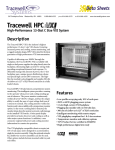
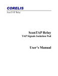
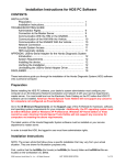
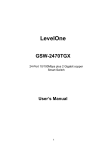
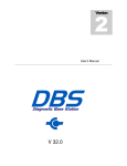
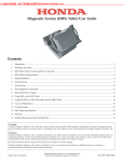
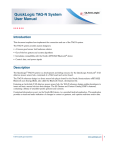
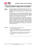
TERADYNE
GNA600
GATEWAY DEVICE
USER GUIDE FOR
HONDA VEHICLES
© 2007 American Honda Motor Co., Inc. – All Rights Reserved
AST 33196-36945 (0706)
GNA600 Gateway Device User Guide
CONTENTS
1
1.1
1.2
1.3
COMPLIANCE
FCC Statement
Use of This Equipment in Canada
Use of This Equipment in the European Union
2
2
2
2
2.1
2.2
SAFETY PRECAUTIONS
Basic Safety Precautions
Proper Installation and Use of This Equipment
3
3
4
3.1
3.2
3.3
INTRODUCTION
Overview
GNA600 Kit
Description of Parts
5
5
6
7
4.1
4.2
4.3
SOFTWARE USE
Overview
Use With HDS Software
Use With Control Module Update Software
9
9
10
11
5.1
5.2
5.3
5.4
SETUP
Before You Start
Setup Basics
Connection With the USB PC Interface Cable
Connection With an Ethernet Cable
12
12
12
13
13
6.1
6.2
6.3
UPDATING CONTROL UNITS/MODULES
Overview
Control Unit/Module Update in Pass-thru Mode
Control Unit/Module Update in Storage Mode
15
15
17
22
7.1
7.2
7.3
TROUBLESHOOTING
Cannot Communicate with the Host PC
Cannot Communicate with the Vehicle
GNA600 LED Patterns
25
25
25
26
8.1
8.2
8.3
CARE AND MAINTENANCE
Cleaning the GNA600 Unit
Cable Care
PCMCIA Memory Card Compartment Lid
27
27
27
27
9.1
SPECIFICATIONS
Hardware
28
28
10.1
10.2
SUPPORT INFORMATION
Warranty
Customer Service Assistance
29
29
30
2
3
4
5
6
7
8
9
10
AST 33196-36945 (0706)
1 of 30
1 – COMPLIANCE
1.1
FCC Statement
The United States Federal Communications Commission (in 47 CFR 15.105) has specified
that the following notice be brought to the attention of users of this equipment.
This equipment has been tested and found to comply with the limits for a Class “A” digital
device, pursuant to part 15 of the FCC rules. These limits are designed to provide reasonable
protection against harmful interference when the equipment is operated in a commercial
environment. This equipment generates, uses, and can radiate radio frequency energy and, if
not installed in accordance with the instruction manual, may cause harmful interference to
radio communications. Operation of this equipment in a residential area is likely to cause
harmful interference, in which case the user will be required to correct the interference at his or
her own expense.
Users may find the following booklet prepared by the FCC to be useful: How to Resolve
Radio/TV Interference Problems. This booklet is available from the U.S. Government Printing
Office, Washington, DC 20402. Stock # 004-000-00345-4.
1.2
Use of This Equipment in Canada
This digital apparatus does not exceed Class “A” limits for radio emissions from digital
apparatus as set out in the Radio Interference Regulations of the Canadian Department of
Communications (DOC).
1.3
Use of This Equipment in the European Union
NOTE − This is a Class A product. In a domestic environment this product may
cause radio interference in which case the user may be required to take adequate
measures.
This product has been designed and tested primarily for use in a commercial/light industrial
environment. It has been tested for higher levels of R.F. field immunity up to those levels
required for automotive products, but in safety-critical applications, its use in the proximity of
the following operating devices must be avoided: mobile telephones, amateur radio,
emergency services and CB transceivers, other forms of mobile radio communications,
TV/radio broadcast and relay transmitters, radar transmitters, and similar devices.
AST 33196-36945 (0706)
2 of 30
2 – SAFETY PRECAUTIONS
2.1
Basic Safety Precautions
Underwriters Laboratories, the North American standards agency, requires that the suppliers
of all garage equipment bring the following notice to users in North America. While the
requirement is specific to North America, users elsewhere are advised to follow the same
precautions. When using your equipment, follow these basic safety precautions:
1.
2.
3.
4.
5.
6.
7.
8.
9.
10.
11.
12.
13.
14.
15.
Read all instructions.
Take care to avoid burns from touching hot parts.
Do not operate equipment with a damaged cord.
If the equipment has been dropped or damaged, do not operate it until examined by
qualified service personnel.
Do not let the cord hang over the edge of a table, bench, or other counter surface, or
come in contact with hot manifolds or moving fan blades.
If an extension cord is necessary, a cord with a current rating equal to or more than that
of the equipment should be used. Cords rated for less current than the equipment may
overheat. Take care to arrange the cord so that it will not be tripped over or pulled
accidentally.
Always unplug the equipment from the electrical outlet when not in use. Never use the
cord to pull the plug from the outlet. Grasp the plug and pull it to disconnect.
Let the equipment cool completely before putting it away. Loop the cord loosely around
the equipment when storing it.
To reduce the risk of fire, do not operate the equipment near open containers of
flammable liquids.
When working on operating internal combustion engines, make sure you have adequate
ventilation.
Keep hair, loose clothing, and all body parts away from moving parts.
To reduce the risk of electric shock, do not use the equipment on wet surfaces or
expose it to rain or any other fluid.
Use the equipment only as directed in the manual. Use only the equipment supplier’s
recommended attachments. Use of non-recommended parts may invalidate the
equipment warranty.
ALWAYS WEAR SAFETY GLASSES. Everyday eyeglasses only have impact-resistant
lenses; they are NOT safety glasses.
While using the GNA600, ensure that the auto DLC cable does not get trapped between
the door and the vehicle body.
AST 33196-36945 (0706)
3 of 30
2.2
Proper Installation and Use of This Equipment
This equipment has been designed, manufactured, and tested to meet the requirements of
international standards; however, like any apparatus, care must be taken in its use.
The GNA600 has a 230/110V AC input to the power supply and is supplied with a power cord.
The electrical power source outlet socket must be located adjacent to the equipment, and it
must be easily accessible and readily identifiable to the operator as the means of
disconnection of the electrical power source to this equipment.
For continued protection against electric shock, certain parts of this equipment, including the
PC compatible signal interface connections, have been designed such that the voltage is
limited to a safe value. To maintain this level of protection, equipment connected to this
equipment must have interface connections that are similarly protected.
DO use this equipment in accordance with the operating procedures.
DO switch this equipment off (unplug the AC charger power cord at the electrical socket outlet
if necessary) before carrying out maintenance and cleaning operations (refer to the Care and
Maintenance section). Use only a well-diluted, mild, non-abrasive cleaning agent applied by
using a soft, lint-free cloth.
DO NOT allow the GNA600 to operate below or within 460 mm (18 in.) of the floor.
DO NOT use this equipment outside the supplier specifications.
DO NOT use or apply undiluted cleaning agent directly to the equipment surface, and do not
soak the cloth. Take care that cleaning fluid does not enter electrical connector receptacles.
DO NOT immerse equipment in water.
DO NOT continue to use this equipment if you have ANY doubt that it may not be working
properly or is damaged in any way. Remove the power source to the equipment.
DO NOT connect any equipment to the PC-compatible signal interface connections of the
GNA600 until you are satisfied that the equipment is safe.
DO NOT remove any fixed covers unless you are authorized/qualified to do so for the
preparation of this equipment.
DO NOT obstruct ventilation of this equipment. Obstruction can cause overheating and
reduced reliability, shortening the life of this equipment.
DO NOT expose this equipment to spilled liquids or any types of fluid.
DO NOT replace detachable power cords with a different type (or fuse rating) from that
detailed in the documentation or supplied with this equipment.
AST 33196-36945 (0706)
4 of 30
3 - INTRODUCTION
3.1 Overview
The GNA600 is a vehicle interface device with the speed and storage capacity required to
update control units/modules in vehicle systems that use the CAN (control area network)
communications protocol on the DLC (data link connector). The GNA600 does all the functions
of the HIM (Honda Interface Module) but with additional capabilities.
The GNA600 is easiest to use with a wired USB connection, but it can also be used with an
Ethernet connection. Here are the two connection configurations:
Wired connection with the USB PC Interface Cable (easiest connection):
USB PC INTERFACE CABLE
To vehicle’s DLC.
DLC CABLE
Wired connection with an Ethernet cable and the PC Interface Adapter Block* (optional
connection):
ETHERNET CABLE
PC INTERFACE
ADAPTER BLOCK
To vehicle’s DLC.
DLC CABLE
* This is an optional part that can be purchased separately.
AST 33196-36945 (0706)
5 of 30
3.2 GNA600 Kit
3
5
4
6
7*
1
2
8
9*
1.
2.
3.
4.
5.
6.
7.
8.
9.
Part Name
Part Number
GNA600 Unit
USB PC Interface Cable
DLC Cable
Power Supply Unit
Power Supply Cord
Trigger Switch Adapter Block (Yellow)
PC Interface Adapter Block (Blue)*
Trigger Switch
256 MB PCMCIA Memory Card*
TDS35540000
TDS35525406
TDS35541433
TDS60678010
TDS35481214
TDS35541434
TDS35541441
TDS35541359
SSDP25M3012
* These are optional parts that can be purchased separately.
AST 33196-36945 (0706)
6 of 30
3.3 Description of Parts
GNA600 Unit
(TDS35540000)
The main communications unit between the vehicle
and the PC.
USB PC Interface Cable
(TDS35525406)
Connects the GNA600 to a PC for transferring
software and data, and to display diagnostic data
on the PC screen.
DLC Cable
(TDS35541433)
Connects the GNA600 to the vehicle’s 16-pin DLC.
Power Supply Unit
(TDS60678010)
Provides A/C power to the GNA600 when it is not
connected to a vehicle.
Power Supply Cord
(TDS35481214)
Connects the Power Supply Unit to A/C power.
Trigger Switch Adapter Block (Yellow)
(TDS35541434)
Connects the trigger switch (NUD420094) to the
GNA600 for control unit/module updating in
Storage Mode (without a PC).
AST 33196-36945 (0706)
7 of 30
PC Interface Adapter Block (Blue)*
(TDS35541441)
Connects the PC to the GNA600 through a
standard PC Ethernet cable (cable not included).
NOTE − The PC Interface Adapter Block is not needed if you connect the PC
to the GNA600 with the USB PC Interface Cable (TDS35525406).
Trigger Switch
(TDS35541359)
When it is connected to the Trigger Switch Adapter
Block (TDS35541434), the Trigger Switch allows
the GNA600 to update control units/modules in
Storage Mode (without a PC). Not all software runs
in Storage Mode. Refer to each software package
to see if it can run in Storage Mode.
256 MB PCMCIA Memory Card*
(SSDP25M3012)
This memory card is used by the GNA600 (in
Storage Mode) for updating (reprogramming)
control units/modules.
To order replacement parts, call the Honda Tool and Equipment Program at 1-888-424-6857.
* These are optional parts that can be purchased separately.
AST 33196-36945 (0706)
8 of 30
4 – SOFTWARE USE
4.1 Overview
The GNA600 can be used with two different software suites that are distributed with each HDS
installation disc, and can be installed from your service department Master/Server to your iN
(Interactive Network) workstation computer. To install HDS PC software, refer to the ISIS
publication entitled, Installation Instructions for HDS PC Software.
The GNA600 can be used with both HDS software and Control Module (CM) Update software.
Once installed from the Master/Server to the iN workstation computer, either software can be
run by double clicking on its associated icon on the iN workstation computer screen.
Diagnostic System
CM Update
AST 33196-36945 (0706)
9 of 30
4.2 Use With HDS Software
The GNA600 can be selected as the
default vehicle interface during installation
of the HDS software or from the setup
screen.
After you select the
GNA600 as the interface,
its icon appears in the top
right corner of the HDS
intro screen. This icon
means your PC is
connected to the
GNA600.
No connection between the PC and GNA600.
Connection OK between PC and GNA600. This does not indicate
a connection to a vehicle.
AST 33196-36945 (0706)
10 of 30
4.3 Use With Control Module Update Software
The GNA600 can be selected as the default
vehicle interface during installation of the
Control Module (CM) Update software or from
the setup screen.
The LED patterns seen on
various screens during use
of the CM Update software
should mimic the LED
patterns on the GNA600.
(Refer to section 7.3 for
details on GNA600 LED
patterns.)
Normal use
For use with
trigger switch
Setup
screen
Version
information
AST 33196-36945 (0706)
11 of 30
5 - SETUP
5.1 Before You Start
For the initial setup of the GNA600, the latest version of HDS software must be installed on the
host PC.
We strongly recommend using the USB PC Interface Cable (TDS35525406) as your wired
connection to the GNA600. The correct device drivers for the USB PC Interface Cable are
included with the HDS software. If an Ethernet cable is used for your wired connection, you will
need to do extra steps.
NOTE − Setup of the GNA600 connection is fully automatic if you have the correct
drivers from the HDS software installed, use the USB PC Interface Cable, and
carefully follow the set up instructions. If you use an Ethernet cable, you must do a
manual setup of the GNA600 connection (see section 5.4).
5.2 Setup Basics
Here are the basics in setting up the GNA600 connection:
•
•
•
•
Install the latest HDS software from the HDS installation disc.
Connect the USB PC Interface Cable into any free USB port, and wait for the device
drivers to complete the installation.
Connect the GNA600 to the USB PC Interface Cable.
Power up the GNA600 using its Power Supply Unit and Cord. The GNA600 is now
ready for a wired connection to a vehicle.
For more setup information, see section 5.3.
AST 33196-36945 (0706)
12 of 30
5.3 Connection With the USB PC Interface Cable
When the USB PC Interface Cable is used, the connection is fully automatic after you install
the latest HDS software from the HDS installation disc. The HDS software includes the correct
device drivers to work with the USB PC Interface Cable.
USB PC INTERFACE CABLE
To vehicle’s DLC.
DLC CABLE
5.4 Connection With an Ethernet Cable
To use an Ethernet connection, you must configure the network adapter on the PC to a static
address and use a straight through Ethernet cable (not supplied). You must also connect the
PC Interface Adapter Block* (TDS35541441) between the Ethernet cable and the GNA600.
ETHERNET CABLE
PC INTERFACE
ADAPTER BLOCK
To vehicle’s DLC.
DLC CABLE
To establish the Ethernet connection, install a second network adapter card in the host PC.
This allows for a connection to the Internet on one card and a connection to the GNA600 on
the other.
* This is an optional part that can be purchased separately.
AST 33196-36945 (0706)
13 of 30
On the PC, set the network adapter to a static IP
address of 192.168.0.1 or 172.16.0.1, with a subnet
mask of 255.255.255.0. Use an address that does not
conflict with other network settings on that PC. No
gateway or DNS settings are required. Once the
address is set, restart the PC, launch the HDS
software, and verify that the GNA600 icon in the top
right corner of the screen has a green light.
AST 33196-36945 (0706)
14 of 30
6 – UPDATING CONTROL UNITS/MODULES
6.1 Overview
The GNA600 can be used to update (reprogram) any Honda control unit or module with
EEPROM (electronically erasable programmable read only memory) storage. Currently,
EEPROM handles the software storage in some PGM-FI and automatic transmission control
units/modules.
The GNA600 is much faster than the HIM (Honda Interface Module) that it replaces. You will
see rapid upload times from the PC to the GNA600 and also from the GNA600 to vehicles that
use the new CAN (control area network) protocol. Based on the communication protocol used,
connection speed between the GNA600 and different vehicles will vary.
To update control units/modules, the CM Update software must be loaded into the PC used
with the GNA600. The CM Update software has been enhanced to show the progress during
the update, as well as showing on-screen instructions and the LED patterns you will see on the
GNA600.
The CM Update software can be used in Pass-thru Mode or Storage Mode. Pass-thru Mode is
used when the GNA600 can be connected to the PC and vehicle at the same time. Storage
Mode is used when the GNA600 cannot be connected to the PC and vehicle at the same time.
Each CM Update software program is identified by its program ID, program part number,
vehicle specifics, and update description. An example is shown below.
CAUTION − During a control unit/module update, the vehicle battery voltage must
remain constant. Failure to maintain battery voltage can damage the vehicle’s
ECM/PCM. Before doing an update, test the vehicle’s battery and continue only if the
battery passes the test (see Honda Service Bulletin 88-023, Battery Test Procedure).
To help maintain battery voltage during the update, connect the battery to a battery
booster, and turn off all lights and accessories.
AST 33196-36945 (0706)
15 of 30
As shown to the right, the CM Update
software is launched from the Windows
Start menu. To do control unit/module
updates, the latest HDS installation disc
software must be installed (see section
4).
AST 33196-36945 (0706)
16 of 30
6.2 Control Unit/Module Update in Pass-thru Mode
NOTE:
• These instructions are a summary of the updating process.
• For a description of the GNA600 Kit parts used in this procedure, refer to section 3.3.
• For a description of the GNA600 LED patterns, see section 7.3.
1. Connect the USB PC Interface Cable to the iN Workstation and to the GNA600. From the
Updating Honda Control Modules main screen, select Pass-thru Mode.
2. Connect the DLC Cable to the GNA600 and to the vehicle’s DLC. (You don’t need to turn
the ignition switch to ON (II) before connecting the GNA600. This applies only to the HIM.)
3. Turn the ignition switch to ON (II), and wait until the green #2 LED on the GNA600 stays on.
Click on the Check Mark to continue.
AST 33196-36945 (0706)
17 of 30
4. Select the vehicle system that you are updating, then click the Check Mark on the right side
of the screen.
5. Verify that the Program ID and the Program Part No. are for the system you selected in step
4, then click on the Check Mark.
AST 33196-36945 (0706)
18 of 30
6. Confirm the control module update by Program ID and Program Part No. Make sure this
corresponds with any information provided in the service bulletin for the update you are
doing. Click on Yes to continue. The CM Update software loads the program file onto the
GNA600. This takes only a few seconds.
AST 33196-36945 (0706)
19 of 30
7. Click on the Check Mark to begin the control unit/module update.
NOTE: On non-CAN vehicles, the update can take 15 to 30 minutes.
CAUTION − To avoid ECM/PCM damage, do not interrupt the update.
AST 33196-36945 (0706)
20 of 30
8. Once the update is completed, turn the ignition switch to LOCK (0), and then back to ON (II)
within 60 seconds.
9. Once the software verifies that the control unit/module has been successfully updated, click
on Yes to update another vehicle, or click on No to exit the update program.
AST 33196-36945 (0706)
21 of 30
6.3 Control Unit/Module Update in Storage Mode
NOTE:
•
•
•
Storage Mode works similar to Pass-thru Mode. You will see the same CM Update
software screens during the vehicle system selection. To complete a Storage Mode
update at the vehicle, you need the Trigger Switch Adapter Block (TDS35541434)
and the Trigger Switch (TDS35541359).
These instructions are a summary of the updating process.
For a description of the GNA600 Kit parts used in this procedure, refer to section
3.3.
1. Connect the USB PC Interface Cable to the iN Workstation and to the GNA600. From the
Updating Honda Control Modules main screen, select Storage Mode and follow the onscreen instructions.
2. Connect the DLC Cable to the GNA600 and to the vehicle’s DLC. (You don’t need to turn
the ignition switch to ON (II) before connecting the GNA600. This applies only to the HIM.)
3. Turn the ignition switch to ON (II), and wait until the green #2 LED on
the GNA600 stays on. Turn the ignition switch off, and disconnect the
DLC Cable from the vehicle.
4. Connect the USB PC Interface Cable to the iN Workstation and to
the GNA600. Connect the Power Supply Unit and Power Supply
Cord to the GNA600. The GNA600 will start a self-check. After
about 30 seconds, the GNA600 LEDs flash green and yellow.
5. Select the vehicle system that you are updating, then click on the Check Mark on the right
side of the screen.
AST 33196-36945 (0706)
22 of 30
6. Verify that the Program ID and the Program Part No. are for the system you selected in step
5, then click on the Check Mark.
7. Confirm the control module update by Program ID and Program Part No. Make sure this
corresponds with any information provided in the service bulletin for the update you are
doing. Click on Yes to continue. The CM Update software loads the program file onto the
GNA600. This takes only a few seconds.
AST 33196-36945 (0706)
23 of 30
8. Disconnect the GNA600 from the USB PC Interface Cable, then connect the Trigger Switch
Adapter Block and the Trigger Switch to the GNA600 as shown below.
NOTE: The DLC cable should still be connected to the GNA6000.
9. Reconnect the DLC Cable to the vehicle’s DLC.
10. Turn the ignition switch to ON (II), and wait until the green #2 LED on
the GNA600 stays on. Press and release the trigger switch button.
11. The yellow #1 LED blinks, and the green #2 LED stays on. This
indicates that the control unit/module is being updated.
NOTE: On non-CAN vehicles, the update can take 15 to 30 minutes.
CAUTION − To avoid ECM/PCM damage, do not interrupt the update.
12. When the #1 LED stays on and the #2 LED goes out, turn the ignition
switch off.
13. Turn the ignition switch to ON (II). When the #1 and #2 LEDs stay on,
the control unit/module update is completed.
14. Turn the ignition switch off, and disconnect the DLC Cable from the vehicle. The software
update is stored in the GNA600. To do the same update on an other vehicle, repeat steps 9
thru 14.
AST 33196-36945 (0706)
24 of 30
7 – TROUBLESHOOTING
If you have either of the two problems listed below, do the checks for each problem. If these
checks do not solve the problem, call the appropriate number below.
• If you are a Honda dealer, call the American Honda Special Tools Hotline at 800-346-6327.
• If you are not a Honda dealer, call 800-210-8699.
7.1 Cannot Communicate With the Host PC
1. Check that the DLC Cable is properly connected to the GNA600 and to the vehicle’s DLC.
2. If you are using the GNA600 in Storage Mode, make sure the Power Supply Unit and the
Power Supply Cord are properly connected.
3. Make sure the USB PC Interface Cable is properly connected to the GNA600 and to the iN
workstation computer. To verify this connection, look for the HDS icon in the top right
corner of the PC screen.
4. Verify that the latest version of HDS or CM Update software is installed on the iN
workstation computer.
5. Check that the market and dealer numbers are set up correctly.
6. Restart the software on the iN workstation computer, then power the GNA600 off and on.
7.2 Cannot Communicate With the Vehicle
1. Check that the DLC Cable is properly connected to the GNA600 and to the vehicle’s DLC.
2. Make sure the USB PC Interface Cable is properly connected to the GNA600 and to the iN
workstation computer. To verify this connection, look for the HDS icon in the top right
corner of the PC screen.
3. Check that the ignition switch is turned to ON (II).
4. Verify that the latest version of HDS or CM Update software is installed on the iN
workstation computer.
5. Check that the market and dealer numbers are set up correctly.
6. Check that the GNA600 is selected as the communications device.
7. Check for broken or missing terminal pins on the DLC Cable ends.
8. Restart the software on the iN workstation computer, then power the GNA600 off and on.
AST 33196-36945 (0706)
25 of 30
7.3 GNA600 LED Patterns
YELLOW
#1
GREEN
#2
RED
#3
OFF
BLINKS
OFF
Self-test during the power up.
BLINKS
BLINKS
OFF
Searching for a valid connection to
the PC or the control unit/module.
BLINKS
BLINKS
BLINKS
PATTERN DESCRIPTION
Communicating with the PC.
BLINKS
ALTERNATELY
OFF
Gathering information from the
control unit/module.
OFF
ON
OFF
Ready for updating.
BLINKS
ON
OFF
Updating is in progress.
ON
OFF
OFF
The control unit/module has been
updated. Turn off the ignition
switch.
OFF
The ignition switch is on, and the
Program ID and DTCs are being
checked.
OFF
The control unit/module update is
successful, or the control
unit/module was already updated.
BLINKS
ON
OFF
ON
OFF
ON
BLINKS
OFF
ON
ON
AST 33196-36945 (0706)
An incorrect control unit/module
calibration was selected, or the
GNA600 needs to be
reprogrammed.
GNA600 device error. Disconnect
the power.
26 of 30
8 - CARE AND MAINTENANCE
8.1 Cleaning the GNA600 Unit
WARNING − Switch off the power to the GNA600 Unit, and disconnect all electrical
cables before cleaning it.
•
Clean the GNA600 Unit with a non-abrasive, mild cleaning agent only. Apply the cleaner to
a soft, lint free cloth, then lightly rub the unit with the cloth. Never apply the cleaner directly
to the unit.
•
Do not soak the cleaning cloth, and do not allow cleaning fluid to enter the electrical
connectors.
•
Do not use abrasive cleaners or any type of polish.
•
If dust or other particles get on the GNA600 Unit, lightly brush the unit off with a soft, lint
free cloth.
8.2 Cable Care
•
Always return the cables to their appropriate storage area. The cables can be damaged if
they are driven over or exposed to excessive temperatures.
•
To avoid damaging the cable ends and the adapter blocks, always connect and disconnect
these parts slowly and carefully.
8.3 PCMCIA Memory Card Compartment Lid
•
Once the PCMCIA card* has been installed and configured, keep the compartment lid
secured to the GNA600 Unit.
•
To avoid damaging the compartment lid seal, install the PCMCIA card slowly and carefully.
* This is an optional part that can be purchased separately.
AST 33196-36945 (0706)
27 of 30
9 - SPECIFICATIONS
9.1 Hardware
GNA600 Unit
Rating: 8V – 18V DC (12V nominal) at 4 Amps (maximum)
Vehicle Protocols: SCP
UBP
CAN (High & Medium Speed)
ISO-9141
WEN
SCS
DIAG-H
Host Protocols: Ethernet 10/100 Base T
RS-232
USB
Vehicle Connection: Detachable 2.9 m (9.4 ft) cable with molded DLC connector
Enclosure: Magnesium, service bay fluid resistant,
1m freefall test impact resistant
Dimensions: Height – 37 mm (1.46 in)
Width – 80 mm (3.15 in)
Length – 155 mm (6.1 in)
Weight: 268 g (9.4 oz) without cables
Environmental: Operating Temp: 0ºC to 40ºC (32ºF to 104ºF)
at 15% to 85% RH non-condensing
Storage: -20ºC to 70ºC (-4ºF to 158ºF)
at 15% to 85% RH non-condensing
Standards and Regulatory The GNA600 fulfils the requirements of the CE marking
Compliances: scheme and UL201 – Garage Equipment
256 MB PCMCIA Memory Card*
Manufacturer:
Manufacturer’s Part Number:
Type:
Capacity:
Environmental:
Silicon Systems
SSD-P25M-3012
Industrial Grade ATA Flash Card
256 MB
Operating Temp: 0ºC to 70ºC (32ºF to 158ºF)
High shock and vibration resistance, MIL-STD 810F.
Standards and Regulatory
Compliances: Supports “fixed-disk” mode and DMA enabled
* This is an optional part that can be purchased separately.
AST 33196-36945 (0706)
28 of 30
10 - SUPPORT INFORMATION
10.1 Warranty
The GNA600 Unit is covered by a 5-year limited warranty. All other parts of the GNA600 Kit
are covered by a 1-year limited warranty and can be purchased separately.
The limited warranty applies to normal use only. It does not cover any damage or defects
arising from
•
Failure to use the GNA600 according to the written instructions of Teradyne or American
Honda, or use with vehicles, motors, or systems other than those for which it was designed.
It is particularly important to follow all written instructions in any software used with
the GNA600 relating to required cable connections. Failure to follow these
instructions can result in permanent damage to the GNA600. Such damage is not
covered by this warranty.
•
Neglect or misuse of the GNA600 Kit including any damage arising from accident, abuse,
or disaster.
•
Any alteration, modification, or maintenance of the GNA600 Kit by a party other than
Teradyne or without Teradyne’s prior written consent.
•
The use of parts or accessories not approved by Teradyne.
•
Any lost parts, or parts that fail from normal wear and tear.
Neither Teradyne nor American Honda is responsible for any resultant damage caused to third
party equipment.
AST 33196-36945 (0706)
29 of 30
10.2 Customer Service Assistance
1. Make sure you do the troubleshooting steps in section 7 before you call.
2. If you are a Honda dealer and need assistance with the GNA600 hardware or software, call
the American Honda Special Tools Hotline at 800-346-6327. If you are not a Honda dealer,
call 800-210-8699. If you have a verified hardware problem with the GNA600 Unit, a
replacement unit will be shipped to you. Prepaid freight documents will be provided for you
to return the defective equipment.
3. Have this information handy before you make your call:
• Dealer number
• GNA600 serial number
• Vehicle year and model
• Vehicle system
• Description of problem
Disclaimer
Information in this document is subject to change without notice. American Honda Motor Co.
does not make any representations or warranties (implied or otherwise) regarding the accuracy
and completeness of this document and shall in no event be liable for any loss of profit or any
other commercial damage, including but not limited to special, incidental, consequential, or
other damages. Commercial product used does not constitute an endorsement or
recommendation. No part of this document may be reproduced or transmitted in any form by
any means without the express written permission of America Honda Motor Co. All brand
names and product names used in this document are trademarks or registered trademarks of
their respective holders.
AST 33196-36945 (0706)
30 of 30