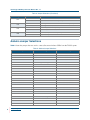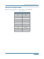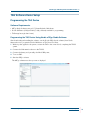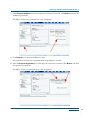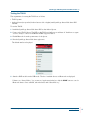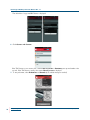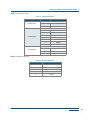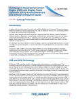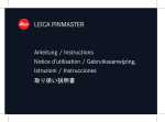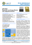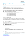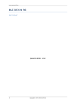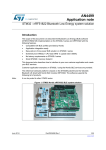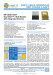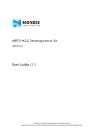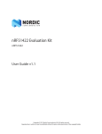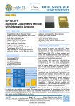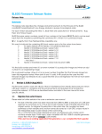
1
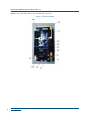
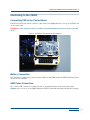
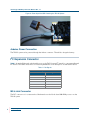
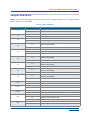
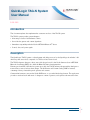
QuickLogic TAG-N System
User Manual
••••••
Introduction
This document explains how implement the connection and use of the TAG-N system.
The TAG-N system provides system designers:
• A known-good sensor hub hardware solution
• Out-of-the-box gesture and context algorithms
• Immediate compatibility with the Nordic nRF51822 Bluetooth® device
• Control, data, and power signals
Description
The QuickLogic® TAG-N system is a development and debug resource for the QuickLogic ArcticLink® 3 S2
ultra-low power sensor hub, comprised of a TAG board and carrier board.
The TAG-N reference design is a direct sensor hub plug-in board for the Nordic Semiconductor nRF51822
Bluetooth Low Energy (BLE), also called the Bluetooth Smart, development kit.
Featuring an ArcticLink 3 S2 ultra-low power sensor hub, the TAG-N reference design enables developers to
insert and test a sensor hub into their designs. The S2 Gesture and Context Catalog CSSP is featured,
containing a library of wearable-specific gestures and contexts.
Contextual information is sent, via the Nordic BLE device, to a provided Android application. This application
provides a visual and audio indication of changes in context or gestures, and captures real-time sensor data.
•
© 2015 QuickLogic Corporation
www.quicklogic.com ••
•
•
•
1
QuickLogic TAG-N System User Manual Rev. 1.1
Figure 1 shows the TAG carrier board and labels the connectors.
Figure 1: TAG Carrier Board
•
2 •• www.quicklogic.com
•
•
•
© 2015 QuickLogic Corporation
QuickLogic TAG-N System User Manual Rev. 1.1
Interfacing to the TAG-N
Connecting TAG to the Carrier Board
The TAG board plugs into the P1 connector of the carrier board. Figure 2 shows a close-up of the TAG board
on the carrier board.
WARNING: Ensure the power (battery and USB) are disconnected before inserting or removing the TAG
board.
Figure 2: Close-Up of TAG Board on Carrier Board
Battery Connection
P2 is the battery connection the powers the entire TAG-N system (USB and Nordic nRF518 DK-based power
options are also available).
USB Power Connection
P3 is a Micro USB connection for external power for charging the battery and powering the system.
Figure 3 shows a close-up of the USB powering the TAG-N system with the battery attached and charging.
•
© 2015 QuickLogic Corporation
www.quicklogic.com ••
•
•
•
3
QuickLogic TAG-N System User Manual Rev. 1.1
Figure 3: Close-Up of the USB Powering the TAG-N System
Arduino Power Connection
The TAG-N system can be powered through the Arduino connector. This will also charge the battery.
I2C Expansion Connector
Table 1 shows the P18 signals, which enable access to the TAG-N system I2C signals for connecting additional
I2C devices. The GPIO connection is for future implementation of an interrupt for an external I2C device.
Table 1: P18 Signals
P18 I2C Expansion Connector
Pin
Signal
1
I2C SDA
2
GND
3
3.3V
4
I2C SCL
5
1.8V
6
S2 GPIO D2
M0 J-Link Connector
The P17 connector is for connection the J-Link interface to the Nordic-based M0 ARM processor on the
TAG-N system.
•
4 •• www.quicklogic.com
•
•
•
© 2015 QuickLogic Corporation
QuickLogic TAG-N System User Manual Rev. 1.1
M0 Serial Port Connector
Table 2 shows the P16 signals. which is the serial port output from the Nordic-based M0 ARM processor. The
signaling is RS-232. The pinout of this 10-pin connector is arranged so a common 10-pin to DB-9 cable can
be used.
Table 2: P16 Signals
P16 Serial Port Connector
Pin
Signal
3
RxD
4
RTS
5
TxD
6
CTS
9
GND
Figure 4 shows a close-up of the serial port and J-link connected.
Figure 4: Close-Up of Serial Port and J-Link Connected
•
© 2015 QuickLogic Corporation
www.quicklogic.com ••
•
•
•
5
QuickLogic TAG-N System User Manual Rev. 1.1
Figure 5 show a typical J-link interface device.
Figure 5: Typical J-Link Interface Device
P19 J-Link Connector
The P19 connector is reserved for future use.
P15 Serial Port Connector
The P15 connector is reserved for future use.
•
6 •• www.quicklogic.com
•
•
•
© 2015 QuickLogic Corporation
QuickLogic TAG-N System User Manual Rev. 1.1
Jumper Selections
Table 3 shows the TAG-N jumpers and headers that are used to configure and give access to signals. Default
jumper settings are recommended.
Table 3: Jumper Selections
Jumper
J1
J2
J3
J4
Connection
1-2
J6
Charger powered by Arduino
1-2
TAG charger powered (default)
None
TAG-N powered by USB (default)
2-3
TAG-N powered by battery
1-2
TAG Sensor 3.3V powered by TAG-N
(TAG must be modified)
1-2
Reserved for future use
Reserved for future use
None
Reserved for future use
1-2
1-2
1-2
None
J9
1-2
None
J10
J11,J12
J13,J14
J15
TAG Sensor 1,8V powered by TAG-N
(TAG must be modified)
TAG Sensor 1,8V not powered by TAG-N (default)
TAG Nordic 1.8V powered by TAG-N
(TAG must be modified)
TAG Nordic 1.8V not powered by TAG-N (default)
TAG S2 I/O 1.8V powered by TAG-N
(TAG must be modified)
TAG S2 I/O 1.8V not powered by TAG-N (default)
TAG S2 Core 1.2V powered by TAG-N
(TAG must be modified)
TAG S2 Core 1.2V not powered by TAG-N (default)
1-2
Reserved for future use
2-3
Reserved for future use
1-2,3-4
Reserved for future use
1-3,2-4
Reserved for future use
1-2,3-4
TAG M0 Serial Port normal (default)
1-3,2-4
TAG M0 Serial Port null modem
1-2
Button S1 will function as Reset (SWDIO low) (default)
2-3
M0 will be disabled (nReset low)
None
J16
TAG Sensor 3.3V not powered by TAG-N (default)
2-3
None
J8
TAG charger not powered
1-2
None
J7
Charger powered by MicroUSB (default)
2-3
None
J5
Result
1-2
None
No reset control
Button S2 is connected to S2 GPIO D4
Button S2 is not connected to S2 device (default)
•
© 2015 QuickLogic Corporation
www.quicklogic.com ••
•
•
•
7
QuickLogic TAG-N System User Manual Rev. 1.1
Table 3: Jumper Selections (Continued)
Jumper
Connection
1-2
J17
None
1-2
J18
None
1-2
J19
None
1-2
J20
None
Result
S2 GPIO D5 is connected to the TAG-N LED D4
S2 GPIO D5 is not connected (default)
S2 CFG_DN is connected to the TAG-N LED D4 (default)
S2 CFG_DN is not connected
TAG battery is connected (default)
TAG battery is not connected
TAG-N battery is connected (default)
TAG-N battery is not connected
Arduino Jumper Selections
Table 4 shows the jumpers that are used to connect/disconnect Arduino GPIOs from the TAG-N system.
Table 4: Arduino Jumper Selections
Jumper
TAG Signal
Arduino Signal
P4 1-2
-
Arduino Vdd 1
P4 3-4
-
Arduino Vdd 2
P4 5-6
M0 SWDIO
Arduino Reset
P4 7-8
-
Arduino Vdd 3
P4 9-10
V_ARDUINO_5V
Arduino 5V
P4 11-12
GND
Arduino GND
P4 13-14
GND
Arduino GND
P4 15-16
-
Arduino Vin
P4 5-6
-
Arduino Vdd 2
P6 1-2
-
Arduino GPIO 0.01
P6 3-4
-
Arduino GPIO 0.02
P6 5-6
-
Arduino GPIO 0.03
P6 7-8
-
Arduino GPIO 0.04
P6 9-10
-
Arduino GPIO 0.05
P6 11-12
-
Arduino GPIO 0.06
P8 1-2
M0 UART CTS
Arduino GPIO 0.20
P8 3-4
M0 UART TXD
Arduino GPIO 0.23
P8 5-6
-
Arduino GPIO 0.24
P8 7-8
-
Arduino GPIO 0.25
P8 9-10
M0 SPI CS_N
Arduino GPIO 0.28
P8 11-12
M0 SPI SCLK
Arduino GPIO 0.29
P8 13-14
-
Arduino GND
P8 15-16
-
Arduino GPIO 0.00
•
8 •• www.quicklogic.com
•
•
•
© 2015 QuickLogic Corporation
QuickLogic TAG-N System User Manual Rev. 1.1
Table 4: Arduino Jumper Selections (Continued)
Jumper
TAG Signal
Arduino Signal
P8 17-18
M0 SPI MISO
Arduino GPIO 0.30
P8 19-20
M0 SPI MOSI
Arduino GPIO 0.07
P10 1-2
S2 SPI RST_N
Arduino GPIO 0.12
P10 3-4
S2 SYS_RST_N
Arduino GPIO 0.13
P10 5-6
-
Arduino GPIO 0.14
P10 7-8
S2 CFG_DN
Arduino GPIO 0.15
P10 9-10
-
Arduino GPIO 0.16
P10 11-12
S2 INT_OUT
Arduino GPIO 0.17
P10 13-14
TAG-N LED
Arduino GPIO 0.18
P10 15-16
TAG-N Button S2
Arduino GPIO 0.19
P12 1-2
M0 UART RXD
Arduino GPIO 0.21
P12 3-4
M0 UART RTS
Arduino GPIO 0.22
P12 5-6
-
Arduino GPIO 0.26
P12 7-8
-
Arduino GPIO 0.27
P12 9-10
S2 SPI CS_N
Arduino GPIO 0.08
P12 11-12
S2 SPI SCLK
Arduino GPIO 0.09
P12 13-14
S2 SPI MISO
Arduino GPIO 0.10
P12 15-16
S2 SPI MOSI
Arduino GPIO 0.11
Figure 6 shows the Arduino connector locations.
Figure 6: Arduino Connector Locations
•
© 2015 QuickLogic Corporation
www.quicklogic.com ••
•
•
•
9
QuickLogic TAG-N System User Manual Rev. 1.1
Figure 7 shows the default jumper configuration for Arduino connectors.
Figure 7: Arduino Connector and Jumper Settings
•
10 •• www.quicklogic.com
•
•
•
© 2015 QuickLogic Corporation
QuickLogic TAG-N System User Manual Rev. 1.1
ArcticLink 3 S2 Signal Header
Table 5 shows the header that gives access to the ArcticLink 3 S2 device GPIOs signals.
Table 5: S2 Header
Jumper
TAG Signal
P14 1
GND
P14 2
GND
P14 3
S2 GPIO C5
P14 4
-
P14 5
S2 GPIO C3
P14 6
S2 GPIO D5
P14 7
S2 GPIO C2
P14 8
S2 GPIO D4
P14 9
S2 GPIO C0
P14 10
S2 GPIO D3
P14 11
S2 I2C SDA
P14 12
S2 GPIO D2
P14 13
S2 I2C SCL
P14 14
S2 GPIO D1
P14 15
GND
P14 16
GND
•
© 2015 QuickLogic Corporation
www.quicklogic.com ••
•
•
•
11
QuickLogic TAG-N System User Manual Rev. 1.1
Controls and Indicators
Switch SW1
Switch SW1 disconnects the charge power (by default, the MicroUSB) and the battery from the TAG-N system.
Button S1
Button S1 is used as a reset the control for the M0 processor. It can be disabled by Jumper J15.
Button S2
Button S2 can drive Arduino GPIO 0.19. Alternately, it can drive the S2 GPIO D4 by setting Jumper J16.
LED D4
LED D4 is connected to S2 CFG_DN (default), S2 GPIO D5, or Arduino GPIO 0.18, based on Jumpers J17
and J18.
LED D5
LED D5 indicates power is applied to the TAG-N system.
•
12 •• www.quicklogic.com
•
•
•
© 2015 QuickLogic Corporation
QuickLogic TAG-N System User Manual Rev. 1.1
TAG Software Demo Setup
Programming the TAG Device
Software Requirements
• nRFgo Studio Software version 1.17.0 installed with J-link drivers.
• Nordic SoftDevice (s110_nrf51822_7.0.0_softdevice) available for programming.
• TAG image binary (in hex format).
Programming the TAG Device Using Nordic nRFgo Studio Software
After downloading and installing the software, use the Nordic nRFgo Studio software (from Nordic
Semiconductor) to program the Nordic M0 device on TAG board as follows,
1. Without power applied to the system, connect the TAG to the carrier board, completing the TAG-N
system.
2. Connect the J-link interface device to the TAG-N.
3. Connect the battery and optionally, the MicroUSB power,
4. T urn on SW1.
5. Start the nRFgo software.
The nRFgo software introductory screen is displayed.
•
© 2015 QuickLogic Corporation
www.quicklogic.com ••
•
•
•
13
QuickLogic TAG-N System User Manual Rev. 1.1
6. Select nRF51 Programming in the Device Manager subwindow.
The nRFgo Studio, nRF51 programming screen is displayed.
•
14 •• www.quicklogic.com
•
•
•
© 2015 QuickLogic Corporation
QuickLogic TAG-N System User Manual Rev. 1.1
7. Select Program SoftDevice tab on the right side of the main sub-window. Click Browse and select the
SoftDevice program file.
The nRFgo software program SoftDevice screen is displayed.
8. Click Program to program the SoftDevice portion.
A Program Successful message is generated when programming is complete.
9. Select the Program Application tab on the right side of the main sub-window. Click Browse and select
the application program file.
The nRFgo software program application screen is displayed.
•
© 2015 QuickLogic Corporation
www.quicklogic.com ••
•
•
•
15
QuickLogic TAG-N System User Manual Rev. 1.1
10. Click Program to program the Application portion.
A Program Successful message is generated.
The TAG device is now fully programmed.
11. Disconnect the power before removing the TAG from the carrier board or disconnecting the J-link
interface.
12. Connect the battery to the TAG board to run the demo application.
•
16 •• www.quicklogic.com
•
•
•
© 2015 QuickLogic Corporation
QuickLogic TAG-N System User Manual Rev. 1.1
Testing the TAG-N
The requirements for testing the TAG-N are as follows:
• TAG-N system.
• Android phone (not provided, Android version 4.4 or higher) with QuickLogic SensorHub demo APK
installed.
To test the TAG-N:
1. Install the QuickLogic SensorHub demo APK on the Android phone.
2. Power on the TAG-N device. The LED on the TAG board will turn on and then off. It will turn on again
once it is ready to connect to the Bluetooth BLE-supported device.
3. Enable Bluetooth from the system menu of the phone.
4. Run the QuickLogic SensorHub demo application.
The default window is displayed.
5. Switch to BLE mode from the USB mode. The list of available devices on Bluetooth are displayed.
If there is no “SensorHub x.y” (x.y is version of application) in the list, click the SCAN button to scan for
Bluetooth devices. Once available, select the device with “SensorHub x.y”.
•
© 2015 QuickLogic Corporation
www.quicklogic.com ••
•
•
•
17
QuickLogic TAG-N System User Manual Rev. 1.1
The default list of supported BLE demos is displayed.
6. Click Gesture and Context.
If the TAG device is not in motion, the contexts Not on person or Stationary are reported within a few
seconds. If the TAG device is steady, the context Not on person is displayed.
7. To test pedometer, select Pedometer and Sounds (if an audible message is needed).
•
18 •• www.quicklogic.com
•
•
•
© 2015 QuickLogic Corporation
QuickLogic TAG-N System User Manual Rev. 1.1
Building a TAG Demo
Software Requirements for Building a TAG Demo
Install the software on the system in the following order:
1. Keil MDK 511 (mdk511a.exe)
2. Nordic nrf51 SDK v6_1_0 (nrf51_sdk_v6_1_0_b2ec2e6.msi)
3. QuickLogic TAG demo application source is available at http://www.quicklogic.com/register.
4. Nordic SDK modifications for SPI, GPIO and BLE parameters is available for download at
http://www.quicklogic.com/register.
Build Environment Setup
1. Copy the QuickLogic TAG demo application source to the following directory
C:\Keil_v5\ARM\Device\Nordic\nrf51822\Board\pca10001\s110\.
2. Replace the source file for SPI support where SDK is installed. The typical install location is
C:\Keil_v5\ARM\Device\Nordic\nrf51822\Source\spi_master\spi_master.c.
3. Replace the two files header files. The typical install locations are
C:\Keil_v5\ARM\Device\Nordic\nrf51822\Include\s110\b;e_gatts.h and C and
C:\Keil_v5\ARM\Device\Nordic\nrf51822\Include\nrf_gpio_h.
4. Open the tagn project in Keil MDK to compile the code successfully. (Note: A MDK License is required
to compile full source). The TAG binary (.hex file) is generated in the directory arm/_build/tagn.hex.
•
© 2015 QuickLogic Corporation
www.quicklogic.com ••
•
•
•
19
QuickLogic TAG-N System User Manual Rev. 1.1
TAG Software Design
API Reference
Table 6 describes the API reference files.
Table 6: API Reference Files
Type
Name
Description
main.c
This is the main project file. It includes an infinite event loop
serving all events generated in the system. It contains first
level initialization routines.
ble_ql_sensorHub.c
This is core file for handling SensorHub communication. All
interrupt and data are processing in this file. All HAL
communication is also implemented in this file.
ble_ql_sensorHub.hd
This contains declaration and definitions for all SensorHub
events and data structures
Source Files
Header File
Top Level
ulpsh_init()
This is the initialization routine for the QuickLogic SensorHub.
It initializes the SPI and programs SensorHub memories and
starts SensorHub.
handle_Interrupt()
This API reads packet FIFO from the QuickLogic SensorHub
and parses all data. This is the core API to read and parse
SensorHub events and data.
subscribe_event (..)
This API enables sensors/algorithm output from the
QuickLogic SensorHub based on the sensorID definition
provided in the ArcticLink 3 S2 Family Solution Platform Data
Sheet, available by contacting QuickLogic.
TAG Bluetooth Profile Protocol
Sensor Hub - Bluetooth Communication Specification
Table 7 shows the measurement notification from the Bluetooth device (Read).
Table 7: Measurement Notification from the Bluetooth Device (Read)
Data_cmd
Sensor ID
Timestamp
Data
1 Byte (C8)
1 Byte
4 Bytes
8 Bytes
File Data_cmd
Actual Data
1 Byte (0xC9)
19 Bytes
Power data
S2 Core
S2 I/O
Sensor 1.8V
Sensor 3.3V
Nordic 1.8V
1 Byte (CA)
2 Bytes
2 Bytes
2 Bytes
2 Bytes
2 Bytes
Sleep_data Resp
Packet Index
Data
1 Byte (CB)
1 Byte
16 Bytes
Response_cmd
Data
1 Byte (0x64 - 0xC7)
8 Bytes
•
20 •• www.quicklogic.com
•
•
•
© 2015 QuickLogic Corporation
QuickLogic TAG-N System User Manual Rev. 1.1
Table 8 shows the valid response.
Table 8: Valid Responses
Address
Response
Data
0x64
ACK=0xA5
0x65
Sensor Status
1 Byte Sensor ID
0x66
Sensor Hub Status
1 Byte Status
0x67
File Information
4 bytes Timestamp
1 Byte Status
1 Byte type
4 Bytes file size
Table 9 shows the characteristics to the Bluetooth device (Write).
Table 9: Characteristics to the Bluetooth Device (Write)
Request
Data
1 Byte (0x1 - 0x63)
8 Bytes
Table 10 defines the valid requests.
Table 10: Valid Requests
Address
Request
Data
0x1
Enable/Disable (ACK Resp)
1 Byte sensor ID
1 Byte enable/disable
0x2
Get Sensor Status (Status Resp)
1 Byte sensor ID
1 Byte data
0x3
Get SensorHub Status
0x4
Get SensorHub Info
0x5
Get data File Info (File Info Resp)
0x6
Get File data (File Data Resp)
8 Bytes
4 Bytes file offset
0x7
File Delete (ACK resp)
0x8
Enable/Disable power consumption
1 Byte enable/disable
0x9
Get sleep packet
1 Byte packet Index
•
© 2015 QuickLogic Corporation
www.quicklogic.com ••
•
•
•
21
QuickLogic TAG-N System User Manual Rev. 1.1
Table 11 defines the sensor IDs.
Table 11: Sensor IDs
Sensor
Definition
Motion Sensors
2
Accelerometer data – 2 bytes timestamp offset + 6 bytes (2 bytes per axis)
3
Magnetometer data – 2 bytes timestamp offset + 6 bytes (2 bytes per axis)
4
Gyroscope data – 2 bytes timestamp offset + 6 bytes (2 bytes per axis)
10
Proximity – 2 bytes timestamp offset + 1 byte proximity value [0/1]
11
Gesture
12
ALS – 2 bytes timestamp offset + 2 bytes Lux value
Environment Sensors:
13
Temperature
14
Ambient Temperature
15
Pressure - 2 bytes timestamp offset + 2 bytes pressure value (hPa)
16
Humidity
17
UV - 2 bytes timestamp offset + 2 bytes of UV Index
Virtual Sensors
30
Calibrated Magnetometer
31
Calibrated Gyroscope
32
Change detector – 2 bytes + 2 bytes (total 4 bytes time stamp of start and end)
33
Step Count -> Follow step count packet below.
34
Step Detect
35
Linear acceleration
36
Gravity
37
Orientation
38
Normal Rotation vector
39
Game Rotation vector
40
Geo-Magnetic Rotation vector
41
Contexts -> Follow Contexts packet below.
42
Gestures -> Follow Gestures packet below.
Health Sensors
80
HRM - 2 bytes timestamp offset + 12 bytes HRM data (from 3 photo diodes)
100
Sleep detection – 1 byte data
127
Sensor Information – 2 bytes sensor ID + 2 bytes chip ID + 2 bytes (major + minor) version
•
22 •• www.quicklogic.com
•
•
•
© 2015 QuickLogic Corporation
QuickLogic TAG-N System User Manual Rev. 1.1
Table 12 defines the context.
Table 12: Context Definitions
Type
Context ID
Definition
Context Type 1
1
Unknown
2
In pocket
Posture
Motion
Context Type 2
1
Unknown
2
Stationary
3
Not-on-person
4
Walking
5
Running
6
Jogging
7
On bike
Transport
Context Type 3
1
Unknown
2
In vehicle
3
In Elevator
Table 13 defines the gestures.
Table 13: Gesture Definitions
Gesture
Definition
1
Raise Hand
2
Rotate/Twist Hand
3
Front Tap
4
Back tap
5
freefall
•
© 2015 QuickLogic Corporation
www.quicklogic.com ••
•
•
•
23
QuickLogic TAG-N System User Manual Rev. 1.1
Contact Information
Phone: (408) 990-4000 (US)
+(44) 1932-21-3160 (Europe)
+(886) 26-603-8948 (Taiwan)
+(86) 139-0517-5302 (China)
+(81) 3-5875-0547 (Japan)
+(82) 31-601-4225 (Korea)
E-mail:
[email protected]
Sales:
[email protected]
[email protected]
[email protected]
[email protected]
[email protected]
Support: www.quicklogic.com/support
Internet: www.quicklogic.com
Revision History
Revision
1.0
Date
January 2015
1.1
April 2015
Originator and Comments
Initial release - Paul Karazuba
Paul Karazuba and Kathleen Bylsma
Updated Table 3: Jumper Selections J11, J12, J13, J14.
Notice of Disclaimer
QuickLogic is providing this design, product or intellectual property "as is." By providing the design, product or intellectual property as
one possible implementation of your desired system-level feature, application, or standard, QuickLogic makes no representation that this
implementation is free from any claims of infringement and any implied warranties of merchantability or fitness for a particular purpose.
You are responsible for obtaining any rights you may require for your system implementation. QuickLogic shall not be liable for any
damages arising out of or in connection with the use of the design, product or intellectual property including liability for lost profit, business
interruption, or any other damages whatsoever. QuickLogic products are not designed for use in life-support equipment or applications
that would cause a life-threatening situation if any such products failed. Do not use QuickLogic products in these types of equipment or
applications.
QuickLogic does not assume any liability for errors which may appear in this document. However, QuickLogic attempts to notify
customers of such errors. QuickLogic retains the right to make changes to either the documentation, specification, or product without
notice. Verify with QuickLogic that you have the latest specifications before finalizing a product design.
Copyright and Trademark Information
Copyright © 2015 QuickLogic Corporation. All Rights Reserved.
The information contained in this document is protected by copyright. All rights are reserved by QuickLogic Corporation. QuickLogic
Corporation reserves the right to modify this document without any obligation to notify any person or entity of such revision. Copying,
duplicating, selling, or otherwise distributing any part of this product without the prior written consent of an authorized representative of
QuickLogic is prohibited.
QuickLogic and ArcticLink are registered trademarks, and the QuickLogic logo is a trademark of QuickLogic. Other trademarks are the
property of their respective companies.
•
24 •• www.quicklogic.com
•
•
•
© 2015 QuickLogic Corporation