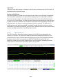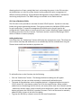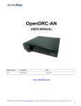
1
JSD-‐60 Manual Cinema Processor USL, Inc. 181 Bonetti Drive San Luis Obispo, CA 93401-‐7397 USA Phone: +1 805 549 0161 Fax: +1 805 549 0163 www.uslinc.com Page 2 One-‐Year Limited Warranty USL, Inc. warrants that each product manufactured by it will be free from defects in material and workmanship under normal usage for a period of one (1) year after its purchase new from an authorized dealer. Our obligation under this warranty is limited to repairing or replacing any product or component which we are satisfied does not conform to the foregoing warranty and which is returned to our factory, freight paid, or serviced by one of our authorized contractors. The foregoing warranty is exclusive and in lieu of all other warranties, whether expressed or implied. Such warranty shall not apply to any product or component (A) repaired or altered by anyone other than USL, Inc. or an authorized service contractor; (B) tampered with or altered in any way or subjected to misuse, negligence or accident or (C) which has been improperly connected installed or adjusted other than in accordance with USL, Inc.’s instruction. Page 3 Table of Contents 1. 2. 3. Safety Notice Legal Notices Regulatory Compliance 3.1 Declaration of Conformity 3.2 Equipment Class 3.3 Disposal and Recycling 4. System Version 5. System Overview 5.1 System Description 5.2 Block Diagrams 5.3 Model Numbers 6. Specifications 7. Installation 7.1 Initial Power Up 7.2 System Hardware Mounting, Grounding and Ventilation 7.3 Eight Channel Analog Output 7.4 AES/EBU Output Rear Panel Connections (JSD-‐60LS or JSD-‐60DS) 7.5 Eight Channel Analog Crossover Output (JSD-‐60LX or JSD-‐60DX) 7.6 BLU link Output Rear Panel Connections (JSD-‐60LN or JSD-‐60DN) 7.7 Audio Input Connections 7.8 Analog Audio Output Connections 7.9 Automation Interface 8. Graphical User Interface Configuration 8.1 GUI File Organization 8.2 GUI Installation 8.3 Set IP Utility 8.4 JSD-‐60 Configuration 8.5 File Management 8.6 Communications 8.7 Unit Settings 8.8 Main Fader 8.9 Front Panel View 8.10 Tabs 8.10.1 Summary Tab 8.10.2 Formats Tab 8.10.3 Equalizer Tab 8.10.4 Filters Tab 8.10.5 Crossovers Tab 8.10.6 Outputs Tab 8.10.7 BLU Link Tab 8.10.8 Global Tab 8.10.9 Advanced Tab Page 4 6 6 7 10 11 12 12 13 13 14 17 18 21 21 21 22 22 23 24 25 26 27 28 28 28 30 32 33 34 35 39 40 40 40 41 42 45 46 48 49 51 52 8.10.10 Software Update Tab 8.10.11 Logging Tab 8.10.12 Diagnostics Tab 8.11 Channel Crossover and Equalization Procedure 8.11.1 Crossover Adjustment 8.11.2 Auditorium Equalization 8.11.3 Automatic Equalization 8.11.4 Manual Equalization 8.11.5 LFE Equalization Procedure 9. System Operation 9.1 Front Panel 9.2 Automation 9.3 System Monitoring Appendix A – Connector Pin Outs Appendix B – Automation Commands Appendix C – System Restore and Power-‐Up Buttons Page 5 56 58 59 59 59 60 60 61 62 64 65 65 65 70 80 83 1. Safety Notice Safety Notices Review the following safety precautions to avoid injury and prevent damage to this product. To avoid potential risk, use this product only as specified and only for the purpose described in the instruction manual. To Avoid Fire and Personal Injury: • Use correct power cable. Use only the power cable provided. Ensure that the AC power outlet is located near the product and is easily accessible. • Use a correctly grounded power source. The power supply earth ground is established through the ground conductor in the power cable. To avoid the potential of electric shock, the ground conductor must be correct. • Observe source ratings. To avoid risk of fire or electric shock, the power source must be 100 – 240 VAC, 50 – 60 Hz. • Do not operate with suspected failures. If you suspect there is damage or malfunction with this product, call the factory. • Do not attempt repair. Only a trained factory service person is authorized to repair this product. • Do not operate this product near heat sources. This product should not be located near heat sources such as radiators, heat registers, or stoves. • Provide proper ventilation. The operating temperature range is between 0º C and 40º C. The humidity range is between 20% and 80%, non-‐condensing. The cooling method is convection. • Keep product surfaces clean and dry. Disconnect the power cable from the power source before cleaning. Do not use liquid cleaners or aerosol cleaners. Use a damp cloth for cleaning. • Do not push objects into openings of this product. Never insert objects into the product through openings. • Do not operate in wet or damp conditions. • Do not operate in an explosive atmosphere. • Inspect the power cable and all cables prior to use. Confirm that the power cable and other interconnecting cables are free from damage. 2. Legal Notices Manufactured under license from Dolby Laboratories®. Dolby® and the Double-‐D symbol are trademarks of Dolby Laboratories®. Manufactured under license under U.S. Patent Nos: 5,956,674; 5,974,380; 6,487,535 & other U.S. and worldwide patents issued & pending. DTS, the Symbol, & DTS and the Symbol together are registered trademarks & DTS Digital Surround and the DTS® logos are trademarks of DTS, Page 6 Inc. Product includes software. © DTS®, Inc. All Rights Reserved. The JSD-‐60 includes technology used under license from Harman International Industries. 3. Regulatory Compliance EN 60950-‐1 The EN 60950-‐1 standard specifies the safety design requirements that reduce or eliminate the risk of personal injury to both the product user and service personnel. This product is designed and tested to meet the standards of the International Electrotechnical Commission (IEC) European Norm EN 60950-‐1, IEC 60950-‐1 (the standard for information technology equipment including electrical business equipment). Le Résumé de la Sécurité general Européen Examinez les précautions de la sécurité suivantes éviter la blessure et prévenir le dégât à ce produit. Éviter le risque potentiel, utilisez ce produit seulement comme a spécifié et seulement car le but a décrit dans le manuel d’instructions. Éviter Feu et Blessure Personnelle • Utilisez le Câble du Pouvoir Correct. Utilisezseulement le câble du pouvoir fourni. Assurez que lesAC font fonctionner le débouché est localisé près leproduit et est accessible facilement. • Utilisez une Source du Pouvoir Correctement Fondée. • La terre du monde de la Provision du Pouvoir estétablie à travers le conducteur moulu dans le câble du pouvoir. Éviter le potentiel de choc électrique, leconducteur moulu doit être correct. • Observez des Estimations de la Source. Pour éviterrisque de feu ou choc électrique, la source du pouvoirdoit être 220-‐240 VAC 50 Hz. • N’opérez pas ce Produit avec Toutes Clôtures Ouvertes ou Enlevez. • Évitez l’Ensemble de circuits Exposé. N’entreprenez pas ouvrir la Provision du Pouvoir parce que sa certi-‐fication de la sécurité serait invalidée. La Provision du Pouvoir est un appareil scellé non-‐réparable. • N’opérez pas avec les Échecs Suspects. Si vous suspectez il y a le dégât ou mal fonctionner avec ce produit, appelez l’usine. • N’entreprenez pas Réparation. Seulement une personne du service de l’usine compétente est autorisée pour réparer ce produit. • N’opérez pas ce Produit Sources de la ChaleurProches. Ce produit ne devrait pas être localisé desources de la chaleur proches tel que radiateurs, registres de la chaleur, poêles, ou amplificateurs. • Fournissez Ventilation Adéquate. La température dufonctionnement devrait être entre 0° C et 40° C. • L’humidité devrait être 20% et 80%. La méthoderefroidissante est par convection et un ventilateur interne. • Gardez les Surfaces du Produit Nettoient et Sec. Page 7 • • • • • • • Déconnectez le câble du pouvoir de la source du pouvoir avant de nettoyer. N’utilisez pas de nettoyeurs. liquides ou de nettoyeurs de l’aérosol Utilisez un tissu humide pour nettoyer. Ne poussez pas d’Objets Dans Ouvrir de ce Produit. Jamais objets de l’encart dans le produit à travers ouvertures. N’opérez pas Dans les Conditions Mouillées ou humides. N’opérez pas Dans une Atmosphère Explosive. Prévenez le Répandre des Liquides sur les Composants du Système. Inspectez le câble du pouvoir et tous les câbles antérieur à usage. Confirmez que le câble du pouvoir et autres interconnectant câbles sont libres de dégât. Le Niveau de la sécurité L’EN 60065 niveau spécifie exigences du dessin de la sécurité qui réduisent ou éliminent le risque de blessure personnelle à l’utilisateur du produit et personnel du service. Ce produit est conçu et est testé pour satisfaire aux niveaux de l’Electrotechnical Commission Interna-‐tional (IEC) Norm Européen (EN) 60065 (Le Niveau pour Matériel de la Technologie de l’Information qui Inclut le Matériel de l’Affaire Électrique). Allgemeine Europäische Sicherheitszusammenfassung Beachten Sie die folgenden Sicherheishinweise um Verletzungen zu vermeiden und Schaden an diesem Produkt zu verhindern. Um potentielle Risiken zu vermeiden, benutzen Sie dieses Produkt nur wie beschrieben und nur für den in der Bedienungsanleitung identifizierten Zweck. Um Feuer und Verletzung zu vermeiden: • Benutzen Sie das korrekte Netzkabel. Nur das bereitgestellte Netzkabel soll benutzt werden. Stellen Sie sicher, daß die Wechselstromsteckdose in der Nähe des Produktes und leicht zugänglich ist. • Benutzen Sie eine korrekt geerdete Stromquelle. Die Erdung des Netzteils wird durch den Erdleiter im Stromkabel hergestellt. Um das elektrische Schockrisiko zu vermeiden muß der Erdleiter korrekt sein. • Beachten Sie die Nennwerte der Stromquelle. Um das Risiko von Feuer oder elektrischem Schock zu vermeiden muß eine 100-‐240 VAC 50-‐60 Hz Stromquelle benutzt werden. • Betreiben Sie das Gerät nicht wenn Fehlerverdacht besteht. Wenn Sie vermuten, daß das Gerät defekt oder beschädigt ist, kontaktieren Sie den Hersteller. • Versuchen Sie keine Reparatur. Nur ein vom Hersteller ausgebildeter Servicetechniker ist befugt dieses Produkt zu reparieren. • Betreiben Sie dieses Produkt nicht in der Nähe von Wärmequellen. Dieses Produkt sollte nicht in die Nähe von Wärmequellen, wie zum Beispiel Heizungen, Herden und Warmluftöffnungen gestellt werden. • Erlauben Sie für ausreichende Belüftung. Die Betriebstemperatur sollte zwischen 0° C und 40° C sein, die Luftfeuchtigkeit sollte 20% bis 80% nicht kondensierend, betragen. Luftzufuhr erfolgt durch Umluft und ein internes Gebläse. Page 8 • • • • • • • • Halten Sie die Produktoberflächen sauber und trocken. Ziehen Sie das Netzkabel aus der Steckdose vor der Reinigung. Benutzen Sie keine flüssigen oder Druckluft Reiningungsmittel. Benutzen Sie ein feuchtes Tuch zum Reinigen. Schieben Sie keine Gegenstände In die Öffnungen dieses Produktes. Betreiben Sie dieses Produkt nicht in nassen oder feuchten Bereichen. Betreiben Sie dieses Produkt nicht in explosiven Bereichen. Inspizieren Sie das Netzkabel und all anderen Kabel vor Benutzung. Bestätigen Sie, daß das Netzkabel und andere Kabel unbeschädigt sind. Betreiben Sie dieses Produkt nicht wenn es geöffnet oder Abdeckungen entfernt worden sind. Vermeiden Sie ungeschützte Schaltkreise. Öffnen Sie das Netzteil nicht, da sonst die Sicherheitszulassung ungültig würde. Das Netzteil ist ein unreparierbares luftdicht verschlossenes Gerät. Verhindern Sie das Verschütten von Flüssigkeiten auf die Systembestandteile. Sicherheit-‐Standard Der EN 60950-‐1 Standard spezifiziert die Sicherheitsanforderungen an das Design, um das Verletzungsrisiko von Endbenutzern und Servicepersonal zu reduzieren oder eliminieren. Dieses Produkt ist entwickelt und geprüft, um die Bedingungen der Europäischen Norm EN 60950-‐1, IEC 60950-‐1 (Einrichtungen der Informationstechnik -‐ Sicherheit) der Internationalen Elektrotechnischen Kommission (IEC) zu erfüllen. Page 9 3.1 DECLARATION OF CONFORMITY Page 10 The JSD-‐60 meets the intent of Directive 89/336/EEC for Electromagnetic Compatibility and Low Voltage Directive 73/23/EEC for Product Safety. Compliance was demonstrated to the following specifications as listed in the Official Journal of the European Communities: EN 55022: 2006 Conducted and Radiated Emissions • Conducted Emissions • Radiated Emissions, Class A Limits EN 55024: 1998 + A1: 2001 & A2: 2003 Immunity • Electrostatic Discharge Immunity • RF Electromagnetic Field Immunity • Power Line Surge Immunity • Conducted RF immunity • Power Frequency Magnetic Field Susceptibility • Voltage Dips, Short Interruptions and Variations • EN 61000-‐3-‐3: 1995 +A1: 2001 & A2: 2005 Voltage Fluctuation and Flicker FCC Part 15, Subpart B This equipment has been tested and found to comply with the limits for a Class A digital device, pursuant to part 15 of the FCC Rules. These limits are designed to provide reasonable protection against harmful interference when the equipment is operated in a commercial environment. This equipment generates, uses, and can radiate radio frequency energy and, if not installed and used in accordance with the instruction manual, may cause harmful interference to radio communications. Operation of this equipment in a residential area is likely to cause harmful interference in which case the user will be required to correct the interference at user’s own expense. Certifications • Low Voltage Directive 73/23/EEC. • EN 60950 Information Technology, Video, and similar Electronic Apparatus. • IEC 60950 Safety Requirements. • CE, UL, cUL Safety and Overall Compliance. • VDE Certified Power Cords. • Pollution: Not intended for environments where conductive pollutants may be present. 3.2 EQUIPMENT CLASS Type A: Equipment that is intended for connection to the building power supply wiring via nonindustrial plugs and sockets or via appliance couplers, or both. Page 11 3.3 DISPOSAL AND RECYCLING Wheelie-‐Bin Symbol The Wheelie-‐Bin symbol is attached to this product in compliance with the EU Directive 2002/96/EC on Waste Electrical and Electronic Equipment (WEEE). Its purpose is to deter the improper disposal of this product and to promote reuse and recycling. Proper Disposal In conformance with the Directive, at end of life this product should be either sent to an appropriate recycling facility for disassembly and recycling or returned to the supplier. Under no circumstances should this product be deposited in a landfill for disposal. Hazards of Noncompliance Electrical and electronic products may contain chemicals which can leach into the groundwater and cause health concerns through contaminated drinking water. Failure to dispose of this product in compliance with the WEEE Directive may result in penalties as determined by local ordinance. Please contact your dealer or USL, Inc., with questions regarding the proper disposal of this or any other USL product. USL, Inc. contact information: USL, Inc., 181 Bonetti Drive, San Luis Obispo, CA 93401-‐7397, USA. Phone: +1 805 549 0161 Fax: +1 805 549 0163 www.uslinc.com 4. System Version The JSD-‐60 is continuously being improved. New features are added through software/firmware updates and replacement of plug-‐in modules. This manual describes the JSD-‐60 versions available at this writing. Firmware/software versions for the systems described in this manual are listed in the table below: Component Version Graphical User Interface 2.1.1.25754 (GUI) Main PIC 141208 Bootloader 141205 DSP 141014 Front Panel 140811 Page 12 5. System Overview 5.1 SYSTEM DESCRIPTION The JSD-‐60 cinema sound processor is specially designed for digital cinema applications. Low noise and low distortion 96 kHz processing ensures superb presentations. In addition to the six standard formats. A user-‐configurable format button can be configured to support a variety of existing and future formats. It may also be used to duplicate an existing format but at a different fader level to simplify desired volume changes between content types. The front panel display shows the current fader level, the format name (which is user configurable), and the audio level on each audio output. The built-‐in bypass audio circuitry ensures that the presentation goes on in the unlikely event of a system failure. The JSD-‐60 is “automation friendly.” It features the standard DB25 parallel automation interface, an RS-‐232 (EIA232) interface, and Ethernet. The Ethernet interface accepts 5 simultaneous TCP connections to allow control by a digital cinema server and other equipment while simultaneously being monitored over another TCP connection. The Graphical User Interface runs on Windows XP®, Windows 7®, and Windows 8® operating systems. It allows for complete system configuration, monitoring, and firmware updates over USB, Ethernet, or RS-‐232. The JSD-‐60 graphical user interface simplifies installation by including sound pressure level measurement and automatic equalization. System monitoring, control, and firmware update functions are also available on a standard web browser. The JSD-‐60 includes a precision 1/3 octave RTA that uses the filters specified in ANSI S1.11-‐ 1986. The JSD-‐60 also does sound pressure measurements using the C-‐weighted filter specified in ANSI S1.4-‐1983. The RTA and SPL meter can be used to equalize an auditorium manually or automatically. The JSD-‐60 includes an automatic equalization feature (auto-‐EQ). Auto-‐EQ uses user-‐defined microphone calibration files and standard or user-‐defined equalization curves to automatically adjust the graphic equalizer on each channel. The JSD-‐60 is also “diagnostic friendly.” The system logs the last 15,000 events (format changes, level changes, internal temperature, loss of AES/EBU audio, etc.) to internal flash memory. Log data can be reviewed on the GUI or the web interface. Current operational status, including selected format, fader level, and measured audio output levels, is available on the GUI and on the web interface. The current status of the system is also available over SNMP (Simple Network Management Protocol). An optional plug-‐in module decodes Dolby Digital® and DTS® encoded content. The HI and VI-‐N outputs are configurable on a per-‐format basis. Page 13 An optional crossover card supports biamp of three screen channels and provides two LFE outputs. An optional AES/EBU output card provides 12 channels of AES/EBU. The AES/EBU outputs are on two RJ45 connectors and provide full range or biamp screen channels plus the surround channels and two LFE outputs. An optional BLU link output card provides 12 channels on a Harman BLU link loop. The BLU link loop is driven by two RJ45 connectors and provides full range or biamp screen channels plus the surround channels and two LFE outputs. Note that the JSD-‐60 is the BLU link loop clock master and runs the loop at 96kHz. A user configurable mixer routes audio as required for the specific auditorium. Supported auditorium configurations include 5.1, 7.1DS, 7.1SDDS, and drive-‐in. 5.2 BLOCK DIAGRAMS The following simplified block diagrams assist the user in understanding the signal flow within the JSD-‐60. All input sources are routed to the Input Mixer that routes a source to an output. An internal noise and tone generator is available for testing and acoustic calibration of the sound system. The output stream contains the main fader, sync and surrounds delays, equalizer, channel filter, and crossover with individual band delays and gain settings. The hearing impaired (HI) and visually impaired -‐ narrative (VI-‐N) outputs do not include an equalizer, channel filter or crossover and are not affected by the main fader. Page 14 Figure 5.2a Audio Processing Overview The output of the mixer or internal generator is routed to the main fader control. The output is then routed to a delay for both projector synchronization and surrounds. The crossover includes individual delays for high and low bands. Each channel, with the exception of LFE, HI, and VI-‐N, has a 27 band graphic equalizer including bass and treble shelving filters. After equalization a channel filter process can be applied. The channel filter can be used to apply special effects to a specific channel. For example, it may be desirable to notch out dialog frequencies on a generated Lc or Rc channel. The channel filter supports high pass, low pass, band pass, notch, and disabled. The LFE channel is routed through a parametric equalizer and a 125Hz low pass filter as specified by SMPTE EG0432-‐2-‐2006. When the internal crossover is not used, full-‐range audio is sent to the low-‐band outputs. The outputs are driven with balanced line drivers through solid state switches used for muting. Similar switches route bypass audio to the left and right outputs when required. When the AES/EBU or BLU link output module is used, the output trim controls are moved to the DSP since there is no analog output circuitry. As shown in Figure 5.2b, each input is digitally converted (analog to digital or sample rate conversion) and routed to the mixer within the DSP. The two channel sources are converted and then routed to a Sample Rate Converter (SRC) that can be either mixed or have an active matrix applied to them to generate six digital audio sources (5.1 channels). The COAX and TOSLINK sources can have either a two channel mix or six channel decode. The optional DI-‐84 board is required to decode Dolby Digital ®, DTS®, or apply an active matrix, each converting the two channel signals to 5.1 channels. Page 15 Figure 5.2b Audio Sources Overview including optional DI-‐84. Each output, including HI and VI-‐N, has a mixer with eight digital and six analog inputs. The input source and decode options determine the active sources for the mixer. Simplified Crossover Block Diagram The following Figure 5.2c shows the details of the crossovers. The audio is split into high band and low band components with high pass filter #4 and low pass filter #0. These are both 4th order Linkwitz-‐Riley filters. They are followed by a series of parametric filters. The high band includes a pair of shelving filters (#7 and #8) to compensate for the high frequency characteristics of the high frequency horn and the screen. Each band ends up with a delay Page 16 block. Individual band delays can be set as required. This block also includes a provision to flip the phase in case a speaker is wired incorrectly. In most installations, the user merely loads crossover settings from the supplied speaker library, and then adjusts the output trims as required to compensate for amplifier gain differences and speaker efficiency differences. Figure 5.2c Crossover Overview In the lower portion of Figure 5.2c, the LFE band is shown. It is not really a crossover since it does not split the channel into multiple frequency bands. It is similar to a crossover, however, in that a single audio channel is split into multiple outputs with separate equalization (parametric) and delay. Because of this similarity, the LFE equalizer is located in the crossover section of the DSP. The additional LFE2 output is available from the optional crossover board’s output connector, the optional AES/EBU outputs, or the optional BLU link output. 5.3 MODEL NUMBERS An optional output board is part of the unit’s assembly that supports a variety of output configurations. These are listed in the table below. The various JSD-‐60 options are identified by model number suffixes as shown in the tables below. The first letter identifies input options such as the presence or absence of Dolby Digital® and DTS® decoding. The second letter indicates the type of output. Note that all units have analog HI/VI-‐N in addition to the outputs listed in the tables below. First Suffix Description USL Module Part Letter Number L 8 channel AES/EBU input, no Dolby Digital® or DTS® N/A decode D 8 channel AES/EBU input, Dolby Digital® and DTS® DI-‐84 Page 17 decode for alternative content Second Suffix Letter None N S X Description 8 channel analog output BLU link output AES/EBU output 8 channel analog output with biamp for 3 screen channels and two LFE outputs USL Module Part Number N/A JSDN-‐60 JSDS-‐60 XTD-‐60 A JSD-‐60DX has 8 AES/EBU input channels, Dolby Digital® and DTS® decoding for alternative content with biamp analog outputs. 6. Specifications Features A processor specially designed for Digital Cinema applications. Low noise and low distortion processing ensures superb presentations. In addition to six standard formats, the JSD-‐60 offers a fully configurable optional format to address such details as audio level changes and 3 or 5 stage channels. Built-‐in bypass audio circuitry ensures that the presentation goes on. Audio Inputs • PA/Cal Microphone – XLR and ¼”, 0.7mV sensitivity. Switchable phantom power: 12V balanced, 9V unbalanced, or off. • Non-‐Sync analog input – RCA 75mV to 4.775V. • Six Channel analog input – DB25F 300mV. • COAX – RCA: PCM with optional Dolby Digital® and DTS® decoding. • TOSLINK – Optical PCM with optional Dolby Digital® and DTS® decoding. • AES/EBU – 8 Channel 48-‐96KHz sample rates. Analog Audio Outputs – Accessibility • Hearing Impaired – User selectable input channel mix. 300mV mono balanced. • Visually Impaired -‐ Narrative– User selectable input channel mix. 300 mV mono balanced. Eight Channel Analog Audio Outputs (JSD-‐60L and JSD-‐60D) Eight Channels Balanced 300mV adjustable (L, C, R, Ls, Rs, LFE, Lc/Lrs, Rc/Rrs). Eight Channel Biamp Analog Audio Outputs (JSD-‐60LX and JSD-‐60DX) • 12 outputs, Balanced 300mV adjustable. Configurable as 5.1, 7.1 broadband, or biamp three screen channels. Eight Channel Biamp AES/EBU Audio Outputs (JSD-‐60LS and JSD-‐60DS) Page 18 12 outputs, on 6 AES/EBU pairs on two RJ45 connectors. 96kHz sample rate. Configurable as 5.1, 7.1 broadband, or biamp three screen channels. Eight Channel Biamp BLU link Audio Outputs (JSD-‐60LN and JSD-‐60DN) • 12 outputs, on two RJ45 connectors. 96kHz sample rate. Configurable as 5.1, 7.1 broadband, or biamp three screen channels. Communication Ports • DB25F pulse automation. • Serial control – RS-‐232. • USB for laptop setup. • Ethernet 10/100 -‐ RJ45. Front Panel Interface • Eight buttons: COAX, TOSLINK, DIGITAL 8 CH, OPTION, ANALOG 6 CH, NON/SYNC, MIC, and MUTE. • Main Fader – 0-‐10 used for main audio and bypass audio. • Front panel displays fader level and selected format. Bar graph displays output levels including high and low bands when operating in biamp. • USB connector. • Power switch and power supply status LEDs. Turning power off activates bypass mode. Format Selection • Digital (COAX, TOSLINK, 8 Channel AES/EBU). • Analog (6 channel, Non-‐Sync, and Microphone). • Option (Configurable in software, e.g., digital 8 channel, COAX, TOSLINK, analog 6 channel, Non/Sync, and microphone). Rear Panel Connectors – Main Chassis • PA/Calibration Microphone – XLR / ¼” phone jack. • Six Channel Analog – DB25F. • Non/Sync – two RCA jacks. • Hearing Impaired and Visually Impaired -‐ Narrative – pluggable Phoenix connector. • COAX – RCA jack with transformer input • TOSLINK – Optical. • 8 Channel Digital AES/EBU – DB25F and RJ45. • Removable Memory Card – SD compatible. • Serial Control – RS-‐232 on DB9F. • Pulse Automation – DB25F. • 10/100M Ethernet – RJ45. • DC 12V Power Connector – 5mm with 2.5mm pin. • AC Power – IEC socket. 100-‐240VAC, 50/60Hz, 18W typical. • Page 19 • • • • Eight Channel Audio Output -‐ DB25M. Eight balanced outputs for full range or low band (if crossover option installed). Crossover Audio Output -‐ DB25M (crossover option only). Balanced outputs for left, center, and right high band plus LFE2. AES/EBU Audio Output – Two RJ45 connectors (AES/EBU output option only). Six AES/EBU pairs: left low, left high, center low, center high, right low, right high, Ls, Rs, Lrs, Rrs, LFE, LFE2. When biamp mode not selected, low band outputs become full range. BLU link Audio Output – Two RJ45 connectors (BLU link option only). Drives 96kHz BLU link loop as master providing left low, left high, center low, center high, right low, right high, Ls, Rs, Lrs, Rrs, LFE, LFE2. When biamp mode not selected, low band outputs become full range. Processing • 96 kHz processing. • One-‐third octave equalization on all channels except LFE, HI, and VI-‐N. • Parametric equalizers on LFE. • Synchronization delays for all inputs. • Surround delays for all surround channels. • Optional Internal crossovers. Crossovers support biamp with 3 screen channels plus individual parametric equalization and two LFE outputs. Crossover includes a speaker library and allows for user defined speaker systems. Bypass Mode In an emergency situation, the JSD-‐60 can be switched off, automatically enabling the bypass circuitry. Front panel buttons, LEDs, display, and fader will still function, allowing the operation of the unit in various analog and digital formats. Final output is a monophonic signal fed to the left and right channels. Bypass circuitry only drives analog outputs, not AES/EBU or BLU link outputs. Note: The 12 VDC bypass power supply must be connected for this functionality. Graphical User Interface The JSD-‐60 Graphical User Interface (GUI) operates under Windows XP, Windows 7, and Windows 8. It communicates with one or more JSD-‐60 systems simultaneously over USB, Ethernet, or RS232. The GUI is used for system configuration including auditorium equalization (both manual and automatic equalization). Dynamic Range: Typically 105dB. Power Requirements: 100-‐240VAC, 50/60Hz, 30 watts maximum (18 watts typical). Dimensions: Standard 1U rack-‐mount chassis. Agency Approvals: UL, cUL, CE and FCC. Page 20 7. Installation 7.1 INITIAL POWER UP A quick power-‐up test of the JSD-‐60 is suggested before mounting it in the equipment rack and wiring it up. This test can quickly detect shipping or other damage. • Turn the AC power switch to the off position. • Using the supplied AC line cord or one appropriate for the installation location (the power supply is a universal input supply 100-‐240 VAC, 50/60 Hz), connect the JSD-‐60 to the AC line. • Connect the supplied 12 VDC bypass power supply to the bypass power input on the rear panel of the JSD-‐60 and plug it in to the AC line. The front panel “Bypass Mode” LED should flash, the bypass power LED should light, and one of the format buttons should light. • Press each of the format buttons and the mute button, one after another. The appropriate button should light. • Rotate the fader in each direction and verify that the fader level on the display changes. • Turn on the AC power switch. All the green power LEDs on the bottom right of the front panel should light. The “Bypass Mode” LED should stop flashing. • Press each of the format buttons and the mute button, one after another. The appropriate button should light and the display should show the selected format. Note that the format button LEDs for digital formats will flash when no digital input is provided. • Press the mute button verifying that its LED toggles each time the button is pressed. • Rotate the fader in each direction verifying that the fader numbers on the display change 7.2 SYSTEM HARDWARE MOUNTING, GROUNDING AND VENTILATION The JSD-‐60 is designed to mount in a standard 19 inch (482.6mm) rack and is one rack unit high (1.75 inches, 44.45mm). The JSD-‐60 should be mounted at “eye level” in the equipment rack for optimum display contrast and visibility. We recommend vented panels (USL part number VP-‐1) above and below the JSD-‐60 whenever space permits. Mounting the unit immediately above a major heat-‐producing component, such as a power amplifier, is not recommended. Equipment mounted immediately above the JSD-‐60 should not be more than 9 inches (225mm) deep to ensure adequate airflow through the top cover ventilation holes on the JSD-‐60. The JSD-‐60 includes a three-‐prong grounding plug and a three-‐wire power cord to accommodate a safe ground path from the chassis to the electrical system ground. Defeating this ground by removing the ground prong is not recommended. Page 21 7.3 EIGHT CHANNEL ANALOG OUTPUT 1. Power entry Module – Accepts IEC-‐type line cord from 100-‐240VAC power source. Also contains a 500mA Slo-‐Blow 5x20mm fuse. 2. Bypass Power Supply – 12VDC at 1.25A. 3. RS-‐232 on a DE9F connector for communications with GUI or automation. 4. SD Card – Stores a backup copy of unit configuration. Can also be used to transfer settings to another unit or read by the GUI to download to a connected unit. 5. AES/EBU input connector (RJ45) – parallel connections to the DB25F to the right. 6. Ethernet connector (RJ45) – Network communications with GUI, web browsers, automation, etc. 7. AES/EBU input connector (DB25F) – Eight channels, DMA8 pin out. 8. Automation DB25F Connector – Receives automation pulses from other system components. Ten Control input lines with ground and 5V power provided to support a standard pulse to ground system. The 5V output can power a JSDV-‐80 remote volume control that pulses control lines 9 and 10. 9. COAX -‐ RCA connector for S/PDIF PCM or optional DTS® and Dolby Digital® decoding. 10. TOSLINK Port – Optical Fiber input (PCM) with optional DTS® and Dolby Digital® decoding. 11. Hearing Impaired/VisuallyImpaired-‐Narrative outputs. 12. Eight Channel Analog output provides six fixed outputs (L, C, R, LFE, Ls, Rs) and two that can be set up as either Lc/Rc or Lrs/Rrs. Other output configurations, such as drive in, are supported. 13. Six Channel Analog Input on DB25F – Balanced line inputs. 14. Non Sync (N/S) connectors – L and R analog inputs, RCA type connectors. 15. Public Address and Real Time Analyzer microphone phantom power supply selector, 12V balanced, 9V unbalanced, and off. 16. Public Address and Real Time Analyzer microphone – XLR and ¼” stereo jack with configurable phantom power. 7.4 AES/EBU OUTPUT REAR PANEL CONNECTIONS (JSD-‐60LS OR JSD-‐60DS) Page 22 1. Power entry Module – Accepts IEC-‐type line cord from 100-‐240VAC power source. Also contains a 500mA Slo-‐Blow 5x20mm fuse. 2. Bypass Power Supply – 12VDC at 1.25A. 3. RS-‐232 on a DE9F connector for communications with GUI or automation. 4. SD Card – Stores a backup copy of unit configuration. Can also be used to transfer settings to another unit or read by the GUI to download to a connected unit. 5. AES/EBU input connector (Top RJ45) – parallel connections to the DB25F to the right. Ethernet connector (Bottom RJ45) – Network communications with GUI, web browsers, automation, etc. 6. AES/EBU input connector (DB25F) – Eight channels, DMA8 pin out. 7. Automation DB25F Connector – Receives automation pulses from other system components. Ten Control input lines with ground and 5V power provided to support a standard pulse to ground system. The 5V output can power a JSDV-‐80 remote volume control that pulses control lines 9 and 10. 8. COAX -‐ RCA type connector (PCM) with optional DTS® and Dolby Digital® decoding. 9. AES/EBU Outputs 1-‐8 10. TOSLINK Port – Optical Fiber input (PCM) with optional DTS® and Dolby Digital® decoding. 11. Hearing Impaired/Visually Impaired-‐Narrative outputs. 12. AES/EBU Outputs 9-‐12 13. Eight channel analog outputs. These outputs are active whether the AES/EBU output card is present or not. If the JSD-‐60 is configured for biamp, the screen channel outputs will be the low band. 14. Six channel analog input on DB25F – Balanced line inputs. 15. Non Sync (N/S) connectors – L and R analog inputs, RCA type connectors. 16. Public Address and Real Time Analyzer microphone phantom power supply selector, 12V balanced, 9V unbalanced, and off. 17. Public Address and Real Time Analyzer microphone – XLR and ¼” stereo jack with configurable phantom power. 7.5 EIGHT CHANNEL ANALOG CROSSOVER OUTPUT (JSD-‐60LX OR JSD-‐60DX) 1 2 3 4 5 6 7 8 9 10 11 12 13 14 15 16 17 18 19 1. Power entry Module – Accepts IEC-‐type line cord from 100-‐240VAC power source. Also contains a 500mA Slo-‐Blow 5x20mm fuse. 2. Bypass Power Supply – 12VDC at 1.25A. 3. RS-‐232 on a DE9F connector for communications with GUI or automation. 4. SD Card – Stores a backup copy of unit configuration. Can also be used to transfer settings to another unit or read by the GUI to download to a connected unit. Page 23 5. AES/EBU input connector (RJ45) – parallel connections to the DB25F to the right. 6. Ethernet connector (RJ45) – Network communications with GUI, web browsers, automation, etc. 7. AES/EBU input connector (DB25F) – Eight channels, DMA8 pin out. 8. Automation DB25F Connector – Receives automation pulses from other system components. Ten Control input lines with ground and 5V power provided to support a standard pulse to ground system. The 5V output can power a JSDV-‐80 remote volume control that pulses control lines 9 and 10. 9. Crossover bypass output levels for high and low bands. 10. COAX -‐ RCA type connector (PCM) with optional DTS® and Dolby Digital® decoding. 11. Crossover balanced stage high band (L, C, R) and LFE 2 outputs. 12. TOSLINK Port – Optical Fiber input (PCM) with optional DTS® and Dolby Digital® decoding. 13. Crossover bypass frequency and mode selection switches. 14. Hearing Impaired/Visually Impaired-‐Narrative outputs. 15. Eight channel analog outputs. Low band on screen channels, full range on surround channels. 16. Six channel analog input on DB25F – Balanced line inputs. 17. Non Sync (N/S) connectors – L and R analog inputs, RCA type connectors. 18. Public Address and Real Time Analyzer microphone phantom power supply selector, 12V balanced, 9V unbalanced, and off. 19. Public Address and Real Time Analyzer microphone – XLR and ¼” stereo jack with configurable phantom power. 7.6 BLU LINK OUTPUT REAR PANEL CONNECTIONS (JSD-‐60LN OR JSD-‐60DN) 1. Power entry Module – Accepts IEC-‐type line cord from 100-‐240VAC power source. Also contains a 500mA Slo-‐Blow 5x20mm fuse. 2. Bypass Power Supply – 12VDC at 1.25A. 3. RS-‐232 on a DE9F connector for communications with GUI or automation. 4. SD Card – Stores a backup copy of unit configuration. Can also be used to transfer settings to another unit or read by the GUI to download to a connected unit. 5. AES/EBU input connector (Top RJ45) – parallel connections to the DB25F to the right. Ethernet connector (Bottom RJ45) – Network communications with GUI, web browsers, automation, etc. 6. AES/EBU input connector (DB25F) – Eight channels, DMA8 pin out. 7. Automation DB25F Connector – Receives automation pulses from other system components. Ten Control input lines with ground and 5V power provided to support a Page 24 standard pulse to to ground system. The 5V output can power a JSDV-‐80 remote volume control that pulses control lines 9 and 10. 8. Monitor analog output – Balanced analog audio of a user selected BLU link channel. 9. COAX -‐ RCA type connector (PCM) with optional DTS® and Dolby Digital® decoding. 10. BLU link output connector – Drives the input of the next device in the BLU link loop. 11. TOSLINK Port – Optical Fiber input (PCM) with optional DTS® and Dolby Digital® decoding. 12. Hearing Impaired/Visually Impaired-‐Narrative outputs. 13. BLU link input connector – Driven by the output of the previous device in the BLU link loop. 14. Eight channel analog outputs. Low band on screen channels, full range on surround channels. 15. Six channel analog input on DB25F – Balanced line inputs. 16. Non Sync (N/S) connectors – L and R analog inputs, RCA type connectors. 17. Public Address and Real Time Analyzer microphone phantom power supply selector, 12V balanced, 9V unbalanced, and off. 18. Public Address and Real Time Analyzer microphone – XLR and ¼” stereo jack with configurable phantom power. 7.7 AUDIO INPUT CONNECTIONS Eight Channel AES/EBU Input The JSD-‐60 accepts 8 channel AES/EBU audio. This input is typically driven by the digital cinema server (DCS). The JSD-‐60 includes a DB25F connector using the Dolby® DMA8 pin out and an RJ-‐ 45 connectors using the StudioHub[2] pin out. The first six channels are assigned speakers by industry convention. The remaining channels can be configured by the user (i.e., sources for HI/VI-‐N, Lrs, Rrs, etc.). For convenience, all connector pin outs are listed in Appendix A. Six Channel Analog Input The JSD-‐60 six channel analog input is on a DB25F connector. The analog inputs are active balanced (differential) inputs. They may be driven by balanced or unbalanced sources. When driven by an unbalanced source, the negative input should be connected to the low side of the source at the source equipment to minimize ground loop noise. The cable should be twisted pair with individual shields, even when driven by an unbalanced source. The DB25F connector uses the THX® pin out as specified in the table in Appendix A. Two Channel Analog Input The JSD-‐60 has a stereo analog input (Non/Sync) on two RCA connectors. Connect these to an appropriate source using RCA cables. Various stereo decode methods are available in the system. These allow direct driving of the left and right speakers, adding a synthesized center channel, surround, and custom mix for all output channels. [2] Please see the Studio Hub website: www.StudioHub.com Page 25 Two Channel Digital Inputs The JSD-‐60 has an S/PDIF input and a TOSLINK input. • S/PDIF Input. A stereo digital input on an RCA connector marked COAX. It is a standard S/PDIF (Sony Philips Digital Interface) input. Connect to appropriate sources with 75 ohm coaxial cable with RCA connectors on each end. As with the other stereo inputs, various decode methods are available. • TOSLINK Input. A TOSLINK optical digital stereo input is included on the JSD-‐60. Connect this input to an appropriate source with a standard TOSLINK cable. As with other stereo inputs, various decode methods are available. Single Channel Audio Inputs The JSD-‐60 has a Public Address (PA) and Real Time Analyzer (RTA) microphone input. • PA/RTA Microphone Input. Plug a PA microphone in to the combination XLR / ¼” stereo (TRS) phone jack. The microphone input may be configured to drive the main or the surround speakers. In addition, the PA microphone input can drive the RTA for room equalization. The jack is a combination XLR and ¼” TRS (stereo) connector. The XLR input is balanced. The 1/4 inch connector can be used either balanced or unbalanced. Phantom power can drive both sides of a balanced line with +12V through 1k on each line. It can also drive an unbalanced input (typically on the 1/4 inch connector) with +9V through 1.8k. When using unbalanced phantom power, the signal is on the tip and the phantom power voltage is on the ring. The phantom power is designed to provide low current bias to electret microphones. Condensor microphone preamps may draw more current than the phantom power can supply. 7.8 ANALOG AUDIO OUTPUT CONNECTIONS The JSD-‐60 provides eight main channel outputs plus HI and VI-‐N outputs. All outputs are balanced and may drive balanced or unbalanced loads. When driving unbalanced loads, run two conductor shielded cable and connect the “ – ” terminal of the JSD-‐60 output to the low side of the unbalanced load at the load instead of at the JSD-‐60 to minimize ground loop noise. Main Audio Outputs The eight channel analog output connector provides eight balanced analog outputs. These are full-‐range outputs if no crossover board is installed. If a crossover board is installed, this connector provides the low band outputs of the screen channels, the full range surround channels, and the LFE1 output. The crossover output connector provides three crossover high band outputs plus the LFE2 output. On systems with the crossover, four DIP switches set the crossover frequency for the bypass passive crossover. If the crossover is not to be used, set all the switches to off. Adjust the low trim pot to yield the desired bypass output level. Remember that the front panel fader also affects the output level when in bypass. For more information on Page 26 bypass operation with crossovers, see Section 8.11.1. The connector pin outs are listed in Appendix A HI/VI-‐N Outputs The JSD-‐60 has balanced HI and VI-‐N outputs that can drive balanced or unbalanced loads. As with other outputs, the use of twisted pair shielded cable is suggested whether the load is balanced or unbalanced. When driving an unbalanced load, connect the “ – ” output of the JSD-‐ 60 to low side of the unbalanced input at the destination end of the cable to minimize ground loop noise. The source of audio to drive the HI and VI-‐N outputs is configurable on a per-‐format basis. The VI-‐N audio output is typically driven by AES/EBU input 8. The HI audio output can be driven from AES/EBU input 7 or from an audio mix via the channel mixer located in the “Advanced” tab in the Windows GUI. Note that since the JSD-‐60 has only 8 channels of AES/EBU, the HI/VI-‐N tracks in a DCP cannot be used by the JSD-‐60 in a 7.1DS auditorium. In such auditoriums, the LCR mix is generally used and a USL DAX-‐202 is used to convert AES/EBU VI-‐N from the media block output to analog to drive the HI/VI system. 7.9 AUTOMATION INTERFACE The JSD-‐60 includes the traditional parallel automation interface plus RS-‐232 and Ethernet. This interface will accept the JSD-‐100 automation commands to simplify the installation and setup. Parallel Interface Pins 1 through 10 of the DB25F automation connector are “control” pins that accept contact closure or open collector pulses to ground to select formats and to control the main fader. To change the selected format, the corresponding pin, 1 through 7 is pulsed. Pulsing pin 8 low toggles the mute state. Pins 1 through 10 are internally pulled up to +8.4V. They each source 400uA when grounded. An automation input control pin needs to be pulled below 2.6V for 50ms or more for the JSD-‐60 to recognize it as low. A +5V at 100mA is available on pin 13 to drive an external remote fader control (JSDV-‐80). Pin 12 is the “automation return.” Use this as the low side of switches and indicators instead of using chassis ground. It is ground through a 10 ohm resistor to limit ground loop current. RS-‐232 Interface The RS-‐232 interface appears on a DE9F connector on the rear panel. The connector is wired as a DCE device. A command interpreter accepts ASCII commands (described in Appendix B) over the RS-‐232 and Ethernet interfaces. The RS-‐232 port operates at 38.4kbps, 8N1 (8 data bits, no parity, 1 stop bit), no handshake. RTS/CTS and DTR/DSR are looped back. Ethernet Interface The JSD-‐60 includes a standard 10/100Mbps Ethernet interface. The same automation commands (described in Appendix B) are available on TCP connections to port 10001 on the Ethernet interface. The JSD-‐60 accepts up to 5 simultaneous TCP connections, allowing multiple control and monitor devices to be used. The Ethernet interface also includes a web Page 27 server. System status and basic control are available on internally generated web pages. System status is also available over SNMP. The JSD-‐60 also includes a Network Time Protocol (NTP) client that can be used to keep the internal real time clock accurate. Use a CAT5 or better Ethernet cable to connect the JSD-‐60 to the control network. 8. Graphical User Interface Configuration System Configuration using the Graphical User Interface The graphical user interface (GUI) allows for configuration and monitoring of the JSD-‐60. When installed, the JSD-‐60 GUI programs item and a desktop shortcut are created. The application is located in the c:\Programs (x86)\USL\JSD-‐60 Cinema Processor folder. The JSD-‐60 SetIP utility, User Manual, and DPInst64 USB driver are located in this folder. 8.1 GUI FILE ORGANIZATION The GUI installer places the executable program files in the Programs (x86) \USL\JSD-‐60 directory. Configuration files are placed in Documents\USL\JSD-‐60 as shown. • • • The EQ Curves directory holds data for generating limit curves for the RTA and automatic equalization. Standard curve data for several auditorium sizes are provided. Since these are plain text files, custom limit curves can be easily created. The Microphone Library holds calibration data on microphones used on the RTA. A separate file can be created for each microphone used with the system. The file includes the required preamp gain and frequency response adjustment. The Speaker Library holds crossover configuration files for a wide range of biamp speaker systems. These are also text files, so appropriate crossover settings for additional speaker systems can be created using a text editor such as Note Pad. See Appendix E for configuration file formats. 8.2 GUI INSTALLATION The GUI runs under Windows® XP, Windows® 7, or Windows® 8 operating systems. Insert the supplied CD and follow the on-‐screen instructions. Note: The USB driver needs to be installed after the GUI is installed. Follow the USB Driver Installation instructions. Page 28 Note: Windows XP installs a driver for a particular USB port and when connected to a different port, the user must repeat the installation process. We suggest executing the install process on all USB ports. USB Driver Installation The JSD-‐60 uses a native Windows USB System (winusb.sys) driver that is part of the operating system’s installation package. The driver is installed by using a co-‐installer that specifies that it will be working with the JSD-‐60. Installation with Windows 8, requires setting the start up to run with “Driver Signature Enforcement Disabled.” The JSD-‐60 Installation (Setup) program creates a subfolder called “WinUSB_Drivers” that will be used for loading the new WinUSB driver. This folder contains two subfolder “x86” and “amd64” with the driver version for the operating system type 32 and 64 bit. Windows 7 USB Driver Installation Located in the WinUSB_Drivers folder in the installation disk or in the installed program files(x86) folder, there are two version of DPInst32 and DPInst64 utilities. • For Windows 7 64bit, use the “Start” button to open “All Programs” and navigate to USL\JSD-‐60 Cinema Processor and run DPInst64.exe. For Windows 7 32bit, use File Explorer to open “C:Program Files\USL\JSD-‐60\WindUSB_Drivers” and run DPInst32.exe. • An installation dialog window will appear. Activate “Next” to proceed. • A warning message box will appear. Select the “continue the installation” anyway option. • The installation dialog will indicate an installation status, and a final close button will appear. If the installation fails, use device manager as described in the Windows XP installation section. Windows 8 USB Driver Installation To install the JSD-‐60 USB driver, the start up settings must be changed to disable driver signature enforcement. After doing this, the installation of the driver will the same as for Windows XP and 7. Windows 8 Disable Driver Signature Enforcement: • Activate the Charms menu by moving the mouse to the lower right corner of the screen. In the Charms menu activate “Settings.” • In the “Change PC Settings” group, select Power. A pop-‐up options menu appears. Hold the shift key and then activate the “Restart” option on the pop-‐up menu. • The “Choose an Option” screen will appear. Select the “Troubleshoot” option. • In the “Troubleshoot” screen select the “Advanced Options” item. • Next on the “Advanced Options” screen, select “Startup Settings.” On the next screen, activate the “Restart” button. Page 29 The Windows operating system will then reboot and will display the “Startup Settings” screen. Press the “F7” key to select “Disable driver signature enforcement.” Windows will then complete the startup process. • After Windows has finished starting up, activate the Charms menu and select “Search” with the settings selected. • In the settings search box enter “Device Manager.” The results of the search will be displayed in the left side of the screen, choose “Device Manager.” The next series of instructions are the same for Windows XP; continue with the steps in the next paragraph. JSD-‐60 USB Windows XP/8 Driver Installation For Windows XP and 7, launch the Device Manager. Update the JSD-‐60 USB Driver: • Connect the USB cable to the JSD-‐60 with it powered up and then connect to the Windows computer. • Using Device Manager the driver will show up in the tree as “Others.” Expand the others node and the JSD-‐60 Cinema Processor device will be displayed. Select the JSD-‐60 Cinema Processor and right click the mouse to activate a popup menu. • From the pop-‐up menu select “Properties” and activate the “Update Driver Software” button. • A new dialog (window) will be displayed. Select “Browse my computer for driver software.” In the next dialog, use the browse button to navigate to: “C:\Program Files (x86)\USL\JSD60\WinUSB_Driver.” • Activate the OK button, and the path just browsed will appear in the textbox. Check the include subfolders box and then activate the next button. • In the Windows Security message box, select the “Install this driver software anyway” option. • The driver installation process commences. When completed “libusb (WinUSB) devices” will appear in the tree in the device manager. An instance of the “USL JSD-‐60 Cinema Processor” will be available. If not verify that the JSD-‐60 is connected and operating. 8.3 SET IP UTILITY • The Set IP utility allows the user to configure the network and host name settings on the JSD-‐ 60. To run the utility use the “Start”, “All Programs” menu to select “USL”, “JSD-‐60 Cinema Processor”, and “JSD60SetIP.” • Connect the host computer to the USB port on the front of the JSD-‐60. The JSD-‐60 should appear under the USB Device List. It is identified by which USB port it is connected to on the host computer. Click the JSD-‐60 on the found list. • Fill in the IP address, subnet mask, and gateway as dotted decimal values. Press “Set IP” to save the values in the JSD-‐60. Page 30 • Fill in the network hostname for the JSD-‐60. The hostname can be up to 15 characters long and cannot contain spaces. The hostname will be converted to upper case before being saved. Press “Set Name” to save the value to the JSD-‐60. Page 31 8.4 JSD-‐60 CONFIGURATION When the GUI application is started, the “Overview Screen” will be visible. This screen can show the status of multiple JSD-‐60 systems on a network. The title bar shows the theater name and the screen number for the particular JSD-‐60 being shown. Click “Screen 1”to bring up the details of the first (and only, at this point) JSD-‐60. The top control allows the user to navigate back to the Overview or another Screen. In the unit view, there’s a common tool bar ribbon that is used to select functions for File Management, Communications, Unit Settings, and Main Fader level. Below the tool bar ribbon, a front panel view displays the currently selected input and status. The tabs are used to access a group of controls that are related and described in the title of the tab. The very bottom of the unit view shows, a number of system status items for the screen and JSD-‐60. This includes additional information about its connection state, selected format, calibration mode, sound pressure level, and calibration state for automatic equalization. Page 32 The GUI and the JSD-‐60 provide two sets of controls and two displays. For example, you can change the format on either the JSD-‐60 unit or on the GUI and both will reflect the new value. If you open a configuration file when connected to the JSD-‐60, all the settings in that configuration file are sent to the JSD-‐60. When you connect to a JSD-‐60, all the configuration settings in that unit are loaded into the GUI. It is quite possible to operate the GUI and create configuration files without the JSD-‐60 being connected. Make sure the new file is saved before connecting the JSD-‐60 since the connection will cause the current values in the GUI to be overwritten with the values in the JSD-‐60. When the JSD-‐60 is connected to the GUI and a new configuration file opened, that configuration data is copied out to the connected JSD-‐60. 8.5 FILE MANAGEMENT This group of buttons, detailed below, deals with loading and saving configuration files from the host computer. Configuration files are located in the Documents\USL\JSD-‐60 directory. The JSD-‐ 60 uses a text based configuration file that can be viewed with an editor such as Note Pad. The settings saved to the removable SD memory card are also text based and can be loaded into the JSD-‐60 via the Open file operation. • New. Pressing “New” creates a new configuration file with all settings at their default values. It does not change the settings in the JSD-‐60 or in the GUI view of the JSD-‐60. You can use this as a starting point for configuring a new system (you could also use open Default.j60, as described below). You will be presented with a “save as” dialog prompting for a name of the new configuration file to be written. Page 33 • • Open. Pressing “Open” allows you to load an existing configuration file. Use Default.j60 to load the factory defaults. You can then revise the settings and save them under another filename. Note that you may specify either a “*.j60” or “*.CFG” under file types. The GUI saves files with the j60 extension. The SD card uses as CFG extension. Save. The “Save” button prompts for the filename under which the configuration data is to be saved. Data can be restored on a connected unit by using the Open button. 8.6 COMMUNICATIONS This group of buttons sets communications parameters between the GUI and the JSD-‐60 and allows connections to be set up or removed from the discovered list. • Connect. The GUI connects to the JSD-‐60 specified in the Comm Settings dialog over the specified link. • Disconnect. The GUI disconnects from the currently viewed JSD-‐60. When the Disconnect button is pressed, the GUI will ask if you want to save changes to the JSD-‐60. When “Save Changes” is selected, the current configuration will be saved to flash memory and will be reloaded the next time the JSD-‐60 is powered up. If Save To SD Card is checked, the configuration will be saved to both the SD card and the flash memory when the Save Changes button is pressed. If “Save Changes” is not selected, the current configuration will not be saved. Instead, the previous configuration will be loaded on the next power up. Comm Settings Press this button to configure the communications link to the JSD-‐60. The JSD-‐60 GUI can communicate with the JSD-‐60 over Ethernet (TCP/IP), USB, or RS-‐232. Click on the appropriate tab to choose the communications line type. If you find the GUI on occasion disconnects from the JSD-‐60, try clicking the Advanced button and increase each of the timeout values. This may be required on a slow network. TCP/IP Check "Display automatically detected network devices" to get a list of JSD-‐60 units the GUI can find on the network. Any device ever found is listed (they do not disappear if they have not been heard from in a while). Select the appropriate unit from the list or click "Manual Add" to specify an IP address for a JSD-‐60. Use the "Remove" button to remove a displayed unit from the list. The “Remove All” will clear the list, and allow time for the discovery process to find units on the network and add them automatically. Once the desired unit is selected, press OK to exit the dialog. USB Select this tab to connect to the JSD-‐60 using USB. When the host computer is connected to the JSD-‐60 USB port, the JSD-‐60 should be listed in the device list. If the "Connect to first available USB Page 34 device" is checked, the first device (and probably the only device) on the list will be selected. If it is not checked, select the appropriate device, and then click OK. RS-‐232 Select the COM port the JSD-‐60 is connected to, and then click OK. 8.7 UNIT SETTINGS This group of buttons handles a few “system wide” system configuration settings and backing up those settings. Channel Config Use Channel Config to configure the JSD-‐60 based on the speaker configuration in the auditorium. Note that menu items will change based on the options installed in the JSD-‐60. The last pair of channels can be configured for a 7.1SDDS installation, which has Lc and Rc speakers. These last two channels could alternatively drive rear surround speakers (Lrs and Rrs) by choosing 7.1DS. Any change in the channel configuration will result in default channel mix for than configuration being loaded. This will overwrite any custom mix. In the transition to digital cinema, the industry is adopting new names and abbreviations for speaker locations. Generally, the first letter is capitalized and either L for left, C for center or R for right. The second and third letters, if present, are lower case and further define the position. New Name Description (abbreviation) Left (L) Typically positioned behind the screen to the far left edge, horizontally, of the screen center as viewed from the seating area. Right (R) Typically positioned behind the screen to the far right edge, horizontally, of the screen center as viewed from the seating area. Center (C) This loudspeaker position is typically behind the screen corresponding to the horizontal center of the screen as viewed from the seating area. Also the intended speaker position for mono reproduction. Low Screen Low Frequency Effects (LFE) subwoofer Frequency loudspeaker(s). This is typically one or more band-‐limited Effects (LFE) low frequency only loudspeakers at the screen end of the room. Page 35 Previous Name (abbreviation) Left (L) Right (R) Center (C) Subwoofer (SW) New Name Description (abbreviation) Left surround Typically an array of loudspeakers positioned along the left (Ls) side of the room starting approximately 1/3 of the distance from the screen to the back wall and the left side of the rear wall. Left surround may not extend to the back wall of the auditorium in some soundfield configurations, particularly when Left rear surround is present. Right Typically an array of loudspeakers positioned along the surround (Rs) right side of the room starting approximately 1/3 of the distance from the screen to the back wall and the right side of the rear wall. Right surround may not extend to the back of the auditorium in some soundfield configurations, particularly when Right rear surround is present. Left rear One or more loudspeakers typically on the back wall of the surround (Lrs) room to the left horizontally. Right rear One or more loudspeakers typically on the back wall of the surround room to the right horizontally. (Rrs) Left center Mid left to center screen loudspeaker. This loudspeaker (Lc) position is typically between the center of the screen and the left edge of the screen, usually closer to the left. Right center Mid right to center screen loudspeaker. This loudspeaker (Rc) position is typically between the center of the screen and the right edge of the screen, usually closer to the right. Previous Name (abbreviation) Left Surround (LS) Right Surround (RS) Back Surround Left (BSL) Back Surround Right (BSR) Left Center (LC) Right Center (RC) Soundfield Configurations The standard soundfield configurations (or speaker configurations) as defined by SMPTE are shown in the diagram below. Note there are two defined 7.1 configurations. One (7.1DS) has rear surround speakers, while the other (7.1SDDS) extends the side surround speakers to the rear wall and adds left center and right center speakers. L C R L C R L Lc C Rc R LFE LFE LFE Ls Rs Ls Rs Ls Rs Lrs Rrs 5.1 7.1DS 7.1SDDS Page 36 The JSD-‐60 is configured for the particular speaker configuration in the auditorium. Each format is then configured as to how the speakers in that auditorium are driven. For example, when an auditorium is configured for 7.1DS, which includes rear surround speakers, and 5.1 content is played, the rear surround speakers can be driven by the surround channels, or a mix of the surround channels. Channel number and output labeling are shown in the following table. It illustrates the relationship between the channel number and typical 7.1 output name. Note that the source for channels 9 and 10 are controlled by the channel mixer. There are only a maximum of 8 channel sources. Channel Number 1 2 3 4 5 6 7 8 9 10 Channel Name Left Right Center LFE Left Surround Right Surround Left Rear Surround or Left Center Right Rear Surround or Right Center Hearing Impaired Visually Impaired-‐Narrative Drive In Channel Configuration The drive in channel configuration setting is used for outdoor theaters that are equipped with a stereo FM transmitter and field speakers for in-‐vehicle listening. Additional outputs are for the snack bar speakers and monitor. In this configuration, the main fader only controls the snack bar outputs. All other outputs (transmitter, field speaker, etc.) remain at the levels set by the corresponding output trim controls. Output Output Channel Name Main Fader Control Channel Number 1 Left Transmitter Bypassed 2 Right Transmitter Bypassed 3 Not used 4 Not used 5 Field Speakers (Mono) Bypassed Page 37 Output Channel Number 6 7 8 9 10 Output Channel Name Main Fader Control Snack Bar (Mono) Monitor (Mono) Not used Hearing Impaired Visually Impaired/Voice Narrative Enabled Bypassed Bypassed Bypassed 5.1 Channel Configuration When configured for 5.1, JSD-‐60 outputs 7 and 8 are not used. The first six channels of the AES/EBU input carry 5.1 audio from the digital cinema server. AES/EBU channel 7 may be used to drive the HI output. AES/EBU channel 8 may be used to drive the VI-‐N output. The exact channel mapping is set on the Advanced tab. 5.1 Biamp Channel Configuration This channel configuration option only appears when the JSD-‐60 is configured with a crossover, BLU link, or AES/EBU output board. When 5.1 biamp configuration is selected, the crossover controls in the crossover tab are enabled. The HI and VI-‐N source can be configured for AES/EBU channels 7 and 8. 7.1SDDS Channel Configuration The 8 channel sources for AES/EBU map directly to the 8 outputs, left, left center, center, LFE, right center, right, left surround, and right surround. The sources for HI and VI-‐N are configurable via the channel mixer available in the advance tab. The JSD-‐60 can generate HI. VI-‐ N is not available. A USL DAX-‐202 is suggested for recovering VI-‐N from the AES/EBU output of the media block. 7.1DS Channel Configuration The 8 channel sources for AES/EBU map directly to the 8 outputs, left, right, center, LFE, left surround, right surround, left rear surround, right rear surround. The sources for HI and VI-‐N are configurable via the channel mixer available in the advance tab. The JSD-‐60 can generate HI. VI-‐N is not available. A USL DAX-‐202 is suggested for recovering VI-‐N from the AES/EBU output of the media block. Page 38 7.1DS Biamp Channel Configuration This channel configuration option only appears when the JSD-‐60 is configured with a crossover , BLU link, or AES/EBU output board. When 7.1 DS biamp configuration is selected, the crossover controls in the crossover tab are enabled. The 8 channel sources for AES/EBU map directly to the 8 outputs, left, right, center, LFE, left surround, right surround, left rear surround, right rear surround. The JSD-‐60 can generate HI. VI-‐N is not available. A USL DAX-‐202 is suggested for recovering VI-‐N from the AES/EBU output of the media block. Headroom The headroom setting adjusts the system gain so the nominal level is a specified number of dB below the digital clipping level (0 dBFS). Generally, headroom is set at 26dB. If several bands of equalization are set to high levels of boost, you may wish to increase the headroom to avoid clipping. FLASH Save Settings Pressing this button saves the current configuration to flash memory inside the JSD-‐60. The JSD-‐ 60 will load this configuration the next time it is powered up. Because of the importance of saving the configuration, you are also given another opportunity to save the settings when disconnecting from the JSD-‐60. The saved flash settings can be viewed with a web browser at /ConfigFlash.html. SD Card Backup Pressing this button writes the current configuration to the SD or MMC card plugged in behind the removable panel on the rear of the JSD-‐60. If the cover is removed, you will see a red LED to the left of the card light as the card is written. A backup to the SD card can fail if no card is present, if the card is write protected, or if the card is not formatted correctly (FAT16 or FAT32). The data written on the card is a series of commands in a text file (JSD60.CFG). The saved configuration can be viewed with a web browser at /ConfigSD.html. If a JSD-‐60 needs to be swapped out, the SD/MMC card can be moved from the old unit to the new unit to copy all the old settings to the new unit. To load data from the SD/MMC card, hold down buttons 6 and 7 (Non/Sync and MIC) when turning the JSD-‐60 main power switch on. Continue to hold the buttons down until the bypass LED stops flashing. 8.8 MAIN FADER The current main fader level can be viewed and changed using the slider. These are equivalent to the front panel main fader knob and display. The fader level display also shows a small bar graph that displays the output level on each channel. In most channel configurations, the main fader adjusts all outputs except HI and VI-‐N. However, in the Drive In configuration the main fader does not adjust the outputs driving the transmitter, field speakers, or monitor. See channel configuration for details about fader bypass channels. Page 39 8.9 FRONT PANEL VIEW Below the controls described above is a view of the JSD-‐60 front panel. When connected to the JSD-‐60, this view duplicates the look of the front panel. In addition, the buttons can be pressed to change format or mute the system, just as on the front panel. The LED above the format button lights when that format is selected. It flashes if the format is a digital format and no digital signal is present on the selected input. 8.10 TABS The remainder of the GUI window contains tabs that divide the remaining configuration data into logical groups. Each tab will be discussed in the following sections. 8.10.1 SUMMARY TAB The “Summary” tab (shown above) gives an overview of the JSD-‐60. The Theater Information fields may be changed as needed for the unit’s installation details. The other sections of this screen cannot be changed. These are unit settings and inform the user about the hardware configurations, firmware, and network connection information. Theater Information The data in the theater information fields is not used by the JSD-‐60, but is stored in the JSD-‐60 for the convenience of the user. Fill in the desired information. This data will be saved with other configuration information in the JSD-‐60 and displayed the next time the unit is connected to. When viewing the Overview, the Theater Name will appear in the title for each screen. Component Information Various pieces of information about the JSD-‐60 are shown here. The Output Type identifies an output option card installed. By default, the output option will indicate “Analog 8.” Included in Page 40 this group are the board and firmware versions. The version of the Windows application is shown in the GUI Version field. Network Information This is the network information that was set with the JSD-‐60 Set IP Utility, discussed Section 8.3. 8.10.2 FORMATS TAB The “Formats” tab allows the setting of “Per-‐Format” configuration. These settings apply only to a specific format. The type of settings available varies by format type. Select the format that is to be configured using the format buttons on the GUI or the JSD-‐60 front panel. Additional options are available on the Advanced tab that provides options for selecting input source, decode options, and channel mixes on a per-‐format selection. Input Trim The input trim control is only available for the stereo Non/Sync and monaural Microphone inputs. It provides a means to control the input level. Preset • Preset level – The JSD-‐60 will adjust the main fader to the preset level when this format is selected. • Last level – The JSD-‐60 will adjust the main fader to the last level used on the format when this format is selected again. • None – The JSD-‐60 will not change its main fader level when this format is selected. NOTE that presets can only be changed through the GUI. This feature prevents unauthorized people from changing the presets. You may want to use “Last Level” to allow local personnel to adjust playback levels. The main fader level will return to the last level used on that format. Page 41 Input Delay A separate input delay setting is available for each format to enable precise synchronization of the audio with the projected image. Fade Up and Fade Down The JSD-‐60 performs a “V-‐fade” when changing formats. When a format change is requested, the output level is faded down, the input source changed, then the output level is faded up. This avoids abrupt changes in the audio and eliminates any clicks or other disturbances that may occur on an input change. The Fade Up control determines how quickly the level will ramp up when this format is selected. The Fade Down control determines how quickly the level will fade down when this format is unselected (another format is selected). The fade rate is in ms/dB, and the total fade is about 60dB. The default 1ms/dB, therefore, results in it taking about 60ms for the level to fade down, then the input is switched, and the new format is faded up at its specified rate (default of 1ms/dB or 60ms overall). 8.10.3 EQUALIZER TAB The JSD-‐60 equalizer allows the frequency response of the JSD-‐60 to be adjusted for the acoustics of the room. The RTA screen shows the measured sound pressure level (SPL), the measured level in each 1/3 octave spectrum band, and limit lines for the desired equalization. By default, the limit lines correspond to the SMPTE ST 202:2010 limits for a 500 seat auditorium. Other limit sets can be displayed (see Curve File, below). The equalizer tab also allows access to the automatic equalization feature of the JSD-‐60. Page 42 RTA Channel Select Buttons Channel select buttons are along the top of the RTA window. These select which speaker the generator is driving and which channel the equalizer controls are adjusting. If an external pink noise generator is to be used with the internal RTA, enable the internal pink noise generator, then disable it. Enabling the internal pink noise generator configures the internal RTA for proper operation. RTA View Controls To preserve screen real estate, the working area for the RTA data displayed is maximized. When the equalizer tab is selected, the size of the tab is increased by collapsing the input format buttons view. As the mouse is hovered over the RTA graphical plot area, a set of controls is revealed. The controls are zoom, dB step size, decay rate, plotting data offset, and x-‐curve offset. Use the Zoom buttons to enlarge or reduce the text within the RTA display area. Use the dB/step selector to adjust the vertical resolution as required view all bands on screen while providing the best vertical resolution. Make initial adjustments with a fast decay time. The fast decay time provides a faster update, but a less stable display. As you close in on the final adjustment of the equalizer, increase the decay time towards maximum to provide a stable display and precise indication of the equalization. Use the Data Offset control to slide the RTA data up and down as required to place it within the X-‐curve limits. Similarly, the X-‐Curve control can be used to move the limit curves up and down to best fit the RTA data. SPL Meter The auditorium SPL is visible along the bottom of the GUI window, no matter which tab is selected. The display will show "SPL Uncalibrated" until the SPL meter is calibrated by reading in an existing microphone calibration file or adjusting the SPL calibration with a reference pink noise level. The SPL meter uses a C-‐weighted filter as per ANSI S1.4-‐1983. Microphone Calibration Press this button to calibrate the microphone driving the RTA. Turn on pink noise in the auditorium. Adjust the Microphone Gain control until the indicated SPL matches the SPL indicated on a reference meter. Press Save to save this calibration to a file. The file name might consist of the manufacturer's model number and microphone serial number. The RTA gain setting required for the proper SPL indication is saved. See Appendix E for information on the microphone calibration file format. Equalizer Copy Press this button to copy equalizer settings from one channel to another. Choose the source and destination, and then click the Copy button that appears. The destination channel can be more than a single channel. Page 43 Generator Press the Generator button to turn the generator on or off. Use the adjacent Pink, 100Hz, 1kHz, 10kHz, and Sweep buttons to select the type of generator output. Auditorium equalization typically uses pink noise. When the generator is enabled, the format changes to 8 channel digital and the channel filters are turned off. Auto EQ The JSD-‐60 includes automatic equalization for all channels except LFE. See section 8.11.3 for instructions on operating the auto EQ feature of the JSD-‐60. A description of the system is included here. Auto EQ is not enabled until the RTA microphone has been calibrated or a microphone calibration file has been loaded. Once the microphone is calibrated and a channel is selected, the Auto EQ goes through the following process: 1. Select digital 8 input. 2. Disables the channel filter. 3. Set equalizer to flat. 4. Adjust main fader to 0.0. 5. Adjust channel output trim to -‐20dB. 6. Listen for quiet. Abort if SPL too high (room not quiet). 7. Turn on pink noise. 8. Increase main fader towards 7.0 while ensuring the SPL does not exceed the SPL equalization will be run at (EQSPL in the AutoEQ.ini file, typically 80dB). 9. Adjust output trim up until SPL reaches target. Abort if trim increase does not result in SPL increase. 10. Normalize RTA data to place majority of RTA bands within limit curves. 11. Adjust equalizer as required to put all bands at desired RTA level. 12. Smooth equalizer settings to avoid large transitions between adjacent bands while keeping RTA data within limits. 13. Adjust output trim to target SPL. The target SPL is specified in AutoEQ.ini as StageSPL and SurroundSPL, typically 85dB and 82dB, respectively. 14. The pink noise is left on to allow final manual adjustments. Flatten Press this button to return the equalization to flat (all bands at 0dB). Curve File Press this button to load a curve file from the “Documents/ USL/JSD-‐60/EQ Curves” directory. The installer placed several curve files for different sized auditoriums in this directory. Current practice is to use one of the X-‐Curve files, based on auditorium size. If a custom equalization curve is required, use one of the existing files as a template to create new curve limit file using a text editor. See Appendix E for the Curve File Format. Page 44 8.10.4 FILTERS TAB The channel filter settings are available in the filters tab. A filter response plot is displayed and updated when the settings are changed. The channel filter is typically not used (set to Off). A couple uses are describe below. In a 7.1SDDS auditorium (one that includes Lc/Rc speakers), it is desirable to generate Lc/Rc when 5.1 content (which does not have these channels) is played. Lc can be generated by mixing L and C on the Advanced tab. Similarly, Rc can be generated from R and C. To prevent undesirable spreading of dialog, the channel filter can be set to notch out the dialog frequency range on the Lc and Rc channels. On the LFE channel, a high pass filter may be added with a Q greater than 0.71 to add a “bump” in the low frequency response. This can be used to slightly extend the low end of the LFE channel. Channel Selection A list of channel selections is displayed above the filter response graphic plot. This plot focuses on the channel filter parameters within the audio processing chain. The final output will have additional filtering, equalization, and crossover settings applied. For instance on the LFE the output will have a low pass applied and higher frequencies will be significantly attenuated. Page 45 Zoom A zoom control is used to expand the plot view to review details in the filter settings. As the zoom control is increased, the plot will be centered to within the graphical plot area. Filter Type The filters can be cascaded to create a band pass filter or placed in parallel to create a notch filter. There are two filters that are used to create a low pass, high pass, notch, band pass, and off. For the high and low pass arrangement, a filter is removed (turned off) in the audio processing stream. Low/High Filter Parameters Each filter has frequency and Q settings. For a band pass filter, the low pass filter will set the upper frequency limit, and the high pass filter will control the lower limit. 8.10.5 CROSSOVERS TAB The Crossover Tab is used to configure crossovers and other outputs where a single channel drives multiple band outputs (see section 5.2 for block diagrams showing crossovers and other outputs). In this view there is response curve plot that is used to provide feedback for the crossover settings. The actual response can be viewed by selecting the RTA view. Along the top of the Crossover Tab display are buttons that select which channel the current display applies to. Note that all channels are listed, including those where no crossover controls are available. If a channel without crossover controls is selected, the controls will be grayed out. Page 46 The View buttons select a filter frequency response view or an RTA view. You can watch how the controls affect the filters within the JSD-‐60 or how they affect the sound in the auditorium. If an external pink noise generator is to be used with the internal RTA, enable the internal pink noise generator, then disable it. Enabling the internal pink noise generator configures the internal RTA for proper operation. The Speaker button opens a file select dialog where you can select a speaker type from the speaker library. This loads all the crossover settings with values appropriate for that speaker. Once a speaker is selected, you can select which screen channels to apply these crossover settings to. The Copy button allows you to copy the crossover settings from one channel to one or more additional channels. The Zoom slider changes the number of dB per vertical grid line on the graph. This control is only visible when viewing the filter response, not the RTA. The filters in each crossover band are described in section 5.2. Note that frequencies are in Hz, gains in dB, and delays in ms. The filter types are abbreviated as LP for Low Pass filter, HP for High Pass filter, PEQ for Parametric Equalizer, HEQ for the high frequency Horn shelf Equalizer, and SEQ for the high frequency Screen shelf Equalizer. The Mute and Invert buttons mute a particular band output or invert the phase. The figure below shows the "crossover" settings for an LFE output. Depending on the output module type, one or more LFE outputs are available. Each has a separate parametric equalizer that can be adjusted in the Equalizer tab view. Note that the filter plot of the LFE channel includes the effect of the 125Hz low pass filter specified for the LFE channel in SMPTE EG0432-‐2-‐2006. In this view the gain and delay for each LFE can be adjusted (LFE1 and LFE2). Page 47 8.10.6 OUTPUTS TAB The Outputs tab provides a method of trimming the output level of each audio channel, muting the channel, inverting the phase, or driving it with a generator (pink noise, tone, or a tone sweep). These controls are generally set one by one from the Equalizer tab. This tab makes all the settings visible at once. In addition, this output tab allows the user to name each of the channels. The name above each control can be changed as desired. This information is saved in the JSD-‐60 and will be restored to the GUI the next time this particular unit is connected to. The number of output channels is dependent on the channel configuration, for instance if 5.1 is selected, then the number of output channels is changed to 5.1 (no left or right rear surrounds). A surround delay for each channel pair can be adjusted for surround channels. The surround delay is set usually based on the length and width of the auditorium. Formulas to determine the surround delay with auditorium Length and Width in meters and feet are provided below. Note that the last two channels are Lc and Rc if the auditorium is 7.1SDDS. Since these are screen speakers, the “surround delay” is set to zero for this channel pair and no control appears on the GUI. Page 48 Surround Delay Using Meters With Length and Width of the auditorium in meters, the surround delay, in ms, should be (L/3)-‐ (W/6)+20. Surround Delay Using Feet With Length and Width of the auditorium in feet, the surround delay, in ms, should be set to L-‐ (W/2)+20. 8.10.7 BLU LINK TAB The BLU link tab has no effect unless a BLU link output board is installed in the JSD-‐60. The Output Assignments section of the BLU link tab allows the user to specify what BLU link channel a particular JSD-‐60 output will drive. The first column is an output number. The second is the name of the output as defined on the Outputs tab. However, the Outputs tab refers to channels and not bands. Therefore, the name (for example Left) refers only to a channel and not a band. If the system is operating in biamp mode, output number one would actually be Page 49 Left Low. Similarly, the names of the high band crossover outputs cannot be set by the user. This results in outputs 9 through 12 having “hard coded” names. The third column of the Output Assignments section specifies which BLU link channel the particular JSD-‐60 output will drive. Since the JSD-‐60 drives the BLU link loop at 96kHz, BLU link channels are limited to 1 to 128. Invalid channels are flagged with a red outline. Ensure that no more than one JSD-‐60 output drives a particular BLU link channel. BLU link will not mix sources. The BLU link output board has a balanced analog output that outputs the contents of any selected BLU link channel. The web interface to the JSD-‐60 provides “monitor buttons” to select which BLU link channel will drive this analog output. These buttons are labeled with a signal name instead of a BLU link channel number. The Monitor Source Assignments table determines the name that will appear on each of the buttons and the BLU link channel that will be selected when that button is pushed. For example, the figure above shows that Processor Left Low will be the label of the firs button. Pushing that button results in BLU link channel (or “slot”) 1 driving the analog monitor output. Since the Output Assignments table put left low on BLU link 1, “listening” to BLU link 1 will result in hearing the low band output of the left channel. A view of the web interface is shown below for reference. Note that there are two rows of buttons with 12 buttons per row (which corresponds to the number of JSD-‐60 outputs when operating in biamp mode). The first row is typically set to the same BLU link channels the JSD-‐60 is driving (the processor outputs). The second row is set to the BLU link channels corresponding to the amplifier outputs (similar to Vmon with analog amplifiers). Pressing the appropriate button on the web interface results in the selected audio driving the monitor output. A small powered speaker can be plugged into the monitor output for local monitoring of the JSD-‐60 and the amplifiers. Page 50 8.10.8 GLOBAL TAB Global settings, those that do not change with format, are set or displayed here. Unit Time The time settings in the unit can be observed in Unit Time group box in the global tab. The current unit’s date, UTC time, and time zone offset are displayed. The abbreviations for standard and daylight saving time, and whether daylight saving time is observed are also displayed at this location. All time parameters are saved in the JSD-‐60 and are used in logging events. The unit’s time stamps are viewed in the Logging tab or Web interface. Set Time / Date Button To set the unit’s time and date, the Set Time/Date button is used to open the Set JSD-‐60 Date and Time window. In the window, the current UTC time is displayed, as obtained from the host computer. The JSD-‐60 itself only uses time of day in logging. Further, all log entries are made in UTC. When viewed through the GUI, log data includes the time in UTC, the time at the JSD-‐60 (JSD Time), and the time at the GUI (GUI Time). The use of these three time zones allows for simple comparison of device logs, even when the devices are in multiple time zones. The Date and Time dialog allows setting of date and time data for the JSD-‐60. Since the JSD-‐60 uses UTC time, the displayed time is UTC. If the system is using an NTP server, you do not need to set the date and time. If no NTP server is available, set the date and time to the current UTC time. The bottom portion of the dialog box deals with the date and time at the JSD-‐60 itself. Set the Time Zone field to the offset from UTC for standard time in the time zone where the JSD-‐60 is located. If daylight saving time (summer time) is observed at the JSD-‐60 location, check the corresponding checkbox. Note that this checkbox indicates whether daylight saving time is ever observed at this location, not whether it is currently in effect. For example, you would check the checkbox in California, but uncheck it in Arizona. Fill the next two fields with the abbreviations for standard time and daylight saving time in the time zone where the JSD-‐60 is located. The daylight saving time abbreviation will not be used if the daylight saving time observed checkbox is unchecked, but you may want to fill it in anyway. Clicking OK transmits the data to the JSD-‐60. US Time Zone UTC Standard Time Daylight Saving Time Offset Abbreviation Abbreviation Hawaii-‐ -‐10:00 HAST HADT Aleutian Alaska -‐9:00 AKST AKDT Pacific -‐8:00 PST PDT Page 51 Mountain Central Eastern -‐7:00 -‐6:00 -‐5:00 MST CST EST MDT CDT EDT Note: Worldwide time zones may be viewed at the following websites: • http://www.timeanddate.com/library/abbreviations/timezones/ • http://en.wikipedia.org/wiki/List_of_time_zones_by_UTC_offset Network Time Protocol This section also allows the IP address of the Network Time Protocol server to be set and enabled or disabled. If an NTP server is available on the network, enter its IP address, check NTP Enable, and press the Set IP button. SNMP Community Settings This section allows the Write and Read community settings to be viewed or changed. The JSD-‐ 60 does not currently use the write community setting since the JSD-‐60 cannot be controlled over SNMP, only monitored. The contact, system description, and location information reported over SNMP can also be set. Read and Write community strings are limited to 8 characters each. Contact, description, and location are limited to 39 characters each. Unit Status This portion of the global tab shows the temperature within the JSD-‐60, whether the optional DI-‐84 board is present, and the status of AES/EBU inputs. The DI-‐84 board is required to decode Dolby Digital® and DTS® from two channel inputs. AES/EBU status is read every two to three seconds, and the status indicators are updated. Green indicates the parameter is true. Red indicates it is false. Gray indicates it cannot be determined. As noted AES 4 may indicate a red status when a digital two-‐channel or encoded multichannel (COAX and TOSLINK) source is idle and not streaming audio data. When the audio is present, the sampling rate is indicated next to the decode status results. Power On Format These buttons determine which format will be selected the next time the JSD-‐60 is powered up. The power on format can be a specific format or can be the format that was active when the JSD-‐60 was powered off. 8.10.9 ADVANCED TAB Analog and digital inputs to the JSD-‐60 need to be routed to the appropriate outputs based on the selected format, the auditorium speaker configuration (channel config), and stereo decode options. This is often done with a switch matrix, but the JSD-‐60 uses a mixer matrix. The mixer matrix allows inputs to be routed to outputs or combinations of inputs to be scaled and routed to outputs. The scaling factors (mixer coefficients) may range from -‐100% to + 100%. A mixer coefficient is set to 100% to route the input to the output at full level. It is set to 0% to not use that particular input on the output. It is set to -‐100% to route the input to the output with the Page 52 phase reversed. Inputs can be combined in various ratios to synthesize an output. For example, left and center can be combined to generate Lc. Left, center, and right are combined to generate HI. When using the simple matrix decode option, to generate surrounds from a stereo source, left and right are combined with opposite phase to generate the surround channel. Changing the channel configuration, input source, or stereo decode method source will reload the mixer coefficients. You can modify these to create a custom format, but do not change the channel configuration, input source, or stereo decode method after changing the mixer configuration. Otherwise your changes will be overwritten with the default coefficient values. Input Source Each format select button on the JSD-‐60 is programmable. The Input Source field allows you to determine which hardware input will drive the channel mixer in the DSP. These should be fairly self-‐explanatory, but a couple options deserve more discussion. When the selected input is ANALOG (6 channel analog), the channel mixer settings shown above appear by default. Note that the first 6 outputs are driven by A1 through A6, the 6 analog inputs. The rear surrounds are driven with 50% of Ls and 50% or Rs. This results in the rear surrounds being a mono sum of the side surrounds. Page 53 The figure above shows another possible mixer configuration to play 6 channel analog in a 7.1 auditorium. Note that A5 drives Ls and Lrs, each at 71% level. Similarly, A6 drives Rs and Rrs at 71%. This results in the typical 5.1 Ls and Rs array shapes that go down the side wall and part way across the back wall. The use of 71% instead of 100% reduces the drive into the Ls speakers and the Lrs speakers by 3dB (corresponding to half power). Since two speaker arrays (side and rear) are now being driven with the same signal at -‐3dB, they combine in the auditorium at 0dB. If Ls and Lrs are each calibrated at 82dB, driving both 3dB lower will also yield 82dB. The mixer settings above drive the first 6 outputs with the 6 channel analog inputs and drive the last two auditorium outputs (Lrs and Rrs) with N/S L and N/S R. This configuration gives up the use of the non-‐sync input and uses it to play the rear surround channels. This has proved useful in theaters that have 7.1 analog audio available. Page 54 The above mixer table contains the default settings when MIC/AES (microphone over AES) is selected. This plays the AES/EBU digital input at a reduced level and places the microphone into the left and right channels. This is similar to the normal MIC input, but the digital content continues to play in the background. Input Name The name that is shown on the display and logged when a particular format is selected can be set by the user. Type a meaningful name for the format in the Input Name field. Note that a large number of international characters are supported, so it is possible to use an input name in almost any language. This input name will show up on the JSD-‐60 front panel display and web display when this format is selected. Decode Options With the DI-‐84 option (JSD-‐ 60D, JSD-‐60DX, JSD-‐60DN, JSD-‐60DS) the active matrix decode option is available. The Active Matrix decodes two channel sources to 5.1 channels. For the L_R, L_C_R, and Simple Matrix options, two channels are routed to the channel mixer. As shown there are multiple channels that can be supplied audio from a two channel source. Dolby Digital® or DTS® encoded content can only be played if a DI-‐84 board is present and Active Matrix is selected. Attempting to play Dolby Digital® or DTS® encoded content without the DI-‐84 board will mute the audio. The following table contains the default channel mix for the selected decode options. Page 55 Decode Option L_R L_C_R Description The two channel source drives just the left and right speakers. The left and right channels of the source drive the left and right speakers. The center speaker is driven with 0.707 times the sum of the left and right channels. The LFE channel is driven with the center channel with the SMPTE EG 432-‐2-‐2006 125 HZ low pass filter. Simple The front speakers are driven with the same signals as L_C_R, described Matrix above. The surround speakers are driven with 0.707 times the difference between left and right (0.707(L-‐R)). Active Matrix This option is only available if a DI-‐84 board is installed in the JSD-‐60. If the input is digital and encoded with Dolby Digital® or DTS®, the signal is decoded to 5.1. If the signal is two-‐channel analog or PCM (not encoded with Dolby Digital®), the signal is decoded to 5.1 using an active matrix. HI/VI-‐N Source The HI output can be driven by a discrete input (such as AES/EBU channel 7) , LR, LCR, or a custom mix (see Channel Mixer in the Advanced tab). Most auditoriums are wired to put HI on AES channel 7 since that is where the HI track is located in an Interop DCP. VI-‐N is typically placed on AES/EBU 8. Note that VI-‐N is only available on the 8 channel digital format in 5.1 auditoriums, since it is delivered on AES/EBU channel 8. HI can be derived from an LCR mix or delivered by AES/EBU channel 7. Since not all content (especially trailers) has HI on AES/EBU channel 7 and that channel is used for main sound in 7.1 auditoriums, the use of an LCR mix is suggested. The default settings load the mixer coefficients in this manner. 8.10.10 SOFTWARE UPDATE TAB The firmware in the main board, front panel, and digital signal processor in the JSD-‐60 can be updated through the GUI, over Ethernet or USB. The current firmware versions running can be viewed in the Summary tab in the Component Information group and on the right side in the Software Update tab. The left side of the software update tab contains the controls for firmware updating. Page 56 Firmware is usually delivered in a Software Package that includes new versions of the code for the all the processors. The suggested order for updating is: Main Board, Front Panel, DSP. Look at the versions of each item of code in the software package. If one of the versions is already installed in the JSD-‐60, that item need not be updated. Select the device to be updated: Main board PIC, digital signal processor (DSP), or front panel. Press the Browse button to select the file to be downloaded to the JSD-‐60. Press the Download button. During the download, the front panel will indicate that the unit is Updating Firmware on the JSD-‐60 display. After a download of the PIC (the main processor), the JSD-‐60 will reset to start executing the new code. The GUI will disconnect at that time. If connected via a USB, the cable will need to be unplugged and plugged back into the unit to restart an instance of the USB device driver. Note: If connected to the JSD-‐60 by Ethernet, use of a web browser is recommended to update the main PIC. The web firmware update is considerably faster leaving less time for errors to be introduced. Point a web browser to http://192.168.7.40/protect/update.html, substituting the device IP address. The username is admin and the password is ultra. Use the top browse button to select the file to be uploaded, then click the top button. The browser page will timeout when the firmware is complete and the PIC starts rebooting. PIC Firmware Restore If a download of the PIC firmware to the JSD-‐60 is interrupted, the JSD-‐60 may be left inoperable. To restore the original firmware, turn off the JSD-‐60, press buttons 4 (Option) and 6 (Non/Sync) on the front, then turn the power on while continuing to hold the buttons down. The display will show "Firmware update running" during the firmware restore. When the restore is completed, the JSD-‐60 will restart. Note that this restore operation only restores the main processor, not the front panel processor or DSP. Failed updates of the front panel or DSP can be repeated using the GUI without the need to use this restore procedure. Ensure that firmware versions for each processor are from the same code package. Page 57 8.10.11 LOGGING TAB The JSD-‐60 includes extensive logging. The left side of the screen shows the GUI log. It shows GUI activity, such as connections to JSD-‐60 units. The right side of the screen shows the Unit Log for the specific JSD-‐60. The JSD-‐60 holds a log of the last 15,000 events. Events include level changes, format changes, remote connections by the GUI or other devices, etc. Press the Get Latest button to get the 100 most recent log entries. Press the Get All button to get the full log from the JSD-‐60. The log shows the record number in the JSD-‐60 log, the UTC time of the event, the “JSD Time” of the event, and the “GUI Time” of the event. The JSD-‐60 stores all log events in UTC time. When the log events are displayed by the GUI, the time at the JSD-‐60 is calculated based on the settings entered using the “Date & Time” button on the Global Tab. The GUI applies the time zone offset for where the JSD-‐60 is located, determines if the daylight saving time is observed where the JSD-‐60 is located, and whether daylight saving time is currently in effect. Based on this data, the GUI calculates and displays the time of the event at the JSD-‐60. The name of the time zone (PDT in the sample) is shown in the column header to help identify the time. The GUI also does a similar calculation to display “GUI time” or local time for the computer running the GUI application. That is the time the event occurred at the GUI location, which may be several time zones away from where the JSD-‐60 is located. The log shows the source of the event (internal, USB Port, front panel, TCP4, etc.). When a device connects to the JSD-‐60 over Ethernet, the connection and the IP address are logged. Later actions can be tied to a specific IP address by looking back through the log for the last connection to that TCP port. The JSD-‐60 supports 5 simultaneous TCP connections on TCP4 through TCP0. Pressing the Save button saves the currently displayed log data as a tab delimited text file. This file can be imported into a spreadsheet or viewed with a text editor. Page 58 8.10.12 DIAGNOSTICS TAB This tab provides diagnostics that help USL personnel in debugging the system. You may be instructed by USL to perform various functions on this tab to debug problems in the installation. The terminal section of this screen can be used to test JSD-‐60 commands, such as ones an automation system can send. Click the mouse cursor in the terminal area, and then type commands (tab delimited and terminated with a carriage return). See Appendix B for more information on automation commands. 8.11 CHANNEL CROSSOVER AND EQUALIZATION PROCEDURE Audio channel equalization consists of two steps: 1. Crossover adjustment (if crossovers used). 2. Channel Equalization. 8.11.1 CROSSOVER ADJUSTMENT A suggested crossover adjustment procedure is listed below. It should be skipped if the JSD-‐60 internal crossovers are not being used. If an external pink noise generator is to be used with the internal RTA, enable the internal pink noise generator, then disable it. Enabling the internal pink noise generator configures the internal RTA for proper operation. 1. Ensure that the proper speaker configuration biamp is selected by the Channel Config button. 2. Position the RTA microphone in the auditorium as specified by SMPTE ST 202:2010 (about 2/3 of the way back from the screen and 2/3 of the way from a side wall of the auditorium). The microphone is normally 1.0 to 1.2 meters (3.3 to 4.0 feet) from the floor, or “ear level” for a typical audience member. 3. Plug the microphone in to the microphone input. 4. On the Outputs tab, slide all the level controls to minimum level. 5. Turn the power amplifier gains all the way down. 6. Set the JSD-‐60 fader to 7.0. 7. Under the Crossovers tab, press the Speaker button and select the desired speaker from the speaker library. 8. Under the Outputs tab, select pink noise and press the Gen button for the left channel. 9. Turn up the amplifier gains as far as possible without exceeding 85dB SPL in the auditorium. 10. On the Crossovers tab, press the View button to make the RTA display visible. 11. Adjust the Data Offset control (becomes visible when the cursor is over the graph area) until the RTA results become visible on the RTA display. 12. Adjust the band gains as necessary for the flattest RTA response possible. 13. If there appears to be a notch in the response at the crossover frequencies, try pressing an Invert button to switch the phase on a band. 14. Press Copy and copy the crossover settings to each of the other screen channels. 15. Go back to the Outputs tab, turn off the generator on the left channel and turn it on for the next channel. Repeat the above process for each channel. Page 59 16. Apply an external pink noise source to left, center, or right channels of a JSD-‐60 input. This may be an AES/EBU generator such as the USL DAT-‐100, an analog pink noise generator, or test content that has pink noise. 17. Set the rear panel DIP switches according to the following table: Speaker Configuration SW1 SW2 SW3 SW4 Biamp 330Hz crossover ON ON OFF OFF Biamp 1kHz Crossover OFF OFF ON ON Full Range OFF OFF OFF OFF 18. Turn off the main power to put the JSD-‐60 into bypass operation. Note that the bypass power supply is required for bypass operation. 19. Use the rear panel trim pots to adjust the low and high band gains as required for a relatively flat response as shown on an external RTA. Remember that the front panel fader also adjusts the overall output level, so it may be necessary to adjust that control. 20. Take the system out of bypass by turning the main power switch on. 8.11.2 AUDITORIUM EQUALIZATION The JSD-‐60 allows auditorium equalization to be completed automatically or manually using its precision internal RTA. Prior to executing equalization, set the channel output trims in the outputs tab to -‐20 for each output channel. 8.11.3 AUTOMATIC EQUALIZATION 1. Connect four microphones to a microphone multiplexer such as the USL MMP-‐10. Position the microphones as specified in SMPTE 202-‐2010 sections 5.2 and 5.3. 2. Connect the microphone multiplexer output to the microphone input of the JSD-‐60. 3. On the Equalizer tab, press the Curve File button and select the appropriate curve file (such as x-‐curve 150 seats.ini). This sets the limit lines on the RTA display. 4. Press Mic File to load a previously generated microphone calibration file, or calibrate the microphones as described below: a. On the equalizer tab, select the center channel. b. Set the gain control at the far left of the equalizer to minimum. c. Set the main fader to 0.0. d. Press the Flatten button. e. Press Pink and Generator to drive the center channel with pink noise. f. Adjust the main fader towards 7.0 without exceeding 85dB SPL in the auditorium. g. Adjust the gain control at the far left of the equalizer tab to yield 85dB SPL in the auditorium as measured with a reference SPL meter. h. Press the Mic Cal button to bring up the microphone calibration dialog box. i. Adjust the Microphone Gain control in the microphone calibration dialog box until the JSD SPL measurement agrees with the reference SPL meter reading. j. If desired, press the Save button to save this microphone calibration in a file. The use of the microphone model number and serial number(s) as a filename is suggested. Page 60 k. Press the Generator button again to turn off the generator. 5. Press Auto EQ to automatically equalize this channel. The Auto EQ sequence will put up messages showing the progress of the equalization. 6. Select the next channel to be equalized and press Auto EQ again. Repeat this until all channels are equalized. 8.11.4 MANUAL EQUALIZATION A suggested procedure for equalizing a channel is listed below. Your theater may use a modified or different procedure. If an external pink noise generator is to be used with the internal RTA, enable the internal pink noise generator, then disable it. Enabling the internal pink noise generator configures the internal RTA for proper operation. 1. Connect four microphones to a microphone multiplexer such as the USL MMP-‐10. Position the microphones as specified in SMPTE 202-‐2010 sections 5.2 and 5.3. 2. Connect the microphone multiplexer output to the microphone input of the JSD-‐60. 3. On the Equalizer tab, press the Curve File button and select the appropriate curve file (such as x-‐curve 150 seats.ini). This sets the limit lines on the RTA display. 4. Press Mic File to load a previously generated microphone calibration file, or calibrate the microphones as described below: a. On the equalizer tab, select the center channel. b. Set the gain control at the far left of the equalizer to minimum. c. Set the main fader to 0.0. d. Press the Flatten button. e. Press Pink and Generator to drive the center channel with pink noise. f. Adjust the main fader towards 7.0 without exceeding 85dB SPL in the auditorium. g. Adjust the gain control at the far left of the equalizer tab to yield 85dB SPL in the auditorium as measured by a reference SPL meter. h. Press the Mic Cal button to bring up the microphone calibration dialog box. i. Adjust the Microphone Gain control in the microphone calibration dialog box until the JSD SPL agrees with the reference SPL meter. j. If desired, press the Save button to save this microphone calibration in a file. The use of the microphone model number and serial number(s) as a filename is suggested. k. Press the Generator button again to turn off the generator. 5. Press Flatten to load a starting point equalization unless another channel was copied to this one. 6. Turn the main fader and Gain control (on the left side of the Equalizer tab) all the way down. 7. Press the Pink Noise and Generator buttons to turn on pink noise in the auditorium. 8. Adjust the main fader towards 7.0 without exceeding the desired SPL in the auditorium (typically 85dB for screen channels and 82dB for surround channels). 9. Adjust the Equalizer tab Gain control for the desired SPL. 10. Position the cursor in the RTA graph area to make additional controls visible. Adjust the Data Offset and X-‐Curve controls to place the mid-‐band RTA levels within the curve limit lines. Page 61 11. Adjust the Bass and Treble controls to provide the required low and high frequency response. 12. Adjust the remaining equalizer controls to put each RTA band within the limit lines. Avoid extreme variation between adjacent equalizer values. The auditorium will generally sound best applying the least equalization possible while remaining within the curve limit lines. 13. Adjust the Equalizer Tab gain control for the desired auditorium SPL. 14. Turn off the generator. 15. Use the copy button to copy the equalization to each of the other channels as a starting point. 16. Go back to step 6 to equalize the next channel. 8.11.5 LFE EQUALIZATION PROCEDURE The LFE channel uses a parametric equalizer instead of a graphic equalizer. In the below image, the leftmost Gain control is the master LFE gain that applies to all LFE outputs. It corresponds to the LFE gain control shown on the Outputs tab. Within each LFE box is another gain control that applies to ONLY that LFE output. The box also contains the parametric filter controls (PEQ gain, Q, and frequency) that applies to that particular LFE output. The GUI determines the capabilities of the particular JSD-‐60 hardware and only shows the appropriate number of LFE outputs. A suggested LFE adjustment procedure is below. Note that selecting the LFE channel in the equalizer tab does NOT turn off pink noise on the previously selected channel. This is different than the behavior on all other channels. This difference allows pink noise to drive the LFE and center channels simultaneously so the transition frequency region can be viewed for possible phase errors. When the LFE channel is selected on the equalizer tab, a warning box (shown in the image below) will appear if pink noise is currently driving another channel. The procedure below drives the LFE and center channels simultaneously. 1. On the Equalizer tab, select the Center channel, Pink noise, and turn on the generator. Pink noise should be visible on the RTA based on the equalization done in the previous section. 2. Select the LFE channel. The warning box should appear indicating that the center channel is also being driven. At this point, pink noise is driving both the center and LFE channels. 3. Adjust the leftmost (master) gain control until the LFE level matches the mid-‐band level of the center channel on the RTA display. 4. Adjust the frequency control to the worst dip or peak in the LFE portion of the RTA display. 5. Set the Q to 4 and adjust the PEQ gain as required to remove the peak or dip. The Q can be increased to make the peak or notch narrower, or decreased to make it wider. The frequency can be adjusted as required to center the peak or notch on the notch or peak displayed on the RTA. 6. If desired, a higher pass filter can be enabled under the filters tab adjusted to add a bit more low frequency range. Try increasing the Q above the default 0.707, then adjust the Page 62 frequency as required to yield a flatter LFE response. A Q above 0.707 adds a peak at the filter cutoff frequency before the rolloff begins. 7. If there is a notch in the transition region between the LFE and center channel frequencies, try reversing the phase on the LFE channel (Invert button on the Stage Out tab). 8. Finally, adjust the leftmost gain control up to increase the LFE output as required. SMPTE RP 200-‐2002 calls for LFE to be 10dB above the center channel, but this may be excessive in some auditoriums. 9. If the JSD-‐60 has multiple LFE outputs, the individual PEQ controls can be adjusted similarly. Page 63 9. System Operation The JSD-‐60 is controlled by the digital cinema server in most installations. Control is also available from the front panel. 1. USB Connector for communications. Select on the user interface 2. COAX – Rear Panel RCA type connector for PCM or optional Dolby Digital® or DTS® decoding. 3. TOSLINK – An optical fiber connection for PCM or optional Dolby Digital® or DTS® decoding. 4. 8 CHANNEL DIGITAL – AES/EBU balanced line inputs. 5. Option – allows the selection and configuration of any input and any settings. 6. 6 CHANNEL ANALOG – Balanced line inputs. Six channels (L, C, R, LFE, Ls, Rs) are fed through the unit with appropriate delays and EQ. 7. NON-‐SYNC – Two channel analog unbalanced line input. Input sensitivity may be adjusted. 8. MIC – Public address balanced or unbalanced input. Input sensitivity and level may be adjusted. 9. MUTE – Mutes all outputs. 10. Display – Indicates the fader level, format input and bar graph display of the output signal levels. 11. Fader – Controls the overall volume of all the channels. 12. Power Indicator LEDs – Displays status of power supply voltages. 13. Power Switch – On for normal operation, off for bypass operation. Page 64 9.1 FRONT PANEL The input select buttons choose which input is to drive the auditorium speakers. The LED above the button will light when that input is selected. If the selected input is digital, but no digital signal is available, the LED will flash. Pressing the “mute” button controls muting of the auditorium speakers. The LED above the button is lit when the system is muted. The display shows the current main fader level, the user defined name of the currently selected format, and a bar graph showing the audio levels on each output. The number of bars and the labels under the bars varies with speaker configuration. When the speaker configuration includes use of the JSD-‐60 internal crossovers, the bar graph shows the low band in yellow, and the high band in blue. Full range outputs (such as the surround channels, HI, VI-‐N) are shown in green. The Main Fader adjusts the output volume. As it is adjusted, the display is updated to show the new fader level. Note that the fader level will generally change on a format change. The main power switch turns the JSD-‐60 on and off. When the power is off, the JSD-‐60 enters bypass mode if the bypass power supply is plugged in. The bypass system in the JSD-‐60 uses completely separate electronics to generate a monaural signal that drives the left and right main audio outputs. The front panel switches and fader operate the same in bypass and normal modes. All inputs except microphone are available in bypass mode. 9.2 AUTOMATION The JSD-‐60 accepts external control (such as automation) over Ethernet, RS-‐232, and a parallel automation port. • The JSD-‐60 accepts up to 5 simultaneous TCP connections on port 10001. A digital cinema server can send commands to the JSD-‐60 through a TCP connection. The command structure is described in Appendix B. • The JSD-‐60 accepts commands over the RS-‐232 port. The hardware interface is described in the installation section. The commands are described in Appendix B. • The JSD-‐60 accepts parallel automation pulses on the DB25F rear panel automation connector. Pulsing pin 1 to ground is the same as pushing the first button on the front panel (COAX 1). Pulsing pin 2 to ground is the same as pushing the second button. The parallel automation interface is described in more detail in Section 7.9. 9.3 SYSTEM MONITORING A large number of JSD-‐60 systems can be monitored simultaneously over Ethernet. Multiple units can be monitored and controlled using the GUI. Multiple units can be monitored and controlled using a web browser as well. The web interface duplicates the front panel controls, Page 65 allowing selection of input, setting fader level, and muting the system. In the GUI overview, each auditorium or screen for a given theater can be grouped for easier management of different locations (theaters). Simple Network Management Protocol (SNMP) is available for monitoring multiple units. The SNMP settings are available in the Global tab view. GUI View of Multiple JSD-‐60s The GUI main screen provides an overview of several JSD-‐60 systems. Systems are normally broken into groups representing theaters. Each group contains the individual JSD-‐60 systems for each auditorium. To setup the management of multiple units, they will need to be configured with Theater Name or location and a Screen number. Matching Theater Names will be used to group the units for a location. The Screen number is used for identifying a JSD-‐60 within a Theater or location (complex). Adding Auditoriums In the Overview, the “Auditoriums” button will display the management screen. This allows the user to either manually add auditoriums or to automatically discover and add them using the Theater Name and Screen Number to populate a list. To add auditoriums to the Overview, do the following: • Click the “Auditoriums” button. The Manage Auditoriums dialog box will appear. • As mentioned, the user can either manually or automatically add auditoriums. • The name of the auditorium can be changed as desired. A suggested auditorium name is 123-‐12 where 123 is the theater number and 12 is the screen number. When multiple auditoriums are listed along the GUI title bar, this name will be used. Use of theater number -‐ auditorium number makes it easy to identify which auditorium is which. Use the Auto-‐Add button to discover the JSD-‐60s for a number of screens. The list of discovered or manually added JSD-‐60’s is shown in the left of the dialog. • To group the JSD-‐60s by a theater name click the Auto Group button. Page 66 • If an auditorium is manually added, click “Change” under Communications Settings to set the IP address of the JSD-‐60 in this auditorium. Press “OK” to exit Comm Settings and OK to exit Auditoriums. • Once groups and auditoriums are defined, the GUI shows a summary view of each JSD-‐60 on the network. The summary view includes the selected format, the fader level, and communications settings. Clicking on the summary view box brings up the detailed view of that particular JSD-‐60 where all controls are available. Manually Adding Groups The group is a collection of JSD-‐60s, one in each auditorium. • Click the “Groups” button at the top of the screen. • Click “Add”. You will be prompted to enter the name of the new group. • Click “OK” when you have finished adding groups. JSD-‐60 Web Interface The JSD-‐60 includes a web server. The web server can be used to control the JSD-‐60, view the current status of the JSD-‐60, view the log, and upload new firmware. The status page shows the current fader level, the current format, a bar graph showing the audio output levels, auditorium information and network information. It also has buttons to select input format, adjust fader level, and mute or unmute the system. The log page shows the JSD-‐60 system log. A portion of a typical log page is shown below. Note that three time zones are listed: UTC Time, GUI Time, and JSD Time. JSD Time and GUI time make adjustments for daylight saving time based on whether daylight saving time is currently in effect at the GUI location. Since the observation of daylight saving time varies, there is no guarantee that this setting will also be correct at the JSD-‐60 location. Clicking the time zone abbreviation at the top of the JSD time column will reload the log page toggling whether daylight saving time is used in the JSD time column. Click this as necessary for proper display of the time at the JSD-‐60. Page 67 The Update Firmware page allows the firmware running on the main PIC, front panel PIC, digital signal processor. To be updated, the username is “admin” and the password is “ultra”. Firmware is usually delivered in a software package that includes new versions of the code for each processor. The suggested order for updating is: Main, Front, DSP. Look at the versions of each piece of code in the software package. If one of the versions is already installed in the JSD-‐60, that portion of the JSD-‐60 does not need to be updated. The currently installed firmware version is shown on the Update button for each processor. Press the appropriate “Browse” button to select the file to be downloaded to the JSD-‐60. Press the appropriate “Update” button. During the update, the front panel display will show the “Updating Firmware” message. After an update of the main processor, the JSD-‐60 will reset to start executing the new code. The browser will disconnect at that time. If a download of the PIC firmware to the JSD-‐60 is interrupted, the JSD-‐60 may be left inoperable. To restore the original firmware, turn off the JSD-‐60, press buttons 4 (Option) and 6 (Non/Sync) on the front, then turn the power on while continuing to hold the buttons down until the front shows the “Updating Firmware” message. When the code has been restored, the display will reinitialize as the JSD-‐60 restarts. This only restores the main PIC firmware, not the DSP and front panel firmware. Ensure the versions for each are from the same code package. The JSD-‐60 also has two “hidden” web pages. /ConfigFlash.html shows the contents of the configuration flash. If desired, this can be saved to a file and read into the JSD-‐60 GUI. Similarly, /ConfigSD.html shows the configuration file saved on the SD card. Page 68 SNMP Monitoring The JSD-‐60 includes an SNMP agent that can be used with an SNMP network manager or MIB browser to monitor the status of the JSD-‐60. The MIB describing the JSD-‐60 is located at http://JSD-‐60/JSD60.MIB. Substitute the IP address of the JSD-‐60 for JSD-‐60 in the preceding URL. At this time, the status of the JSD-‐60 can be polled using SNMP. View the MIB for the details of what is currently supported. JSDV-‐80 Remote Volume Control The JSDV-‐80 remote volume control can be installed in an auditorium or other location. The JSDV-‐80 includes a fader control knob that can be used to adjust the main fader level and an interface wiring terminal that is used for fader up, down and power (+5V and ground). The up is connected to Automation Connector pin 9 and down on in 10. The +5V is connected to pin 13 with the ground at pin 12. There is no need to use an external power source since it is available on the DB25F connector on the rear of the JSD-‐60. 10. Product Support USL proudly stands behind its products. We are ready to answer questions about the installation or operation of the JSD-‐60. Application notes, manuals, and other documents are available on our website. You may contact us by: • JSD-‐60 FAQ provides solutions to common problems. See http://www.uslinc.com/index.php?option=com_maqmahelpdesk&Itemid=129&id_workgro up=1&task=kb_list&parent=23 • Phone: +1 805 549 0161 • E-‐mail: [email protected] • You may file a support ticket at: www.uslinc.com/support USL is interested in your comments. Please feel free to contact us with any comments or suggestions. Page 69 Appendix A – Connector Pin Outs Connector Pin Outs For convenience, all connector pin outs are located in this appendix. DB25F AES/EBU Input. The JSD-‐60 uses the Dolby DMA8 standard pin out for the multi-‐channel AES digital audio input. Cable should be twisted pairs with individual shields and 110 ohm characteristic impedance. Signals Listed By Channels Audio Channels 1, 2 3, 4 5, 6 AES/EBU Pair 1 2 3 JSD-‐60 Pin out ( +, -‐, shield ) 14, 2, 1 3, 16, 15 17, 5, 4 7, 8 4 6, 19, 18 Signals Listed By Connector Pins DB25F Pin 1 2 3 4 5 6 7 8 9 10 11 12 13 14 15 AES/EBU Channel Name Signal Name GND 1/2-‐ Left/Right-‐ 3/4+ Center/LFE+ GND 5/6-‐ Left Surround/Right Surround -‐ 7/8+ Lc/Rc+ , Lrs/Rrs+ , HI/VI-‐N GND GND GND 1/2+ Left/Right+ GND Page 70 Speakers L, R C, LFE Ls, Rs (Lc/Rc), (Lrs/Rrs), (HI/VI-‐ N) 16 17 18 19 20 21 22 23 24 25 3/4-‐ 5/6+ GND 7/8-‐ GND GND Center/LFE-‐ Left Surround/Right Surround+ Lc/Rc-‐ , Lrs/Rrs-‐ , HI/VI-‐N-‐ RJ-‐45 AES/EBU Input The JSD-‐60 uses the StudioHub pin out for AES/EBU over CAT5 or CAT6 Ethernet cable. These cables are twisted pair and have the required characteristic impedance. Signals Listed By Channels Audio AES/EB RJ-‐45 Pins ( +, -‐ ) Channels U Pair 1, 2 1 1, 2 3, 4 2 3, 6 5, 6 3 4, 5 7, 8 4 7, 8 Speakers L, R C, LFE Ls, Rs (Lc/Rc), (Lrs/Rrs), (HI/VN) Signals Listed By Connector Pins RJ-‐45 AES/EBU Channel Name Signal Name 1 1/2+ Left/Right+ 2 1/2-‐ Left/Right-‐ 3 3/4+ Center/LFE+ 4 5/6+ Left Surround/Right Surround+ 5 5/6-‐ Left Surround/Right Surround-‐ 6 3/4-‐ Center/LFE-‐ 7 7/8+ Lc/Rc+ , Lrs/Rrs+ , HI/VI-‐N+ 8 7/8-‐ Lc/Rc-‐ , Lrs/Rrs-‐ , HI/VI-‐N-‐ Page 71 Six Channel Analog Input The JSD-‐60 six channel analog input is on a DB25F connector. The analog inputs are active balanced (differential) inputs. They may be driven by balanced or unbalanced sources. When driven by an unbalanced source, the negative input should be connected to the low side of the source at the source equipment to minimize ground loop noise. The cable should be twisted pair with individual shields, even when driven by an unbalanced source. The DB25F connector uses the THX® pin out as specified in the table below. Signals Listed By Channels Channel Number 1 2 3 4 5 6 DB25F PINS ( +, -‐, shield ) 2, 14, 1 8, 20, 7 5, 17, 4 25, 12, 13 23, 10, 22 24, 11, 9 Signals Listed By Connector Pins DB25F Pin Signal Name 1 GND 2 L+ 3 4 GND 5 C+ 6 7 GND 8 R+ 9 GND 10 Ls-‐ 11 Rs-‐ 12 LFE-‐ 13 GND 14 L-‐ 15 GND 16 17 C-‐ Channel Name Left+ Center+ Right+ Left Surround-‐ Right Surround-‐ Low Frequency Effects-‐ Left-‐ Center-‐ Page 72 Speakers Left Right Center LFE Ls Rs 18 19 20 21 22 23 24 25 GND R-‐ GND GND Ls+ Rs+ LFE+ Right-‐ Left Surround+ Right Surround+ Low Frequency Effects+ Eight Channel Analog Main Audio Outputs The main outputs drive a DB25M that is marked “8 Channel Analog Output” for full range audio and the low band stage outputs for Biamp. Audio Channels Full Range and Crossover Audio Channel Left Center Right LFE Ls Rs Lrs/Lc Rrs/Rc DB25M Main Output Pins (+, -‐, shield) 2, 14, 1 5, 17, 4 8, 20, 7 25, 12, 13 23, 10, 22 24, 11, 9 16, 3, 15 19, 6, 18 When the channel configuration is “Drive In,” the outputs and their use are listed in the following table. Audio Channels Drive In Audio Channel Left Transmit Right Transmit Field Snack Bar Monitor DB25M Main Output Pins (+, -‐, shield) 2, 14, 1 8, 20, 7 23, 10, 22 24, 11, 9 16, 3, 15 Signals Listed By Connector Pins DB25M Pin Signal Name 1 GND 2 L+ Channel Name Left+ Page 73 3 4 5 6 7 8 9 10 11 12 13 14 15 16 17 18 19 20 21 22 23 24 25 Lrs-‐ GND C+ Rrs-‐ GND R+ GND Ls-‐ Rs-‐ LFE-‐ GND L-‐ GND Lrs+ C-‐ GND Rrs+ R-‐ GND Ls+ Rs+ LFE+ Left Rear Surround-‐ Center+ Right Rear Surround-‐ Right+ Left Surround-‐ Right Surround-‐ Low Frequency Effects-‐ Left-‐ Left Rear Surround+ Center-‐ Right Rear Surround+ Right-‐ Left Surround+ Right Surround+ Low Frequency Effects+ Crossover Analog Audio Outputs With the Crossover option board installed, additional outputs are available on an additional DB25M connector. This connector has the high band and a LFE2 outputs. The low bands and surround channels are on the main audio output connector. Signals Listed By Channels Audio Channel Left High Center High Right High LFE 2 DB25M Crossover Output Pins (+, -‐, shield) 2, 14, 1 5, 17, 4 8, 20, 7 25, 12, 13 Page 74 Signals Listed By Connector Pins DB25F Pin Signal Name Out 1 GND 2 Lh+ 3 4 GND 5 Ch+ 6 7 GND 8 Rh+ 9 GND 10 11 12 LFE2-‐ 13 GND 14 Lh-‐ 15 GND 16 17 Ch-‐ 18 GND 19 20 Rh-‐ 21 22 GND 23 24 25 LFE2+ Channel Name Left High+ Center High+ Right High+ Low Frequency Effects 2-‐ Left High-‐ Center High-‐ Right High-‐ Low Frequency Effects 2+ AES/EBU Outputs If the JSD-‐60 has an AES/EBU output board (JSD-‐60S, JSD-‐60DS), AES/EBU audio output is available on a pair of RJ-‐45 connectors. The pin out is described in the tables below. Page 75 Left AES/EBU Output Jack Signals Listed By Channels Audio AES/EBU RJ-‐45 Pins (+, -‐) Speakers Channels Pair 1, 2 1 1, 2 Left/Right (low band if biamp) 3, 4 2 3, 6 Center/LFE1 5, 6 3 4, 5 Left High Band/Right High Band+ if biamp 7, 8 4 7, 8 Center High Band/LFE2+ if biamp Left AES/EBU Output Jack Signals Listed By Connector Pins RJ-‐45 AES/EBU Channel Name Signal Name 1 1/2+ Left/Right+ (low band if biamp) 2 1/2-‐ Left/Right-‐ (low band if biamp) 3 3/4+ Center/LFE1+ 4 5/6+ Left High Band/Right High Band+ if biamp 5 5/6-‐ Left High Band/Right High Band-‐ if biamp 6 3/4-‐ Center/LFE1-‐ 7 7/8+ Center High Band/LFE2+ if biamp 8 7/8-‐ Center High Band/LFE2-‐ if biamp Right AES/EBU Output Jack Signals Listed By Channels Audio AES/EBU RJ-‐45 Pins (+, -‐) Speakers Channels Pair 9,10 1 1, 2 Ls/Rs 11,12 2 3, 6 Not Used 13,14 3 4, 5 Lrs/Rrs 15,16 4 7, 8 Not Used Right AES/EBU Output Jack Signals Listed By Connector Pins RJ-‐45 AES/EBU Channel Name Signal Name 1 2 3 4 5 6 7 8 9/10+ 9/10-‐ 11/12+ 13/14+ 13/14-‐ 11/12-‐ 15/16+ 15/16-‐ Ls/Rs+ Ls/Rs-‐ Not Used Lrs/Rrs+ Lrs/Rrs-‐ Not Used Not Used Not Used Page 76 BLU link Outputs The JSD-‐60xN has BLU link IN and OUT RJ45 connectors. The OUT connector should be wired to the next device in the BLU link loop. The IN connector to be wired to the previous device in the BLU link loop. When the JSD-‐60xN is in a BLU link loop, the loop must have all equipment set for a 96kHz sample rate and must allow the JSD-‐60xN to be the clock master for the loop. NOTE that the IN connector is on the right, and the OUT connector on the left. BLU link Monitor The JSD-‐60xN has a 3.5mm TRS monitor jack. This connector has balanced analog audio on the tip and ring. The sleeve should connect to a cable shield. If an unbalanced load is being driven, the ring connection should connect to the shield at the load end of the cable to minimize ground loop noise. The monitor output is designed to drive a powered speaker. Various channels on the BLU link loop can be monitored by selecting what to monitor using the web interface. HI/VI-‐N Outputs The JSD-‐60 has balanced HI and VI-‐N outputs that can drive balanced or unbalanced loads. As with other outputs, the use of twisted pair shielded cable is suggested whether the load is balanced or unbalanced. When driving an unbalanced load, connect the “ – ” output of the JSD-‐ 60 to low side of the unbalanced input at the destination end of the cable to minimize ground loop noise. The source of audio to drive the HI and VI-‐N outputs is configurable on a per-‐format basis. The VI-‐N audio output is typically driven by AES/EBU input 8. The HI audio output is typically driven from a main audio mix. Signals Listed By Channels Audio Channel HI/VI-‐N Phoenix Connector Pins (+, -‐, shield) HI 1, 2, 3 VI-‐N 4, 5, 3 Signals Listed By Connector Pins Phoenix Pin Signal Name 1 HI+ 2 HI-‐ 3 GND 4 VI-‐N-‐ 5 VI-‐N+ Channel Name Hearing Impaired+ Hearing Impaired -‐ Visually Impaired – Narrative-‐ Visually Impaired – Narrative+ Page 77 Parallel Automation Interface Pins 1 through 7 of the DB25F automation connector are “control” pins that accept contact closure or open collector pulses to ground to select formats. Pulsing pin 8 low toggles the mute state. Pins 9 and 10 are used for remote fader operation. Each input sources a 400uA when grounded. A pin needs to be pulled below 2.6V for 50ms or more for the JSD-‐60 to recognize it as low. On pin 13, a +5V, 100mA supply is available to power the JSDV-‐80 Remote Fader. An automation return is on Pin 12. DB25F Pin 1 2 3 4 5 6 7 8 9 10 11 12 13 14 15 16 17 18 19 20 21 22 23 24 25 Signal Name CTL1 CTL2 CTL3 CTL4 CTL5 CTL6 CTL7 CTL8 CTL9 CTL10 RTN PWR Control Name COAX TOSLINK 8 Channel Digital Option 6 Channel Analog Non/Sync MIC System Mute Main Fader Up Main Fader Down Automation Return +5V at 100mA Power Page 78 RS-‐232 Interface The RS-‐232 interface appears on a DE9F connector on the rear panel. The connector is wired as a DCE device. A command interpreter accepts ASCII commands (described in Appendix B) over the RS-‐232 and Ethernet interfaces. The RS-‐232 port operates at 38.4kbps, 8N1 (8 data bits, no parity, 1 stop bit), with no handshake. Pin Description 1 DCD – Internally connected to pins 4 and 6. Does not need to be connected in most cases. 2 TXD – The JSD-‐60 transmits data on this pin. 3 RXD – The JSD-‐60 receives data on this pin. 4 DTR – Internally connected to pins 1 and 6. Does not need to be connected in most cases. 5 GND – Signal ground. 6 DSR – Internally connected to pins 1 and 4. Does not need to be connected in most cases. 7 Internally connected to pin 8. Does not need to be connected in most cases. 8 Internally connected to pin 7. Does not need to be connected in most cases. 9 RI – The JSD-‐60 provides a current limited (900mA) +5V to drive external equipment on this pin. Page 79 Appendix B – Automation Commands These commands are used to query the status of the JSD-‐60 or change its operation (adjust level, select input, etc.). The commands are typically sent by an automation system. They may be sent over RS-‐232 or Ethernet. This is a subset of the full command set. The full command set includes commands for adjust equalization, etc. Commands are not echoed by the JSD-‐60. Commands are terminated by a carriage return (0x0d). Commands are tab delimited. There needs to be a tab character (0x09) between the command and the first parameter, then another tab before the second parameter, etc. The JSD-‐60 responds to every command. Responses are also tab delimited and are terminated with a carriage return. All commands are lower case and are case sensitive. Note: Every command generates some sort of response that must be picked up by the command sender. Failure to pick up these responses can cause buffers in the JSD-‐60 or the host to fill, possibly halting communications. If the response is not needed, a simple "eat garbage" routine that loops until the receive buffer is empty should be called before sending a command. RS-‐232 The JSD-‐60 is a DCE device that transmits on pin 2 of the 9 pin D connector. The JSD-‐60 receives data on pin 3. Communications is at 38.4kbps, 8N1 (8 databits, no parity, 1 stop bit). Ethernet The JSD-‐60 listens on port 10001 for TCP connections from other equipment (typically a digital cinema server). Commands and responses are then exchanged in ASCII. Automation Command List The Automation Command List shown in table below. Remember that commands are tab delimited and terminated with a carriage return. In the table below, the required tab characters are shown as "\t", and the required carriage return characters are shown as "\r". Consult the next table to determine how to insert a tab or carriage return in the command string. The JSD-‐60 accepts a small number of JSD-‐100 commands. It interprets the command such that the ending result is similar to that of a JSD-‐100. For example, the command to select either COAX1 or COAX2 on a JSD-‐100 will result in the COAX input of the JSD-‐60 being selected. NOTE that commands are case sensitive and all lower case. Also consult the table on the next page or the server manual as to how to encode tab and carriage return characters. Page 80 Command jsd60.sys.fader\t700\r or jsd100.sys.fader\t700\r Response 700 jsd60.sys.fader_previous\r jsd60.sys.fader_rel\t-‐10\r -‐10 jsd60.sys.input_mode\t0\r or jsd100.sys.input_mode\t1\r 0 1 jsd60.sys.mute\t1\r or jsd100.sys.mute\t1\r 1 Description Sets or reads the current fader level. If a parameter is provided, the main fader is set to the corresponding level. The parameter is the fader level times 100. In this example, the fader is set to 7.0. If no parameter is supplied, the fader level is not changed. The command always returns the current fader level times 100. If the command changed the fader level, the new level is returned. Changes the fader setting back to the level before the last jsd60.sys.fader or jsd60.sys.fader_rel . Frequently used to restore the fader setting after an LSS-‐100P test show. Makes a relative adjustment of the fader. If the fader is set to 7.0 (reported as 700 in the jsd60.sys.fader command), and the command jsd60.sys.fader_rel\t-‐10\r is sent, the level decreases to 6.9 (and is reported by the jsd60.sys.fader command as 690). Selects or reads the input format. If a parameter is supplied, the JSD-‐60 is switched to this input. In the example, input mode 0, corresponding to button 1 on the front panel (COAX) is selected. If no parameter is supplied, no change is made to the current input mode. The command always returns the currently selected input mode. If a parameter was provided, the new input mode is returned. If no parameter was provided, the currently selected input mode is returned. Sets or reads the current mute status of the JSD-‐60. If the supplied parameter is 1, the system is muted. If the supplied parameter is 0, the system is unmuted. If no parameter is supplied, the mute status of the system remains unchanged. The command always returns the current mute status of the system. If the command includes a parameter, the new mute status is returned. If no parameter is supplied, the current mute status is returned. Page 81 DCS Configuration A Digital Cinema Server is normally configured to send commands to the JSD-‐60 over Ethernet or RS-‐232 at appropriate times during content play out. The user needs to configure macros to send commands to the JSD-‐60. The automation commands for a JSD-‐100 are accepted and processed accordingly. Servers vary in how control characters (such as tab and carriage return) are entered. The table below lists a few servers and how control characters are entered. Consult the Knowledge Base on the USL website for updates to this list. DCS Control Code Entry Manufacturer Dolby Automation commands are currently only supported over RS-‐232, not Ethernet. In Show Manager, on the "serial automation" system page, there is a "termination" field where you can put byte codes to be added to the end of each command. By default the system includes "\0A" (line feed) in this field, but you can change it "\0D" (carriage return) or any other sequence. This will terminate each automation string. To insert a tab in an automation string, use “\09”. Doremi Use "\r" to send a carriage return at the end of a string defined for a raw device. Use “\t” to inset a tab in an automation string. Use “\w” to insert a short wait in a command. Page 82 Appendix C – System Restore and Power-‐Up Buttons System Restore The JSD-‐60 has several methods of recovering from an unlikely failure. These are detailed below. Bypass Mode When the JSD-‐60 main power switch is off and the bypass power supply is plugged in, independent bypass circuitry creates a mono sum of the selected analog or digital input audio and routes it to the left and right outputs. A quick way of recovering from a system failure is to turn the JSD-‐60 off. Restore Factory Firmware If a firmware update of the main (PIC) processer is interrupted, it is possible to leave the system inoperable. To restore the factory installed firmware, turn off the JSD-‐60, then hold down buttons 4 and 6 (Option and Non/Sync) while turning the power back on. The message “Firmware Update Running” gets displayed and when completed the JSD-‐60 will restart with the original firmware. The interrupted firmware update can then be repeated. This only restores the PIC firmware, not the DSP or Front Panel firmware. Ensure the versions for each are from the same code package. Load Configuration from SD Card The SD card is used as a "personality module" in the JSD-‐60. Should a JSD-‐60 be replaced, all the saved settings from the old unit can be easily loaded in to the new unit without the use of a computer. These settings were saved during the initial configuration using the SD Card Backup button on the GUI. To restore the settings to a new JSD-‐60, insert the card from the old unit (behind the removable cover on the rear panel) in the new unit. With the JSD-‐60 off, hold down buttons 6 and 7 (Non/Sync and MIC) down while turning on the power. Continue to hold the buttons about 30 seconds until the bypass LED stops flashing. The configuration will be loaded and copied to the internal non-‐volatile memory. The JSD-‐60 is now configured the same as the previous unit. The configuration data is written as a text file that can be opened using a text editor like Note Pad. The file can also be opened with the GUI and then transferring the settings to the connected unit, or just read to review settings. Power-‐Up Buttons The JSD-‐60 checks the state of front panel buttons during power up to determine if some special action is required. During normal operation, no front panel buttons are down during power up. The table below describes the response of the JSD-‐60 when buttons are held down during power up. Page 83 Buttons Option, Non/Sync Non/Sync, MIC Action Restores factory installed PIC firmware and configuration. Hold buttons until the display reads “Firmware Update Running”. Does not restore DSP or front panel firmware. Loads configuration from SD card and saves to external flash. This is usually used when swapping out a JSD-‐60, as described above. Page 84 Appendix D – JSD-‐60 Accessories AES/EBU RJ45 Adapters for various servers The JSD-‐60 can use CAT5 cable with RJ45 connectors to carry AES/EBU audio from the digital cinema server to the JSD-‐60. Use of CAT5 cabling reduces cost and simplifies the installation. EBU Tech. 3250-‐E, third edition, states that AES/EBU may be carried over CAT5 cable for 400 meters. To simplify the use of CAT5 cable for AES wiring, USL makes the following adapters available. These plug into the DB25 connector on the server. CAT5 cables can then be run to the JSD-‐60. Dolby® DSS-‐200 USL JSD-‐RJF8 Adapter has DB25F wired with DMA8 pin out and RJ-‐45 jack. Doremi DCP2000 USL JSD-‐RJMI Adapter has DB25M wired as per SMPTE EG DC28.307-‐3103B DRAFT (2004, never adopted) and RJ-‐45 jack. GDC IMB (25 pin D) USL JSD-‐RJMI Adapter has DB25M wired as per SMPTE EG DC28.307-‐3103B DRAFT (2004, never adopted, same pin out as JSD-‐60 DB25) and RJ-‐45 jack. Sony SRXR320P USL JSD-‐RJM8 Adapter has DB25M wired with DMA8 pin out and RJ-‐45 jacks. JSDV-‐80 Remote Volume Control The JSDV-‐80 remote volume control is connected to the JSD-‐60 using the automation interface. The JSDV-‐80 is typically located in the auditorium. MMP-‐10 Microphone multiplexer system to drive JSD-‐60 RTA with four multiplexed microphones as per SMPTE 202-‐2010 section A.4a. DAT-‐100 DAT-‐100 Digital Audio Generator generates tone, voice, and pink noise signals on 16 AES/EBU channels. The DAT-‐100 can be used to adjust the JSD-‐60 bypass crossovers. Page 85 DAX-‐16N and DAX-‐16S The DAX-‐16N interfaces a BLU link loop to eight two-‐channel amplifiers using DE-‐15 connectors. It also provides amplifier input and output level and audio monitoring. The DAX-‐16S interfaces 16 AES/EBU channels (eight AES/EBU pairs on two RJ45 connectors) to eight two-‐channel amplifiers. VP-‐1 Vent panel to fill the space and provide ventilation above and below the JSD-‐60. Page 86 Appendix E – INI File Formats Many configuration files used by the JSD-‐60 GUI are plain text ini files. They are located in Documents\USL\JSD-‐60 and its subdirectories. These files can be edited with a standard text editor to change the operation of the system. This appendix shows the typical contents of these files. Note that the file contents are described in comments (where a line starts with #). The configuration file uses a typical PC ini structure in that section are identified with “[Section]” square braces and parameter following with it name and assigned value “ParameterName=1.” Note that there are no spaces allowed and all entries will start a column, left justified. AutoEQ.ini The Automatic Equalization configuration file contains, settling time, bands control, and additional features to be applied in the execution. For instance, a common parameter adjusted is called QuietLevel, it will determine if the auditorium has low enough background noise before allowing an automatic equalization to be executed. The comments above each section describe both the section and parameters. # This is the initial state for starting automatic EQ. # Settling -‐ Specifies the amount of time in seconds to wait # before taking a first time SPL reading. # QuietLevel -‐ This is the upper limit to determine no background # noise in the auditorium is present. # ChannelGain -‐ This is the initial starting point for setting the # starting channel trim level, it must be low enough that with a fader # level the output SPL in low enough to continue with auto EQ. # Fader -‐ This is the output fader level setting, trims are used to adjust # the level. # EQSPL -‐ Is used for the initial sound level and the level for automatic EQ. # Decay -‐ The RTA setting for controlling the update rates. [Initialize] Settling=3.0 QuietLevel=60.0 ChannelGain=-‐20.0 Fader=7.0 EQSPL=80.0 Decay=100 # This state is used for setting up the settings prior to running # the automatic EQ procedure. An average is created within a valid # range of the distribution, the Mode. The Mode is a reference # level that is used to set the gains for the desired SPL for a # given speaker location. # StageSPL -‐ Level for stage speakers to be automatically EQ'ed. # SurroundSPL -‐ Level for surround speakers to be automatically EQ'ed. # Maximum && Minimum -‐ The upper and lower limits for channels being # sampled and to be used for generating the current average, Mode. # Samples -‐ The number of passes to calculate the mode within a valid # distribution of RTA band samples. # Settling -‐ Amount of time to wait between updating the average mean, mode. [Normalize] StageSPL=85.0 SurroundSPL=83.0 Page 87 Maximum=10.0 Minimum=-‐10.0 Samples=3 Settling=0.5 # When the automatic EQ process is running, there is a # count for the number of passes. With each pass the EQ's are updated. # With each pass, after a number of passes, the amount of change between # the current and last EQ setting is then used to determine if the automatic # EQ processing is complete. # After automatic EQ setting, the bands can then be offset to move them all # up or down (whole set). # OffsetEQBands -‐ When set to a one, offset all bands so they are round. [Completion] Count=15 Max=1.5 Min=-‐1.5 OffsetEQBands=1 # Smoothing will remove harsh EQ level changes across a subset of bands. # Enable -‐ A boolean value of 0 for false and 1 for true to execute smoothing. # Threshold -‐ This is the minimum level that adjacent bands have for # smoothing to be applied to it. [Smoothing] Enable=1 Threshold=1.5 # Each equalizer band has a range of +/-‐ 6dB of adjustment. The following # parameters allow the user to define the minimum and maximum range. # EQMaximum -‐ The maximum value that automatic equalization will go up to. # EQMinimum -‐ The minimum value that automatic equalization will go down to. [EQBandRange] EQMaximumDB=4.0 EQMinimumDB=-‐5.0 # This is used for controlling which bands will be updated by the # automatic EQ process. A '1' or '0' is used to enable or disable a # band for automatic EQ. [BandsToEQ] Bass=1 Band40=1 Band50=1 Band63=1 Band80=1 Band100=1 Band125=1 Band160=1 Band200=1 Band250=1 Band315=1 Band400=1 Band500=1 Band630=1 Band800=1 Band1000=1 Band1250=1 Band1600=1 Band2000=1 Page 88 Band2500=1 Band3150=1 Band4000=1 Band5000=1 Band6300=1 Band8000=1 Band10000=1 Band12500=1 Band16000=1 Treble=1 # The bass and treble are a shelving filter that are adjusted prior to # the individual equalizer bands. That is if the respective bass/treble # is enabled for automatic equalization. For each there is a cut off # frequency and is specified below. # Bass -‐ Low band range, specified in units of hertz. # Treble -‐ High band range, specified in units of hertz. [BassTrebleRange] Bass=100 Treble=8000 X-‐Curve 150 Seats.ini In the RTA view there is a set of upper, desired, and lower limit lines. The RTA bands are drawn in columns with a rectangular indicator for its level. The columns are designed to line up with the graphic equalizer controls below them. The limit lines follow this format in being shown as a line at a given level for each band. Depending on the size of the auditorium, (then number of seats), a respective set of limits is used, curve. The user can use the provided curve files located in My Documents\USL\JSD-‐60\EQ Curves folder. As with other text based “.ini” files the user can create custom curve files. The Automatic Equalization process will use the limits in the setting the levels for each band. [Curve] Name=X-‐Curve150Seats [Band25Hz] Value=-‐3 Max=0 Min=-‐8 [Band31Hz] Value=-‐2 Max=1 Min=-‐7 [Band40Hz] Value=-‐1 Max=2 Min=-‐6 [Band50Hz] Value=0 Max=3 Min=-‐5 [Band63Hz] Value=0 Max=3 Min=-‐4 [Band80Hz] Page 89 Value=0 Max=3 Min=-‐3 [Band100Hz] Value=0 Max=3 Min=-‐3 [Band125Hz] Value=0 Max=3 Min=-‐3 [Band160Hz] Value=0 Max=3 Min=-‐3 [Band200Hz] Value=0 Max=3 Min=-‐3 [Band250Hz] Value=0 Max=3 Min=-‐3 [Band315Hz] Value=0 Max=3 Min=-‐3 [Band400Hz] Value=0 Max=3 Min=-‐3 [Band500Hz] Value=0 Max=3 Min=-‐3 [Band630Hz] Value=0 Max=3 Min=-‐3 [Band800Hz] Value=0 Max=3 Min=-‐3 [Band1kHz] Value=0 Max=3 Min=-‐3 [Band1.25kHz] Value=0 Max=3 Min=-‐3 [Band1.6kHz] Value=0 Max=3 Min=-‐3 [Band2kHz] Value=0 Max=3 Page 90 Min=-‐3 [Band2.5kHz] Value=-‐1 Max=2 Min=-‐4 [Band3.15kHz] Value=-‐2 Max=1 Min=-‐5 [Band4kHz] Value=-‐2.5 Max=0.5 Min=-‐5.5 [Band5kHz] Value=-‐3.5 Max=-‐0.5 Min=-‐6.5 [Band6.3kHz] Value=-‐4.5 Max=-‐1.5 Min=-‐7.5 [Band8kHz] Value=-‐5 Max=-‐2 Min=-‐8 [Band10kHz] Value=-‐6 Max=-‐3 Min=-‐10 [Band12.5kHz] Value=-‐8 Max=-‐5 Min=-‐13 [Band16kHz] Value=-‐10 Max=-‐7 Min=-‐16 [Band20kHz] Value=-‐12 Max=-‐9 Min=-‐19 MicDefault.ini The microphone file is used for setting up the RTA input gain, internal level offset, and frequency response characteristics. # This is the manufacture and characteristics for the selected microphone. [Model] Manufacture=USL Name=ULTRA # The Microphone Gain is the relative number of DB written to the RTA Mic Input # Gain Control. The offset is used for gain compensation, it is a value that is # added to the microphone level being read from the DSP. [SPL] MicGain=0.0 Page 91 Offset=10.0 # The Microphone frequency response is used to offset the RTA data being # reported from the JSD-‐60. The RTA display will reflect the response and # is also reflected in the Auto EQ execution. [Response] Band25=0.0 Band31=0.0 Band40=0.0 Band50=0.0 Band63=0.0 Band80=0.0 Band100=0.0 Band125=0.0 Band160=0.0 Band200=0.0 Band250=0.0 Band315=0.0 Band400=0.0 Band500=0.0 Band630=0.0 Band800=0.0 Band1000=0.0 Band1250=0.0 Band1600=0.0 Band2000=0.0 Band2500=0.0 Band3150=0.0 Band4000=0.0 Band5000=0.0 Band6300=0.0 Band8000=0.0 Band10000=0.0 Band12500=0.0 Band16000=0.0 Band20000=0.0 JBL 4670 D.ini Speaker response files are provided in Documents\USL\JSD-‐60\Speaker Library\Biamp Library folder. These files can be customized to enhance the response characteristics. [Model] Bands=2 Name=JBL 4670 D [HP Filter] HPF=32 HPQ=0.707 [Low Band] LPFreq=800 Gain=0.0 Delay=0.7 PEQ1Freq=40 PEQ1Q=1.0 Page 92 PEQ1Gain=0.0 PEQ2Freq=800 PEQ2Q=1.0 PEQ2Gain=0.0 [High Band] HPFreq=800 Gain=-‐9.0 Delay=0.0 PEQ1Freq=4000 PEQ1Q=1.0 PEQ1Gain=0.0 PEQ2Freq=4000 PEQ2Q=1.0 PEQ2Gain=0.0 PEQ3Freq=8000 PEQ3Q=1.0 PEQ3Gain=0.0 SEQFreq=10000 SEQGain=0.0 HEQFreq=10000 HEQGain=0.0 System Configuration j60 and cfg Files The system configuration files are text based and can be opened using a text editor like Note Pad. The files save by the GUI have a “.j60” extension. The JSD-‐60 saves configuration data to the SD card with a “CFG” extension. Both files types use a text format that can be read by the GUI to review or transfer settings. A portion of the configuration file is shown below: # USL JSD-‐60 s/n 1558 Configuration Data # Written Fri Jan 28 15:15:20 2000 UTC jsd60.sys.theater_name USL jsd60.sys.theater_number 1 # Auditorium Number: 2 # Network Configuration jsd60.sys.gateway 192 168 6 1 jsd60.sys.ip 192 168 6 141 jsd60.sys.mask 255 255 255 0 jsd60.sys.host JSD-‐60_2 jsd60.sys.tz -‐28800 1 PST PDT # Save format data jsd60.sys.input_mix 0 0 100 0 jsd60.sys.input_mix 0 1 0 100 jsd60.sys.input_mix 0 2 0 0 jsd60.sys.input_mix 0 3 0 0 jsd60.sys.input_mix 0 4 0 0 jsd60.sys.input_mix 0 5 0 0 Page 93 0 0 100 0 0 0 0 0 0 100 0 0 0 0 0 0 100 0 0 0 0 0 0 100 0 0 0 0 0 0 0 0 0 0 0 0 jsd60.sys.input_mix 0 jsd60.sys.input_mix 0 jsd60.sys.input_mix 0 jsd60.sys.input_mix 0 jsd60.sys.active_matrix jsd60.sys.input_source jsd60.sys.input_name 0 jsd60.sys.input_trim 0 jsd60.sys.sync_delay 0 6 0 7 0 8 25 9 25 0 1 0 0 AES123 0 0 0 0 25 25 Page 94 0 0 50 50 0 0 0 0 50 50 0 0 50 50 0 0 0 0 0 0 0 0 0 0 Revision History 1. January 2013 – First Edition. 2. April 16, 2013 – Add Legal Notices section, updated software revisions, minor editorial updates. 3. April 22, 2013 – Updated software revisions, minor editorial updates. 4. June 14, 2013 – Corrected AES table in Appendix A. 5. July 22, 2014 – Corrected capitalization in commands. 6. February 19, 2015 – Added support for BLU link and AES/EBU outputs. Various other additions and corrections. Page 95 JSD-‐60L and JSD-‐60D rear view JSD-‐60LX and JSD-‐60DX rear view V150219 Page 96