1
System Installation
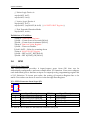
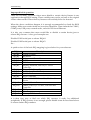
// Select Logic Device A
outp(0x002E, 0x07);
outp(0x002F, 0x0A);
// Active Logic Device A
outp(0x002E, 0xE7);
outp(0x002F, (inp(0x002F) & 0xF0) | ( Sel WDTO RST Register ));
// Exit Extended Function Mode
outp(0x002E, 0xAA);
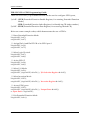
Definitions of Variables:
Value of Count-mode Register :
1) 0x00 -- Count down in seconds (Bit3=0)
2) 0x08 -- Count down in minutes (Bit3=1)
Value of Time-out Value Register :
1) 0x00 -- Time-out Disable
2) 0x01~0xFF -- Value for counting down
Value of Sel WDTO RST Register
1) 0x00 -- RST by LPC_RST (Bit3=0)
2) 0x08 -- RST by PWR_OK (Bit3=1)
3.6
GPIO
GPIO From Super I/O
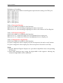
The PEB-2131VG2A provides 4 input/output ports from SIO that can be
individually configured to perform a simple basic I/O function. Users can configure
each individual port to become an input or output port by programming register bit
of I/O Selection. To invert port value, the setting of Inversion Register has to be
made. Port values can be set to read or write through Data Register.
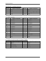
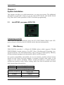
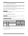
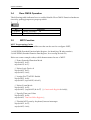
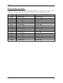
J13 : GPIO Connector from Super I/O
JP10
1
3
5
7
9
2
4
6
8
10
Header5Px2/2.54mm
PIN No.
Signal Description
PIN No.
Signal Description
1
GPIO Port50/OUT1(GP23)
2
GPIO Port54
3
GPIO Port51/OUT2(GP24)
4
GPIO Port55
5
GPIO Port52/IN-SENSE(GP22)
6
GPIO Port56
7
GPIO Port53
8
GPIO Port57
9
GND
10
5V
PS: Pin1 & 3 & 5 is that of Cash Drawer controls GPIO port
PEB-2131VG2A User’s Manual
3-5