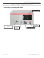
1
USER MANUAL
ATEQ PRIMUS F
SERIES
F620 / F610 / F670
Version 1.04
(No contractual photos)
Reference: RF-28300C-U
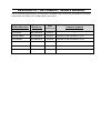
REVISION OF THE PRIMUS F SERIES MANUAL
Due to continuing improvements, the information contained in this user manual, the features and design
of this device are subject to be changed without prior notice.
Reference
Date
(week/year)
Chapters updated
First edition
RF-28300A-U
16/2013
-----
Second edition
RF-28300B-U
23/2013
Evolution of the firmware to v1.01.
Third edition
RF-28300C-U
22/2014
Evolution of the firmware to v1.04.
Edition/Revision
Index
Preamble / Presentation:
Definition, characteristics and
measurements principles (#673)
Front face and interfaces (#676)
Installation / Accessories:
Pneumatic supply (#677)
Starting up (#678)
Fitted Accessories (#682)
Optional Accessories (#683)
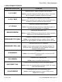
Error messages (#684)
Display Results in CC/min (#687)
F610 Electrics connectors (#692/1)
F620 Electrics connectors (#692/2)
F670 Electrics connectors (#692/7)
Pneumatics connectors (#693)
Parameters / Special Cycles:
Special Cycle (#623)
Service Special cycles (#631)
Programs selection (#679)
Programs parameters (leak) (#680)
Test cycle management (#681)
Burst test (#698)
Program Functions:
Functions management (#601)
Name (#602)
Program Sequence (#603)
Units (#604)
Automatic connector (option) (#605)
Check test (#606)
ATR (#607)
Prefill mode and fill mode (#608)
Valves codes & Aux outputs 24V (#609)
End of cycle (#610)
Mini valve (#611)
Rework limit (#612)
Sealed components (#613)
N test (#614)
Reference volume (#615)
Stamping (#617)
Temperature correction 1 (#618)
Peak hold (#620)
Sign (#621)
Filtering (#622)
Flow level (#624)
No negative (#625)
Absolute (#626)
Display mode function (#627)
No dump (#630)
Buzzer (#639)
External dump (#655)
ATF (#685)
Cut off (#686)
By pass (option) (#691)
Configuration Menu:
Date / Time (#635)
Language (#642)
Electronic Regulator (#645)
Regulator Control (#646)
Permanent Regulator (#647)
Piezo Auto Zero (#648)
Auto Zero short (#649)
Dump Level (#651)
RS232 (Automatism) (#652)
Security (#653)
I/O Configuration (#654)
IN7 Test (#656)
Smart Key (#688)
Pressure unit (#695)
USB (Automatism) (#696)
Results Menu / USB Menu:
Storage (#638)
Valves Service (#658)
I/O Service (#661)
System Info (#665)
Reset parameters (#669)
Results menu (#689)
Service / USB (#690)
CAN Status (#697)
Index
# 601: Functions management
# 602: Name
# 603: Program Sequence
# 604: Units
# 605: Automatic connector (option)
# 606: Check test
# 607: ATR
# 608: Prefill mode and fill mode
# 609: Valves codes & Aux outputs 24V
# 610: End of cycle
# 611: Mini valve
# 612: Rework limit
# 613: Sealed components
# 614: N test
# 615: Reference volume
# 617: Stamping
# 618: Temperature correction 1
# 620: Peak hold
# 621: Sign
# 622: Filtering
# 623: Special Cycle
# 624: Flow level
# 625: No negative
# 626: Absolute
# 627: Display mode function
# 631: Service Special cycles
# 635: Date / Time
# 638: Storage
# 639 : Buzzer
# 642: Language
# 645: Electronic Regulator
# 646: Regulator Control
# 647: Permanent Regulator
# 648 Piezo Auto Zero
# 649: Auto Zero short
# 651: Dump Level
# 652: RS232 (Automatism)
# 653: Security
# 654: I/O Configuration
# 655 : External dump
# 656: IN7 Test
# 658: Valves Service
# 661: I/O Service
# 665: System Info
# 669: Reset parameters
# 673: Definition, characteristics and
Measurements principles
# 676: Front face and interfaces
# 677: Pneumatic supply
# 678: Starting up
# 679: Programs selection
# 680: Programs parameters (Leak)
# 681: Test cycle management
# 682: Fitted Accessories
# 683: Optional Accessories
# 684: Error messages
# 685: ATF
# 686: Cut off
# 687: Display Results in CC/min
# 688: Smart Key
# 689: Results menu
# 690: Service / USB
# 691: By pass (option)
# 692/1: F610 Electrics connectors
# 692/2: F620 Electrics connectors
# 692/7: F670 Electrics connectors
# 693: Pneumatics connectors
# 695: Pressure unit
# 696: USB (Automatism)
# 697: CAN Status
# 698 : Burst Test
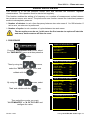
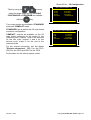
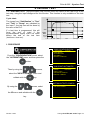
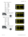
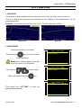
Sheet #601u – Functions management
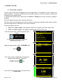
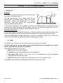
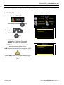
FUNCTIONS MANAGEMENT
The extended menu functions allow personalization and add options to the test cycle.
For ease of reading, these functions are hidden by default. To display the functions, follow the
process below.
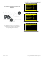
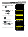
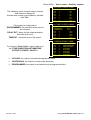
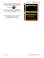
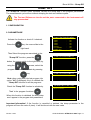
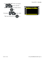
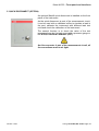
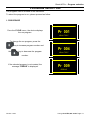
Process to display a function:
From the cycle menu, display the main menu
by pressing the
or
keys.
Then select the menu
2#4#/'6'45
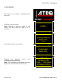
Select a program by using the
keys.
Ź Copy-Paste
Pr:01
LEAK TEST
Pr:02
LEAK TEST
Pr:03
LEAK TEST
Pr:04
----------------Pr:05
----------------Pr:06
----------------Pr:07
-----------------
2#4#/2T
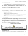
Then down to the end of the parameters
and select the FUNCTIONS menu.
Press. UNITE
Max. FILL
:
Min. FILL
:
Set FILL
:
Leak UNIT: Pa
Test FAIL
:
Ref. FAIL
:
Ź FUNCTIONS
: mbar
750.0
450.0
600.0
50
0
2#4#/ 2T(70%6+10
Ź More functions…
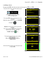
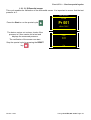
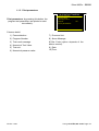
The functions menu is displayed, the validated
functions. Enter in the "More functions…"
menu.
Version 1.04a
User guide ATEQ 6th series Page 1/26
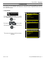
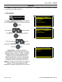
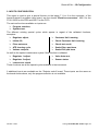
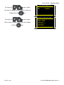
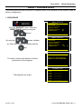
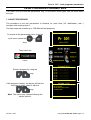
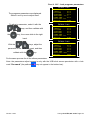
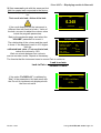
Sheet #601u – Functions management
2#4#/2T(70%6':
Ź NAME
PR:SEQUENCE
UNITS
FILTER
AUTO CONNECT
CHECK TEST
ATR0
ATR1
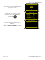
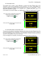
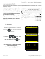
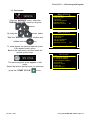
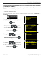
The available functions for the device are
displayed.
To validate a function, select it, press
,
the cursor slide to the right hand, with the
keys, select "Yes", then
validate with the
key, the cursor back
:
:
:
:
:
:
:
:
No
No
No
No
No
No
No
No
2#4#/2T(70%6':
Ź NAME
PR:SEQUENCE
UNITS
FILTER
AUTO CONNECT
CHECK TEST
ATR0
ATR1
:
:
:
:
:
:
:
:
Yes
No
No
No
No
No
No
No
to the left hand.
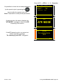
2#4#/ 2T(70%6+10
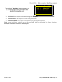
The validated function is now displayed, it
remains to be configured. (See sheets
corresponding to the functions).
Version 1.04a
Ź NAME: - - - - - - - - - More functions…
User guide ATEQ 6th series Page 2/26
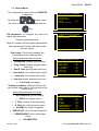
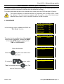
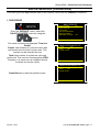
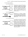
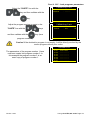
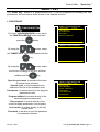
Sheet #601u – Functions management
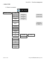
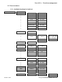
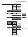
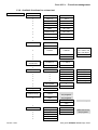
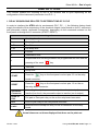
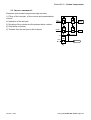
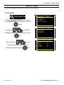
1. MENUS TREE
1.1. SPECIAL CYCLES MENU
SPECIAL CYCLES
>
None
Service Cycle =
Check Pressurre 1* /
Check P1 Reg 1**
* 1regulator option
Yes
Service Cycle =
Check P1 Reg 2**
** 2 regulators option
Yes
Leak Sensor
Check
Service Cycle =
Yes
Auto Test
*** X = 1 or 2
following the
regulators number
option.
Regulator X
adjust***
Infinite Fill
Piezo Auto Zero
Custom Unit Learn
Custom Unit
Check
Chck+Lrn Cust.
Unit
ATR Learning
Cycle
v
>
ATR TIME
>
0.0 S
Confirm
Sd Prt Pass Learn
Sd Prt Fail Learn
ATR + Custom
Learn
Check Test Result
Volume Comp.
Automatique
volume
Version 1.04a
User guide ATEQ 6th series Page 3/26
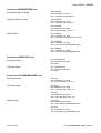
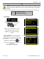
Sheet #601u – Functions management
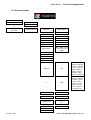
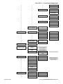
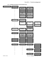
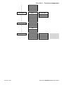
1.2. PARAMETERS MENU
PARAMETERS
Copy-Paste
V
V
Programs
01 to 128
>
Copy
Paste
V
>
Type: Leak test
>
Leak test
v
Auto Param
Coupl. A
Fill time
Stabilization time
Test time
Dump time
Press. UNIT
>
Delete Name
Reset program
>
>
>
>
>
0 > 650 s
0 > 650 s
0 > 650 s
0 > 650 s
0 >à 650 s
Bar > MPa > Kpa
> > Pa > Pts > Psi >
Mbar
Max PreFILL
Max FILL
Min FILL
Set PreFILL
Set FILL
LeakUnit
>
V
USA
Pa display
V
Rejet Calc
V
>
No / Yes
>
Pa > Pa/s
Volume Unit
>
L > ml > mm3 >
cm3
>
0,001 > 9999
V
Volume
Test reject
Reference reject
Version 1.04a
SI
Pa > Pa/s >
Pa(Hr) > Pa(Hr)/s
> cm3/s > cm3/mn
> cm3/h > mm3/s >
>
ml/s > ml/min >
ml/h > mmce >
mmce/s > pts >
Cal-Pa > Cal-Pa/s
Pa > Pa/s >
Pa(Hr) > Pa(Hr)/s
> cc/min > cc/s >
cc/h > in3/s >
>
in3/min > in3/h >
ft3/s > ft3/min >
ft3/h > mmce >
mmce/s > Pts
User guide ATEQ 6th series Page 4/26
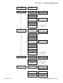
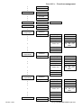
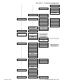
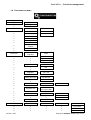
Sheet #601u – Functions management
Functions
V
Type Blockage
V
V
V
V
>
See Functions
menu
>
Blockage
Pressure Unit
V
V
V
Maximum fill
Minimum fill
Fill instruction
V
Functions
V
>
Desensitized
>
>
>
Delete Name
Reset program
Bar > Mpa > kpa >
Pa > Psi > mbar
Pressure Unit
Maximum fill
Minimum fill
Fill instruction
Reject Unit
Test Reject
Reference Reject
V
>
Functions
V
Type : Operator
>
Operator
v
Coupl. A
Test time
See Functions
menu
>
>
Burst test
Delete Name
Reset program
See Functions
menu
Functions
Version 1.04a
Bar > Mpa > kpa >
Pa > Psi > mbar
See Functions
menu
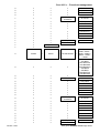
v
Coupl. A
Fill time
Stabilization time
Test time
Dump time
V
V
V
V
V
V
Type : burst test
Delete Name
Reset program
Coupl. A
Fill time
Dump time
V
V
Type :
Desensitized
V
V
V
V
V
V
>
>
Delete Name
Reset program
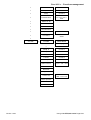
v
v
v
v
v
Coupl. A
>
0 to 650 s
v
Coupl. B
>
0 to 650 s
v
Ramp
>
0 to 650 s
User guide ATEQ 6th series Page 5/26
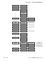
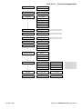
Sheet #601u – Functions management
v
Start measure
>
0 to 650 s
v
Step time
>
0 to 650 s
v
Dump
>
0 to 650 s
v
Pressure Unit
>
Bar > MPa > kPa >
Pa > Pts > PSI >
mbar
v
Maximum fill
v
Minimum fill
v
Start fill
v
Fill instruction
v
Step number
>
1 to 256
v
Functions
>
See Functions
menu
VOLUME
>
Delete Name
v
VOLUME
>
Reset program
v
v
Coupl. A
>
0 to 650 s
Coupl. B
>
0 to 650 s
Fill volume
>
0 to 650 s
Transfer
>
0 to 650 s
Dump
>
0 to 650 s
UNITE Pression
Bar > MPa > kPa >
> Pa pts > PSI > mbar
REMP Max
REMP Min
Consigne REMP
Volume unit
>
SI : cm3 / ml / l
SAE : cu in / cu ft
Volume pressure
Volume Max.
Volume Min.
Version 1.04a
User guide ATEQ 6th series Page 6/26
Sheet #601u – Functions management
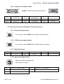
1.3. FUNCTIONS MENUS
1.3.1. Available functions for leak test
FUNCTIONS
Name
Pr: Sequence
v
v
v
Next Prog.
Inter-Cyc
All Results
Pass
>
>
>
>
XX+
0,0 S
No / Yes
No / Yes
v
T Fail
>
No / Yes
v
R Fail
>
No / Yes
v
Alarm
>
No / Yes
v
Pressure Out
>
No / Yes
v
Reworkable
>
No / Yes
v
Test Check
>
No / Yes
v
Units
>
SI
v
USA
v
Custom
Leakunit
v
v
Drift Unit
Name
Filtering
>
0 > 650 s
v
Automatic
Connectors
v
>
Coupling A
>
0 > 650 s
Coupling B
>
0 > 650 s
Test Check
Measure
>
0.0
v
Max Value
>
0.0
v
% Drift
>
20
v
Check time
>
0.3 s
Cal-Pa > Cal-Pa/S
> > Pa > Pa/S > Pa
(Hr) > Pa (Hr)/S
>
0 > 100 %
v
ATR0
Version 1.04a
>
Start
-Fs To +Fs
v
Transient
-Fs To +Fs
v
% Drift
0 > 100
v
v
ATR1
ATR2
ATR3
v
v
Prefill
v
Drift
0 > 200
>
Start
Transient
% Drift
Drift
Type P.Remp
v
>
>
>
-Fs To +Fs
-Fs To +Fs
0 > 100
0 > 200
Standard
v
Max Prefill
Set Prefill
User guide ATEQ 6th series Page 7/26
Sheet #601u – Functions management
v
v
v
v
v
v
v
v
v
v
v
v
v
v
v
v
v
v
Fill Mode
v
v
v
v
v
v
v
Dump Off
v
External dump
v
v
v
v
v
v
v
v
v
v
v
v
v
v
v
Pre fill regulator
Fill Mode
v
v
v
v
v
Fill regulator
>
No / Yes
>
Closed
v
Open
Mode
v
Valve Codes
v
v
v
v
v
v
v
v
v
v
24V outputs
v
v
v
Version 1.04a
v
v
v
Instruction
v
v
v
Ballistic
v
v
v
Fill Ramp
>
>
Aux 1
Delay Aux
Time Aux1
Aux 2
Yes
0.0 S
0.0 S
>
>
>
Set Prefill
Pre-Fill
Pre Dump
Max Prefill
Set Prefill
Pre-Fill
Pre Dump
Set Fill
Set Fill
Set Fill
Set Fill
Set Fill
Time Adj.
1
2
One choice for all
the programs
One choice for all
the programs
>
Continuous
Time
Ext. 1
Delay Ext
Time Ext1
Ext. 2
Ext. 3
Ext. 4
Ext. 5
Ext. 6
Int. 1
Int. 2
Set Prefill
Pre-Fill
Pre Dump
1
2
Standard
Instruction
Ballistic
Fill Ramp
Fill Adjust
>
Pre-Fill
Pre Dump
Closed only
Same time for all
the programs
No / Yes
0 > 650 s
0 > 650 s
User guide ATEQ 6th series Page 8/26
Sheet #601u – Functions management
v
v
v
End Of Cycle
v
v
v
v
Mini-Valve
v
Rework Limit
v
v
Sealed
components
v
v
v
v
Version 1.04a
Aux 3
Aux 4
>
Auto Reset
Dump + Reset
Fill Time
Double Reset
>
Diff A-Z
>
Test Rework
Ref. Rework
>
Standard
Large Leak
>
0 > 650 s
>
Coupling A
Fill Volume
Transfer
Dump Time
v
Press. Unit
v
v
v
Sealed
components 3
v
v
Max Fill
Min Fill
Set Fill
>
v
v
Coupling A
Fill Volume
Dump volume
Transfer
Dump Time
v
Press. Unit
v
v
v
Sealed
components 2
v
v
v
v
Max Fill
Min Fill
Set Fill
>
>
>
>
>
>
0 > 650 s
0 > 650 s
0 > 650 s
0 > 650 s
0 > 650 s
Bar > Mpa > Kpa
> > Pa > Pts > Psi >
Mbar
Standard
Large Leak
>
Coupling A
Fill Volume
Transfer
Dump Time
v
Press. Unit
v
v
v
N Tests
v
Max Fill
Min Fill
Set Fill
0 > 100 %
0 > Tolerance A
>
0 > 650 s
0 > 650 s
0 > 650 s
0 > 650 s
Bar > Mpa > Kpa
> > Pa > Pts > Psi >
Mbar
Standard
Large Leak
>
>
>
>
>
Tolerance A
Tolerance B
>
>
>
>
>
>
0 > 650 s
0 > 650 s
0 > 650 s
0 > 650 s
Bar > Mpa > Kpa
> > Pa > Pts > Psi >
Mbar
User guide ATEQ 6th series Page 9/26
Sheet #601u – Functions management
Peak Hold
v
Ref. Volume
v
Stamping
v
v
v
v
v
v
v
Temp. Corr. 1
v
v
v
Sign
v
Flow Level
v
No Negative
v
Absolute
v
Synchro test
v
Bypass
v
v
v
Display Mode
v
v
v
v
Buzzer
v
v
v
v
Cut Off
v
ATF
Version 1.04a
>
No / Yes
> Volume Référence
Duration
All Results
Pass
T Fail
R Fail
Alarm
Pressure Out
Correction
Test Time
Offset
0 > 200 %
0,1 > 650 S
0 > FS
>
No / Yes
>
Pa or cm3/min
>
No / Yes
>
Pa or cm3/min
>
No / Yes
>
Pa or cm3/min
No / Yes
>
No / Yes
>
Fill
Pfill
Pfill + Fill
>
XXXX
XXX.X
XX.XX
X.XXX
>
Pass part
Fail part
Alarm
End of cycle
>
>
>
>
No / Yes
No / Yes
No / Yes
No / Yes
>
% Cut Off
>
0 > 100%
>
ATF time
>
0,1 > 650 S
Ex IN7 test
10 beeps
Long beep
Long beep
10 beeps
User guide ATEQ 6th series Page 10/26
Sheet #601u – Functions management
1.3.2. Available functions for blockage test
FUNCTIONS
Name
Pr: Sequence
v
v
v
Next Prog.
Inter-Cyc
All Results
Pass
>
>
>
>
XX+
0,0 S
No / Yes
No / Yes
v
Fail
>
No / Yes
v
Alarm
>
No / Yes
v
Pressure Out
>
No / Yes
Coupling A
>
0 > 650 s
Coupling B
>
0 > 650 s
v
Automatic
Connectors
v
v
Prefill
v
v
v
v
v
v
Fill Mode
v
v
v
v
Permanent dump
v
Dump Off
v
External dump
v
>
Type P.Remp
v
v
v
Pre fill regulator
Fill Mode
v
Fill regulator
>
No / Yes
>
No / Yes
>
Closed
Open
Mode
Version 1.04a
>
>
Standard
v
v
v
1
2
Set Prefill
Pre-Fill
Pre Dump
Standard
Set Fill
1
2
One choice for all
the programs
One choice for all
the programs
>
Continuous
Time
v
Valve Codes
Ext. 1
No / Yes
v
Delay Ext
0.0 S
v
v
v
v
v
v
v
v
Time Ext1
Ext. 2
Ext. 3
Ext. 4
Ext. 5
Ext. 6
Int. 1
Int. 2
0.0 S
Closed only
Same time for all
the programs
User guide ATEQ 6th series Page 11/26
Sheet #601u – Functions management
24v Outputs
v
v
v
v
v
v
End Of Cycle
v
v
v
v
Mini-Valve
v
Stamping
v
v
v
v
v
v
Buzzer
Version 1.04a
>
Aux 1
Delay Aux
Time Aux1
Aux 2
Aux 3
Aux 4
>
>
>
No / Yes
0 > 650 s
0 > 650 s
>
0 > 650 s
>
>
>
>
No / Yes
No / Yes
No / Yes
No / Yes
Auto Reset
Dump + Reset
Fill Time
Double Reset
Diff A-Z
Duration
All Results
Pass
Fail
Alarm
Pressure Out
>
Pass part
Fail part
Alarm
End of cycle
User guide ATEQ 6th series Page 12/26
Sheet #601u – Functions management
1.3.3. Available functions for Desensitized test
FUNCTIONS
Name
Pr: Sequence
v
v
v
Next Prog.
Inter-Cyc
All Results
Pass
>
>
>
>
XX+
0,0 S
No / Yes
No / Yes
v
Fail
>
No / Yes
v
Alarm
>
No / Yes
v
Pressure Out
>
No / Yes
v
Reworkable
>
No / Yes
v
Test Check
>
No / Yes
v
Units
>
SI
v
USA
v
Custom
Leakunit
Cal-Pa > Cal-Pa/S
> > Pa > Pa/S > Pa
(Hr) > Pa (Hr)/S
v
Drift Unit
>
v
Name
Automatic
Connectors
v
>
Coupling A
>
0 > 650 s
Coupling B
>
0 > 650 s
0 > 100 %
v
ATR0
Version 1.04a
>
Start
-Fs To +Fs
v
Transient
-Fs To +Fs
v
% Drift
0 > 100
v
v
ATR1
ATR2
ATR3
v
v
Prefill
v
v
v
v
v
v
v
v
v
v
Drift
0 > 200
>
Start
Transient
% Drift
Drift
Type P.Remp
v
v
v
v
v
v
v
v
v
v
>
>
>
-Fs To +Fs
-Fs To +Fs
0 > 100
0 > 200
Standard
v
v
v
v
Instruction
v
v
v
Ballistic
v
Max Prefill
Set Prefill
Pre-Fill
Pre Dump
Set Prefill
Pre-Fill
Pre Dump
Set Prefill
Pre-Fill
User guide ATEQ 6th series Page 13/26
Sheet #601u – Functions management
v
v
v
v
v
v
v
v
v
Fill Mode
v
v
v
v
v
v
v
Dump Off
v
External dump
v
v
v
v
v
v
Pre fill regulator
Fill Mode
v
v
v
v
v
Fill regulator
>
No / Yes
>
Closed
v
Open
Mode
v
Valve Codes
v
v
v
v
v
v
v
v
v
v
24V outputs
v
v
v
v
v
v
End Of Cycle
v
v
v
v
Mini-Valve
Version 1.04a
v
v
Fill Ramp
>
>
Aux 1
Delay Aux
Time Aux1
Aux 2
Aux 3
Aux 4
>
Auto Reset
Dump + Reset
Fill Time
Double Reset
>
Diff A-Z
Set Fill
Set Fill
Set Fill
Set Fill
Set Fill
Time Adj.
1
2
One choice for all
the programs
One choice for all
the programs
>
Continuous
Time
Ext. 1
Delay Ext
Time Ext1
Ext. 2
Ext. 3
Ext. 4
Ext. 5
Ext. 6
Int. 1
Int. 2
Max Prefill
Set Prefill
Pre-Fill
Pre Dump
1
2
Standard
Instruction
Ballistic
Fill Ramp
Fill Adjust
>
Pre Dump
Yes
0.0 S
0.0 S
>
>
>
No / Yes
0 > 650 s
0 > 650 s
>
0 > 650 s
Closed only
Same time for all
the programs
User guide ATEQ 6th series Page 14/26
Sheet #601u – Functions management
Rework Limit
v
v
Peak Hold
v
Stamping
v
v
v
v
v
v
Sign
v
Flow Level
v
No Negative
v
Absolute
v
Bypass
v
v
v
Display Mode
v
v
v
v
Buzzer
v
v
v
v
Cut Off
v
ATF
Version 1.04a
>
Test Rework
Ref. Rework
>
No / Yes
Duration
All Results
Pass
T Fail
Alarm
Pressure Out
>
No / Yes
>
Pa or cm3/min
>
No / Yes
>
Pa or cm3/min
>
No / Yes
>
Pa or cm3/min
No / Yes
>
Fill
Pfill
Pfill + Fill
>
XXXX
XXX.X
XX.XX
X.XXX
>
Pass part
Fail part
Alarm
End of cycle
>
>
>
>
No / Yes
No / Yes
No / Yes
No / Yes
>
% Cut Off
>
0 > 100%
>
ATF time
>
0,1 > 650 S
10 beeps
Long beep
Long beep
10 beeps
User guide ATEQ 6th series Page 15/26
Sheet #601u – Functions management
1.3.4. Available functions for operator test
FUNCTIONS
Name
Pr: Sequence
v
v
v
Next Prog.
Inter-Cyc
All Results
Pass
>
>
>
>
XX+
0,0 S
No / Yes
No / Yes
v
Fail
>
No / Yes
Coupling A
>
0 > 650 s
Coupling B
>
0 > 650 s
v
Automatic
Connectors
v
v
Valve Codes
v
v
v
v
v
v
v
v
v
v
24V outputs
v
v
v
v
v
v
Stamping
v
v
v
v
v
v
Buzzer
v
v
v
Version 1.04a
>
Ext. 1
Delay Ext
Time Ext1
Ext. 2
Ext. 3
Ext. 4
Ext. 5
Ext. 6
Int. 1
Int. 2
>
Aux 1
Delay Aux
Time Aux1
Aux 2
Aux 3
Aux 4
Yes
0.0 S
0.0 S
>
>
>
No / Yes
0 > 650 s
0 > 650 s
>
>
>
>
No / Yes
No / Yes
No / Yes
No / Yes
Same time for all
the programs
Duration
All Results
Pass
Fail
Alarm
Pressure Out
>
Pass part
Fail part
Alarm
End of cycle
10 beeps
Long beep
Long beep
10 beeps
User guide ATEQ 6th series Page 16/26
Sheet #601u – Functions management
1.3.5. Available functions for Burst test
FUNCTIONS
Name
Burst = OK
Pr: Sequence
v
v
v
>
>
No / Yes
Next Prog.
Inter-Cyc
All Results
Pass
>
>
>
>
XX+
0,0 S
No / Yes
No / Yes
v
T Fail
>
No / Yes
v
R Fail
>
No / Yes
v
Alarm
>
No / Yes
v
Pressure Out
>
No / Yes
v
Reworkable
>
No / Yes
v
Test Check
>
No / Yes
Coupling A
>
0 > 650 s
Coupling B
v
Fill regulator
>
0 > 650 s
>
1
2
v
Automatic
Connectors
v
v
Fill Mode
v
v
External dump
>
>
v
Closed
Open
Mode
v
Valve Codes
v
v
v
v
v
v
v
v
v
v
24V outputs
v
v
v
v
v
v
End Of Cycle
Version 1.04a
One choice for all
the programs
One choice for all
the programs
>
Continuous
Time
Ext. 1
Delay Ext
Time Ext1
Ext. 2
Ext. 3
Ext. 4
Ext. 5
Ext. 6
Int. 1
Int. 2
>
Aux 1
Delay Aux
Time Aux1
Aux 2
Aux 3
Aux 4
>
Auto Reset
Yes
0.0 S
0.0 S
>
>
>
Closed only
Same time for all
the programs
No / Yes
0 > 650 s
0 > 650 s
User guide ATEQ 6th series Page 17/26
Sheet #601u – Functions management
v
v
v
v
Mini-Valve
v
Stamping
v
v
v
v
v
v
v
Buzzer
Version 1.04a
Dump + Reset
Fill Time
Double Reset
>
Diff A-Z
>
0 > 650 s
>
>
>
>
No / Yes
No / Yes
No / Yes
No / Yes
Duration
All Results
Pass
T Fail
R Fail
Alarm
Pressure Out
>
Pass part
Fail part
Alarm
End of cycle
10 beeps
Long beep
Long beep
10 beeps
User guide ATEQ 6th series Page 18/26
Sheet #601u – Functions management
1.3.6. Available functions for volume test
FUNCTIONS
Name
Pr: Sequence
v
v
v
Next Prog.
Inter-Cyc
All Results
Pass
>
>
>
>
XX+
0,0 S
No / Yes
No / Yes
v
Fail
>
No / Yes
v
Alarm
>
No / Yes
v
Pressure Out
>
No / Yes
v
Reworkable
>
No / Yes
v
Test Check
>
No / Yes
v
Units
>
SI
v
USA
v
Custom
v
v
v
Automatic
Connectors
v
v
Fill Mode
v
v
v
v
v
v
v
Dump Off
v
External dump
v
Drift Unit
Name
>
Coupling A
>
0 > 650 s
Coupling B
>
0 > 650 s
Fill Mode
v
v
v
v
v
Fill regulator
>
No / Yes
>
Closed
Open
Mode
v
Valve Codes
v
v
v
v
v
Version 1.04a
Leakunit
Ext. 1
Delay Ext
Time Ext1
Ext. 2
Ext. 3
Ext. 4
Standard
Instruction
Ballistic
Fill Ramp
Fill Adjust
>
Cal-Pa > Cal-Pa/S
> > Pa > Pa/S > Pa
(Hr) > Pa (Hr)/S
>
0 > 100 %
Set Fill
Set Fill
Set Fill
Set Fill
Set Fill
Time Adj.
1
2
One choice for all
the programs
One choice for all
the programs
>
Continuous
Time
Yes
0.0 S
0.0 S
Closed only
Same time for all
the programs
User guide ATEQ 6th series Page 19/26
Sheet #601u – Functions management
v
v
v
v
v
24V outputs
v
v
v
v
v
v
Stamping
v
v
v
v
v
v
Buzzer
Version 1.04a
Ext. 5
Ext. 6
Int. 1
Int. 2
>
Aux 1
Delay Aux
Time Aux1
Aux 2
Aux 3
Aux 4
>
>
>
No / Yes
0 > 650 s
0 > 650 s
>
>
>
>
No / Yes
No / Yes
No / Yes
No / Yes
Duration
All Results
Pass
Fail
Alarm
Pressure Out
>
Pass part
Fail part
Alarm
End of cycle
10 beeps
Long beep
Long beep
10 beeps
User guide ATEQ 6th series Page 20/26
Sheet #601u – Functions management
1.4. CONFIGURATION MENU
Configuration
Language
V
v
Automatic Volume
French
English
>
Fill
>
0 > 650 s
v
Transfer
>
0 > 650 s
v
Dump
>
0 > 650 s
v
v
v
v
Volume Unit
Ref Volume
Pressur Volume
Internal Ref Vol
Internal Test
Volume
No Volume
>
None
v
v
v
v
v
v
v
v
v
Electronic
Regulator
v
v
v
v
Regulator Contrl
v
v
Permanent
Regulator
v
Piezzo Auto-zero
v
v
Short Auto-zero
v
v
Pressure Unit
v
v
v
v
v
v
Automatism
V
V
V
v
Blow
v
v
Dump Level
Pneumatic
>
v
v
v
v
v
v
v
v
Version 1.04a
>
USB
v
v
v
Regulator 1 P.E.
Regulator 2 P.E.
All
>
Auto
Ext.
>
No / Yes
>
Nb Minutes
Nb Cycles
>
No / Yes
>
Bar / Mb / Psi / Pts
/ Pa / Kpa / Mpa
>
>
0 > 650 s
Regulator 1 oo 2
v
v
Pressure
>
Max Blow
Min Blow
Blow Instruction
Printer
v
v
v
>
Print frame
v
v
v
>
Pressure
Prog name
Date & Time
Lines before
User guide ATEQ 6th series Page 21/26
Sheet #601u – Functions management
V
V
V
V
v
v
v
v
v
v
v
v
v
v
v
v
v
v
v
v
v
v
v
v
v
v
v
v
v
v
v
v
v
v
v
v
v
v
v
v
v
v
v
v
v
v
v
v
v
Supervision
V
RS232
V
v
v
v
V
V
V
V
V
V
V
V
V
v
v
v
v
v
v
v
v
v
v
v
v
v
v
v
v
v
v
V
v
v
V
V
V
V
V
V
V
V
V
V
v
v
v
v
v
v
v
v
v
v
v
v
v
v
v
v
v
v
v
v
v
Frame
v
v
v
v
v
v
v
Sending
Conditions
v
v
v
v
v
v
v
v
Export
Print Parameters
Version 1.04a
>
Printer
v
v
v
v
Sending
Conditions
v
v
v
v
v
v
v
v
Export
Print Parameters
>
RS Parameters
Lines after
Inter line
Form feed
All results
Pass part
Test fail
Reference fail
Alarm
Pressure out
Reworkable
Test check
>
>
>
No / Yes
Speed
4800 – 9600 –
19200 – 28800 –
38400 – 57600 115200
1st/7 Bits/0
1st/7 Bits/1
1st/7 Bits/Even
1st/7 Bits/Odd
1st/8 Bits/None
1st/8 Bits/0
1st/8 Bits/1
1st/8 Bits/Even
1st/8 Bits/Odd
Pressure
Prog name
Date & Time
Lines before
Lines after
Inter line
Form feed
All results
Pass part
Test fail
Reference fail
Alarm
Pressure out
Reworkable
Test check
>
No / Yes
User guide ATEQ 6th series Page 22/26
Sheet #601u – Functions management
V
V
V
V
V
V
V
V
V
V
v
v
v
Date & Time
v
v
v
v
v
v
v
Fieldbus
v
v
v
v
V
V
V
V
v
v
v
v
Outputs Config
v
v
v
V
v
V
V
V
V
V
V
V
v
v
v
v
v
v
v
V
v
Supervision
>
Year
Month
Day
Hour
Minutes
Seconds
>
Adress /Mode…*
* Different
following installed
fieldbus
IP Adress
Sub Mask
Gateway
IP
SM
GW
>
I/O
>
Aux 1
Aux 2
Aux 3
Aux 4
Output
>
Standard /
Compact
Ext. 1
Ext. 2
Ext. 3
Ext. 4
Ext. 5
Ext. 6
>
>
>
>
>
>
Programmed /
Continuous /
Cycling
v
Int. 1
>
V
v
Int. 2
>
V
V
v
Config entrées
In 7 Test
>
V
v
In 7
>
V
v
In 8
>
V
v
In 9
>
In 1
In 2
In 3
In 4
In 5
In 6
>
>
>
>
>
>
V
v
v
v
v
v
v
v
Security
V
V
Version 1.04a
Valves Codes
>
I/O
>
>
Programmed /
Continuous /
Cycling
No / Yes
Special Cycles
Available
Special Cycles
Available
Special Cycles
Available
v
Valves Codes
>
Start Off
v
Password
>
No / Yes
>
Unlock
>
Special Cycles
+ Sync Test
User guide ATEQ 6th series Page 23/26
Sheet #601u – Functions management
V
V
V
Miscellaneous
Lock
Erase
>
Smart Key
>
Special Cycle
Menu
Special Cycle
Special Cycles
Available
Parameters
Program Defined
Run Program
Last results
Version 1.04a
User guide ATEQ 6th series Page 24/26
Sheet #601u – Functions management
1.5. SERVICE MENU
Service
Reset parameters
v
CAN Status
V
V
V
V
v
I/O State
>
No / Yes
>
Sensor
I/O
Valves Code
I/O (2)
Valves Code (2)
>
Sensor
V
I/O
V
V
V
v
Valve counter
V
V
v
Device Info
v
v
v
v
v
Service Cycles
Valves Code
I/O (2)
Valves Code (2)
Version 1.04a
>
Partial
Total
Partial reset
>
S/N
Texts
Soft Info
Boot Info
Settings Info
>
>
Out 1 > 4 / DAC
In 1 > In 9 / Out 1
>
> Out 9
>
Out 1 > Out 8
Texts version
No / Yes
User guide ATEQ 6th series Page 25/26
Sheet #601u – Functions management
1.6. RESULTS MENU
Results
Save on
V
V
V
>
Last Results
>
V
V
Statistics
>
None
Internal
USB
Display of the 6
lasts results
Results reset
Program
Total
Pass
Test fail
Reference fail
Reworkable
Alarm
Print all statistics
reset all statistics
1.7. MENUS USB
USB
Save parameters
Restore parameters
Version 1.04a
User guide ATEQ 6th series Page 26/26
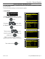
Sheet # 602u –Name function
NAME FUNCTION
This function allows identifying a program, for example the name of the tested part.
2#4#/ 2T(70%6+10
Activate the function or check if it checked.
Press the
Ź NAME :
More functions…
key, the cursor slide to the
right hand.
2#4#/ 2T(70%6+10
By using the
arrows, select
NAME :
More functions…
Ż
the desired characters, switch to the following
with the
key.
Repeat the operation until having the entire
name.
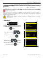
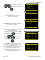
2#4#/ 2T(70%6+10
NAME : BOD#
More functions…
Ż
When the entire name is entered,
press
until the last character, the
cursor slide to the left hand.
Once the name enterred, press one
time
to make appears the ""
character, then press
2#4#/ 2T(70%6+10
NAME : BODY
More functions…
Ż
to back the
cursor on the left hand side.
2#4#/'6'45
Back to the parameters menu, the program
name appears.
Version 1.04a
Copy-Paste
Ź Pr:01
BODY
Pr:02
LEAK TEST
Pr:03
LEAK TEST
Pr:04
----------------Pr:05
----------------Pr:06
----------------Pr:07
-----------------
User guide ATEQ 6th series Page 1/2
Sheet # 602u –Name function
$1&;
100.0
mbar
During the test cycle the name is displayed
(on top of the screen).
050
Pa
TEST
005
Pr 01
Pa
1.4 s
2#4#/2T
To delete the name, enter the program
parameters menu, select "TYPE", then
validate with
.
Ź TYPE : LEAK TEST
COUPL A
:
0.0 s
FILL TIME :
0.0 s
STAB TIME :
0.0 s
TEST TIME : Inf. s
DUMP TIME :
0.0 s
Press. UNIT: bar
Max FILL
:
0.000
2T6'566;2'
The name and program deletion menu is
displayed.
Ź Delete name
Reset program
Note: if the program is deleted, the program
name is deleted too.
Version 1.04a
User guide ATEQ 6th series Page 2/2
Sheet #603u – Program sequencing function
PROGRAM SEQUENCING FUNCTION
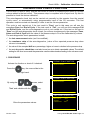
This function enables several tests to be carried out by the instrument one after the other. The
instrument offers 8 program sequencing criteria.
The sequencing order can be edited; the choice of the following program is defined in the
parameters. By default the programs are sequenced according to their original number P+1.
1. PROCEDURE
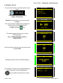
2#4#/ 2T(70%6+10
Activate the function or check if it checked.
Press the
Ź PR:SEQUENCE
More functions…
:
No
key, the cursor slide to the
right hand.
2#4#/ 2T(70%6+10
By using the
arrows, select
"Yes" and validate with the
PR:SEQUENCE
More functions…
:
Yes Ż
key. The
Program sequence menu is displayed.
Associated parameters to be set:
¾ NEXT PROGRAM: next program to be
chained.
¾ INTER-CYCLE: wait or coupling time
between the two cycles.
Chaining conditions:
¾ ALL RESULTS: always chains to the
next program.
¾ PASS: chains on a good part.
¾ TEST FAIL: chain on a bad test part.
¾ REFERENCE FAIL: chain on a bad
reference part.
¾ ALARM: chains if an alarm is triggered.
(70%6245'37'0%
Ź NEXT PROG
INTER-CYC:
ALL RESULTS
PASS
T FAIL
R FAIL
ALARM
PRESSURE OUT
: 02+
0.0 s
: No
: Yes
: No
: No
: No
: No
¾ PRESSURE OUT OF LIMIT: Chains if
the pressure is out of the pressure limits.
.
¾ REWORKABLE: chains if reworkable is
valid.
volume
¾ CALIBRATION:
check pass or fail.
Version 1.04a
calibration
User guide ATEQ 6th series Page 1/2
Sheet #603u – Program sequencing function
2#4#/'6'45
When an active program is sequenced with
another program, a "+" is displayed next to the
program number.
Version 1.04a
Copy-Paste
Ź Pr:01+ LEAK TEST
Pr:02
LEAK TEST
Pr:03
LEAK TEST
Pr:04
----------------Pr:05
----------------Pr:06
----------------Pr:07
-----------------
User guide ATEQ 6th series Page 2/2
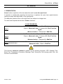
Sheet #604u – Units function
UNITS FUNCTION
This function allows the operator to choose the pressure and leak measurement units.
The different unit systems are: SI (International metric system, mm3/s, cm3/s, cm3/min, cm3/h,
ml/s, ml/min and ml/h) USA/SAE (Anglo-Saxon unit system, inch3/s, inch3/min, inch3/h, ft3/s,
ft3/min and ft3/h) and CUSTOM measurement units.
If a custom measurement unit is used, it is possible to name it. This name will appear instead of
the unit.
Activate the function or check if it checked.
2#4#/ 2T(70%6+10
Press the
key, the cursor slide to the
Ź UNITS
: SI
More functions…
right hand.
By using the
arrows, select
the units system.
SI:
SI Units System (Metric International System,
mm3/s, cm3/s, cm3/min, cm3/h, ml/s, ml/min
and ml/h).
2#4#/ 2T(70%6+10
Ź UNITS
: SI
More functions…
Ż
Select the leak unit.
Then validate by pressing
.
SAE:
2#4#/ 2T(70%6+10
SAE Units System (Anglo-Saxons Units,
inch3/s, inch3/min, inch3/h, ft3/s, ft3/min and
ft3/h).
Then validate by pressing
Ź UNITS
: SAE
More functions…
Ż
.
CUSTOM:
CUSTOM personalized measurement units.
The CUSTOM unit option allows calibrating
the device using a master leak. A learning
special cycle is necessary for this operation
(see the special cycle’s sheet). The activation
of this unit gives access to another special
cycle for checking.
Then validate by pressing
Version 1.04a
2#4#/ 2T(70%6+10
Ź UNITS
: CUSTOM
More functions…
Ż
.
User guide ATEQ 6th series Page 1/4
Sheet #604u – Units function
Select Cal-Pa or Cal-Pa/s.
"Drift Unit": tolerance limit for the calibration
drift. Checked using the "CAL Check" special
cycle. If this value is exceeded, an alarm is
triggered (default value: 20%).
4#/ 2T(70%670+6
Ź LeakUnit:
Cal-Pa
Drift Unit
: 020 %
NAME: TRIAL
"NAME": Naming of the unit.
Version 1.04a
User guide ATEQ 6th series Page 2/4
Sheet #604u – Units function
1. SPECIAL CYCLES
1.1. CUSTOM UNIT LEARNING
If the 4 units of flow are not appropriate for the application, it is possible to use a custom unit
mode (manual). To do this, a learning cycle must be carried out so that a custom unit value will
correspond to a pressure drop.
To access this special cycle, select the unit Cal-Pa or Cal-Pa/s as a FAIL unit when creating a
program.
Then the special learning cycle must be carried out.
The first custom unit learning cycle must be carried out using the specials cycles menu so that a
leak rate target which is different to zero can be entered.
On these outputs we have:
¾ "Pass" and "end of cycle" if the target is lower than or equal to the FAIL reject level,
¾ "Fail" and "end of cycle" if the target is greater than the test FAIL level.
From the main menu, enter the special cycle
menu.
In the special cycle menu, select the
"Custom unit learn" cycle.
52'%;%.'
none
Regul. adjust
Infinite fill
Piezo auto zero
Ź Custom unit learn
Custom unit check
Chck+Lrn Cust. Unit
/#+0 52'%;%.'
Adjust the parameters, select "CONFIRM" and
press
Ź Leak Rate
LeakUnit
CONFIRM
:
:
3.00
Cal-Pa
.
Unit Lrn
The cycle screen is displayed confirming the
special cycle selection. Press the
"START CYCLE"
Pr 001
key.
LEAK TEST
600.0
mbar
At the end of the special cycle, the result must
be pass (OK).
3.33
TRIAL
3.00
Pr 01
Version 1.04a
OK
TRIAL
READY
User guide ATEQ 6th series Page 3/4
Sheet #604u – Units function
1.2. CUSTOM UNIT CHECK
This special cycle is used to verify calibration in custom unit mode (Please refer to the
explanation in the previous paragraph for more information). The Custom "unit check" cycle
measures whether the calibration has drifted beyond the limits set as a percentage. If these
have been exceeded, an alarm will be triggered and a "custom unit learn" cycle or an
instrument check will be required.
If the opposite is the case the "Pass" and "end of cycle" or "Fail" and "end of cycle" Fail level.
Unit check
The cycle screen is displayed confirming the
special cycle selection. Press the
"START CYCLE"
Pr 001
key.
LEAK TEST
600.0
mbar
At the end of the special cycle, the result must
be pass (OK).
OK
3.33
TRIAL
3.00
Pr 01
TRIAL
READY
1.3. CUSTOM UNIT CHECK + CUSTOM UNIT LEARN
This special cycle enables the checking of learning in the custom unit mode (Please refer to the
previous paragraphs for more information). The checking cycle measures the drift in relation to
the imposed percentage limits. If the limits are not exceeded, a Custom Unit learn cycle will be
carried out automatically to refresh the value learnt.
If the percentage limit is exceeded, the instrument will display a Custom Unit drift error.
Chk+Lrn
The cycle screen is displayed confirming the
special cycle selection. Press the
"START CYCLE"
Pr 001
key.
LEAK TEST
600.0
mbar
At the end of the special cycle, the result must
be pass (OK).
3.33
TRIAL
3.00
Pr 01
Version 1.04a
OK
TRIAL
READY
User guide ATEQ 6th series Page 4/4
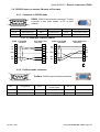
Sheet #605u – Automatic connectors function
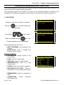
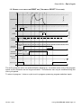
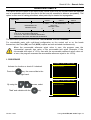
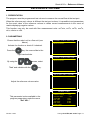
AUTOMATIC CONNECTORS FUNCTION
The automatic connector is a pneumatic control enabling the pilot of an external logic (valve,
pneumatic device…). This control is activated at the start of the cycle and is released at the end
of the cycle.
W
F
S
T
D
START
Time B
Automatic
Active
Connector A Inactive
Active
Automatic
Connector B Inactive
Time B
End of cycle
If several programs are sequenced, the automatic connectors are activated according to the
times set as parameters in the first program and are deactivated according to the times set as
parameters in the last program in the sequence.
Once an automatic connector has been activated, it will remain active for all cycles between the
first and last program in the sequence.
2#4#/ 2T(70%6+10
Activate the function or check if it checked.
Press the
Ź AUTO CONNECT :
More functions…
No
key, the cursor slide to the
right hand.
2#4#/ 2T(70%6+10
By using the
"Yes" and validate with the
arrows, select
AUTO CONNECT :
More functions…
Yes
Ż
key.
(70%6#761%100'%
Enter the values for the associated
parameters: "COUPLING A" and
"COUPLING B".
Version 1.04a
Ź COUPL. A
COUPL. B
:
:
0.0 s
0.0 s
User guide ATEQ 6th series Page 1/1
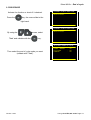
Sheet #606u – Calibration check function
CALIBRATION CHECK FUNCTION
This function is used to verify that the test circuit is correct by measuring the effect of a known
volume added to the test circuit. This pressure drop is compared with a reject level. By this it's
possible to check the device calibration.
This auto-diagnostic check test can be carried out manually by the operator from the special
cycle's menu, or automatically using programmable input of the I/O connector. The first
operation must be carried out manually in order to set the volume parameter.
This cycle is only carried out if the test result is "Pass" and in this case you will see the
messages Pass and End of Cycle. If the test result is "Fail", you will see the messages Fail
and End of Cycle, and the auto-diagnostics cycle is not carried out. If the test on the part is
"Pass" and the auto-diagnostics check is bad, you will see simultaneously the messages: Pass,
Alarm and End of Cycle with the value of the pressure drop in Pa of the calibration by volume.
The auto-diagnostics check parameters include:
9 the last measurement value (can't be modified),
9 the maximum value of the auto-diagnostics, (value of the expected pressure drop when
volume is increased),
9 the value of the accepted drift as a percentage, higher or lower in relation to the pressure drop.
9 the auto-diagnostics check time must also be set so as to obtain repeatable values. The default
setting for this time is zero and the parameter must be determined according to the volumes used.
1. PROCEDURE
2#4#/ 2T(70%6+10
Activate the function or check if it checked.
Press the
Ź CHECK TEST
More functions…
:
No
key, the cursor slide to the
right hand.
2#4#/ 2T(70%6+10
By using the
arrows, select
"Yes" and validate with the
CHECK TEST
More functions…
:
Yes
Ż
key.
T(70%6%*'%-6'5
Enter the parameters values.
Version 1.04a
Ź Measure :
Max value :
% Drift
CheckTime :
- 0.1
50.0
: 20
5.0 s
User guide ATEQ 6th series Page 1/3
Sheet #606u – Calibration check function
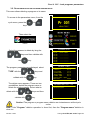
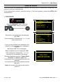
2. SPECIAL CYCLE
From the main menu, enter the special cycle
menu.
52'%;%.'
none
Regul. adjust
Infinite fill
Piezo auto zero
Ź Check Test Result
In the special cycle menu, select
"Check Test Result".
52'%;%.'
Remind: it's important to have a pass part
plugged.
CheckTest
Pr 001
The cycle screen is displayed confirming the
special cycle selection. Press the
"START CYCLE"
LEAK TEST
key.
The learning special cycle carry out the
following steps:
600.0
mbar
050
Pa
CHECK TEST
22
FILL / STABILIZATION / TEST et
CHECK TEST
Pr1
Pa
1.4 s
600.0
mbar
At the end of the special cycle, the result must
be pass (OK).
50
Pa
OK
22
Pr1
Pa
READY
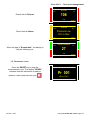
600.0
mbar
OK
0.300
cm3/mn
0.200 cm3/mn
20 Pa
Example with flow unit and Pascal display.
Pr1
READY
T(70%6%*'%-6'5
It's possible to check the recorded parameters
by the special cycle by pressing the
Ź Measure :
Max value :
% Drift
CheckTime :
90.0
100.0
: 20
5.0 s
.key just after the special cycle end.
Version 1.04a
User guide ATEQ 6th series Page 2/3
Sheet #606u – Calibration check function
ALARM
In case of wrong calibration, an alarm is
triggered.
TEST CHECK DEFAULT
CHECK = 2.5 Pa
Pr1
Version 1.04a
0.300
cm3/mn
READY
User guide ATEQ 6th series Page 3/3
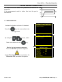
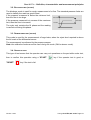
Sheet #607u – ATR 0 – 1 – 2 – 3 function
ATR 0 - 1 - 2 - 3 FUNCTIONS
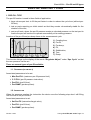
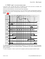
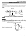
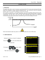
1. PRINCIPLE
Problem:
Is the pressure drop occurring during the test time due
to a leak or a transient effect?
The test environment is not always ideal for the
measurement of pressure drops. There are several
momentary events (ex: temperature or volume
variations...) that can influence the measurement.
They are called transient effects.
Press
Pressure
drop
Fill
Stab.
Test
Dump Time
To avoid any interference, it is possible to increase the stabilization time to obtain the ideal
measurement conditions during the test phase. However, increasing the stabilization time for
each test may not be acceptable for optimal production speed.
Operational principle:
The principle consists of measuring the pressure variations caused by transient phenomena through
the use of a learning cycle and then removing these variations from the final test result for a part.
Three ATR (Attenuated Transient Reduction) functions are available: ATR0, ATR1, ATR2 and
ATR3. ATR1 and ATR2 are different because of their learning cycles.
1.1. ATR0
The initial value of the transient is known. Parameters must be set manually.
The ATR may only be used on parts that have identical behaviors during the test, in other
words, parts that have an identical transient.
Associated parameters to be set are:
¾ Start (Initial value of the transient),
¾ Transient (actual, non modifiable value of the transient),
¾ Percentage drift (Percent of the reject level, the measurements used for transcient
calculation are less than this value).
¾ Drift (Drift tolerance on acquisition of the transient, as a % of the Reject level).
The “start” value is saved and subtracted from the final result of the tests.
Version 1.04a
User guide ATEQ 6th series Page 1/6
Sheet #607u – ATR 0 – 1 – 2 – 3 function
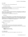
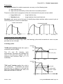
1.2. ATR1
The value of the transient is unknown. A special learning cycle must be carried out.
The learning cycle for this function must be carried out
on a known good part.
Pressure
The instrument performs a normal test cycle and
considers that the pressure variation measured at the
end of the cycle is the transient. This value is saved and
subtracted from the final result of subsequent tests. Its
value is recalculated at each measurement cycle.
Reasoning: the part is a good part therefore the
pressure drop measured is the transient.
Fill
'P = Transient
Stab
Test
Dump
Time
Associated parameters to be set:
¾ Start (Initial value of the transient),
¾ Transient (actual, non modifiable value of the transient),
¾ Percentage drift (Percent of the reject level, the measurements used for transcient
calculation are less than this value).
¾ Drift (Drift tolerance on acquisition of the transient, as a % of the Reject level).
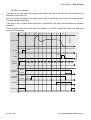
1.3. ATR 2
The value of the transient is
not known but the possible
leak of the part is taken into
account when the transient
value is computed during the
special cycle.
Pressure
Fill
'P 1
Stab
Test1
'P 2
Wait time 5 x test time
Test2 Dump Time
At the end of test time 1, the ATEQ saves the pressure variation 'P1, function of the transient
and the leak if there is one.
'P1 = Leak + Transient
Following the waiting time (equivalent to 5 times the normal test time), we consider that the
transient phenomena has disappeared. During the second test time, the ATEQ instrument
measures a second pressure drop 'P2 which corresponds to the leak.
'P2 = Leak
By taking these two pressure variations, we can calculate the transient.
'P1 - 'P2 = (Leak + Transient) - Leak = Transient
It is this transient which will be subtracted from the leak measurement of the following cycles.
Through the use of the ATR, the ATEQ instrument is able to differentiate a Pass part from a Fail
part without being influenced by the transient effects whilst keeping a short stabilization time.
Version 1.04a
User guide ATEQ 6th series Page 2/6
Sheet #607u – ATR 0 – 1 – 2 – 3 function
Associated parameters to be set:
¾ Start (Initial value of the transient),
¾ Transient (actual and non modifiable value of the transient),
¾ Percentage drift (Drift tolerance on acquisition of the transient, as a % of the reject level).
When a parameter is modified but no learning cycle has started, an ATR error occurs. The
Alarm and End of Cycle outputs are activated.
A learning cycle may be carried out when the measured value is greater than the reject level.
After the learning cycle, the Pass and End of Cycle outputs are activated.
1.4. ATR3
This is the same as the ATR2. The difference is, if the measurement result is negative, then the
measurement absolute value is displayed.
Associated parameters to be set:
¾ Start (Initial value of the transient),
¾ Transient (actual, non modifiable value of the transient),
¾ Percentage drift (Percent of the reject level, the measurements used for transcient
calculation are less than this value).
¾ Drift (Drift tolerance on acquisition of the transient, as a % of the Reject level).
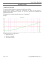
1.5. TRANSIENT DRIFT
Due to the evolution of the test conditions (temperature variations...), the value of the transient
can vary through time. It is therefore necessary to track its evolution.
To avoid having to carry out learning cycles too often, the ATEQ instrument saves the last ten
values of parts considered as very good (result close to 0) and recalculates the transient using
the average value.
Parts are considered as very good when their leak rate is lower than the “percentage drift” value
of the reject level. This value can be modified between 0 % and 100 %.
Transient
¦ of the value of the last 10 very good parts
10
The transient attenuation (ATR) can only be used on parts that behave in a very similar
way during the test, in other words, parts that have similar transients.
When the batch of parts changes or when the production is stopped for a certain time, it
is necessary to carry out a new learning cycle, as the transient will change.
The ATR error appears if the difference between the transient and the initial (start) value is
greater than the reject level.
The transient can evolve one way or the other; therefore it is preferable to have identical Test
and Reference reject levels.
Version 1.04a
User guide ATEQ 6th series Page 3/6
Sheet #607u – ATR 0 – 1 – 2 – 3 function
2. PROCEDURE
Activate the function or check if it checked.
2#4#/ 2T(70%6+10
ŹATR0
More functions…
Press the
: No
key, the cursor slide to the
right hand.
Note: Selecting an ATR function cancels the
others, only one ATR function by program.
2#4#/ 2T(70%6+10
By using the
"Yes" and validate with the
arrows, select
ŹATR0
More functions…
: Yes
Ż
key.
2#4#/2T(70%6#6
The parameters are displayed, enter the
values.
Version 1.04a
Ź Start
Transient
% Drift
DRIFT
:
:
:
:
0
0
20
100
User guide ATEQ 6th series Page 4/6
Sheet #607u – ATR 0 – 1 – 2 – 3 function
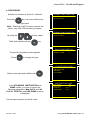
3. SPECIAL CYCLE
Example with ATR1 (the other processes are the same for ATR2 and ATR3.
From the main menu, enter the special cycle
menu.
52'%;%.'
none
Regul. adjust
Infinite fill
Piezo auto zero
Ź ATR Learning Cycle
In the special cycle menu, select
"ATR Learning Cycle".
For some ATR, others parameters are to be
informed.
/'0752'%;%.'
T. ATR2
CONFIRM
:
0.0 s
Ż
Adjust the value, the go in front of "CONFIRM"
and press
.
52'%;%.'
Remind: it's important to have a pass part
plugged.
ATR
Pr 001
The cycle screen is displayed confirming the
special cycle selection. Press the
"START CYCLE"
LEAK TEST
key.
The learning special cycle carry out the
following steps:
600.0
mbar
ATR TIME
050
Pa
22
FILL / STABILIZATION / TEST et
CHECK TEST
Pr1
Pa
1.4 s
600.0
mbar
At the end of the special cycle, the result must
be pass (OK).
50
Pa
22
Pr1
Version 1.04a
OK
Pa
READY
User guide ATEQ 6th series Page 5/6
Sheet #607u – ATR 0 – 1 – 2 – 3 function
It's possible to check the recorded parameters
by the special cycle by pressing the
T(70%6%*'%-6'5
Ź Measure :
Max value :
% Drift
CheckTime :
90.0
100.0
: 20
5.0 s
key just after the special cycle end.
Note: it's possible to modify these parameters.
At each test time the device displays the
"ATR MODE" message to inform the ATR
computing of the device.
600.0
mbar
TEST
050
Pa
ATR MODE
Pr1
1.4 s
0.0
mbar
If theATR special cycle is not carried out
before, the alarm message
"Do Learning Cycle ATR" is triggered.
Do Learning Cycle
ATR
Pr1
Version 1.04a
ALARM
READY
User guide ATEQ 6th series Page 6/6
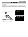
Sheet #608u – Pre-fill and fill types
PRE-FILL AND FILL TYPES
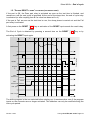
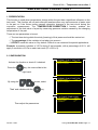
1. PRE-FILL TYPE
The pre-fill function is used in three fields of application:
¾ large volume part test: to fill the part faster in order to reduce the cycle time (without prefill time),
¾ test on parts requiring an initial stretch so that they remain volumetrically stable for the
duration of the test,
¾ part proof tests, where the pre-fill pressure exerts an elevated pressure on the test part to
ensure the part will continue to operate successfully at its working pressure.
TEST
PRESSURE
Insertion of the pre-fill and pre-dump times in the measurement cycle.
1
2
3
4
5
6
7 TIME
1)
2)
3)
4)
5)
6)
7)
Coupling time,
Pre-fill,
Pre-dump,
Fill,
Stabilization,
Test,
Dump.
This function brings up the display of the words “Regulator Adjust” under “Spe. Cycle” so that
the new pressure can be set.
There are several types of pre-fill available:
1.1. STANDARD (BY DEFAULT)
Associated parameters to be set:
¾ Max Pre-FILL (maximum pre-fill pressure limit),
¾ C. P-FILL (pre-fill pressure instruction).
¾ Pre-FILL (pre-fill time),
¾ Pre-DUMP (pre-dump time).
1.2. INSTRUCTION
When the pressure reaches the instruction the device runs the following step else it still filling
until the end of the pre-fill time.
Associated parameters to set:
¾ Set Pre-Fill (instruction/target value),
¾ Pre-FILL (pre-fill time),
¾ Pre-DUMP (pre-dump time).
Version 1.04a
User guide ATEQ 6th series Page 1/4
Sheet #608u – Pre-fill and fill types
1.3. BALLISTIC
This fill mode enables fluctuation in the air pressure (filling parts with a high level of
deformation) and in particular allows the Max Pre-Fill limit to be exceeded without the cycle
stopping and an error message being displayed.
Associated parameters to be set:
¾ Set PreFILL (Pre fill pressure instruction).
¾ Pre-FILL (pre-fill time),
¾ Pre-DUMP (pre-dump time).
1.4. FILL RAMP (ELECTRONIC REGULATOR ONLY)
This fill mode applies only to electronic regulators and will allow the part to be slowly filled to the
Pre-Fill pressure in a linear manner over the duration of the fill time.
¾ Max PreFILL. (maximum pre-fill pressure limit),,
¾ Set PreFILL (Pre fill pressure instruction).
¾ PRE-FILL. (pre-fill time),
¾ PRE-DUMP (pre-dump time).
1.5. PRE-FILL REGULATOR
This function applies when two regulators are installed in the instrument allowing the choice of
which regulator is to be used for pre-fill (1 or 2).
Version 1.04a
User guide ATEQ 6th series Page 2/4
Sheet #608u – Pre-fill and fill types
2. FILL TYPE
This function provides a choice of these possible types of fill.
2.1. STANDARD (BY DEFAULT)
The default setting - during Fill time, the Fill valve opens allowing the regulator to supply air to
the part at the regulator’s set pressure.
Associated parameters to be set: Set FILL (fill pressure instruction).
2.2. INSTRUCTION (SET)
This mode allows a Mechanical regulator to fill the part to a value less than the regulator’s set
pressure. When the pressure sensor in the instrument reads the Set Fill value, the Fill-Valve is
closed and the test sequence continues.
Associated parameters to set: Set Fill (instruction/target value),
2.3. BALLISTIC
This fill mode enables fluctuation in the air pressure (filling parts with a high level of
deformation) and in particular allows the maximum fill limit to be exceeded without the cycle
stopping and an error message being displayed. However, once the test sequence enters the
stabilization phase, the test pressure must be within the limits defined by Max Fill and Min Fill.
Associated parameters to set: Set Fill (instruction/target value),
2.4. RAMP (ELECTRONIC REGULATOR ONLY)
The device carries on a linear fill.
FILL ADJUST
2.5. FILL ADJUST
This function appears only with a device with an electronic regulator built in.
In case of part hard to fill, this function allows automatically correct instruction to reach precisely
the programmed pressure target.
Associated parameters to set:
¾ Set FILL (fill pressure instruction).
¾ TIME ADJ (extra time for correction).
3. FILL REGULATOR
This function provides a choice of which of two regulators to use for the fill (1 or 2).
Version 1.04a
User guide ATEQ 6th series Page 3/4
Sheet #608u – Pre-fill and fill types
4. PROCEDURE
Activate the function or check if it checked.
2#4#/ 2T(70%6+10
ŹPRE-FILL
More functions…
Press the
: No
key, the cursor slide to the
right hand.
Note : Selecting an ATR function cancels the
others, only one ATR function by program.
2#4#/ 2T(70%6+10
By using the
arrows, select
"Yes" and validate with the
PRE-FILL
More functions…
: Yes
Ż
key.
2T(70%624'Ä(+..
Ź PreFILL
:
PRE FILL REG :
The pre-fill cofiguration menu appears.
Press
STANDA
2
to change the type.
(70%624'Ä(2TG(+.
Select a new type and validate with
.
ŹSTANDARD
INSTRUCTION
BALISTIC
FILL RAMP
0%624'Ä(5GV2TG(+.
In the STANDARD, INSTRUCTION and
RAMP modes, you have to inform the
following parameters: Max PreFIL and Set
PreFILL, PRE-FILL and PRE-DUMP times as
it displayed.
ŹMax preFIL
Set PreFIL
PRE-FILL
PRE DUMP
:
:
:
:
0.0
0.0
0.0 s
0.0 s
Use the same process for the fill mode.
Version 1.04a
User guide ATEQ 6th series Page 4/4
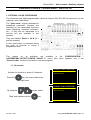
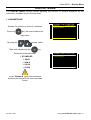
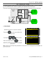
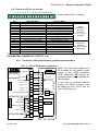
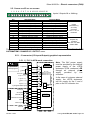
Sheet #609u – Valves codes / Auxiliary outputs
VALVES CODES / AUXILIAIRY OUTPUTS
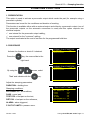
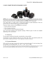
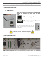
1. OPTIONAL VALVE CODE BOARD
The instrument has eight programmable electrical outputs (24V DC/100 mA maximum) on the
(optional) valve code board.
The “Valve code” outputs dedicated to
predefined pneumatic functions are
identified by the associated function’s
name: Stamping, automatic connector,
etc… If they are not associated to a
function but are available to the
operator.
They are labeled: Ext N or Int N (N =
position number).
A free used output is activated during
the cycle, in continue or during a
programmed time..
The options for its activation are available in the CONFIGURATION /
AUTOMATISM / OUTPUT CONFIG / VALVE C. menu (this menu appears only if the
"Valves Codes" function is activated in one test program).
1.1. PROCEDURE
2#4#/ 2T(70%6+10
Activate the function or check if it checked.
Press the
Ź VALVES CODES
More functions…
: No
key, the cursor slide to the
right hand.
2#4#/ 2T(70%6+10
By using the
"Yes" and validate with the
Version 1.04a
arrows, select
Ź VALVES CODES
More functions…
: Yes
Ż
key.
User guide ATEQ 6th series Page 1/4
Sheet #609u – Valves codes / Auxiliary outputs
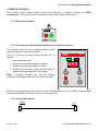
(70%68#.8'%1&'
The validation menu of each output, external
and internal is displayed.
Activate one or both output codes by validate
with "Yes".
If the output is configured on
"PROGRAMMED" the activation times have to
be informed.
DELAY EXT : delay for the output activation
after start test cycle.
TIME EXT : activation time of the output.
Ź Ext.
Ext.
Ext.
Ext.
Ext.
Ext.
Int.
Int.
1
2
3
4
5
6
1
2
:
:
:
:
:
:
:
:
Yes
No
No
No
No
No
No
No
(10%6%1&'58#00'
Ź Ext.
1
RETARD EX:
DUREE EXT:
Ext.
2
Ext.
3
Ext.
4
Ext.
5
Ext.
6
: Oui
0.0 s
0.0 s
: Non
: Non
: Non
: Non
: Non
%10(+#761/%8#00
To configure "Valve Code" output mode go in
the "CONFIGURATION/AUTOMATISM/
OUTPUTS CONFIG./ VALVE C.
Ź Ext.
Ext.
Ext.
Ext.
Ext.
Ext.
Int.
Int.
1
2
3
4
5
6
1
2
:
:
:
:
:
:
:
:
CYCLING
PROGRAMMED
CONTINUOUS
CYCLING
CYCLING
CYCLING
CYCLING
CYCLING
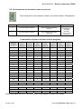
¾ CYCLING: the output is activated during the test cycle.
¾ CONTINUOUS: the output is continuously activated.
¾ PROGRAMMED: the output is activated during a programmed time.
Version 1.04a
User guide ATEQ 6th series Page 2/4
Sheet #609u – Valves codes / Auxiliary outputs
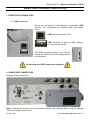
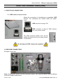
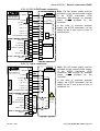
2. 24V AUXILIARY OUTPUTS
On the instrument main board there are four programmable electrical outputs (24V DC / 100 mA
maximum / output).
Unlike the valve code outputs, the
auxiliary outputs reserved for a
pneumatic function are identified by the
name of the function: stamping,
automatic connector, etc.
They are not associated to a function but
are available to the operator.
They are labeled Aux N (N = position
number).
Associated parameters to be adjusted:
Auxiliary 1, Auxiliary 2, Auxiliary 3,
Auxiliary 4.
2.1. PROCEDURE
2#4#/ 2T(70%6+10
Activate the function or check if it checked.
Press the
Ź24V OUTPUTS
More functions…
: No
key, the cursor slide to the
right hand.
2#4#/ 2T(70%6+10
By using the
"Yes" and validate with the
arrows, select
Ź24V OUTPUTS
More functions…
: Yes
Ż
key.
(70%68176276
The validation menu of each output, external
and internal is displayed.
Ź AUX
AUX
AUX
AUX
1
2
3
4
:
:
:
:
Yes
No
No
No
Activate one or both auxiliary output by
validate with "Yes".
Version 1.04a
User guide ATEQ 6th series Page 3/4
Sheet #609u – Valves codes / Auxiliary outputs
%10(+#761/%8#00
To configure "Auxiliary" output mode go in
the "CONFIGURATION/AUTOMATISM/
OUTPUTS CONFIG./ I/O.
Ź AUX
AUX
AUX
AUX
1
2
3
4
:
:
:
:
EN CYCLE
PROGRAMME
PERMANENT
EN CYCLE
¾ CYCLING: the output is activated during the test cycle.
¾ CONTINUOUS: the output is continuously activated.
¾ PROGRAMMED: the output is activated during a programmed time.
Note: some auxiliaries outputs can not be available and are attributed for others functions,
example: automatic connector, stamping etc.
Version 1.04a
User guide ATEQ 6th series Page 4/4
Sheet #610u – End of cycle
END OF CYCLE
This function enables the choosing of one of the different end of cycle depending on the
configuration of the instrument (connection to a PLC…).
1. RELAY SEQUENCING RELATED TO DIFFERENT END OF CYCLE
In order to interface the ATEQ with its environment (PLC, PC …), the following timing charts
supply the details of the sequencing of the electrical outputs (relay board on the J3 connector)
and pneumatic outputs (automatic connectors), depending on the commands entered on the
front panel or through the J3 connector (START, RESET).
Legend
A
Coupling time A
B
Coupling time B
P-F
Pre-fill time
P-D
Pre-dump time
F
Fill time
S
Stabilization time
Unspecified time occurring between the programmed test time and the
#
pressing of the reset
T
Test time
D
Dump time
START
Press the
key.
key on the front panel or short pins 2-3 on the relay
board connector.
RESET
Press the
key on the front panel or short pins 1-2 on the on
the relay board connector.
Automatic
Connector
Active (high level): the pneumatic output is active (air output).
Inactive (low level): the pneumatic output is inactive (no air output).
PASS or
FAIL
Fail part or Pass part relay on the on the relay board connector
EoC
End of cycle relay on the relay board connector
t mini
Minimum time to accept an entry 50 ms on connector on the relay
board.
Actual times are not those displayed but those on the print-out.
Version 1.04a
User guide ATEQ 6th series Page 1/7
Sheet #610u – End of cycle
1.1. "AUTOMATIC RESET" CYCLE END
If the part is OK, the Pass part relay will be activated as soon as the test ends and remain so
until the start of the following cycle. Following the dump time, the end of cycle relay is activated.
If the part is fail, the Fail part relay is activated as soon as the test is completed. The instrument
automatically dumps and sends an end of cycle signal. A new cycle can then be started.
P-F
P-D
F
S
T
D
Test cycle
A
PRESSURE
t
t
t mini
Reset
t
Program
Number
t mini
Orders actions
t mini
START
t
Automatic
Connector A
Automatic
connector B
Active
B time
Inactive
Active
t
B time
Inactive
t
Pass part or
Fail part
t
End of cycle
t
The active program is the one selected before starting up. It remains active even if the program
inputs on the connector are no longer activated. This selection can only be modified during the
inter cycle period.
To return to program 1, when a cycle is not in progress, press any program selection inputs.
Version 1.04a
User guide ATEQ 6th series Page 2/7
Sheet #610u – End of cycle
1.2. ENDING A CYCLE WITH THE RESET KEY ("AUTOMATIC RESET" CYCLE END)
P-F
P-D
F
D
Test cycle
A
PRESSURE
t
t
t mini
Reset
t
Program
number
t mini
Orders actions
t mini
START
t
Automatic
connector A
Automatic
connector B
Active
B time
Inactive
Active
t
B time
Inactive
t
Pass part or
fail part
t
End of cycle
t
The active program is the one selected before starting up. It remains active even if the program
inputs on the connector are no longer activated. This selection can only be modified during the
inter cycle period.
To return to program 1, when a cycle is not in progress, press any program selection inputs.
Version 1.04a
User guide ATEQ 6th series Page 3/7
Sheet #610u – End of cycle
1.3. "RESET + DUMP" CYCLE END (AUTOMATIC DUMP)
If the part is OK, the Pass part relay is activated as soon as the test time is finished, and
remains so (only in position 2) until the next cycle is started.
At the end of the dump time, the end of cycle relay is activated.
If the part is Fail, as soon as the test time is over, the Fail part relay is activated and remains so
until the end of the cycle. The dump is then carried out. The cycle can be ended by pressing the
RESET
key.
P-F
P-D
F
S
T
D
Test cycle
A
PRESSURE
t
t
t mini
Reset
t
Program
number
t mini
Orders actions
t mini
START
t
automatic
connector A
Active
B time
Inactive
Active
Automatic
Connector B Inactive
t
B time
t
Fail part
t
End of cycle
t
The active program is the one selected before starting up. It remains active even if the program
inputs on the connector are no longer activated. This selection can only be modified during the
inter cycle period.
To return to program 1, when a cycle is not in progress, press any program selection inputs.
Version 1.04a
User guide ATEQ 6th series Page 4/7
Sheet #610u – End of cycle
1.4. "FILL" CYCLE END
If the part is OK, the Pass part relay is activated at the end of the test time and remains so till
the start of the next cycle.
At the end of the dump time, the end of cycle relay is activated (or at the end of coupling time B
if a value has been set for it).
If the part is fail, as soon as the test time is finished the Fail part relay becomes and remains
activated.
The instrument waits for a reset from the operator or the PLC to start the dump time and send
the end of cycle signal.
P-F
P-D
F
S
T
#
D
Test cycle
A
PRESSURE
t
t mini
START
Orders actions
t
t mini
Reset
t
program
number
t mini
t
automatic
Connector A
automatic
Connector B
Active
B time
Inactive
Active
t
B time
Inactive
t
Fail part
t
End of cycle
t
Version 1.04a
User guide ATEQ 6th series Page 5/7
Sheet #610u – End of cycle
1.5. "DOUBLE RESET + DUMP" CYCLE END (AUTOMATIC DUMP)
If the part is OK, the Pass part relay is activated as soon as the test time is finished, and
remains so until the next cycle is launched. At the end of the dump time, the end of cycle relay
is activated (or after coupling time B if a value has been set for it).
If the part is Fail, as soon as the test time is over, the dump phase is carried out and the Fail
part relay is activated
A first press on the RESET
key or activation of the RESET input cancels the result relay.
The End of Cycle is obtained by pressing a second time on the RESET
key or by
activating the RESET input again.
P-F
P-D
F
S
T
D
Test cycle
A
PRESSURE
t
t
t mini
RESET
t
Program
n°
t mini
Control actions
t mini
START
t
Auto
connector A
Active
Time B
Inactive
Active
Auto
connector B Inactive
t
Time B
t
FAIL part
t
End of Cycle
t
The active program is the one selected before starting up. It remains active even if the program
inputs on the connector are no longer activated. This selection can only be modified during the
inter cycle period.
Version 1.04a
User guide ATEQ 6th series Page 6/7
Sheet #610u – End of cycle
2. PROCEDURE
Activate the function or check if it checked.
Press the
2#4#/ 2T(70%6+10
ŹEND OF CYCLE
More functions…
: No
key, the cursor slide to the
right hand.
2#4#/ 2T(70%6+10
By using the
"Yes" and validate with the
arrows, select
Ź END OF CYCLE
More functions…
: Yes
Ż
key.
(70%6'0&1(%;%.
Then select the end of cycle mode you want
(validate with "Yes").
Version 1.04a
Ź AUTO RESET
DUMP + RESET
FILL TIME
DERIVE
:
:
:
:
No
No
No
No
User guide ATEQ 6th series Page 7/7
Sheet #611u – Mini Valve
MINI VALVE
This function is dedicated to small part applications (volume below 10 cm3) and has a base time
of 0.01s instead of 0.1 s.
The programming of an ATEQ with a mini valve is identical to the programming of the standard
ATEQ.
Parameter to be set is: A-Z Diff (differential Auto Zero). This time can be reduced as long as the
obtained values are stable and repeatable.
1. PROCEDURE
2#4#/ 2T(70%6+10
Activate the function or check if it checked.
Press the
ŹMINI-VALVE
More functions…
: No
key, the cursor slide to the
right hand.
2#4#/ 2T(70%6+10
By using the
"Yes" and validate with the
arrows, select
Ź MINI-VALVE
More functions…
: Yes
Ż
key.
T(70%6/+0+Ä8#.8
Ź Diff A-Z
:
0.50 s
Adjust the differential Auto-Zero value if
needed, the default value is proven stable
(500 ms).
Version 1.04a
User guide ATEQ 6th series Page 1/1
Sheet #612u – Rework limits
REWORK LIMITS
This option offers the option of two reject levels: normal reject level (the fail part cannot be repaired)
and a re-workable reject level (the part is fail but may be reworked to become acceptable). This
option is often used in casting processes, when parts may be treated via impregnation.
REFERENCE
FAIL LEVEL
0
PARTS
PASS
Example
REFERENCE FAIL
REWORK LEVEL
0
TEST FAIL LEVEL
PARTS
PARTS
RE-WORKABLE
TEST FAIL
REWORK LEVEL
10
FAIL
20
0 TO 10 OF THE PARTS ARE GOOD
10 TO 20 OF THE PARTS ARE RE-WORKABLE
ABOVE 20 THE PARTS ARE NOT RE-WORKABLE
The associated parameters to be set are: Test REWORK and Ref. REWORK.
For re-workable parts, with multi-head configuration on the central unit or on the heads
themselves, the Pass (OK) and Fail (NOK) outputs are both activated simultaneously.
When the recoverable reference reject value is zero, the program uses the
symmetrical opposite sign value of the recoverable test reject (example: if the
recoverable test reject is 10 Pa, then with the recoverable reference reject value set
at zero, the program assumes the recoverable reference reject to be -10 Pa).
1. PROCEDURE
2#4#/ 2T(70%6+10
Activate the function or check if it checked.
Press the
ŹREWORK LIMIT
More functions…
: No
key, the cursor slide to the
right hand.
2#4#/ 2T(70%6+10
By using the
"Yes" and validate with the
Version 1.04a
arrows, select
Ź REWORK LIMIT
More functions…
: Yes
Ż
key.
User guide ATEQ 6th series Page 1/2
Sheet #612u – Rework limits
Adjust the Rework values for the Test side
and the Reference side.
(70%64'914-.+/+
Ź TestREWORK :
Ref.REWORK :
0
0
Remind: if the Reference value is set to 0, it
assumes the same value as the Test with the
opposite sign.
100.0
mbar
When the part is "Reworkable", the display is
like the following one.
50
Pa
27
Pr1
Version 1.04a
REWORKABLE
Pa
READY
User guide ATEQ 6th series Page 2/2
Sheet #613u – Sealed components
SEALED COMPONENTS
1. PRESENTATION
The sealed component mode is designed for leak measurement on sealed parts. The solution is
to enclose the part in a sealed bell, to fill this bell and to measure the pressure drop in the part.
Principle:
The external volume is connected to the pressurization port of the instruments valve.
Volume fill:
The external volume (V1) is filled to a pressure P1.
Part transfer:
The previously-filled internal volume (P1.V1) is opened to the chamber volume (V2), obtaining
P2.V2. Through monitoring, the instrument detects large leaks. If the part has a large leak, the
final pressure is lower than with a sealed part. Two limits (min. and max.) given as a percentage
of the P1/P2 ratio are used to detect large leaks.
The solution is based on the relationship: P1.V1 = P2.V2
Pressure
P1
P2
If the part is leaking, the final volume will be
greater so the final pressure will be lower.
LARGE LEAK
Internal fill
volume V1 for
the ATEQ
instrument
Version 1.04a
Transfer
Time
User guide ATEQ 6th series Page 1/8
Sheet #613u – Sealed components
Test modes
The ATEQ dedicated for sealed components can carry out the following tests:
1. large leak test only,
2. large leak test followed by a finer leak test at a smaller pressure.
These two modes can be programmed from the instrument's front panel and are called:
x
Large leak mode
:
Large leak test only,
x
Standard mode
:
Large leak test, then small leak test.
Standard mode carries out a first cycle to identify large leaks and then adds a second cycle at
nominal pressure to check for small leaks.
LARGE LEAK MODE
Fill
Trans
Dump
STANDARD MODE
Fill
Trans
Fill
Stab
Test Dump
Carrying out the cycles and settings
For the instrument to detect large leaks, two learning cycles must be carried out: one on a pass
part and one on a fail part.
Learning cycles:
Pressure
"PASS part" learning cycle: this cycle is
compulsory before testing.
This P1 and P2 learning cycle
automatically calculates and identifies the
value of the pass part together with the
maximum and minimum limits (+/- 5 %
modifiable).
P1
Max. limit (+5 %)
P2
Min. limit (-5%)
Fill
Trans
Time
Pressure
P1
"FAIL part" learning cycle: this cycle is
not compulsory. It calculates the actual
minimum limit in relation to a fail part by
taking an average between the value of a
pass part and that of a fail part
Good part
Recalculated
limit(PB + PM)/2
Bad part
Fill
Version 1.04a
Transfer
Time
User guide ATEQ 6th series Page 2/8
Sheet #613u – Sealed components
The instrument allows for variations in input pressure. This is why the maximum
and minimum parameters vary for each cycle.
At the end of a learning cycle (fill of the volume, volume transfer, dump) the Pass part and
End of Cycle outputs are activated. If the volume is greater (large leak), the Fail Part and
End of Cycle outputs are activated. If the volume is reduced (problem with the fixture) the
Alarm and End of Cycle outputs are activated.
Learning cycles for pass parts and parts with a large leak are accessed through the main menu
under special cycles.
Test cycles cannot be carried out unless learning cycles have previously been carried out.
Version 1.04a
User guide ATEQ 6th series Page 3/8
Sheet #613u – Sealed components
2. LE 3 TYPES OF SEALED COMPONENTS
Because of the device hard configuration is different following the sealed components type, the
type must be choose at the device order.
2.1. SEALED COMPONENTS 1
Standard version with the bell under pressure. See the presentation above.
Steps:
1) Insulation of the test part.
2) Volume fill.
V3 F5 valve
V2
FILL
TEST
3) Volume transfer to the test part.
V2
V1
DUMP
REF
Pressurization
Volume
2.2. SEALED COMPONENTS 2
Reverses quick sealed components.
1) Filling of the test part.
2) Transfer of the test part to the volume.
V3 F5 valve
V2
FILL
TEST
V2
V1
DUMP
REF
AUX1
V4
Pressurization
Volume
ATM
Version 1.04a
User guide ATEQ 6th series Page 4/8
Sheet #613u – Sealed components
2.3. SEALED COMPONENTS 3
Reverses quick sealed components high accuracy.
1) Filling of the test part, of the volume and pressurization
volume.
2) Insulation of the test part.
V3 F5 valve
V2
FILL
TEST
3) Dumping of the volume and the pressurization volume.
V1
4) Stop dump (volumes).
5) Transfer from the test part to the volumes.
DUMP
AUX1
ATM
Version 1.04a
V2
REF
V4
Pressurization
Volume
User guide ATEQ 6th series Page 5/8
Sheet #613u – Sealed components
3. CONFIGURATION
2#4#/ 2T(70%6+10
Activate the function or check if it checked.
Press the
ŹSEALED PART
More functions…
: No
key, the cursor slide to the
right hand.
2#4#/ 2T(70%6+10
By using the
"Yes" and validate with the
arrows, select
SEALED PART
More functions…
: Yes
Ż
key.
(70%65'#.'&%1/2
Ź STANDARD
LARGE LEAK
Select the mode: "STANDARD" or
"LARGE LEAK".
2#4#/2T
When selected, two parameters are added to
the program: "Fill volume time" and
"Transfer time" that you have to inform (the
transfer parameter can't be less than 0.5s).
Version 1.04a
Ź TYPE : LEAK TEST
COUPL. A
:
0.0
FILL VOL
:
0.5
TRANSFERT :
0.5
FILL TIME :
1.0
STAB TIME :
2.0
TEST TIME :
1.5
DUMP TIME :
0.5
s
s
s
s
s
s
s
User guide ATEQ 6th series Page 6/8
Sheet #613u – Sealed components
4. SEALED COMPONENT SPECIAL CYCLE LEARNING
For sealed components, learning cycles for Pass and Fail must be performed so that the
instrument calculates the parameters.
As the learning cycles have not been carried out, the device cannot run test cycles.
¾ Sealed PASS Part Learn: This learning cycle calculates and identifies the value of the pass
part together with the maximum and minimum limits (+/- 5 % modifiable). This cycle is
compulsory for sealed component mode.
¾ Sealed FAIL Part Learn: this cycle allows learning the pressure parameters for a fail part
by taking an average between the value of a pass part and that of a fail part. This cycle is
not compulsory.
From the main menu, enter the special cycle
menu.
52'%;%.'
none
Regul. adjust
Infinite fill
Piezo auto zero
Ź Sd PASS Prt Learn
Sd FAIL Prt Learn
In the special cycle menu, select
"Sd PASS Prt Learn".
Remind: it's important to have a pass part
plugged.
52'%;%.'
The cycle screen is displayed confirming the
special cycle selection. Ensure that a pass
part is inside the chamber and run the special
Pr 001
cycle by pressing the START
Sd Part
LEAK TEST
key.
REMPLISSAGE V
The learning cycle is running with the following
steps:
000
VOLUME FILL, VOLUME TRANSFERT and
TEST.
Pr 01
Pa
1.4 s
100.0
mbar
050
Pa
000
The final result must be Pass (OK).
Pr 01
Version 1.04a
OK
Pa
0.0 s
User guide ATEQ 6th series Page 7/8
Sheet #613u – Sealed components
The finalised sealed component parameters
can be reviewed and modified by the user in
the functions menu of the program or by
pressing the
5'#.'&%1/2
ŹMin Level
MEASURE
Max Level
:
:
:
0.010
0.001
0.020
key.
Do the same process for the FAIL PART
learning cycle (this cycle is optional) with a fail
part inside the chamber.
100.0
mbar
If the sealed part special cycle is no carried
out before, the alarm message
"Do Learning Cycle" is displayed.
Do Learning Cycle
SEALED PART
Pr 01
Version 1.04a
ALARM
READY
User guide ATEQ 6th series Page 8/8
Sheet #614u – N Tests
N TESTS
1. PRESENTATION
N test function: repetition of the test when the result is near the reject level.
It consists in conditionally repeating the test time to optimize the cycle time (rapid decision
making on parts with large leaks or very good parts).
The bad parts (bad but close to the reject level) are subject to a longer test.
The instrument repeats the test time 3 times maximum.
CYCLE PROGRESS:
: 0 < Measured value < Reject = Good Part (standard cycle).
Step 1:
Reject < Measured value < Tolerance A = Run Test time
Again.
Measured value > Tolerance A = Bad Part.
0 < Measured value < Reject = Bad Part (standard cycle).
Step 2:
Reject < Measured value < Tolerance B = Run Test time
Again.
Measured value > Tolerance B = Bad Part.
Step 3 (standard step) :
0 < Measured value < Reject = Good Part (standard cycle).
Measured value > Reject = Bad Part.
This function cannot be enabled in addition to the following functions: ATR; Operator Test;
Burst Test; Temperature Correction; Blockage Test). During the CAL learning cycle CAL, this
function is not activated.
Version 1.04a
User guide ATEQ 6th series Page 1/2
Sheet #614u – N Tests
2. PARAMETRAGE
2#4#/ 2T(70%6+10
Activate the function or check if it checked.
Press the
ŹN TEST
More functions…
: No
key, the cursor slide to the
right hand.
2#4#/ 2T(70%6+10
By using the
"Yes" and validate with the
arrows, select
N TEST
More functions…
: Yes
Ż
key.
/ 2T(70%606'56
Ź Tolerance A
Tolerance B
:
:
000 %
000 %
Adjust the tolerances values A and B as a
percent of the reject value.
Version 1.04a
User guide ATEQ 6th series Page 2/2
Sheet #615u – Reference Volume
REFERENCE VOLUME
1. PRESENTATION
The program uses the programmed test volume to measure the normal flow at the test port.
When the reference port volume is different the test port volume, it is possible to set parameters
for the exact value of the reference volume to obtain correct measurements in the event of
results displaying negative values.
This function may only be used with flow measurement units: cm3/min, cm3/s, cm3/h, mm3/s,
ml/s, ml/min or ml/h.
2. PARAMETRING
Ensure that the reject unit is a flow unit (see
above).
Activate the function or check if it checked.
Press the
2#4#/ 2T(70%6+10
ŹREF. VOLUME
More functions…
: No
key, the cursor slide to the
right hand.activée.
2#4#/ 2T(70%6+10
By using the
"Yes" and validate with the
arrows, select
REF. VOLUME
More functions…
: Yes
Ż
key.
(70%64'(81.7/
Ź Ref. VOL.:
15.00
Adjust the reference volume value.
2#4#/2T
This parameter is also available in the
program parameters under the name
"Ref. VOL.".
Version 1.04a
Pa DISPLAY
REJECT CALC
Volume UNIT
VOLUME
:
Ź Ref. VOL.
:
Test FAIL
:
Ref. FAIL
:
FUNCTION
: No
: Pa
: cm3
14.91
15.00
0.298
0.000
User guide ATEQ 6th series Page 1/1
Sheet #617u – Stamping function
STAMPING FUNCTION
1. PRESENTATION
This option is used to activate a pneumatic output which marks the part (for example using a
pneumatic cylinder).
Parameters can be set for the conditions and duration of marking.
This function is available either with an external output and either by a pneumatic output (one of
the pneumatic outputs on the automatic connectors is used) and this option requires two
electrical outputs:
9 one internal for the pneumatic output cabling,
9 one external for the "customer" cabling.
The output is activated at the end of test time for the programmed hold time.
2. PROCEDURE
2#4#/ 2T(70%6+10
Activate the function or check if it checked.
Press the
ŹSTAMPING
More functions…
: No
key, the cursor slide to the
right hand.
2#4#/ 2T(70%6+10
By using the
arrows, select
"Yes" and validate with the
STAMPING
More functions…
: Yes
Ż
key.
Adjust the stamping parameters.
DURATION = holding time.
Stamping conditions:
ALL RESULTS = all conditions,
PASS = good part,
TEST FAIL = bad part on the test,
REF FAIL = bad part on the reference,
2T(70%656#/2+0
Ź DUTATION :
0.0 s
ALL RESULTS
: No
PASS
: Oui
T FAIL
: No
R FAIL
: No
ALARM
: No
PRESSURE OUT : No
ALARM = alarm triggered,
P OUT OF LIMITS = pressure error.
Version 1.04a
User guide ATEQ 6th series Page 1/1
Sheet #618u – Temperature correction 1
TEMPERATURE CORRECTION 1
1. PRESENTATION
This function is used when temperature change within the part has a significant influence on the
test result. This function will not work after part washers when any trace amounts of water exist
in the part or if the fixture tooling causes volumetric changes in the test circuit during the
correction measurement. The TEMPERATURE CORRECTION 1 function enables the
adjustment of the leak value of a part by measuring pressure variation caused by the changing
temperature of the part.
There are two parameters to be set:
9 The test time during which the study (learning) of this pressure should be carried out.
9 The percentage of the variation to be taken into account.
9 OFFSET: leave this value to 0 by default. Difficult to use reserved for special applications.
Example: a pressure variation of 15 Pa during 2 test seconds, with a percentage of 60 %, will
apply a correction of 9 Pa on each test result (15 x 60%= 9).
2. CONFIGURATION
2#4#/ 2T(70%6+10
Activate the function or check if it checked.
Press the
ŹTEMP.CORR. 1
More functions…
: No
key, the cursor slide to the
right hand.
2#4#/ 2T(70%6+10
By using the
arrows, select
"Yes" and validate with the
TEMP.CORR. 1
More functions…
: Yes
Ż
key.
(70%66'/2%144
ŹCORRECTION
TEST TIME
OFFSET
: 100 %
: 0.0 s
:0
Then adjust the parameters.
Version 1.00a
User guide ATEQ 6th series Page 1/1
Sheet #620u – Peak hold
PEAK HOLD
1. PRINCIPLE
The peak hold mode is used to measure a part dynamically. The instrument measures the leak,
which can change at a given moment during the test. The instrument stores the greatest
pressure drop ('P/'t) and then displays it at the end of the test.
This function is important in circumstances where the test part changes during the test cycle.
The system checks the part for leaks in ǻP/ǻt throughout the change and the leak is measured
continuously. At the end of the test cycle, the instrument has stored the maximum
instantaneous leak (the greatest leak) recorded during the test and displays the result.
LEAK ǻP/ǻt
MAXIMAL
VALUE
MEASURED
0
TIME
Peak measurement mode only works in 'P/'t and excludes the use of ATR mode.
2. CONFIGURATION
2#4#/ 2T(70%6+10
Activate the function or check if it checked.
Press the
ŹPEAK HOLD
More functions…
: No
key, the cursor slide to the
right hand.
2#4#/ 2T(70%6+10
By using the
"Yes" and validate with the
Version 1.04a
arrows, select
PEAK HOLD
More functions…
: Yes
Ż
key.
User guide ATEQ 6th series Page 1/1
Sheet #621u – Sign
SIGN
1. PRESENTATION
The SIGN function enables reversing the sign (positive or negative) of the measurement result.
This function is useful in case of a vacuum application or indirect measurements as it allows the
display of a positive leak result.
2. PARAMETRAGE
2#4#/ 2T(70%6+10
Activate the function or check if it checked.
Press the
ŹSIGN
More functions…
: No
key, the cursor slide to the
right hand.
By using the
arrows, select
2#4#/ 2T(70%6+10
SIGN
More functions…
"Yes" and validate with the
: Yes
Ż
key.
The "Sign" function when validated, changes
the leak value sign.
Example: if the result is -004 Pa, the display
will be 004 Pa and vice versa.
Version 1.04a
User guide ATEQ 6th series Page 1/1
Sheet #622u – Filter
FILTER
1. PRINCIPLE
This function enables the slowing down of the sampling speed, by performing an average over
the set measurement time; this makes the displays value more readable during quickly
changing measurements value.
Cette fonction se justifie avec des unités liées au temps (Pa/s, cm3/s, l/min, etc.).
2. CONFIGURATION
2#4#/ 2T(70%6+10
Activate the function or check if it checked.
Press the
ŹFILTER
More functions…
: No
key, the cursor slide to the
right hand.
2#4#/ 2T(70%6+10
By using the
"Yes" and validate with the
arrows, select
FILTER
More functions…
: Yes
Ż
key.
2#4#/ 2T(70%6(+
FILTER
:
2.0 s
Ż
Adjust the Filter (time) parameter.
FILTER time: maximum duration of the
averaging of the measured result.
Version 1.04a
User guide ATEQ 6th series Page 1/1
Sheet # 623u –Special Cycles
SPECIAL CYCLES
1. PRESENTATION
To run, some functions needs one (or several) special cycle to be carry out, for further
information about this special cycle, see the functions sheet.
The availability will vary depending on what is checked in the extended menus or according to
the optional features built into the instrument.
The special cycle is carried out with the parameters of the active program.
2. RUN A SPECIAL CYCLE
From the main menu, enter the special cycle
menu.
52'%;%.'
Ź none
Regul. adjust
Infinite fill
Piezo auto zero
In the special cycle menu, select the special
cycle to carry out, then validate with
.
52'%;%.'
The cycle screen is displayed confirming the
special cycle selection. Press the
"START CYCLE"
key.
Regul.
Pr 001
LEAK TEST
%;%.'52'
To stop, press the
key. In some cycles
the stop is automatic.
For others special cycles, see the sheet
corresponding to the function.
PRESS = 600 mbar
SET PRESS LIMITS?
REGULATOR ADJ
The screen display the current program.
Pr 001
LEAK TEST
Version 1.04a
User guide ATEQ 6th series Page 1/2
Sheet # 623u –Special Cycles
3. SPECIAL CYCLES LIST
Special cycle
Function
¾ none:
No special cycle selected.
¾ Regulator 1 adjust:
Cycle to set regulator number 1.
¾ Regulator 2 adjust:
Cycle to set regulator number 2.
¾ Infinite fill:
Cycle to pressurize test part under for an infinite time.
¾ Piezo auto zero:
Cycle to perform a zero of the pressure transducer and
re-linearization of the electronic regulator.
¾ Sealed component
pass part:
learning,
¾ Sealed component
fail part:
learning,
Cycle to learn the pressure parameters for a good part in
case of a sealed component measurement. This learning
cycle is compulsory.
Cycle to learn the pressure parameters for a bad part in
case of a sealed component measurement.
¾ Calibration check by volume:
Cycle started manually by the operator to carry out
calibration check by volume with a good part.
¾ CAL learning:
Cycle to carry out learning in calibrated Pascal or
Pascal/sec mode on a known standard leak.
¾ CAL check:
Cycle for auto-diagnostics in calibrated Pascal mode (see
previous function) within a tolerance determined by
percentage limits.
¾ Check and CAL:
Cycle same as the previous and if the result is out of the
thresholds, the device carries on a new learning cycle.
¾ ATR learning cycle:
Cycle to enter the ATR parameters if they are unknown.
This should be performed after each start-up of the
instrument, or after a long period with no test cycles.
¾ Volume compute:
Cycle to estimate the volume of the test circuit. Flow units
only.
Version 1.04a
User guide ATEQ 6th series Page 2/2
Sheet #624u – Flow level function
FLOW LEVEL FUNCTION
The flow level function adds in the parameters a minimum fail
parameter.
If the measurement result is below this level the part is
declared fail.
LEAK
Max
Fail
Pass
parts
Min
Fail
1. CONFIGURATION
2#4#/ 2T(70%6+10
Activate the function or check if it checked.
Press the
ŹFLOW LEVEL
More functions…
: No
key, the cursor slide to the
right hand.
2#4#/ 2T(70%6+10
By using the
"Yes" and validate with the
arrows, select
: Yes
Ż
key.
Back to the test program parameters.
Then the "Min Fail" parameter appears.
As the "Flow Level" function is activated, the
"Reference Fail" parameter disappears.
Version 1.04a
Ź FLOW LEVEL
More functions…
2#4#/2T
Press. UNIT
Max FIL
Min FILL
Set FILL
LeakUnit :
Max FAIL
Ź Min FAIL
FUNCTIONS
:
:
:
Pa
:
: mbar
750
450
600
50
0
User guide ATEQ 6th series Page 1/1
Sheet #625u – No Negative
NO NEGATIVE
1. PRINCIPLE
The No Negative function the measurement display becomes zero when the result is negative.
This function is useful when negative measurement results shouldn’t be displayed to the user or
sent to the PLC.
2. CONFIGURATION
2#4#/ 2T(70%6+10
Activate the function or check if it checked.
Press the
ŹNO NEGATIVE
More functions…
: No
key, the cursor slide to the
right hand.
By using the
arrows, select
2#4#/ 2T(70%6+10
Ź NO NEGATIVE
More functions…
"Yes" and validate with the
: Yes
Ż
key.
The "No Negative" function, when validated,
displays the value 0 is the result is negative.
Example : if the measurement result is -014
Pa, then the display will be 000 Pa.
Version 1.04a
User guide ATEQ 6th series Page 1/1
Sheet #626U – Absolute
ABSOLUTE
The Absolute function displays the absolute value of the result. This function is useful when
negative measurement shouldn’t be displayed to the user or sent to the PLC.
1. PARAMETRAGE
2#4#/ 2T(70%6+10
Activate the function or check if it checked.
Press the
Ź ABSOLUTE
More functions…
: No
key, the cursor slide to the
right hand.
By using the
arrows, select
2#4#/ 2T(70%6+10
Ź ABSOLUTE
More functions…
"Yes" and validate with the
: Yes
Ż
key.
The "Absolute" function, when validated,
displays the absolute value of the result.
Example : if the measurement result is -014
Pa, then the display will be 014 Pa.
Version 1.04a
User guide ATEQ 6th series Page 1/1
Sheet #627u – Display Mode
DISPLAY MODE
The DISPLAY MODE function allows adjusting the number of decimal displayed by the
instrument. Available only for the flow units.
1. PARAMETRAGE
2#4#/ 2T(70%6+10
Activate the function or check if it checked.
Press the
ŹDISPLAY
: STANDARD
More functions…
key, the cursor slide to the
right hand.
By using the
arrows, select
"Yes" and validate with the
key.
Select the preferred format.
¾ STANDARD
2#4#/ 2T(10%6+10
MODE AF: XX.XX
+ de fonctions…
Ż
¾ XXXX
¾ XXX.X
¾ XX.XX
¾ X.XXX
In the "Standard" mode, the instrument
displays the result with the most optimized
format.
Version 1.04a
User guide ATEQ 6th series Page 1/1
Sheet # 630u – Dump Off
DUMP OFF
The "Dump Off" function when validated, cancels the dump step in the program parameters.
The measurement cycle will run without dumping the test and reference parts.
The Test and Reference circuits and the parts connected to the instrument will
stay pressurized.
1. CONFIGURATION
2. PARAMETRAGE
(70%6':6'0&'&/'07
Activate the function or check if it checked.
Press the
key, the cursor slide to the
right hand.
FILTER
ATR0
ATR1
ATR2
ATR3
PreFILL
FILL MODE
Ź DUMP OFF
:
:
:
:
:
:
:
:
No
No
No
No
No
No
No
Yes
Then Select the program associated to the
(70%6':6'0&7/21(
"Dump Off" function, press the
PROGRAM
: 08
Ż
button, the cursor switch to the right hand, by
using the
arrows, select the
program numeber and validate by pressing
key.
(70%6':6'0&7/21(
PROGRAM
: All
Ż
Note: when going after the last program, the
option "All" is displayed, this is to validate the
"Dump Off" function for all the programs.
Check the "Dump Off" function is validate by
"Yes" in the program functions
2#4#/2T(70%6+10
Ź DUMP OFF
More functions…
: Yes
.
When this function is validated, the dump step
won't appear in the program test parameters.
Important information! If the function is cancelled or deleted, the dump parameter in the
program will have the value 0 (zero). It will be the set with the new value
Version 1.04a
Guide d’utilisation ATEQ Série 5000 Page 1/1
Sheet #631u – Service special cycles
SERVICE SPECIAL CYCLES
1. AVAILABLE SERVICE SPECIAL CYCLES
These special cycles enable the operator to adjust the pressures and service the valves and
pressure sensors.
Special cycle
Function
¾ Calibration of pressure sensor 1
on regulator 1:
This cycle enables the calibration of the pressure
sensor 1 with the pressure adjusted on regulator 1. A
pressure gauge can be connected to the front panel
quick disconnect, the test or the reference port. The
display on the instrument can be compared to the
pressure gauge.
¾ Calibration of pressure sensor 1
on regulator 2:
This cycle enables the calibration of the pressure
sensor 1 with the pressure adjusted on regulator 2. A
pressure gauge can be connected to the front panel
quick disconnect, the test or the reference port. The
display on the instrument can be compared to the
pressure gauge.
¾ Calibration pressure sensor 2:
Identical to the previous special cycle with pressure
sensor 2 if installed in the instrument.
¾ Differential sensor calibration:
This cycle enables the calibration of the differential
sensor. It is important to ensure that the test pressure is
0.
¾ Valve Auto-test:
This special cycle enables the checking of the valve and
the detection of a leak defect if there is one.
To run a special cycle, select it in the Special Cycles menu, then press the
stop it, press the
Version 1.04a
button. To
button. In some cycles the stop is automatic.
User guide ATEQ 6th series Page 1/5
Sheet #631u – Service special cycles
1.1. ACTIVATION
/#+05'48+%'
From the "SERVICE" menu, select the
"SPECIAL CYCLES" menu by using the
RESET PARA
: No
CAN STATUS
I/O STATE
VALVE COUNTER
DEVICE INFOS
Ź SERVICE CYCLE : No
arrows.
By using the
arrows, select
"Yes" the "SPECIAL CYCLES" function and
validate with the
key.
/#+05'48+%'
RESET PARA
: No
CAN STATUS
I/O STATE
VALVE COUNTER
DEVICE INFOS
Ź SERVICE CYCLE : Yes
To make appear the services special cycles,
in the special cycle's menu.
Back to the main menu, and then enter the
special cycle's menu.
The service special cycles appears in this
menu.
Select the service special cycle you want and
press the "START CYCLE"
Version 1.04a
52'%;%.'
Ź none
P1 SENSOR CHECK
P2 SENSOR CHECK
LEAK SENSOR CHECK
AUTO TEST
Regulator adjust
Infinite Fill
Piezo auto zero
to run.
User guide ATEQ 6th series Page 2/5
Sheet #631u – Service special cycles
1.2. STARTING THE SERVICE SPECIAL CYCLES
The service special cycles enable running predefined cycles to diagnose different system of the
instrument (pressure sensors and valves).
1.2.1. Sensor calibration
These special cycles enable the checking of the pressure and differential pressure sensors,
they therefore enable the display of the values measured and their comparison with calibrated
master leaks connected to the test outputs of the instrument.
1.2.1. 1) Piezzo sensors
This process is the same for the following special cycles: P1 REG1 CHECK, P1 REG2 CHECK
and P2 SENSOR CHECK.
52'%;%.'
Press the Start key to run the special cycle
.
P1 SENSOR CHE
Pr 001
LEAK TEST
The device carries out an infinite fill and
displays the current pressure.
52'%;%.'
The sensor calibration is possible.
600.0
FILL
Stop the special cycle by pressing the RESET
key.
Version 1.04a
.
mbar
User guide ATEQ 6th series Page 3/5
Sheet #631u – Service special cycles
1.2.1. 2) Differential sensor
This cycle enables the calibration of the differential sensor. It is important to ensure that the test
pressure is 0.
52'%;%.'
LEAK
Press the Start to run the special cycle
.
Pr 001
LEAK TEST
The device carries out a dump, checks if the
pressure is 0 then carries out a test and
displays the measured pressure.
The verification of the sensor can start.
TEST
0.0
Stop the special cycle by pressing the RESET
key
Version 1.04a
.
Pa
User guide ATEQ 6th series Page 4/5
Sheet #631u – Service special cycles
1.2.2. Valve Auto-test
The AUTO-TEST cycle must only be carried out with caps on the test and reference port.
The test parameters are automatically configured according to the active program (test
pressure) and the characteristics of the instrument.
The device returns to the "Cycle" menu and
shows the special cycle selection.
52'%;%.'
AUTO TST
Plug the caps on the test and
reference outputs.
Pr 001
Press the Start to run the special cycle.
LEAK TEST
Three complete cycles, Fill; Stabilization, Test
and Dump are carried out.
During the Auto-test, the device displays the
measured pressure.
FILL
AUTO-TEST
Pr1
The cycle stops automatically, if the valve is
functioning properly, the instrument displays
"TEST = PASS".
If the valve is leaking or with a fault, the
following message appears:
LEAK FAULT
TEST = FAIL
Version 1.04a
7.1s
600.0
mbar
OK
AUTO-TEST
Pr1
READY
User guide ATEQ 6th series Page 5/5
Sheet #635u – Date / Time
DATE / TIME
This function adjusts the date and the time of the instrument.
1. PROCEDURE
/#+0%10(+)74#6+10
From the "CONFIGURATION" menu, select
the "AUTOMATISM" menu and then press the
LANGUAGE : English
PNEUMATIC
Ź AUTOMATISM
SECURITY
MISCELLANEOUS
button
#+0 %10(+#761/#6+5
By using the
arrows, select
the "Date & Time" menu and validate with the
RS232
:
Ź Date & Time
BAR CODE
CHANGE I/O
PRINTER
key.
/#+0 %10(+#761/&C
Then by using the
arrows,
select the date and time parameter to
configure and validate with the
Version 1.04a
key.
Ź YEAR
MONTH
DAY
HOUR
MINUTE
SECOND
:
:
:
:
:
:
2013
01
04
11
36
05
User guide ATEQ 6th series Page 1/1
Sheet #638u – Storage (save on)
STORAGE (SAVE ON)
This menu defines the storage destination for the results files: Internal Memory or USB key.
1. PROCEDURE
Enter the "RESULT" menu
and validate with the
key.
4'57.65
By using the
arrows, select
Ź SAVE ON
: NONE
LAST RESULTS
STATISTICS
the "SAVE ON" menu and validate with the
key.
The SAVE ON menu: allows choosing the
destination of the save file results.
NONE: the results are not saved.
INTERNAL: save of the results file in the
internal memory of the device.
USB: save of the results file in a memory USB
key connected to the device (USB port).
4'57.65
SAVE ON
: INTERNAL Ż
LAST RESULTS
STATISTICS
In the "USB" mode, if no USB memory key is
connected to the device; all the results will be
lost.
Version 1.04a
User guide ATEQ 6th series Page 1/1
Sheet #639u – Buzzer
BUZZER
This menu is used to manage when the buzzer will sound.
1. PROCEDURE
2#4#/ 2T(70%6+10
Activate the function or check if it checked.
Press the
Ź BUZZER
More functions…
: No
key, the cursor slide to the
right hand.
2#4#/ 2T(70%6+10
By using the
BUZZER
More functions…
arrows, select
"Yes" and validate with the
key.
Then by using the
keys
: Yes
Ż
select the buzzer trigger mode:
PB = OK : at each pass, the buzzer will
sound.
FAIL = Fail part, at each fail part, the buzzer
will sound.
ALA = Alarm : if an alarm is triggered, the
buzzer will sound to warn the user.
#/2T(10%6$7<<'
Ź PB
FAIL
ALA
EOC
:
:
:
:
No
No
No
No
FDC = Fin de cycle : at each time the device
ends its cycle, the buzzer will sound.
Select "Yes" and then validate with the
key.
Note: Several options can be checked.
Uncheck all options if you do not want the buzzer to sound.
Version 1.04a
User guide ATEQ 6th series Page 1/1
Sheet #642u – Language
LANGUAGE
This function sets the language displayed by the instrument. Several languages are available.
Two languages can be stored in the instrument’s internal memory, English by default and one
other optional language.
1. PROCEDURE
/#+0%10(+)74#6+10
From the "CONFIGURATION" menu, select
the "LANGUAGE" menu and then press the
Ź LANGUAGE : English
PNEUMATIC
AUTOMATISM
SECURITY
MISCELLANEOUS
button
/#+0.#0)7#)'
By using the
arrows, select
English
Ź French
the language you want and validate with the
key.
/'07%10(+)74#6+10
The menus are displayed with the selected
language.
Version 1.04a
Ź LANGUAGE : French
PNEUMATIQUE
AUTOMATISME
SECURITE
DIVERS
User guide ATEQ 6th series Page 1/1
Sheet #645u – Electronic Regulator
ELECTRONIC REGULATOR
The "ELECTRONIC REGUL." is displayed when one or two electronics regulators are installed
into the instrument.
This function allows selecting or not the electronic regulator.
1. PROCEDURE
/#+0%10(+)74#6+10
From the "CONFIGURATION" menu, select
the " PNEUMATIC" menu and then press the
LANGUAGE : English
Ź PNEUMATIC
AUTOMATISM
SECURITY
MISCELLANEOUS
button.
/#+0%10(+20'7/#6+
By using the
arrows, select
the "Date & Time" menu and validate with the
key.
Then by using the
arrows,
select the regulator you want or "none" and
validate with the
Ź ELEC. REG: none
PIEZO AUTO AZ :
AZ SHORT
:
Press UNIT
:
BLOW MODE
:
DUMP LEVEL
:
No
No
bar
No
No
10(+20'7/'.'%4')
none
Ź Regul. 10000 hPa
key.
Note: if a second electronic regulator is
installed in the device, it appears in this menu.
/#+0%10(+20'7/#6+
Then validate with the
Version 1.04a
key.
Ź ELEC. REG: none
REGUL. CTRL.
:
PERM. REG.
:
PIEZO AUTO AZ :
AZ SHORT
:
Press UNIT
:
BLOW MODE
:
DUMP LEVEL
:
AUTO
No
No
No
bar
No
No
User guide ATEQ 6th series Page 1/1
Sheet # 646u – Regulator control
REGULATOR CONTROL
The REGULATOR CONTROL function is displayed when an electronic regulator is installed in
the instrument.
If there is no air pressure supply, the instrument will display REGULATOR ERROR.
When the instrument is configured on EXTERNAL, the instrument awaits a press on the RESET
key to resume operation.
When the instrument is configured on AUTO it constantly attempts to resume operation. A
prolonged operation of the regulator in this mode and without compressed air could cause
heating up and premature wear.
ATEQ strongly suggests leaving the setting to External except in particular
circumstances.
1. PROCEDURE
/#+0%10(+)74#6+10
From the "CONFIGURATION" menu, select
the "PNEUMATIC" menu and then press the
LANGUAGE : English
Ź PNEUMATIC
AUTOMATISM
SECURITY
MISCELLANEOUS
button.
/#+0%10(+20'7/#6+
Puis à l'aide des flèches
sélectionner le menu "REG. ELEC" puis
valider en appuyant sur
.
Ź ELEC. REG: 10000 hPa
REGUL. CTRL.
:
AUTO
PERM. REG.
:
No
PIEZO AUTO AZ :
No
AZ SHORT
:
No
Press UNIT
:
bar
BLOW MODE
:
No
DUMP LEVEL
:
No
(+20'7/4')7.%64.
Then by using the
arrows,
Ź AUTO
Ext.
select the option "AUTO" or "Ext." you want
and validate with the
Version 1.04a
key.
User guide ATEQ 6th series Page 1/2
Sheet # 646u – Regulator control
/#+0%10(+20'7/#6+
AUTO: constantly attempts resuming regulator
linearization.
External: Await a reset to resume (factory
setting).
Version 1.04a
Ź ELEC. REG: 10000 hPa
REGUL. CTRL.
:
AUTO
PERM. REG.
:
No
PIEZO AUTO AZ :
No
AZ SHORT
:
No
Press UNIT
:
bar
BLOW MODE
:
No
DUMP LEVEL
:
No
User guide ATEQ 6th series Page 2/2
Sheet #647u – Permanent regulator
PERMANENT REGULATOR
When an electronic regulator is used with a test part with a small volume and requiring a fast
cycle time this function should be activated. The instrument will regulate the air pressure to the
set fill value for the entire test sequence including the time between tests.
1. PROCEDURE
/#+0%10(+)74#6+10
From the "CONFIGURATION" menu, select
the "PNEUMATIC" menu and then press the
LANGUAGE : English
Ź PNEUMATIC
AUTOMATISM
SECURITY
MISCELLANEOUS
button.
/#+0%10(+20'7/#6+
Then by using the
arrows,
select the "PERM REG." menu and validate
with the
key.
ELEC. REG: 10000 hPa
REGUL. CTRL.
:
AUTO
Ź PERM. REG.
:
No
PIEZO AUTO AZ :
No
AZ SHORT
:
No
Press UNIT
:
bar
BLOW MODE
:
No
DUMP LEVEL
:
No
/#+0%10(+20'7/#6+
By using the
"Yes" and validate with the
Version 1.04a
arrows, select
key.
ELEC. REG: 10000 hPa
REGUL. CTRL.
:
AUTO
Ź PERM. REG.
:
Yes
PIEZO AUTO AZ :
No
AZ SHORT
:
No
Press UNIT
:
bar
BLOW MODE
:
No
DUMP LEVEL
:
No
User guide ATEQ 6th series Page 1/1
Sheet #648u – Piezo auto zero
PIEZO AUTO ZERO
This function is to set the pressure sensor zero and calculate the electronic regulator
characteristics. This operation must be carried out regularly.
This function enables the setting of a frequency or a number of measurement cycles between
two pressure sensor auto zeros. The piezo auto zero function zeroed the instrument pressure
sensor to atmospheric pressure.
¾ Number of minutes: to set a time frequency between two auto zeros of 1 to 999 minutes. If
set to zero, no auto-zero is performed.
¾ Number of cycles: to set a number of cycles between two auto zeros.
The two options can be set, in this case the first counter to expire will start the
auto-zero, both counters will then be reset.
1. PROCEDURE
/#+0%10(+)74#6+10
From the "CONFIGURATION" menu, select
the "PNEUMATIC" menu and then press the
LANGUAGE : English
Ź PNEUMATIC
AUTOMATISM
SECURITY
MISCELLANEOUS
button.
/#+0%10(+20'7/#6+
Then by using the
arrows,
select the "PIEZO AUTO AZ" menu and
validate with the
key.
ELEC. REG: 10000 hPa
REGUL. CTRL.
:
AUTO
PERM. REG.
:
No
Ź PIEZO AUTO AZ :
No
AZ SHORT
:
No
Press UNIT
:
bar
BLOW MODE
:
No
DUMP LEVEL
:
No
/#+0%10(+20'7/#6+
By using the
"Yes" and validate with the
arrows, select
key.
ELEC. REG: 10000 hPa
REGUL. CTRL.
:
AUTO
PERM. REG.
:
No
PIEZO AUTO AZ :
Yes Ż
AZ SHORT
:
No
Press UNIT
:
bar
BLOW MODE
:
No
DUMP LEVEL
:
No
+20'7/2+'<1#76#
Then select the counter you want:
"N. OF MINUTES" or "N. OF CYCLES" and
configure the value.
Version 1.04a
Ź N. OF MINUTES
N. OF CYCLES
:
:
05
00
User guide ATEQ 6th series Page 1/2
Sheet #648u – Piezo auto zero
/#+0%10(+20'7/#6+
Then validate with the
Version 1.04a
key.
ELEC. REG: 10000 hPa
REGUL. CTRL.
:
AUTO
PERM. REG.
:
No
Ź PIEZO AUTO AZ :
Yes
AZ SHORT
:
No
Press UNIT
:
bar
BLOW MODE
:
No
DUMP LEVEL
:
No
User guide ATEQ 6th series Page 2/2
Sheet #649u – Auto zero short
AUTO ZERO SHORT
Each time the instrument performs a pressure sensor (piezzo) auto zero, it also re-linearizes the
electronic regulator. The linearization process might be too long for some application. Auto-zero
short skips the linearization process and zeros the pressure sensor only.
Only the automatics auto-zeros take in account the programmed times.
The auto-zeros perform on demand have the 0.5 seconds time.
1. PROCEDURE
/#+0%10(+)74#6+10
From the "CONFIGURATION" menu, select
the "PNEUMATIC" menu and then press the
LANGUAGE : English
Ź PNEUMATIC
AUTOMATISM
SECURITY
MISCELLANEOUS
button.
/#+0%10(+20'7/#6+
Then by using the
arrows,
select the "PIEZO AUTO AZ" menu and
validate with the
key.
ELEC. REG: 10000 hPa
REGUL. CTRL.
:
AUTO
PERM. REG.
:
No
PIEZO AUTO AZ :
No
Ź AZ SHORT
:
No
Press UNIT
:
bar
BLOW MODE
:
No
DUMP LEVEL
:
No
/#+0%10(+20'7/#6+
By using the
"Yes" and validate with the
arrows, select
key.
ELEC. REG: 10000 hPa
REGUL. CTRL.
:
AUTO
PERM. REG.
:
No
PIEZO AUTO AZ :
No
AZ SHORT
:
Yes Ż
Press UNIT
:
bar
BLOW MODE
:
No
DUMP LEVEL
:
No
/#+0%10(+20'7/#<
Ź AZ SHORT
:
0.2 s
Then configure the AZ short time.
Version 1.04a
User guide ATEQ 6th series Page 1/2
Sheet #649u – Auto zero short
/#+0%10(+20'7/#6+
Then validate by pressing the
Version 1.04a
key.
ELEC. REG: 10000 hPa
REGUL. CTRL.
:
AUTO
PERM. REG.
:
No
PIEZO AUTO AZ :
No
Ź AZ SHORT
:
Yes
Press UNIT
:
bar
BLOW MODE
:
No
DUMP LEVEL
:
No
User guide ATEQ 6th series Page 2/2
Sheet #651u – Dump Level
DUMP LEVEL
The function DUMP LEVEL monitors the pressure inside the part and warns the user with the
message "PART UNDER PRESSURE”. The end of cycle signal after the dump time doesn’t
goes high until the pressure of the tested is below the level entered into the function
configuration.
1. PROCEDURE
/#+0%10(+)74#6+10
From the "CONFIGURATION" menu, select
the "PNEUMATIC" menu and then press the
LANGUAGE : English
Ź PNEUMATIC
AUTOMATISM
SECURITY
MISCELLANEOUS
button.
/#+0%10(+20'7/#6+
Then by using the
arrows,
select the "DUMP LEVEL" menu and validate
with the
key.
ELEC. REG: 10000 hPa
REGUL. CTRL.
:
AUTO
PERM. REG.
:
No
PIEZO AUTO AZ :
No
AZ SHORT
:
No
Press UNIT
:
bar
BLOW MODE
:
No
Ź DUMP LEVEL
:
No
/#+0%10(+20'7/#6+
By using the
"Yes" and validate with the
arrows, select
key.
ELEC. REG: 10000 hPa
REGUL. CTRL.
:
AUTO
PERM. REG.
:
No
PIEZO AUTO AZ :
No
AZ SHORT
:
No
Press UNIT
:
bar
BLOW MODE
:
No
DUMP LEVEL
:
Yes Ż
10(+20'7/&7/2.'8'
Ź PRESSURE
:
0.000
Then configure the minimum dump level
pressure.
Version 1.04a
User guide ATEQ 6th series Page 1/1
Sheet #652u – RS232
RS232
The "RS232" configures the RS232 link parameters. The RS232 can be connected to a printer
or a computer for data collection.
1. PROCEDURE
/#+0%10(+)74#6+10
From the "CONFIGURATION" menu, select
the "AUTOMATISM" menu and then press the
LANGUAGE : English
PNEUMATIC
Ź AUTOMATISM
SECURITY
MISCELLANEOUS
button
#+0%10(+#761/#6+5
By using the
arrows, select
the "RS232" menu and validate with the
USB
: PRINTER
Ź RS232
: PRINTER
Date & Time
INPUTS CONFIG.
key.
Then by ising the
arrows
select the "PRINTER" menu, and then validate
with the
key.
Supervision : the device switches
automatically in this mode when it is under
external program control, example : Winateq.
/#+0%10(+#761/45
Ź SUPERVISION
PRINTER
MODBUS
Printer: (factory default) standard RS232
protocol to print (or send the frame) the
program parameters as well as test results.
When the option is activated, the RS232
broadcast the test results after each cycle.
Modbus: Configure the Modbus link (option) if
installed. The frames parameters, RS
parameters (speed, serial port) have to be set.
Version 1.00a
User guide ATEQ 6th series Page 1/8
Sheet #652u – RS232
1.1. PRINTER MODE
The configuration menu of the link PRINTER
is displayed.
By using the
arrows, select
the menu to configure and validate with the
+0%10(+#761/45
Ź RS Parameters
Print Frame
Sending Cond.
Export
:
Print parameters
No
key.
RS parameters: to configure the device for
dialog with the printer.
1/45452CTCOGVG
Ź Speed:
9600 Bds
1St/7 bits/even
Transmit speed parameter.
Stop bit, number of bits and parity parameters.
These parameters must be the same as the
receiver device.
Print frame: This function enables the
configuration of the result printout.
Associated parameters to be set:
¾ PRESSURE (Display test pressure),
¾ Prog. Name (Display program name
when set),
¾ Date & Time (printing date and time),
¾ Lines before (nb of lines before result),
61/452TKPV(TCO
Ź Pressure
Prog. name
Date & Time
Lines Before
Lines After
Inter Line
Form feed
:
:
:
:
:
:
:
No
No
No
00
00
00
No
¾ Lines after (nb of lines after result),
¾ Inter line (space between each line),
¾ Form feed (new page).
Sending conditions: With this function you
can choose which data is to be printed on the
results sheet.
Associated parameters to be set:
¾ ALL RESULTS (all test results),
¾ PASS (nb of pass parts),
¾ T. FAIL (number of fail test parts),
¾ R. FAIL (nb of fail reference parts),
¾ ALARM (nb of alarm triggered),
/455GPFKPI%QPF
Ź ALL RESULTS
PASS
T FAIL
R FAIL
ALARM
PRESSURE OUT
REWORKABLE
CALIBRATION
:
:
:
:
:
:
:
:
Yes
No
No
No
No
No
No
No
¾ PRESS OUT (nb of incorrect pressure),
¾ REWORKABLE (nb of recoverable
parts),
¾ CALIBRATION.
Version 1.00a
User guide ATEQ 6th series Page 2/8
Sheet #652u – RS232
1.1.1. Examples of results frames
Frames for LEAK test:
Pass part frame:
<01>:
<01>:30/05/2012 16:52:01
<01>: 487.8 mbar:(OK): 029 Pa
Fail part frame:
<01>:
<01>:30/05/2012 16:53:36
<01>: 493.9 mbar:(DT): 114 Pa
Alarm frame:
<02>:
<02>:30/05/2012 16:55:24
<02>: 486.4 mbar:(AL): >> F.S. TEST
This frame is of the same type as the print parameters frame except that the different character
strings follow each other and are separated by a punctuation mark which enables the various
boxes to be entered automatically in Microsoft Excel.
This frame is operated by connecting a computer to the instrument's RS 232 link.
Frames for STANDARD SEALED COMPONENTS test:
Pass part frame:
<01>:ABCDEFGHIJKL
<01>:12/04/2013 10:06:10
<01>: 0.997 bar:(PB): 31 Pa
Frames for LARGE LEAK SEALED COMPONENTS test:
Pass part frame:
<01>:ABCDEFGHIJKL
<01>:17/04/2013 15:08:24
<01>:(OK): 0.441 bar
Fail part frame:
<01>:ABCDEFGHIJKL
<01>:12/04/2013 09:48:42
<01>:(AL):SEALED PART VOL TOO SMALL
<01>:ABCDEFGHIJKL
<01>:12/04/2013 09:54:48
<01>:(TD):SEALED PART VOL TOO LARGE
Alarm frame: (learning error) :
<01>:ABCDEFGHIJKL
<01>:12/04/2013 09:21:29
<01>:(AL):SEALED PART LEARN ERROR
Frames for BLOCKAGE test:
Pass part frame P mode:
<03>:P MODE
<03>:02/05/2013 15:17:13
<03>: 0.199 bar:(OK): 0.199 bar
Fail part frame P mode:
<03>:P MODE
<03>:02/05/2013 15:20:07
<03>: 0.110 bar:(TD): 0.110 bar
Version 1.00a
User guide ATEQ 6th series Page 3/8
Sheet #652u – RS232
Frames for DESENSITIZED test:
Pass part frame D mode:
<05>:D MODE
<05>:16/05/2013 12:38:10
<05>: 0.205 bar:(OK):00008 Pa
Fail part frame D mode:
<05>:D MODE
<05>:16/05/2013 12:40:18
<05>: 0.205 bar:(TD):01401 Pa
<05>:D MODE
<05>:16/05/2013 12:40:59
<05>: 0.204 bar:(RD):-1721 Pa
Alarm frame:
<05>:D MODE
<05>:17/05/2013 13:03:03
<05>: 0.205 bar:(TD):LARGE LEAK TEST
<05>:D MODE
<05>:17/05/2013 12:33:53
<05>: 0.181 bar:(AL):PRESSURE HIGH
<05>:D MODE
<05>:17/05/2013 12:40:08
<05>: 0.204 bar:(AL):PRESSURE LOW
Frames for OPERATOR test:
Pass part frame:
<07>:OPERATEUR
<07>:05/07/2013 05:20:29
<07>:(OK)
Fail part frame:
<07>:OPERATEUR
<07>:05/07/2013 05:20:42
<07>:(TD)
Frames for VOLUME MEASURE test:
Pass part frame:
<03>:VOL
<03>:09/08/2013 12:05:08
<03>: 0.037 bar:(OK): 776.0 ml
Fail part frame:
<03>:VOL
<03>:08/08/2013 08:44:58
<03>: 0.037 bar:(TD): 780.1 cm3
<03>:VOL
<03>:08/08/2013 08:46:41
<03>: 0.037 bar:(RD): 780.1 cm3
Alarm frame:
<03>:VOL
<03>:08/08/2013 08:52:59
<03>: 0.551 bar:(AL):PRESSURE HIGH
<03>:VOL
<03>:09/08/2013 12:00:41
<03>: 0.600 bar:(AL):PRESSURE LOW
Version 1.00a
User guide ATEQ 6th series Page 4/8
Sheet #652u – RS232
Frames for BURST TEST:
Pass part frame:
<04>:BURST
<04>:25/09/2013 01:06:02
<04>: 0.595 bar:(OK):
Fail part frame:
<04>:BURST
<04>:25/09/2013 01:29:31
<04>: 0.448 bar:(DT):BURST
Alarm frame:
<04>:BURST
<04>:25/09/2013 01:27:46
<04>: 0.221 bar:(AL):BURST < Pmin
<04>:BURST
<04>:25/09/2013 01:30:36
<04>: 0.582 bar:(AL):PRESSURE HIGH
Burst frame = OK :
<06>:14/02/2014 10:46:57
<06>: 0.488 bar:(OK):BURST
<06>:14/02/2014 10:45:39
<06>: 0.603 bar:(TD):
Toutes les trames sont exploitées en connectant un micro ordinateur sur la ligne RS232 de
l'appareil.
Version 1.00a
User guide ATEQ 6th series Page 5/8
Sheet #652u – RS232
1.1.2. Export mode
+0%10(+#761/45
RS Parameters
Print Frame
Sending Cond.
Ź Export
:
Print parameters
Export: This function can be used to create
and send a special results frame which can be
processed by a PC using Microsoft Excel.
The characters and codes are from the ASCII
table codes.
Yes
Exports examples: (the following example is from a F5 version v1.18p device).
The character "Æ" represents a tab HT (09h).
The character "" represents a space (20h).
The character "" represents a carriage return CR (0Dh).
Example 1:
¾ ASCII
TESTÆ01Æ(OK)Æ000ÆPaÆ501.8ÆmbarÆÆÆ23/01/2006Æ17:54:13Æ
¾ Hexa
54 45 53 54 09 30 31 09 28 4F 4B 29 09 20 20 30 30 30 09 50 61 09 20 35 30 31 2E 38 09 6D
62 61 72 09 09 09 32 33 2F 30 31 2F 32 30 30 36 09 31 37 3A 35 35 3A 31 39 09 0D
¾ Detail
1
2
TEST Æ 01
3
4
5
6
Æ
(OK)
Æ 000
Æ
Pa
Æ
54 45
30
09
09
53 54
31
28 4F
4B 29
0
9
20 20
30 30
30
09
50
61
09
7
501.8
8 / 8'
mbar ÆÆÆ
Æ
6D
20 35 30
09 62 61
31 2E 38
72
09 09
09
9
10
23/01/2006
Æ
17:54:13
32 33 2F 30
31 2F 32 30
30 36
31 37 3A
09 35 35 3A 090D
31 39
Æ
Example 2:
¾ ASCII
TESTÆ01Æ(AL)ÆÆÆ0.0ÆmbarÆPRESSURELOWÆÆ23/01/2006Æ18:00:13Æ
¾ Hexa
54 45 53 54 09 30 31 09 28 41 4C 29 09 09 09 20 20 20 30 2E 34 09 6D 62 61 72 09 50 52 45 53 53
55 52 45 20 4C 4F 57 09 09 32 33 2F 30 31 2F 32 30 30 36 09 31 38 3A 30 32 3A 31 36 09 0D
¾ Detail
1
2
TEST Æ 01 Æ
54 45
30
09
09
53 54
31
Version 1.00a
3
4
5
8
8'
9
10
0.
0
Æ
mbar
Æ
PRESSUREL
ÆÆ
OW
23/01/2006
Æ
18:00:13
20 20
28 41 09 09
20 30
09
4C 29
2E 34
09
6D 62
61 72
09
50 52 45 53 53
55 52 45 20 4C
4F 57
32 33 2F 30
31 2F 32 30
30 36
09
31 38 3A
30 32 3A 090D
31 36
(AL)
ÆÆ
Æ
09
09
Æ
User guide ATEQ 6th series Page 6/8
Sheet #652u – RS232
1.1.3. Print parameters
+0%10(+#761/45
RS Parameters
Print Frame
Sending Cond.
Export
:
Ź Print parameters
Print parameters: by pressing this button, the
program test parameters are printed or sent
immediately.
No
Columns detail:
1) Personalization
7) Pressure Unit.
2) Program Number
8) Alarm Message.
3) Test result message.
8') Bar Code (option: depends of the
device version).
4) Numerical Test Value.
5) Test unit.
9) Date.
6) Numerical pressure value.
10) Time.
Version 1.00a
User guide ATEQ 6th series Page 7/8
Sheet #652u – RS232
Example of print parameters frame:
Version 03.10i
27/07/2012 15:26:14
Pr 01
TYPE : LEAK TEST
COUPL. A : 0.0 s
FILL TIME : 2.0 s
STAB TIME : 5.0 s
TEST TIME : 1.0 s
DUMP TIME : 0.0 s
Max FILL : 960.0
Min FILL : 600.0
Set FILL : 800.0
Test FAIL : 000
Ref. FAIL : 000
Version 1.00a
Pr 02
TYPE : LEAK TEST
COUPL. A : 0.0 s
FILL TIME : 5.0 s
STAB TIME : 4.0 s
TEST TIME : 4.0 s
DUMP TIME : 0.0 s
Max FILL : 600.0
Min FILL : 400.0
Set FILL : 500.0
Test FAIL : 100
Ref. FAIL : 000
User guide ATEQ 6th series Page 8/8
Sheet #653u – Security
SECURITY
This function deactivates the START key on the instrument front panel. Programs can only be
started from the instrument relay board (I/O connector).
The "SECURITY" menu has two functions:
¾ The first selects the lock mode for parameters access,
¾ the second deactivates the START key on the instrument front panel. Programs can only
be started from the instrument relay board (I/O connector).
1. PROCEDURE
/#+0%10(+)74#6+10
LANGUAGE : English
PNEUMATIC
AUTOMATISM
Ź SECURITY
MISCELLANEOUS
From the "CONFIGURATION" menu, select
the "SECURITY" menu and then press the
button.
For the parameters access mode, by using the
arrows, select the "ACCESS"
/#+0%10(+5'%74+6;
menu and then validate by pressing
Then by using the
.
Ź ACCESS
START OFF
:
:
NONE
No
arrows
select the mode among:
¾ NONE : no access limitation.
¾ USB : insert an USB stick with the
rights (a key.bin file is available in the
CDROM).
¾ PASSWORD : a password is required.
When the PASSWORD mode is selected, a
additional unlock menu appears, this menu
allows to validate the lock function with the
password and set it.
/#+0%10(+5'%74+6;
ACCESS
: PASSWORD
Ź PASSWORD : UNLOCK
START OFF
: No
Follow instructions gives by the device.
Note: in case of PASSWORD mode choice,
the parameters access with an USB stick (see
above) runs too.
Version 1.04a
User guide ATEQ 6th series Page 1/2
Sheet #653u – Security
For the "START OFF" menu, by using the
arrows, select the
"START OFF" menu and validate with the
/#+0%10(+5'%74+6;
ACCESS
START OFF
:
:
NONE
Yes Ż
key.
By using the
"Yes" and validate with the
Version 1.04a
arrows, select
key.
User guide ATEQ 6th series Page 2/2
Sheet #654u – I/O Configuration
I/O CONFIGURATION
This menu configures the programmable inputs on the I/O connector as well as the output mode
("STANDARD" or "COMPACT").
For the operation and use of the valves codes outputs and the auxiliaries 24V, see the sheet
#609 "Valves codes / Auxiliary outputs"
1. OUTPUTS CONFIGURATION
This is to configure the valves codes and auxiliaries' outputs and the modes "STANDARD" or
"COMPACT".
/#+0%10(+)74#6+10
From the "CONFIGURATION" menu, select
the "AUTOMATISM" menu and then press the
LANGUAGE : English
PNEUMATIC
Ź AUTOMATISM
SECURITY
MISCELLANEOUS
button.
#+0%10(+#761/#6+5
Then by using the
arrows,
select the "OUTPUTS CONFIG" menu and
validate with the
USB
: SUPERVISION
RS232
: PRINTER
Date & Time
Ź OUTPUTS CONFIG.
INPUTS CONFIG.
key.
#761/1762765%10(+)
By using the
arrows, select
Ź I/O
VALVES CODES
the I/O menu and validate with the
key.
#761/%*#0)'+1
By using the
arrows, select
the input to change and the outputs mode and
validate with the
Version 1.04a
Ź AUX 1
AUX 2
AUX 3
AUX 4
OUTPUT
:
:
:
:
CYCLING
CYCLING
CYCLING
CYCLING
: STANDARD
key.
User guide ATEQ 6th series Page 1/4
Sheet #654u – I/O Configuration
Then by using the
arrows,
select the hope mode among CYCLING,
CONTINUOUS or PROGRAM and validate
with the
#761/%*#0)'+1
Ź AUX 1
:
AUX 2
:
AUX 3
:
AUX 4
:
OUTPUT :
CONTINUOUS
CYCLING
CYCLING
CYCLING
STANDARD
key.
Two output modes are available: STANDARD
mode and COMPACT mode.
STANDARD: this is default the I/O relay board
connector configuration.
COMPACT: outputs are available on the I/O
relay board connector for the results of two
chained cycles. Outputs 1 and 2 are reserved
for the first cycle, outputs 3 and 4 for the
second cycle, output 5 for the end of the
chained cycles.
10(+#761/%*#0)'+1
IN7 TEST
IN7
IN8
IN9
Ź OUTPUT :
: No
: Pr Select
: Pr Select
: Pr Select
STANDARD
For the outputs connecting, see the sheets
"Electrics connectors", 692/1 for the F610,
692/2 for the F620 and 692/7 for the F670.
Do the same for the others outputs codes.
Version 1.04a
User guide ATEQ 6th series Page 2/4
Sheet #654u – I/O Configuration
2. INPUTS CONFIGURATION
This menu is used to give a special function to the inputs 7, 8 or 9 on the connector, of the
Inputs/Outputs16 programs relay board, see the sheets "Electrics connectors", 692/1 for the
F610, 692/2 for the F620 and 692/7 for the F670.
The various functions available on inputs are:
¾ Program selection,
¾ Synchro test.
The different existing special cycles which appear in regard of the validated functions,
examples:
¾ Regulator adjust,
¾ Customer Unit Learning,
¾ Infinite fill,
¾ Check Customer Unit Learning,
¾ Piezo auto zero,
¾ Check test result,
¾ ATR learning cycle,
¾ Sealed Pass part learn,
¾ Volume compute,
¾ Sealed Fail part learn.
As well as the special maintenance cycles if that function is validated:
¾ Regulator 1 adjust,
¾ Valve Auto-test,
¾ Regulator 2 adjust,
¾ Sensor status.
¾ Leak sensor check,
These functions are all the special cycles available in the instrument.
6 additional inputs are available on the "Outputs codes" board. These inputs are the same as
the board shows above, only the program selection is not available.
Version 1.04a
User guide ATEQ 6th series Page 3/4
Sheet #654u – I/O Configuration
2.1. PROCESS
/#+0%10(+)74#6+10
From the "CONFIGURATION" menu, select
the "AUTOMATISM" menu and then press the
LANGUAGE : English
PNEUMATIC
Ź AUTOMATISM
SECURITY
MISCELLANEOUS
button.
#+0%10(+#761/#6+5
Then by using the
arrows,
select the "INPUTS CONFIG" menu and
validate with the
USB
: SUPERVISION
RS232
: PRINTER
Date & Time
OUTPUTS CONFIG.
Ź INPUTS CONFIG.
key.
#761/1762765%10(+)
By using the
arrows, select
Ź I/O
VALVES CODES
the I/O menu and validate with the
key.
#761/%*#0)'+1
By using the
arrows, select
Ź IN7
IN8
IN9
:
:
:
Pr. Select
Pr. Select
Pr. Select
the input to change and the outputs mode and
validate with the
key.
/'07%10(+#761/+
By using the
arrows, select
the function to assign to the input and validate
with the
key.
Ź Pr. Select
Regul. 2 adjust
Regul. 1 adjust
Infinite Fill
Piezo auto zero
VOL AUTO
SYNC. TEST
Do the same for the others inputs codes.
Note: the program selection is not possible with the valves codes.
Version 1.04a
User guide ATEQ 6th series Page 4/4
Sheet #655u –External dump option
EXTERNAL DUMP (OPTIONAL)
The external dump has the advantage to prevent impurities, liquid or any other particles to be
vented through the instrument’s internal valve and therefore protects it.
This option activates the pilot of an external dump valve (such as ATEQ leak tight 3/2 valve).
This option requires an external electrical or pneumatic pilot (contact ATEQ to add
the option). If the instrument is equipped with this option, one of the internal and
external valve codes or one of the auto connector will be occupied.
1. PROCEDURE
/#+0%10(+20'7/#6+
In the functions menu, validate with "Yes" the
"Ext. Dump" function.
REGUL. CTRL.
PERM. REG.
PIEZO AUTO AZ
AZ SHORT
Press UNIT
BLOW MODE
DUMP LEVEL
Ź EXT. DUMP
:
:
:
:
:
:
:
:
AUTO
No
No
No
bar
No
No
Yes
(70%6':6'0':6&7/
The menu for the configuration of the external
dump mode is displayed, normally CLOSED
or normally OPEN and the running mode
TIME or CONTINUOUS.
Ź EXT. DUMP
MODE
: CLOSED
: TEMPS
2T(70%6+105
Ź EXT. DUMP
More functions…
Check the function.
Press the
: No
key the cursor slide to the
right hand.
2T(70%6+105
By using the
"Yes" and validate with the
arrows, select
Ź EXT. DUMP
More functions…
: Yes
Ż
key. The
external dump can perform.
Version 1.04a
User guide ATEQ 6th series Page 1/1
Fiche # 656f – Synchro Test
SYNCHRO TEST
The "SYNCHRO TEST" (Synchronization test) function leave the choice to the user to go to the
test step, using the input configured for this function. This function is only available on the leak
test.
Cycle chart:
The jumps from "Stabilization" to "Test"
and "Test" to "Dump" are validated by
the input 7; the test time will be done by
the user or the PLC.
If a test time is programmed, this will
force the end of cycle if the
synchronization signal won't be down
before the end of the test time
(test time = time out).
Start
Sync.
Test
Test time = time out
End of
cycle
Fill
Stab
Test
Dump
1. PROCEDURE
/#+0%10(+)74#6+10
From the "CONFIGURATION" menu, select
the "AUTOMATISM" menu and then press the
LANGUAGE : English
PNEUMATIC
Ź AUTOMATISM
SECURITY
MISCELLANEOUS
button.
#+0%10(+#761/#6+5
Then by using the
arrows,
select the "INPUTS CONFIG" menu and
validate with the
USB
: SUPERVISION
RS232
: PRINTER
Date & Time
OUTPUTS CONFIG.
Ź INPUTS CONFIG.
key.
#761/1762765%10(+)
By using the
arrows, select
Ź I/O
VALVES CODES
the I/O menu and validate with the
key.
Version 1.04a
User guide ATEQ 6th series Page 1/2
Fiche # 656f – Synchro Test
#761/%*#0)'+1
By using the
arrows, select
Ź IN7
IN8
IN9
:
:
:
Pr. Select
Pr. Select
Pr. Select
the input to change and the outputs mode and
validate with the
key.
/'07%10(+#761/+
By using the
arrows, select
the function to assign to the input and validate
with the
Version 1.04a
key.
Pr. Select
Regul. 2 adjust
Regul. 1 adjust
Infinite Fill
Piezo auto zero
VOL AUTO
Ź SYNC. TEST
User guide ATEQ 6th series Page 2/2
Sheet #658u –Valve Service (Counters)
VALVE SERVICE (COUNTERS)
This menu gives the approximate state of the internal valves with the counters indications.
1. PROCEDURE
/#+0 5'48+%'
From the "SERVICE" menu, select the
"VALVE COUNTER" menu by using the
RESET PARA
: No
CAN STATUS
I/O STATE
Ź VALVE COUNTER
DEVICE INFOS
SERVICE CYCLE : No
arrows.
Two valve counters are displayed: Total and
Partial.
Partial: total number of cycles the valve has
performed since the last counter reset. This
counter can be reset by the user
/#+05'48+8#.8'%1
Ź Partial
: 181
Total : 181
Partial Reset
Total: total number of cycles the valve has
performed. This counter is managed by ATEQ
Company; it is reset once a complete service
is carried out on the valves.
/#+05'48+8#.8'%1
Partial
: 0
Total : 181
Ź Partial Reset
Partial Reset: to reset the partial counter.
Version 1.04a
User guide ATEQ 6th series Page 1/1
Sheet #661u – I/O
I/O
Important: we draw your attention to the fact that it is dangerous to change the output
status, they can manipulate power actuators or material risks, mechanical, pneumatic,
hydraulic, electrical or other which can cause serious personal injury and damage to
property.
This menu is to check the states of each input and output of all the boards built in the device.
1
Activated input or output.
0
No activated input or output.
1. PROCEDURE
/#+05'48+%'
From the "SERVICE" menu, select the
"I/O STATE" menu by using the
CAN STATUS
Ź I/O STATE
VALVE COUNTER
DEVICE INFOS
SERVICE CYCLE : No
RESET PARA
: No
arrows.
/#+05'48++156#6'
Sensor : sensor board inputs / outputs.
I/O : Relay board inputs / outputs.
C. Vanne : Valve codes board inputs /
outputs.
Ź SENSOR BOARD
I/O
VALVE C.
I/O (2)
VALVE C. (2)
SENSOR BOARD menu, input/outputs list.
OUT1 - OUT4: 24V command internal valve.
DAC REG1 and 2: configure a value from 0%
to 100% then validate with the
key.
This is an instruction sent to the electronic
regulators.
/#+05'48++156#6'
Ź OUT1
:STD
OUT2
:STD
OUT3
:STD
OUT4
:STD
DAC REG1
DAC REG2
DAC PRESS
DAC DIFF
1
2
3
4
:
:
:
:
:
:
:
:
0
0
0
0
00
00
00
00
DAC PRESS and DAC DIFF:
Version 1.04a
User guide ATEQ 6th series Page 1/2
Sheet #661u – I/O
I/O Menu: Inputs / Outputs list.
¾
¾
¾
¾
¾
¾
¾
¾
¾
¾
¾
¾
¾
¾
¾
¾
¾
¾
IN1
IN2
IN3
IN4
IN5
IN6
IN7
IN8
IN9
OUT1
OUT2
OUT3
OUT4
OUT5
OUT6
OUT7
OUT8
OUT9
: RESET
: START
: PROG 1
: PROG 2
: PROG 3
: PROG 4
: Pr Select
: Pr Select
: Pr Select
: PP
: TD
: RD
: ALA
: END CYCLE
: AUX 1
: AUX 2
: AUX 3
: AUX 4
/#+05'48++156#
Ź IN1
IN2
IN3
IN4
IN5
IN6
IN7
IN8
To change the state of an output, by using the
arrows select the output to
activate and then press the
key.
:RAZ
:START
:PROG 1
:PROG 2
:PROG 3
:PROG 4
:Pr. Select
:Pr. Select
:
:
:
:
:
:
:
:
0
0
0
0
0
0
0
0
/#+05'48++156#
Ź OUT1
OUT2
OUT3
OUT4
OUT5
OUT6
OUT7
OUT8
:OK
:TD
:RD
:ALA
:END
:AUX
:AUX
:AUX
:
:
:
:
CYCLE :
1
:
2
:
3
:
1
0
0
0
0
0
0
0
VALVE C. Menu: Inputs / Outputs list.
¾
¾
¾
¾
¾
¾
¾
¾
¾
¾
¾
¾
¾
¾
OUT1
OUT2
OUT3
OUT4
OUT5
OUT6
OUT7
OUT8
IN1
IN2
IN3
IN4
IN5
IN6
: EXT 1
: EXT 2
: EXT 3
: EXT 4
: EXT 5
: EXT 6
: INT 1
: INT 2
: Inactive
: Inactive
: Inactive
: Inactive
: Inactive
: Inactive
/#+05'48++156#
Ź OUT1
OUT2
OUT3
OUT4
OUT5
OUT6
OUT7
OUT8
To change the state of an output, by using the
arrows select the output to
activate and then press the
Version 1.04a
key.
:EXT 1
:EXT 2
:EXT 3
:EXT 4
:EXT 5
:EXT 6
:INT 1
:INT 2
:
:
:
:
:
:
:
:
0
0
0
0
0
0
0
0
/#+05'48++156#
Ź OUT1
OUT2
OUT3
OUT4
OUT5
OUT6
OUT7
OUT8
:EXT 1
:EXT 2
:EXT 3
:EXT 4
:EXT 5
:EXT 6
:INT 1
:INT 2
:
:
:
:
:
:
:
:
1
0
0
0
0
0
0
0
User guide ATEQ 6th series Page 2/2
Sheet #665u – System Information
SYSTEM INFORMATION
This menu displays information regarding software versions and other useful instrument specific
data.
1. PROCEDURE
/#+0 5'48+%'
From the "SERVICE" menu, select the
"DEVICE INFOS" menu by using the
RESET PARA
: No
CAN STATUS
I/O STATE
VALVE COUNTER
Ź DEVICE INFOS
SERVICE CYCLE : No
arrows.
/#+05'48+&'8+%'+
Menu for the selection of the information
display:
The two first lines gives the serial nulber and
the database version of the device texts.
Ź S/N
: 283-0001
TEXT
: 01.03c
SOFT INFOS
BOOT INFOS
SETTINGS INFOS
/#+05'48+&'8+%51
Soft Infos: this menu displays the versions of
the software's installed in each component.
Ź MAIN BOARD
USB
SENSOR
I/O
VANNE C.
:
:
:
:
:
01.00
01.00
04.051
04.010
04.010
/#+05'48+&'8+%$1
Boot Infos: this menu displays the version of
the boot software of each components.
Ź SENSOR BOARD : 01.06
I/O
: 01.06
VANNE C.
: 01.06
/#+05'48+&'8+%5'
Settings Infos: this menu display the
components built in the device.
Version 1.04a
Ź LEAK
PRESSURE
PRESSURE 2
PATM/TEMP
LINE PRESS
: ABSENT
: ABSENT
User guide ATEQ 6th series Page 1/2
Sheet #665u – System Information
By pressing on the
key of each built in
component, the adjustment coefficients of the
sensors are displayed. This information is
useful only for the ATEQ Company services.
/#+05'48+&'8+%5'
Ź Coeff A = 24103.8769
Coeff B = 30230.7226
Date : 21/12/2012
LOGIN : xxx
The calibration dates are displayed to inform
the customer.
We strongly recommend to send the instrument back to ATEQ once a year for
re-calibration
Version 1.04a
User guide ATEQ 6th series Page 2/2
Sheet #669u – Reset Parameters
RESET PARAMETERS
This menu allows the user to perform a complete reset of the software or the channel (reset to
factory configuration).
1. PROCEDURE
/#+05'48+%'
From the "SERVICE" menu, select the
"RESET PARA" menu by using the
CAN STATUS
I/O STATE
VALVE COUNTER
DEVICE INFOS
SERVICE CYCLE : No
Ź RESET PARA
: No
arrows.
/#+05'48+%'
By using the
arrows, validate
by "Yes" the function and validate with the
key.
CAN STATUS
I/O STATE
VALVE COUNTER
DEVICE INFOS
SERVICE CYCLE : No
RESET PARA
: Yes
Ż
The device confirms the deletion of all the
parameters of the programs.
RESET IN PROGRESS…
2#4#/'6'45
The programs are empty.
Version 1.04a
Ź Copy-Paste
Pr:01
----------------Pr:02
----------------Pr:03
----------------Pr:04
----------------Pr:05
----------------Pr:06
----------------Pr:07
-----------------
User guide ATEQ 6th series Page 1/1
Sheet #673u – Definition, characteristics and measurement principles
DEFINITION, CHARACTERISTICS AND MEASUREMENT
PRINCIPLES
1. DEFINITION OF THE ATEQ 6TH SERIES
The ATEQ 6th series is a state of the art
touch color screen compact air/air leak
detectors designed to test the airtightness of parts on production lines. It is
specially adapted for automatic and
semi-automatic
workbenches.
The
method used is based on the
measurement of a small variation or drop
in differential pressure between the test
and reference parts, when both are filled
to an identical pressure.
CAPTEUR
DIFFERENTIEL
PIECE A
TESTER
PIECE DE
REFERENCE
PRESSION DE
TEST AIR
CAPTEUR PIEZO
2. MEASUREMENT CHARACTERISTICS
2.1. PRESSURE DROP MEASUREMENT
RANGE
ACCURACY
maximum
RESOLUTION
0 – 500 Pa
2.5% of the pressure +/- 1 Pa
0.1 Pa
2.2. TEST PRESSURE MEASUREMENT
RANGE
ACCURACY
maximum
RESOLUTION
F.S. = 200 mbar
+/- (1.5% of the pressure + 0.2 hPa)
0.1 % FS
0.2 < F.S. 5 bar
+/- (1.5% of the pressure + 7.5 hPa)
0.1 % FS
5 < F.S. 10 bar
+/- (1.5% of the pressure + 15 hPa)
0.1 % FS
2.3. MECHANICAL PRESSURE REGULATION
Mechanical regulation
80 kPa to - 2 kPa.
Electronic regulation
- 80 kPa to - 2 kPa.
50 kPa to 500 kPa.
0,5 kPa to 14 kPa.
1 kPa to 20 kPa.
100 kPa to 1000 kPa
5 kPa to 50 kPa.
2 kPa to 50 kPa.
- 100 kPa to + 100 kPa.
20 kPa to 400 kPa.
10 kPa to 100 kPa.
- 100 kPa to + 400 kPa.
50 kPa to 900 kPa.
20 kPa to 200 kPa.
- 100 kPa to + 1000 kPa.
For other pressure ranges please contact ATEQ.
Version 1.04a
User guide ATEQ 6th series Page 1/7
Sheet #673u – Definition, characteristics and measurement principles
3. THE DIFFERENT TESTS
3.1. LEAK TEST
The leak test is most suitable for measuring small leaks (pressure drop). The following formula
is used to convert a leak expressed in units of flow to a drop in pressure:
'P (Pa/s)
F(cm3/min)
=
leak flow
V (cm3)
=
volume of the test part
'P (Pa/s)
=
pressure drop
F (cm 3 /min)
0,0006 x V (cm 3 )
Example:
Part which has dP/dt = 50 Pa/s
Part which has dP/dt = 1 Pa/s
Test
Pa/s
Pa
Test
Pa/s
Pa
1s
50
50
1s
1
1
2s
50
100
2s
1
2
3s
50
150
3s
1
3
.
.
.
.
.
.
.
.
.
.
.
.
ns
50
nx50
ns
1
n
The choice of working in Pa or in Pa/s depends on the application.
In all events, it must not be forgotten that the range of the sensor in Pa or Pa/s is limited to 50,
500 or 5000 Pa depending on the instrument configuration.
3.1.1. The main types of measurement
There are three measurement methods:
¾ Direct measurement,
¾ Indirect measurement,
¾ Sealed component measurement.
These three principles concern measurements carried out under pressure and under vacuum.
The configuration is determined by the application, and must be determined before ordering the
instrument.
Version 1.04a
User guide ATEQ 6th series Page 2/7
Sheet #673u – Definition, characteristics and measurement principles
3.1.1. 1) Direct or pressure drop measurement
After filling the test and
reference parts to the required
pressure level, the instrument
measures
the
differential
pressure between the two
volumes which are separated
by the equalization valve.
Electronic
pressure sensor
Test part
Reference part
At the end of a cycle, the instrument empties the components via the dump valve.
Electronic
pressure sensor
P atm
3.1.1. 2) Indirect Pressure rise measurement
Reclaimable
The test part is placed in a
bell
sealed bell and the instrument
Test part
is pneumatically connected to
the bell. The part is externally
pressurized (with up to 20 MPa
or 200 bar) and the bell is
lightly pressurized. In the event
Transducer
of a part leakage, the pressure
in the bell will rise.
P atm
This method allows certain parts to be tested at high pressure levels whilst avoiding the
associated constraints. The instrument only tests and measures the pressure in the bell. In the
event of a large leak, electronic monitoring of the pressure in the bell will switch the instrument
to safety. A security valve must be installed on the bell.
Internal volume Test part
Electronic
pressure switch
3.1.1. 3) Sealed component measurement
This test is intended for sealed
parts which cannot be filled at
the test pressure. They are put
into the bell. The bell is
pressurized by dumping air
from an intermediary volume.
The difference in the amount of
air from a good to bad part can
be measured. The pressure in
the bell is controlled according
to the formula:
Bell
Transducer
Plugged ref.
output
P1 V1 = P2 (V1 + V2) with V1 bell volume V2 internal volume
The first and the third measurements may be carried out in comparison with a reference,
without reference or in central zero.
Three kinds of sealed components are available, see sheet #613.
Version 1.04a
User guide ATEQ 6th series Page 3/7
Sheet #673u – Definition, characteristics and measurement principles
3.1.2. Three types of leak test
3.1.2. 1) Test with reference
TEST PART
SENSOR
REFERENCE PART
Measurement of a pressure variation between
a test part and a reference part. The ideal
measurement conditions are: part and
reference part identical and identical ATEQ
connections to both parts (identical lengths,
diameters, and type of pipes). A measurement
taken with a reference part saves time
because the pressure equalization is more
rapid. It is valid for parts which cannot be
deformed and which mimic thermal and
mechanical effects.
3.1.2. 2) Test without reference
TEST PART
SENSOR
CAP
Measurement of a variation in pressure
between a test part and a sealing connector
on the reference side. A test without reference
is not recommended unless parts with very
small volumes are being tested. It is preferable
always to have a certain volume on the
reference side.
3.1.2. 3) Test with central zero
TEST PART
SENSOR
TEST PART
Version 1.04a
It is possible to test two parts at the same
time. One part is connected to the test side
and the other to the reference side. The
differential sensor measures the drop in
pressure in one part in relation to the other.
This method may be used when the number of
bad parts is very low (generally less than 1%).
The probability of having two bad parts at the
same time is very low. This method is also
used for deformable parts and parts with a
constant temperature which is different from
the ambient temperature. The central zero
tests offer a considerable time gain (two parts
tested simultaneously).
User guide ATEQ 6th series Page 4/7
Sheet #673u – Definition, characteristics and measurement principles
3.1.3. Direct pressure measurement
WAIT
FILL
STABILISATION
TEST
DUMP
The measurement cycle consists of 5 phases:
Start
1
2
3
4
5
Coupling
time
(wait)
Fill time
Stabilization
time
Test
time
Dump
time
Start
Cycle
end
Cycle start
Coupling
time (wait)
The time during which the sealing connections are made to the test
parts before they are filled. The instrument may be fitted with the
optional automatic connector. This valve is controlled for the duration of
the cycle to enable the checking of the installation of the expandable
joint connectors.
Fill time
Pressurization of the test and reference parts. At the end of the fill time,
the ATEQ instrument checks the test pressure against the pressure
thresholds. If this is not correct, it will signal a test pressure fault.
The test and reference parts are completely cut off from the air supply,
but are pressurized to the test pressure. Pressure and temperature will
Stabilization then stabilize between the two parts which communicate and act
time
similarly. If the test pressure is incorrect (a large leak on one of the
volumes) the test pressure will drop rapidly, the instrument will not
move on to the test mode and will indicate a fault.
The test and reference parts are isolated from each other and the leak
sensor measures the difference in pressure between them. The signal
The test time
is electronically assessed and displayed; the part is then diagnosed as
good or bad.
The dump
time
End of
Cycle
Version 1.04a
Return of the parts to atmospheric pressure.
Once the dump has been carried out, the instrument sends the end of
cycle signal and the automatic connector valve (optional) is
deactivated. This valve can control one or more expandable connectors
from the beginning to the end of the cycle.
User guide ATEQ 6th series Page 5/7
Sheet #673u – Definition, characteristics and measurement principles
3.2. BLOCKAGE TEST (OPTION)
The blockage mode is used for rough measurement of a flow. The standard pressure limits are
used to classify the result as good or bad.
If the pressure measured is below the minimum limit,
then the flow is too large.
If the pressure measured is in excess of the maximum
limit, then the flow is too small.
HIGH LIMIT
PASS PARTS
LOW LIMIT
The cycle only contains the fill phase and the reading
is carried out during this phase.
3.3. DESENSITIZED TEST (OPTION)
This mode is used for the measurement of large leaks, when the reject level required is above
the full scale of the differential sensor.
The measurement is performed by the pressure sensor.
Note: the calibration mode cannot be used during this mode (CAL/customer mode).
3.4. OPERATOR TEST
This type of test means that the operator can carry out operations on the part while under test,
then to confirm this operation using a "START"
"RESET"
Version 1.04a
key if the operator test is good, or
key if the test is fail.
User guide ATEQ 6th series Page 6/7
Sheet #673u – Definition, characteristics and measurement principles
3.5. BURST TEST (OPTION)
The burst test allows following up the pressure which the part will burst.
To see the burst pressure, a pressure rise is generate with steps, once the pressure is dropping
quickly, this pressure is recorded and the device will check if it is between the programmed
thresholds.
The burst test runs currently only with volumes with a few tens cm3.
Example :
The above burst test is configured with:
¾ Ramp with 6 steps.
¾ Rise time: 4 seconds.
¾ Step Time: 2 seconds.
3.6. VOLUME TEST (OPTION)
The volume test allows measuring the volume of a part.
An internal known volume (connected to the valve pressurization output) is filled to a known
pressure. This volume is dumped in the test part, the difference of pressure consequent gives
the test part volume with the formula:
P1 V1 = P2 (V1 + V2) with V1 internal volume V2 test part volume
The internal known volume must be configured in the program parameters.
Version 1.04a
User guide ATEQ 6th series Page 7/7
Sheet # 676f – Front panel and interfaces
FRONT PANEL AND INTERFACES
1. APPEARANCE OF THE ATEQ FRONT PANEL
Display
Quick disconnect
(option)
Version 1.04a
Cycle keys
USB
connector
Navigation keys
User guide ATEQ 6th series Page 1/3
Sheet # 676f – Front panel and interfaces
2. DISPLAY
Used to display measurements and adjustable
parameters.
3. CYCLE KEYS
KEY
FUNCTION
KEY
START key: Starts a
measurement cycle
FUNCTION
RESET key: Stops a cycle
in progress
4. NAVIGATION KEYS
KEYS
FUNCTIONS
Scroll up or increase numerical values.
Scroll down or decrease numerical values.
ENTER key, opening a menu, entering a parameter, confirmation of a
parameter.
Esc for escape, return to the previous menu, or function, Escape without
modifying a parameter.
Programmable key by the user's preferences. The functions to assign are:
Special cycle menu; Special cycle; Parameters; Program defined;
Run program; Last results.
See sheet #688 "Smart Key".
Version 1.04a
User guide ATEQ 6th series Page 2/3
Sheet # 676f – Front panel and interfaces
5. QUICK DISCONNECT (OPTION)
An optional Staublï quick disconnect is installed on the front
panel of the instrument.
As the quick disconnect is part of the measurement circuit,
it can be used with a calibrated orifice to simulate a leak in
the part, calibrate the instrument with different leak test
units and check the calibration of the instrument.
The second function is to check the value of the test
pressure shown by the instrument with a pressure gauge or
the ATEQ Leak/Flow Calibrator (CDF).
As this connector is part of the measurement circuit, all
its connections must be air tight.
Version 1.04a
User guide ATEQ 6th series Page 3/3
Sheet #677u – Air Supply
AIR SUPPLY
Air supply is via the filter located on the rear panel of the
instrument.
When an electronic regulator is installed in the instrument
with test pressures above 800 kPa (8 bar) (normal service
pressure), another "high pressure" port for the regulator
supply circuit is installed on the instrument.
It is essential that the air supplied is clean and dry. Even though there is a filter, supplied with
the instrument, the presence of dust, oil or impurities may cause malfunction.
When the instrument is working in vacuum conditions, impurities must be prevented from being
drawn into its interior. For this purpose we strongly recommend that a suitable airtight filter is
installed between the test part and the instrument. This filter can be supplied by ATEQ.
The presence of impurities, oil or humidity in the air may cause deterioration which will
not be covered by the warranty.
In accordance with ISO standard 8573-1 concerning classes of compressed air for
measurement instruments in an industrial environment:
ATEQ recommends:
x Grain size and concentration
CLASS 1
(0.1 µm and 0.1 mg/m3)
x Dew point under pressure
CLASS 2
(- 40° dew)
x Maximum concentration of oil
CLASS 1
(0.01 mg/m3)
ATEQ recommends the installation:
x
of an air dryer to provide dry air at less than - 40° dew point,
x
of a 25 micron and 1/100 micron double filter.
Optimisation of operation:
The supply pressure must always be between 4 and 8 bar to ensure that the pneumatic valves
operate with optimum efficiency.
When a mechanical regulator is used, the supply pressure must be a minimum of 100
kPa (1 bar) greater than test pressure with a minimum of 400 kPa (4 bar).
If an electronic regulator is used, the regulator input pressure must be at least 10%
greater than the value of full scale on the electronic regulator + 100 kPa (+ 1 bar).
Version 1.04a
User guide ATEQ 6th series Page 1/1
Sheet #678u – Starting up
START-UP SETTING
1. POWERING UP THE ATEQ 6TH SERIES
The powering the ATEQ 6th series can be done by three ways depending of the option ordered
by the customer.
1.1. SUPPLY WITH 24 V DC - 2A ON THE M12 CONNECTOR
Connect the power supply fitted with the device. This option is not available if the
connector is used for the network fieldbus (Devicenet / Profinet).
¾ Pin 2 : + 24 V DC.
¾ Pin 4 : ground 0 V.
1.2. SUPPLY WITH 24 V DC - 2A ON THE RELAY BOARD
Connect by the following way:
¾ 24 V DC on the pins 2 or 4.
¾ 0 V on the pin 16.
1.3. SUPPLY WITH 100 / 240 V AC AND ON/OFF SWITCH
With 90 to 240 V DC (50W) network with built in power supply. The instrument is
used for sampling or laboratory setting: power the instrument with a power cord
(instrument with built in power supply).
I : ON / O : OFF.
For North America, the standard way to power the instrument is to supply 24V
to pin 2 or 4 and ground pin 16 of the J3 connector.
Version 1.04a
User guide ATEQ 6th series Page 1/4
Sheet #678u – Starting up
2. PROCEDURE
The image on the right is displayed after
power on.
Load the internal program…
Note: following a program update of the
device, this start step can take up to 2
minutes.
Loading…
Updating databases
Please, wait…
100%
Check all the built in components.
Check system.
Please, wait…
Displays
the
program
version
measurement characteristics.
and
Note: The information given above may vary
against the characteristics of the device.
Version 1.04a
ATEQ F6
Version 01.00
-1000 -> 1000 mbar
Diff Range 500 Pa
User guide ATEQ 6th series Page 2/4
Sheet #678u – Starting up
When the window on the right is displayed, the
instrument is ready to test
Pr 001
Note: the device goes on the last program
carried on.
LEAK TEST
3. SCREEN DÉTAIL
Test Result
Pressure
instruction
value
100.0
mbar
OK
0.300
cm3/m
Test Reject
value
0.0 s
Vertical lines
test result
0.000
Pr1
cm3/mn
Run
program
Remaining time
of the current
phase
Measurement
unit
Green light:
Pass part.
Version 1.04a
Test result
value
Red light:
Fail Part
Flashing Red light:
Alarm
Green and red lights:
Reworkable Part
User guide ATEQ 6th series Page 3/4
Sheet #678u – Starting up
4. CREATION OF TEST PROGRAM
To access to the parameters menu, from the
cycle menu, press the
or
keys.
Pr 001
LEAK TEST
Then select the
menu
Select a program by using the
keys.
To create a new program, press an empty
program (----------).
Then the test type selection window is
displayed (see following paragraph).
2#4#/'6'45
Copy-Paste
Ź Pr:01
----------------Pr:02
----------------Pr:03
----------------Pr:04
----------------Pr:05
----------------Pr:06
----------------Pr:07
-----------------
4.1. SELECTION OF THE TEST TYPE
Four types of test are available:
The PARAMETERS menu gives access to
four possible tests types :
¾ Leak test (LEAK TEST).
¾ Pressure test (BLOCKAGE).
¾ Test in desensitized mode
(DESENSITIZED TEST).
2#4#/6;2'
Ź LEAK TEST
BLOCKAGE
DESENSITIZED TEST
OPERATOR
¾ Operator test (OPERATOR). .
¾ Burst test (BURTS TEST).
¾ Volume measurement (VOLUME).
For the different tests types, see the sheet
#673: "Definition, characteristics and
measurement principles".
Version 1.04a
User guide ATEQ 6th series Page 4/4
Fiche # 678f – Mise en route
4. CREATION D’UN PROGRAMME DE TEST
Pour accéder au menu de paramétrage, à
partir du menu cycle, afficher le menu
principal en appuyant sur les touches
ou
Sélectionner ensuite le menu
Sélectionner un programme à l'aide des
touches
Pour créer un nouveau programme, appuyer
sur le bouton d'un programme vide (----------).
Ensuite s'affiche la fenêtre de sélection du
type de test. (Voir paragraphe suivant).
2#4#/'64'5
Ź Copier-Coller
Pr:01
----------------Pr:02
----------------Pr:03
----------------Pr:04
----------------Pr:05
----------------Pr:06
----------------Pr:07
-----------------
4.1. SELECTION DU TYPE DE TEST
Quatre types de test sont disponibles.
Le menu PARAMETRES donne accès à
quatre types de test possibles :
¾ test de fuite (FUITE),
¾ test de pression (PASSAGE),
¾ test
en
(DESENSIB),
mode
désensibilisé
¾ test opérateur (OPERATEUR),
¾ test d'éclatement (ECLATEMENT),
2#4#/6;2'
Ź FUITE
PASSAGE
DESENSIB.
OPERATEUR
ECLATEMENT
VOLUME
¾ mesure de volume (VOLUME).
Pour les différents types de tests, voir la fiche
#673 :
"Définitions,
caractéristiques
et
principes de mesures".
Version 1.04a
Guide d’utilisation ATEQ Série 6 Page 5/5
Sheet #679u – Program selection
PROGRAM SELECTION
128 programs can be created in the instrument.
To select the program to run, please proceed as follow:
1. PROCEDURE
From the CYCLE menu, the device displays
the run program.
Pr 001
LEAK TEST
To change the run program, press the
key to increase program number and
the
key to decrease the program
Pr 004
LEAK TEST
number.
If the selected program is not created, the
message "ERROR" is displayed.
Pr 009
ERROR
Version 1.04a
User guide ATEQ 6th series Page 1/1
Sheet # 680f – Leak programs parameters
LEAK PROGRAM PARAMETERS
This sheet is for the leak test parameters only, for the others tests types, see the sheet about
the type.
1. ADJUST PROCEDURE
The procedure to set test parameters is identical for each timer (fill, stabilization, test...)
example with coupling time A:
The instrument can handle up to 128 different test programs.
To access to the parameters menu, from the
cycle menu, press the
or
keys.
Pr 001
LEAK TEST
Then select the
menu
2#4#/'6'45
Select a program by using the
keys.
If the program is empty, the device will ask the
test type to apply, select it with the
keys.
Ź Copy-Paste
Pr:01
----------------Pr:02
----------------Pr:03
----------------Pr:04
----------------Pr:05
----------------Pr:06
----------------Pr:07
-----------------
2#4#/6;2'
Ź LEAK TEST
BLOCKAGE
DESENSITIZED TEST
OPERATOR
Note: This menu may change following the
device options.
Version 1.04a
User guide ATEQ 6th series Page 1/9
Sheet # 680f – Leak programs parameters
2#4#/2T
The programs parameters are displayed.
Select it one by one to adjust them.
To adjust a parameter, select it with the
keys, and then validate with
the
key, the cursor slide to the right
hand.
Ź TYPE : LEAK TEST
COUPL A
:
0.0 s
FILL TIME :
0.0 s
STAB TIME :
0.0 s
TEST TIME : Inf. s
DUMP TIME :
0.0 s
Press. UNIT: bar
Max FILL
:
0.000
2#4#/2T
TYPE : LEAK TEST
COUPL A
:
0.0 s
FILL TIME :
0.0 s
STAB TIME :
0.0 s
Ź TEST TIME :
2.0 s
DUMP TIME :
0.0 s
Press. UNIT: bar
Max FILL
:
0.000
2#4#/2T
With the
keys, adjust the
parameter to the value you want, and then
validate with the
key.
TYPE : LEAK TEST
COUPL A
:
0.0 s
FILL TIME :
1.0 s
STAB TIME :
4.0 s
TEST TIME :
2.0 s
DUMP TIME :
0.8 s
Press. UNIT: mbar
Ź Max FILL
:
600.0
Do the same process for all the others parameters.
Note: the parameters adjust access is only with the USB stick access permission with a lock
code "Password" (the padlock
Version 1.04a
may not appear in the bottom bar).
User guide ATEQ 6th series Page 2/9
Sheet # 680f – Leak programs parameters
2. PARAMETERS DEFINITION
2.1. COUPLING TIME
Coupling times A and B are the 1st timers of the cycle.
If there is no automatic connector, coupling time A is a part of the cycle.
If an instrument is fitted with an automatic connector, coupling time A delays the pressurization
of the test part by allowing the activation of a first cycle connector at the test start. Coupling time
B allows the activation of a second automatic connector.
2.2. FILL TIME
This is the time allowed for the pressurization of the part to be tested. It must not be too long
(waste of time) or too short (the pressure in the component is at risk of not being sufficient due
to drops in pressure caused by temperature changes).
To determine the appropriate fill time, it is necessary to set the Fill Time in order to make it
Too Long (TLFT), then to shorten it until a drop in pressure occurs due to thermal effects.
Determine the TTLR by using the following formula:
TLFT
4
volume in cm 3 x fill pressure in mbar
9 Carry out a cycle. When the instrument switches to the stabilization period, the pressure
must remain stable.
9 A pressure drop (since there will be no fall in pressure due to thermal effects) signals the
presence of a large leak; check the test part and the pneumatic assembly components, then
start again.
9 If the pressure remains stable, the part does not contain a large leak and the fill time is too
long. Shorten it progressively by carrying out cycles until a drop in pressure is noticeable.
9 As soon as a fall in pressure due to thermal effects appears, the fill time has become too
short. Increase it slightly.
2.3. STABILIZATION TIME
9 This time is used to equalize the pressure between the TEST and REFERENCE parts.
Two phenomena may interfere with the equalization:
Different tubing
9 The first phenomenon that may appear is a pressure variation between the components,
caused by thermal effects. In fact, if the connection tubes are different (length or diameter)
the target pressure will be reached faster in the part with the most favorable setup. If the
instrument switches to test too early, the instrument will indicate the presence of a large
leak.
Version 1.04a
User guide ATEQ 6th series Page 3/9
Sheet # 680f – Leak programs parameters
Different volumes
The second phenomenon which may appear is a pressure difference between the parts due to
their differing volumes.
If, at the end of the fill time, the volumes are different, the component with the smaller volume
will stabilize faster. If the instrument switches to test too early, the instrument will indicate a
large leak.
9 To determine the correct stabilization time, it is necessary to set a long time so that the
reading at the end of the test time is very close to zero.
9 Set the stabilization time to four times the length of the fill time.
9 Carry out a cycle. When the instrument switches to test, the result must be close to zero.
9 If there is a drop in pressure, there is a small leak present. Check the test part (or the
reference part in case of a negative pressure drop) and the pneumatic connections then
start again.
9 If the pressure is stable, the part does not leak and the stabilization time is therefore too
long. Progressively shorten and carry out cycles (wait one minute between each cycle) until
you start seeing of a drop in pressure. This indicates that the stabilization time has become
too short. Increase it slightly.
2.4. TEST TIME
The test time depends on the programmed reject level and operation mode.
In the dP/dt (Pa/s) mode, the variation in measured pressure is due to the drift in the pressure
drop (similar as a speedometer in a car).
In the dP (Pa) mode, the pressure variation measured is the total of the pressure drop over the
whole test time (similar as an odometer in a car). This mode is more unstable, but is more
sensitive. The instrument totals all the variations occurring due to variations in volume or
temperature over the whole test time.
2.5. DUMP TIME
During the dump time, the instrument vents the part to atmosphere. The instrument will as
default set a dump time of zero.
The dump valve stays opened until the next test cycle. In case of very low pressure,
the dump time can be zero; the fixture will vent when opened.
2.6. PRESSURE UNITS
The different units are: bar, mbar, PSI, Pa, kPa, MPa
2.7. MAXIMUM FILL
This function is used to set a maximum limit for the fill pressure. A warning is triggered if this
limit is exceeded.
When test time is infinite, the maximum fill isn’t monitored. Care should therefore be
taken to avoid excess pressure being applied to the part during the test.
Version 1.04a
User guide ATEQ 6th series Page 4/9
Sheet # 680f – Leak programs parameters
2.8. MINIMUM FILL
This function is used to set a minimum limit for the fill pressure. A warning is triggered if this
limit is not reached. When test time is infinite, the minimum fill isn’t monitored.
2.9. SET THE FILL PRESSURE
This function is available with electronic regulator equipped instruments. Simply set the test
pressure value and the instrument adjusts it automatically.
2.10. REJECT UNIT
The different units are: Pa, Pa/s, Pa HR (high resolution), Pa HR/s (high resolution), Cal-Pa,
Cal-Pa/s, cm3/min, cm3/s, cm3/h, mm3/s.
If a flow unit is selected, two parameters are added to the program:
9 choice of the flow calculation using Pa or Pa/s,
9 the volume of the part to be tested (in addition to tube and internal volume).
There is a special “volume compute” cycle which enables the volume of a part to be estimated.
Note: high resolution enables an extra figure to be displayed (i.e. 1/10 Pa)
2.11. TEST FAIL
This function is used to set a limit level below which the part is considered to be bad. This is
your test part reject level.
2.12. REFERENCE FAIL
This function is used to set a limit level below which the reference part is considered to be bad.
This is your reference part reject level.
When the reject reference value is zero, the program automatically set an absolute
value of the test reject (for example: if the test reject is 10 Pa, and the reference reject
value equal to zero, the program internally set the reference reject to be – 10 Pa). The
opposite is not true.
Version 1.04a
User guide ATEQ 6th series Page 5/9
Sheet # 680f – Leak programs parameters
3. PROGRAMS MANAGEMENT
3.1. COPY - PASTE A PROGRAM
This menu is to copy a program to another.
To access to the parameters menu, from the
cycle menu, press the
Pr 001
or
keys.
LEAK TEST
Then select the
menu
Select the "Copy-Paste" menu with the
keys and then validate with
the
key.
2#4#/%QR[Ä2CUVG
Select the "COPY" line with the
keys and then validate with
the
2#4#/'6'45
Ź Copy-Paste
Pr:01
LEAK TEST
Pr:02
----------------Pr:03
----------------Pr:04
----------------Pr:05
----------------Pr:06
----------------Pr:07
-----------------
Ź COPY
PASTE
: ---------: ----------
key.
Adjust the program number to copy in the
"COPY" line with the
and then validate with the
keys
2#4#/%QR[Ä2CUVG
COPY
PASTE
: 001
: ----------
Ż
key (here
program number 1).
Version 1.04a
User guide ATEQ 6th series Page 6/9
Sheet # 680f – Leak programs parameters
2#4#/%QR[Ä2CUVG
Select the "PASTE" line with the
key and then validate with the
COPY
Ź PASTE
: 001
: ----------
key.
Adjust the program number to paste in the
"PASTE" line with the
and then validate with the
keys
2#4#/%QR[Ä2CUVG
COPY
PASTE
: 001
: 002
Ż
key (here
program number 2).
Caution! If the destination program is not empty, it will be directly crushed by the
source program without prior notice.
2#4#/'6'45
The parameters of the program number 1 have
now been copied into program number 2. In
this example the program number 2 is an
exact copy of program number 1.
Version 1.04a
Ź Copy-Paste
Pr:01
LEAK TEST
Pr:02
----------------Pr:03
----------------Pr:04
----------------Pr:05
----------------Pr:06
----------------Pr:07
-----------------
User guide ATEQ 6th series Page 7/9
Sheet # 680f – Leak programs parameters
3.2. PROGRAM DELETION OR PROGRAM NAME DELETION
This menu allows deleting a program or its name.
To access to the parameters menu, from the
cycle menu, press the
Pr 001
or
keys.
LEAK TEST
Then select the
menu
Select the program to delete by ising the
keys and then validate with
the
key.
The program parameters are displayed, select
"TYPE" with the
validate with the
keys and
key.
The delete menu appears, There are two
possibilities: delete the program name or
delete the whole program. Select what to
delete with the
validate with
2#4#/'6'45
Ź Copy-Paste
Pr:01
LEAK TEST
Pr:02
----------------Pr:03
----------------Pr:04
----------------Pr:05
----------------Pr:06
----------------Pr:07
-----------------
2#4#/2T
TYPE : LEAK TEST
COUPL A
:
0.0 s
FILL TIME :
1.0 s
STAB TIME :
4.0 s
TEST TIME :
2.0 s
DUMP TIME :
0.8 s
Press. UNIT: mbar
Ź Max FILL
:
600.0
2#4#/2T6'566;2
Ź Delete name
Reset program
keys and then
key.
Caution! The program or program name deletion are instantaneous without prior
notice.
Note: if the "Program" deletion operation is done first, then the "Program name" deletion is
done too.
Version 1.04a
User guide ATEQ 6th series Page 8/9
Sheet # 680f – Leak programs parameters
3.3. AVAILABLE FUNCTIONS
The following list displays the available function for the leak test. For further information on
these functions see the corresponding sheet :
¾ Name, see sheet #602,
¾ Sequencing, see sheet #603,
¾ Units, see sheet #604,
¾ Filtering, see sheet #622,
¾ Automatic connector, see sheet #605,
¾ Calibration check, see sheet #606,
¾ ATR 0 - 1 - 2 - 3, see sheet #607,
¾ Pre-fill and fill types, see sheet #608
¾ Dump Off, see sheet #630,
¾ External dump, see sheet #655,
¾ Valves codes and auxiliaries output 24 V, see sheet #609,
¾ End of cycle, see sheet #610,
¾ Mini valve, see sheet #611,
¾ Recovery, see sheet #612,
¾ Sealed components / 2 / 3, see sheet #613,
¾ N Tests, see sheet #614,
¾ Peak hold, see sheet #620,
¾ Reference Volume, see sheet #615,
¾ Stamp, see sheet #617,
¾ Temperature Correction 1, see sheet #618,
¾ Sign, see sheet #621,
¾ Flow reject, see sheet #624,
¾ No Negative, see sheet #625,
¾ Absolute, see sheet #626,
¾ Synchro test, see sheet #656,
¾ By-pass, see sheet #691,
¾ Dislpay Mode, see sheet #627,
¾ Buzzer, see sheet #639.
¾ Cut Off, see sheet #686,
¾ ATF, see sheet #685.
Version 1.04a
User guide ATEQ 6th series Page 9/9
Sheet #681u – Test cycle management
TEST CYCLE MANAGEMENT
1. STARTING A CYCLE
1.1. TEST PRESSURE ADJUSTMENT
When instrument is fitted with an electronic regulator, the test pressure value is that shown
since this is the fill target. No special cycle is required.
When instrument is fitted with a mechanic regulator, the test pressure has to be adjusted by
running the special cycle "Regulator adjust".
Reminder: the regulator input pressure must be at least 10% greater than the value of full scale
on the electronic regulator + 100 kPa (+ 1 bar).
1.2. RUN A MEASUREMENT CYCLE
Press the START to run the measurement
cycle.
Pr 001
LEAK TEST
The following steps are displayed on the
screen :
COUPLING,
FILL,
STABILIZATION,
TEST,
DUMP.
100.0
mbar
TEST
050
Pa
15
Pr 01
Pa
1.4 s
600.0
mbar
At the end of the cycle the result is displayed.
50
Pa
27
Result with a Pass part:
Pr1
Version 1.04a
OK
Pa
READY
User guide ATEQ 6th series Page 1/2
Sheet #681u – Test cycle management
600.0
mbar
NO OK
50
Pa
106
Result with a Fail part:
Pr1
Pa
READY
600.0
mbar
ALARM
450
Min
Pressure Low
416.4 mbar
Result with an Alarm:
Pr1
PRET
100.0
mbar
When the part is "Reworkable", the display is
like the following one.
REWORKABLE
50
Pa
27
Pr1
Pa
READY
1.3. STOPPING A CYCLE
Press the RESET key to stop the
measurement cycle. The display “READY”
indicates that the instrument is ready to
perform a new measurement cycle.
Version 1.04a
Pr 001
LEAK TEST
User guide ATEQ 6th series Page 2/2
Sheet #682u – Accessories
ACCESSORIES
1. POWER SUPPLY
Three ways for powering the instrument, this is depending of its installation and following the
option at the order. There's two ways for powering with 24 V DC.
1.1. SUPPLY THE DEVICE WITH 24 V DC - 2A ON THE M12 CONNECTOR
Connect the power supply fitted with the device. This option is not possible if the
connector is used for the Fieldbus network. (Devicenet / Profinet).
¾ Pin 2: + 24 V DC.
¾ Pin 4: ground 0 V.
1.2. SUPPLY THE DEVICE WITH 24 V DC - 2A ON THE RELAY BOARD
Connect by using the following mean:
¾ 24 V DC on the pins 2 or 4.
¾ 0 V on the pin 16.
For North America, the standard way to power the instrument is to supply 24V
on the relay board connector.
1.3. SUPPLY WITH 100 / 240 V AC AND ON/OFF SWITCH
With 100 to 240 V DC - 50 W
network with built in power
supply. The instrument is used
for sampling or laboratory
setting: power the instrument
with a power cord (instrument
with built in power supply).
I : ON / O : OFF.
The wire is fitted with the device.
Version 1.04a
User guide ATEQ 6th series Page 1/1
Sheet #683u –Optional Accessories
OPTIONAL ACCESSORIES
1. CALIBRATED MASTER LEAK
Calibrated leaks are used to check the instrument’s calibration or to setup the reading in cc/min.
Pressure
Master leak/flow type with air at 20°C and 1013 hPa
A
B
5
C
D
50
E
F
G
1000
5000
8,2
16
34,7
1,3
2,7
5,8
52
8,7
21
41
1,5
3,3
6,8
15
130
2 kPa
(20 mbar)
5 kPa
(50 mbar)
15 kPa
(150 mbar)
6,0
13
27
64
2,2
4,7
10
21
47
383
20 kPa
(200 mbar)
8,1
17
37
88
3,0
6,3
14
29
64
505
30 kPa
(300 mbar)
5,8
13
26
57
2,3
4,6
9,8
21
45
99
740
50 kPa
(500 mbar)
10
22
46
1,7
4,1
8,2
17
38
81
176
1198
75 kPa
(750 mbar)
17
36
75
2,8
6,7
13
28
62
132
281
1823
85 kPa
(850 mbar)
19
42
88
3,3
7,8
15
32
73
155
325
2049
100 kPa
(1 bar)
23
51
1,8
4,0
9,5
19
40
90
190
394
2404
200 kPa
(2 bar)
58
2,2
4,6
10
24
46
95
234
486
904
4709
400 kPa
(4 bar)
2,7
6,1
13
27
61
118
233
665
1305
2086
9357
1 MPa
(10 bar)
11
24
51
99
213
394
729
2810
4620
6143
2 MPa
(20 bar)
31
65
134
247
512
916
1661
7,8
17
39
78
2,8
6,1
13
28
237
7,1
15
31
75
149
5,3
12
24
53
427
- 10 kPa
(-100 mbar)
- 20 kPa
(-200 mbar)
- 50 kPa
(-500 mbar)
7,4
15
32
69
163
324
11,3
25
52
112
813
- 75 kPa
(-750 mbar)
9,8
20
42
90
212
418
14,5
29
66
142
991
- 85 kPa
(-850 mbar)
10,6
22
45
97
225
443
15,4
35
70
149
1032
- 95 kPa
(-950 mbar)
11,3
23
47
101
235
462
15,9
36
73
153
Version 1.04a
User guide ATEQ 6th series Page 1/6
Sheet #683u –Optional Accessories
Note: The values indicated above are given for information and may vary by +/- 20%. The true
rate is precisely measured before delivery with an accuracy of +/- 5% up to 1MPa.cm3/min (10
bar.cm3/min) and +/- 3% from this value. Special master leaks can be manufactured on
request, within 5% of the requested value.
The calibrated leaks must be used with clean dry air.
9 These leaks must not be dipped in or sprayed with water. It is essential that they are stored
in their case after usage.
9 The leaks must be checked periodically by the company’s metrology department or by
ATEQ’s metrology service.
9 Check that there is an O-ring seal and that it is in good condition.
9 To check that the leak has not been plugged, attach a piece of flexible tubing to the leak and
submerge its extremity in the water to look for bubbles. This test should be performed using
a pressure instrument only not vacuum ATEQ instrument.
Version 1.04a
User guide ATEQ 6th series Page 2/6
Sheet #683u –Optional Accessories
2. FILTRATION KIT
For a better reliability of the instruments, it is recommended to use clean dry air. The filtration kit
must be connected to the air input located at the rear of the instrument.
It consist of a dust filtering cartridge (5µm) and another cartridge (0.01 µm) filtering residual oil
pollution down to 0.01 ppm.
3. NEEDLE VALVE AND LEAK/FLOW CALIBRATOR
3.1. CDF60 (LOW FLOW CALIBRATOR)
The ATEQ CDF60 Leak/Flow Calibrator checks the calibration of leak and flow measuring
instruments as well as calibrated leaks and jets.
This light, compact and user friendly calibrator is essential for field or laboratory checks, when
accuracy and repeatability cannot be compromised and large instruments are too bulky or too
expensive.
This portable, compact and user-friendly instrument lets you adjust very accurately your leak or
flow rate with a real time cc/min reading on the display.
You can adjust any leak or flow rate within your measuring range, store test results and export
them to an Excel spreadsheet.
The CDF60 is fully traceable to international standards and every unit has been calibrated in
ATEQ’s state of the art calibration facility and is delivered with a calibration certificate.
Version 1.04a
User guide ATEQ 6th series Page 3/6
Sheet #683u –Optional Accessories
3.2. CDF (LEAK/FLOW CALIBRATOR)
The ATEQ leak/Flow calibrator is a multiple range flow
meter intended for checking leak testing equipment and
particularly ATEQ instruments.
3.3. NEEDLE VALVE
Needle valves are used to verify the leakage limits. These valves
have an adjustable leak and depending on the model allow
adjustments of between a few cm3/h to several l/min.
These valves can be easily misadjusted and therefore require the
frequent use of some means of checking the setting (ex: Leak
calibrator ATEQ).
Note: It is strongly recommended that you do NOT leave a needle
valve permanently connected on a leak detection instrument with
automatic calibration every "n cycles".
4. ATEQ 3/2 VALVE (Y-VALVE)
The ATEQ valve and
mini valve are 2
positions,
3
ways
spring
returned,
pressurized and leaktight valves. The valve
comes with either a
pneumatic or electric
pilot.
The choice of a leak tight valve is extremely important when installed in the leak test circuit.
Version 1.04a
User guide ATEQ 6th series Page 4/6
Sheet #683u –Optional Accessories
5. QUICK CONNECTORS WITH EXPANDABLE JOINTS
ATEQ quick connectors designed to be used manually or integrated into the leak tester’s fixture.
They connect the leak tester to your part reliably and assure leak tightness. Several connectors
may be connected to the same manifold, piloted by an ATEQ, a PLC or manually.
They easily adapt to a large number of fittings and opening of varied dimensions. Their use
ensures that non-machined walls can be guaranteed airtight.
There are 4 basic versions of the ATEQ quick connectors:
9 SA for external connections,
9 SI for internal connections,
9 SAG and SIG for internal and external threads.
They come black anodized with engraved markings. Different types of seals are available
depending on the requirements.
5.1. OPERATION
The connector is positioned manually, automatically or using cylinder.
Compressed air goes through the pilot port via a three way valve. The pressure pushes the
piston which compresses the seal. The air tightness is therefore ensured.
5.2. STANDARD DIMENSIONS
SAG and SIG have been designed for internal and external threads. For the time being, they
are available in the following sizes: 1/2", 3/4", 1", 11/4", 11/2", 2", BSP.
The SA and SI are designed for internal and external tubes/bore with dimensions from 3 to 80
mm for the external diameters (SA), and from 10 to 75 mm for internal diameters (SI).
Version 1.04a
User guide ATEQ 6th series Page 5/6
Sheet #683u –Optional Accessories
6. REMOTE CONTROLS
The remote control allows remote control and selection of various settings for ATEQ
instruments. This remote control is connected to the instrument’s relay board.
6.1. RESET/START REMOTE
TLC
Télémécanique
6.2. FOUR-FUNCTION 128 PROGRAMS REMOTE CONTROL REMOTE CONTROL
This remote control has four functions which can be
used to control an instrument remotely.
TLC60
The four functions on this remote control are as
follows:
9 Reset and start cycle.
9 Increase or decrease program numbers.
9 Display the selected program number.
888
9 Display the test result, green indicator light for
Pass, red indicator light for Fail or alarm.
Note: a program number can only be changed
(increase or decrease) when no test cycle is running.
At the device powering up, as the "End of cycle" information is not on, the TLC60 remote control
displays alternatively its firmare version and the lights test.
6.3. CONNECTION DIAGRAM
TLC60
Version 1.04a
F 6xx
User guide ATEQ 6th series Page 6/6
Sheet #684u – Error messages
ERROR MESSAGES
The ATEQ instrument can display error messages if there are operational problems.
1. COMMUNICATION ERRORS
At starting of the device, the normal message
appears:
Check system.
Please, wait…
If a detection error of one of the component
occurs, the following message appears:
Detection Error
XXXX missing.
Check system.
Please, wait…
Detection Error
SENSOR missing
Detection error of the sensor board.
Detection error of the Inputs / outputs (I/O)
sensor board.
Detection Error
I/O missing
Detection error of the valve codes board.
Detection Error
VALVE C. missing
Turn off and turn on again the device, check if the measurement head is turning on too
(pneumatics valves sounds).
If the issue persists, please contact ATEQ.
If the communication with the sensor board is lost after starting the device, the device will freeze
on the run program number and won't carry on any test cycle.
An error with the sensor board is instantly detected and it needs 30 to 60 seconds to detect an
error with the relay board and valve codes board.
Version 1.04a
User guide ATEQ 6th series Page 1/3
Sheet #684u – Error messages
2. MEASUREMENTS ERRORS
MESSAGE DISPLAYED
PROBLEM
Reference error. Leak in excess of the full scale.
>> F.S. REF.
Action: check the reference circuit, part or fixture. Could also
be an increase of pressure inside the test part.
Test error. Leak in excess of the full scale.
>> F.S. TEST
Action: check the test circuit, part or fixture. Could also be an
increase of pressure inside the reference part.
Pressure in excess of the full scale.
> F. SCALE
Action: decrease the target pressure inside the program or
the mechanical regulator (if equipped).
Differential transducer error.
SENSOR ERROR
Action: contact ATEQ service department for repair (probably
water or oil in the instrument's test circuit).
Pressure in excess of the maximum threshold.
PRESSURE TOO HIGH
Action: check regulator settings, pressure limits, check
whether the right regulator has been selected if there are two.
Pressure below the min. threshold.
PRESSURE TOO LOW
Action: check supply pressure and regulator settings, the
pressure limits, and whether the right regulator has been
selected if there are two.
ATR error.
ATR ERROR
CAL ERROR
Action: run another ATR learning cycle or check the ATR
parameters.
Customer Unit Learning error.
Action: carry out another learning cycle.
Custom unit drift following a custom unit check request.
UNIT DRIFT FAIL
Action: check the programmed percentage of drift, the master
leak, the test pressure...
Commutation fault in the equalisation valve.
VALVE ERROR
Version 1.04a
Action: check supply pressure; contact ATEQ service
department for repair.
User guide ATEQ 6th series Page 2/3
Sheet #684u – Error messages
MESSAGE DISPLAYED
PROBLEM
1) The electronic regulator is not able to initialise correctly.
REGULATOR ERROR
2) The input pressure on the regulator must be at least 10
% of regulator full scale + 100kPa (+ 1 bar).
Action: check supply network pressure or pressure at the
regulator input. Contact ATEQ if the problem persists.
PR: XXX
ERROR
PROG error: an empty program has been selected through the
relay board (I/O board).
Action: enter program parameters or select another program.
Too many digits to display with the selected unit of pressure.
PPPP
LEARNING ERROR
VOLUME <
Action: change unit or modify the minimum and maximum
pressure limits if these and the test pressure can be used with
this unit.
Sealed component learning fault.
Action: carry out a sealed component learning cycle.
Sealed component fault. Insufficient pressure drop, so volume
abnormally small.
Action: check the pneumatic test circuit (e.g. kinked tubing,
blocked or other cause).
Sealed component large leak fault.
VOLUME >
Action: Ensure that there is no leak in the pneumatic test
circuit between the ATEQ instrument and the test part (e.g. cut
tubing, torn or other cause) and also check that the chamber is
airtight.
Auto test error. The valve auto test cycle result is bad.
AUTO-TEST ERROR
Version 1.04a
Action: check that caps have been placed on the test and
reference outputs, if the problem persists, the valve is leaking,
it should be serviced or replaced.
User guide ATEQ 6th series Page 3/3
Sheet #685u – ATF function
ATF FUNCTION
1. PRINCIPLE
This function is only available with the units with a time: Pa/s, cm3/min, cm3/s, cm3/h, etc..
This is to absorb the important leak variations at the starting of the measurement, by the
programmed time.
Example: for the same part, test time = 5s, ATF = 2s (final leak about 8 PA/s).
With ATF
Without ATF
2. PROCEDURE
Check the function is not hidden.
Then press the
key, the cursor switch
2T(70%6+105
Ź ATF
More functions…
: No
to the right hand.
Remind: this function appears only with
flow units, else it's not displayed.
2T(70%6+105
By using the
"Yes" and validate with the
arrows, select
Ź ATF
More functions…
: Yes
key.
2T(70%6#6(
Ź ATF TIME
:
2.0 s
Then adjust the “ATF TIME” to enter the
absorb time parameter.
Version 1.04a
User guide ATEQ 5000 series Page 1/1
Sheet #686u – "Cut off" Fonction
"CUT OFF" FUNCTION
1. PRESENTATION
With the CUT OFF function, all the measurements less than the configured percent will have the
value 0.
2. PROCEDURE
2T(70%6+105
Check the function is not hidden.
Then press the
Ź CUT OFF
More functions…
: No
key, the cursor switch
to the right hand.
2T(70%6+105
By using the
"Yes" and validate with the
arrows, select
Ź CUT OFF
More functions…
: Yes
key.
2T(70%6%761((
Ź % CUT OFF
:
10
Then adjust the “% CUT OFF” parameter that
all the measurements under this percent value
will be displayed 0.
Version 1.04a
Guide d’utilisation ATEQ Série 6 Page 1/1
Sheet #687u – Displaying results in flow unit
DISPLAYING RESULTS IN FLOW UNIT
The sensor that measures the leak is making a pressure drop measurement. To convert the
pressure measurement in flow unit, the instrument needs to be given the volume of the test
circuit.
1. PROCEDURE
To access to the parameters menu, from the
cycle menu, press the
or
keys.
Pr 001
LEAK TEST
Then select the
menu
2#4#/'6'45
Select a program by using the
keys. Here program
number 1. The parameters are displayed.
Ź Copy-Paste
Pr:01
LEAK TEST
Pr:02
----------------Pr:03
----------------Pr:04
----------------Pr:05
----------------Pr:06
----------------Pr:07
-----------------
2#4#/2T
Adjust or check the parameters.
TYPE : LEAK TEST
COUPL A
:
0.0 s
FILL TIME :
1.0 s
STAB TIME :
4.0 s
TEST TIME :
2.0 s
DUMP TIME :
0.8 s
Press. UNIT: mbar
Ź Max FILL
:
750.0
2#4#/2T
With the
keys, go to the
"Leak Unit" parameter and validate with the
key.
Version 1.04a
STAB TIME
TEST TIME
DUMP TIME
Press. UNIT:
Max FILL
Min FILL
Set FILL
Ź LeakUnit :
:
:
:
4.0 s
2.0 s
0.8 s
mbar
:
750.0
:
450.0
:
600.0
Pa
User guide ATEQ 6th series Page 1/3
Sheet #687u – Displaying results in flow unit
2#4#/2T
Change leak unit by a flow unit: example
cm3/min or similar.
STAB TIME
TEST TIME
DUMP TIME
Press. UNIT:
Max FILL
Min FILL
Set FILL
Ź LeakUnit :
:
:
:
4.0 s
2.0 s
0.8 s
mbar
:
750.0
:
450.0
:
600.0
cm3/mn
2#4#/2T
Some more parameters are displayed:
“Volume UNIT” and “VOLUME”.
Select “Volume UNIT”.
LeakUnit
:
Pa DISPLAY :
REJECT CALC
Ź Volume UNIT
VOLUME
:
Test FAIL
Ref. FAIL
FUNCTIONS
cm3/mn
No
:
Pa
:
cm3
15.00
:
0.450
:
0.000
2#4#/2T
Choose the volume unit among: cm3, mm3, ml
or l.
Select the “VOLUME” parameter.
Enter the estimated value of the volume of the
part to be tested, in the unit previously
selected (cm3 in this example). The volume is
the volume internal of the instrument + the
volume of the tubing + volume of the part. The
volume will be readjusted later.
LeakUnit
:
Pa DISPLAY :
REJECT CALC
Ź Volume UNIT
VOLUME
:
Test FAIL
Ref. FAIL
FUNCTIONS
cm3/mn
No
:
Pa
:
cm3
15.00
:
0.450
:
0.000
2#4#/2T
LeakUnit
:
Pa DISPLAY :
REJECT CALC
Volume UNIT
Ź VOLUME
:
Test FAIL
Ref. FAIL
FUNCTIONS
cm3/mn
No
:
Pa
:
cm3
15.00
:
0.450
:
0.000
2#4#/2T
Select the “Test FAIL”. Parameter, Enter the
reject level for the leak test in the unit
previously selected.
LeakUnit
:
Pa DISPLAY :
REJECT CALC
Volume UNIT
VOLUME
:
Ź Test FAIL
Ref. FAIL
FUNCTIONS
cm3/mn
No
:
Pa
:
cm3
15.00
:
0.450
:
0.000
1) Start a first cycle with a known pass part
and take note of the result value. Wait a
minute.
600.0
mbar
0.450
cm3/mn
0.186
Pr1
Version 1.04a
OK
cm3/mn
READY
User guide ATEQ 6th series Page 2/3
Sheet #687u – Displaying results in flow unit
2) Start a second cycle with the same part but
with the master leak connected to the device.
The result displayed on the instrument should
be:
Test result w/o leak + Value of the leak.
If the result displayed on the instrument is
different than test result w/o leak + Value of
the leak: we need to adjust the volume value
inside the program parameters.
600.0
mbar
0.248
Wait one minute between test cycles to
ensure accurate results. Repeat as necessary.
cm3/mn
Pr1
Back to the parameter page, and select the
“VOLUME” parameter to correct it.
The relationship of the volume and the result
is linear. If the displayed result is 10% higher
than the
calibrated leak value + Test result w/o leak,
reduce the volume by 10%.
0.450
cm3/mn
OK
READY
2#4#/2T
LeakUnit
:
Pa DISPLAY :
REJECT CALC
Volume UNIT
Ź VOLUME
:
Test FAIL
Ref. FAIL
FUNCTIONS
cm3/mn
No
:
Pa
:
cm3
17.00
:
0.450
:
0.000
The formula that the instrument uses to convert Pa/s to cc/min is:
Leak in Pa/s =
Leak in cc/min
Volume x 0.0006
If the option "Pa DISPLAY" is validated by
"Yes" in the parameters, the leak result with
the Pa unit is simultaneously displayed with
the flow unit result.
600.0
mbar
0.600
cm3/mn
0.260 cm3/mn
44 Pa
Pr1
Version 1.04a
OK
PRET
User guide ATEQ 6th series Page 3/3
Sheet # 688u – "Smart Key"
"SMART KEY"
The "Smart Key" button is a programmable key, it can be programmed following the user
preferences; this can have a direct access to the selected function.
1. PROCEDURE
/#+0%10(+)74#6+10
From the "CONFIGURATION" menu, select
the "MISCELLANEOUS" menu and then
press the
LANGUAGE : English
PNEUMATIC
AUTOMATISM
SECURITY
Ź MISCELLANEOUS
button
/'07%10(+&+8'45
By using the
arrows, select
SMART KEY: CYCLE SPE
Ż
the "SMART KEY" menu and validate with the
key.
By using the
arrows, select
the function to assign to the key, and then
validate with the
key.
Special cycle menu: to access to the menu
of special cycle selection.
Special cycle: to run the special cycle
selected in the list of the available ones.
Parameters: to access directly to the program
parameters menu.
/#+0%10(+/+5%'5/
Ź SPECIAL MENU CYCLE
SPE CYCLE
PARAMETERS
PROG. DEFINED
RUN PROG.
LAST RESULTS
PASSWORD
Program defined: to access directly to the
selected program parameters.
Run program: to access directly to the
current program parameters (run program).
Last results: to access directly to the test
results menu.
Password: to be allow to type the password
for parameters access.
Version 1.04a
User guide ATEQ 6th series Page 1/1
Sheet # 689u –Results menu
RESULTS MENU
This menu allows defining the destination for the storage of the results. See sheet 638
"Storage".
It also allows displaying the tests results under easy or statistics formats.
1. PROCEDURE
To access to the parameters menu, from the
cycle menu, press the
Pr 001
or
keys.
LEAK TEST
Then select the
menu and validate with the
key..
4'57.65
Ź SAVE ONE : NONE
LAST RESULTS
STATISTICS
Select the menu with the
keys and validate with the
key.
4'57.65
SAVE ON menu: to allow choosing the
destination for the save file of the results. See
sheet 638 "Storage".
SAVE ONE : INTERNAL Ż
LAST RESULTS
STATISTICS
4'57..#564'57.65
LAST RESULTS menu: to display the 6 lasts
tests results carried on by the device.
Note: these results are lost when the device is
powering off.
Version 1.04a
Ź P001(PB)
P001(PB)
P001(PB)
P001(PB)
P001(PB)
P001(PB)
Results Reset
20
19
10
18
16
15
Pa
Pa
Pa
Pa
Pa
Pa
User guide ATEQ 6th series Page 1/2
Sheet # 689u –Results menu
To display the detail of the result, select it with
the
keys and validate with the
key.
4'57..#56.#564'5
Ź P001
(PB)
TYPE LEAK TEST
600.0 mbar
20 Pa
10/01/2013 12:35:30
4'57..#564'57.65
Ź Results Reset
The "Results Reset" menu erases the
complete list displayed.
4'57.65
The STATISTICS menu displays the statistics
of the results by program.
SAVE ONE : NONE
LAST RESULTS
Ź STATISTICS
The results details are displayed in value and
in percents by program.
To change the program, select the "PROG"
line, validate with the
key, and then by
using the
key, choose the
program number to display, validate with
56#6+56+%5
Ź PROG.
: 001
TOTAL
: 17
PASS
: 15,
T FAIL
: 2,
R FAIL
: 0,
REWORK
: 0,
ALARM
: 0,
PRINT ALL STATS
88%
11%
0%
0%
0%
.
The "PRINT ALL STATS" menu allows
sending all the statistics under frame format
on the communication port.
Note: this menu appears if the print conditions
are activated in the RS232 menu.
The "RESET ALL STATS" menu resets all the
statistics of all the programs.
Version 1.04a
56#6+56+%5
TOTAL
: 17
PASS
: 15,
T FAIL
: 2,
R FAIL
: 0,
REWORK
: 0,
ALARM
: 0,
Ź PRINT ALL STATS
RESET ALL STATS
88%
11%
0%
0%
0%
User guide ATEQ 6th series Page 2/2
Sheet # 690u – USB
USB
This menu make saves on USB memory stick. This is to be able to recover later the data to
another device to clone it or for making security saves.
The save files have name of PARA.BIN for the parameters and are saved in the root of the
memory stick in the folder ATEQ\DATASAVE\.
Note: only one device can be save on an USB stick. The previous file is deleted at each save.
1. ADJUST PROCESS
To access to the parameters menu, from the
cycle menu, press the
Pr 001
or
keys.
LEAK TEST
Then select the
menu and validate with the
key.
/#+075$
Ź Parameters Save
Configuration Save
Select the menu with the
keys and validate with the
key.
The device confirms the cloning.
The saving may take several seconds.
Version 1.04a
PARAMETERS SAVING
IN PROGRESS…
User guide ATEQ 6th series Page 1/1
Fiche # 691f – By Pass (option)
BY PASS (OPTION)
The option By-pass allows filling the test part quickly by increase the flow. This flow is passing
thruw an additional valve (option) in parallel of the standard valve of the device.
ATEQ
F620
DUMP
VALVE (D)
NETWORK
PRESSURE
PIEZZO
SENSOR
ELECTRONIC
PRESSURE
REGULATOR
FILL VALVE
(F1)
EGALIZATION
VALVE (E1)
This valve is activated during the pre-fill, the fill or both and not activated during an auto-zero.
REF
OUTPUT
REF
PART
TEST
OUTPUT
TEST
PART
By-pass
1. PROCEDURE
2#4#/ 2T(70%6+10
Activate the function or check if it checked.
Press the
Ź BYPASS
More functions…
: No
key, the cursor slide to the
right hand.
By using the
"Yes" and validate with the
arrows, select
2#4#/ 2T(70%6+10
Ź BYPASS
More functions…
: Yes
Ż
key. Then
adjust the pre-fill and fill values in the program
parameters.
Note: adjust the pre-dump time parameter to 0 seconds for not dumping the part between the
pre-fill and the fill.
Version 1.04a
User guide ATEQ 6th series Page 1/1
Sheet # 692/1u – Electric connectors (F610)
ELECTRIC CONNECTORS (F610)
1. FRONT FACE CONNECTORS
1.1. USB CONNECTOR
Allows the connection of miscellaneous compatibles USB
devices. The connectors are located under the rubber
cover.
USB connector to plug a PC.
USB connector to plug an UBS memory
key or a remote control.
The USB connector rubber cover can be
slightly deviated to the front for easy access
to connectors.
Do not plug two USB components together!
2. LOWER SIDE CONNECTORS
Example of lower side face:
Note: following the versions and the purchase options, the customer device may be different
from the example shown above.
Version 1.04a
User guide ATEQ 6th series Page 1/7
Sheet # 692/1u – Electric connectors (F610)
3. ELECTRIC CONNECTORS
3.1. SUPPLY THE DEVICE WITH 24 V DC
Two means are available to supply the device following its configuration.
3.1.1. Supply the device with 24 V DC - 2A on the M12 connector
Plus the fitted power supply to the dedicated M12 Connector.
¾ Pin 2 : + 24 V DC.
¾ Pin 4 : ground 0 V.
3.1.2. Supply the device with 24 V DC - 2A on the relay board
Connect by using the following mean:
¾ 24 V DC on the pins 2 or 4.
¾ 0 V on the pin 16.
See the paragraph 4.2. "Connector I/O all or nothing".
3.2. RS232 CONNECTOR PRINTER / MODBUS OR PROFIBUS
3.2.1. Connector in RS232 mode
5
1
9
6
RS232: SubD 9 points male connector. To plug
a printer, a bar code reader, a PC, a save
module.
Pin 1
Not used
Pin 4
Not used
Pin 7
RTS request to send
Pin 2
RXD data input
Pin 5
Earth/Ground
Pin 8
CTS clear to send
Pin 3
TXD data output
Pin 6
Not used
Pin 9
Not used
3.2.1. 1) Examples of RS232 cables
ATEQ
RX
TX
GND
RTS
CTS
1
2
3
4
5
6
7
8
9
9 pin SubD
connector
9 pin SubD
User
connector
1
2 RX
3 TX
4
5 GND
6
7 RTS
8 CTS
9
ATEQ 9 pin SubD
connector
1
RX 2
TX 3
4
GND 5
6
RTS 7
CTS 8
9
25 pin SubD User
connector
1
2 TX
3 RX
4 RTS
5 CTS
6
7 GND
8
25
Version 1.04a
User guide ATEQ 6th series Page 2/7
Sheet # 692/1u – Electric connectors (F610)
3.2.2. Connector in Profibus mode
5
1
Profibus: SubD 9 points female connector.
9
6
Not used
Pin 1
PE (ground)
Pin 4
CNTR – A (repeater
control signal)
Pin 7
Pin 2
Not used
Pin 5
DGND (logic ground)
Pin 8
Data Line B
Pin 3
Data Line A
Pin 6
VP (supply)
Pin 9
Not used
3.3. DEVICENET, PROFINET OR ETHERNET CONNECTORS (OPTION)
3.3.1. Devicenet Input (option)
2
1
5
To connect to others ATEQ devices (M12 male connector).
4
3
3.3.2. J2 Devicenet output (option)
1
2
To connect to others ATEQ devices (M12 female connector).
5
3
4
3.3.3. Wiring Devicenet
Pin 1
Drain
Pin 3
V-
Pin 2
V+
Pin 4
CAN_H
Pin 5
CAN_L
3.3.4. Input and output Profinet
1
2
4
3
5
Ethernet / M12 pin assignement.
M12 female, D coded.
Pin 1
Ethernet Tx + (Transmit Data +)
Pin 3
Ethernet Tx - (Transmit Data -)
Pin 2
Ethernet Rx + (Receive Data +)
Pin 4
Ethernet Rx - (Receive Data -)
Pin 5
Version 1.04a
Not used
User guide ATEQ 6th series Page 3/7
Sheet # 692/1u – Electric connectors (F610)
3.3.5. Input and output Ethernet/IP
Standard connection Ethernet TCP / IP protocol.
3.4. ANALOG OUTPUTS (OPTION)
This option is not possible if Devicenet or Profinet options are installed.
2
3
1
Connection for analog outputs.
5
¾ Pin 1: sensor 1 (plus).
¾ Pin 3: sensor 2 (plus).
4
¾ Pin 2: sensor 1 (minus).
¾ Pin 4: sensor 2 (minus).
4. OTHERS CONNECTORS
The following connectors are located under
the gland cap:
4.1. CONNECTOR CODES 6 OUTPUT / 6 INPUTS (OPTION)
1 2 3 4 5 6 7 8 9 10 11 12 13 14 15 16
Pin 1
Pin 2
Pin 3
Pin 4
Pin 5
Pin 6
Pin 7
Pin 8
Pin 9
Pin 10
Pin 11
Pin 12
Pin 13
Pin 14
Pin 15
Pin 16
Output / inputs codes.
COMMUN (Outputs 1, 2, 3) + 24 V DC
Output n°1, open collector
Output n°2, open collector
Output
Output n°3, open collector
codes
24V DC
COMMON (Outputs 4, 5, 6) + 24 V DC
100mA Max
Output n°4, open collector
Output n°5, open collector
Output n°6, open collector
Input 0 (NPN or PNP)*
Input 1 (NPN or PNP)*
Inputs
Input 2 (NPN or PNP)*
Input 3 (NPN or PNP)*
Input 4 (NPN or PNP)*
Analogue
Ground
outputs
Input 5 (NPN or PNP)*
Ground
Charge / Load
24 V DC
1
2
0,1 A max
3
4
5
6
Obligatory
diode for an
inductive load.
7
8
* Inputs NPN or PNP following the strap position on the board.
Version 1.04a
User guide ATEQ 6th series Page 4/7
Sheet # 692/1u – Electric connectors (F610)
4.2. CONNECTOR I/O ALL OR NOTHING
1 2 3 4 5 6 7 8 9 10 11 12 13 14 15 16
Inputs / Outputs All or Nothing.
Pin
1
2
3
4
5
6
7
8
9
10
11
12
13
14
15
16
Standard Mode
Input 1 RAZ
Common (+ 24 V)
Input 2 START
Common (+ 24 V)
Input 3 Program selection
Input 4 Program selection
Input 5 Program selection
Input 6 Program selection
Input 7 Program selection
Floating common output
Output 1 Pass part
Output 2 Fail Test part
Output 3 Fail reference part
Output 4 Alarm
Output 5 End of cycle
0V
Compact Mode
Input 1 RAZ
Common (+ 24 V)
Input 2 START
Common (+ 24 V)
Input 3 Program selection
Input 4 Program selection
Input 5 Program selection
Input 6 Program selection
Input 7 Program selection
Floating common output
Output 1Pass part cycle 1
Output 2 Fail part cycle 1 + Alarm
Output 3 Pass part cycle 2
Output 4 Fail part cycle 2 + Alarm
Output 5 End of cycle
0V
Inputs
(Activation by
24 V DC)
Common
+ 24 V = 0,3 A
maximum
Outputs dry
contacts
60V AC / DC Max
200mA Max
The compact mode is a software function which is activated in the CONFIGURATION/
AUTOMATISM / CHANGE I/O / OUTPUT menu.
4.2.1. Connector (I/O Inputs/Outputs) graphical representation
4.2.1. 1) PLC in NPN mode connection
Customer
J3
Input boards
16/32 programs
I1 (Reset)
2
I2 (Start)
INPUTS
24 V DC
OUTPUTS
3
4
I3 (Pr 1 + 1)
5
I4 (Pr 2 + 1)
6
I5 (Pr 4 + 1)
7
I6 (Pr 8 + 1)
8
I7 (Programmable input)
9
Common
10
Good part
11
Test fail part
12
Reference fail part
13
Alarm
14
End of cycle
15
Ground
16
Version 1.04a
OUTPUTS
1
(0,3 A max)
24 V DC
ATEQ or customer
In the case of customer external
supply, the ATEQ instrument can
be supply by the 2 and 4 pins on
the J3 connector too.
Customer
+
-
Note: The 24V power supply must
be provided by the internal power
supply of the ATEQ instrument
(0,3A maximum) OR through an
external power supply provided by
the customer.
+ 24 V DC
0V
INPUTS
NPN MODE
User guide ATEQ 6th series Page 5/7
Sheet # 692/1u – Electric connectors (F610)
4.2.1. 2) PLC in PNP mode connection
Customer
J3
Inputs board
16/32 programs
I1 (Reset)
2
I2 (Start)
INPUTS
24 V DC
3
4
I3 (Pr 1 + 1)
5
I4 (Pr 2 + 1)
6
I5 (Pr 4 + 1)
7
I6 (Pr 8 + 1)
8
I7 (Programmable input)
OUTPUTS
OUTPUTS
1
(0,3 A max)
10
Good part
11
Test fail part
12
Reference fail part
13
Alarm
14
End of cycle
15
Ground
16
In the case of customer external
supply, the ATEQ instrument can be
supply by the 2 and 4 pins on the J3
connector too.
Customer
+
9
Common
24 V DC
ATEQ or customer
Note: The 24V power supply must be
provided by the internal power supply
of the ATEQ instrument (0,3A
maximum) OR through an external
power supply provided by the
customer.
+ 24 V DC
-
0V
INPUTS
PNP MODE
4.2.1. 3) Lights connection
Customer
J3
Inputs board
16/32 programs
I1 (Reset)
2
I2 (Start)
INPUTS
24 V DC
OUTPUTS
3
4
I3 (Pr 1 + 1)
5
I4 (Pr 2 + 1)
6
I5 (Pr 4 + 1)
7
I6 (Pr 8 + 1)
8
I7 (Programmable input)
(0,3 A max)
+ 24 V DC
In the case of customer external
supply, the ATEQ instrument can be
supply by the 2 and 4 pins on the J3
connector too.
9
Common
10
Good part
11
Test fail part
12
Reference fail part
13
Alarm
14
End of cycle
15
Ground
16
Version 1.04a
OUTPUTS
1
Note: The 24V power supply must be
provided by the internal power supply
of the ATEQ instrument (0,3A
maximum) OR through an external
power supply provided by the
customer.
0,2 A
Max
!
0,3 A Max
with ATEQ
24 V DC
0,2 A
Max
User guide ATEQ 6th series Page 6/7
Sheet # 692/1u – Electric connectors (F610)
4.3. PROGRAM SELECTION EXTENSION CONNECTOR (OPTION)
The J8 connector is to extend the selection to 128 programs.
This extension is always existing on the relay board.
Pin
Standard Mode
Compact Mode
1
Input 8 Program selection
Input 8 Program selection
33 to 64.
2
Input 9 Program selection
Input 9 Program selection
65 to 128
Inputs
(Activation by
24 V DC)
Common
+ 24 V = 0,3 A
maximum
Combinations of pins to activate to select programs
Program
number
I/Oconn
Pin 5
(input 3)
I/O Conn
Pin 6
(input 4)
I/O Conn
Pin 7
(input 5)
I/O Conn
Pin 8
(input 6)
I/O Conn
Pin 9
(input 7)
Extens
Pin 1
(input 8)
Extens
Pin 2
(input 9)
1
0
0
0
0
0
0
0
2
1
0
0
0
0
0
0
3
0
1
0
0
0
0
0
4
1
1
0
0
0
0
0
5
0
0
1
0
0
0
0
6
1
0
1
0
0
0
0
7
0
1
1
0
0
0
0
8
1
1
1
0
0
0
0
9
0
0
0
1
0
0
0
10
1
0
0
1
0
0
0
11
0
1
0
1
0
0
0
12
1
1
0
1
0
0
0
13
0
0
1
1
0
0
0
14
1
0
1
1
0
0
0
15
0
1
1
1
0
0
0
16
1
1
1
1
0
0
0
17 à 32
x
x
x
x
1
0
0
33 à 64
x
x
x
x
x
1
0
65 à 128
x
x
x
x
x
x
1
With x who takes the 0 or 1 value in function of the program number to be called.
Version 1.04a
User guide ATEQ 6th series Page 7/7
Sheet # 692/2u – Electric connectors (F620)
ELECTRIC CONNECTORS (F620)
1. FRONT FACE CONNECTORS
1.1. USB CONNECTOR (FRONT FACE)
Allows the connection of miscellaneous compatibles USB
devices. The connectors are located under the rubber
cover.
USB connector to plug a PC.
USB connector to plug an UBS memory
key or a remote control.
The USB connector rubber cover can be
slightly deviated to the front for easy access
to connectors.
Do not plug two USB components together!
2. REAR SIDE CONNECTORS
Example of rear face:
Note: following the versions and the purchase options, the customer device may be different
from the example shown above.
Version 1.04a
User guide ATEQ 6th series Page 1/8
Sheet # 692/2u – Electric connectors (F620)
2.1. SUPPLY THE DEVICE WITH 24 V DC
Three means are available to supply the device following its configuration.
2.1.1. Supply the device with 24 V DC - 2A on the M12 connector
Connect the power supply fitted with the device. This option is not possible if the
connector is used for the Fieldbus network.
2.1.2. Supply the device with 24 V DC - 2A on the relay board
Connect by using the following mean:
¾ 24 V DC on the pins 2 or 4.
¾ 0 V on the pin 16.
See the paragraph 2.3 "Connector I/O all or nothing".
2.1.3. Power supply with 100 / 240 V AC and On/Off switch (option)
Supply the ATEQ F620 with the built in power supply, with a voltage between 100
and 240 V AC.
I: ON / O: OFF.
Version 1.04a
User guide ATEQ 6th series Page 2/8
Sheet # 692/2u – Electric connectors (F620)
2.2. RS232 CONNECTOR PRINTER / MODBUS OR PROFIBUS
2.2.1. Connector in RS232 mode
5
1
9
6
RS232: SubD 9 points male connector. To plug
a printer, a bar code reader, a PC, a save
module.
Pin 1
Not used
Pin 4
Not used
Pin 7
RTS request to send
Pin 2
RXD data input
Pin 5
Earth/Ground
Pin 8
CTS clear to send
Pin 3
TXD data output
Pin 6
Not used
Pin 9
Not used
2.2.1. 1) Examples of RS232 cables
ATEQ
RX
TX
GND
RTS
CTS
9 pin SubD
User
connector
1
2 RX
3 TX
4
5 GND
6
7 RTS
8 CTS
9
9 pin SubD
connector
1
2
3
4
5
6
7
8
9
ATEQ 9 pin SubD
connector
1
RX 2
TX 3
4
GND 5
6
RTS 7
CTS 8
9
25 pin SubD User
connector
1
2 TX
3 RX
4 RTS
5 CTS
6
7 GND
8
25
2.2.2. Profibus mode connector
5
1
Profibus: SubD 9 points female connector.
9
6
Not used
Pin 1
PE (ground)
Pin 4
CNTR – A (repeater
control signal)
Pin 7
Pin 2
Not used
Pin 5
DGND (logic ground)
Pin 8
Data Line B
Pin 3
Data Line A
Pin 6
VP (supply)
Pin 9
Not used
Version 1.04a
User guide ATEQ 6th series Page 3/8
Sheet # 692/2u – Electric connectors (F620)
2.3. CONNECTOR DEVICENET INPUT OR ANALOG OUTPUTS (OPTION)
2.3.1. Devicenet Input (option)
2
1
5
To connect to others ATEQ devices (M12 male connector).
4
3
2.3.2. J2 Devicenet output (option)
1
2
To connect to others ATEQ devices (M12 female connector).
5
3
4
2.3.3. Wiring Devicenet
Pin 1
Drain
Pin 3
V-
Pin 2
V+
Pin 4
CAN_H
Pin 5
CAN_L
2.3.4. Input and output Profinet
1
2
4
3
5
Ethernet / M12 pin assignement.
M12 female, D coded.
Pin 1
Ethernet Tx + (Transmit Data +)
Pin 3
Ethernet Tx - (Transmit Data -)
Pin 2
Ethernet Rx + (Receive Data +)
Pin 4
Ethernet Rx - (Receive Data -)
Not used
Pin 5
2.3.5. Input and output Ethernet/IP
Standard connection Ethernet TCP / IP protocol.
2.4. ANALOG OUTPUTS (OPTION)
This option is not possible if Devicenet or Profinet options are installed.
2
3
Version 1.04a
1
Connection for analog outputs.
5
¾ Pin 1: sensor 1 (plus).
¾ Pin 3: sensor 2 (plus).
4
¾ Pin 2: sensor 1 (minus).
¾ Pin 4: sensor 2 (minus).
User guide ATEQ 6th series Page 4/8
Sheet # 692/2u – Electric connectors (F620)
2.5. CONNECTOR I/O ALL OR NOTHING
1 2 3 4 5 6 7 8 9 10 11 12 13 14 15 16
Inputs / Outputs All or Nothing.
Pin
1
2
3
4
5
6
7
8
9
10
11
12
13
14
15
16
Standard Mode
Input 1 RAZ
Common (+ 24 V)
Input 2 START
Common (+ 24 V)
Input 3 Program selection
Input 4 Program selection
Input 5 Program selection
Input 6 Program selection
Input 7 Program selection
Floating common output
Output 1 Pass part
Output 2 Fail Test part
Output 3 Fail reference part
Output 4 Alarm
Output 5 End of cycle
0V
Compact Mode
Input 1 RAZ
Common (+ 24 V)
Input 2 START
Common (+ 24 V)
Input 3 Program selection
Input 4 Program selection
Input 5 Program selection
Input 6 Program selection
Input 7 Program selection
Floating common output
Output 1Pass part cycle 1
Output 2 Fail part cycle 1 + Alarm
Output 3 Pass part cycle 2
Output 4 Fail part cycle 2 + Alarm
Output 5 End of cycle
0V
Inputs
(Activation by
24 V DC)
Common
+ 24 V = 0,3 A
maximum
Outputs dry
contacts
60V AC / DC Max
200mA Max
The compact mode is a software function which is activated in the CONFIGURATION/
AUTOMATISM / CHANGE I/O / OUTPUT menu.
2.5.1. J3 connector (I/O Inputs/Outputs) graphical representation
2.5.1. 1) PLC in NPN mode connection
Customer
J3
Input boards
16/32 programs
I1 (Reset)
2
I2 (Start)
INPUTS
24 V DC
OUTPUTS
3
4
I3 (Pr 1 + 1)
5
I4 (Pr 2 + 1)
6
I5 (Pr 4 + 1)
7
I6 (Pr 8 + 1)
8
I7 (Programmable input)
9
Common
10
Good part
11
Test fail part
12
Reference fail part
13
Alarm
14
End of cycle
15
Ground
16
Version 1.04a
OUTPUTS
1
(0,3 A max)
24 V DC
ATEQ or customer
In the case of customer external
supply, the ATEQ instrument
can be supply by the 2 and 4
pins on the J3 connector too.
Customer
+
-
Note: The 24V power supply
must be provided by the internal
power supply of the ATEQ
instrument (0,3A maximum) OR
through an external power
supply
provided
by
the
customer.
+ 24 V DC
0V
INPUTS
NPN MODE
User guide ATEQ 6th series Page 5/8
Sheet # 692/2u – Electric connectors (F620)
INPUTS
2.5.1. 2) PLC in PNP mode connection
Note: The 24V power supply must be
Customer
J3
provided by the internal power supply
OUTPUTS
1
I1 (Reset)
Inputs board
of the ATEQ instrument (0,3A
16/32 programs
2
maximum) OR through an external
3
I2 (Start)
power supply provided by the
24 V DC
ATEQ or customer
(0,3 A max)
customer.
4
24 V DC
I3 (Pr 1 + 1)
5
I4 (Pr 2 + 1)
6
I5 (Pr 4 + 1)
7
I6 (Pr 8 + 1)
8
OUTPUTS
I7 (Programmable input)
Customer
+
9
Common
10
Good part
11
Test fail part
12
Reference fail part
13
Alarm
14
End of cycle
15
Ground
16
In the case of customer external
supply, the ATEQ instrument can be
supply by the 2 and 4 pins on the J3
connector too.
-
+ 24 V DC
0V
INPUTS
PNP MODE
2.5.1. 3) Lights connection
Customer
J3
Inputs board
16/32 programs
I1 (Reset)
2
I2 (Start)
INPUTS
24 V DC
OUTPUTS
3
4
I3 (Pr 1 + 1)
5
I4 (Pr 2 + 1)
6
I5 (Pr 4 + 1)
7
I6 (Pr 8 + 1)
8
I7 (Programmable input)
(0,3 A max)
+ 24 V DC
In the case of customer external
supply, the ATEQ instrument can be
supply by the 2 and 4 pins on the J3
connector too.
9
Common
10
Good part
11
Test fail part
12
Reference fail part
13
Alarm
14
End of cycle
15
Ground
16
Version 1.04a
OUTPUTS
1
Note: The 24V power supply must be
provided by the internal power supply
of the ATEQ instrument (0,3A
maximum) OR through an external
power supply provided by the
customer.
0,2 A
Max
!
0,3 A Max
with ATEQ
24 V DC
0,2 A
Max
User guide ATEQ 6th series Page 6/8
Sheet # 692/2u – Electric connectors (F620)
2.6. PROGRAM SELECTION EXTENSION CONNECTOR (OPTION)
The J8 connector is an extension (option) to be able to select 128 programs.
Pin
Standard Mode
Compact Mode
1
Input 8 Program selection
Input 8 Program selection
33 to 64.
2
Input 9 Program selection
Input 9 Program selection
65 to 128
Inputs
(Activation by
24 V DC)
Common
+ 24 V = 0,3 A
maximum
Combinations of pins to activate to select programs
Program
number
J8
Pin 5
(input 3)
J8
Pin 6
(input 4)
J8
Pin 7
(input 5)
J8
Pin 8
(input 6)
J8
Pin 9
(input 7)
J9
Pin 1
(input 8)
J9
Pin 2
(input 9)
1
0
0
0
0
0
0
0
2
1
0
0
0
0
0
0
3
0
1
0
0
0
0
0
4
1
1
0
0
0
0
0
5
0
0
1
0
0
0
0
6
1
0
1
0
0
0
0
7
0
1
1
0
0
0
0
8
1
1
1
0
0
0
0
9
0
0
0
1
0
0
0
10
1
0
0
1
0
0
0
11
0
1
0
1
0
0
0
12
1
1
0
1
0
0
0
13
0
0
1
1
0
0
0
14
1
0
1
1
0
0
0
15
0
1
1
1
0
0
0
16
1
1
1
1
0
0
0
17 à 32
x
x
x
x
1
0
0
33 à 64
x
x
x
x
x
1
0
65 à 128
x
x
x
x
x
x
1
With x who takes the 0 or 1 value in function of the program number to be called.
Version 1.04a
User guide ATEQ 6th series Page 7/8
Sheet # 692/2u – Electric connectors (F620)
2.7. CONNECTOR CODES 6 OUTPUT / 6 INPUTS (OPTION)
1 2 3 4 5 6 7 8 9 10 11 12 13 14 15 16
Pin 1
Pin 2
Pin 3
Pin 4
Pin 5
Pin 6
Pin 7
Pin 8
Pin 9
Pin 10
Pin 11
Pin 12
Pin 13
Pin 14
Pin 15
Pin 16
Output / inputs codes.
COMMUN (Outputs 1, 2, 3) + 24 V DC
Output n°1, open collector
Output n°2, open collector
Output
Output n°3, open collector
codes
24V DC
COMMON (Outputs 4, 5, 6) + 24 V DC
100mA Max
Output n°4, open collector
Output n°5, open collector
Output n°6, open collector
Input 0 (NPN or PNP)*
Input 1 (NPN or PNP)*
Inputs
Input 2 (NPN or PNP)*
Input 3 (NPN or PNP)*
Input 4 (NPN or PNP)*
Analogue
Ground
outputs
Input 5 (NPN or PNP)*
Ground
Charge / Load
24 V DC
1
2
0,1 A max
3
4
5
6
Obligatory
diode for an
inductive load.
7
8
* Inputs NPN or PNP following the strap position on the board.
2.7.1. Rear face USB (option)
The additional USB connector allows plugging the remote control.
Version 1.04a
User guide ATEQ 6th series Page 8/8
Sheet # 692/7u – Electric connectors (F670)
ELECTRIC CONNECTORS (F670)
1. FRONT FACE CONNECTORS
1.1. USB CONNECTOR
Allows the connection of miscellaneous compatibles USB
devices. The connectors are located under the rubber
cover.
USB connector to plug a PC.
USB connector to plug an UBS memory
key or a remote control.
The USB connector rubber cover can be
slightly deviated to the front for easy access
to connectors.
Do not plug two USB components together!
2. REAR SIDE CONNECTORS
Example of rear face:
Note: following the versions and the purchase options, the customer device may be different
from the example shown above.
Version 1.04a
User guide ATEQ 6th series Page 1/7
Sheet # 692/7u – Electric connectors (F670)
2.1. POWER SUPPLY WITH 100 / 240 V AC AND ON/OFF SWITCH (OPTION)
Supply the ATEQ F620 with the built in power supply, with a voltage between 100
and 240 V AC.
I: ON / O: OFF.
2.2. J1 RS232 CONNECTOR PRINTER
5
1
9
6
RS232: SubD 9 points male connector. To plug
a printer, a bar code reader, a PC, a save
module.
Pin 1
Not used
Pin 4
Not used
Pin 7
RTS request to send
Pin 2
RXD data input
Pin 5
Earth/Ground
Pin 8
CTS clear to send
Pin 3
TXD data output
Pin 6
Not used
Pin 9
Not used
2.2.1. 1) Examples of RS232 cables
ATEQ
RX
TX
GND
RTS
CTS
9 pin SubD
User
connector
1
2 RX
3 TX
4
5 GND
6
7 RTS
8 CTS
9
9 pin SubD
connector
1
2
3
4
5
6
7
8
9
ATEQ 9 pin SubD
connector
1
RX 2
TX 3
4
GND 5
6
RTS 7
CTS 8
9
25 pin SubD User
connector
1
2 TX
3 RX
4 RTS
5 CTS
6
7 GND
8
25
2.2.2. Connector in Profibus mode
5
1
Profibus: SubD 9 points female connector.
9
6
Not used
Pin 1
PE (ground)
Pin 4
CNTR – A (repeater
control signal)
Pin 7
Pin 2
Not used
Pin 5
DGND (logic ground)
Pin 8
Data Line B
Pin 3
Data Line A
Pin 6
VP (supply)
Pin 9
Not used
Version 1.04a
User guide ATEQ 6th series Page 2/7
Sheet # 692/7u – Electric connectors (F670)
2.3. DEVICENET, PROFINET OR ETHERNET CONNECTORS (OPTION)
2.3.1. Devicenet Input (option)
2
1
5
To connect to others ATEQ devices (M12 male connector).
4
3
2.3.2. J2 Devicenet output (option)
1
2
To connect to others ATEQ devices (M12 female connector).
5
3
4
2.3.3. Wiring Devicenet
Pin 1
Drain
Pin 3
V-
Pin 2
V+
Pin 4
CAN_H
Pin 5
CAN_L
2.3.4. Input and output Profinet
1
2
4
3
5
Ethernet / M12 pin assignement.
M12 female, D coded.
Pin 1
Ethernet Tx + (Transmit Data +)
Pin 3
Ethernet Tx - (Transmit Data -)
Pin 2
Ethernet Rx + (Receive Data +)
Pin 4
Ethernet Rx - (Receive Data -)
Not used
Pin 5
2.3.5. Input and output Ethernet/IP
Standard connection Ethernet TCP / IP protocol.
2.4. ANALOG OUTPUTS (OPTION)
This option is not possible if Devicenet or Profinet options are installed.
2
3
Version 1.04a
1
Connection for analog outputs.
5
¾ Pin 1: sensor 1 (plus).
¾ Pin 3: sensor 2 (plus).
4
¾ Pin 2: sensor 1 (minus).
¾ Pin 4: sensor 2 (minus).
User guide ATEQ 6th series Page 3/7
Sheet # 692/7u – Electric connectors (F670)
2.5. CONNECTOR CODES 6 OUTPUT / 6 INPUTS (OPTION)
1 2 3 4 5 6 7 8 9 10 11 12 13 14 15 16
Pin 1
Pin 2
Pin 3
Pin 4
Pin 5
Pin 6
Pin 7
Pin 8
Pin 9
Pin 10
Pin 11
Pin 12
Pin 13
Pin 14
Pin 15
Pin 16
Output / inputs codes.
COMMUN (Outputs 1, 2, 3) + 24 V DC
Output n°1, open collector
Output n°2, open collector
Output
Output n°3, open collector
codes
24V DC
COMMON (Outputs 4, 5, 6) + 24 V DC
100mA Max
Output n°4, open collector
Output n°5, open collector
Output n°6, open collector
Input 0 (NPN or PNP)*
Input 1 (NPN or PNP)*
Inputs
Input 2 (NPN or PNP)*
Input 3 (NPN or PNP)*
Input 4 (NPN or PNP)*
Analogue
Ground
outputs
Input 5 (NPN or PNP)*
Ground
Charge / Load
24 V DC
1
2
0,1 A max
3
4
5
6
Obligatory
diode for an
inductive load.
7
8
* Inputs NPN or PNP following the strap position on the board.
2.6. J7 CONNECTOR I/O ALL OR NOTHING
1 2 3 4 5 6 7 8 9 10 11 12 13 14 15 16
Inputs / Outputs All or Nothing.
Pin
1
2
3
4
5
6
7
8
9
10
11
12
13
14
15
16
Standard Mode
Input 1 RAZ
Common (+ 24 V)
Input 2 START
Common (+ 24 V)
Input 3 Program selection
Input 4 Program selection
Input 5 Program selection
Input 6 Program selection
Input 7 Program selection
Floating common output
Output 1 Pass part
Output 2 Fail Test part
Output 3 Fail reference part
Output 4 Alarm
Output 5 End of cycle
0V
Compact Mode
Input 1 RAZ
Common (+ 24 V)
Input 2 START
Common (+ 24 V)
Input 3 Program selection
Input 4 Program selection
Input 5 Program selection
Input 6 Program selection
Input 7 Program selection
Floating common output
Output 1Pass part cycle 1
Output 2 Fail part cycle 1 + Alarm
Output 3 Pass part cycle 2
Output 4 Fail part cycle 2 + Alarm
Output 5 End of cycle
0V
Inputs
(Activation by
24 V DC)
Common
+ 24 V = 0,3 A
maximum
Outputs dry
contacts
60V AC / DC Max
200mA Max
The compact mode is a software function which is activated in the CONFIGURATION/
AUTOMATISM / CHANGE I/O / OUTPUT menu.
Version 1.04a
User guide ATEQ 6th series Page 4/7
Sheet # 692/7u – Electric connectors (F670)
2.6.1. J3 connector (I/O Inputs/Outputs) graphical representation
1 2 3 4 5 6 7 8 9 10 11 12 13 14 15 16
2.6.1. 1) PLC in NPN mode connection
Customer
J3
Input boards
16/32 programs
I1 (Reset)
2
I2 (Start)
INPUTS
24 V DC
OUTPUTS
3
4
I3 (Pr 1 + 1)
5
I4 (Pr 2 + 1)
6
I5 (Pr 4 + 1)
7
I6 (Pr 8 + 1)
8
I7 (Programmable input)
9
Common
10
Good part
11
Test fail part
12
Reference fail part
13
Alarm
14
End of cycle
15
Ground
16
Version 1.04a
OUTPUTS
1
(0,3 A max)
24 V DC
ATEQ or customer
In the case of customer external
supply, the ATEQ instrument can
be supply by the 2 and 4 pins on
the J3 connector too.
Customer
+
-
Note: The 24V power supply must
be provided by the internal power
supply of the ATEQ instrument
(0,3A maximum) OR through an
external power supply provided by
the customer.
+ 24 V DC
0V
INPUTS
NPN MODE
User guide ATEQ 6th series Page 5/7
Sheet # 692/7u – Electric connectors (F670)
INPUTS
2.6.1. 2) PLC in PNP mode connection
Note: The 24V power supply must be
Customer
J3
provided by the internal power supply
OUTPUTS
1
I1 (Reset)
Inputs board
of the ATEQ instrument (0,3A
16/32 programs
2
maximum) OR through an external
3
I2 (Start)
power supply provided by the
24 V DC
ATEQ or customer
(0,3 A max)
customer.
4
24 V DC
I3 (Pr 1 + 1)
5
I4 (Pr 2 + 1)
6
I5 (Pr 4 + 1)
7
I6 (Pr 8 + 1)
8
OUTPUTS
I7 (Programmable input)
Customer
+
9
Common
10
Good part
11
Test fail part
12
Reference fail part
13
Alarm
14
End of cycle
15
Ground
16
In the case of customer external
supply, the ATEQ instrument can be
supply by the 2 and 4 pins on the J3
connector too.
-
+ 24 V DC
0V
INPUTS
PNP MODE
2.6.1. 3) Lights connection
Customer
J3
Inputs board
16/32 programs
I1 (Reset)
2
I2 (Start)
INPUTS
24 V DC
OUTPUTS
3
4
I3 (Pr 1 + 1)
5
I4 (Pr 2 + 1)
6
I5 (Pr 4 + 1)
7
I6 (Pr 8 + 1)
8
I7 (Programmable input)
(0,3 A max)
+ 24 V DC
In the case of customer external
supply, the ATEQ instrument can be
supply by the 2 and 4 pins on the J3
connector too.
9
Common
10
Good part
11
Test fail part
12
Reference fail part
13
Alarm
14
End of cycle
15
Ground
16
Version 1.04a
OUTPUTS
1
Note: The 24V power supply must be
provided by the internal power supply
of the ATEQ instrument (0,3A
maximum) OR through an external
power supply provided by the
customer.
0,2 A
Max
!
0,3 A Max
with ATEQ
24 V DC
0,2 A
Max
User guide ATEQ 6th series Page 6/7
Sheet # 692/7u – Electric connectors (F670)
2.7. J6 CONNECTOR (OPTION)
The J6 connector is an extension (option) to be able to select 128 programs.
Pin
Standard Mode
Compact Mode
1
Input 8 Program selection
Input 8 Program selection
33 to 64.
2
Input 9 Program selection
Input 9 Program selection
65 to 128
Inputs
(Activation by
24 V DC)
Common
+ 24 V = 0,3 A
maximum
Combinations of pins to activate to select programs
Program
number
J7
Pin 5
(input 3)
J7
Pin 6
(input 4)
J7
Pin 7
(input 5)
J7
Pin 8
(input 6)
J7
Pin 9
(input 7)
J6
Pin 1
(input 8)
J6
Pin 2
(input 9)
1
0
0
0
0
0
0
0
2
1
0
0
0
0
0
0
3
0
1
0
0
0
0
0
4
1
1
0
0
0
0
0
5
0
0
1
0
0
0
0
6
1
0
1
0
0
0
0
7
0
1
1
0
0
0
0
8
1
1
1
0
0
0
0
9
0
0
0
1
0
0
0
10
1
0
0
1
0
0
0
11
0
1
0
1
0
0
0
12
1
1
0
1
0
0
0
13
0
0
1
1
0
0
0
14
1
0
1
1
0
0
0
15
0
1
1
1
0
0
0
16
1
1
1
1
0
0
0
17 à 32
x
x
x
x
1
0
0
33 à 64
x
x
x
x
x
1
0
65 à 128
x
x
x
x
x
x
1
With x who takes the 0 or 1 value in function of the program number to be called.
Version 1.04a
User guide ATEQ 6th series Page 7/7
Sheet # 693u –Pneumatics connectors
PNEUMATICS CONNECTORS
The pneumatics connectors are located on the rear side.
1. PNEUMATICS TEST OUTPUTS
These outputs enable parts to be connected (test, reference). The pressurization output is used
for the addition of ATEQ accessories (Y valve).
Inputs / Outputs on the rear side of the F620:
Reference Output R >
< Exhaust Output
< Pressurization Output
Test Output T >
2. AUTOMATIC CONNECTOR A AND B (OPTION)
To drive pneumatics caps.
3. QUICK CONNECTORS (OPTION)
One quick connector may be mounted on the front panel of the
instrument.
This connector is to check the calibration. It's used to check the test
circuit and enables, by use of a calibrated leak, calculation of the
equivalent pressure drop.
As this connector is part of the measurement circuit, all its
connections must be air tight.
Version 1.04a
User guide ATEQ 6th series Page 1/2
Sheet # 693u –Pneumatics connectors
4. PNEUMATIC SUPPLY
Air supply is via the filter located on the rear panel of the Air supply is via
the filter located on the rear panel of the instrument.
The air must be clean and dry.
The supply pressure must always be between 4 and 8 bar (400 kPa and
800 kPa).
See sheet 677 "Pneumatic supply".
Version 1.04a
User guide ATEQ 6th series Page 2/2
Sheet # 695u – Pressure Unit
PRESSURE UNIT
This parameter set the default pressure unit for the newest created programs and for the
pneumatic configuration functions as "Dump level", "Permanent blow" etc...
1. PROCEDURE
/#+0%10(+)74#6+10
From the "CONFIGURATION" menu, select
the "PNEUMATIC" menu and then press the
LANGUAGE : English
Ź PNEUMATIC
AUTOMATISM
SECURITY
MISCELLANEOUS
button
/#+0%10(+20'7/#6+
By using the
arrows, select
the Press UNIT menu and validate with the
key.
ELEC. REG: 10000 hPa
REGUL. CTRL.
:
AUTO
PERM. REG.
:
No
PIEZO AUTO AZ :
No
AZ SHORT
:
No
Ź Press UNIT
:
bar
BLOW MODE
:
No
DUMP LEVEL
:
No
/#+0%10(+20'7/#6+
By using the
arrows, select
the default pressure unit you want and
validate with the
key.
ELEC. REG: 10000 hPa
REGUL. CTRL.
:
AUTO
PERM. REG.
:
No
PIEZO AUTO AZ :
No
AZ SHORT
:
No
Press UNIT
:
mbar Ż
BLOW MODE
:
No
DUMP LEVEL
:
No
Note: this unit can be modified in the parameters menu.
Version 1.04a
User guide ATEQ 6th series Page 1/1
Sheet #696u – USB (Automatism)
USB (AUTOMATISM)
The "USB" configures the USB link parameters. The USB can be connected to a printer or a
computer for data collection.
1. PROCEDURE
/#+0%10(+)74#6+10
From the "CONFIGURATION" menu, select
the "AUTOMATISM" menu and then press the
LANGUAGE : English
PNEUMATIC
Ź AUTOMATISM
SECURITY
MISCELLANEOUS
button
#+0%10(+#761/#6+5
By using the
arrows, select
Ź USB
: PRINTER
RS232
: PRINTER
Date & Time
INPUTS CONFIG.
the "USB" menu and validate with the
key.
Then by using the
arrows
select the "PRINTER" menu, and then validate
/#+0%10(+#761/75
with the
key.
SUPERVISION
Ź PRINTER
Printer: to print (or send the frame) the
program parameters as well as test results.
When the option is activated, the USB
broadcasts the test results after each cycle.
Supervision: in this mode, the device switch
automatically in supervision mode when his
plugged to a PC fitted with ATEQ proprietary
software, through USB connection.
Version 1.04a
User guide ATEQ 6th series Page 1/5
Sheet #696u – USB (Automatism)
1.1. PRINTER MODE
The configuration menu of the link PRINTER
is displayed.
By using the
arrows, select
+0%10(+#761/75$
Ź Print Frame
Sending Cond.
Export
:
Print parameters
No
the menu to configure and validate with the
key.
Print frame: This function enables the
configuration of the result printout.
Associated parameters to be set:
¾ PRESSURE (Display test pressure),
¾ Prog. Name (Display program name
when set),
¾ Date & Time (printing date and time),
¾ Lines before (nb of lines before result),
#761/75$2TKPV(TCOG
Ź Pressure
Prog. name
Date & Time
Lines Before
Lines After
Inter Line
Form feed
:
:
:
:
:
:
:
No
No
No
00
00
00
No
¾ Lines after (nb of lines after result),
¾ Inter line (space between each line),
¾ Form feed (new page).
Sending conditions: With this function you
can choose which data is to be printed on the
results sheet.
Associated parameters to be set:
¾ ALL RESULTS (all test results),
¾ PASS (nb of pass parts),
¾ T. FAIL (number of fail test parts),
¾ R. FAIL (nb of fail reference parts),
¾ ALARM (nb of alarm triggered),
#761/75$5GPFKPI%QPF
Ź ALL RESULTS
PASS
T FAIL
R FAIL
ALARM
PRESSURE OUT
REWORKABLE
CALIBRATION
:
:
:
:
:
:
:
:
Yes
No
No
No
No
No
No
No
¾ PRESS OUT (nb of incorrect pressure),
¾ REWORKABLE (nb of recoverable
parts),
¾ CALIBRATION.
Version 1.04a
User guide ATEQ 6th series Page 2/5
Sheet #696u – USB (Automatism)
Examples of results frames.
Pass part frame:
<01>:
<01>:30/05/2012 16:52:01
<01>: 487.8 mbar:(OK): 029 Pa
Fail part frame:
<01>:
<01>:30/05/2012 16:53:36
<01>: 493.9 mbar:(DT): 114 Pa
Alarm frame:
<02>:
<02>:30/05/2012 16:55:24
<02>: 486.4 mbar:(AL): >> F.S. TEST
This frame is of the same type as the print parameters frame except that the different character
strings follow each other and are separated by a punctuation mark which enables the various
boxes to be entered automatically in Microsoft Excel.
This frame is operated by connecting a computer to the instrument's RS 232 link.
Columns detail:
1) Personalization
7) Pressure Unit.
2) Program Number
8) Alarm Message.
3) Test result message.
8') Bar Code (option: depends of the
device version).
4) Numerical Test Value.
5) Test unit.
6) Numerical pressure value.
9) Date.
10) Time.
1.1.1. Export mode
+0%10(+#761/75$
Export: This function can be used to create
and send a special results frame which can be
processed by a PC using Microsoft Excel.
Print Frame
Sending Cond.
Ź Export
:
Print parameters
No
The characters and codes are from the ASCII
table codes.
Exports examples: (the following example is from a F5 version v1.18p device).
The character "Æ" represents a tab HT (09h).
The character "" represents a space (20h).
The character "" represents a carriage return CR (0Dh).
Version 1.04a
User guide ATEQ 6th series Page 3/5
Sheet #696u – USB (Automatism)
Example 1:
¾ ASCII
TESTÆ01Æ(OK)Æ000ÆPaÆ501.8ÆmbarÆÆÆ23/01/2006Æ17:54:13Æ
¾ Hexa
54 45 53 54 09 30 31 09 28 4F 4B 29 09 20 20 30 30 30 09 50 61 09 20 35 30 31 2E 38 09 6D
62 61 72 09 09 09 32 33 2F 30 31 2F 32 30 30 36 09 31 37 3A 35 35 3A 31 39 09 0D
¾ Detail
1
2
TEST Æ 01
3
4
5
6
Æ
(OK)
Æ 000
Æ
Pa
Æ
54 45
30
09
09
53 54
31
28 4F
4B 29
0
9
20 20
30 30
30
09
50
61
09
7
501.8
8 / 8'
mbar ÆÆÆ
Æ
6D
20 35 30
09 62 61
31 2E 38
72
09 09
09
9
10
23/01/2006
Æ
17:54:13
32 33 2F 30
31 2F 32 30
30 36
31 37 3A
09 35 35 3A 090D
31 39
Æ
Example 2:
¾ ASCII
TESTÆ01Æ(AL)ÆÆÆ0.0ÆmbarÆPRESSURELOWÆÆ23/01/2006Æ18:00:13Æ
¾ Hexa
54 45 53 54 09 30 31 09 28 41 4C 29 09 09 09 20 20 20 30 2E 34 09 6D 62 61 72 09 50 52 45 53 53
55 52 45 20 4C 4F 57 09 09 32 33 2F 30 31 2F 32 30 30 36 09 31 38 3A 30 32 3A 31 36 09 0D
¾ Detail
1
2
3
TEST Æ 01 Æ
54 45
30
09
09
53 54
31
4
5
8
8'
9
10
0.
0
Æ
mbar
Æ
PRESSUREL
ÆÆ
OW
23/01/2006
Æ
18:00:13
20 20
28 41 09 09
20 30
09
4C 29
2E 34
09
6D 62
61 72
09
50 52 45 53 53
55 52 45 20 4C
4F 57
32 33 2F 30
31 2F 32 30
30 36
09
31 38 3A
30 32 3A 090D
31 36
(AL)
ÆÆ
Æ
09
09
Æ
1.1.2. Print parameters
+0%10(+#761/75$
Print parameters: by pressing this button, the
program test parameters are printed or sent
immediately.
Version 1.04a
Print Frame
Sending Cond.
Export
:
Ź Print parameters
No
User guide ATEQ 6th series Page 4/5
Sheet #696u – USB (Automatism)
Example of print parameters frame:
Version 03.10i
27/07/2012 15:26:14
Pr 01
TYPE : LEAK TEST
COUPL. A : 0.0 s
FILL TIME : 2.0 s
STAB TIME : 5.0 s
TEST TIME : 1.0 s
DUMP TIME : 0.0 s
Max FILL : 960.0
Min FILL : 600.0
Set FILL : 800.0
Test FAIL : 000
Ref. FAIL : 000
Version 1.04a
Pr 02
TYPE : LEAK TEST
COUPL. A : 0.0 s
FILL TIME : 5.0 s
STAB TIME : 4.0 s
TEST TIME : 4.0 s
DUMP TIME : 0.0 s
Max FILL : 600.0
Min FILL : 400.0
Set FILL : 500.0
Test FAIL : 100
Ref. FAIL : 000
User guide ATEQ 6th series Page 5/5
Sheet # 697u – CAN Status
CAN STATUS
This is to check the communication between the various built in components through the CAN
network (Controller Area Network).
If the network has a defect, restart the device. If the issue persists, contact the ATEQ After
Sales Service.
1. PROCEDURE
/#+05'48+%'
From the "SERVICE" menu, select the
"CAN STATUS" menu by using the
RESET PARA
: No
Ź CAN STATUS
I/O STATE
VALVE COUNTER
DEVICE INFOS
SERVICE CYCLE : No
arrows and press on
.
#+05'48+%#056#67
Each built in component may be displayed
with "OK".
If the component if followed with "-------" is not
built in the device.
Ź SENSOR
I/O
VALVE C.
I/O (2)
VALVE C.(2)
SENSOR ERROR
I/O ERROR
VALVE C. ERROR
:
:
:
:
:
OK
OK
OK
--------------:0
:0
:0
If one or several board is not detected in the
network, a communication error message is
triggered.
See sheet # 684 "Error messages".
Each component must be displayed: "OK".
If the component if followed by "-------" it's
because it's not installed in the device.
The three displayed counters: "Sensor Error",
"I/O error" et "Valve C. error" are
incremented when communications errors are
detected.
Com. Error
SENSOR BOARD
For best functioning, these counters must be
stay on 0.
Note: the counters are reset at each device
power of.
Version 1.04a
User guide ATEQ 6th series Page 1/1
Sheet # 698f – Burst Test
BURST TEST
1. BURST TEST (OPTION)
The burst test allows following up the pressure which the part will burst.
To see the burst pressure, a pressure rise is generated with steps, once the pressure is
dropping quickly, this pressure is recorded and the device will check if it is between the
programmed thresholds.
The burst test runs currently only with volumes with a few tens cm3.
Example:
The above burst test is configured with:
¾ Ramp with 6 steps.
¾ Rise time: 4 seconds.
¾ Step Time: 2 seconds.
Version 1.04a
User guide ATEQ 6th series Page 1/4
Sheet # 698f – Burst Test
1.1. BURST TEST PARAMETERS
1.2. COUPLING TIME
Coupling times A and B are the 1st timers of the cycle.
If there is no automatic connector, coupling time A is a part of the cycle.
If an instrument is fitted with an automatic connector, coupling time A delays the pressurization
of the test part by allowing the activation of a first cycle connector at the test start. Coupling time
B allows the activation of a second automatic connector.
1.2.1. Ramp
This parameter is the total time of the rise ramp. Total time to start from the pressure 0 to the
instruction pressure. The device will calculate the rise speed in regard of this time and the final
pressure.
1.2.2. Meas. Start (measurement start))
This parameter is the waiting time before the burst supervision. If it is set to 0, the supervision
begins at the start of the ramp.
1.2.3. Level time (T. LEVEL)
This parameter is the level time of each steps. This time can't be greatter than the step time
calculated by the total time and the steps number.
1.2.4. Dump Time (DUMP)
By default, the device has a dump time equal to zero. This time must be set with several tests.
1.2.5. Pressure unit (Press. UNIT)
The different units are: bar, mbar, PSI, Pa, kPa, MPa, Pts (points).
The "Pts" unit displays the values in points measured by the sensor during the test cycle.
1.2.6. Maximum fill
This function is used to set a maximum limit for the fill pressure. A warning is triggered if this
limit is exceeded.
1.2.7. Minimum fill
This function is used to set a minimum limit for the fill pressure. A warning is triggered if this
limit is not reached.
Version 1.04a
User guide ATEQ 6th series Page 2/4
Sheet # 698f – Burst Test
1.2.8. Start Fill
Ce paramètre détermine la pression est la
1.2.9. Fill instruction (Set Fill)
This is target pessure, electronic regulator only, to generate the pressure ramps.
1.2.10. Number of steps (N. OF STEPS)
This parameter is the number of steps in the burst test ramp (up and level).
Version 1.04a
User guide ATEQ 6th series Page 3/4
Sheet # 698f – Burst Test
1.3. AVAILABLE FUNCTIONS
The following list displays the available function for the leak test. For further information on
these functions see the corresponding sheet :
¾ Burst = OK, this is to reverse the result, if the part will burst under pressure, it will be a
pass part.
¾ Name, see sheet #602,
¾ Sequencing, see sheet #603,
¾ Automatic connector, see sheet #605,
¾ Pre-fill and fill types, see sheet #608
¾ Dump Off, see sheet #630,
¾ External dump, see sheet #655,
¾ Valves codes and auxiliaries output 24 V, see sheet #609,
¾ End of cycle, see sheet #610,
¾ Mini valve, see sheet #611,
¾ Stamp, see sheet #617,
¾ Buzzer, see sheet #639.
Version 1.04a
User guide ATEQ 6th series Page 4/4
This document is the exclusive property of ATEQ.
It may not be communicated, reproduced or used without prior consent.