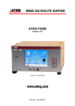
1
QUICK START MANUAL ATEQ F5200 Version 1.01 (Photo no contractual) Reference : MR-F5200B-U REVISIONS OF THE ATEQ F5200 USER MANUAL Due to continuing improvements, the information contained in this user manual, the features and design of this device are subject to be changed without prior notice. Reference Date Week/Year Chapters up dating First edition MR-F5200A-U 46/2010 ----- Second edition MR-F5200B-U 05/2012 Edition/Revision Up-dating the connectors "Installation" chapter. in the ATEQ, THE ASSURANCE OF A COMPETENT AFTER SALES SERVICE THE ATEQ AFTER SALES SERVICE IS : • a team of qualified technicians, • a permanent telephone assistance, • agencies close to you for faster reaction, • a stock of spare parts available immediately, • a car fleet for rapid intervention, • a commitment to quality ... THE OVERHAUL ATEQ carries out the overhaul of your instruments at interesting prices. The overhaul corresponds to the maintenance of the instrument (checking, cleaning, replacing of used parts) as part of preventive maintenance. Preventive maintenance is the best way to guarantee reliability and efficiency. It allows the maintenance of a group of instruments in good operational order and prevent eventual break-downs. MAINTENANCE KITS The ATEQ After Sales Service proposes, two kits destined for the preventive maintenance of the pneumatic circuits of instruments. CALIBRATION This may be carried out on site or in our offices. ATEQ is attached to the COFRAC and delivers a certificate following a calibration. TRAINING COURSES In the framework of partnership with our customers, ATEQ offers two types of training in order to optimise the usage and knowledge of our instruments. They are aimed at different levels of technician: • method / control training, • maintenance / upkeep training. A TARGETED TECHNICAL DOCUMENTATION A number of technical documents are at your disposal to allow you to intervene rapidly in the event minor breakdowns: • problem sheets describing and offering solutions to the main pneumatic and electronic problems, • several maintenance manuals. A QUALITY GUARANTEE The instruments are guaranteed for parts and labour in our offices: • 2 years for leak detection equipment, • 1 year for electrical tests to norms instruments, • 1 year for the accessories. Our After Sales Service is capable of rapidly answering all your needs and queries. We strongly recommend to send the instrument back to ATEQ once a year for re-calibration SAV-Uc/0650 PREFACE Dear Customer, You have just purchased an ATEQ instrument, we thank you for the trust you have placed on our brand. This instrument has been designed to ensure a long and unparalleled life expectancy, and we are convinced that it will give you complete satisfaction during many long years of operation. In order to maximise the life expectancy and reliability of your ATEQ instrument, we recommend that you install this instrument on a secured workbench and advise you to consult this manual in order to familiarise yourself with the functions and capabilities of the instrument. Our ATEQ After Sales Service centre can give you recommendations based on your specific operation requirements. ATEQ 0650/PREFd-U Quick start manual - F5200 Quick start manual TABLE OF CONTENTS TABLE OF CONTENTS .................................................................................................. 1 PREAMBLE .................................................................................................................... 2 1. DEFINITION OF THE ATEQ F5200 ....................................................................................................2 2. MEASUREMENT CHARACTERISTICS..............................................................................................2 3. THE MAIN TYPES OF MEASUREMENT............................................................................................3 4. THE THREE TYPES OF TEST ............................................................................................................3 5. MEASUREMENT CYCLE ....................................................................................................................3 INSTALLATION .............................................................................................................. 4 1. APPEARANCE OF THE ATEQ F5200................................................................................................4 2. ELECTRICS CONNECTORS ..............................................................................................................4 3. PNEUMATICS CONNECTORS ...........................................................................................................7 4. PNEUMATIC SUPPLY.........................................................................................................................7 USER INTERFACES....................................................................................................... 8 1. LCD DISPLAY AND NAVIGATION.....................................................................................................8 2. CYCLE KEYS ......................................................................................................................................8 3. QUICK CONNECTORS .......................................................................................................................8 STARTING UP AND ADJUSTMENTS............................................................................ 9 1. MAIN MENU.........................................................................................................................................9 2. TEST MENU.........................................................................................................................................9 3. TEST TYPE ........................................................................................................................................10 4. PROGRAMS MANAGEMENT ...........................................................................................................10 5. PARAMETERS ..................................................................................................................................11 6. START AND STOP A MEASUREMENT CYCLE..............................................................................12 7. PASSWORD ......................................................................................................................................12 CONFIGURATION MENU............................................................................................. 13 1. EXTENDED MENUS..........................................................................................................................13 2. SPECIAL CYCLES ............................................................................................................................14 3. OTHERS MENUS ..............................................................................................................................14 ACCESSORIES AND CHARACTERISTICS................................................................. 15 1. ACCESSORIES FITTED WITH THE DEVICE...................................................................................15 2. ACCESSORIES IN OPTION..............................................................................................................15 3. TECHNICAL CHARACTERISTIC OF THE F5200 ............................................................................15 ERRORS AND FAULTS ............................................................................................... 16 1. ERROR MESSAGES .........................................................................................................................16 2. IN CASE OF OPERATION DOUBT ..................................................................................................16 INDEX ........................................................................................................................... 17 Due to continuing improvements, the information contained in this user manual, the features and design of this device are subject to be changed without prior notice. MR-F5200B-U Quick start manual ATEQ F5200 Page 1/17 Quick start manual - F5200 PREAMBLE 1. DEFINITION OF THE ATEQ F5200 TEST PART The ATEQ F5200 is a compact air/air leak detector used to test the air-tightness of parts. The method used is based on the measurement of a small variation or drop in differential pressure between the test and reference parts, when both are filled to an identical pressure. DIFFERENTIAL SENSOR REFERENCE PART TEST PRESSURE PIEZO SENSOR 2. MEASUREMENT CHARACTERISTICS 2.1. PRESSURE DROP MEASUREMENT RANGE ACCURACY RESOLUTION Maximum 0 – 50 Pa +/- (2,5% of the pressure + 1 Pa) 0,01 Pa 0 – 500 Pa +/- (2,5% of the pressure + 1 Pa) 0,1 Pa 0 – 5000 Pa +/- (2,5% of the pressure + 10 Pa) 1 Pa 2.2. TEST PRESSURE MEASUREMENT RANGE ACCURACY RESOLUTION Maximum F.S. = 75 mbar* +/- (1,5% of the pressure+ 0,2 hPa) 0,1 % F.S. F.S. < 0,3 bar +/- (1,5% of the pressure + 1 hPa) 0,1 % F.S. 0,3 ≤ F.S. ≤ 1 bar +/- (1,5% of the pressure + 3 hPa) 0,1 % F.S. 1 < F.S. ≤ 5 bar +/- (1,5% of the pressure + 7.5 hPa) 0,1 % F.S. 5 < F.S. ≤ 10 bar +/- (1,5% of the pressure + 15 hPa) 0,1 % F.S. 10 < F.S. ≤ 20 bar * Specific (relative) +/- (1,5% of the pressure + 30 hPa) 0,1 % F.S. F.S. = Full scale. MR-F5200B-U Quick start manual ATEQ F5200 Page 2/17 Quick start manual - F5200 3. THE MAIN TYPES OF MEASUREMENT Direct measurement, indirect measurement and sealed component measurement. These three methods apply to measurements taken both under pressure and in vacuum conditions. The configuration is determined by the application and must be carried out prior to the use of the instrument. 4. THE THREE TYPES OF TEST Test with reference: measurement of a pressure variation between a test part and a reference part. Test without reference: measurement of a variation in pressure between a test part and a sealing connector on the reference side. Test with central zero: test of two parts at the same time. One part is connected to the test side and the other to the reference side. TEST PART DIFFERENTIAL SENSOR TEST PART DIFFERENTIAL SENSOR REFERENCE PART CAP TEST PART DIFFERENTIAL SENSOR TEST PART 5. MEASUREMENT CYCLE WAIT FILL STABILIZATION TEST DUMP The measurement cycle consists of 5 phases: Start 1 2 3 4 5 Coupling time Fill time Stabilization time Test time Dump time MR-F5200B-U Cycle end Quick start manual ATEQ F5200 Page 3/17 Quick start manual - F5200 INSTALLATION See the manuals CDROM for further information. 1. APPEARANCE OF THE ATEQ F5200 2. ELECTRICS CONNECTORS 2.1. ON/OFF SWITCH The ATEQ F5200 is running under a voltage between 100 and 240 V AC. I : ON / O : OFF. 2.2. USB CONNECTOR (FRONT FACE) Allows the connection of various elements USB compatible (mouse, keyboard, memory etc.). 2.3. J9 ETHERNET CONNECTOR Ethernet connector for connecting the device into an Ethernet network (TCP / IP protocol). MR-F5200B-U Quick start manual ATEQ F5200 Page 4/17 Quick start manual - F5200 2.4. J1 CONNECTOR OUTPUT CODES / ANALOGUES 1 2 3 4 5 6 7 8 9 10 11 12 13 14 15 16 PIN 1 PIN 2 PIN 3 PIN 4 PIN 5 PIN 6 PIN 7 PIN 8 PIN 9 PIN 10 PIN 11 PIN 12 PIN 13 PIN 14 PIN 15 PIN 16 COMMON (outputs 1, 2, 3) + 24 V DC Output n°1, open collector Output n°2, open collector Output n°3, open collector COMMON (outputs 4, 5, 6) + 24 V DC Output n°4, open collector Output n°5, open collector Output n°6, open collector 12V Sensor power supply 0V Sensor power supply SENSOR n°1 input SENSOR n°2 input Analogue outputs n°1 COMMON (analogue output 1) Analogue output n°2 COMMON (analogue output 2) Output codes / Analog outputs / temperature sensor. OUTPUT CODES 24V DC 100mA Max Outputs Charge / Load 24 V DC 1 2 0,1 A max 3 4 5 6 TEMP° SENSORS Obligatory diode for an inductive load. 7 8 ANALOGUE OUTPUTS 2.5. J3 CONNECTOR I/O ALL OR NOTHING 1 2 3 4 5 6 7 8 9 10 11 12 13 14 15 16 Inputs / All or nothing outputs. Pin 1 2 3 4 5 6 7 8 9 10 11 12 13 14 15 16 Standard mode Input 1 Reset Common (+ 24 V) Input 2 START Common (+ 24 V) Input 3 Program selection Input 4 Program selection Input 5 Program selection Input 6 Program selection Input 7 Program selection Floating common output Output 1 Pass part Output 2 Test error Output 3 Reference error Output 4 Alarm Output 5 End of cycle 0V Compact mode Input 1 Reset Common (+ 24 V) Input 2 START Common (+ 24 V) Input 3 Program selection Input 4 Program selection Input 5 Program selection Input 6 Program selection Input 7 Program selection Floating common output Output 1Pass part cycle 1 Output 2 Fail part cycle 1 + alarm Output 3 Pass part cycle 2 Output 2 Fail part cycle 2 + alarm Output 5 End of cycle 0V INPUTS (Activating by 24 V DC) Common + 24 V = 0,3 A maxi DRY CONTACT OUTPUTS 60V AC / DC Max 200mA Max The compact mode is a software function which is activated in the CONFIGURATION / CHANGE I/O / OUTPUT menu. 2.5.1. J3 Connector program selection The various test programs can be selected individually depending on the inputs combination of this connector. MR-F5200B-U Quick start manual ATEQ F5200 Page 5/17 Quick start manual - F5200 2.5.2. J3 Connector programmable input Input 7 of this connector can be configured to start the desired function. The functions which can be programmed and available on this input are all the specials cycle: 2.6. J5 CONNECTOR REMOTE CONTROL (OPTION) 1 2 4 3 Used for connection of an intelligent remote control (M12 female connector). 2.7. J6 CONNECTOR DEVICENET INPUT (OPTION) 2 1 Reserved for ATEQ network 5 Used for communication with other ATEQ instruments (M12 male connector). 4 3 2.8. J7 CONNECTOR DEVICENET OUPUT (OPTION) 1 2 Reserved for ATEQ network 3 Used for communication with other ATEQ instruments (M12 female connector). 5 4 2.9. J8 CONNECTOR RS232 OR PROFIBUS OR EXTERNAL SCREEN 5 1 9 Enables the connection of a printer, bar code reader, PC and memory module. 6 PIN 1 PIN 2 PIN 3 MR-F5200B-U Not used RXD data input TXD data output PIN 4 PIN 5 PIN 6 Not used Earth/Ground Not used PIN 7 PIN 8 PIN 9 RTS request to send CTS clear to send Not used Quick start manual ATEQ F5200 Page 6/17 Quick start manual - F5200 3. PNEUMATICS CONNECTORS The automatics connectors or installed on the rear side. 3.1. AUTOMATIC CONNECTOR A AND B (OPTION) To drive pneumatics caps. 3.2. PNEUMATICS TEST OUTPUTS These outputs enable parts to be connected (test, reference). The pressurization output is used for the addition of ATEQ accessories (Y valve). Inputs / Outputs on the rear side of the F5200: Test output T Pressurization output Reference output R 4. PNEUMATIC SUPPLY Air supply is via the filter located on the rear panel of the instrument. The air must be clean and dry. The supply pressure must always be between 4 and 8 bar (400 kPa and 800 kPa). MR-F5200B-U Quick start manual ATEQ F5200 Page 7/17 Quick start manual - F5200 USER INTERFACES See the manuals CDROM for further information. 1. LCD DISPLAY AND NAVIGATION Used to display measurements adjustable parameters. and This screen is a touch screen, to access to the different menus, make a slight pressure on the screen with your finger. Do not use objects, failing to destroy irreparably. Different screens are available to display the results. To scroll the windows, drag with your finger from the left to the right or vice versa. Note: to return directly to the main menu, press and hold the Arrow key. 2. CYCLE KEYS KEYS FUNCTION START key Start a measurement cycle KEYS FUNCTION RESET Key Current measurement cycle stop 3. QUICK CONNECTORS One quick connector may be mounted on the front panel of the instrument. This connector is to check the the calibration. It's used to check the test circuit and enables, by use of a calibrated leak, calculation of the equivalent pressure drop. As this connector is part of the measurement circuit, all its connections must be air tight. MR-F5200B-U Quick start manual ATEQ F5200 Page 8/17 Quick start manual - F5200 STARTING UP AND ADJUSTMENTS 1. MAIN MENU The main menu allows accessing to the different managing menu of the device. Configuration menu access Special cycles menu access Service menu access Save results, parameters or configuration menu Measurement head management menu access Back to previous menu (to return Password configuration directly to the main menu, press and hold the Arrow key) This menu is available by pressing the "Settings" button. 2. TEST MENU The test menu (or window) is the window displayed during a measurement cycle. Device name 8 last results no test Pass part Fail part Alarm Current head name Test widow display. Background color is corresponding with the test result. No test Pass part Fail part Test main parameters displaying Alarm Différents windows are available, see "Display types". Cycle progress bar graph Menus access Test program creation, run program number or parameters adjust: see the manuals CDROM for further information. MR-F5200B-U Quick start manual ATEQ F5200 Page 9/17 Quick start manual - F5200 3. TEST TYPE Test type selection: four tests types are available: ¾ Leak test (LEAK), ¾ Pressure (BLOCKAGE), ¾ Desensitized test (DESENTIZED), ¾ Operator test (OPERATOR). 4. PROGRAMS MANAGEMENT 4.1. LEAK TEST PROGRAM CREATION In the test menu, press the PARAM key. Select the program number to create. Then select the LEAK test type. The parameters menu is displayed, access at each parameter by pressing the corresponding key and by using the numerical keyboard, enter the values and validated by ENTER. Press the "RETURN" key to back to the test menu. 4.2. CURRENT PROGRAM SELECTION From the test menu, press the PROG key. The programs list is displayed; the current program appears in yellow key. Select the new current program by pressing the corresponding key, the color changes and becomes yellow. Press the "RETURN" key to back to the test menu. MR-F5200B-U Quick start manual ATEQ F5200 Page 10/17 Quick start manual - F5200 5. PARAMETERS Main parameters to configure: see the manuals CDROM for further information. Fill time: Time to fill the part to the test pressure. Stabilization time: Time to equalize the pressure between the TEST and REFERENCE components. Test time: Leak measurement time, it depends of the reject level value and the work mode programmed. Dump time: Time to back the part to the atmospheric pressure. Dump time by default is zero. Pressure unit: Pressure unit (bar, mbar, PSI, Pa, kPa, MPa). Maximum fill: Maximum level of the fill pressure. Minimum fill: Minimum level of the fill pressure. Test pressure that the device will automatically regulate. Fill instruction: Remind: the input pressure must be at least greater than 100 kPa (1 bar) of the test pressure. Reject unit : Leak unit displayed. If a flow unit is selected, two parameters are added. Test reject: Level for the test part is fail. Reference reject: Level for the reference part is fail (possible problem on this part). Note: when the reference reject value is 0, the device takes into account the absolute value of the symmetrical test reject. Functions : Extended parameters access menu, that must be activated in the CONFIGURATION then EXTENDED MENUS menu. Note: if no extended parameter has been activated from these menus, the FUNCTION menu is empty. Edition, duplication, deletion or copy of a test program, program number to start: see the manuals CDROM for further information. MR-F5200B-U Quick start manual ATEQ F5200 Page 11/17 Quick start manual - F5200 6. START AND STOP A MEASUREMENT CYCLE Press the START key to launch the measurement cycle. Press the RESET key to stop the current measurement. The "READY" message indicates that the device is waiting for a new test cycle. 7. PASSWORD The password gives or locks access to the device. The default identifier is admin; and its password is admin. The administrator can select different rights following the user. See the "User rights" menu. We invite the administrator to create all the different accounts for each user with the corresponding rights. The "Unsecure time" parameter is the time while the access is available for the selected user, when this time is up, the locking will be on and the user must type its password again to enter parameters. MR-F5200B-U Quick start manual ATEQ F5200 Page 12/17 Quick start manual - F5200 CONFIGURATION MENU See the manuals CDROM for further information. 1. EXTENDED MENUS The extended menu gives access to additional functions. If these functions are activated in the extended menus, they will be found in the FUNCTION menu when the program ist created. If no additional function is activated, the FUNCTION menu is empty. 1.1. ACTIVATION AND ADJUSTEMENT OF THE ADDITIONAL FUNCTIONS Activate the functions in the test parameters "Functions" menu of each program. 1.2. ADDITIONAL FUNCTION LIST ¾ ¾ ¾ ¾ ¾ ¾ ¾ ¾ ¾ ¾ ¾ ¾ ¾ ¾ ¾ ¾ ¾ ¾ ¾ ¾ ¾ ¾ Name Program sequence Units Filter Automatic Connector Calibration check by volume Transient Attenuation (ATR) Pre Fill Type Fill Type Permanent Blowing Valves Codes Auxiliaries Outputs 24 V DC End Of Cycle Mini-Valve Rework Limit Sealed Components Peak Hold Reference Volume Volume Compute Stamp Function Temperature 1 Correction Indirect or recovery measure MR-F5200B-U ¾ ¾ ¾ ¾ ¾ ¾ ¾ ¾ ¾ ¾ ¾ ¾ ¾ ¾ ¾ ¾ ¾ ¾ ¾ ¾ ¾ Sign Automatic Save Electronic Regulator Regulator Control Piezo Auto zero Hour RS232 RS485 Modbus Security Backlight External dump Option I/O Configuration Remote control (RC5) Auto parameter N tests Flow Level No Negative Absolute Display Mode Countdown Quick start manual ATEQ F5200 Page 13/17 Quick start manual - F5200 2. SPECIAL CYCLES To start a special cycle, select it in the "Special cycles" menu, then pres the To stop it, press the key. key or for some cycles the end is automatic. See the manuals CDROM for further information. 2.1. STANDARD SPECIAL CYCLES Following the extended menus validations or following the device options, some des special cycles can appear: None: no special cycle selected. Infinite fill: to pressurize the part with a infinite fill time. Piezo auto zero: to run an auto zero cycle on the piezo sensor and on the electronic pressure regulator. Sealed component learning pass and fail part: this is pressure parameters learning cycles for the sealed component mode. The pass part learning cycle is obligatory. Calibration check: cycle to check the calibration by volume with a pass part. Learning / Check: these cycles allow running a learn or a check cycle (or both) in Pascal or Pascal/sec calibrate mode with a master leak. ATR Learning: cycle to enter ATR parameters; this is to run at each switching on of the device or after a long time without measurement. Volume calculation: cycle to calculate the volume of the test circuit. 2.2. SERVICE SPECIAL CYCLES These special cycles are used to perform operations pressure settings and services on the pressure sensors and the valves. Calibration of pressure sensor 1 on regulator 1 / Calibration of pressure sensor 1 on regulator / Calibration pressure sensor 2 / Differential sensor calibration / Sensor status / Valve Auto-test: 3. OTHERS MENUS Parameters service: to save, recover or delete the test cycles parameters. Result menu: this is to manage the results, display, reset or print. Language menu: to choose the language displayed on the screen. Stand by menu: to turn off the device without unplug it. Stand by can be immediate or scheduled with run and stop hours. MR-F5200B-U Quick start manual ATEQ F5200 Page 14/17 Quick start manual - F5200 ACCESSORIES AND CHARACTERISTICS See the manuals CDROM for further information. 1. ACCESSORIES FITTED WITH THE DEVICE Power supply: The power supply cable of the F5200 allows its connection to the mains supply network (from 100 to 240V AC). 2. ACCESSORIES IN OPTION Master leaks: the master leaks are used to check the device calibration. Micrometer valve and Leak Calibrator (CDF). Automatic connectors with expandable seals Filtration kit. Singles remote controls. 3. TECHNICAL CHARACTERISTIC OF THE F5200 Case dimensions H x L x D (mm): 140 x 250 x 250 Overall dimensions (mm): 140 x 250 x 320 Electric power supply: Pneumatics connections: Weight (kg): Format : 100 à 240 V AC / 2 A 3/5, 4/6 or 6/8 about 6 ½ 19 inches Running temperature: +10°C to +45°C Storage temperature: 0°C to +60 °C MR-F5200B-U Quick start manual ATEQ F5200 Page 15/17 Quick start manual - F5200 ERRORS AND FAULTS See the manuals CDROM for further information. 1. ERROR MESSAGES The ATEQ F5200 can display error messages if there are operational problems. Reference fault / Test fault / Pressure in excess of the full scale / Error on the differential sensor / Pressure in excess of the max. threshold / Pressure below the min. threshold / ATR fault / fault or drift CAL / Valve commutation fault / PROG Error / Inappropriate size for the selected unit of pressure / Sealed component learning error / Sealed component error / Sealed components large leak error / Auto-test fault / 2. IN CASE OF OPERATION DOUBT If a test machine begins to detect too many fail parts (more than three consecutively), it is advisable to carry out a check on the whole unit. The quality of the manufacture and operation of the leak detector should be the last things considered. There is a possibility that the seals may be cut by shavings or worn by repetitive squashing. This can be prevented by regular servicing and replacement of the seals. If all the other checks do not resolve the problem, the instrument’s circuit may be checked. ATEQ does not accept any liability in regard to calibrations and settings to its instruments which are not carried out by its own personnel. MR-F5200B-U Quick start manual ATEQ F5200 Page 16/17 Quick start manual - F5200 INDEX A Accessories ........................................15 Additional functions ............................13 Analogues outputs................................6 Automatics connectors .........................7 C Characteristics....................................15 Current program .................................10 Cycle keys ............................................8 D Definition...............................................2 DeviceNet .............................................6 Display..................................................8 Dump time ..........................................11 E E/S........................................................5 Electrics connectors .............................4 Error Messages ..................................16 Ethernet ................................................4 Extended menu ..................................13 External screen.....................................6 F Fail operation......................................16 Fill instruction......................................11 Fill time ...............................................11 Functions ............................................11 I Installation ............................................4 L Language............................................14 M Main menu............................................9 Main types of measurements................3 Master leaks .......................................15 Maximum fill........................................11 Measurement cycle ..............................3 Measurements characteristics ..............2 Minimum fill.........................................11 N Navigation.............................................8 O Operation fault ....................................16 P Password............................................12 MR-F5200B-U Pneumatic supply .................................7 Pneumatics connectors ........................7 Pneumatics outputs ..............................7 Power supply ......................................15 Pressure unit.......................................11 Printer ...................................................6 Profibus ................................................6 Program creation ................................10 Program Selection ................................6 Programmable input .............................5 Programs edition.................................12 Q Quick connector....................................8 R Reference reject .................................11 Reject unit...........................................11 Remote control .....................................6 Results display....................................14 Results menu......................................14 Results reset.......................................14 RJ45 .....................................................4 RS232...................................................6 RS485...................................................6 S Service menu......................................14 Service special cycles.........................14 Special cycles .....................................14 Stabilization time.................................11 Start cycle...........................................12 Starting up ..........................................10 Stop cycle ...........................................12 T Test menu.............................................9 Test parameters..................................11 Test Reject .........................................11 Test time.............................................11 Test types ...........................................10 Type of test ...........................................3 U USB ......................................................4 User interfaces......................................8 Quick start manual ATEQ F5200 Page 17/17 This document is the exclusive property of ATEQ. It may not be communicated, reproduced or used without prior consent.