1
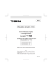
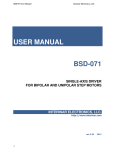
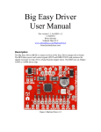
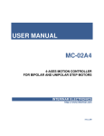
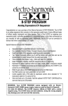
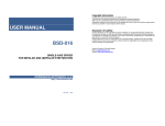
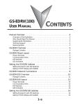
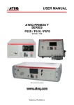
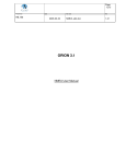
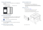
Interinar Electronics
BSD-02 Step Motor Driver
Interinar Electronics
Table 1:
Functional description of BSD-02 Module
Pin #
The BSD-02 module is a complete single-axis microstepping driver suitable for
driving bipolar and unipolar step motors from 50mA to 2.5A and up to 30V.
Driver can operate in one of the 4 stepping modes: Full-, Half-, Quarter- or
Eighth- Step without requiring any phase-sequence tables, high frequency control lines or
complex interfaces to program. Ideal for applications where a complex microcontroller is
unavailable or over-burdened.
Figure 1 Step Motor Driver BSD-02
Features
•
•
•
•
•
•
•
•
•
•
•
•
+/- 2.5A, 30V Output Rating
Eight external Schottky diodes on board
Crossover-Current Circuit Protection
Under-Voltage Lockout Protection
Thermal Shutdown Protection
Automatic Current-Decay Mode
Enable and Sleep Inputs
Built-in Translator
Translator Home State Output
Reduced audible motor noise
Increased step accuracy
Low Quiescent Current (10mA MAX)
www.interinar.com
-1-
BSD-02 Step Motor Driver
Rev.1.3
2-pin Terminal Block J1
Pin Description
1
GND - power ground.
2
+VB - motor supply voltage. Min 8.0V , Max 30V.
Table 2:
10-pin Header J2 (see Figure 2)
Pin #
Pin Description
1
ENABLE - input, active-low. When logic-low all outputs are enabled. When logic-high all
outputs are disabled but Step and Direction signals are still processed in translator. Board has
built in pull-up resistor so if this input is left disconnected the driver will be disabled. This
input is also available on pin 1 of J4.
2
+5V DC - output. Up to 100mA can be drained from this pin to supply power to the external
logic. May be left disconnected if not used.
3
SLEEP – input, active-low. When logic-low all outputs and most of the internal circuitry are
disabled. When logic-high, normal operation resumed and translator set to home state. Board
has built in pull-up resistor assuring normal operation if this input is left disconnected. This
input may be left disconnected when not used.
4
RESET - input, active-low. When logic-low all outputs are off and translator is set to
predefined home state. STEP input is ignored until RESET goes high. Board has built in pullup resistor. This input may be left disconnected when not used.
5
DIRECTION - input. Determines the direction of the rotation of the motor. Depends on how
motor was connected if low was Counter Clockwise then high will be Clockwise and viceversa. Board has built in pull-up resistor. Also available on pin 3 of J4.
6
STEP - input. A low-to-high transition advances the motor one increment. The size of the
increment is determined by MS1 and MS2 (see Table65 and Table 7). Minimum Step Pulse
Width is 1.0us. Minimum Step Low Time is 1.0us. Board has built in pull-up resistor. Also
available on pin 2 of J4.
7
MS2 - input. Together with MS1 determines the size of the increment of the rotation (see
Table6 and Table 7). Board has built in pull-up resistor and jumper JP6 for convenience.
Shipped with JP6 OFF (default).
8
MS1 - input. Together with MS2 determines the size of the increment of the rotation (see
Table6 and Table 7). Board has built in pull-up resistor and jumper JP5 for convenience.
Shipped with JP5 OFF (default).
9
HOME- output. Logic indicator of the initial state of the translator. At power up the translator
is reset to the home state (see Table10 for home state conditions).
10
GND - signal ground.
www.interinar.com
-2-
Rev.1.3
Interinar Electronics
BSD-02 Step Motor Driver
Interinar Electronics
BSD-02 Step Motor Driver
Setting the Max Current Limit.
To guarantee proper operation of the motor it is important to adjust Max Current Limit by
adjusting VREF to appropriate level. Calculation of VREF for Half-, Quarter- and EighthStep Mode is based on the following formula:
VREF [V]= 1.6 * Imax [A]
Figure 2.
Table 3:
Pin #
for example: if motor is rated 1.68A then VREF should be approx. 2.69V
(VREF = 1.6 * 1.68A = 2.69V).
Use Voltmeter connected as per Table 5 and Figure 3.
10-Pin Header J2
4-pin Terminal Block J3
Table 5:
Pin Description
1
O1B - output. Phase 1 output B.
2
O1A - output. Phase 1 output A.
3
O2A - output. Phase 2 output A.
4
O2B - output. Phase 2 output B.
Max current adjustment
Voltmeter
Adjust
Between TP1 and GND
R15
DO NOT CONNECT OR DISCONNECT MOTOR WIRES WHILE
DRIVER IS POWERED OR DRIVER WILL BE PERMANENTLY
DAMAGED!
+
V
________________________________________________________________________
-
Table 4:
Pin #
4-pin Terminal Block J4
Pin Description
Figure 3 Adjustment of Voltage Reference Vref
1
ENABLE - input, active-low. When logic-low all outputs are enabled. When logic-high all
outputs are disabled but Step and Direction signals are still processed in translator. Board
has built in pull-up resistor so if this input is left disconnected the driver will be disabled.
This input is also available on pin 1 of J2.
2
STEP - input. A low-to-high transition advances the motor one increment. The size of the
increment is determined by MS1 and MS2 (see Table5 and Table 6). Minimum Step Pulse
Width is 1.0us. Minimum Step Low Time is 1.0us. Board has built in pull-up resistor.
Available also on pin 6 of J4.
3
DIRECTION - input. Determines the direction of the rotation of the motor. Depends on
how motor was connected if low was Counter Clockwise then high will be Clockwise and
vice-versa. Board has built in pull-up resistor. Available also on pin 5 of J4.
4
GND - signal ground.
www.interinar.com
-3-
Rev.1.3
DO NOT ADJUST Vref ABOVE 4.0V IF OPERATING IN HALF-, QUARTER- OR
EIGHTH-STEP MODES.
For FULL-STEP mode, VREF can be applied up to the maximum of +5V, because the
peak current in FULL-STEP mode reaches only 70.7% of the maximum value.
To calculate Vref in Full-Step mode use following formula:
VREF [V]= 2.26 * Imax [A]
The max current available in Full-Step mode is +/- 2.2A
DO NOT FORGET TO ADJUST THE CURRENT WHEN SWITCHED BACK TO
HALF-, QUARTER- OR EIGHTH-STEP MODES.
If driver will be operated with step mode changing from Full to Microstep during
operation, then Vref should be calculated using formula for Microstep mode.
www.interinar.com
-4-
Rev.1.3
Interinar Electronics
BSD-02 Step Motor Driver
Table 6:
JP #
Jumpers Description
Jumper
Position
5
OFF
ON
6
OFF
ON
MS1 – input. Microstep resolution.
- see Table 7(default)
- see Table 7
Table 7:
BSD-02 Step Motor Driver
Choosing the Power Supply.
Description
MS2 – input. Microstep resolution.
- see Table 7(default)
- see Table 7
Interinar Electronics
VOLTAGE – The BSD-02 driver works by switching the voltage to the motor terminals
ON and OFF while monitoring phase current to maintain its level. Depending on how fast
the motor should run you will need a power supply with voltage rating at least twice that
of the motor. You may use both regulated and unregulated power supplies. A regulated
power supply can be rated up to max allowed voltage for the BSD-02 which is 30Vdc. If
you choose an unregulated power supply do not exceed 21Vdc as they are rated at full
load current. At lesser loads, like when the driver is disabled, the actual voltage of the
power supply may be up to 1.4 times the rated voltage.
CURRENT – The BSD-02 driver requires no more supply current than the sum of the
two phase currents of the motor. The current needed for logic on the board is marginal
and can be ignored in this calculation. In reality you will need a lot less than that,
depending on the motor, speed, load and voltage. The more the power supply voltage
exceeds the rated motor voltage, the less current you will need from the power supply.
For example: a driver powered from 24V power supply will draw approximately only
half of the current that it would if powered from 12V. For that reason we recommend to
use power supply with at least twice the rated phase current of the motor.
Microstep Resolution
JP 6
JP 5
Resolution
ON
ON
Full Step
ON
OFF
Half Step
OFF
ON
Quarter Step
OFF
OFF
Eighth Step (default)
Controlling Mixed Decay Mode.
The driver is shipped with active Mixed Decay mode. First, the driver operates in fastdecay as the trip point is reached. After this fast-decay portion the driver will switch to
slow-decay for the remainder of the fixed off-time period. Fixed off-time is set at 30usec
during manufacturing process and can’t be adjusted.
www.interinar.com
-5-
Rev.1.3
www.interinar.com
-6-
Rev.1.3
Interinar Electronics
BSD-02 Step Motor Driver
Interinar Electronics
BSD-02 Step Motor Driver
Mounting the BSD-02.
The BSD-02 can be mounted in two ways:
1. Using SnapTrack rail attached to your panel with double-stick foam tape or screws.
Driver boards seats firmly in the rail without screws.
(The Snap-Track is available from www.Interinar.com).
2. Using four holes located in the corners of the circuit board. In this case use plastic
standoffs or spacers at least ¼” high to support the board. To fasten the board use #4
screws.
TOP VIEW
AIR FLOW
FRONT VIEW
AIR FLOW
Figure 5 Air Flow direction.
Figure 4 Dimensions and Mounting Holes.
NEVER use heat sink as a support and never attach any objects to it.
DO NOT REMOVE HEAT SINK FROM THE BOARD as it is assembled with
non-reworkable heat transfer material which needs to be replaced once removed.
Heat sink is electronically connected to Ground but it should not be used as Ground
connection.
The BSD-02 features large heat sink which is sufficient for most applications. Heat
dissipated in IC is transferred through thermal vias and pad directly to the heat sink.
Great amount of the heat is also taken away from IC by using external Schottky diodes
while disabling Synchronous Rectification. During extensive use of the driver at the
maximum current the temperature of the heat sink may easily rise 40°C above ambient.
For that reason it is necessary to use external fan providing forced air flow in direction
parallel to the fins of the heat sink. Significant improvement can be achieved with air
flow rates above 400 LFM (2m/s). Figure 5 shows direction of airflow.
www.interinar.com
-7-
Rev.1.3
Use external fan if operating under following conditions:
- current up to 1.4A - no fan needed
- current 1.4 to 2.0A - fan recommended
- current 2.1 to 2.5A - fan necessary
In some cases when the motor works with extremely low rpm or standstill (idle) for long
time waiting for the next step with outputs enabled (Enable signal low) the temperature of
the driver IC may exceed max Junction Temperature of +150 °C. In this case internal
Thermal Shut Down circuitry will be activated at +165 °C, all outputs will be disabled
and motor will stop working. When Junction Temperature falls back below +150°C
driver will resume normal operation. This thermal protection is intended only to protect
the driver from failure when junction temperature exceeds specified limit and should not
imply that output short circuits are permitted. Do not short outputs. Do not connect any
output to Ground or Power Supply. Do not disconnect or connect motor while driver is
powered.
To keep the temperature down it is recommended to disable outputs (ENABLE= HIGH)
when motor standstill (idle phase).
Working at highest temperature range should be avoided also due to step accuracy. When
Thermal Shut Down temperature is reached motor will stop rotating skipping steps. Since
most step motors are used in open loop your controller will not be able to recognize
missing steps and position accuracy will be affected.
www.interinar.com
-8-
Rev.1.3
Interinar Electronics
BSD-02 Step Motor Driver
Interinar Electronics
BSD-02 Step Motor Driver
The BSD-02 may not be able to drive some motors in series connection. Specifically,
construction of 7.5 degree tin-can motors requires different switching sequence. In such
case center tap connection must be used.
Connecting the Motor.
The BSD-02 driver is based on DMOS technology and despite the fact it features output
protection it will be damaged if not properly connected to the motor.
6-LEAD
UNIPOLAR
STEP MOTOR
NEVER CONNECT OR DISCONNECT THE MOTOR TO THE DRIVER WHILE
THE POWER IS ON.
INSULATE UNUSED MOTOR LEADS SEPARATELY.
DO NOT CONNECT ANY MOTOR LEADS TO GROUND OR POWER SUPPLY.
2B
PH2
2A
PH1
1B
1A
- NO CONNECTION
4-LEAD MOTOR
This kind of motor can be connected only one way. See drawing below. If default
direction of the rotation is opposite to the desired then swapping the wires of just one
phase will cause motor to rotate in opposite direction.
2B
BIPOLAR
STEP MOTOR
1B
PH2
PH1
2A
1A
Figure 7. Unipolar motor – bipolar-serial connection.
2. Unipolar connection – one end of each phase is insulated. The other end and center tap
are connected to the driver. Motor should be run at full rated current. This connection
works better at higher speeds.
6-LEAD
UNIPOLAR
STEP MOTOR
PH2
2B
2A
PH1
1B
1A
- NO CONNECTION
Figure 6 Bipolar motor connection.
6-LEAD MOTOR
Motors with 6 leads can be connected in two different ways:
1. Bipolar-Series connection- center tap is not used. Both ends of each phase are
connected to the driver. In series connection motor should be operated at 70% of the rated
current. Running motor at full rated current will saturate and overheat the motor. The
series connection is preferred method because it produces less heat in the driver and
produces higher torque.
www.interinar.com
-9-
Rev.1.3
Figure 8. Unipolar motor – unipolar connection.
www.interinar.com
- 10 -
Rev.1.3
Interinar Electronics
BSD-02 Step Motor Driver
Interinar Electronics
BSD-02 Step Motor Driver
Table 8 shows difference between both configurations in reference to Unipolar.
Mode
Bipolar-Series
Unipolar
Table 8:
Power
1.0
1.0
Ratings for 6-lead motor.
Current
Voltage
0.7
1.4
1.0
1.0
2B
8-LEAD
UNIPOLAR
STEP MOTOR
Torque
1.4
1.0
2A
1B
1A
8-LEAD MOTOR
This motor can be connected in three ways.
1. Bipolar-Series connection which gives more torque at lower speeds and less torque at
higher speeds. In series connection motor should be operated at only 70% of the rated
current because using twice as large winding of each phase produces rated torque at
lower current. Running motor at full rated current will saturate and overheat the motor.
2B
8-LEAD
UNIPOLAR
STEP MOTOR
Figure 10. Unipolar motor – bipolar-parallel connection.
2A
1B
1A
3. Unipolar connection – only one pair of each phase is used. This connection works
better at higher speeds.
8-LEAD
UNIPOLAR
STEP MOTOR
2B
2A
1B
1A
- NO CONNECTION
Figure 9. Unipolar motor - bipolar-series connection.
2. Bipolar-Parallel connection. Motor should be run at 1.4l rated current. This connection
is not recommended as higher current generates more heat in the driver and motor.
Figure 11. Unipolar motor - unipolar connection.
www.interinar.com
- 11 -
Rev.1.3
www.interinar.com
- 12 -
Rev.1.3
Interinar Electronics
BSD-02 Step Motor Driver
Interinar Electronics
BSD-02 Step Motor Driver
Table 10:
Table 8 shows difference between all three configurations in reference to Unipolar.
Mode
Bipolar-Series
Bipolar-Parallel
Unipolar
Table 9:
Power
1.0
1.0
1.0
Ratings for 8-lead motor.
Current
Voltage
0.7
1.4
1.4
0.7
1.0
1.0
Full
Step
Torque
1.4
1.4
1.0
1
All signal inputs of the BSD-02 are at TTL-level and have internal pull-up resistors of
4.7k connected to +5V . Inputs don’t require any source of power. All inputs are sourcing
type and active LOW in reference to GND. This allows direct connection to any TTL
circuitry as well as mechanical switches and relays. Simply shorting any input to GND
will change its status. Unused inputs may be left not connected and will remain HIGH.
The only control output – HOME is also at TTL-level and indicates initial state of the
translator. It may be used in a program when step mode has to be changed while motor is
running. Home State is the position to which the translator is reset at power up. It is also
the state when the current for both phases in equal to 70.71% regardless of selected step
mode allowing smooth and error-free transition from one step mode to another. Home
State is defined at 45deg step angle and with DIR signal High.
1/4 Step
1
2
1
Connecting Control Signals.
Half
Step
2
3
4
3
5
6
2
4
7
8
5
The Table 10 shows Step Sequencing.
Home State is highlighted.
To understand this table imagine bipolar motor with just 4 Full steps per revolution.
9
10
3
6
11
12
7
13
14
4
8
15
16
www.interinar.com
- 13 -
Rev.1.3
www.interinar.com
1/8
1
2
3
4
5
6
7
8
9
10
11
12
13
14
15
16
17
18
19
20
21
22
23
24
25
26
27
28
29
30
31
32
Step Sequencing
Phase 1
Current
Step
(%Itripmax)
(%)
100.00
98.08
92.39
83.15
70.71
55.56
38.27
19.51
0.00
-19.51
-38.27
-55.56
-70.71
-83.15
-92.39
-98.08
-100.00
-98.08
-92.39
-83.15
-70.71
-55.56
-38.27
-19.51
0.00
19.51
38.27
55.56
70.71
83.15
92.39
98.08
- 14 -
Phase 2
Current
(%Itripmax)
(%)
0.00
19.51
38.27
55.56
70.71
83.15
92.39
98.08
100.00
98.08
92.39
83.15
70.71
55.56
38.27
19.51
0.00
-19.51
-38.27
-55.56
-70.71
-83.15
-92.39
-98.08
-100.00
-98.08
-92.39
-83.15
-70.71
-55.56
-38.27
-19.51
Step
Angle
(º)
0.0
11.3
22.5
33.8
45
56.3
67.5
78.8
90
101.3
112.5
123.8
135.0
146.3
157.5
168.8
180.0
191.3
202.5
213.8
225.0
236.3
247.5
258.8
270.0
281.3
292.5
303.8
315.0
326.3
337.5
348.8
Rev.1.3
Interinar Electronics
Table 11:
Characteristic
Motor Supply Voltage
Motor Output Current
Logic Input Voltage
Logic Input Current
Step Frequency
Step Pulse Width (High Time)
Step Pulse Low Time
Comparator Blank Time
Fixed Off Time
Operating Temperature Range
Heat sink Thermal Resistance
BSD-02 Step Motor Driver
Electrical Characteristics at Ta=+25°C
Test
Limit
Symbol
Condition
Min
Typ
VB
Operating
8.0
Continuous
1/2-, 1/4-, 1/8Step Mode
Peak
I0
Continuous
Full-Step
Mode
Peak
VIN(1)
3.5
VIN(0)
IIN(1)
-20
<1.0
Interinar Electronics
BSD-02 Step Motor Driver
Table 12:
Max
30
±2.5
Feature
Unit
V
A*
±2.5
±2.2
±2.2
1.5
20
A*
A*
A*
V
V
A
IIN(0)
fSTEP
-20
-
<1.0
-
20
500
A
kHz
TH
TL
1.0
1.0
-
-
us
us
tBLANK
tOFF
1.1
24
1.4
30
1.7
36
s
s
-
-20
5.65
+85
°C
°C/W
* Motor Output Current is limited by duty cycle, ambient temperature and heat sinking.
Ratings
Symbol
Description
+VB
8.0 to 30.0 V DC Max. Current based on
used motors.
Output Current
IODC
Continuous: from 50mA to 2.5A per each
output. Output Current Rating will be
limited by duty cycle, ambient temperature
and heat sinking. Do not exceed the
specified current rating or a junction
temperature of 150C.
Step Modes
-
Full Step
Half Step
Quarter Step
Eighth Step
Current Decay Modes
-
Mixed Current-Decay
Automatic Current-Decay Mode Detection
and Selection
Protection
-
Under-Voltage Lockout Protection
Crossover-Current Protection
Thermal Shutdown Circuitry with hysteresis
No special power-up sequencing required
Physical dimensions
inch
2.75” x 2.75” x 0.88" (WxLxH)
Load Supply Voltage
Quick Setup Guide.
•
•
•
•
•
•
•
Connect the motor to the driver.
Connect power supply.
Disable the driver by disconnecting any signal from Enable pin.
Connect Voltmeter between GND and TP1.
Calculate Vref based on the phase current of the motor.
Adjust R15 to achieve desired Vref.
Connect Enable, Step and Direction signals
Help.
For technical support send email to: [email protected]
www.interinar.com
- 15 -
Rev.1.3
www.interinar.com
- 16 -
Rev.1.3