1
B.4 Using the Prototyping Board
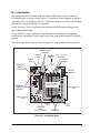
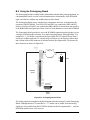
The Prototyping Board is actually both a demonstration board and a prototyping board. As
a demonstration board, it can be used to demonstrate the functionality of the RCM4000
right out of the box without any modifications to either board.
The Prototyping Board comes with the basic components necessary to demonstrate the
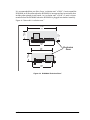
operation of the RCM4000. Two LEDs (DS2 and DS3) are connected to PB2 and PB3,
and two switches (S2 and S3) are connected to PB4 and PB5 to demonstrate the interface
to the Rabbit 4000 microprocessor. Reset switch S1 is the hardware reset for the RCM4000.
GND
+
GND
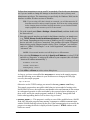
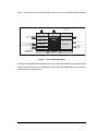
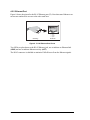
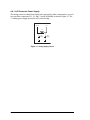
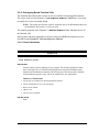
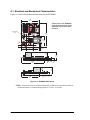
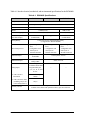
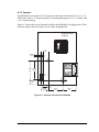
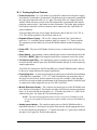
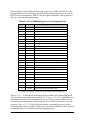
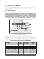
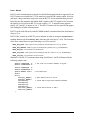
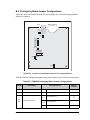
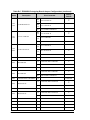
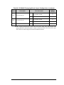
The Prototyping Board provides the user with RCM4000 connection points brought out conveniently to labeled points at header J2 on the Prototyping Board. Although header J2 is
unstuffed, a 2 × 25 header is included in the bag of parts. RS-232 signals (Serial Ports C
and D) are available on header J4. A header strip at J4 allows you to connect a ribbon cable,
and a ribbon cable to DB9 connector is included with the Development Kit. The pinouts for
these locations are shown in Figure B-4.
J1
J4
RS-232
GND
VREF
LN7IN
LN5IN
LN3IN
LN1IN
AGND
GND
/IORD
/RST_IN
PA0
PA2
PA4
PA6
PB0
PB2
PB4
PB6
PC0
PC2
PC4
PC6
PE0
PE2
PE4
PE6
PD0/LN0
PD2/LN2
PD4/LN4
PD6/LN6
CVT
AGND
RxC
TxC
J3
AGND
CVT
LN6IN
LN4IN
LN2IN
LN0IN
RCM4000
Signals
+3.3 V
/RST_OUT
/IOWR
VBAT_EXT
PA1
PA3
PA5
PA7
PB1
PB3
PB5
PB7
PC1
PC3
PC5
PC7
PE1
PE3
PE5
PE7
PD1/LN1
PD3/LN3
PD5/LN5
PD7/LN7
VREF
J2
TxD
RxD
Analog
Inputs
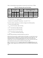
Figure B-4. Prototyping Board Pinout
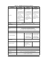
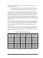
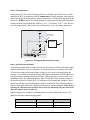
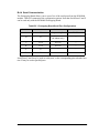
The analog signals are brought out to labeled points at header location J3 on the Prototyping
Board. Although header J3 is unstuffed, a 2 × 7 header can be added. Note that analog
signals are not available from the RCM4010 included in the Development Kit — only the
RCM4000 model has an A/D converter.
User’s Manual
103