1
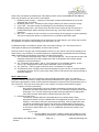
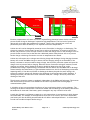
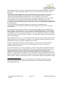
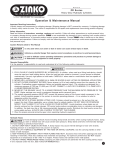
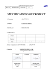
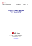
Smart Li Ion Battery User Notes What is a Smart Li Ion Battery? Smart batteries are highly sophisticated lithium Ion battery packs designed for use in a variety of applications in which light weight and high energy storage are required. They use the System Management Bus (SMBus) to communicate with the host device and with the charger. The electronic circuit within the battery has a microprocessor to carry out fuel gauging computations and memory to store key data relating specifically to the lithium ion cells and their associated fuel gauging algorithms. Charging Smart batteries use smart SMBus chargers of level II or higher. The battery will issue commands over the SMBus to the charger in order to control the charge rate and voltage. Upon receipt of the specific charging instructions from the battery, the charger will then configure itself to deliver the appropriate charge. In this way the Smart Battery / Smart Charger system is chemistry & voltage independent. Do not attempt to charge smart batteries with a non-SMBus charger. Discharging The runtime of your smart battery will be reduced if it is operated below room temperature. Runtime is not increased by increasing the temperature, but it will reduce the overall life of your battery. The runtime of your smart battery will be reduced if it is discharged at high currents. (Please refer to the specification document for the maximum continuous discharge current for your battery) Above the maximum discharge current, the safety circuitry will operate (see “Safety” below.) Runtime is not increased by operation at very low currents. The electronic fuel gauge and protection circuitry in your smart battery are designed to use minimal power, thus leaving the maximum energy available for use by the host device. Storage Optimum storage is achieved at room temperature. Elevated temperatures will reduce storage life. Smart Li Ion batteries are shipped with 30 - 50% remaining capacity to give at least 6 months shelf life at room temperature before the electronics go into shutdown mode. It is recommended that the battery is periodically recharged if long storage is required without the electronics going into shutdown mode. Lithium ion cells must not be over-discharged (see “Safety” below). For this reason the electronics in your smart battery have three states of power consumption. 1. Active - the battery is operational and the electronics are actively monitoring and communicating battery status. 2. Sleep - the battery has not been used for a few seconds. 3. Shutdown - the battery is in storage and has self discharged down to a pre-set voltage. At this point the electronics self-disconnect removing their electronic load from the cells. This provides approximately 1 year of room temperature storage before the cells self discharge to the point beyond which they should not be recharged. After a period of shutdown, the battery will undergo a self-test immediately upon being put charge. The electronics will “wake-up” and begin to monitor battery voltage in response to a very low initial charge rate which is delivered by the SMBus charger. If the voltage does not recover then the battery pack has been allowed to discharge beyond the point of safe recovery. The charge will be terminated and the battery pack should be replaced. Smart Battery User Notes 15-0728.docx Page 2 of 7 www.inspiredenergy.com During electronic shutdown, the volatile parts of the memory may have been lost and the SMBus register may need to re-create these during the next few cycles. Until this is completed, fuel gauge accuracy will be reduced. Carrying out a recalibration cycle as soon as possible after shutdown can speed up this process. During electronic shutdown no SMBus data critical to the safe operation of the smart battery is lost. Life End of life for a Li Ion smart battery is defined as the point at which the battery fails to deliver 80% of its original rated capacity. The end of life which is acceptable in your application may differ from this industry definition. The smart battery is designed to provide 300 full charge/discharge cycles at room temperature and under normal discharge rates. Cycle life will be maximized by using the end of discharge instructions issued by the smart battery to the host device over the SMBus. Use of a fixed voltage cutoff by the host device may reduce the cycle life of the product because although the battery may have available capacity remaining it may be at a voltage which is below the device voltage cutoff. If the smart battery is not fully discharged each time, the number of cycles available over life will increase. The Fuel Gauge Your smart battery employs either a 5 segment LCD fuel gauge that is always active unless the battery is in shutdown mode, or a 4-segment LED fuel gauge which is activated by a pushbutton. For LCD fuel gauges: Between 81 and 100% charge, all 5 LCD segments will be filled Between 61 and 80% charge, 4 LCD segments will be filled Between 41 and 60% charge, 3 LCD segments will be filled Between 21 and 40% charge, 2 LCD segments will be filled Between 1 and 20% charge, 1 LCD segment will be filled The LCD fuel gauge will also flash the most significant segment during charge For LED fuel Gauges: Between 76 & 100% charge all four LED’s will light Between 51 & 75% charge 3 LED’s will light Between 26 & 50% charge 2 LED’s will light Between 10 & 25% charge 1 LED will light Below 10% charge, one LED will flash Below 1% charge, there will be no fuel gauge indication & fuel gauge accuracy in normal use is typically ±1.5%. The smart battery continuously monitors the accuracy of its on-board fuel gauge and broadcasts its accuracy level over the SMBus. This information can be used by the host device to inform the user if there is a need to recalibrate the electronic fuel gauge. The SMBus The smart battery communicates 34 separate pieces of battery status data to the host device and/or charger over the SMBus. How many of these are used and how effectively they are employed depends on the host device design. The smart battery has an on-board meter to measure current and voltage in and out of the battery at a resolution of <1mV and <0.5mA for the on-board fuel gauge. Temperature is monitored to within ±3°C. Smart Battery User Notes 15-0728.docx Page 3 of 7 www.inspiredenergy.com Some of the information provided by the smart battery which can be transmitted over the SMBus & which may be useful to a device user is listed below: 1. Remaining time to empty – a measure of how much runtime remains based on the current discharge rate (in minutes) 2. Remaining time to full – a measure of how long the battery will take to reach full charge 3. Cycle count – how many charge and discharge cycles the battery has undergone 4. Remaining time alarm – this can be set by the host device to give the user a warning at a predetermined point before the device shuts down (eg “you have 5 minutes of runtime remaining) 5. Max error – a measure of how accurately (or inaccurately) the fuel gauge is currently operating. This can be used by the device to notify the user to recalibrate the battery pack. Although this information is broadcasted to the host device and the charger, your device may not have the capability to transmit these messages from the battery to you. A USB-based reader is available by special order from Inspired Energy, LLC. this allows a user to interrogate the battery and immediately view the battery status. The host device or charger may not be designed to listen to or act upon the instructions issued by the smart battery. As a minimum, for optimum operation, Inspired Energy recommends that the following SMBus commands from the battery are used by the device and charger: 1) The “Terminate Discharge Alarm” and/or “Fully Discharged” bit. This will provide the user with maximum runtime and cycle life throughout the life of the product and to ensure proper calibration cycles are achieved. 2) The “Terminate Charge Alarm” and/or “Fully Charged” bit to maximize capacity, ensure correct, full charging and to ensure proper calibration cycles are achieved. 3) The “Max Error” value to signal to the user when a recalibration is required. 4) The Remaining Time To Empty value should be employed to give the user an accurate update on remaining runtime. This is a much more useful value to the end user than the percentage of remaining capacity. Battery Maintenance In certain applications where a lot of battery packs are deployed together there is a need for a program of battery maintenance. Ideally this should be undertaken on a regular, periodic schedule so that battery performance trends can be monitored and batteries removed from the population prior to their end of life. There are three main parts to the creation of a battery maintenance program: 1. Frequency of battery monitoring More data is always better, but more frequent maintenance interrupts the operation schedule & decreases the benefit versus the cost. For a battery program involving daily discharges, a 2 or 3 month monitoring schedule would provide plenty of data points with which to assess performance trends and predict end of life. 2. Definition of end-of-life The industry standard definition described above is not always ideal & many applications benefit from the establishment of an application-specific end of life. For example, if the battery has been conservatively specified, then the application may still deliver acceptable performance even when the available battery capacity has shrunk to 50% of its original capacity. Three commonly-used methods of determining end of life are shown below. Any, all, or a combination may be most suited to your application. Cycle Count. Here the SMBus cycle counter is used to monitor the number of cycles accumulated by the battery & a threshold is established beyond which Smart Battery User Notes 15-0728.docx Page 4 of 7 www.inspiredenergy.com the battery is recommended for replacement. This may be 300 cycles or a higher figure to suit your application. Calendar Life. The SMBus manufacturing date is compared to today’s date to determine the age of the battery. This is slightly less relevant as an end-of-life determinant as Li Ion batteries can operate for many years in benign environments. Often this is used as a backup end of life determinant. (eg “replace after 300 cycles or 10 years”) Full Charge Capacity depletion. This system offers dynamic monitoring which only flags a battery for end of life when its actual performance is approaching the point beyond which it will no longer fully perform its intended function. The SMBus is used to interrogate the battery for its Full Charge Capacity. This value can be compared to the Design Capacity (Also available over the SMBus). A end-of life point can then be determined based on the specific application. For example you may choose to replace any battery in which the FCC has dropped to 70% of the DC. Other methods, such as high rate discharge tests, may be used if the application requires a specific performance parameter to be met, but most maintenance programs use a combination of these three parameters with trigger-points to suit the needs of the specific application. (eg if FCC < 70% DCC, or Cycle Count >350, or calendar life > 5 years) 3. Method of monitoring This is a key benefit of a SMBus battery because the battery data is perfect for this purpose. Inspired Energy offers the ATA004 USB based SMBus reader which may be deployed for this type of use. ATA004 USB to SMBus Reader. This allows the maintenance operator to read & log the data from each battery. Using the “Y” cable (included) the unit can read & log SMBus communications & system parameters in real time during charge & discharge. Each battery carries a unique serial number, so every time the same battery is checked, its data can be compared to its previous monitoring point. Data from the ATA004 can be saved as a spreadsheet for sorting & analysis. Treading the data directly into a spreadsheet via USB enables the maintenance operator to quickly & easily monitor a fleet of battery packs. Any battery that is flagged with a potential problem can then be analyzed in greater detail during a charge & discharge cycle. Safety Lithium Ion cells contain a lot of stored energy. They require protection to ensure that this energy is always delivered in a controlled manner. The smart battery features passive and active electronics with multiple levels of redundancy to ensure that the battery remains safe in all failure modes. The two sketches below illustrate the response of lithium ion cells to varying temperature, current and voltage, and demonstrate how the multiple levels of protection devices function to ensure that the cells remain within the safety containment zone at all times. Smart Battery User Notes 15-0728.docx Page 5 of 7 www.inspiredenergy.com Temperature Temperature Cell Failure Zone Cell Safety Zone Electronic protection Cell Safety containment Zone Thermal Fuse Charge control circuit wi tc h Elec. disconnect Elec. Protection cutoff Device Cutoff Voltage Cell Failure Zone Electronic protection Po lyS Thermal Fuse Voltage Current Excessive temperatures will cause cell failure. Inspired Energy batteries feature devices which will prevent further charge or discharge if exposed to high temperatures. The first level of protection devices will re-set when the temperature is lowered. There is also a thermal fuse, which will permanently shut down the battery if it is exposed to excessive temperatures. Lithium Ion cells can be damaged by excessive current flow either in charging or in discharging. The electronic protection circuit senses current flow in and out of the battery. If excessive currents are sensed, the protection circuit will open a switch in either the charge circuit or the discharge circuit to prevent further current flow in that direction. Additional passive safety devices will act to prevent further charge or discharge if excessive currents or temperatures are sensed. Lithium ion cells require strict voltage control during charge and discharge. During charging the smart battery will control the SMBus charger to ensure that the charging voltage is not exceeded. If the battery continues to receive excessive charge voltage, the electronic protection system will open the charge circuit to prevent further charging. When the source of excessive voltage is removed, normal charging can resume. During discharge the device should be designed to shut off at a safe, predetermined voltage. Inspired Energy recommends that the device uses the SMBus end of discharge alarms issued by the smart battery to gain maximum runtime over the life of the battery pack without impacting safety. If the device continues to discharge the battery beyond the cutoff voltage, the electronic protection system will disconnect the discharge circuit and prevent further discharge. If discharge continues, the electronics enter shutdown mode (See “Storage” above) to prevent over discharge of the cells. The electronic protection system is completely independent of the SMBus and fuel gauge. This ensures that the electronic protection is not disabled in the case of a problem with the fuel gauge or communications system. It is healthy to have concerns about the safe use of any stored-energy device such as a battery. The warnings in the device manufacturer's instruction manual and the warnings on the battery label should be heeded at all times and if the battery pack is damaged in any way it should not be used. A good rule of thumb for all battery systems is to only operate them in environments in which humans are comfortable. For example, if the temperature is too hot or too cold for you to feel comfortable, your battery will also be feeling uncomfortable & will deliver reduced performance - it will be better to wait until conditions improve before using it. Smart Battery User Notes 15-0728.docx Page 6 of 7 www.inspiredenergy.com The high media interest in the Li Ion safety benefits us all because it heightens everyone’s awareness of the need for care when using these products. However, lets put the current situation in some perspective, - More than 1,900 million mobile phones were manufactured last year - each with a single Li ion cell. - More than 200 million laptops were made last year, each with approxmimately 6 Li Ion cells. - More than 350 million tablets were made last year – each containing 1 or 2 Li Ion cells - Add-in the many millions of industrial devices, plus the spares & replacements & we can estimate that the global Li Ion cell industry is producing more than 5 billion individual cells per year. - Lithium Ion batteries typically have a life of 300 cycles with each cycle representing an opportunity for a failure; hence the cells manufactured last year alone will have 1,500,000,000,000 opportunities to fail catastrophically. - Each year that passes increases this opportunity for failure by an increasing amount. It is a testament to the manufacturing quality of the major suppliers that there are so few safetyrelated events. All Lithium Ion battery packs require the use of an electronic protection circuit plus passive safety devices. However, the protection circuit can only protect against EXTERNAL events - if the cell has an internal problem, then the protection circuit is ineffective. This demonstrates the value of choosing good suppliers & the value of good product design. No Li ion cell manufacturer has had zero incidents with their products so we must choose from the best – this means NOT cutting corners & choosing the lowest cost cell supplier. Inspired Energy only uses "tier 1" Li ion cell manufacturers whose cells conform fully to UL1642. Good design principles are used throughout our operation, & our designs also enable the battery pack to be assembled with safety in mind for the assembler & the end user. Customers always want more power in smaller packages. It is the job of us all to ensure that our customers understand that with this power comes responsibility for everyone in the supply, manufacturing & end-use chain. As a device manufacturer, your role is to design your device so that it does not negatively impact the battery in any way & you have a responsibility to inform your customers and end users of the correct way to handle and use your device and its battery. Inspired Energy has full technical support capabilities to ensure that you have the best information available to you in fulfilling your role. This document, the client-page on our website, and our specification documents (Available on the product pages of our website) are all excellent starting points to assist in your design & the compilation of your own user manual - please do not hesitate to contact us for additional design & implementation support. Smart Battery Specifications For a detailed engineering specification, including details of the SMBus communication system, engineering data sheets for all Inspired Energy smart batteries are available to download from www.inspiredenergy.com. Smart Battery User Notes 15-0728.docx Page 7 of 7 www.inspiredenergy.com