1
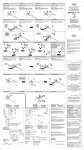
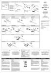
SENSOAIR
Technische und farbliche Änderungen vorbehalten
Air quality sensor for indoor use
Assembly Instructions
Table of contents
Important notice ....................................................................................................2
Function ...............................................................................................................4
Device description .................................................................................................5
Technical data ......................................................................................................6
Installing the wall unit .............................................................................................8
SENSOAIR plus ...................................................................................................10
- Wiring diagrams for ventilation units ....................................................................11
- Wiring diagrams for motor-driven window drives ..................................................12
Device control .....................................................................................................14
SENSOAIR Start-Up .............................................................................................14
SENSOAIR wave Start-Up .....................................................................................16
Product Liability ...................................................................................................19
Important notice
Read the following notice carefully prior to the first commissioning.
Appropriate Use
• Only use the unit for measurement and control in enclosed, dry and dust-free
rooms.
• Maintain a room temperature of 5 °C - 40 °C.
• The unit is not suitable for use as a measuring device or as part of a gas warning
device or similar safety device.
• Do not use solvents near the unit.
• Silicon vapours can have an effect on how the unit works.
• Use this unit only with original accessories from SIEGENIA-AUBI.
• Installation of the unit must always be undertaken by a specialist, in accordance
with the installation and planning documentation from SIEGENIA-AUBI. The
assembly instructions contained in this manual are to be adhered to (page 8, 9).
• Use the unit only in a technically perfect state. Do not make any changes on the
components of the unit.
• Ensure that the air openings remain vacant and are not blocked by other
equipment, furniture or objects.
• In case of defects the unit must be checked by a specialist.
2
Important notice
Read the following notice carefully prior to the first commissioning.
Safety information
Exposed electrical components.
Danger of death by electrocution or fire.
X To avoid injury and material damage it is mandatory to observe the following
instructions:
• Only insert the Europlug of the standard connecting cable into a suitable 230 V AC
socket.
• If the mains connection cable for this device is damaged, it must be replaced by
SIEGENIA-AUBI, their customer service department, or similar qualified personnel
in order to prevent hazards.
• Should work on the 230 V AC mains power supply be necessary in order to connect
the device, it may only be performed by a qualified electrician.
• An all-pole safety isolation is required when the customer lays the power cable.
The fuses may need to be removed.
• Current local regulations (such as VDE 0100 in Germany) must be observed.
Relevant country-specific regulations must be strictly followed for all work on the
voltage supply system or house wiring system.
• Do not connect the device's control line and low voltage connections with the
230 V AC mains power supply. This can destroy all connected devices.
• Should a hard object or fluid get into the interior of the device, stop operation
immediately and disconnect the device from the mains power supply.
3
Function
Breathing clean air is an important requirement for our health and productivity, and
the amount of carbon dioxide in the air is an important factor. A high concentration
of this colourless and odourless gas degrades air quality, and in extreme cases, it can
negatively impact your health.
Both SENSOAIR devices "basic and plus" use two sensors to measure the carbon
dioxide concentration (CO2) concentration and the level of volatile organic
compounds (VOCs) in closed rooms. VOCs are volatile, organic compounds in the
form of gases, such as cigarette smoke, body perspiration, kitchen odours, and the
like.
SENSOAIR wave measures the carbon dioxide concentration (CO2) with only one
sensor.
The measured air quality is indicated using an LED traffic light.
Red
= Poor air quality — Ventilation is required
Yellow = Medium air quality — Ventilation is recommended
Green = The air quality is good
4
LED indicator
Ventilation
2x brief red flashes
Urgently required
1x long red flash
Urgently required
Continuously red
Required
Yellow/red
Required
Continuously yellow
Recommended
Green/yellow
Not required
Continuously green
Not required
Device description
SENSOAIR device types
Design
Typ
Mains connection
Table
unit
Wall
unit
230 V
AC
24 V
DC
basic
9
plus
-
9
9
9
9
9
9
9
9
9
wave
9
Functions
Measure/
display
Device
control
CO2 + VOC
-
CO2 + VOC
by wire
CO2
by radio
Example of device control
SENSOAIR plus
detects poor room air ...
... and sends control signals...
... to a wall-mounted
ventilator, such as the
AEROPAC SN,
which then pumps
fresh air into the
room
Scope of delivery
• SENSOAIR basic
Table-unit design with power cable:
-- 1 Assembly instructions
• SENSOAIR basic, plus, wave
Wall-unit design without power cable:
-- 1 bag of plate screws, 4 mm x 30 mm, with dowels
-- 1 Assembly instructions
5
Technical data
The concentration of CO2 and VOCs in the air is measured in parts per million
(ppm). The CO2 concentration outdoors is approx. 350 ppm. A level of above
approx. 800 ppm negatively impacts our well-being.
If the CO2 content or the VOC concentration exceeds the following values,
SENSOAIR indicates this using the LED traffic light and connected devices are
activated.
The concentration of CO2 in the ambient air depends on the number of people in the
room and the length of time those people have spent in the room as well as the size
of the room volume and the air exchange rate. For example if there are two people
in a room with a total volume of 60 m³ and an air exchange rate of 1, a CO2 content
of 900 ppm would be reached. Without ventilation, the concentration of CO2 would
rise to 1500 ppm after two hours and increase to 2500 ppm after five hours.
CO2 concentration in ppm
LED indicator
CO2
2x brief red flashes
2500
1x long red flash
2000 and
above
Continuously red
1500
Maximum permissible value for
offices and classrooms
Yellow/red
1000
Maximum permissible value for living spaces
Continuously
yellow
800
Air is perceived as being poor
Green/yellow
600
Air quality is becoming worse
Continuously green
350
Clean, fresh air
Impact
Air quality is very poor
VOC concentration in ppm
6
LED indicator
Ammonia
Ethanol
Hydrogen
sulphide
Toluene
Yellow/red
60
20
4
2
Continuously
yellow
30
10
2
1
Green/yellow
15
6
1
0.08
Continuously green
10
3
0.05
0.05
Technical data
SENSOAIR basic
Measurement of CO2 and VOC
SENSOAIR plus
Measurement of CO2 and VOC
SENSOAIR wave
Measurement of CO2
Measuring range of sensors
Approx. 350 - 3000 ppm (CO2 and VOC)
Service life of sensors
Approx. 10 years
Permissible room temperature
5 °C to 40 °C
Supply voltage
230 V AC / 24 V DC (depending on the unit)
Power consumption
1.5 W
Device control (optional)
Air quality values can be adjusted with a DIP switch
Protection class
II, all-insulated
Degree of protection
IP 4X
Casing
Surface-mounted, ASA, RAL 9003 signal white
Dimensions (W x H x D)
154 mm x 98 mm x 39 mm
7
Installing the wall unit
Installation requirements
• Suitable location for installation:
-- Ideally, above an in-wall mounted box
-- Not in the immediate proximity of windows, ventilation equipment and people
or animals
• On a smooth, even wall
• Maintain a temperature of 5 °C - 40 °C during installation
• During installation and before start-up, protect the device against:
-- Dirt (e.g. cover ventilation grilles when wallpapering, etc.)
-- Draught and directly exhaled air
-- Direct sunshine
Installation
Exposed electrical components.
Danger of death by electrocution or fire.
X For customer-installed mains cables, safety isolation of all poles is mandatory.
If necessary the fuses have to be removed.
Installation
c
d
e
f
g
8
Remove the casing cover (in the delivered state, the cover is not clipped on).
Remove the pre-punched drill hole cut-outs and the power cable cut-out
(depending on the unit) using a suitable tool.
Pull the power cable (provided by customer) through the appropriate cable cutout, position the housing bottom half and use as a drilling template.
Drill the holes for wall mounting.
Mount the housing bottom half using two 4 mm x 30 mm clamping screws and
dowels (included).
a. Connect the 230 V AC power cable, or
b. Connect a power cable for 24 V DC.
You can then perform the procedures for connecting and controlling devices
(see page 10 - 14).
Clip the casing cover back on prior to start-up.
Installing the wall unit
d
e
fa.
12 3 4
c
230 V AC
12 3 4
g
fb.
24 V DC
12 3 4
9
SENSOAIR plus
Connecting devices
SENSOAIR plus controls connected devices
(e.g. ventilators and motor-driven window drives)
using 230 V AC or 24 V DC control lines.
The devices are connected to a control board.
Important! Observe the wiring diagrams for
device connections.
Note: If necessary, carefully open the casing
cover using a suitable object (such as a coin or
a screw driver).
230 V AC power supply
Mains circuit board
Control board
Mains circuit board
Control board
12 3 4
12 3 4
230 V AC control lines
24 V DC control lines
24 V DC power supply
10
12 3 4
Basic circuit board
(without mains
circuit board)
230 V AC / 24 V DC
control lines
Control board
Wiring diagrams for ventilation units
SENSOAIR plus - AEROMAT VT / AEROLIFE / AEROVITAL /
AEROPLUS / AEROPAC SN
SENSOAIR plus
Relay 2
Relay 1
Relay 2
Relay 1
Switch distribution box, provided by customer
AEROMAT VT
AEROLIFE
Type RS / RS 2
AEROVITAL
AEROPLUS
AEROPAC SN
SENSOAIR plus - AEROMAT 100 DK / AEROMAT 150
AEROMAT 100 DK
Relay 2
SENSOAIR plus
Relay 1
Relay 2
Relay 1
Switch distribution box, provided by customer
AEROMAT 150
11
Wiring diagrams for motor-driven window drives
SENSOAIR plus - Motorised handle MH10
Power supply VPS1
Relay 2
SENSOAIR plus
Relay 1
Switch distribution box, provided by customer
MH10
SENSOAIR plus - Chain drives
Power supply ACX
Chain drive
12
Relay 2
SENSOAIR plus
Relay 1
Relay 2
Relay 1
Switch distribution box, provided by customer
Device control
All of the devices listed below are activated/deactivated using preset air quality
values (LED indicator).
The presettings are made by means of DIP switches on the basic circuit board.
DIP switch example
Switch 1: OFF
Switch 1: ON
Important! Do not switch on the power supply until all DIP switches
have been configured (this applies to all SENSOAIR device types).
SENSOAIR plus - Ventilation devices
Fan control
with
blower levels
AEROMAT VT
Type RS / RS 2
AEROMAT 100
Type F2
AEROMAT 150
DIP switch position
Fan blower levels for LED indicator
Yellow
Yellow
/red
Red
I
I
II
II
I
II
II
II
I
II
II
II
Off
Off
I
II
I
I
II
II
I
II
II
II
I
II
II
II
Off
Off
I
II
On
On
On
2
3
4
Green
Green/
yellow
OFF
OFF
OFF
OFF
Off
ON
OFF
OFF
OFF
Off
OFF
ON
OFF
OFF
I
ON
ON
OFF
OFF
Off
OFF
OFF
ON
OFF
Off
ON
OFF
ON
OFF
Off
OFF
ON
ON
OFF
I
ON
ON
ON
OFF
Off
OFF
ON
Off
On
1
Fan control: Blower "On" / "Off"
AEROLIFE
OFF
OFF
AEROVITAL
ON
OFF
OFF
ON
Off
Off
On
On
On
AEROPLUS
OFF
ON
OFF
ON
Off
Off
Off
On
On
AEROPAC SN*
ON
ON
OFF
ON
Off
Off
Off
Off
On
AEROMAT 100
Type DK (bag
closing flap
"Open"/
"Close")
OFF
OFF
OFF
ON
Close
Open
Open
Open
Open
ON
OFF
OFF
ON
Close
Close
Open
Open
Open
OFF
ON
OFF
ON
Close
Close
Close
Open
Open
ON
ON
OFF
ON
Close
Close
Close
Close
Open
* Available from the middle of 2009
13
Device control
SENSOAIR plus - Motor-driven window drives
Motor-driven
window
drives
Motorised
handle
MH10
Chain drives
DIP switch position
Window position for LED indicator
1
2
3
4
Green
Green/
yellow
Yelllow
Yellow
/red
Red
OFF
OFF
ON
ON
Close
Open
Open
Open
Open
ON
OFF
ON
ON
Close
Close
Open
Open
Open
OFF
ON
ON
ON
Close
Close
Close
Open
Open
ON
ON
ON
ON
Close
Close
Close
Close
Open
OFF
OFF
OFF
ON
Close
Open
Open
Open
Open
ON
OFF
OFF
ON
Close
Close
Open
Open
Open
OFF
ON
OFF
ON
Close
Close
Close
Open
Open
ON
ON
OFF
ON
Close
Close
Close
Close
Open
Function test for connected units (automatic)
1. Switch on power supply,
2. relay 1 switches on after 30 seconds,
3. relay 2 switches on after 60 seconds,
4. both relays switch off after 90 seconds and the test is complete.
SENSOAIR Start-Up
Before operating the unit for the first time, all SENSOAIR device types must be
calibrated — as described below.
Requirements
• The room must be aired out well before calibrating.
• The room temperature must be between 5 °C and 40 °C.
• There should be no persons or animals in the room.
Calibration
1. Switch on the power supply – the calibration begins.
2. Both sensors are heated up and calibrated to the reference value of 350 ppm
— the LED flashes green (1x long).
3. After calibration is complete (duration = 30 min.), the LED is continuously green.
The device is now ready for operation.
14
SENSOAIR Start-Up
Malfunctions
In case of a malfunction, do not open the device or try to repair it under any
circumstances. To repair malfunctions, please contact your certified specialist or
SIEGENIA-AUBI Service Consulting: Tel. +49 271 3931- 471.
LED indicator
Description
Reason
Solution
1x long green
flash every second
Function is interrupted
(e.g. after a power outage)
The device is
calibrating
Wait for the
calibration
to finish
2x short green
flashes per second
The CO2 sensor
is defective
-
Contact
the service
department
1x short red
flash per second
The VOC sensor
is defective
-
Contact
the service
department
Cleaning
Danger of death
by electrocution or fire.
X To avoid injury and material damage it is mandatory to observe the following
instructions:
• Before cleaning please always disconnect the power supply (never pull on the cable) to isolate the unit from the mains.
• For units with a permanent connection, switch off the all-pole mains supply line.
If necessary the fuses have to be removed.
• Do not use any aggressive substances or solvent detergents for cleaning, as the
unit's surface may be damaged.
• When cleaning the unit, liquid must not penetrate inside the interior part.
15
SENSOAIR wave Start-Up
SENSOAIR wave will be integrated in the Z-Wave wireless network.
Note: The following documentation for connecting the SENSOAIR wave to the
Z-Wave wireless network is exclusively intended for trained specialists.
Inclusion / Exclusion
Press the push-button on the bottom of the unit once to include SENSOAIR wave into a
Z-Wave Net or to exclude SENSOAIR wave from the Z-Wave Net.
Inclusion into an existing Z-Wave Network
The SENSOAIR wave is fully Z-wave compliant and can be operated together with
3rd party Z-wave devices. For inclusion press the button at the Z-wave device which
manages the system administration (refer to the device user manual). Then include
the SENSOAIR wave via the push-button.
Resetting the SENSOAIR wave to the factory setting
Press and hold the button on the bottom of the unit for 5 seconds
A short flashing yellow LED confirms the following actions:
• SENSOAIR was included in or excluded from a Z-Wave Net.
• An association was established
• The device was reset to the factory setting
Supported classes
• COMMAND_CLASS_BASIC
• COMMAND_CLASS_SENSOR_MULTILEVEL_V3
• COMMAND_CLASS_SENSOR_CONFIGURATION
• COMMAND_CLASS_CONFIGURATION
• COMMAND_CLASS_ASSOCIATION
• COMMAND_CLASS_VERSION
• COMMAND_CLASS_MANUFACTURER_SPECIFIC
16
SENSOAIR wave Start-Up
Class functions
BASIC SET
• Basic Set Value = 1, if current CO2 concentration > CO2 trigger level
• Without an association it sends a broadcast, with an association it sends a single cast
BASIC REPORT
• Basic Report Value = CO2 /10 in a range from 35 to 255 which corresponds
to 350 - 2550 ppm
• Basic Report Value = 0 during calibration mode (30 min. after power on)
MULTILEVEL REPORT (Version 3)
•
•
•
•
•
Sensor type = CO2 (0x11)
Precision = 0x00
Scale = ppm (0x00)
Sensor Value 1 (MSB) and Sensor Value 2 (LSB) = CO2 level 350 - 3000 ppm
In Unsolicited Report Mode A/B, the CO2 value is sent without being requested
(see Device Configuration)
SENSOR CONFIGURATION
• CO2-Triggerlevel can be set with SENSOR_TRIGGER_LEVEL_SET
within 500 - 3000 ppm
• Default-Bit: Reset Trigger Level to factory default (1000 ppm)
• Current-Bit: Set Trigger Level to the current CO2-Level
• Sensor Type = 0x11
• Precision = 0; Scale = 0; Size = 2
• Trigger Value 1 = MSB; Trigger Value 2 = LSB
17
SENSOAIR wave Start-Up
DEVICE CONFIGURATION
Use the CONFIGURATION_SET command to configure the device operating mode.
Device Configuration Value 1 (default 0x8d):
7
6 5 4
3
2
1
0
SENSOAIR
LEDs
Broadcast
Multilevel
Report
Basic Set
Unsolicited
Multilevel
Report
Mode B
Unsolicited
Multilevel
Report
Mode A
0 = disabled
1 = enabled
0 = disabled
1 = enabled
0 = disabled
1 = enabled
0 = disabled
1 = enabled
0 = disabled
1 = enabled
Unsolicited Multilevel Report Mode A
SENSOAIR sends an unsolicited multilevel report when the CO2 value
exceeds one of the following threshold values:
600 ppm, 800 ppm, 1000 ppm, 1500 ppm, 2000 ppm, 2500 ppm
Unsolicited Multilevel Report Mode B
SENSOAIR sends the current CO2 value (without being requested) in an interval of
5 - 65000 seconds. The interval (default setting = 30s) is configured as follows:
Device Configuration Value 1 = MSB (default 0x00)
Device Configuration Value 2 = LSB (default 0x1e)
18
Product Liability
Directions of use
Any inappropriate or unconventional use of the product, or failure to operate correctly
will deem the product to be excluded from warranty. Any adjustment or change to
the product or its components without prior authorisation by SIEGENIA-AUBI is strictly
forbidden.
Warranty
A 2 year warranty is given, subject to the correct installation and use of the product,
in accordance with the statutory regulations.
As part of any remedial work we are entitled to replace individual components or
whole units in the installation. Consequential harm caused by a defect is excluded
from the warranty – insofar as legally permissible.
Should any alterations to the product and / or to the individual components be made
that have not been authorised by SIEGENIA-AUBI or have not been described here,
or should the product and / or individual components be un-assembled or dismantled,
the warranty shall be deemed null and void.
Exclusion of liability
The product and its component parts are subject to strict quality control. They will thus
work safely and reliably when used normally.
We rule out our liability for consequential harm caused by a defect and / or for claims
for damages unless we have acted wilfully or with gross negligence or respectively
are responsible for injury to life, body or health. This does not affect any liability under
the product liability law, irrespective of who is to blame.
Also unaffected is the liability for the culpable breach of fundamental contractual obligations; the liability in such cases however is limited to the foreseeable damage typical of the contract. There is no change to the burden of proof to the detriment of the
consumer associated with the above rulings.
Declaration of conformity
According to the EU regulations (2002/96/EG and 2003/108/EG)
and the ElectroG, SIEGENIA-AUBI products are compliant with the WEEE
(Wast Electrical and Electronic Equipment).
Environmental protection
Although our products are not classed as electrical equipment, SIEGENIA-AUBI KG
will continue to ensure that the requirements stated in disposal of electrical goods guidelines are met at all times and that the use of hazardous materials is eliminated as
soon as possible.
Please note that in general electrical products do not belong to the household waste.
Feedback on documentation
We are always happy to receive comments and suggestions for the improvement of our
documentation. Please e-mail us your comments to [email protected].
19
SIEGENIA-AUBI KG
Telefon:
+49 271 3931-0
Hardware and ventilation technology
Telefax:
+49 271 3931-599
Duisburger Straße 8
[email protected]
D-57234 Wilnsdorf
www.siegenia-aubi.com
GERMANY
SIEGENIA-AUBI world-wide:
Italy Tel: +39 02935 3601
Austria Tel: +43 6225 8301
Kazakhstan Tel: +7 7272 2914033
Benelux Tel: +32 9281 1312
Poland Tel: +48 7744 77700
China Tel: +86 10 8739 89-51/-52/-53
Russia Tel: +7 495 7211762
France Tel: +33 38961 8131
South Korea Tel: +82 31 7985590
Germany Tel: +49 271 3931-0
Switzerland Tel: +41 333 4610-10
Great Britain Tel: +44 2476 622000
Turkey Tel: +90 272 223 4862
Hungary Tel: +36 76 500810
Ukraine Tel: +38 044 4637979
H4035.0073EN/1
Please contact your approved supplier or recognized distributor: