1
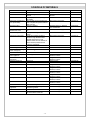
HOME OWNER’S
INFORMATION PACK
for
Chapel Street/Summer Street
ABERDEEN
(Applicable to 45 Summer Street)
www.scotia-homes.co.uk
Please read this document in conjunction with the NHBC booklet ‘Guide to
your new home – A practical guide to looking after your new home’, as
supplied with your Handover Pack.
DRAFT Rev. 2 22.03.12
Contents
Page
OPERATING INSTRUCTIONS FOR GAS-FIRED CENTRAL HEATING, HOT WATER AND
COLD WATER SYSTEMS ____________________________________________________ 3
RADIATOR SAFETY PRECAUTIONS ___________________________________________ 4
BOILER TYPE _____________________________________________________________ 4
GAS SYSTEM______________________________________________________________ 5
HOT AND COLD WATER SERVICES ___________________________________________ 5
KITCHENS ________________________________________________________________ 6
EXTRACTOR FANS _________________________________________________________ 6
WINDOW VENTILATION AND AVOIDING CONDENSATION ________________________ 6
COMMUNAL TELEVISION/ SATELLITE AERIAL INSTALLATION ____________________ 7
TELEPHONE INSTALLATION _________________________________________________ 7
WINDOW OPERATING INSTRUCTIONS ________________________________________ 7
OPERATING INSTRUCTIONS FOR THE ELECTRICAL INSTALLATION _______________ 7
IF AN ELECTRICAL CIRCUIT FAILS ___________________________________________ 8
SMOKE DETECTORS _______________________________________________________ 8
DOOR ENTRY SYSTEM______________________________________________________ 9
DOWNLIGHTS _____________________________________________________________ 9
SPRINKLER SYSTEM _______________________________________________________ 9
FLAT ENTRY DOORS ______________________________________________________ 10
INTERNAL DOORS ________________________________________________________ 11
WALL TILING _____________________________________________________________ 11
ROOF SPACE ____________________________________________________________ 11
CONSTRUCTION OF WALLS, PARTITIONS & CEILINGS__________________________ 12
FIXING TO WALLS, CEILINGS OR FLOORS - IMPORTANT NOTICE_________________ 12
COMMUNAL STAIRWELLS__________________________________________________ 13
METER LOCATIONS _______________________________________________________ 13
SCHEDULE OF MATERIALS_________________________________________________ 14
SCHEDULE OF TEST CERTIFICATES _________________________________________ 13
NOTE:
The information contained in this document is for the standard flat types within the development
and may not cover specific variations requested by you.
-2-
OPERATING INSTRUCTIONS FOR GAS-FIRED CENTRAL HEATING, HOT WATER AND
COLD WATER SYSTEMS
Introduction
Your home has been fitted with a gas-fired heating and hot water system.
The gas-fired boiler is located in the hallway cupboard. You will find the operating and maintenance
instructions for the boiler in your Handover Pack.
You should carry out no adjustments to the boiler. If you are unable to find the answers to any boiler
problems, in the first instance, please contact Scotia Homes.
You are responsible for the annual maintenance and servicing of the boiler, this can be arranged
through any reputable plumbing or gas servicing contractor.
Heating and Domestic Hot Water Controls;
The system has the following controls: -
1. Boiler isolating switch.
2. Heating and Hot Water Programmer (Fitted as part of the Boiler)
3. Thermostatic Radiator valves to radiators.
4. Room Thermostat
5. Frost stat (integral part of the boiler).
1. Boiler isolating switch
This switch is on the wall next to the boiler. This switch is to isolate the electrical supply to the boiler and
should be left on at all times. Only use this switch if a fault develops on the boiler.
2. Heating and Hot Water Programmer
A digital twin channel programmer for the Heating and Hot Water is fitted on the front of the boiler
boiler. It controls the boiler, telling it when your central heating and hot water is required. Your Handover
Pack contains the manufacturer’s installation guide and a user guide for this programmer – please
familiarise yourself with the programmer user instructions. The programmer has numerous ON and OFF
periods, which may be altered to suit your own requirements.
3. Thermostatic Radiator Valves
Thermostatic Radiator Valves are fitted to the radiators for comfort control and to allow you to set the
radiator temperature at a level that gives you the room temperature that you want. i.e. position 1 = low
level heat, 4 = maximum level heat. Depending on level of comfort required, positions 2 – 4 should be
selected. Please refer to the Danfoss User guide in your Handover Pack for full details.
4. Room Thermostat
The room thermostat is located in the hallway – the temperature should be set to meet your own
requirements for the heating. When the temperature setting is reached the thermostat will switch off the
heating function of the boiler. If you find your heating is not working, check that the thermostat has not
been turned down.
-3-
5. Frost stat (integral part of the boiler)
The frost stat is an integral part of the boiler. In severe weather conditions the frost stat can override the
programmer and start up the heating system to warm the water in the boiler and pipework to prevent
damage by freezing – please refer to the boiler frost protection section in your boiler user manual for
more information.
If you are intending to be away from home for a long period of time and there is a possibility of
extremely cold weather while you are away, another option is to shut off your heating and hot water
system and completely drain it down. If in doubt consult a plumber or heating engineer.
Central Heating – Dealing With Faults
Should your central heating or hot water fail to work or develop a fault, please ensure that all of the
procedures laid out in the boiler’s user manual are followed before requesting a call out. Failure to do
this may result in a charge being made for an unnecessary call out.
Bleeding of Radiators
This should not be required with a sealed system. However, radiators feeling warm at the bottom but
cold at the top would indicate that there is air in the radiator. There is an air bleed point normally at the
right top side of radiator. Use an air-bleeding key to turn clockwise to reduce air when the boiler is off.
Tighten securely after air is released. Check pressure gauge on boiler, if it is below that recommended
in the manufacturer’s instructions then it will be necessary to top up the system. See boiler user manual
for the filling method instructions and also more information is contained in your NHBC Guide to your
new home in Section 8 Tips.
RADIATOR SAFETY PRECAUTIONS
All heating radiators can get hot when in use.
The temperature of a radiator is dependent upon the temperature of the system water and the various
heating controls (as described above). These controls are set by the system installer and user.
Users should ensure that those who may come into close proximity to hot radiators are aware of the
risks of burns.
Users should take any necessary steps to minimise the risks of burns from hot radiators (for example
where there are very young people in the room). Where applicable, consideration should be given to
placing guards in front of the radiators or reducing the temperature of individual radiators by turning the
thermostatic radiator valve to a low setting.
BOILER TYPE
Worcester Bosch Gas Fired Combination Greenstar 30Si boiler
The installation, commissioning and servicing instructions (which includes commissioning and service
record) together with the User Manual for your Greenstar wall hung RSF Gas Fired Condensing
Combination Boiler is contained in your instructions package. Please read the user instructions to
familiarise yourself with the safety precautions, controls and operating and maintenance requirements
for your boiler. Also contained in your instructions package is a copy of the Greenstar 60/100 flue
installation manual – this manual also contains important information regarding servicing and
maintenance.
-4-
GAS SYSTEM
Never obstruct gas boiler flue outlets or ventilation to the boiler. Never tamper with the gas installation
or equipment.
If you suspect a gas leak:
1. Extinguish all naked flames
2. Do not use any electrical switches or appliances
3. Turn off the gas at the meter (meter location is identified later under ‘Meter Locations’
4. Open all doors and windows
5. Call the National Gas Emergency Service on its emergency number which is in the phone book
(Business listings) under ‘GAS, Gas Emergency’. The current emergency number at date of
preparation of this document is 0800 111999. This service operates 24 hours a day and 365
days a year. There is no call out charge.
HOT AND COLD WATER SERVICES
Mains Cold Water Service
There is a single mains water service pipe serving all of the flats in your block which rises in the service
duct in the stairwell. The incoming cold water pipe to your flat tee’s off this service pipe riser.
The stopcock (shut off valve) which allows you to shut off your water supply to your flat is located in a
hall cupboard.
There is also a water stopcock in the service riser which can shut off the water supply to your flat – this
is for use only by the water board in an emergency situation.
Tank Cold Water Service – not applicable to your flat.
Thermostatic showers (hot water temperature of showers and bath)
Your bath is fitted with a thermostatically controlled shower valve which also fills the bath through a
separate filler. The temperature of the hot water from the shower valve (when used as a shower or to fill
the bath) is limited to 42 degrees centigrade for your safety (a legal requirement which cannot be
exceeded). It is recommended that an annual check is carried out to test the water temperature to
ensure that the shower has not developed any faults and that the maximum hot water temperature
identified above is maintained. For more details please refer to the shower valve manufacturer’s
instructions contained in your Handover Pack.
Hot Water Temperature (kitchen sink and wash hand basin)
The hot water from your kitchen sink taps and wash hand basin taps can be very hot depending upon
the settings of the boiler. The hot water from the taps can initially have a low temperature as cooler
water sitting in the pipes is discharged but can then become hot suddenly. Appropriate care should be
taken to avoid risks of scalding.
-5-
Sanitaryware/Taps
Sanitaryware should be cleaned in accordance with the manufacturer’s instructions which are enclosed
in your Handover Pack.
The manufacturer of the bath recommends the use of an anti slip mat when using a shower installed
over their bath.
KITCHEN
Kitchen appliances, kitchen sink, kitchen units and worktops
Please refer to the manufacturer’s instructions contained in your Handover Pack for operating and
cleaning instructions for your kitchen appliances, sinks, units and worktops.
Connecting appliances
When fitting a dishwasher or washing machine, please ensure the blanked end of the waste pipe tee
piece has been removed. Note - this is not applicable where a ‘standing waste’ pipe has been provided.
Please also ensure that the water supplies and wastes are securely connected to the pipework.
EXTRACTOR FANS
Bathroom fan
Control switches are located adjacent to light switches.
Fans should be switched on to remove moisture and odour.
Manufacturer’s installation and maintenance information is enclosed within your Handover Pack.
WINDOW VENTILATION AND AVOIDING CONDENSATION
Most windows are fitted with “trickle” ventilators at the top of the windows. These can be opened and
closed to allow more or less ventilation.
Condensation will be a problem in all new homes if adequate background heating and ventilation are
not used, we would suggest that you read carefully the section within the NHBC booklet: ‘GUIDE TO
YOUR NEW HOME’, ‘reducing condensation’, on pages 8 and 9.
The following are general guidelines for your information:
To deal with condensation, take these two steps:
Produce less moisture.
Ordinary daily activities produce a lot of moisture very quickly.
Cooking: To reduce the amount of moisture in the kitchen, cover pans and do not leave kettles boiling,
use your cooker hood extractor fan.
Washing clothes: Put washing outdoors to dry if you can. Or put in the bathroom with the door closed
and the window open or fan on. If you have a tumble dryer, ventilate it to the outside (unless it is the
self-condensing type). DIY kits are available for this.
-6-
Ventilate to remove moisture
You can ventilate your home without making draughts.
Some ventilation is required to expel the moisture which is constantly being produced, mostly just by the
natural breathing of occupants. Keep a small window ajar or a trickle ventilator open when someone is
in the room.
You need much more ventilation in the kitchen and bathroom during cooking, washing up, bathing and
drying clothes. This means using the installed fan or opening windows wider.
Close the kitchen and bathroom doors when these rooms are in use. This helps prevent the moisture
reaching other rooms, especially bedrooms, which are often colder and more likely to get condensation.
COMMUNAL TELEVISION/ SATELLITE AERIAL INSTALLATION
A communal digital wide band TV aerial and a communal satellite dish have been installed and linked to
your flat providing a twin tuner compatible satellite / digital outlet (media plate) in the living area with
cable from the living-room TV point to a TV link amplifier (the amplifier is installed next your electricity
consumer unit) and cables from the amplifier to the bedroom outlet.
TELEPHONE INSTALLATION
Telephone points are located beside each TV point in the living area and bedroom area; it is compatible
with any British Telecom approved phone.
It is your responsibility to arrange connection to your chosen telephone service provider.
WINDOW OPERATING INSTRUCTIONS
Your flat is fitted with an inwards opening tilt and turn window in the bathroom and Velux roof windows
in the living and bedroom areas. These windows have standard (non-locking) handles.
Please refer to the ‘NorDan Operator’s manual with safety guidelines’ for your tilt and turn bathroom
window for operating instructions and safety recommendations when cleaning. A copy is contained in
your Handover Pack.
Please refer to the Velux window instructions contained in your handover Pack for the living and
bedroom area roof windows.
SAFETY RECOMMENDATION – if you have young children we recommend that you give consideration
to having additional child safety catches fitted to your windows.
OPERATING INSTRUCTIONS FOR THE ELECTRICAL INSTALLATION
CONSUMER UNIT
The consumer control unit for your property is located in the hallway cupboard; it contains a labelled
main isolator, residual current devices (RCDs) and miniature circuit breakers (MCBs), or “trip switches”
for each circuit in the property.
This is a device that controls the electricity supply to your home, splitting the incoming mains electricity
into the various electrical circuits around your home.
-7-
The consumer control unit contains a Main Switch, RCBO’s (Residual Current Operated Circuit
Breaker), RCD and MCBs. The main switch is normally ‘ON’ - in order to isolate all supplies, switch to
‘OFF’.
These circuit breakers and RCDs are designed to ‘trip’ if there is a fault in a circuit, or if a faulty
appliance is switched on. This helps to prevent serious accidents that may result in damage and injury.
Under fault conditions these will be in the ‘tripped position’ (Off position).
To reset and for testing regime, follow the manufacturer’s instructions contained in your Handover Pack
– in particular refer to the Consumer Unit manufacturer’s User Operating instructions which are
contained in your Handover Pack.
We recommend that you have your electrical installation tested by an electrician every 5 years.
Note: Electricity is dangerous and can kill. If you are unsure of any aspect
of your electrical installation please consult a qualified electrical contractor.
IF AN ELECTRICAL CIRCUIT FAILS
A circuit may trip OFF. If this happens, you should follow the procedure set out below.
1.
Check (with aid of torch if necessary) whether the RCD (mid position) or MCB (fully down) is in
the OFF position.
2.
Switch RCD (press down then push to the fully up position) or MCB to ON position.
3.
If the RCD does not re-set switch off all the MCB’s, re-set the RCD then switch on each MCB
individually until the faulty circuit is identified.
4.
To identify the cause of the fault switch off all appliances in that circuit, re-set the RCD and
MCB, then switch back on each appliance until the defective appliance is found.
Please also refer to the Consumer Unit manufacturer’s instructions contained in your Handover Pack.
Over filling kettles, irons etc. can cause this type of fault.
N.B. It is important to ensure that the bulbs used in light fittings do not exceed the rating for that fitting.
SMOKE DETECTOR
Your flat is fitted with a smoke detector in the hallway. The smoke detector is mains operated with
battery back up and connected to its own circuit in the consumer control unit. It is extremely sensitive to
smoke and dust particles of any kind.
To test the smoke detector, firstly ensure that it is receiving power by looking at the green mains
indicator light on the cover is lit. Secondly, press the test button firmly for 10 seconds until the alarm
sounds and the red light on the cover flashes rapidly. If the alarm horn makes a continuous sound and
you have not pushed the test button, the detector has sensed smoke or dust in the air. This could be
your warning of a possible serious situation requiring immediate attention.
If on thoroughly checking the property, no trace is found, it could be a nuisance alarm caused by
cooking smoke or something similar. If this occurs, open a window to clear the smoke or dust and the
alarm will cease or press the test/hush button to silence the alarm.
Please refer to the Ei Electronics User Instructions for more detailed information – a copy is contained in
your instructions package.
-8-
DOOR ENTRY SYSTEM
Maintenance
The door entry system will be maintained by the factor. If a fault is found or suspected in the door entry
system please report it to the factor.
Operating instructions for door entry Handset
When a visitor pushes your flat number on the door entry panel beside the front door your handset will
‘ring’. To speak to the visitor lift the handset and this will connect you to the door entry panel. If you wish
to let them into the building press the button marked with a key – which will release the lock on the door.
The service button on the door entry panel is to allow access for postmen and the like to your building
during a set time period to make deliveries. The service button has been set for 7am to 11am. When the
service button is pushed on the panel at the front door between these times it will automatically open
the door.
Power failure – in the event of a power failure the front door will automatically unlock (this is to ensure
that access for firemen or other emergency services is maintained if the door entry system is not
working due to a power failure).
DOWNLIGHTS
Your flat has JCC mains voltage recessed down-lighters fitted. The manufacturer recommends fitting
their own brand replacement lamps in this fitting – please refer to the manufacturer’s information
contained in your Handover Pack. The manufacturer also recommends the following;
Always switch off mains supply before servicing, fitting or replacing lamps.
Always check the lamp is correct for the application, including its voltage and wattage.
Never exceed the maximum wattage.
Ensure the lamp is correctly located in the lamp-holder.
SPRINKLER SYSTEM
PLEASE ALSO REFER TO THE SEPARATE SHEETS DETAILING HOW THE SPRINKLER SYSTEM
COMPONENTS OPERATE
Your flat has an automatic life safety suppression system (a sprinkler system) installed for your safety.
The sprinkler system is a stand alone fire safety system and is not linked to the separate smoke
detection system contained in the flat (see above for more information on the smoke detectors). Smoke
from, for example, burned toast may activate your smoke detector but it will not activate your sprinkler
system – it takes the direct application of a high heat (such as from flames) to activate the sprinkler
system.
The sprinklers are hidden behind white cover plates in your ceiling. When activated by a fire (or other
source of very high temperatures) the cover plate will fall away and the sprinkler head will drop and
spray water – the following points should be noted regarding the sprinkler system;
1. Upon activation of any sprinkler head, audible warning sounders will also activate in the flat
with the activated sprinkler and also all the other flats in your block – this is to warn you and
other flat residents in the block that there is a fire in one of the flats.
-9-
2. Once activated the sprinkler will operate until the water is shut off by using an isolating valve at
the bottom of the sprinkler riser pipe -only the factor which can access the sprinkler shut off
valve.
3. Individual flats cannot be isolated from the sprinkler system – for the system to operate as
required the system must be live at all times.
4. There is no maintenance required to the sprinkler pipework or sprinkler heads within the flats
5. You must not wallpaper or paint over the sprinkler head cover plates- painting or wallpapering
over these sprinkler head cover plates would impair their operation.
6. You should not remove or otherwise handle the sprinkler head cover plates – if you have any
queries regarding the sprinkler system installed in your flat please contact the factor.
The type of sprinkler systems installed at Chapel and Summer Streets are mains water fed (they do not
have water storage tanks). Each system incorporates a priority valve on the incoming water supply
which is held open by a power supply from the sprinkler control panel. In the event of the sprinkler
system activating, the priority valve shuts off the water supply to the domestic water riser pipe and
diverts all water to the sprinkler system to ensure that the maximum possible flow of water is available
to the sprinkler system.
As this is a life saving fire fighting system, in the event of an electricity power cut to the building, the
priority valve will also automatically shut off the domestic water supplies –the reason for this is that in a
fire there is a good chance that the electricity will shut off and in order for the sprinkler systems to
remain effective they must have the full pressure of water available. It should be noted that, in a power
cut, the domestic water supply is shut off to maintain the maximum effectiveness of the sprinkler
system.
FLAT ENTRY DOORS
Introduction
Your flat entrance door is a high performance fire rated security door-set.
Door Closer
The flat entry door has been fitted with a Briton overhead door closer to ensure that the door is self
closing. Occupants should not disconnect or otherwise restrict the operation of the overhead door closer
as its function is to ensure that the flat entrance door closes by itself in order to maintain the fire
resistant integrity of the flat.
Door Operating Instructions
To lock the flat entry door from the inside lift the handle (to activate the multi point locking) and return it
to the horizontal then turn the thumb-turn fully towards the locking side of the door. To open the door
from the inside, turn the thumb-turn in the opposite direction.
To lock the door from the outside lift the handle and return it to the horizontal and turn key fully towards
the locking side of the door. Open the door by turning the key in the opposite direction.
Basic instructions for locking the doors can also be found on the edge of the door leaf.
NOTE- Excessive force should not be required or used to lock and unlock the doors.
Cleaning Instructions
Clean the door with a liquid detergent (we suggest a normal washing up detergent) applied with a soft
sponge or soft cloth. Wipe from top down to dry.
- 10 -
Handles should be cleaned with a soft non abrasive cloth and for stubborn stains mild soapy water may
be used. Care should be taken to avoid scratching surface of the handles.
Smoke Seals
If any damage occurs to the door seals or threshold or to the intumescent strips surrounding the door
(part of the fire door protection) or if any unequal gaps form between the door leaf and its frame then
this must be repaired immediately.
INTERNAL DOORS
The internal door from the hallway to the living room/ kitchen area is fire resistant and is fitted with an
overhead door closer. As with the flat entry door, this door closer is for your safety and you must not
disconnect or otherwise restrict the operation of the overhead door closer as its function is to ensure
that the door closes by itself in order to maintain the fire security for the occupants.
The door is also fitted with integral smoke and intumescent fire seals (recessed into the door side and
top frames)- the brush seals are to protect from smoke and must not be over-painted as this will reduce
their effectiveness. The operation of the door closer and the integrity of the fire and smoke seals should
be checked periodically and repaired if any defect is found.
If replacing this internal door leaf an FD30 fire resistant door specification and fire rated ironmongery
must be used.
The hall cupboard doors are also fire resistant (although they do not require overhead door closers
when fitted with a lock).
Cleaning Instructions
Clean the door with a liquid detergent (we suggest a normal washing up detergent) applied with a soft
sponge or soft cloth. Wipe from top down to dry.
Handles should be cleaned with a soft non abrasive cloth and for stubborn stains mild soapy water may
be used. Care should be taken to avoid scratching the surface of the handles.
WALL TILING
Wall Tiles and in particular the grout between the tiles should be regularly cleaned using a proprietary
tile/grout cleaner in accordance with the cleaner’s instructions.
Grout should be inspected and any areas which become loose should be replaced.
The sealant between the tiles and Sanitaryware should be inspected and replaced as necessary.
ROOF SPACE
The attic space has not been designed to allow for storage. Flooring the roof space and using the attic
for storage may cause deflection in the roof structure. Do not use the attic space for storage.
The attic has mineral wool insulation between and over the ceiling joists. This insulation can cause skin
irritation (if in direct contact with the insulation). If handling the insulation protective clothing is
recommended.
- 11 -
Care should be taken if entering the attic space – the ceiling plasterboard between the joists will not
support your weight and there may be service pipes and cables hidden by the insulation that you can
damage by inadvertently stepping on them. Also the attic access door is not a structural product and
must not be walked or stepped on.
It is advised that you do not enter the attic space.
CONSTRUCTION OF WALLS, PARTITIONS & CEILINGS
External Walls:
A cavity wall comprising a 100mm thick block work with render outer
leaf, 50mm wide cavity and 140mm block work inner leaf. To the inside
of the cavity block work wall there is a 70mm thick layer of high
performance insulation with a timber framed service void with a
plasterboard inner leaf.
All Partitions:
70mm timber studwork partitions with plasterboard to each side.
Floor Construction:
22mm flooring fixed to timber battens installed into a sound absorbing
cradle flooring system on precast hollowcore floor units
Ceilings with attics above:
Plasterboard fixed to factory made timber roof trusses (with attic
insulation installed between and over the truss bottom chords).
SAFETY NOTE –
There are services, pipes and cables located within the external walls,
partitions, ceiling voids, attic spaces and in the floors between the
battens.
SAFETY NOTE -
The flat hall partition walls and ceilings have been constructed to a fire
resistant specification – if, in the future, you should consider making any
internal alterations to the flat layout (such as removal of an internal
partition or forming an opening through an internal partition) then the
alterations should be checked first with a suitably qualified person
(such as an Architect) before they are made to avoid any chance of
reducing the effectiveness of the fire protection measures incorporated
within your flat.
FIXING TO WALLS, CEILINGS OR FLOORS - IMPORTANT NOTICE
Wall fixings (for pictures, mirrors etc.) must be of the appropriate type for the type of walls described
above. Be very careful if nailing or drilling into walls and ceilings to avoid contact with any pipes or
electric cables which may lie behind the plasterboard. We recommend that you use a services detector
(cable detector) before drilling or nailing – it can reduce the risk of serious accidental injury. If using
power tools to install a fixing use an R.C.D. (residual current device). You should also always check for
pipes and cables before drilling or nailing into floors.
Fixings should never be made to the following wall areas: a) Directly above or below any electrical socket outlet, switch or appliance.
b) Directly horizontal to any electrical socket outlet, switch or appliance.
This is because electrical cables run in these areas.
Please also refer to your NHBC ‘Guide to your new home’ - Section 7, for more information
- 12 -
COMMUNAL STAIRWELLS
The communal staircases will be maintained by the factor. For your information please note the
following points;
1. The windows in the communal stairwells are fitted with automatic opening devices (for use by
the fire brigade only) to disperse any smoke arising from a fire. It is not possible to open these
stairwell windows and for safety reasons the automatic opening devices (actuators) must not
be uncoupled from the windows.
2. Stairwell front doors (and back doors where applicable) are fitted with overhead door closers to
ensure that the doors are self closing. This is for your safety and security – please do not
disconnect or otherwise restrict the operation of these door closers. All stairwell doors should
be securely closed after use.
3. As well as being covered by the same sprinkler system as your flats (as described above) the
stairwell also has a ‘stand alone’ smoke detector system to warn you if smoke is detected in
the stairwell.
4. Stairwell lighting – the stairwell lighting includes emergency lighting (with battery back ups
fitted). In the event of any loss of power these emergency lights will come on to allow the stairs
to be used safely. These lights will be maintained by the factor - if a stairwell light fails please
contact the factor.
METER LOCATIONS
Location of the electrical meter - in hall cupboard (to left hand side).
Location of the gas meter – in hall cupboard (to right hand side).
SCHEDULE OF TEST CERTIFICATES
Including commissioning certificates/records;
BOILER
Installation, commissioning and service record logbooks. (with your instruction manual package)
- 13 -
SCHEDULE OF MATERIALS
Item
Bathroom Window
Velux windows
Internal Doors
Internal door overhead door
closer (where fitted)
Flat Entrance Door
Flat entrance door
overhead door closer
Internal finishings
Internal Door ironmongery
Paint to walls
Paint to ceilings
Paint to woodwork (skirting
boards / facings etc.)
Ceramic Tiles
Kitchen Units, Worktops &
kitchen appliances
Mirrored kitchen worktop
splash backs
Ventilation extract fans
Electrical switches / sockets
Bath
Description
Nordan Prefinished Timber
Velux top hung and cabrio balcony
windows
Premdor pre-primed flush paint grade
plus (FD30)
Geze TS1500 size 3-4 overhead door
closer complete with polished stainless
steel cover cap
Swedoor FD30S E6
Briton 2130B overhead door closer size
2-6
MDF Square Skirting boards and
facings
Internal door handles: M. Marcus
transitions range GC5844 Catullo
polished chrome lever on rose.
Bathroom thumb-turn and release; M.
Marcus GC0775 polished chrome
thumb-turn and release.
Glidden Trade Contract Matt White
Glidden Trade Contract Matt White
Dulux trade Eggshell
As client’s choice
Hacker Rigid Built kitchen furniture
Mirror splash backs
Greenwood
MEM
Carron Quantum
Bath shower screen
Merlyn Folding Screen
Shower valve
Hansgrohe Ecostats
Shower head and rail
Hansgrohe Croma 100
Sanitaryware
Laufen
Taps
Hansgrohe Chrome
Boiler
Heating and Hot Water
Programmer
Radiators
Radiator valves
Worcester Bosch gas fired boiler
Worcester Bosch DT20 Digital Twin
Channel Programmer
Myson Premier HE
Danfoss RAS-C2 to radiators and RASD2 chrome fitted to towel rails
- 14 -
Supplied by
Nordan UK Ltd, Aberdeen
Keyline Builders Merchants,
Dundee
Orchard Timber Products, Forfar
Tel No.
01224 854600
01382 448600
Build Centre Ironmongery
01224 591777
Architectural Doors + Windows
Ltd, Cumbernauld
Build Centre Ironmongery
01236 780022
Orchard Timber Products, Forfar
01307 474800
Build Center Ironmongery
01224 591777
Dulux Decorator Centre
Dulux Decorator Centre
Dulux Decorator Centre
01224 573044
01224 573044
01224 573044
Porcelanosa
Laings Bathrooms, Bedrooms
Kitchens, Inverurie
Laings Bathrooms, Bedrooms
Kitchens, Inverurie
Holland House
Holland House
Laings Bathrooms, Bedrooms,
Kitchens, Inverurie
Laings Bathrooms, Bedrooms,
Kitchens, Inverurie
Laings Bathrooms, Bedrooms,
Kitchens, Inverurie
Laings Bathrooms, Bedrooms,
Kitchens, Inverurie
Laings Bathrooms, Bedrooms,
Kitchens, Inverurie
Laings Bathrooms, Bedrooms,
Kitchens, Inverurie
Northern Heating
Northern Heating
0141 533 1002
01467 626368
Northern Heating
Northern Heating
01224 663322
01224 663322
01307 474800
01224 591777
01467 626368
01224 638129
01224 638129
01467 626368
01467 626368
01467 626368
01467 626368
01467 626368
01467 626368
01224 663322
01224 663322