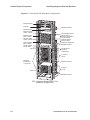
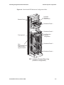
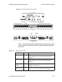
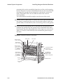
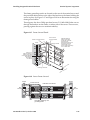
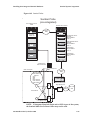
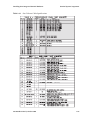
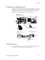
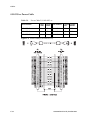
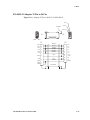
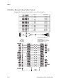
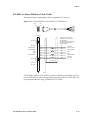
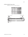
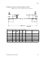
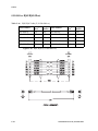
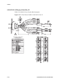
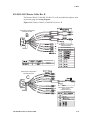
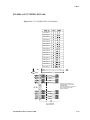
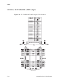
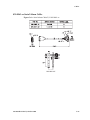
1
Tekelec Signaling Products Integrated Applications Installation Manual Table of Chapters Table of Contents List of Figures List of Tables List of Procedures Chapter 1. Introduction Chapter 2. Sentinel Sytem Components Appendix A. LEDs Appendix B. Connectors Appendix C. Cables Appendix D. Power Cords to Peripherals Index 910-4626 Revision D, October 2004 910-4626 Revision D, October 2004 Tekelec Signaling Products Integrated Applications Installation Manual 910-4626 Revision D October 2004 Copyright© 2002, 2003, 2004 Tekelec. All Rights Reserved Printed in U.S.A. Notice Information in this documentation is subject to change without notice. Unauthorized use or copying of this documentation can result in civil or criminal penalties. No part of this documentation may be reproduced or transmitted in any form or by any means, electronic or mechanical, including photocopying or recording, for any purpose without the express written permission of an authorized representative of Tekelec. Other product names used herein are for identification purposes only, and may be trademarks of their respective companies. Any export of Tekelec products is subject to the export controls of the United States and the other countries where Tekelec has operations. Trademarks The Tekelec logo, EAGLE, G-Flex, G-Port, IP7, and IP7 Secure Gateway are registered trademarks of Tekelec, Inc. ASi, EAGLE 5, GenuOne, IP7 Front End, SXi, TekServer, TekWare, and VXi are trademarks of Tekelec, Inc. All other trademarks are the property of their respective owners. Patents This product is covered by one or more of the following U.S. and foreign patents: U.S. Patent Numbers: 6,327,350 6,662,017 6,456,845 6,647,113 5,953,404 6,606,379 6,167,129 6,324,183 6,639,981 5,008,929 Ordering Information Additional copies of this document can be ordered from Tekelec Network Signaling Division, 5200 Paramount Parkway, Morrisville, North Carolina, 27560 Table of Contents Chapter 1. Introduction Safety Information.................................................................................... 1-3 Admonishments and Conventions ........................................... 1-3 Post-Installation Inspection .............................................................. 1-5 Introduction............................................................................................... 1-7 Regulatory, Safety Compliance and Certification......................... 1-8 Environmental Requirements .......................................................... 1-9 Temperature Variation ............................................................... Relative Humidity....................................................................... Elevation ....................................................................................... Building Requirements............................................................... 1-9 1-9 1-9 1-9 Scope and Audience............................................................................... 1-10 Signaling Products Systems .................................................................. 1-11 Integrated Application Products ................................................... 1-12 Sentinel........................................................................................ 1-12 Documentation ....................................................................................... 1-13 About this Manual ........................................................................... 1-13 Documentation Suite ....................................................................... 1-13 Documentation Packaging, Delivery, and Updates.................... 1-17 References ......................................................................................... 1-17 Product Packaging and Delivery ......................................................... 1-18 Tekelec Technical Support .................................................................... 1-18 Installation Support ......................................................................... 1-18 Hardware Operational Testing Support....................................... 1-19 Tekelec Customer Services ............................................................. 1-19 Problem – Critical ...................................................................... Problem – Major ........................................................................ Problem – Minor........................................................................ Response ..................................................................................... Emergency Response ................................................................ 1-19 1-20 1-20 1-21 1-21 Hardware Repair and Return ............................................................... 1-22 Obtaining a Return Material Authorization (RMA) ................... 1-22 Repair and Return Shipping Instructions .................................... 1-22 910-4626 Revision D, October 2004 i List of Figures General Instructions .................................................................. 1-22 Returning a Shipping Container.............................................. 1-23 Acronyms ................................................................................................. 1-24 Doc Assignments (from SW perspective)............................................ 1-30 Systems Components Overview........................................................... 1-32 Module Installation................................................................................. 1-35 Hardware Operational Testing ............................................................. 1-35 Chapter 2. Sentinel Sytem Components Safety Information .................................................................................... 2-3 Introduction ............................................................................................... 2-4 Installing Integrated Sentinel Hardware ............................................... 2-5 Expanded Services Platform ............................................................. 2-5 Breaker Panels................................................................................... 2-10 Break-Out Box ................................................................................... 2-12 Ethernet Switches ............................................................................. 2-13 Installation of Ethernet Switches.................................................... 2-15 Routers ............................................................................................... 2-19 Servers Model 120 ............................................................................ 2-20 Server Model 120 Features........................................................ 2-21 Adding Servers to the Netra-based ESP Frame ........................... 2-22 Integrated Sentinel ESP Cabling .................................................... 2-26 Integrated Sentinel ESP TO-FROM Table ..................................... 2-34 Installing Non-integrated Sentinel Hardware .................................... 2-38 Site Collector, i2000 Frame .............................................................. 2-42 Breaker Panels (2)(P/N 870-2248-04) ...................................... 2-42 Site Collector, Break-Out Box ......................................................... 2-43 Hub .............................................................................................. 2-44 Flight Recorders ......................................................................... 2-45 i2000 Shelves............................................................................... 2-47 Site Collector, i2000 Frame, Interconnect ...................................... 2-50 Installng the Sentinel Server Frame...................................................... 2-54 Server Frame, BP............................................................................... 2-56 Server Frame, Switch ....................................................................... 2-56 Server Frame, Console Server......................................................... 2-58 Server Frame, Interconnect ............................................................. 2-61 Packet Backplane Chassis ...................................................................... 2-64 Taking ESD and Antistatic Precautions.................................. 2-65 ii 910-4626 Revision D, October 2004 List of Figures PBC Handling the Chassis ....................................................... 2-66 Appendix A. LEDs Circuit Card LEDs ................................................................................... A-2 Introduction ....................................................................................... A-2 ATM E1/T1 Card P/N 870-2698-01 ............................................... A-2 ATM-LIM, AINF-LIM, E1-LIM, EILA, ILA................................... A-3 DCM and DSM, Database Module................................................. A-4 E1/T1 MIM, ....................................................................................... A-5 General Purpose Service Module (GPSM-II) ................................ A-6 GR-376 Processor .............................................................................. A-7 HMUX, High-Speed Multiplexer (Eagle STP only) ..................... A-8 MCAP, MAS Communications Applications Processor ............. A-9 MDAL, Maintenance Disk and Alarm Card ............................... A-10 MPL-LIM, Multi-Port LIM............................................................. A-11 MPLT, Multi-Port LIM with Taxi Component ........................... A-12 Integrated Applications LEDs ............................................................. A-13 Breaker Panel LEDs ........................................................................ A-14 Host Server LEDs............................................................................ A-15 Hub LEDs......................................................................................... A-16 Router LEDs..................................................................................... A-17 Expanded Services Platform (ESP) Ethernet Switches .............. A-18 TAS, Tone and Announcement Server LEDs.............................. A-20 Appendix B. Connectors Control Shelf Modules ............................................................................. B-4 ACM/ASM/DCM/DSM/EILA/ILA/LIM/MPL/TSM Control Shelf Backplane Pin-Outs, Top Connector.................. B-4 ACM/ASM/DCM/DSM/EILA/ILA/LIM/MPL/TSM Control Shelf Backplane Pin-Outs, Bottom Connector ............ B-6 Extension Backplane (P/N 850-0356-01)............................................... B-9 Extension Shelf Backplane (P/N 850-0356-01) .............................. B-9 General Purpose Relay Connector 01 .................................................. B-10 General Purpose Relay Connector 02 .................................................. B-11 General Purpose Serial Interface .......................................................... B-12 Interface Backplane Control.................................................................. B-13 Interprocessor Message Multiplexer Control Shelf ........................... B-15 Control Shelf IPMX A Backplane P8 ............................................. B-15 Control Shelf IPMX B Backplane P24............................................ B-17 910-4626 Revision D, October 2004 iii List of Figures Interprocessor Message Multiplexer Extension Shelf....................... B-20 Interprocessor Message Transport Connector................................... B-22 Local Maintenance Center Alarm Backplane..................................... B-23 Power Connector Extension Backplane .............................................. B-24 Power Connector Control Backplane.................................................. B-25 Remote Maintenance Center Alarm Control Backplane .................. B-26 Serial Port Control Backplane .............................................................. B-27 Shelf Power ............................................................................................. B-28 Shelf Power Connector P1, P2, P3 .......................................... B-28 Appendix C. Cables Cables by Part Numbers ......................................................................... C-1 Labeling ..................................................................................................... C-4 Cable Labeling ................................................................................... C-4 Introduction .............................................................................................. C-6 803-0029-01 MPL Card Diagnostic Cable ............................................. C-7 804-0176-01 Converter ............................................................................. C-7 804-1830-01 Coaxial Cable Adapter....................................................... C-8 830-0224-xx Drive Power Cable ............................................................. C-9 830-0231-xx Local Maintenance Center Cable ................................... C-10 830-0232-xx Row Alarm Cable ............................................................. C-11 830-0233-xx Remote Maintenance Center Cable ............................... C-12 830-0257-xx Hazard Ground Cable ..................................................... C-13 830-0315-xx Power Cable ...................................................................... C-14 830-0366-xx Interface Cable .................................................................. C-15 830-0421-xx CD ROM Cable ................................................................. C-16 830-0425-01 Adapter 15 Pin to 26 Pin.................................................. C-17 830-0435-xx External Alarm Cable (Custom)..................................... C-18 830-0543-xx Alarm Holdover Clock Cable ......................................... C-19 830-0527-xx RS232 .................................................................................. C-20 850-0514-01 Serial I/O Transition Card .............................................. C-21 830-0531-03 Serial Interface Adapter/MODEM ................................ C-22 830-0531-01 Serial Interface Converter Cable .................................... C-23 830-0528-01 Terminal/Converter Cable ............................................. C-24 830-0531-02 Serial Interface, Terminal and Printer Adapter ........... C-25 830-0535-xx Terminal/Printer Cable................................................... C-26 830-0622-xx E1 Cable ............................................................................. C-27 830-0624-xx BNC to BCN Cable Assembly, ....................................... C-28 iv 910-4626 Revision D, October 2004 List of Figures 830-0625-xx BNC/Open End Cable .................................................... C-29 830-0638-xx Filter Rack Alarm Cable.................................................. C-30 830-0651-xx –48V Power Cable............................................................ C-31 830-0680-01 RJ-11 to RJ-11 .................................................................... C-32 830-0656-01 Fifty Position Hard Drive I/O Cable ............................ C-33 830-0708-xx MMI Port Cable................................................................ C-34 830-0709-xx Modem/Terminal Cable................................................. C-35 830-0710-xx Network Cable ................................................................. C-36 830-0711-xx DCM, 100-BASE TX Interface ........................................ C-37 830-0715-xx Ground Cable (2 Hole Lug)............................................ C-38 830-0723-xx Crossover (CAT-5) Cable................................................ C-39 830-0724-xx Data Cable (SXi rev D) .................................................... C-40 830-0724-xx Straight Trough Cable (CAT-5) ..................................... C-41 830-0759-xx Null Modem Cable .......................................................... C-42 830-0763-01 Loop Back Cable Adapter............................................... C-43 830-0772-xx Multi-Port LIM DS0 Cable.............................................. C-44 830-0788-xx Straight Through, Patch Panel Cable ............................ C-45 830-0788-xx Router, Hub, Network GR-376 Cable ........................... C-45 830-0789-xx Crossover DCM Patch Panel Cable............................... C-46 830-0788-xx Router, Hub, Network GR-376 Cable ........................... C-46 830-0814-xx Multi-Port Power Cable .................................................. C-47 830-0822-01 Ground Cable ................................................................... C-48 830-0830-01 Ground Cable ................................................................... C-49 830-0846-01 High Speed Master Timing Adapter............................. C-50 830-0849-xx DS1 Cable.......................................................................... C-51 830-0859-xx Null-MODEM for Terminal ........................................... C-52 830-0866-xx Breaker to Terminal Strip Power Cable........................ C-53 830-0868-xx Power Cable...................................................................... C-54 830-0869-xx Router Power Cable......................................................... C-55 830-0872-xx RAID Power Cable ......................................................... C-56 830-0892-xx Multi-Port DS0 Cable (24 AWG) ................................... C-57 830-0814-xx SXi Data Cable.................................................................. C-58 830-0857-01 HMUX Adapter Cable..................................................... C-59 830-0884-01 Switch to Frame Ground Cable ..................................... C-60 830-0888-xx RJ45/RJ45 Cable (Yellow)............................................... C-61 830-0889-xx RJ45/RJ45 (Blue) .............................................................. C-62 830-0894-xx T1 MIM LIM Cable .......................................................... C-63 910-4626 Revision D, October 2004 v List of Figures 830-0895-01 T1 LIM to MPL Cable Adapter....................................... C-64 830-0900-xx Alarm NETRA Server Cable........................................... C-65 830-0901-xx Tone and Announcement Server Alarm Cable............ C-66 830-0906-01 Serial IF Cable Rev A ....................................................... C-67 830-0907-xx Power Cable Rev A, ......................................................... C-68 830-0908-xx Power Ring ........................................................................ C-69 830-0913-01 J1 Router Cable Rev B ...................................................... C-70 830-0913-02/03 Router Cable Rev B .................................................... C-71 830-0917-01 RJ45 to 9 Pin, Adapter...................................................... C-72 830-0948-xx E1/T1 MIM LIM Cable.................................................... C-73 830-0949-xx E1/T1 MIM LIM to MPL Adapter ................................. C-74 830-0961-xx Serial Alarm Cable ........................................................... C-75 830-0963-xx DB9 F to DB15 M Serial Cable ........................................ C-76 830-0965-xx TekServer Power Cable ................................................... C-77 830-0970-xx Null Modem Assembly Cable ........................................ C-78 830-0972-01 TekServer Serial DB44 to DB9 (X4) ................................ C-79 830-0959-01 ATM E1-T1 Cable ............................................................. C-80 830-0987-01 ATM E1-T1 Cable ............................................................. C-81 850-0496-01 Force Transition Card ...................................................... C-82 Fan Orientation Wiring Diagram TekServer...................................... C-83 Appendix D. Power Cords to Peripherals International Power Cords ..................................................................... D-2 Index vi 910-4626 Revision D, October 2004 List of Figures Figure 1-1. Removing Modules .................................................................. 1-35 Figure 2-1. Eagle STP and Integrated Sentinel Diagram .......................... 2-5 Figure 2-2. Integrated Sentinel Frames ....................................................... 2-7 Figure 2-3. Netra-based ESP Maximum Configuration ........................... 2-8 Figure 2-4. Netra-based ESP Minimum Configuration Rear ................... 2-9 Figure 2-5. Breaker Panel Front and Rear ................................................. 2-11 Figure 2-6. Break-Out Box ........................................................................... 2-12 Figure 2-7. Ethernet Switches Maximum Configuration ....................... 2-13 Figure 2-8. Ethernet Switches ..................................................................... 2-15 Figure 2-9. Ethernet Switches Assembly .................................................. 2-15 Figure 2-10. Ethernet Switches Ground Strap .......................................... 2-17 Figure 2-11. Ethernet Switches Connections ............................................ 2-18 Figure 2-12. Sentinel Router Front and Rear ............................................ 2-19 Figure 2-13. Adding ESP Server to Frame ................................................ 2-23 Figure 2-14. Adding a Server ...................................................................... 2-23 Figure 2-15. Server Model 120 Front ......................................................... 2-24 Figure 2-16. Server Model 120, 1A and 1B Rear ...................................... 2-24 Figure 2-17. Frame Ground Detail ............................................................. 2-25 Figure 2-18. Server Frame Ground ............................................................ 2-25 Figure 2-19. ESP BP Cabling ....................................................................... 2-26 Figure 2-20. ESP Interconnect ..................................................................... 2-27 Figure 2-21. ESP Interconnect ..................................................................... 2-28 Figure 2-22. ESP Interconnect ..................................................................... 2-29 Figure 2-23. ESP Interconnect ..................................................................... 2-30 Figure 2-24. ESP Interconnect .................................................................... 2-31 Figure 2-25. Sentinel Probe ......................................................................... 2-39 Figure 2-26. Site Collector, i2000 Frame .................................................... 2-41 Figure 2-27. Site Collector, i2000 Frame .................................................... 2-42 Figure 2-28. Break-Out Box Assembly ...................................................... 2-43 Figure 2-29. HUB (P/N 870-2224-01) ........................................................ 2-44 Figure 2-30. Flight Recorders A, B, and C Cabling ................................. 2-45 Figure 2-31. Site Collector Frame, i2000 Cabling ..................................... 2-46 910-4626 Revision D, October 2004 vii List of Figures Figure 2-32. i2000 Shelf ................................................................................2-47 Figure 2-33. i2000 Shelf Installation ...........................................................2-48 Figure 2-34. Site Collector Frame, Rear .....................................................2-49 Figure 2-35. Site Collector, BP .....................................................................2-50 Figure 2-36. Site Collector, Interconnect ....................................................2-51 Figure 2-37. Site Collector, Interconnect ....................................................2-52 Figure 2-38. Sentinel Server Frame ............................................................2-55 Figure 2-39. Ethernet Switch (P/N 804-1580-01) ......................................2-56 Figure 2-40. Console Server .........................................................................2-58 Figure 2-41. Sentinel Server Frame Console Server .................................2-58 Figure 2-42. Server Frame Console Server ................................................2-58 Figure 2-43. Sentinel Server Frame Console Server .................................2-59 Figure 2-44. Server Frame, BP .....................................................................2-61 Figure 2-45. Server Frame, Interconnect ....................................................2-62 Figure A-1. LIM LEDs ...................................................................................A-3 Figure A-2. DCM LEDs .................................................................................A-4 Figure A-3. E1/T1 MIM (P/N 870-2198-01) ..............................................A-5 Figure A-4. GPSM-II P/N 870-2360-01 .......................................................A-6 Figure A-5. GR-376 LEDs .............................................................................A-7 Figure A-6. HMUX LEDs ..............................................................................A-8 Figure A-7. MCAP LEDs ..............................................................................A-9 Figure A-8. MDAL LEDs ............................................................................A-10 Figure A-9. MPL (P/N 870-2061-xx) LEDs ..............................................A-11 Figure A-10. MPLT LEDs ...........................................................................A-12 Figure A-11. Breaker Panel LEDs ..............................................................A-14 Figure A-12. Host Server LEDs ..................................................................A-15 Figure A-13. Hub Front View ....................................................................A-16 Figure A-14. Front View Routers .............................................................A-17 Figure A-15. Rear View Isolation Router .................................................A-17 Figure A-16. Rear View Dial-in Router ....................................................A-17 Figure A-17. Ethernet Switch .....................................................................A-18 Figure A-18. TAS - Front View ..................................................................A-20 Figure B-1. ACM/ASM/DCM/DSM/EILA/ILA/LIM/MPL/TSM Control Shelf Backplane Pin-Outs, Top Connector ............................. B-4 Figure B-2. ACM/ASM/DCM/DSM/EILA/ILA/LIM/MPL/TSM Control Shelf Backplane Pin-Outs, Bottom Connector ....................... B-6 Figure B-3. Extension Shelf Backplane (P/N 850-0356-01) ...................... B-9 viii 910-4626 Revision D, October 2004 List of Figures Figure B-4. General Purpose Relay Connector 01 ...................................B-10 Figure B-5. General Purpose Relay Connector 02 ...................................B-11 Figure B-6. General Purpose Serial Interface Connector 01, GPSI ........B-12 Figure B-7. Interface Connector .................................................................B-13 Figure B-8. Control Shelf IPMX A Backplane Pin-Outs .........................B-15 Figure B-9. Control Shelf IPMX B Backplane Pin-Outs ..........................B-17 Figure B-10. IPMX Extension Shelf Backplane Connector P9 ................B-20 Figure B-11. IMT Connector .......................................................................B-22 Figure B-12. Local Maintenance Center Alarm Connector ....................B-23 Figure B-13. Power Connector ...................................................................B-24 Figure B-14. Power Connector ...................................................................B-25 Figure B-15. Remote Maintenance Center Alarm Connector ................B-26 Figure B-16. Serial Port Connector ............................................................B-27 Figure B-17. Shelf Power Connector ..........................................................B-28 Figure C-1. Installer’s Cable Running List Example ................................ C-4 Figure C-2. MPL Card Diagnostic Cable (P/N 803-0029-01) .................. C-7 Figure C-3. Coaxial Cable Adapter P/N 804-1830-01 .............................. C-8 Figure C-4. Drive Power Cable P/N 830-0224-xx .................................... C-9 Figure C-5. Local Maintenance Center Cable (P/N 830-0231-xx) ........ C-10 Figure C-6. Row Alarm Cable P/N 830-0232-xx .................................... C-11 Figure C-7. Remote Maintenance Center Cable P/N 830-0233-xx ...... C-12 Figure C-8. Hazard Ground Cable P/N 830-0257-xx ............................ C-13 Figure C-9. Power Cable (P/N 830-0315-xx) ........................................... C-14 Figure C-10. Interface Cable P/N 830-0366-xx ....................................... C-15 Figure C-11. CD ROM Cable P/N 830-0421-xx ...................................... C-16 Figure C-12. Adapter 15 Pin to 26 Pin P/N 830-0425-01 ....................... C-17 Figure C-13. External Alarm Cable (Custom) P/N 830-0435-xx .......... C-18 Figure C-14. Alarm Holdover Clock Cable P/N 830-0543-xx .............. C-19 Figure C-15. RS232 P/N 830-0527-xx ....................................................... C-20 Figure C-16. Serial I/O Transition Card P/N 850-0514-01 ................... C-21 Figure C-17. Serial Interface Adapter/MODEM P/N 830-0531-03 ..... C-22 Figure C-18. Serial Interface Converter Cable P/N 830-0531-01 .......... C-23 Figure C-19. Serial Interface, Adapter P/N 830-0531-02 ....................... C-25 Figure C-20. Terminal/Printer Cable P/N 830-0535-xx ........................ C-26 Figure C-21. E 1 Cable P/N 830-0622-xx ................................................. C-27 Figure C-22. Cable Assembly, BNC to BCN P/N 830-0624-xx ............ C-28 Figure C-23. BNC/Open End Cable P/N 830-0625-xx .......................... C-29 910-4626 Revision D, October 2004 ix List of Figures Figure C-24. Filter Rack Alarm Cable P/N 830-0638-xx ........................C-30 Figure C-25. –48V Power Cable P/N 830-0651-01 ..................................C-31 Figure C-26. RJ-11 to RJ-11 P/N 830-0680-01 ..........................................C-32 Figure C-27. Fifty Position/Hard Drive IO P/N 830-0656-01 ...............C-33 Figure C-28. Man-Machine Interface Port Cable P/N 830-0708-01 ......C-34 Figure C-29. Modem/Terminal Cable P/N 830-0709-xx .......................C-35 Figure C-30. Network Cable P/N 830-0710-xx .......................................C-36 Figure C-31. DCM, 100-BASE TX Interface P/N 830-0711-xx ...............C-37 Figure C-32. Ground Cable P/N 830-0715-xx .........................................C-38 Figure C-33. Crossover (CAT-5) Cable P/N 830-0723-xx ......................C-39 Figure C-34. SXi Data Cable P/N 830-0724-xx rev D .............................C-40 Figure C-35. Straight Through (CAT-5)(P/N 830-0724-xx) ...................C-41 Figure C-36. Null Modem Cable P/N 830-0759-xx ................................C-42 Figure C-37. Loop Back Cable Adapter P/N 830-0763-01 .....................C-43 Figure C-38. Multi-Port LIM DS0 Cable P/N 830-0772-xx ....................C-44 Figure C-39. Straight Through patch panel cable P/N 830-0788-xx ....C-45 Figure C-40. Patch Panel Crossover Cable (P/N 830-0789-xx) .............C-46 Figure C-41. Multi-Port Power Cable P/N 830-0814-xx ........................C-47 Figure C-42. Ground Cable P/N 830-0822-01 .........................................C-48 Figure C-43. Ground Cable P/N 830-0830-01 .........................................C-49 Figure C-44. HS Master Timing Adapter P/N 830-0846-01 ..................C-50 Figure C-45. DS1 Cable P/N 830-0849-xx ...............................................C-51 Figure C-46. Null-MODEM for Terminal P/N 830-0859-01 ..................C-52 Figure C-47. Power Cable to Breaker Strip P/N 830-0866-xx ...............C-53 Figure C-48. Power Cable P/N 830-0868-xx ............................................C-54 Figure C-49. Router Power Cable P/N 830-0869-xx ...............................C-55 Figure C-50. RAID Power Cable P/N 830-0872-xx .................................C-56 Figure C-51. Multi-Port DS0 P/N 830-0892-xx ........................................C-57 Figure C-52. SXi Data Cable P/N 830-0814-xx rev D .............................C-58 Figure C-53. HMUX Adapter Cable P/N 830-0857-01 ...........................C-59 Figure C-54. Switch to Frame Ground Cable P/N 830-0884-01 ............C-60 Figure C-55. RJ45/RJ45 P/N 830-0888-xx ................................................C-61 Figure C-56. RJ45/RJ45 (P/N 830-0889-xx) .............................................C-62 Figure C-57. T1 MIM LIM Cable P/N 830-0894-xx ................................C-63 Figure C-58. T1 LIM to MPL Cable Adapter P/N 830-0895-01 .............C-64 Figure C-59. Alarm NETRA Server Cable P/N 830-0900-xx .................C-65 Figure C-60. TAS Alarm Cable P/N 830-0901-xx ...................................C-66 x 910-4626 Revision D, October 2004 List of Figures Figure C-61. SXi Serial IF Cable P/N 830-0906-01 ................................. C-67 Figure C-62. SXi Power Cable P/N 830-0907-xx rev A .......................... C-68 Figure C-63. Power Ring P/N 830-0908-xx ............................................. C-69 Figure C-64. VXi J1 Router Cable P/N 830-0913-01 rev B ..................... C-70 Figure C-65. Router Cable P/N 830-0913-02/03 rev B .......................... C-71 Figure C-66. Adapter RJ45 to 9 Pin 830-0917-01 ..................................... C-72 Figure C-67. E1/T1 MIM LIM P/N 830-0948-xx .................................... C-73 Figure C-68. E1/T1 MIM LIM To MPL Adapter P/N 830-0949-xx ..... C-74 Figure C-69. Serial Alarm Cable P/N 830-0961-xx ................................ C-75 Figure C-70. DB9 F to DB15 M Serial P/N 830-0963-xx ........................ C-76 Figure C-71. Power Cable Tekserver P/N 830-0965-XX ........................ C-77 Figure C-72. Assembly Null Modem Cable P/N 830-0970-xx ............. C-78 Figure C-73. Serial DB44 to DB9 TekServer P/N 830-0972-01 .............. C-79 Figure C-74. ATM E1/T1 Cable P/N 830-0959-XX ................................ C-80 Figure C-75. ATM Cable P/N 830-0987-01 .............................................. C-81 Figure C-76. Force Transition Card P/N 850-0496-01 ........................... C-82 Figure C-77. TekServer Fan Orientation Wiring Diagram .................... C-83 910-4626 Revision D, October 2004 xi List of Tables Table 1-1. Safety Icons ..........................................................................................1-3 Table 1-1. Sentinel Publications ........................................................................1-15 Table 1-2. Documentation Abbreviation .........................................................1-30 Table 1-3. Components .......................................................................................1-32 Table 2-1. Safety Icons ..........................................................................................2-3 Table 2-2. Tools and Equipment .........................................................................2-3 Table 2-3. Frame and Server Naming Conventions .........................................2-4 Table 2-4. Sentinel Server Frame Naming Conventions ..................................2-4 Table 2-5. Breaker Panel LEDs .........................................................................2-11 Table 2-6. Ethernet Switch LEDs. ......................................................................2-14 Table 2-7. Router LEDs ......................................................................................2-19 Table 2-8. System Specifications. ......................................................................2-21 Table 2-9. ESP Cable Specifications ..................................................................2-32 Table 2-10. ESP Cable Specifications ................................................................2-33 Table 2-11. Integrated Sentinel ESP TO-FROM Table ...................................2-34 Table 2-12. Upgrade Kit .....................................................................................2-37 Table 2-13. Site Collector Cable Specifications ...............................................2-53 Table 2-14. Server Frame, Acronyms ...............................................................2-56 Table 2-15. Console Server, LEDs .....................................................................2-60 Table 2-16. Server Frame, Legends A and B ....................................................2-63 Table A-1. Beaker Panel LED Description ......................................................A-14 Table A-2. Host Server LED Descriptions ......................................................A-15 Table A-3. Hub Front LEDs ..............................................................................A-16 Table A-4. Routers - Front LEDs .....................................................................A-17 Table A-5. Routers - Rear LEDs .......................................................................A-17 Table A-6. Ethernet Server LEDs .....................................................................A-18 Table A-7. TAS LEDs .........................................................................................A-20 Table B-1. Control Shelf Backplanes (P/N 850-0330-03/04 and P/N 850-0330-05/06) ..................................................................................... B-2 Table B-2. ACM/ASM/DCM/DSM/EILA/ILA/LIM/MPL/TSM Control Shelf Backplane Pin-Outs, Top Connector ................................... B-4 910-4626 Revision D, October 2004 xii List of Figures Table B-3. ACM/ASM/DCM/DSM/EILA/ILA/LIM/MPL/TSM Control Shelf Backplane Pin-Outs, Bottom Connector ............................. B-6 Table B-4. ACM/ASM/DCM/DSM/EILA/ILA/LIM/MPL/TSM Backplane Pin-Out Symbols ......................................................................... B-7 Table B-5. General Purpose Relay Connector 01 ........................................... B-10 Table B-6. General Purpose Relay Connector 02 ........................................... B-11 Table B-7. General Purpose Serial Interface Connector 01, GPSI ................ B-12 Table B-8. Interface Connector Pins and Signal ............................................. B-13 Table B-9. Interface Connectors, Ports, and Card Slots ................................ B-14 Table B-10. Control Shelf IPMX A Backplane Pin-Outs ............................... B-15 Table B-11. Control Shelf IPMX B Backplane Pin-Outs ................................ B-17 Table B-12. IPMX Extension Shelf Backplane Pin-Outs P9 and P26 ........... B-20 Table B-13. IMT Connector Pins ...................................................................... B-22 Table B-14. Local Maintenance Center Alarm Connector ............................ B-23 Table B-15. Power Connector ........................................................................... B-24 Table B-16. Power Connector ........................................................................... B-25 Table B-17. Remote Maintenance Center Alarm Connector ........................ B-26 Table B-18. Serial Port Connector .................................................................... B-27 Table B-19. Shelf Power Connector ................................................................. B-28 Table C-1. Local Maintenance Center Cable P/N 830-0231-xx ................... C-10 Table C-2. Row Alarm Cable P/N 830-0232-xx ............................................. C-11 Table C-3. Remote Maintenance Center Cable P/N 830-0233-xx ............... C-12 Table C-4. Hazard Ground Cable P/N 830-0257-xx ..................................... C-13 Table C-5. Power Cable P/N 830-0315-xx ...................................................... C-14 Table C-6. Interface Cable P/N 830-0366-xx ................................................. C-15 Table C-7. RS232 P/N 830-0527-xx .................................................................. C-20 Table C-8. BNC to Open End P/N 830-0625-xx ............................................. C-29 Table C-9. MMI Port Cable P/N 830-0708-xx ................................................ C-34 Table C-10. Patch Panel Crossover P/N 830-0789-xx ................................... C-46 Table C-11. Null-MODEM for Terminal P/N 830-0859-xx .......................... C-52 Table C-12. Breaker Strip Power Cable P/N 830-0866-xx ............................ C-53 Table C-13. Router Power Cable P/N 830-0869-xx ....................................... C-55 Table C-14. RAID Power Cable P/N 830-0872-xx ......................................... C-56 Table C-15. RJ45/RJ45 Cable P/N 830-0888-xx ............................................. C-61 Table C-16. RJ45/RJ45 Cable (P/N 830-0889-xx) .......................................... C-62 Table C-17. Power Cable P/N 830-0908-xx .................................................... C-69 Table 3-18. TekServer Serial Pin Outs ............................................................. C-79 910-4626 Revision D, October 2004 xiii List of Figures Table D-1. International Power Cords For Peripheral Equipment ............... D-2 xiv 910-4626 Revision D, October 2004 List of Procedures Inspect System After Installation .................................................................. 1-5 Obtain an RMA ............................................................................................. 1-22 Prepare Shipping Container and Dolly for Return to Tekelec ............... 1-23 Installing Switches ........................................................................................ 2-16 Adding the Server to the Frame .................................................................. 2-22 Mounting the Console Server ...................................................................... 2-59 Unpacking the PBC ....................................................................................... 2-66 Mark and Label Cables .................................................................................. C-4 910-4626 Revision D, October 2004 xv List of Procedures xvi List of Figures 910-4626 Revision D, October 2004 1 Introduction Safety Information ..................................................................................... 1–3 Post-Installation Inspection................................................................ 1–5 Introduction ................................................................................................ 1–7 Regulatory, Safety Compliance and Certification........................... 1–8 Environmental Requirements ............................................................ 1–9 Scope and Audience ................................................................................ 1–10 Signaling Products Systems.....................................................................1–11 Integrated Application Products..................................................... 1–12 Documentation ......................................................................................... 1–13 About this Manual............................................................................. 1–13 Documentation Suite......................................................................... 1–13 Documentation Packaging, Delivery, and Updates...................... 1–17 References ........................................................................................... 1–17 Product Packaging and Delivery ........................................................... 1–18 Tekelec Technical Support....................................................................... 1–18 Installation Support........................................................................... 1–18 Hardware Operational Testing Support......................................... 1–19 Tekelec Customer Services ............................................................... 1–19 Hardware Repair and Return................................................................. 1–22 Obtaining a Return Material Authorization (RMA)..................... 1–22 910-4626 Revision D, October 2004 1-1 Introduction Repair and Return Shipping Instructions.......................................1–22 Acronyms...................................................................................................1–24 1-2 910-4626 Revision D, October 2004 Safety Information Introduction Safety Information Admonishments and Conventions Admonishments are icons and text throughout this manual that alert the reader and technical personnel to assure personal safety, to minimize possible service interruptions, and to warn of the potential for equipment damage. This manual has four admonishments, listed in descending order of priority. Table 1-1. NOTE: All personnel must be aware of and conform to the safety information provided in each “Safety Information” section of this manual. Safety Icons TOPPLE: topple (This icon and text indicate the possibility of personnel injury and equipment damage.) DANGER: (This icon and text indicate the possibility of personnel injury.) CAUTION: (This icon and text indicate the possibility of service interruption and personnel injury.) WARNING: (This icon and text indicate the possibility of equipment damage and personnel injury.) TOPPLE: Always read and understand instructions thoroughly and completely before working on, moving, raising or lowering the frame, any portion of the frame, attachments to the frame or equipment. topple topple TOPPLE: Never try to unpack any frame from the shipping container without at least two people to steady any movement of the frame and related components. At least two people are required to safely move and position any frame. TOPPLE: Never pull out the shelf of any frame that is not anchored properly. Some frames are required to be attached to over head ladder racks before shelve are extended. topple 910-4626 Revision D, October 2004 1-3 Introduction Safety Information DANGER: No commercially AC powered equipment may be used or placed within 7 ft. of –48V equipment. This may create a shock or current loop that can be severely hazardous to personnel and equipment. DANGER: Do not wear metal, chains, rings, watches, or jewelry or carry exposed metal, keys or tools in pockets when working on system equipment or other related electrostatic-sensitive components. Always wear a wrist strap or other electrostatic protection when handling printed circuit cards and other electrostatic-sensitive devices. WARNING: Do not leave or allow unused metal objects, such as screws or washers, to remain anywhere within the equipment. Remove all unused material from the equipment WARNING: Do not allow any metal shavings to remain in the equipment area. This may occur from over tightened screws or bolts. These small metal particles are hazardous to electronic equipment. Be careful not to over tighten screws or bolts. WARNING: Do not use tie wraps on or above the top traverse arms on a frame. Always trim tie wrap flush and turn the trimmed tie wrap to the rear of the cable. CAUTION: All personnel associated with the installation of these systems must adhere to all safety precautions and use required protection equipment, to avoid the possibility of injury to personnel, service degradation, and/or service interruption. CAUTION: These are redundant systems to allow service during normal maintenance. When repairs require a total power disconnect, both input supply sources must be disconnected. This will cause service interruption and takes down the systems. CAUTION: This equipment has a connection between the earthed conductor of the DC supply circuit and the earthing conductor. CAUTION: The Branch Circuit Overcurrent Protection shall be rated min. -48V, max. 40A. CAUTION: Equipment is to be installed in restricted access areas in accordance with articles 110-16, 110-17, and 110-18 of the National Electric Code, ANSI/NFPA 70. 1-4 910-4626 Revision D, October 2004 Safety Information Introduction CAUTION: A readily accessible disconnect device that is suitable, approved, and rated shall be incorporated in the field wiring. CAUTION: Connect to a reliably grounded SELV source which is reliably earthed and electrically isolated from the AC source CAUTION: supply. Use only listed closed loop connectors for connection to the CAUTION: When some CPCI cards arrive from the manufacturer they may have a small plastic cover over the screws and/or the alignment ejector pins. Remove and discard these plastic covers. If inserting the cards takes an excessive amount of force, check for obstructions. Forcing the card into a slot may damage the ejector handle or pin. Post-Installation Inspection This section describes a general system inspection. Check the site to insure the site and system are clean, complete, and connected securely. Check all items listed on the post-installation list. Procedure — Inspect System After Installation Verify the following: 1. All items listed in the Equipment Specification have been installed. 2. Shipping container is properly packed with ramp and frame dollies and shipped to Tekelec. 3. Cabling is neatly installed and the labels are correct and easily readable. 4. Power cabling does not run through a cable rack. 5. Power cabling is not to be routed together with any other cables and has at least six inches of clearance. 6. Racks have protective paper between the rack and any cables that would otherwise touch the rack. 910-4626 Revision D, October 2004 1-5 Introduction Safety Information 7. The main central office ground cable is correctly labeled and is marked “TO and “FROM” with the “Do Not Remove” tag installed on both ends of the cable at the central office grounding bar. 8. The –48VDC power feeds are correctly labeled at the central office power distribution panel. There should be an A feed and a B feed for each breaker panel and Fuse and Alarm Panel (FAP). 9. Any –48VDC returns are correctly labeled. 10. Systems are neat, clean, and level. 11. Earthquake bracing, if any, is properly installed. 12. Adequate floor clearances have been maintained. 13. Panels are correctly installed. 14. All cable connections are checked to ensure a tight and complete connection. 15. Cable sheets are properly filled out. 16. All documentation has been received and is available. 17. Terminals and printers connected to the system are operational. 18. Data information has been received and is properly stored. 19. Any attached modems are operational. 20. Any attached Media Access Units (MAUs) are operational with power indicator on. 1-6 910-4626 Revision D, October 2004 Introduction Introduction Introduction Products of Tekelec’s Signaling Products include the Eagle Signaling Transfer Point (STP) system, and Integrated Applications products, which include the Multi-Purpose Server (MPS) and Sentinel. For information on the MPS, see the MPS Hardware Manual. This Signaling Products Integrated Applications Integrated Applications Installation Manual provides installation information for Netra-based Sentinel components: • ”Sentinel Sytem Components” • ”LEDs” • ”Connectors” • ”Cables” • ”Power Cords to Peripherals” Refer to this manual to install components or the complete system. Components that apply to a particular system only, are clearly indicated. For information on TekServer-based Sentinel components, see the TekServer Services Platform Hardware Manual. For an overview of each system and their subsystems, details of standard and optional hardware components per system, and basic site engineering refer to the Signaling Products Hardware Manual included in your current Documentation Suite. 910-4626 Revision D, October 2004 1-7 Introduction Introduction Regulatory, Safety Compliance and Certification Tekelec products are tested to meet NEBS level 3 per Telcordia SR-3580 Issue 1, November 1995. Products in this manual conform to applicable Telcordia Electromagnetic Compatibility and Electrical Safety requirements in GR-1089-CORE; Issue 2, with Revision 1, February 1999 and applicable Physical Protection requirements in GR-63-CORE, Issue 2, April 2002. Tekelec products comply with the relevant directives and harmonized standards in support of the products CE mark required in Europe. These products are in conformity with the requirements of RTTE Directive 1999/5/EC, Radio Telecommunications Terminal Equipment, as tested to the relevant standards identified in the Official Journal of the European Communities. These products are in conformity with the relevant standards in EMC directive 89/336/EEC. These products comply with the relevant standards in Safety directive 73/23/EEC, supported by Certified Body (CB) Test Certificates US/5923/UL or US/5451/UL issued by the National Certification Body as tested to IEC 60950 with national differences for European countries. These products are UL listed under UL File E200146 for USA and c-UL for Canada. UL C R US LISTED (GS) Germany UL R DE geprufte Sicherheit (D) Demko for Denmark, Additional country marks will be added pending reviews. 1-8 910-4626 Revision D, October 2004 Introduction Introduction Environmental Requirements The environmental conditions for the system must be maintained to the following specifications: Temperature Variation Typical environmental conditions are temperature and humidity controlled. With loss of environmental control the equipment covered in this manual complies with these conditions: • Operating: 5° C to 40° C (41° F to 104° F) • Exceptional Operating Limit: -5° C to 50° C (23° F to 122° F) (no more than 96 hours duration at extremes and at elevations less than 1800m) • Storage: -5° C to 50° C (23° F to 122° F) Relative Humidity • Operating: 5% to 85% non-condensing (maximum absolute humidity of 0.024 kg of water per kg of dry air) • Short Term Operating: 5% to 90% non-condensing (maximum absolute humidity of 0.024 kg of water per kg of dry air) Elevation • Operating: 60m below sea level at ambient temperature of 30° C to +4000m above sea level at ambient temperature of 40° C. Building Requirements The building requirements are standard telephony industry requirements for equipment installation. The building must provide a clear, uncluttered route between the loading/receiving dock and the planned location. In order to move the equipment to the proper location, recommend hall clearance is at least 4.5 feet, (1.4 meters) wide by 8 feet, (2.4. meters) tall. Four feet, (1.2 meter) side aisles should be used to allow maneuvering frames into place and provide ample work space around the equipment. 910-4626 Revision D, October 2004 1-9 Introduction Scope and Audience Scope and Audience This Signaling Products Integrated Applications Installation Manual is intended for qualified technical installation and test personnel that must have thorough knowledge of telecommunication installation specifications, procedures, and equipment standards.This manual covers only Netra-based Sentinel components; for infomation in TekServer-based Sentinel components, see the TekServer Platform Services Hardware Manual. NOTE: All personnel must be aware of and conform to the safety information provided starting on page 1-3. This manual does not attempt to cover all testing or system software. Hardware operational testing is designed to verify the functionality of the finalized construction of the hardware at the customer site. The demarcation line for the testing is up to and including the patch panel directly connected to the system. All installations are site specific, therefore a comprehensive site survey is necessary for all installations. For hardware descriptions or basic site engineering information, refer to the Tekelec Signaling Products Hardware Manual and the TekServer Services Platform Hardware Manual included with your system documentation. For replacement procedures of existing hardware components, refer to the Maintenance Manual included with your system documentation. 1-10 910-4626 Revision D, October 2004 Signaling Products Systems Introduction Signaling Products Systems The Signaling Products Integrated Applications Installation Manual describes the following Signaling Products systems: • Integrated Sentinel • Non-Integrated Sentinel (Probed) Sentinel Collector and Server Frames 910-4626 Revision D, October 2004 1-11 Introduction Signaling Products Systems Integrated Application Products Integrated Application products use Commercial Off-The-Shelf (COTS) components configured in a Tekelec frame. Systems are configured at Tekelec for NEBS compliance and typically have redundant components for reliability and maintainability. Integrated Application systems support application-specific services that interact with the SS7 and IP networks. For information on Tekelec’s Multi-purpose Server (MPS), see the MPS Platform Hardware Manual Sentinel The Integrated Sentinel™ system (probeless) with special provisioning procedures for Eagle® requires at least one ESP node to transfer information to the Integrated Sentinel server for 32 links at a maximum of .8 Erlang (N+1=17 ESP nodes for a maximum 1500 monitored link system). The Non-Integrated Sentinel™ system (probe) with special provisioning procedures for other Non Eagle SS7 connections allows transfer information. Non - Integrated Sentinel system, probe = Non-Eagle, customer supplied Signaling System # 7 (SS7) equipment + a combination of Flight Recorders and I2000 servers. Sentinel is a complete network monitoring and diagnostic system that gives service providers total visibility of and access to their SS7 and Internet Protocol (IP) networks. Sentinel includes network surveillance capabilities and fault-management functions. Sentinel features a Call Detail Record (CDR) generation system that uses raw network traffic on the links to generate CDR data for use in various business intelligence applications. Sentinel can also work in conjunction with other monitoring systems and Expanded Services Platform. The Sentinel is a factory-configured system in the heavy duty frame. 1-12 910-4626 Revision D, October 2004 Documentation Introduction Documentation About this Manual This section describes the organization, safety issues, and conventions used throughout the Signaling Products Integrated Applications Installation Manual. This document is organized into the following chapters: • Chapter 1, Introduction provides information about the manual, Tekelec products, and installation support. • Chapter 2, Sentinel Sytem Components describes the Expanded Services Platform (ESP) including hardware, assemblies and cables. • Appendix A, LEDs provides Light Emitting Diode (LED) information. • Appendix B, Connectors provides information on connectors • Appendix C, Cables provides information on cables • Appendix D, Power Cords to Peripherals provides information on power cords for peripherals Documentation Suite Tekelec delivers with each system a documentation suite containing a minimum of all required documentation for the ordered system. The documentation suite may include additional manuals for informational purposes. The documentation suite typically includes these of manuals: • Administration Manuals that describe how to administer application processors on the platform. • The Commands Error Recovery Manual contains procedures for logging into and out of the system; a general description of the terminals, printers, and the disk drive used; a description of all the commands used; and the error messages generated by these commands. • The Commands Manual contains software commands for the system, a general description of the terminals, printers, and the disk drive used. For quick reference, a pocket guide may be included: • The Database Administration Manual(s) contain(s) procedural information required for configuring the system and the system database. • Feature Manuals that each describe a single feature supported on one of the platforms. • The Signaling Products Hardware Manual contains hardware descriptions and specifications. 910-4626 Revision D, October 2004 1-13 Introduction Documentation • The Tekelec Signaling Products Integrated Applications Installation Manual contains cabling requirements, schematics, and procedures for installing systems. • The Tekelec Signaling Products Maintenance Manual contains procedural, preventive and corrective maintenance information required for maintaining the system. For quick reference, pocket guides for maintenance procedures or emergency recovery may be included. • 1-14 The Release Documentation may contain the following sections for a specific release of the system: – Feature Notice—Contains a description of the features contained in the specified release. This section is also available on the customer secured web site with the most current information. – Release Notice—Describes the changes made to the system for the specified release. This section is also available on the customer secured web site with the most current information. – Documentation Bulletins—Provide updates to customer documentation based on problem reports or to announce the re-release of customer documentation. – System Overview—Provides high-level information about the system. – Technical Bulletins—Contain updates to methods or procedures used to maintain the system. – Upgrade Procedures—Contains the procedures for upgrading the system from older software releases to the software release supported by this documentation suite. – Master Glossary—Contains an alphabetical listing of terms, acronyms, and abbreviations relevant to the system. – Cross-Reference Index—Lists all first-level headings used throughout the documentation suite. 910-4626 Revision D, October 2004 Documentation Introduction Table 1-1 provides a road map of the publications that contain information on Sentinel features, procedures, and components. The table arranges the documents in the following groups: general documents, software manuals, hardware/Integrated Applications Installation Manuals, and technical reference documents. Table 1-1. Sentinel Publications Publication Describes General Documents Sentinel Feature Guide Provides an overview of the Sentinel System and describes each feature, component, and application of the Sentinel System. Feature Notice Describes the features contained in the specified release. Release Notice Describes the changes made to the system for the specified release. Includes a report of known and resolved problem reports. The Release Notice also provides a list of run-time software licenses and instructions for accessing the Tekelec Web site. Software Manuals Sentinel User’s Manual Provides procedural information intended for users who do not have administrative privileges to the monitoring functions of Sentinel. The following functions are covered: Base Sentinel Server functions, Protocol Analysis, Traffic Surveillance, Monitor Link Status, and Event Message Reports. Sentinel System Administrator’s Guide Provides procedures for administering and provisioning the Sentinel system. The manual is divided into sections for Probed Sentinel, Probeless Sentinel, and common components. The manual is intended for system administrators. Data Collection Provides an overview of the Call Detail Records/ Applications Manual Transaction Data Records, Usage Measurement Data Feeds, the Mass Call Detection, and Loop Detection applications. Describes how to provision the above applications and how to generate the reports that the above applications provide. Alarms Reference and User’s Manual 910-4626 Revision D, October 2004 Includes introductory and overview information, lists the various alarms generated by Sentinel, provides system administrator configuration information, contains detailed information about using the SAMS graphical user interface, and describes the optional Alarm Forwarding System. 1-15 Introduction Table 1-1. Documentation Sentinel Publications (Continued) Publication Describes Sentinel Hardware and Integrated Applications Installation Manuals Tekelec Signaling Products Integrated Applications Integrated Applications Installation Manual Provides installation information for each system in the Network Signaling Division. Tekelec Signaling Products Hardware Manual Describes each system and subsystem in the Network Signaling Division. Includes details of the standard and optional hardware components in each system. See Chapter 5 for information on the Sentinel system. TekServer Services Platform Hardware Manual Provides general specifications and a description of the TekServer. This manual also includes site preparation, environmental and other requirements, procedures to physically install the TekServer, and troubleshooting and repair of Field Replaceable Units (FRUs). In Sentinel, The ESP and the Traffic Database Server can be hosted on the TekServer. Signaling/Cellular Generic Hardware Reference Describes the Basic Hardware Configuration (BHC)/ SNAP shelf. The manual is intended for personnel who install or maintain the BHC. i3000 Hardware Reference Describes the i3000 hardware. The manual is intended for personnel who install or maintain the i3000 hardware. Technical Reference Documents Data Collection Subsystem: Collection and Delivery Provides an overview of the Sentinel Data Collection subsystem and its interface to the Service Application Platform. Sentinel Data Describes the interface of the ANSI ISUP Data Feed to Collection the Service Application Platform. Also describes the Subsystem: ANSI format of the ANSI ISUP CDR data feed file. ISUP CDR Data Feed Sentinel Data Describes the interface of the ITU ISUP Data Feed to the Collection Service Application Platform. Also describes the Subsystem: ITU format of the ITU ISUP CDR data feed file. ISUP CDR Data Feed 1-16 910-4626 Revision D, October 2004 Documentation Table 1-1. Introduction Sentinel Publications (Continued) Publication Describes Sentinel Data Collection Subsystem: LIDB TDR Data Feed Describes the interface of the LIDB Data Feed to the Service Application Platform. Also describes the format of the LIDB TDRs data feed file. Sentinel Data Collection Subsystem: Peg Counter Data Feed File Format Describes the interface of the Peg Counter (Usage Measurement) Data Feed to the Service Application Platform. Also describes the format of Peg Counter data feed file. Documentation Packaging, Delivery, and Updates Customer documentation is provided with each system in accordance with the contract agreements. Customer documentation is upgraded whenever significant changes that affect system operation or configuration are made. Customer documentation updates may be issued in the form of an addendum, or a reissue of the affected documentation. The document part number is shown on the title page along with the current revision of the document, the date of publication, and the software release that the document covers. The bottom of each page contains the document part number and the date of the publication. Two types of releases are major software releases and maintenance releases. Maintenance releases are issued as addenda with a title page and change bars. On the changed pages, the date and document part number are changed. On any unchanged pages that accompany the changed pages, the date and the document part number are changed. In the event a software release has minimum effect on documentation, an addendum is provided. The addendum provides an instruction page, a new title page, a change history page, and replacement chapters bearing the date of publication, the document part number, and change bars. If a new release has a major impact on documentation, such as a new feature, the entire documentation set is reissued with a new part number and a new release number. References The following document is referenced in this manual: [1] TL 9000 Quality Management System Requirements Handbook, Release 3.0, QuEST Forum, March 2001. 910-4626 Revision D, October 2004 1-17 Introduction Product Packaging and Delivery Product Packaging and Delivery DANGER: any frame. At least two people are required to safely move and position Before opening any shipping container, inspect for evidence of damage during shipment. Report any damage to the carrier for investigation and possible claims. Also report any damage to the Tekelec site supervisor. Check the packing slips against the equipment specification list for this installation site. Report any discrepancies to Tekelec Production Control at 1-888-673-4827, or if necessary, call 919-460-2150 inside the USA. Inventory the shipment to make sure that all items listed on the pick list have been received in good condition. Report any discrepancies or damaged equipment by calling 1-888-673-4827. Shipping Manager Tekelec 26604 West Agoura Road Calabasas, California 91302 (818) 880-7848 Tekelec Technical Support Tekelec technical support includes installation support, hardware operational testing support, and general technical service support. Installation Support During the installation of the system hardware, support is provided by Tekelec Field Operations and the project supervisor for that installation project. Contact the Tekelec project supervisor of this installation for any assistance needed during the installation. Have available the correct, System number/NT Serial number and Software revision. For more information, contact Tekelec Customer Services: 1-18 • Phone (within continental US) 1-866-835-7787 or 1-800-432-8919 • Phone (outside continental US) • E-mail • Website USA + 1-919-388-1335 [email protected] http://www.tekelec.com 910-4626 Revision D, October 2004 Tekelec Technical Support Introduction Hardware Operational Testing Support During hardware operational testing, Tekelec provides support to resolve technical issues regarding hardware functionality. To receive technical assistance during hardware operational testing, contact: • Tekelec, USA within the continental US (toll free) outside the continental US • 1-800-432-8919 USA + 1-919-460-2150 Tekelec, UK within the UK outside the UK 07071232453 or 07071 2 EAGLE +44 7071232453 or +44 7071 2 EAGLE Or you can request assistance by way of electronic mail at [email protected]. Tekelec Customer Services Tekelec Technical Support provides a point of contact through which support can be provided for problems that may be encountered during normal operation of the system. For technical assistance, call Tekelec Technical Support at one of the following locations: • Tekelec, UK within the UK outside the UK • 07071232453 or 07071 2 EAGLE +44 7071232453 or +44 7071 2 EAGLE Tekelec, USA within the continental US (toll free) outside the continental US 1-800-432-8919 USA + 1-919-460-2150 Or you can request assistance by way of electronic mail at [email protected]. Once a Customer Service Request (CSR) is issued, Technical Support, along with the customer, determines the classification of the trouble. Problem Criteria, as defined in this document and in Reference [1]. Problem – Critical Critical problems severely affect service, capacity/traffic, billing, and maintenance capabilities and requires immediate corrective action, regardless of time of day or day of the week, as viewed by a customer upon discussion with the supplier. For example: 910-4626 Revision D, October 2004 1-19 Introduction Tekelec Technical Support • A loss of service that is comparable to the total loss of effective functional capacity of an entire switching or transport system. • A reduction in capacity or traffic handling capacity such that expected loads cannot be handled. • Any loss of safety or emergency capability (for example, 911 calls). Problem – Major Major problems cause conditions that seriously affect system operations, maintenance, and administration, etc., and require immediate attention as viewed by the customer upon discussion with the supplier. The urgency is less than in a critical situations because of a lesser immediate or impending effect on system performance, customer, and the customer’s operation and review. For example: • Reduction in any capacity/traffic measurement function • Any loss of functional visibility and/or diagnostic capability • Short outage equivalent to system or subsystem outages, with accumulated duration of greater than two minutes in any 24-hour period, or that continue to repeat during longer periods • Repeated degradation of DS1 or higher rate spans or connections • Prevention of access for routine administrative activity • Degradation of access for maintenance or recovery operations • Degradation of the system’s ability to provide any required critical or major trouble notification • Any significant increase in product related customer trouble reports • Billing error rates that exceed specifications • Corruption of system or billing databases Problem – Minor Other problems that a customer does not view as critical or major are considered minor. Minor problems do not significantly impair the functioning of the system and do not significantly affect service to customers. These problems are tolerable during system use. Engineering complaints are classified as minor unless otherwise negotiated between the customer and supplier. 1-20 910-4626 Revision D, October 2004 Tekelec Technical Support Introduction Response If a critical problem exists, emergency procedures are initiated (see “Emergency Response”). If the problem is not critical, information regarding the serial number of the system, Common Language Location Identifier (CLLI), and initial problem symptoms and messages is recorded and a primary Technical Support engineer is assigned to work the Customer Service Report (CSR) and provide a solution to the problem. The CSR is closed when problem has been resolved. Emergency Response In the event of a critical service situation, emergency response is offered by Tekelec Technical Support. Call 24 hours a day, 7 days a week: • Tekelec, USA within the continental US 1-800-432-8919 outside the continental US • USA + 1-919-460-2150 Tekelec, UK within the UK outside the UK 07071232453 or 07071 2 EAGLE +44 7071232453 or +44 7071 2 EAGLE Emergency response provides immediate coverage, automatic escalation, and other features to ensure a rapid resolution to the problem. 910-4626 Revision D, October 2004 1-21 Introduction Hardware Repair and Return Hardware Repair and Return Any system components being returned for repair or replacement must be processed through the Tekelec Return Material Authorization (RMA) procedures. A hardware repair is defined as an item returned to Tekelec due to a failure, with the returned item being repaired and returned to the customer. Obtaining a Return Material Authorization (RMA) Procedure — Obtain an RMA 1. Obtain a Return Material Authorization (RMA) number from a Tekelec Technical Support engineer (see “Tekelec Technical Support” on page 1-18). 2. Provide a detailed description of the problem and failure symptoms: • Dead On Arrival 1 (DOA1) refers to a Printed Circuit Board (PCB) that has failed in the initial powering up process or early testing procedures. • DOA2 refers to a PCB that has been returned from Repair and Maintenance Support (RMS) and fails again. 3. If the item is a like-for-like replacement, the Technical Support engineer arranges for shipment of the replacement item to the customer. Repair and Return Shipping Instructions General Instructions Returned equipment, assemblies, or subassemblies must be shipped to the Tekelec Repair and Return Facility specified by the Technical Support engineer unless it is a Specifically Targeted PCB (identified by Technical Support). Returned items must be shipped in the original carton or equivalent container, assuring proper static handling procedures and with the freight charges prepaid. The assigned RMA number must be clearly printed on the “Attn:” line of the shipping label on the outside of the shipping package. The unit must also be tagged with the reason it is being returned. If the RMA number is not placed on the label, the return could be delayed. 1-22 910-4626 Revision D, October 2004 Hardware Repair and Return Introduction Ship to: Tekelec Attn: RMA #### 26604 West Agoura Road Calabasas, California 91302 Specifically Targeted Boards For any reason, the Director of Quality Assurance (QA) with input from other groups such as NSD Customer Service, Hardware Systems, Repair and Maintenance Support (RMS) and/or Manufacturing can authorize a board type to be “captured” and returned for evaluation and analysis. NSD QA receives the board(s), records board information, such as part number and serial number and problem description on the appropriate forms and sends the board to a Hardware Systems representative who initiates the design engineering evaluation. Once the evaluation and repair, if applicable, is complete, the results are documented and the board returned to NSD QA. Manufacturing may be involved in the investigations. In certain unique circumstances, the capture of an individual board, for evaluation, can be initiated through a customer request. Returning a Shipping Container Use the following procedure if a shipping container is to be returned to Tekelec. Procedure — Prepare Shipping Container and Dolly for Return to Tekelec 1. Replace the retaining brace. 2. Replace the shipping container’s front panel using the bolts saved previously and arrange the return shipment by contacting: Shipping Manager Tekelec 26604 West Agoura Road Calabasas, California 91302 (818) 880-7848 3. After the frame is positioned and the dolly is removed from the frame, the dolly is returned to the same address as the shipping container listed above. 910-4626 Revision D, October 2004 1-23 Introduction Acronyms Acronyms A ..........................................Ampere ACL.....................................Application Processor Code Loader ACM ...................................Applications Communications Module AIN .....................................Advanced Intelligent Networks AINF ...................................Application Interface Applique ANSI ...................................American National Standards Institute. AP........................................Application Processor APD ....................................Application Processor DCM bootstrap code API ......................................Application Interface ASM ....................................Application Services Module ATM ....................................Asynchronous Transfer Mode BITS.....................................Building Integrated Timing System BM.......................................Buss Master (Cognitronics) BOM....................................Bill Of Materials BP ........................................Board Prom BPDCM ..............................Board Prom DCM Bps.......................................Bit per second BSS ......................................Base Sentinel Server CAIN ..................................Carrier Advanced Intelligent Network C&C ....................................Configuration and Control CAP.....................................Communication & Application Processor CAR ....................................Corrective Action Report CE CISPR A .......................Compliance European, Comite Internationale Special des Perturbations Radioelectrique (European Compliance, International Special Committee on Radio Interference, Class A) CDU ....................................CAP Downloadable Utility CF ........................................Control Frame CLLI ....................................Common Language Location Identifier CI .........................................Clock Interface Card 1-24 910-4626 Revision D, October 2004 Acronyms Introduction CNAM ............................... Calling Name Delivery Service COTS .................................. Commercial Off-the-Shelf CP ....................................... Communications Processor cPCI .................................... compact International Telecommunications Union International Point Code CSR ..................................... Customer Service Request D1G .................................... Database Communication 1 Gigabyte Expansion Memory Module DB ....................................... Database DCM................................... Database Communications Module DIAG .................................. Diagnostics DMS.................................... Disk Management Service DRAM................................ Dynamic Random Access Memory DS0 ..................................... Digital Signal Level-0 (64 Kbits/sec) DS1 ..................................... Digital Signal Level-1 (1.544Mbits/sec) DSM.................................... Database Services Module E1 ........................................ European Digital Signal Level-1 (2.048 Mbits/sec). EBI ...................................... Extended Bus Interface EDCM ................................ Enhanced Database Communications Module EF........................................ Extension Frame ELAP .................................. Eagle Local Network Portability Application Processor EILA ................................... Enhanced Integrated LIM Applique EMAP................................. Eagle Measurement Application Processor EMM................................... Extended Memory Management EPAP .................................. Eagle Provisioning Application Processor EOAM ................................ Enhanced OAM GPL ESP...................................... Expanded Services Platform FAP ..................................... Fuse and Alarm Panel GLS ..................................... Generic Loader Services GPL..................................... Generic Program Load 910-4626 Revision D, October 2004 1-25 Introduction Acronyms GPLM .................................GPL Management GPSM-II..............................General Purpose Service Module GTT .....................................Global Title Translation GWS ....................................GTT Gateway Screening HCAP .................................High-Speed Communications and Applications Processor HMI.....................................Human-Machine HMUX ................................High-speed Multiplexer IAD......................................Integrated Access Device ICM .....................................IMT configuration manager task ILA ......................................Integrated LIM Appliques ILDR....................................IMT loader task IMT .....................................Inter-processor Message Transport IMTC...................................IMT Control task IP .........................................Internet Protocol IP7 ........................................Tekelec’s Internet Protocol to SS7 Interface IPD ......................................IMT Processor DCM operational code IPMX...................................IMT Power and Multiplexer card ISDN ...................................Integrated Services Digital Network. IS-NR ..................................In Service – Normal ISR .......................................Interrupt Service Routine ITU ...................................... International Telecommunications Union KHz.....................................Kilo Hertz (1000 Hertz) LAN ....................................Local Area Network. LFS ...................................... Link Fault Sectionalization LIM .....................................Link Interface Module LNP.....................................Local Number Portability LIM-AINF ..........................A LIM with a software-selectable interface LSMS...................................Local Service Management System M256 ...................................256 Megabyte Memory Expansion Card 1-26 910-4626 Revision D, October 2004 Acronyms Introduction MAS.................................... Maintenance and Administration Subsystem MASP ................................. Maintenance and Administration Subsystem Processor MAU................................... Media Access Unit MBUS ................................. Maintenance Bus MCA................................... Matrix Controller Assembly MCAP ................................ Maintenance Communications & Applications Processor MDAL ................................ Maintenance Disk and Alarm Card MF....................................... Miscellaneous Frame MEAS ................................. Measurements MG...................................... Media Gateway MGC................................... Media Gateway Controller MGCP ................................ Media Gateway Controller Protocol MIB ..................................... Maintenance Information Base utility MIM.................................... Multi-Channel Interface Module MMI.................................... Machine-Machine Interfaces MPL.................................... Multi-Port Link interface module MPS .................................... Multi-Purpose Server MSU.................................... (SS7) Message Signalling Unit MTOS ................................. Multi-Tasking Operating System, Industrial Programming Inc. NEBS .................................. Network Equipment Building System NSD .................................... Tekelec’s Network Systems Division OAM .................................. Operations, Administration, and Maintenance OA&M ............................... Operations, Administration, and Maintenance OCU ................................... Office Channel Unit OOS .................................... Out of Service OOS-MT-DSBLD .............. Out of Service-Maintenance Disabled OSS ..................................... Operations Support System OS ....................................... Operations System 910-4626 Revision D, October 2004 1-27 Introduction Acronyms PMTC..................................Peripheral Maintenance task PBC .....................................Portable Backplane Chassis PROT ..................................Protocol PSTN...................................Public Switched Telephone Network RAM....................................Random Access Memory RMA....................................Return Material Authorization SAMS ..................................Sentinel Alarm Management System SCP......................................Service Control Point (SS7 Network) SCCP...................................Signal Connection Control Part SCM ....................................System Configuration Manager SCN.....................................Switched Circuit Network SCSI.....................................Small Computer Systems Interface SEAC...................................Signaling Engineering and Administration Center SEAS ...................................Signaling Engineering and Administration System SG ........................................Secure Gateway SIP .......................................Session Initiation Protocol SS7.......................................Signaling System Seven SSP ......................................Service Switching Point (SS7 Network) STC......................................Sentinel Transport Cards STP ......................................Signal Transfer Point (SS7 Network) STPLAN .............................Signaling Transfer Point Local Area Network SURV...................................Surveillance T1.........................................The North American telecommunications standard defining a circuit that multiplexes and switches 24 channels and operates at speeds of 1.544 Mbps TAS......................................Tone and Announcement Server TCU.....................................Table Creation Utility TCP .....................................Transport Control Protocol TCP/IP ...............................Transmission Control Protocol/Internet Protocol TDM....................................Terminal Disk Module TEKOS ................................Tekelec Operating System 1-28 910-4626 Revision D, October 2004 Acronyms Introduction TOCA ................................. Timing Output Composite Automatic TOS486 ............................... Tekos Operating System for the 486 TOS4M ............................... Tekos Operating System for the 486 implemented via MTOS TSC ..................................... Time Slot Counter TSM .................................... Translation Services Module UAM................................... Unsolicited Alarm Output UI ........................................ User Interface UIM .................................... Unsolicited Information Messages UD1G ................................. Upgraded Database Communication 1 Gigabyte Expansion Memory Module V.35 ..................................... ITU Interface Recommendation, V.35 VPN .................................... Virtual Private Network WAN .................................. Wide Area Network XLX..................................... Xilinx 910-4626 Revision D, October 2004 1-29 Introduction Doc Assignments (from SW perspective) Doc Assignments (from SW perspective) Table 1-2. Documentation Abbreviation Abbreviations Meanings Description C&C Configuration and Control Any Maintenance function that deals with taking devices in and out of states (INH, ALW, ACT, CANC, etc.). Also includes Upgrade. DB Database Anything dealing with provisioning database entities (ENT, DLT, CHG, unless otherwise specified) and the display of those entities in the database (RTRV, unless otherwise specified). Also includes database maintenance (CHG-DB, REPT-STAT-DB) and audit (AUD-DATA. DIAG Diagnostics Hardware or software, particularly CDU (for software) and manufacturing diagnostics (from hardware). For software IP Internet Protocol Anything derived or originating from the IP7 product line. Includes everything, maintenance, database, upgrade, etc. MEAS Measurements Anything to do with measurements collection and reporting, including the associated database and retrieval commands. Also includes Measurements Platform, but not the FTP component (see UI below) MPS Multi-Server Platform Anything to do with MPS applications, both ELAP (Eagle Local Network Portability Application Processor) and EPAP (Eagle Provisioning Application Processor) OS Operating Systems Anything to do with any of the many the operating systems. PROT Protocol Anything protocol application related, including SS7, SCCP, GWS, STPLAN, LNP, INP, G-Flex, G-Port, etc., unless otherwise specified. Note that this does NOT include the database, maintenance, or measurements functions related to these applications. SURV Surveillance Any Maintenance function that deals with collecting and reporting UIMs, UAMs, and status of devices (REPT-STAT-xxx, unless otherwise specified). 1-30 910-4626 Revision D, October 2004 Doc Assignments (from SW perspective) Introduction UI User Interface Anything dealing with the parsing of command input and the processing of command and unsolicited output for both Human-Machine (HMI) and Machine-Machine (MMI) interfaces (any data that comes and goes over one of the terminal types listed in CHG-TRM). Also includes Terminal Administration (CHG/RTRV-TRM), Terminal Echo (ACT/CANC-ECHO), Security Administration (ENT/CHG/DLT/RTRV-SECU-xxx), Security Log (xxx-SECULOG), and User ID and Password Administration (xxx-USER, CHG-PID). Also includes anything related to IP services provided by the EAGLE, including FTP and Telnet. XLX Xilinx Used to include Xilinx changes by Hardware that need to be picked up by Software in a build. 910-4626 Revision D, October 2004 1-31 Introduction Systems Components Overview Systems Components Overview This section lists name, function, and part number(s) of Signaling Products systems components in alphabetical order. For a detailed hardware description, refer to the Signaling Products Hardware Manual and TekServer Services Platform Hardware Manual included with your system documentation. Table 1-3. Components Part Number Acronym Name Function ACM Application Communication Module Ethernet 10Base-T access 870-1008-xx to remote hosts CI Clock Interface Card Input signal redundancy. 804-0165-xx (Holdover Clock) cPCI Compact Peripheral Alarm, ASM, and CSM Component laden PBC Interface 840-1124-01 DCM Database Communications Module IP connectivity 870-1671-04 870-1945-03 870-1984-01 DSM Database Service Module Large-capacity Signaling 870-1984-02 Connection Control Part 870-1984-03 870-1984-04 (SCCP)/database 870-1984-05 DSM-1G DSM-2G DSM-3G DSM-4G EDCM (double slot) Enhanced Database Communications Module IP connectivity 870-2197-xx double-slot, IP7 SG 4.0 and later EDCM (single slot) Enhanced Database Communications Module IP connectivity 870-2372-xx single-slot, IP7 SG 4.0 and later EILA Enhanced Integrated Link Interface Module Applique Provides 1 or 2 OCU, DS0A, or V.35 interfaces for SS7 links using 586 processor 870-2049-xx ESP Expanded Services Platform Provides up to 1500 links through a series of Model 120 servers, HMUX High-Speed Multiplexer Provides Interprocessor 870-1965-xx Message Transport (IMT) bus continuity for all cards connected to the IMT bus for large systems 1-32 Note K6, original K6-lll, 200 TPS DCMX Eagle only Used in large systems instead of IPMX 910-4626 Revision D, October 2004 Systems Components Overview Table 1-3. Introduction Components (Continued) Part Number Acronym Name Function ILA Integrated Link Interface Module Applique Provides 1 or 2 OCU, DS0A, or V.35 interfaces for SS7 links IPMX Interprocessor Message Transport Multiplexer Provides Interprocessor 850-0188-xx Message Transport (IMT) 870-1171-03 bus continuity for all cards connected to the IMT bus LIM Link Interface Module Provides specific SS7 interfaces 870-1014-xx LIM-AINF Link Interface Module Application Interface Provides 1 or 2 OCU, DS0A, or V.35 interfaces for SS7 links 870-1488-xx LIM-ATM Provides 870-1293-xx 1 Asynchronous Transfer Mode over T1 Interface at 1.544 Mbps Link Interface Module Asynchronous Transfer Module Note 870-1484-xx Replaced by ILA and EILA LIM-DS0A Link Interface Module Provides 2 Digital Signal 870-1009-xx Level 0 Applique DS0A 870-1014-xx interfaces at 56 kbps Replaced by ILA and EILA LIM- E1 and E1-T1 MIM Link Interface Module - E1 andE1-T1 MIM Connection point from system backplane to external E1 andE1-T1 MIM interface E1 870-1379-xx andE1-T1 MIM 870-2198-01 European equivalent of the North American T1 LIM-OCU Link Interface Module - Office Channel Units Provides 2 Office Channel Unit (OCU) interfaces at 56 kbps 870-1010-xx 870-1486-xx Replaced by ILA and EILA LIM-V.35 Link Interface Module - Trunk Interface Provides 1 V.35 interface 870-1012-xx at 56 and 64 kbps for SS7 870-1487-xx and 4.8, 9.6, 19.2, 56, and 64 kbps for X.25 Replaced by ILA and EILA GPSM-II General Purpose Service Module IP connectivity, replace MCAP in large systems MCA Matrix Controller Automatic (Holdover Clock) Controls output 000-0028-xx protection switch matrix MCAP Maintenance Administration Subsystem (MAS) Communications Applications Processor Provides control for the 870-1013-xx interface functions of the 870-1307-xx TDM 910-4626 Revision D, October 2004 870-2360-01 MCAP-256 1-33 Introduction Table 1-3. Systems Components Overview Components (Continued) Part Number Acronym Name Function MDAL Maintenance Disk and Alarm Card Alarming and cartridge-based loading of software 870-0773-XX MIS Maintenance Interface System Card (Holdover Clock) Provides alarms output to system control shelf 804-0175-xx MPL Multi-Port Link Interface Module Provides up to 8 ANSI 56 Kbps DS0 link connectivity 870-2061-xx MPS Multi-purpose Server Database/reload functionality to various applications 890-1287-xx 890-1374-xx TDM Terminal Disk Module Hard disk storage. TDM 870-0774-08 and later 870-0774-xx TOCA Timing Output Composite Automatic (Holdover Clock) Clocks outputs (TO1 and 804-0166-xx TO2) for A and B through the system control shelf TSM Translation Service Module SCCP 1-34 Note Integrated Applications Open System 870-1289-xx TSM-1G 870-1291-xx 870-1292-xx TSM-3G TSM-4G 910-4626 Revision D, October 2004 Module Installation Introduction Module Installation WARNING: Always wear a wrist strap or other electrostatic protection when handling electronic cards or electrostatic sensitive devices. Modules connect to backplanes through connectors located on the rear of the card. Cam-out/lock-in levers, mounted on the front edge of the card, assist in insertion and removal of the card. Part numbers, LEDs, Text and Bar codes (CLEI and serial number) are also located on the faceplate of the cards. NOTE: To remove a card use both hands to open injector/ejector module locking tabs out from the faceplate of the card. See Figure 1-1. To insert a card, align the card in the slot, push slowly in until the connectors engage and seat. Press both tabs in until they lock the card in place. To ensure proper seating, the tabs must be held in the release position until the locking tabs can engage with the upper and lower flange on the shelf. Once the locking tabs on the levers engage the shelf plane, the tabs are pressed in toward the card faceplate, and must be flush with the faceplate when the card is completely seated. Figure 1-1. Removing Modules Hardware Operational Testing Hardware operational testing is designed to verify the functionality of the finalized construction of the hardware at the customer site. The demarcation line for the testing is up to and including any panel directly connected to the system. All cabling, and other Tekelec equipment is also verified operational per the Hardware Operational Test Manual provided with the test equipment. 910-4626 Revision D, October 2004 1-35 Introduction Hardware Operational Testing 1-36 910-4626 Revision D, October 2004 2 Sentinel Sytem Components Safety Information ..................................................................................... 2–3 Introduction ................................................................................................ 2–4 Installing Integrated Sentinel Hardware ................................................ 2–5 Expanded Services Platform .............................................................. 2–5 Breaker Panels.................................................................................... 2–10 Break-Out Box .................................................................................... 2–12 Ethernet Switches .............................................................................. 2–13 Routers ................................................................................................ 2–19 Adding Servers to the Netra-based ESP Frame ............................ 2–22 Integrated Sentinel ESP Cabling ..................................................... 2–26 Integrated Sentinel ESP TO-FROM Table ...................................... 2–34 Installing Non-integrated Sentinel Hardware ..................................... 2–38 Site Collector, i2000 Frame ............................................................... 2–42 Site Collector, Break-Out Box........................................................... 2–43 Site Collector, i2000 Frame, Interconnect ....................................... 2–50 Installng the Sentinel Server Frame....................................................... 2–54 Installng the Sentinel Server Frame ................................................ 2–54 Server Frame, BP................................................................................ 2–56 Server Frame, Switch ........................................................................ 2–56 Server Frame, Console Server.......................................................... 2–58 910-4626 Revision D, October 2004 2-1 Sentinel Sytem Components Server Frame, Interconnect ...............................................................2–61 Packet Backplane Chassis........................................................................2–64 2-2 910-4626 Revision D, October 2004 Safety Information Sentinel Sytem Components Safety Information Tekelec uses these icons and text, throughout this manual, to alert the reader, to assure personnel safety, to minimize possible service interruptions, and to warn of the potential for equipment damage. Table 2-1. Safety Icons TOPPLE/DANGER: topple This icon and text indicate the possibility of personal injury and equipment damage. DANGER: This icon and text indicate the possibility of personal injury. CAUTION: This icon and text indicate the possibility of service interruption. WARNING: This icon and text indicate the possibility of equipment damage. Table 2-2. Tools and Equipment Check Tools and Equipment Safety glasses Tie wraps Lacing cord Flushcutter (to cut cable ties) Diagonal cutters #2 Phillips screwdriver #3 Phillips screwdriver Slotted screwdriver 1/8 inch blade, 8-inch shank, preferred Wrench set (1/4 inch or 3/8 inch drive or open-end wrenches) Crimper 910-4626 Revision D, October 2004 2-3 Sentinel Sytem Components Introduction Introduction This chapter describes the installation, positioning, and procedures for Sentinel™ Netra-based server components. NOTE: For information on TekServer-based Sentinel components that have become available beginning with Sentinel 11.x, including interconnect diagrams, cable lists, and installation instructions, see the TekServer Platform Services Hardware Manual. Sentinel can be deployed integrated with the Eagle® system or in a non-integrated configuration with probes. The Integrated Sentinel monitors EAGLE STP links internally to eliminate hardware connections such as cabling, bridge amplifiers, and patch panels. The Integrated Sentinel can receive all acknowledged message signal units (MSU) as well as other important information from the Eagle STP. The non-integrated Sentinel product provides external monitoring of SS7 links without direct connection to an Eagle. In the non-integrated Sentinel, SS7 traffic is processed by a series of processes collectively referred to as a Sentinel Site Collector. A Sentinel Site Collector System consists of user workstations, the Eagle STP Shelves, Signaling Transfer Points (STPs) or other SS7 Network Equipment and a Site Collector Frame. Table 2-3. Table 2-4. 2-4 Frame and Server Naming Conventions Acronym Name Equipment SPF Sentinel Processor Frame ESP Expanded Services Platform Frame plus provisioned hardware ESPS Expanded Services Platform Server FR Flight Recorder (for probed Sentinel) Sun Netra™ 120 or Server model 120 Sentinel Server Frame Naming Conventions Acronym Name Equipment SSF Sentinel Server Frame Frame plus Sun Netra™ 20 BSS Base Sentinel Server SAMS Sentinel Alarm Management System DGS Data Gateway Server (optional) TS Traffic Server (optional) Sun Netra™ 20 or Server model 20 910-4626 Revision D, October 2004 Installing Integrated Sentinel Hardware Sentinel Sytem Components Installing Integrated Sentinel Hardware Integrated Sentinel consists of user workstations, the Eagle STP shelves, STC cards in the Eagle shelves, Expanded Services Platform (ESP), and other SS7 network equipment. Figure 2-1. Eagle STP and Integrated Sentinel Diagram Dial up access is supported with an internal modem card, Yellow router. Previous access was with an external modem on the Blue router Eagle STP Integrated Sentinel /ESP Network Operation Center Router LIM STC LIM Yellow Cabled Network LIM LIM ESP B (server) STC IMT Bus LIM ESP A (server) To Sentinel server ESP C (server) STC LIM Blue Cabled Network ESP D (server) LIM Router STC LIM sen esp dia Yellow Network Links Blue Network Links Expanded Services Platform The Integrated Sentinel probeless system contains the Expanded Services Platform (ESP). The ESP is the Sentinel system with the hardware and software platform that provides the interface to the Integrated Eagle and Sentinel monitoring system. NOTE: Prior to Sentinel 11.0, the ESP hardware and software platform runs on the model 120 server. Starting with Sentinel 11.2, the ESP is hosted on Tekelec’s TekServer. For installation information on Sentinel 11.0 and later ESPs, see the TekServer Platform Services Hardware Manual. 910-4626 Revision D, October 2004 2-5 Sentinel Sytem Components Installing Integrated Sentinel Hardware All Netra-based ESP servers located at one Eagle location are ESP subsystems. Up to 17 (16 active plus one standby for N+1 redundancy) ESP servers are installed in one frame. The Sentinel ESP subsystem consists of a minimum of two ESP servers in the initial frame. The first server, designated 1A, services 32 Eagle links and the second server, designated 1B, provides redundancy. An additional server is added for each 32 links monitored to a maximum of 17 servers per frame, 3 frames (1500 links). Each ESP server is considered a separate processing element with respect to communications to the downstream Sentinel servers and therefore requires its own IP address. A single demarcation point is provided for the Customer's network at the ESP frame's router. Additional hardware is required to make a fully functional system. An ESP subassembly frame with maximum configuration contains: 2-6 • 2 Breaker Panels (P/N 870-2248-02) • 1 Break-Out Box (part of P/N 804-1426-01) • 4 Ethernet Network Switches (P/N 870-2437-02) • 2 Isolation Routers (P/N 870-2249-06 or P/N 870-2711-01) • 1 Modem Card (P/N 870-2739-01) router A, yellow router. • 2 Model 120 Servers, ESP Servers (N+1 configuration) • 15 Expansion Model 120 Servers, ESP Servers • Sun Blade Workstation 910-4626 Revision D, October 2004 Installing Integrated Sentinel Hardware Sentinel Sytem Components Figure 2-2. Integrated Sentinel Frames EAGLE STP Control frame CF00 Eagle Extension Frames (number of extension frames may vary) Expanded Sentinel 1500 links Expanded Services Platform (ESP) ESP Frame ESP Frame ESP Frame sentinel 10 tekelec frame 2 Figure 2-3 shows a maximum configuration front view of the Sentinel Processor Frame (SPF-00). 00 refers to the first Sentinel frame. Frame installation procedures are described in the TekServer Platform Services Hardware Manual. 910-4626 Revision D, October 2004 2-7 Sentinel Sytem Components Installing Integrated Sentinel Hardware Figure 2-3. Netra-based ESP Maximum Configuration Breaker Panels Drip tray Distribution Panel Break-out box Ethernet switch Yellow 1 switch Two switches support servers A-K for minimum cofiguration Two additional switches support servers L-Q for maximum cofiguration Ethernet switch Blue 1 switch Ethernet switch Yellow 2 switch Ethernet switch Blue 2 switch Router Yellow Router Blue Server 1A Distribution Panel 1A-1B servers minimum configuration 11 servers 1A-1K Mounting brackets for (17) servers Distribution Panel 6 servers 1L-1Q Server 1Q nt el Distribution Panel fro ntin se ESP Integrated Sentinel Front View (maximum configuration) 2-8 910-4626 Revision D, October 2004 Installing Integrated Sentinel Hardware Sentinel Sytem Components Figure 2-4. Netra-based ESP Minimum Configuration Rear 8 position multi port break-out box Breaker Panels Distribution Panel 1 Distribution Panel 2 1A-1B servers minimum configuration Frame ground Distribution Panel 3 Rear Expanded Services Platform (ESP) support brackets Distribution Panel 4 sen tine l re ar ESP Integrated Sentinel Rear View (minimum configuration) 910-4626 Revision D, October 2004 2-9 Sentinel Sytem Components Installing Integrated Sentinel Hardware Breaker Panels NOTE: Breaker Panels (P/N 870-2248-XX) are the breaker panels in frames that support Sentinel products. See the information and the illustrations beginning with Figure 2-5, on page 2-11. These pages are referenced when breaker panels are referred to. Individual breaker panels are labeled on the finger guard over the breaker with associated information. The following section describes the components of the Breaker Panels (BP) (P/N 870-2248-02) used in Integrated Sentinel prior to Sentinel 11.2. The BPs provide the following features: • Dual-feed power inputs (Input A and Input B) to each of 4 Power Distribution Panels (PDPs) and 2 BPs for the system. 40-amp domestic or 32-amp international/fuse/breaker supplied by the Power Distribution Center. • Maximum of fourteen breakers for each breaker panel • Breaker panels accept circuit breakers up to 20 ampere rating • Visual A and B input power alarms with single remote dry contact indicator • Replaceable alarm card NOTE: The drip tray, located under the breaker panels, is designed to assure compliance with NEBS, UL, and CE safety requirements, aiding damage control in the event of a fire. Figure 2-5 shows the details of the front and rear view of the breaker panel, and Figure 2-19 shows the details of the cabling of the breaker panels for the Sentinel ESP frame. NOTE: If all breakers are not turned on, the alarm Light Emitting Diodes (LED) lights. To turn off the alarm LED, press RESET. The alarm LED resets and turns off. 2-10 910-4626 Revision D, October 2004 Installing Integrated Sentinel Hardware Sentinel Sytem Components Figure 2-5. Breaker Panel Front and Rear Front View Detail BREAKER ALARM ALARM RESET INPUT BREAKER POWER ON LED A B A B LEDs Breaker positions A1-A7 1 2 3 4 Breaker positions B1-B7 5 6 7 1 BREAKER ALARM INPUT ALARM RESET BREAKER A A 2 3 4 5 6 7 POWER ON B A B B Front View Chassis ground Chassis ground NO C NC NC C NO sentinel breaker f r Rear View NOTE: When breakers (P/N 870-2248-XX) trip to the half-way position as a result of an overload, they must be switched completely OFF, then ON to reset. Table 2-5. Breaker Panel LEDs LED Color Description Power On A Green Lights whenever Side A is receiving input power. LED remains lit even if the input breaker has tripped. Power On B Green Lights whenever Side B is receiving input power. LED remains lit even if the input breaker has tripped. Breaker Alarm Red Lights whenever an output circuit breaker has tripped or turned off. Input Breaker A/B Green Lights whenever Side A/B is receiving input power, not on if the input breaker is tripped. 910-4626 Revision D, October 2004 2-11 Sentinel Sytem Components Installing Integrated Sentinel Hardware Break-Out Box The high performance Peripheral Component Interconnect (PCI)/Serial Asynchronous Interface connection I/O is through an 8 port break-out box. The ESP Integrated Sentinel frame contains a break-out box located above Yellow switch 1 and below the drip pan. See Figure 2-6 on page 2-12 Figure 2-6. Break-Out Box Viewed from back of frame 8 Port Break-Out Box ESP Frame 8 Port Break-Out Box Part of 804-1426-01 Ethernet switches Routers COMMON (Break-Out Box cable) Plug 78 pin connector to PCI (PCI serial card) Port 0 - Customer defined Port 1 - Yellow router Console Port 2 - Blue router Console Port 3 - Breaker Panel-1 FAP alarm Port 4 - Breaker Panel-2 FAP alarm Port 5 - Yellow switch -1 Console Port 6 - Blue switch -1 Console Port 7 - Server 1C Serial A Servers sen esp break out box 2-12 910-4626 Revision D, October 2004 Installing Integrated Sentinel Hardware Sentinel Sytem Components Ethernet Switches The following section provides an overview of the Ethernet Local Area Network (LAN) switches used in an ESP subassembly. The Ethernet switches cross-connect all the components in the ESP, functioning as an internal LAN. The switches support 24 auto-sensing 10/100Base-T ports each. See Figure 2-7 for switch information for maximum configuration with 17 servers. These Ethernet switches (P/N 804-1579-01) are switches in frames that support Sentinel products. See the information and the illustrations beginning with Figure 2-7, on page 2-13. Figure 2-7. Ethernet Switches Maximum Configuration Optional to support L through Q servers (required on “L” server) Yellow Switch 1 Ethernet Switch Front SYSTEM Card slot 1 RPS 1000 Base T 1 2 STAT UTL FDUP 1X 2X 3X 4X 5X 6X 7X 8X 9X 10X 11X 12X 13X 14X 15X 16X 17X 18X 19X 20X 21X 22X 23X 24X MODE Ports 1X — 24X Optional to support L through Q serversl (required on “L” server) Blue Switch 1 Ethernet Switch Front SYSTEM Card slot 1 RPS 1000 Base T 1 2 STAT UTL FDUP 1X 2X 3X 4X 5X 6X 7X 8X 9X 10X 11X 12X 13X 14X 15X 16X 17X 18X 19X 20X 21X 22X 23X 24X MODE Ports 1X — 24X Yellow switch 2 Ethernet Switch Front SYSTEM Optional to support L through Q servers (required on “L” server) Card slot 2 RPS 1000 Base T 1 2 STAT UTL FDUP 1X 2X 3X 4X 5X 6X 7X 8X 9X 10X 11X 12X 13X 14X 15X 16X 17X 18X 19X 20X 21X 22X 23X 24X MODE Ports 1X — 24X Blue switch 2 Ethernet Switch Front SYSTEM Optional to support L through Q servers (required on “L” server) Card slot 2 RPS 1000 Base T 1 2 STAT UTL FDUP 1X 2X 3X 4X 5X 6X 7X 8X 9X 10X 11X 12X 13X 14X 15X 16X 17X 18X 19X 20X 21X 22X 23X 24X MODE Ports 1X — 24X Ethernet Switch Rear CONSOLE sentinel ether switch 1 Chassis gnd A power –48VDC A power return B power –48VDC B power return 910-4626 Revision D, October 2004 2-13 Sentinel Sytem Components Table 2-6. Installing Integrated Sentinel Hardware Ethernet Switch LEDs. LED Description System Green-Indicates when power is present to the switch and the power switch is in the ON position. Amber-Indicates power is present but the system is not functioning properly. 1 and 2 Indicates expansion boards WS-X2932-XL are installed and functioning. LED 1 (Left board) LED 2 (Right board) RPS (Always OFF) OFF when the redundant power supply is not present. ON redundant power supply is present and functional. Pressing the MODE switch on the front of the WS-C2924-XL-EN changes the per-port LED indications to the following. STAT (port status) Default Off-No link. Solid green, Link present. Flashing green, Activity. Port is transmitting or receiving data. Alternating green/amber, Link fault. Error frames can affect connectivity, and errors such as excessive collisions, Cyclic Redundancy Check (CRC) errors, and alignment and jabber errors are monitored for a link-fault indication. Solid amber, Port is not forwarding. Port was disabled by management or an address violation or was blocked by Spanning Tree Protocol (STP). NOTE: After a port is reconfigured, the port LED can remain amber for up to 30 seconds as STP checks the switch for possible loops. UTL (utilization) Green The LEDs display backplane utilization on a logarithmic scuffle all port LEDs are green, the switch is using 50 percent or more of its total bandwidth capacity. If the right-most LED is amber, the switch is using less than 50 percent of its total bandwidth. If the LED to the left of the right-most LED is amber, the switch is using less than 25 percent of its total capacity, and so on. FDUP (port full-duplex) Off Port is operating in half duplex. Green Port is operating in full duplex. 100 (port speed) Off Port is operating at 10 Mbps. Green Port is operating at 100 Mbps. 2-14 910-4626 Revision D, October 2004 Installing Integrated Sentinel Hardware Sentinel Sytem Components Installation of Ethernet Switches Figure 2-8. Ethernet Switches ESP Sentinel Breaker panels Drip tray Break-out box Ethernet switch Yellow 1 Two switches support servers A-K for minimum cofiguration Ethernet switch Blue 1 Two additional switches support servers L-Q for maximum cofiguration Ethernet switch Yellow 2 Ethernet switch Blue 2 Router Yellow nt tch Router Blue n se 10 fro i sw Figure 2-9. Ethernet Switches Assembly 0.75 inch screw P/N 601-0010-02 Ground cable P/N 830-0884-01 Screws part of Ethernet switch assembly P/N 804-1579-01 0.5 inch screw P/N 601-0010-01 Strain relief bar 0.75 inch screw P/N 601-0010-02 Ground cable P/N 830-0884-01 0.5 inch screw P/N 601-0010-01 n se Part of Ethernet switch assembly P/N 804-1579-01 910-4626 Revision D, October 2004 10 h itc sw b m as Mounting bracket P/N 652-1547-01 Screws part of Ethernet switch assembly P/N 804-1579-01 2-15 Sentinel Sytem Components Installing Integrated Sentinel Hardware Procedure — Installing Switches 1. Inventory equipment to ensure that Ethernet switches assembly P/N 804-1579-01 and related equipment including cables are on site. 2. Secure the mounting brackets (P/N 652-1547-01) to both switches. There are two screws (P/N 600-0258-01) per bracket. 3. If applicable remove the cable strain relief bars below the switches. 4. Mount the Yellow Switch 2 directly below Blue Switch 1, using mounting positions 63-66. Mounting positions are counted from the bottom of the frame. 5. Holding the switch in place start the shorter of the available screws, 0.5 inch (P/N 601-0010-01) into the top hole of the mounting bracket on either side of the switch. 6. The strain relief bar mounting holes should be above the bar. With one of the strain relief bars (P/N 652-1437-04) that was removed earlier, place the strain relief bar mounting hole over the second mounting hole from the top on the switch bracket. Insert and twist a 0.75 inch (P/N 601-0010-02) screw into the mounting hole on the strain relief bar, through the hole on the switch bracket, and into the frame. On the other side, of the rear, of the switch, place the strain relief bar mounting hole over the second hole from the top of the switch mounting bracket. Insert a 0.75 inch (P/N 601-0010-02) screw into the strain relief bar mounting hole, through the mounting hole on the bracket, and into the frame. Torque both screws, one on either rear side of the switch, to 35 inch-pounds. The strain relief bar should be straight across the rear of the switch. 7. Remove the two screws, lower right side, below the fan exhaust, on the back of the switch for the chassis ground. Attach the ground cable (P/N 830-0823-03) with a two hole lug to the switch ground. 8. The ground strap is terminated in the third hole from the top of the mounting bracket on the right, rear, of the switch. With a 0.75 inch (P/N 601-0010-02) screw terminate the ground strap to the frame. 2-16 910-4626 Revision D, October 2004 Installing Integrated Sentinel Hardware Sentinel Sytem Components Figure 2-10. Ethernet Switches Ground Strap Ground cable P/N 830-0884-01 0.75 inch screw P/N 601-0010-02 Screws part of Ethernet switch assembly P/N 804-1579-01 Ethernet switch assembly P/N 804-1579-01 nd ou h itc n 10 gr sw se 9. On the left side, rear, of the switch, in the third and fourth holes of the bracket start a 0.5 inch (P/N 601-0010-01) screw. On the right side, rear, of the switch, in the fourth hole of the bracket start a 0.5 inch (P/N 601-0010-01) screw. When the screws are securely in place Torque the screws to 35 inch-pounds. 10. Mount the Blue Switch 2 directly below the Yellow Switch 2, in mounting positions 59-62. Again, mounting positions are counted from the bottom of the frame. 11. Holding the switch in place start the shorter of the available screws 0.5 inch (P/N 601-0010-01) in to the third hole of the mounting bracket on either side of the switch. The reason for placing the screw in the third hole first, is because the cable strain relief bar mounting lugs will mount in both the top and second mounting holes on this switch bracket. The strain relief bar should be straight across the rear of the switch. 12. These strain relief bar mounting holes should be below the bar. Place the cable strain relief bar (P/N 652-1437-04) mounting hole over the second mounting hole from the top on the switch bracket. Insert and twist a 0.75 inch (P/N 601-0010-02) screw into the mounting hole on the strain relief bar, through the hole on the switch bracket, and into the frame. On the other side of the rear of the switch place the strain relief bar 910-4626 Revision D, October 2004 2-17 Sentinel Sytem Components Installing Integrated Sentinel Hardware mounting hole over the second hole from the top of the switch mounting bracket. Insert a 0.75 inch (P/N 601-0010-02) screw into the strain relief bar mounting hole, through the mounting hole on the bracket, and into the frame. Torque both screws one on either rear side of the switch to 35-inch-pounds. The strain relief bar should be straight across the rear of the switch. 13. On Blue Switch 2 remove the two screws, rear, lower right side, below the fan exhaust, on the back of the switch for the chassis ground. Attach the ground cable (P/N 830-0823-03) with a two hole lug, to the switch ground. 14. On this switch the mounting screw in the third hole will be removed to terminate the ground strap. The ground strap is terminated in the third hole from the top of the mounting bracket on the right, rear, of the switch. With a 0.75 inch (P/N 601-0010-02) screw terminate the ground strap to the frame. Figure 2-11. Ethernet Switches Connections Ethernet yellow switch 1 cable Yellow cable Blue cable Ethernet blue switch 1 cable Ethernet yellow switch 2 cable Yellow switch 2 mounting position 63-66 Two switches support servers A-K for minimum cofiguration Two additional switches support servers L-Q for maximum cofiguration Ethernet blue switch 2 cable Blue switch 2 mounting position 59-62 Router yellow Distribution Panel sentinel ether net switch 2 Router blue 2-18 910-4626 Revision D, October 2004 Installing Integrated Sentinel Hardware Sentinel Sytem Components Routers This section provides descriptions and installation instructions for Sentinel routers.These Routers are (P/N 870-2249-06 or P/N 870-2711-01) are the routers used in frames that support Sentinel products. See the information and the illustrations beginning with Figure 2-12, on page 2-19. The isolation routers (P/N 870-2249-06 or P/N 870-2711-01) provide 10/100Base-T LAN communications between the customer LAN or dedicated network. Figure 2-12 shows the front and rear views of the router. Table 2-7 describes the LED indicator functions on the front and rear of the router. Figure 2-12. Sentinel Router Front and Rear Router Front View POWER RDS ACTIVITY LEDs WAN interface card slot W1 100 Mbps LINK FDX WAN interface card slot W0 100 Mbps LINK Do not install WAN interface cards with power applied 1 FDX 0 10/100 ETHERNET 0/1 10/100 ETHERNET 0/0 CONSOLE AUX POWER Router Rear View Table 2-7. + RED BLACK sentinel router Router LEDs LED Description Front POWER Indicates connection and power RDS Ready Data Set ACTIVITY Blink-indicates data activity on the link LED Description Rear LNK Indicates link is established to far end connection. ACT Blink-indicates data activity on the link. 910-4626 Revision D, October 2004 2-19 Sentinel Sytem Components Installing Integrated Sentinel Hardware Servers Model 120 This section describes the parts of the Netra-based ESP server nodes. An ESP server can monitor a maximum of 32 SS7 links. ESP server nodes are populated in an N + 1 configuration for redundancy to a maximum of 17 in an ESP subassembly frame. ESP server nodes are rack mounted in heavy-duty frames. The ESP server node is a one-processor device and has no frame buffer, audio capability, mouse port, or keyboard port. The console ports and Ethernet ports are the primary interfaces of model 120 server. The server node provides the following: 2-20 • High performance processor. • Modular internal design. • High performance disk, system, memory and I/O subsystems. • High performance Peripheral Component Interconnect (PCI)/Serial Asynchronous Interface connection I/O (8 port break-out box). • Redundant hot swap power supply units. • Powered by redundant –48VDC supplies. 910-4626 Revision D, October 2004 Installing Integrated Sentinel Hardware Sentinel Sytem Components Server Model 120 Features The server primary board contains the Central Processing Unit (CPU) module, memory, system control Application-Specific Integrated Circuits (ASICs) and I/O ASICs. Table 2-8. System Specifications. Server Node Specifications Dimensions and Weight Height Width Depth Weight (unpackaged but fully configured) CPU Processor type Clock rate CPUs provided Cache on module Memory Size Memory type Storage (Internal) Bus Disks CD-ROM I/O Architecture PCI Interface/Serial Asynchronous Interface connection Serial ports I/O ports Operating System 44.0 mm (1.73 in.) 437.2 mm (17.21 in.) 487.4 mm (19.19 in.) 10kg (22 lbs.) UltraSPARC-II 650 MHz One Processors (NEBS level 3 compliant) 256 Kbyte Internal 4 GB maximum PC133 standard Registered DIMMs 66 MB/second UltraSCSI Two 3.5x1-in. disks (36GB); disk bays are front accessible and support hot-plug 644 MB Slim line CD-ROM drive; 24X speed or DVD-ROM See Note: Two RS-232C/RS-423 serial ports (RJ45) Expansion Serial port interface. Two Ultra-SCSI port Two standard 10/100BASE-T ports Solaris 8 NOTE: ESP server 1A (top server) has an expansion serial board connected by cable to the serial break-out box. ESP server 1B through 1-Q are accessible only though the standard Ethernet ports and serial ports. 910-4626 Revision D, October 2004 2-21 Sentinel Sytem Components Installing Integrated Sentinel Hardware Adding Servers to the Netra-based ESP Frame NOTE: Model 120, ESP Servers: (Server A P/N 870-2655-xx and Server B P/N 870-2655-01) are servers in the frames that support Sentinel products. See the information and the illustrations beginning on Figure 2-13, on page 2-23 when model 120 ESP Servers are referred to. NOTE: When adding servers to the frame system refer to Internal Frame Expansion Kit P/N 840-0117-01. Up to 15 additional servers (total 17) may be added to an ESP frame. Procedure — Adding the Server to the Frame 1. Notice that the expansion brackets are installed at the factory during manufacture. See Figure 2-13 through Figure 2-18for the location of the captive thumb screws, brackets, and grounding information. 2. Stand in front of the frame and slide the additional server into the slot of the bracket, attached to the frame immediately below the lowest existing server. Captive thump screws are on either side of the server. 3. The captive thumb screws line up with the next available hole provided in the bracket attached to the frame. 2-22 910-4626 Revision D, October 2004 Installing Integrated Sentinel Hardware Sentinel Sytem Components Figure 2-13. Adding ESP Server to Frame Ethernet switch Yellow 1 switch A-K two switches minimum cofiguration Blue 1 switch (two switch minimum) Distribution Panel Router Yellow Router Blue 1A-1B servers minimum configuration 1C server Captured thumb screw Distribution Panel Captured thumb screw d nt el ad fro ntin se Front View (adding server) See Figure 2-15 for the location of the thumb screws. Figure 2-14. Adding a Server Captive thumb screws Slide the server into next available slot attached to frame il 1 ta e ld e tin n se Front of server See Figure 2-15 for the location of the captive thumb screws and brackets. 910-4626 Revision D, October 2004 2-23 Sentinel Sytem Components Installing Integrated Sentinel Hardware Figure 2-15. Server Model 120 Front Label goes here to mark alphabetical designation Captive thumb screws Bracket attached to frame Frame Frame Server Front View sentinel detail w frame Add additional servers directly below existing server Place the next added server directly below the existing installed server using the Internal Frame Expansion Kit (P/N 840-0117-01). Figure 2-16. Server Model 120, 1A and 1B Rear Frame Serial Asynchronus Interface PCI card to Break-Out Box Flight Recorder A Rear View Frame Ground Red -48 Black RTN Serial port A Ethernet ports Power switch (ON/Standby) Frame PCI card 1A A LOM 123 1 0 1 0 1 B SERIAL Power A Power B Grounding studs Serial port B USB ports Link 0 LED Link 1 LED Fault LED Frame Ground Serial port A Ethernet ports Power A Power LED SCSI port 1B A LOM 1 0 1 0 1 B SERIAL Power B Power switch (ON/Standby) Grounding studs Flight Recorder B Rear View 2-24 Serial port B Link 0 USB ports LED Link 1 SCSI port LED Power LED sentinel 120 server detail rear Fault LED 910-4626 Revision D, October 2004 Installing Integrated Sentinel Hardware Sentinel Sytem Components The frame groundings studs are located on the rear of the sentinel server and the provided cable attaches to the side of the bracket on the frame holding the server in place. See Figure 2-17 and Figure 2-18 for an illustration showing the frame ground cables. These figures also show Philip pan head screws P/N 601-0600-02 that screws through the brackets on the frame, on either side of the server. These screws, pressing against the server to maintain stability. Figure 2-17. Frame Ground Detail #10-32 screw through bracket Frame mounting bracket Frame Support bracket P/N 601-3608-02 Philips, pan head screw with captured external tooth star washer #10-32-1/2 through the bracket into the side of the server (Flight Recorder) one on each side #12-24-1/2 P/N 601-0010-01 Philips, pan head screw with captured external tooth star washer into frame se nti ne l1 20 gro un d r ea rr e erv S Frame ground wire e am ar Fr of Re Figure 2-18. Server Frame Ground Frame Frame Frame Ground ESP Rear View Server Set screw 123 A LOM 1 0 1 B SERIAL 0 1 0 1 Set screw Frame Ground 123 A LOM 1 0 1 B SERIAL sentinel detail r w frame Grounding cable lug over grounding studs 910-4626 Revision D, October 2004 2-25 Sentinel Sytem Components Installing Integrated Sentinel Hardware Integrated Sentinel ESP Cabling NOTE: Remove any covering for the back of the Breaker Panel (BP) (P/N 870-2248-02) to gain unobstructed access to the breaker panel connections. Figure 2-19. ESP BP Cabling Sentinel Integrated Frame Ground Frame Ground Power to devices BATT (red) Ground strap RTN (black) 62 62 INPUT BREAKER CHS GND 1 7 50 64 64 MAX INPUT 50AMS Ground strap INPUT BREAKER 1 BATT B BATT RTN RTN1 1 FUSE ALARM POWER FRAME Power feed 64 7 BATT 7 RTN A 7 50 MAX INPUT 50AMS 64 Power feed Input circuit breaker 69 Alarm dry contact connections 64 1 7 1 FUSE ALARM POWER FRAME Power feed MAX INPUT 50AMS Ground strap CHS GND 7 50 64 69 INPUT BREAKER 1 BATT B BATT RTN RTN1 INPUT BREAKER 7 BATT RTN A 7 64 50 MAX INPUT 50AMS Input circuit breaker 64 Power feed sentinel breaker cable intgrate Alarm dry contact connections Black Red CHASSIS GROUND SITE SPECIFIC Green White H-tap WHT BLK GRN RED 59 1 5 16 9 12 13 69 8 4 GRN WHT RED BLK 15 2 11 6 10 7 69 14 60 2-26 3 910-4626 Revision D, October 2004 Installing Integrated Sentinel Hardware Sentinel Sytem Components Figure 2-20. ESP Interconnect SERVER TO CUSTOMER DEFINED TERMINAL SERVER (PART OF 804-1426-01) BACK POWER A AND B FRONT SERVER SERVER SERVER SERVER SERVER SERVER SERVER SERVER SERVER SERVER SERVER CARDS PORT A SERVERS 1A-1K TO ROUTER BLUE 0/0 SH3 SLOT 2 SLOT 1 BACK POWER A AND B FRONT SERVER SERVER SERVER SERVER SERVER SERVER SERVER SERVER SERVER SERVER SERVER EAGLE STC CARDS PORT B SERVERS 1A-1K NOT USED SLOT 2 892-0038-01sh_rev_ 2_sheet 2 910-4626 Revision D, October 2004 SLOT 1 2-27 Sentinel Sytem Components Installing Integrated Sentinel Hardware Figure 2-21. ESP Interconnect BACK POWER A AND B FRONT SERVER SERVER SERVER SERVER SERVER SERVER PORT 7X through 11X NOT USED EAGLE STC CARDS PORT A or EMS SERVERS 85 SERVER IL-IQ PORT 12X PORT 17X SLOT 2 TO ESP EXT FRAME 90 SLOT 1 BACK POWER A AND B FRONT SLOT 1 SERVER SERVER SERVER SERVER SERVER SERVER PORT 18X through 24X NOT USED EAGLE STC CARDS PORT A or EMS SERVERS 85 SERVER IL-IQ PORT 12X 78 PORT 17X SLOT 2 90 TO ESP EXT FRAME 2 POWER A AND B CUSTOMER NETWORK ONE PORT MODEM CARD 870-2739-01 SLOT W0 POTS LINE FOR DIAL IN ACCESS SLOT W1 870-2249-06 OR 870-2711-01 POWER A AND B 78 AUX CUSTOMER NETWORK 892-0038-01_rev_2_sheetc 3 870-2249-06 OR 870-2711-01 2-28 910-4626 Revision D, October 2004 Installing Integrated Sentinel Hardware Sentinel Sytem Components Figure 2-22. ESP Interconnect NET 0 NET 1 SERVER 1A part of 870-2439-01 or 04 NET 0 NET 1 SERVER 1B part of 870-2439-01 or 03 NET 0 NET 1 SERVER 1C part of 870-2439-01 or 03 BACK NET 0 NET 1 SERVER 1D part of 870-2439-01 or 03 TO SERVER 1F, SERIAL A, SH5 NET 0 NET 1 SERVER 1E part of 870-2439-01 or 03 892-0038-01sh 4 910-4626 Revision D, October 2004 2-29 Sentinel Sytem Components Installing Integrated Sentinel Hardware Figure 2-23. ESP Interconnect POWER A AND B NET 0 NET 1 POWER A AND B NET 0 NET 1 POWER A AND B NET 0 NET 1 POWER A AND B NET 0 NET 1 POWER A AND B NET 0 NET 1 POWER A AND B NET 0 NET 1 892-0038-01sh 5 2-30 910-4626 Revision D, October 2004 Installing Integrated Sentinel Hardware Sentinel Sytem Components Figure 2-24. ESP Interconnect POWER A AND B NET 0 NET 1 POWER A AND B NET 0 NET 1 POWER A AND B NET 0 NET 1 POWER A AND B NET 0 NET 1 POWER A AND B NET 0 NET 1 POWER A AND B NET 0 NET 1 892-0038-01 sh 6 910-4626 Revision D, October 2004 2-31 Sentinel Sytem Components Table 2-9. Installing Integrated Sentinel Hardware ESP Cable Specifications 892-0038-01_rev_2_sheet7 2-32 910-4626 Revision D, October 2004 Installing Integrated Sentinel Hardware ESP Cable Specifications POWER Table 2-10. Sentinel Sytem Components 15 0724 3.00 830-0888-11 DATA 7 7 830-0889-11 3.00 7 6 13 PART OF COMES WITH NETRA T1 DC200 804-1516-01 CAN BE USED AS AN ALTERNATE 830-0859-XX D25/D25 M/M SITE SPECIFIC NULL MODEM SERIAL CABLE 87 88 CUSTOMER SUPPLIED 89 830-0723-XX 90 830-0724-XX 910-4626 Revision D, October 2004 ---- TO CUSTOMER NETWORK -- RJ45 CONNECTION REQUIRED 2 CROSSOVER J45 TO RJ45-LENGTH SITE SPECIFIC STRAIGHT THROUGH J45 TO RJ45-LENGTH SITE SPECIFIC 2-33 Sentinel Sytem Components Installing Integrated Sentinel Hardware Integrated Sentinel ESP TO-FROM Table Table 2-11. Number Integrated Sentinel ESP TO-FROM Table From To Cable Color and Part Number Length Notes 8 Port Break-Out Box (see Figure 2-6) 86/87 PORT-0 DB25 EAGLE TERMINAL TBD GRAY SITE SPECIFIC 86/75 PORT-1 DB25 YELLLOW-ROUTER-C ONSOLE RJ45 YELLOW 830-0888-02 5.5FT REQUIRES ADAPTER TO RJ45 86/80 PORT-2 DB25 BLUE-ROUTERCONSOLE RJ45 BLUE 830-0889-02 5.5FT REQUIRES ADAPTER TO RJ45 69 PORT-3 DB25 BP-1-ALARM #4 SPADE RED/BLACK 830-0836-02 4.0FT POWER 69 PORT- 4 DB25 BP-2-ALARM #4 SPADE RED/BLACK 830-0836-02 4.0FT POWER 86/75 PORT-5 DB25 SW-YELLLOW-1CONSOLE RJ45 YELLOW 830-0888-02 5.5FT REQUIRES ADAPTER TO RJ45 86/81 PORT-6 DB25 BLUE-SW-1CONSOLE R J-45 BLUE 830-0889-03 6.0FT REQUIRES ADAPTER TO RJ45 86/73 PORT-7 DB25 ESP-1C-SERIAL A RJ45 GRAY 830-0724-06 6.0FT REQUIRES ADAPTER TO RJ45 Expanded Services Platform 75 SW-YELLOW-1-24 RJ45 YELLLOW-ROUTERNET 0/0 RJ45 YELLOW 830-0888-02 5.5FT STRAIGHT THRU 79 SW-YELLOW-1-12 RJ45 BLUE-ROUTERNET 0/0 RJ45 BLUE 830-0889-02 5.5FT STRAIGHT THRU Expanded Services Platform 1A 70 ESP-1A-SERIAL A RJ45 ESP-1B-SERIAL B RJ45 GRAY 830-0890-01 0.67FT CROSS-PINNED 70 ESP-1A-SERIAL B RJ45 ESP-1B-SERIAL A RJ45 GRAY 830-0890-01 0.67FT CROSS-PINNED 80 ESP-1A-NET-1 RJ45 BLUE-SW-1-1X RJ45 BLUE 830-0889-02 5.5FT STRAIGHT THRU 75 ESP-1A-NET-0 RJ45 YELLLOW-SW-1-1X RJ45 YELLOW 830-0888-02 5.5FT STRAIGHT THRU Expanded Services Platform 1B 75 ESP-1B-NET-0 RJ45 YELLLOW-SW-1-2X RJ45 YELLOW 830-0888-02 5.5FT STRAIGHT THRU 80 ESP-1B-NET-1 RJ45 BLUE-SW-1-2X RJ45 BLUE 830-0889-02 5.5FT STRAIGHT THRU ESP-1D-SERIAL A RJ45 GRAY 830-0890-01 0.67FT CROSS-PINNED Expanded Services Platform 1C 70 2-34 ESP-1C-SERIAL B RJ45 910-4626 Revision D, October 2004 Installing Integrated Sentinel Hardware Sentinel Sytem Components Cable Color and Part Number Length Notes YELLLOW-1SW--3X RJ45 YELLOW 830-0888-02 5.5FT STRAIGHT THRU BLUE-SW-1-3X RJ45 BLUE 830-0889-02 5.5FT STRAIGHT THRU Number From To 75 ESP-1C-NET-0 RJ45 80 ESP-1C-NET-1 RJ45 Expanded Services Platform 1D 70 ESP-1D-SERIAL B RJ45 ESP-1E-SERIAL A RJ45 GRAY 830-0890-01 0.67FT CROSS-PINNED 75 ESP-1D-NET-0 RJ45 YELLLOW-SW-1-4X RJ45 YELLOW 830-0888-02 5.5FT STRAIGHT THRU 80 ESP-1D-NET-1 RJ45 BLUE-SW-1-4X RJ45 BLUE 830-0889-02 5.5FT STRAIGHT THRU Expanded Services Platform 1E 70 ESP-1E-SERIAL B RJ45 ESP-1F-SERIAL A RJ45 GRAY 830-0890-01 0.67FT CROSS-PINNED 76 ESP-1E-NET-0 RJ45 YELLLOW-SW-1-5X RJ45 YELLOW 830-0888-03 6.0FT STRAIGHT THRU 80 ESP-1E-NET-1 RJ45 BLUE-SW-1-5X RJ45 BLUE 830-0889-02 5.5FT STRAIGHT THRU Expanded Services Platform 1F 70 ESP-1F-SERIAL B RJ45 ESP-1G-SERIAL A RJ45 GRAY 830-0890-01 0.67FT CROSS-PINNED 76 ESP-1F-NET-0 RJ45 YELLLOW-SW-1-6X RJ45 YELLOW 830-0888-03 6.0FT STRAIGHT THRU 81 ESP-1F-NET-1 RJ45 BLUE-SW-1-6X RJ45 BLUE 830-0889-03 6.0FT STRAIGHT THRU Expanded Services Platform 1G 70 ESP-1G-SERIAL B RJ45 ESP-1H-SERIAL A RJ45 GRAY 830-0890-01 0.67FT CROSS-PINNED 76 ESP-1G-NET-0 RJ45 YELLLOW-SW-1-7X RJ45 YELLOW 830-0888-03 6.0FT STRAIGHT THRU 81 ESP-1G-NET-1 RJ45 BLUE-SW-1-7X RJ45 BLUE 830-0889-03 6.0FT STRAIGHT THRU Expanded Services Platform 1H 70 ESP-1H-SERIAL B RJ45 ESP-1I-SERIAL A RJ45 GRAY 830-0890-01 0.67FT CROSS-PINNED 77 ESP-1H-NET-0 RJ45 SW-YELLLOW-SW-1-8 X RJ45 YELLOW 830-0888-04 6.5FT STRAIGHT THRU 82 ESP-1H-NET-1 RJ45 BLUE-1-8X RJ45 BLUE 830-0889-04 6.5FT STRAIGHT THRU ESP-1J-SERIAL A RJ45 GRAY 830-0890-01 0.67FT CROSS-PINNED Expanded Services Platform 1I 70 ESP-1I-SERIAL B RJ45 910-4626 Revision D, October 2004 2-35 Sentinel Sytem Components Installing Integrated Sentinel Hardware Cable Color and Part Number Length Notes YELLLOW-SW-1-9X RJ45 YELLOW 830-0888-04 6.5FT STRAIGHT THRU BLUE-SW-1-9X RJ45 BLUE 830-0889-04 6.5FT STRAIGHT THRU Number From To 77 ESP-1I-NET-0 RJ45 82 ESP-1I-NET-1 RJ45 Expanded Services Platform 1J 70 ESP-1J-SERIAL B RJ45 ESP-1K-SERIAL A RJ45 GRAY 830-0890-01 0.67FT CROSS-PINNED 77 ESP-1J-NET-0 RJ45 YELLLOW-SW-1-10X RJ45 YELLOW 830-0888-04 6.5FT STRAIGHT THRU 82 ESP-1J-NET-1 RJ45 BLUE-SW-1-10X RJ45 BLUE 830-0889-04 6.5FT STRAIGHT THRU Expanded Services Platform 1K 77 ESP-1K-NET-0 RJ45 YELLLOW-SW-1-11X RJ45 YELLOW 830-0888-04 6.5FT STRAIGHT THRU 82 ESP-1K-NET-1 RJ45 BLUE-SW-1-11X RJ45 BLUE 830-0889-04 6.5FT STRAIGHT THRU Move to the Bottom Section of Servers ESP-1L through ESP-1Q Expanded Services Platform 1L 70 ESP-1L-SERIAL B RJ45 ESP-1M-SERIAL A RJ45 GRAY 830-0890-01 0.67FT CROSS-PINNED ESP-1N-SERIAL A RJ45 GRAY 830-0890-01 0.67FT CROSS-PINNED ESP-1O-SERIAL A RJ45 GRAY 830-0890-01 0.67FT CROSS-PINNED ESP-1P-SERIAL A RJ45 GRAY 830-0890-01 0.67FT CROSS-PINNED ESP-1Q-SERIAL A RJ45 GRAY 830-0890-01 0.67FT CROSS-PINNED Expanded Services Platform 1M 70 ESP-1M-SERIAL B RJ45 Expanded Services Platform 1N 70 ESP-1N-SERIAL B RJ45 Expanded Services Platform 1O 70 ESP-1O-SERIAL B RJ45 Expanded Services Platform 1P 70 ESP-1P-SERIAL B RJ45 Expanded Services Platform 1Q 2-36 910-4626 Revision D, October 2004 Installing Integrated Sentinel Hardware Table 2-12. Sentinel Sytem Components Upgrade Kit Upgrade Kit 79 BLUE-SW-1-BASE T1000 RJ45 BLUE-SW-2BASE T1000 RJ45 BLUE 830-0889-01 1.0FT STRAIGHT THRU 74 YELLOW-SW-1BASE T1000 RJ45 YELLOW-SW-2BASE T1000 RJ45 YELLOW 830-0888-01 1.0FT STRAIGHT THRU 82 ESP-1Q-NET-1 RJ45 BLUE-SW-2-6X RJ45 BLUE 830-0889-04 6.5FT STRAIGHT THRU 77 ESP-1Q-NET-0 RJ45 YELLLOW-SW-2-6X RJ45 YELLOW 830-0888-04 6.5FT STRAIGHT THRU 82 ESP-1P-NET-1 RJ45 BLUE-SW-2-5X RJ45 BLUE 830-0889-04 6.5FT STRAIGHT THRU 77 ESP-1P-NET-0 RJ45 YELLLOW-SW-2-5X RJ45 YELLOW 830-0888-04 6.5FT STRAIGHT THRU 82 ESP-1O-NET-1 RJ45 BLUE-SW-2-4X RJ45 BLUE 830-0889-04 6.5FT STRAIGHT THRU 77 ESP-1O-NET-0 RJ45 YELLLOW-SW-2-4X RJ45 YELLOW 830-0888-04 6.5FT STRAIGHT THRU 81 ESP-1N-NET-1 RJ45 BLUE-SW-2-3X RJ45 BLUE 830-0889-03 6.0FT STRAIGHT THRU 76 ESP-1N-NET-0 RJ45 YELLLOW-SW-2-3X RJ45 YELLOW 830-0888-03 6.0FT STRAIGHT THRU 81 ESP-1M-NET-1 RJ45 BLUE-SW-2-2X RJ45 BLUE 830-0889-03 6.0FT STRAIGHT THRU 76 ESP-1M-NET-0 RJ45 YELLLOW-SW-2-2X RJ45 YELLOW 830-0888-03 6.0FT STRAIGHT THRU 81 ESP-1L-NET-1 RJ45 BLUE-2-1X RJ45 BLUE 830-0889-03 6.0FT STRAIGHT THRU 76 ESP-1L-NET-0 RJ45 YELLLOW-SW-2-1X RJ45 YELLOW 830-0888-03 6.0FT STRAIGHT THRU 71 ESP-1K-SERIAL B RJ45 ESP-1L-SERIAL A RJ45 GRAY 830-0890-02 1.0FT CROSS-PINNED 78 BLUE-SW-2 CONSOLE RJ45 BLUE-ROUTER AUX RJ45 GRAY 830-0890-04 6.0FT CROSS-PINNED 72 YELLOW-SW-2CONSOLE RJ45 ROUTER-YELLLOWA UX RJ45 GRAY 830-0890-03 6.0FT CROSS-PINNED The next section addresses the installation of the Sentinel Site Collector Frame, i2000. 910-4626 Revision D, October 2004 2-37 Sentinel Sytem Components Installing Non-integrated Sentinel Hardware Installing Non-integrated Sentinel Hardware Non-integrated Sentinel consists of user workstations, Signaling Transfer Points (STPs), probes, site collector frame containing Netra-based Flight Recorder servers, and other SS7 network equipment and a site collector frame. 2-38 910-4626 Revision D, October 2004 Installing Non-integrated Sentinel Hardware Sentinel Sytem Components Figure 2-25. Sentinel Probe ntinel Server (BSS) Sentinel Probe (non-integrated) Site Collector Frame i2000 Sentinel Server Frame Customer WAN Hub Switch Console Server Flight Recorders 3 servers model 120 Server model 20 Data Gateway Server (Optional) P/N 870-2656-01 Server 4 Server model 20 Traffic Database Server (Optional) P/N 870-2656-01 Server 3 i 2000 Server model 20 Sentinel Alarm P/N 870-2656-01 Server 2 i 2000 Server model 20 Base Sentinel P/N 870-2656-01 Server 1 i 2000 3 Bridge Amps P/N 977-2019-01 8cable max. Other connection Customer WAN Any SS7 Network Element: SCP SSP STP MSC-wireless VLR -wireless HLR-wireless i3000 Internet Protocol (IP) High Speed Links LAN Switch IP Network SCP SS7 Network Low Speed Links 02_sen_probe_dia NOTE: If Integrated Sentinel (Eagle and an ESP) is part of the system, the Sentinel i2000 Site Collector frame may not be used. 910-4626 Revision D, October 2004 2-39 Sentinel Sytem Components Installing Non-integrated Sentinel Hardware When maximally configured the Probed Site Collector Frame contains: • 2 Breaker Panels (P/N 870-2248-04) • 1 Network Hub (P/N 870-2224-01) • 3 Model 120 Servers (known as flight recorders).The first server (A) contains an serial asynchronous interface adapter card with a serial cable connected to an 8 port break-out box. • Up to 3 i2000 servers (shelves) (P/N 955-1003-02). The i2000 servers are never shipped in the frame and are installed on site. The i2000, shelf A is installed from the rear of the frame at the bottom of the frame. If other i2000 shelves are installed they are also installed from the rear of the frame with the second i2000, shelf B, above the first i2000 shelf A. The third i2000 shelf C is installed above the second i2000 shelf B. All i2000 shelves related to the site collector frames are DC powered. Printed Circuit Boards (PCBs) for the i2000 are installed on site. See Figure 2-26, on page 2-41 for detailed information. For more information on the i2000 shelf see Signalling/Cellular Generic Hardware Reference. 2-40 910-4626 Revision D, October 2004 Installing Non-integrated Sentinel Hardware Sentinel Sytem Components Figure 2-26. Site Collector, i2000 Frame Inches C i2000 is mounted from the REAR of the frame, 3rd. Two installation technicians are required in the installation of the i2000 Inches B i2000 is mounted from the REAR of the frame, 2nd. Two installation technicians are required in the installation of the i2000 Inches Inches A i2000 is mounted from the REAR of the frame, 1st. Two installation technicians are required in the installation of the i2000 Inches Sentinel Collector Frame FRONT Sentinel Collector Frame REAR All measurements in Figure 2-26 are in inches. The i2000 shelf weighs approximately 44 kilos or 96.8lbs and requires two technicians to install it properly from the rear of the frame. Use four 12-24 0.75 inch (P/N 601-0010-02) screws, with a captive external tooth lock washers, on each side for a total of eight screws per shelf. 910-4626 Revision D, October 2004 2-41 Sentinel Sytem Components Installing Non-integrated Sentinel Hardware Figure 2-27. Site Collector, i2000 Frame Breaker Panel 870-2248-04 Breaker Panel 870-2248-04 Drip Tray 652-1433-01 Hub 870-2224-01 Flight Recorder A 870-2655-02 Flight Recorder B 870-2655-01 Flight Recorder C 870-2655-01 Site Collector, i2000 Frame Break-Out Box connected the Serial Asynchronous Interface Card in Flight Recorder A i2000 Shelf C 955-1003-02 i2000 Shelf B 955-1003-02 i2000 Shelf A 955-1003-02 sentinel site collector xe Site Collector, i2000 Frame The Sentinel site collector frame arrives at the site partially populated and internally cabled to support; breaker panels, network hubs, flight recorders (servers) A, B, and C, and up to three i2000 server shelves. The i2000 shelves are installed at the site and never shipped in the frame. Breaker Panels (2)(P/N 870-2248-04) NOTE: Breaker Panels (P/N 870-2248-XX) are the breaker panels in frames that support Sentinel products. See the information and the illustrations beginning with Figure 2-5, on page 2-11. These pages are referenced when breaker panels are referred to. The wiring diagrams and cable configurations are different but the breaker panels are typical. Individual breaker panels are labeled on the finger guard, over the breaker, with associated information. 2-42 910-4626 Revision D, October 2004 Installing Non-integrated Sentinel Hardware Sentinel Sytem Components Site Collector, Break-Out Box Flight recorder (server A)(P/N 870-2655-02), in the site collector frame is the top server and contains an serial asynchronous interface card (P/N 804-1426-01) connected to an eight port break-out box. The break-out box is located above the hub and below the breaker panels. Service access to components is provided through the break-out box. Figure 2-28. Break-Out Box Assembly Viewed from back of frame 8 Port Break-Out Box Site Collector i2000 Frame Rear sentinel breakout box d 8 Port Break-Out Box Part of 804-1426-01 Hub Flight Recorder A COMMON (Break-Out Box cable) Plug 78 pin connector to PCI 3 (PCI serial card) Port 0 - i2000 Serial Port (service access) Port 1 Port 2 Port 3 - Upper Breaker Panel, Alarm Dry Contact Port 4 - Lower Breaker Panel, Alarm Dry Contact Port 5 Port 6 - Flight Recorder C A-LOM Port 7 - Flight Recorder B A-LOM 910-4626 Revision D, October 2004 2-43 Sentinel Sytem Components Installing Non-integrated Sentinel Hardware Hub The hub is NEBS compliant and provides 16 RJ45 ports per hub. The dual-speed network chip enables the hub to identify and accept either 10/100MB signals on a per-port basis. Each RJ45 port is independent to match the speed of the server, providing flexibility in transition to Ethernet speeds. The hub is pre-installed from the front of the frame during manufacturing. Figure 2-29. HUB (P/N 870-2224-01) BR PWR LX/RX COL 10 PORT 1 COL 100 100 2 3 4 5 6 7 8 9 10 11 12 13 14 15 16 Hub Front View Mount From Front Hub Rear P/N 870-2224-01 48VDC +A -A -B +B ON 1X 1 2 3 4 5 6 7 8 9 10 11 12 13 14 15 16 OFF UP LINK Rear View detail 1X 1 2 3 4 5 6 7 8 9 10 11 12 Ethernet RJ-45 13 14 15 16 sentinel hub The frame grounding stud are located on the rear of the hub and the provided cable attaches to the side of the frame. 2-44 910-4626 Revision D, October 2004 Installing Non-integrated Sentinel Hardware Sentinel Sytem Components Flight Recorders NOTE: Model 120, (flight recorder): (Server A P/N 870-2655-02 and Server B P/N 870-2655-01) are servers in the site collector frames that support Sentinel products. See the information and the illustrations beginning on Figure 2-13, on page 2-23 referenced when model 120, ESP Servers, are referred to. Up to three flight recorders (model 120 servers) may populate a site collector frame that is maximally configured. The top server is referred to as A (P/N 870-2655-02), the middle B (P/N 870-2655-01) and the bottom server is referred to as C (P/N 870-2655-01). Flight recorder A (P/N 870-2655-02) contains a serial PCI card (P/N 804-1426-01) with serial asynchronous interface connected to an 8-Port break-out box. There are different configurations possible in the site collector frame. For illustrations of the combinations of flight recorders (model 120 servers) available in a site collector frame see Figure 2-30 on page 2-45. Figure 2-30. Flight Recorders A, B, and C Cabling Flight Recorder A, A LOM to Flight Recorder B, Serial Port Serial Asynchronus Interface PCI card to Break-Out Box ERI-0 RJ45 to Hub Port 1 Flight Recorder B, A LOM to Break-Out Box Port 7 Connector to Break-Out Box Frame Ground Flight Recorder A Rear View A A LOM 123 1 0 1 0 1 0 1 0 1 B SERIAL Frame Ground Flight Recorder B Rear View B A LOM 123 1 0 1 B SERIAL Frame Ground Flight Recorder C Rear View C A LOM 123 1 0 1 B SERIAL sentinel 120 r ABC XE Flight Recorder B, B Serial Flight Recorder C, A-LOM RJ45 to Port 6 Break-Out Box Hub Port 2 Hub Port 3 ERI-1 to RJ45-2 i2000 B and C ERI-1 to RJ45-2 i2000 A See Figure 2-13 for installation information on the flight recorders (model 120 servers). 910-4626 Revision D, October 2004 2-45 Sentinel Sytem Components Installing Non-integrated Sentinel Hardware Figure 2-31. Site Collector Frame, i2000 Cabling Upper Circuit Breaker to Flight Recorder A, ERI-0 Lower Circuit Breaker to Flight Recorder B, ERI-0 Breakout Box To i2000 A, B, or C Serial Cable for service Access To Serial Port 0 1 2 3 4 To RJ45 -1 i2000 A To RJ45 -1 i2000 B To RJ45 -1 i2000 C Flight Recorder A To RJ45 -2 i2000 A 5 6 7 Hub WAN PCI card To ERI-1 Ethernet Port 1 Flight Recorder B To RJ45 -2 i2000 B To ERI-1 Ethernet Port 1 Flight Recorder C To RJ45 -2 i2000 C To ERI-1 Ethernet Port 1 sentinel colf r detail XE 2-46 910-4626 Revision D, October 2004 Installing Non-integrated Sentinel Hardware Sentinel Sytem Components i2000 Shelves The i2000 shelves (P/N 955-1003-02) are not shipped in the frame. Printed circuit boards are not shipped in the i2000 and must be installed on site. All i2000 shelves are packaged in a cardboard container, and then packed and shipped in a wooded crate. The first i2000 shelf is installed from the rear of the frame at the bottom of the frame, i2000 shelf A. If other i2000 shelves are to be installed they are installed from the rear of the frame with the second i2000 shelf B above the first i2000 shelf A. The third i2000 shelf C is installed above the second i2000 shelf B. For more information on the i2000 shelf refer to Signalling/Cellular Generic Hardware Reference and see Figure 2-26, on page 2-41 through Figure 2-36, on page 2-51. Figure 2-32. i2000 Shelf LIC - Link Interface Controller EECM - Ethernet Enhanced Communications Manager The i2000 Shelf is mounted into the frame from the rear of the frame. i2000 Front L L L L L L L L E C L L L L L L L L I I I I I I I I E L I I I I I I I I C C C C C C C C C K C C C C C C C C M POWER SUPPLY C B A Fan Safety Shelf Door i2000 Rear 16 DB15 Receptacle Connector CLK IN 8 7 6 5 4 3 2 15 13 11 9 7 5 3 1 18 CLK SERIAL 16 OUT PORT 14 12 10 8 6 4 2 15 14 13 12 11 10 9 29 27 25 23 21 19 17 30 28 26 24 22 20 1 ENET 2 31 ENET 1 DB 9-1 Flight Recorder Ethernet Port 1 RJ45-2 Hub 32 RJ45-1 TEKELEC sentinel i2000 XE Service Access Cable connection from Break-Out Box DO NOT leave this cable connected 910-4626 Revision D, October 2004 2-47 Sentinel Sytem Components Installing Non-integrated Sentinel Hardware Figure 2-33. i2000 Shelf Installation Circuit breakers Drip tray Breakout box Hub Maximum 3 Flight Recorders 3/4 inch (P/N 601-0010-02) 8 screws (4 on either side), Phillips 12/24 panhead screws, with captured lock washers, per shelf. # 3 Phillips screwdriver required. Frame holes drilled and threaded. Maximum 3 i2000 Installed from Rear of Frame I2000 Front View (Maximum configuration) 2-48 910-4626 Revision D, October 2004 Installing Non-integrated Sentinel Hardware Sentinel Sytem Components Figure 2-34. Site Collector Frame, Rear Site Collector Frame Rear B A B A Breakout Box to Flight Recorder A PCI connector To i2000 A, B, and C Flight Recorder A (B and C Optional) To Serial connectors i2000 A, B, or C Service Access Cable. DO NOT leave connected. Hub To i2000 A A To i2000 B B To i2000 C C WAN C RJ45-2 RJ45-1 Serial port B RJ45-2 RJ45-1 Serial port A RJ45-2 RJ45-1 Serial port sentinel st cl r 910-4626 Revision D, October 2004 2-49 Sentinel Sytem Components Installing Non-integrated Sentinel Hardware Site Collector, i2000 Frame, Interconnect The Sentinel site collector frame can interconnect with any STP frame. For the Sentinel site collector i2000 interconnect diagrams see Figure 2-35 on page 2-50 through Figure 2-37, on page 2-52. Table 2-13 on page 2-53 contains the cable legend. Figure 2-35. Site Collector, BP Sentinel Site Collector i2000 Fame Ground Frame Ground Power to devices BATT (red) RTN (black) Ground strap 21 RTN 50 INPUT BREAKER BATT B 21 Ground strap CHS GND 1 BATT 7 RTN 1 1 7 Power feed MAX INPUT 50AMS INPUT BREAKER 7 BATT RTN 7 1 BATT A 50 MAX INPUT 50AMS RTN FUSE ALARM POWER FRAME Power feed Input circuit breaker 48 Alarm dry contact connections Ground strap 23 RTN 50 INPUT BREAKER BATT 23 B CHS GND 1 BATT 1 7 RTN 1 7 Power feed INPUT BREAKER 7 BATT RTN A 7 1 FUSE ALARM POWER FRAME MAX INPUT 50AMS 23 BATT 50 MAX INPUT 50AMS 23 RTN Power feed sentinel breaker cable col f Input circuit breaker 48 Alarm dry contact connections Black Green Red White BP - 1 BP - 2 2-50 910-4626 Revision D, October 2004 Installing Non-integrated Sentinel Hardware Sentinel Sytem Components Figure 2-36. Site Collector, Interconnect DO NOT LEAVE CABLE CONNECTED NO CONNECTION. SECURE A SERVICE LOOP TO FRAME. CABLE WILL REACH SERIAL PORE ON i2000 SHELF A, B, OR C. 47 47 TO CUSTOMER NETWORK 47 910-4626 Revision D, October 2004 2-51 Sentinel Sytem Components Installing Non-integrated Sentinel Hardware Figure 2-37. Site Collector, Interconnect DO NOT LEAVE CABLE CONNECTED NO CONNECTION. SECURE A SERVICE LOOP TO FRAME. CABLE WILL REACH SERIAL PORT ON i2000 SHELF A, B, OR C. TO CUSTOMER SUPPLIED EQUIPMENT 959-1003-02 TO CUSTOMER SUPPLIED EQUIPMENT DO NOT LEAVE CABLE CONNECTED TO CUSTOMER SUPPLIED EQUIPMENT 959-1003-02 TO CUSTOMER SUPPLIED EQUIPMENT DO NOT LEAVE CABLE CONNECTED TO CUSTOMER SUPPLIED EQUIPMENT 2-52 959-1003-02 TO CUSTOMER SUPPLIED EQUIPMENT 910-4626 Revision D, October 2004 Installing Non-integrated Sentinel Hardware Table 2-13. Sentinel Sytem Components Site Collector Cable Specifications 1B 1A A/R 910-4626 Revision D, October 2004 (i2000 SHELF) 2-53 Sentinel Sytem Components Installng the Sentinel Server Frame Installng the Sentinel Server Frame The Sentinel Server Frame contains the Base Sentinel Server and the Sentinel Alarm Management System, and optional servers. The Base Sentinel Server (BSS) and the Sentinel Alarm Management System (SAMS) are required for both the Integrated and Non-Integrated Sentinel products. The Sentinel Server Frame is site specific and can be populated with a variety of options relating to the configuration and provisioning of the Model 20 server. The frame containing the Model 20 is the Sentinel Server Frame. The two optional servers are: • Traffic Database Server (TDS) • Data Gateway Server (DGS) The other optional servers listed directly above may be configured and linked in various combinations.Traffic Database Servers can be Netra-based or TekServer-based servers. For information on TekServer-based TDS, see TekServer Platform Services Hardware Manual. When maximally configured the Server Frame contains: 2-54 • 2 Breaker Panels (P/N 870-2248-06) • 1 Ethernet Switch (P/N 804-1580-01) • 1 Console Server (P/N 870-2742-01) • 4 Model 20 servers (P/N 870-2656-0x) 910-4626 Revision D, October 2004 Installng the Sentinel Server Frame Sentinel Sytem Components Figure 2-38. Sentinel Server Frame Breaker Panels P/N 870-2248-06 Breaker Panels P/N 870-2248-06 Drip pan Ethernet switch P/N 804-1580-01 Console server P/N 870-2742-01 Drip pan Ethernet switch P/N 804-1580-01 Console server P/N 870-2742-01 Model 20 (Optional) P/N 870-2656-01 Server 4 Model 20 (Optional) P/N 870-2656-01 Server 4 Model 20 (Optional) P/N 870-2656-01 Server 3 Model 20 (Optional) P/N 870-2656-01 Server 3 Model 20 SAMS P/N 870-2656-01 Server 2 Model 20 SAMS P/N 870-2656-01 Server 2 Model 20 Base Sentinel Server P/N 870-2656-01 Server 1 Model 20 Base Sentinel Server P/N 870-2656-01 Server 1 First Sentinel Server Frame Front 910-4626 Revision D, October 2004 First Sentinel Server Frame Rear 2-55 Sentinel Sytem Components Table 2-14. Installng the Sentinel Server Frame Server Frame, Acronyms Acronym Name Equipment SSF Sentinel Server Frame Frame plus model 20 Server BSS Base Sentinel Server SAMS Sentinel Alarm Management System DGS Data Gateway Server (optional) TDS Traffic Database Server (optional) Model 20 Server NOTE: Beginning with Sentinel 11.2, the Traffic Database Server can be Netra-based or TekServer based. TekServer-based TDS can be in an AC or DC environment. For information on TekServer-based TDS, see the TekServer Platform Services Hardware Manual. Server Frame, BP Breaker Panels (2)(P/N 870-2248-06) are the breaker panels in Sentinel server frames that support Sentinel products. NOTE: Breaker Panels (P/N 870-2248-XX) are the breaker panels in frames that support Sentinel products. See the information and the illustrations beginning with Figure 2-5, on page 2-11. These pages are referenced when breaker panels are referred to. The wiring diagrams and cable configurations are different but the breaker panels are typical. Individual breaker panels are labeled on the finger guard over the breaker with associated information. Server Frame, Switch Ethernet switch (P/N 804-1580-01) is part of assembly (P/N 870-2441-01) in the Sentinel Server Frame to support Sentinel products. See the information and the illustration Figure 2-39, on page 2-56. Figure 2-39. Ethernet Switch (P/N 804-1580-01) 2-56 910-4626 Revision D, October 2004 Installng the Sentinel Server Frame Sentinel Sytem Components Rear View detail 2 4 6 8 10 12 14 16 Ethernet RJ-45 18 20 22 24 1 3 5 7 9 11 13 15 17 1X Uplink 19 21 23 Chassis GND ON OFF Fan vents +A -A -B +B B power return B power -48VDC A power -48VDC A power return Power Col/FDX Link/Act 100M 1X Col/FDX Link/Act 100M sen 10 ssf switch 24 prt Front View detail 910-4626 Revision D, October 2004 2-57 Sentinel Sytem Components Installng the Sentinel Server Frame Server Frame, Console Server Figure 2-40. Console Server Figure 2-41. Sentinel Server Frame Console Server MRV™ Model LX Series 4008M with modem rear panel (console server P/N 870-2742-01) hardware in the Sentinel server frames that support Sentinel products. Figure 2-42. Server Frame Console Server se 2-58 n 10 ss fc on so le se rv er as b m 910-4626 Revision D, October 2004 Installng the Sentinel Server Frame Sentinel Sytem Components Procedure — Mounting the Console Server The three bottom screws hold the cover on the server. 1. To front-mount the server: Remove the front and center-top and bottom screws before attaching the rack mounted brackets. Insert the supplied screws through the brackets and into the same holes. Figure 2-43. Sentinel Server Frame Console Server Console Server Front FLT OK 1 2 3 4 5 6 7 8 sen 10 ssf console server Front Panel LEDs Console Server Rear 1 2 3 4 5 6 7 8 Modem port + A - + B - TELCO LINE RCV Console Server Terminal Bock LINK 100 DIAG 10/100 ETHNT DIAG Port (Port 0) 10/100 Interface 910-4626 Revision D, October 2004 100 Mbps LED 2-59 Sentinel Sytem Components Table 2-15. Installng the Sentinel Server Frame Console Server, LEDs LEDs Front Description Front FLT Red indicates a fault condition exist or maintenance is required. This LED remains on until the initial Power On Shelf Test (POST) is completed successfully. OK Green indicates the system’s voltage is normal and the server has passed POST test. Port Status LEDs All eight LEDs flash GREEN when receive, transmit, or status activity is detected on the corresponding serial port. The port status LEDs are used in several ways. During the initialization process, the LEDs indicate self-test plans are being performed, and if self-test fails, they indicate an error code. After the POST test and a system software boot, the LEDs indicate when a ports is actively being used. LED Rear 100 2-60 Description Rear Indicates 100 Mbps LED active. 910-4626 Revision D, October 2004 Installng the Sentinel Server Frame Sentinel Sytem Components Server Frame, Interconnect Figure 2-44. Server Frame, BP Sentinel Server Frame Ground Frame Ground 21 RTN 50 21 INPUT BREAKER BATT Ground strap Ground strap 1 CHS GND 7 B BATT RTN 1 Power feed RTN 50 INPUT BREAKER BATT 21 RTN 7 1 ORG 21 7 BATT A 21 1 GRN WHT/BRN WHT/ORG 30 Ground strap 7 B BATT RTN 1 1 7 Power feed Input circuit breaker 16 CHS GND 7 BATT RTN 7 1 GRN WHT/BRN ORG WHT/ORG MAX INPUT 50AMS INPUT BREAKER A 21 21 Power feed FUSE ALARM POWER FRAME Input circuit breaker 21 Power feed FUSE ALARM POWER FRAME 30 MAX INPUT 50AMS 1 7 MAX INPUT 50AMS INPUT BREAKER 50 MAX INPUT 50AMS 16 50 Power to devices BATT (red) RTN (black) sen 10 ssi bp 892-0043-02 Alarm dry contact connections 20 12 21 16 21 21 21 21 4 ORG 8 WHT/ORG 21 GRN WHT/BRN 16 18 5 1 30 30 19 21 21 GRN WHT/BRN ORG 6 WHT/ORG 2 18 7 3 11 30 910-4626 Revision D, October 2004 30 2-61 Sentinel Sytem Components Installng the Sentinel Server Frame Figure 2-45. Server Frame, Interconnect 36 804-1580-01 10 11 43 34 17 32 34 40 18 42 19 30 9 44 1 2 5 3 4 6 31 33 32 31 33 32 32 33 39 33 41 31 31 CUSTOMER SUPPLIED TERMINAL 37 33 30 33 43 45 7 8 7 8 34 15 42 34 14 5 44 6 33 15 14 33 41 33 32 3 4 32 15 14 40 32 44 1 38 2 15 31 31 38 31 14 2-62 910-4626 Revision D, October 2004 Installng the Sentinel Server Frame Table 2-16. Sentinel Sytem Components Server Frame, Legends A and B 830-1003-01 24.00 INCHES CHASSIS GROUND SWITCH 870-0724-66 POTS LINE FOR DIAL IN ACCESS sen 10 892-0043-02_tables a-b 910-4626 Revision D, October 2004 2-63 Sentinel Sytem Components Packet Backplane Chassis Packet Backplane Chassis This section provides instructions for handling the Packet Based Chassis (PBC). For infomation on how to prepare floors and install Tekelec heavy-duty frames for both Netra-based servers and TekServer-based servers, see the TekServer Platform Services Hardware Manual. The Packet Backplane Chassis consists of the following standard features: 2-64 • Steel Packet Backplane Chassis (PBC) with high frequency shielding for protection against radiation and interference. • 12U (21 inches) height chassis with 23-inch rack mount options. • 21-slot Compact Peripheral Component Interconnect (cPCI) backplane. • Two 2.16 compliant redundant CPSB Switch Module (CSM) cards. • 17 PCI Industrial Computer Manufactures Group (PICMG) 2.16 compliant node slots. • Replaceable chassis front Air Filter (P/N 804-1671-02). • Two hot-swappable, high performance fan trays with four fans mounted in each Fan Tray (P/N 870-2594-01). • Three 500w hot-swappable, N+1 redundant Power Supplies (P/N 870-2595-01). • Dual wide-ranging DC inputs. • Power circuit breakers accessible on the back panel. • Front access service and installation of cards, fans, and Power Supplies. • Access to rear transition cards. 910-4626 Revision D, October 2004 Packet Backplane Chassis Sentinel Sytem Components Taking ESD and Antistatic Precautions When handling circuit cards and associated internal computer components, use an antistatic wrist strap. CAUTION: Circuit cards and associated system components are sensitive to Electro Static Discharge (ESD) and can be damaged by ESD. To avoid damaging cards or components, take appropriate precautions when handling them. • Plug in the anti-static grounding wire from the wrist strap to the grounding plug on the service panel or to the grounding plug on the DC power input panel on the rear. • Plug in the card and lock the handles on the card firmly onto the front panel. • Tighten the retaining screws in the handles. • Provide adequate space around the fans and all air inlets and outlets for successful airflow. Insufficient cooling may cause the operating system software to fail with resultant serious hardware damage. • Use shielded Ethernet cables. CAUTION: To avoid damage to the cards or Field Replaceable Units (FRUs) installed before the delivery of the system, Do Not reseat FRUs or cards in this system. Install cards only in the designated slots. 910-4626 Revision D, October 2004 2-65 Sentinel Sytem Components Packet Backplane Chassis PBC Handling the Chassis Due to the weight of the fully loaded chassis at least two technicians are required for transport and installation of this shelf. Procedure — Unpacking the PBC 1. Make sure the packing carton is upright. (Shelves may be shipped in a wooden crate). 2. Carefully cut the sealing tape with a box cutter and open the box. 3. Remove the cardboard packing and any other packing material carefully from the box. 4. Lift up the chassis carefully out of the carton. 5. Visually inspect the product for any physical damage. 6. Report any product damage immediately to Tekelec. 7. Do not block any area with used packing material. 8. Move the chassis to the location designated for installation. 9. Properly dispose of any used packing material that is not to be returned to Tekelec. 2-66 910-4626 Revision D, October 2004 A LEDs Circuit Card LEDs .......................................................................................... A–2 Introduction.............................................................................................. A–2 ATM-LIM, AINF-LIM, E1-LIM, EILA, ILA ......................................... A–3 DCM and DSM, Database Module ....................................................... A–4 General Purpose Service Module (GPSM-II)....................................... A–6 GR-376 Processor ..................................................................................... A–7 HMUX, High-Speed Multiplexer (Eagle STP only)............................ A–8 MCAP, MAS Communications Applications Processor .................... A–9 MDAL, Maintenance Disk and Alarm Card...................................... A–10 MPL-LIM, Multi-Port LIM ....................................................................A–11 Breaker Panel LEDs ............................................................................... A–14 Host Server LEDs .................................................................................. A–15 Hub LEDs ............................................................................................... A–16 Router LEDs ........................................................................................... A–17 Expanded Services Platform (ESP) Ethernet Switches..................... A–18 Expanded Services Platform (ESP) Ethernet Switches..................... A–18 TAS, Tone and Announcement Server LEDs..................................... A–20 910-4626 Revision D, October 2004 A-1 LEDs Circuit Card LEDs Introduction This appendix contains Light Emitting Diode (LED) information for all circuit cards and OEMs in this system. This appendix is designed to assist maintenance personnel in troubleshooting. WARNING: Use the antistatic wrist strap connected to the wrist strap grounding point when handling any card components. The Systems are configured with card modules that provide specific functions and services. Cards are connected to the shelf backplane through connectors located on the rear of the card. Cam-out/lock-in levers, mounted on the front edge of the card, assist in insertion and removal of the card. Part numbers, LEDs, Text and Bar codes are also located on the front of the cards. To remove a card use both hands to toggle the levers out from the face of the card. To insert a card, align the card in the slot, push slowly in until the connectors engage and press both levers in until they lock the card in place. To ensure proper seating, the toggle levers must be held in the release position until the locking tabs can engage the upper and lower flange on the shelf. Once the locking tabs on the levers engage the shelf plane, the levers are pressed in toward the card faceplate, and must be flush with the faceplate when the card is completely seated. ATM/E1-T1 870-2698-01 ATM E1/T1 Card P/N 870-2698-01 870-2698-01 atm t1 fp A-2 910-4626 Revision D, October 2004 LEDs ATM-LIM, AINF-LIM, E1-LIM, EILA, ILA ATM-LIM (P/N 870-1293-xx) AINF-LIM (P/N 870-1488-xx, (Replaced by the Integrated LIM Applique, ILA and EILA) E1-LIM (P/N 870-1379-01) EILA (P/N 870-2049-xx) ILA (P/N 870-1484-xx) LIM(P/N 870-1014-xx) Figure A-1. LIM LEDs LEDs TEKELEC APPL PROC RED – Application processor is not running or is failing diagnostics. AMBER – LIM is loading an application or is being polled (may be prevented from loading by maintenance out of service condition). GREEN – LIM is running an application. RED/GREEN – Operational, no communication with MASP IMTA RED – LIM is off IMT bus A. AMBER – LIM is on IMT bus A, but testing is not complete. GREEN – LIM is on IMT bus A. BLANK – Communication processor is not operating. IMTB RED – LIM is off IMT bus B. AMBER – LIM is on IMT bus B, but testing is not complete. GREEN – LIM is on IMT bus B. BLANK – Communication processor is not operating. PORT A RED – Link is out of service. AMBER – Link is attempting to align GREEN – Link is aligned and in service. PORT B RED – Link is out of service. AMBER – Link is attempting to align GREEN – Link is aligned and in service. APPL PROC IMTA IMTB PORT A PORT B 0123456789 CLEI code EILA 870-2049-XX REV XX 0123456789 serial number revision number Descriptions part number 910-4626 Revision D, October 2004 A-3 LEDs DCM and DSM, Database Module DCM Database Communications Module part numbers are: P/N 870-1671-04 K6 DCM the original card P/N 870-1945-03 K6-lll DCM required for 200 TPS P/N 870-1984-01 DCMX (K6-lll equivalent) (primary board). DSM Database Services Module (primary board plus memory boards) part numbers are: P/N 870-1984-02 DSM-1G P/N 870-1984-03 DSM-2G P/N 870-1984-04 DSM-3G P/N 870-1984-05 DSM-4G Figure A-2. DCM LEDs LEDs TEKELEC APPL PROC RED – Critical alarm condition detected. GREEN – No alarm IMT A RED – Major alarm condition detected. GREEN – No alarm IMT B AMBER – Minor alarm condition detected. GREEN – No alarm PORT A GREEN – PORT A is the active PORT. RED – PORT A is inactive PORT B GREEN – PORT B is the active PORT. RED – PORT B is inactive. JTAG APPL PROC IMT A IMT B PORT A PORT B Descriptions SERIALIZATION DCM 870-1945-__ REV-xx Serial number CLEI code dcm fp A-4 910-4626 Revision D, October 2004 LEDs E1/T1 MIM, European and North American standard for signaling and channels MIM (Multi-channel Interface Module) Figure A-3. E1/T1 MIM (P/N 870-2198-01) LEDs Descriptions TEKELEC APPL PROC IMT A APPL PROC RED – Critical alarm condition detected GREEN – No alarm IMT A RED – Major alarm condition detected GREEN – No alarm IMT B AMBER – Minor alarm condition detected GREEN – No alarm PORT 1 AMBER – Card is an E1-T1 Channel Card GREEN – All channels provisioned =ISNR AMBER BLINKING – Any channels provisioned = OOS RED BLINKING – All channels provisioned = OOS RED – No channels are provisioned PORT 2 AMBER – Card is an E1-T1 Channel Card GREEN – All channels provisioned =ISNR AMBER BLINKING – Any channels provisioned = OOS RED BLINKING – All channels provisioned = OOS RED – No channels are provisioned EXT PORT AMBER – Card is an E1-T1 Master Card GREEN – All channels provisioned =ISNR AMBER BLINKING – Any channels provisioned = OOS RED BLINKING – All channels provisioned = OOS RED – No channels are provisioned OOS Out of service IMT B PORT 1 APPLICATION TERMINAL JTAG PORT 2 EXT PORT Serial number E1/T1 MIM REV XX 870-2198-01 CLEI code Revision number Part number 870-2198-01 e1 t1fp 910-4626 Revision D, October 2004 A-5 LEDs General Purpose Service Module (GPSM-II) GPSM-II (P/N 870-2360-01 cards with Upgraded Daughter boards 1 Gigabyte (UD1G)(P/N 850-0527-02/03) Figure A-4. GPSM-II P/N 870-2360-01 LEDs TEKELEC APPL PROC IMT A APPL PROC RED – Critical alarm condition detected. GREEN – No alarm IMT A RED – Major alarm condition detected. AMBER – Minor alarm condition detected. GREEN – No alarm IMT B RED – Major alarm condition detected. AMBER – Minor alarm condition detected. GREEN – No alarm PORT A GREEN – PORT A is the active PORT. RED – PORT A is inactive PORT B GREEN – PORT B is the active PORT. RED – PORT B is inactive. IMT B PORT A GPSM-II 870-2360-01 REV XX JTAG PORT B Descriptions A-6 910-4626 Revision D, October 2004 LEDs GR-376 Processor Figure A-5. GR-376 LEDs RESET ABORT D I A G M O D E RUN BM 0 1 TEKELEC MIC HD PH Interface 0 ETHERNET S E R I A L SERIALIZATION S C S I CLEI A + B K B D ACTIVE ASSEMBLY ETHERNET FANS OFF ALARM AUTO FANS ON Interface 1 REV gr376 suite cable P/N 830-0788-xx P/N 830-0788-xx Processor card P/N 870-1523-02 910-4626 Revision D, October 2004 A-7 LEDs HMUX, High-Speed Multiplexer (Eagle STP only) HMUX (P/N 870-1965-04) Figure A-6. HMUX LEDs LEDs TEKELEC ALIGN AMBER – Programming XILINX complete GREEN – Complete code initialization (stays Amber until the first valid Shelf ID is received from MASP), Code running SHELF ID AMBER – Programming XILINX complete, Complete code initialization RED – While code running if ID address received from OAM does not match the on-board stored address read from the assigned shelf address register (see first note below) GREEN – While code running if ID address received from OAM matches the on-board stored address read from the assigned shelf address register (see second note below) PROC Health RED – Power on Reset AMBER – Programming XILINX GREEN – Programming XILINX complete, Complete code initialization, Code running ALIGN SHELF REV XX PROC HMUX 870-1965-01 Descriptions 870 1965 01 NOTE: The LED color state change during power up and reset happens within one second. To determine operating status, wait until reset is over. NOTE: At start up, each HMUX card receives an ID address from the OAM. The HMUX card stores this address in on-board memory, in register FF. Every five seconds, the OAM re-sends the same addresses to the HMUX cards, which compare the re-send with the address they previously received and stored in memory. If the address sent to an HMUX card by OAM does not match the stored address, the HMUX Illegal Address Error alarm will cause the Shelf LED color to change to RED. A-8 910-4626 Revision D, October 2004 LEDs MCAP, MAS Communications Applications Processor MCAP (P/N 870-1013-xx) or MCAP-256 (P/N 870-1307-xx) Figure A-7. MCAP LEDs LEDs TEKELEC Descriptions APPL PROC – RED – Application processor is Applications not running, is failing Processor Status diagnostics, or is starting up after insertion. AMBER – Application is loading. GREEN – Application is running. APPL PROC IMTA IMTB Serial number CLEI code IMTA – IMT Bus RED – MCAP is off IMT bus A. A Status AMBER – MCAP is on IMT bus A, but testing is not complete. GREEN – MCAP is on IMT bus A. BLANK – Communication processor is not operating. MCAP-E1 870-1307- REV XX IMTB – IMT Bus RED – MCAP is off IMT bus B. B Status AMBER – MCAP is on IMT bus B, but testing is not complete. GREEN – MCAP is on IMT bus B. BLANK – Communication processor is not operating. Revision number Part number mcap leds 910-4626 Revision D, October 2004 A-9 LEDs MDAL, Maintenance Disk and Alarm Card MDAL (P/N 870-0773-XX) Figure A-8. MDAL LEDs LEDs CRITICAL RED – Critical alarm condition detected GREEN – No alarm MAJOR RED – Major alarm condition detected GREEN – No alarm MINOR AMBER – Minor alarm condition detected GREEN – No alarm MASP-A GREEN – MASP-A is the active MASP OFF – MASP-A is the standby MASP or is not present MASP-B GREEN – MASP-B is the active MASP OFF – MASP-B is the standby MASP or is not present TEKELEC CRITICAL MAJOR MINOR MASP-A MASP-B Descriptions REV X Revision number MDAL 870-0773-XX Serial number CLEI code mdal leds Part number A-10 910-4626 Revision D, October 2004 LEDs MPL-LIM, Multi-Port LIM Figure A-9. MPL (P/N 870-2061-xx) LEDs LEDs TEKELEC APPL PROC IMTA APPL PROC RED – Application processor is not running or is failing diagnostics. AMBER – MPL is loading an application or is being polled (may be prevented from loading by maintenance out of service condition). GREEN – MPL is running an application. RED/GREEN (Alternating) Operational but no communication with MASP IMTA RED – MPL is off IMT bus A. AMBER – MPL is on IMT bus A, but testing is not complete. GREEN – MPL is on IMT bus A. BLANK – Communication processor is not operating. IMTB RED – MPL is off IMT bus B. AMBER – MPL is on IMT bus B, but testing is not complete. GREEN – MPL is on IMT bus B. BLANK – Communication processor is not operating. PORT A RED – Link is out of service. AMBER – Link attached to Port is attempting to align GREEN – Link is aligned and in service. RED/GREEN (alternating) – Link attached to Port is in a loop-back condition. PORT A1 RED – Link is out of service. AMBER – Link attached to Port is attempting to align GREEN – Link is aligned and in service. RED/GREEN (alternating) – Link attached to Port is in a loop-back condition. PORT A2 RED – Link is out of service. AMBER – Link attached to Port is attempting to align GREEN – Link is aligned and in service. RED/GREEN (alternating) – Link attached to Port is in a loop-back condition. PORT A3 RED – Link is out of service. AMBER – Link attached to Port is attempting to align GREEN – Link is aligned and in service. RED/GREEN (alternating) – Link attached to Port is in a loop-back condition. PORT B RED – Link is out of service. AMBER – Link attached to Port is attempting to align GREEN – Link is aligned and in service. RED/GREEN (alternating) – Link attached to Port is in a loop-back condition. PORT B1 RED – Link is out of service. AMBER – Link attached to Port is attempting to align GREEN – Link is aligned and in service. RED/GREEN (alternating) – Link attached to Port is in a loop-back condition. PORT B2 RED – Link is out of service. AMBER – Link attached to Port is attempting to align GREEN – Link is aligned and in service. RED/GREEN (alternating) – Link attached to Port is in a loop-back condition. PORT B3 RED – Link is out of service. AMBER – Link attached to Port is attempting to align GREEN – Link is aligned and in service. RED/GREEN (alternating) – Link attached to Port is in a loop-back condition. IMTB PORT A PORT A1 PORT A2 PORT A3 PORT B PORT B1 PORT B2 PORT B3 0123456789 MPL 870-2061-XX REV XX 0123456789 serial number CLEI code Revision number Descriptions Part number 870-2061-xx fp 910-4626 Revision D, October 2004 A-11 LEDs MPLT, Multi-Port LIM with Taxi Component MPLT (P/N 870-2062-02) Figure A-10. MPLT LEDs LEDs TEKELEC APPL PROC RED – Application processor is not running or is failing diagnostics. AMBER – MPL is loading an application or is being polled (may be prevented from loading by maintenance out of service condition). GREEN – MPL is running an application. IMTA RED – MPL is off IMT bus A. AMBER – MPL is on IMT bus A, but testing is not complete. GREEN – MPL is on IMT bus A. BLANK – Communication processor is not operating. IMTB RED – MPL is off IMT bus B. AMBER – MPL is on IMT bus B, but testing is not complete. GREEN – MPL is on IMT bus B. BLANK – Communication processor is not operating. PORT A RED – Link is out of service. GREEN – Link is aligned and in service. PORT A1 RED – Link is out of service. GREEN – Link is aligned and in service. PORT A2 RED – Link is out of service. GREEN – Link is aligned and in service. PORT A3 RED – Link is out of service. GREEN – Link is aligned and in service. PORT B RED – Link is out of service. GREEN – Link is aligned and in service. PORT B1 RED – Link is out of service. GREEN – Link is aligned and in service. PORT B2 RED – Link is out of service. GREEN – Link is aligned and in service. PORT B3 RED – Link is out of service. GREEN – Link is aligned and in service. APPL PROC IMTA IMTB MPLT 870-2061-02 REV XX 0123456789 0123456789 APPLICATION TERMINAL JTAG PORTS A A1 A2 A3 B B1 B2 B3 870-2061-02 MPLT A-12 Serial number CLEI code Revision number Part number Descriptions 910-4626 Revision D, October 2004 LEDs Integrated Applications LEDs Visual alarms and operational status are indicated on the front of all components with Light Emitting Diodes (LEDs). This chapter describes these LEDs. Field Replaceable Unit (FRU) component failures can be diagnosed using the LEDs with the referenced tables in this chapter. For replacement procedures, refer to the Maintenance Manual included in your current Documentation Suite. Alarms for vendor-supplied equipment are referenced in associated documentation supplied with your system. For server conditions that are tested and abnormalities reported, alarm information is logged in the server and sent to an attached workstation. A workstation connected to the system must be running the Network Event Monitoring System (NEMS) application for alarm notification. To display system information at the workstation, the System Status Display (SSD) application must be selected from the application menu. For additional information about the NEMS, SSD, and other system administration applications, refer to your system’s user guide. 910-4626 Revision D, October 2004 A-13 LEDs Breaker Panel LEDs The visual alarm indicators are on the front of the breaker panel. Refer to Figure A-11 for breaker panel LED locations. Table A-1 describes the breaker panel alarm LED indications. Figure A-11. Breaker Panel LEDs TElEc t BREAKER ALARM ALARM RESET R INPUT BREAKER A B POWER ON A B FRONT VIEW Table A-1. LED Beaker Panel LED Description Color Power On A Green Lights whenever Side A is receiving input power (LED will remain lit even if the input breaker has tripped) Power On B Green Lights whenever Side B is receiving input power (LED will remain lit even if the input breaker has tripped) Breaker Alarm Red Lights whenever an output circuit breaker has tripped or turned off Input Green Breaker A/B A-14 Description Lights whenever Side A/B is receiving input power (Not lit if input breaker is tripped) 910-4626 Revision D, October 2004 LEDs Host Server LEDs The LEDs on the front and rear of the host server indicate the current status of the system. Refer to Figure A-12 for a view of the front LEDs. Table A-2 describes the LED indicators on the front and rear of the server. Figure A-12. Host Server LEDs ON FAULT ALARM 1 STBY ALARM 2 Table A-2. SUPPLY A SUPPLY B POWER SYSTEM Host Server LED Descriptions LED Color Description FAULT Amber Flashes when a fan or Power Supply Unit (PSU) has failed Lights continuously when manually switched on ALARM 1 Amber Illuminated when the VXi MGC server critical alarms are present ALARM 2 Amber Illuminated when the VXi MGC server major alarms are present SUPPLY A Green Lights whenever DC input A is present on all fitted PSUs SUPPLY B Green Lights whenever DC input B is present on all fitted PSUs POWER Green Lights at all times when the system is on SYSTEM Green Off (or reset) during power up procedures Lights when UNIX is running and the alarms driver is installed NOTE: This LED is reset by a hardware watchdog time-out or whenever user-defined Alarm 3 is asserted LINK Green Located on Quad Fast Ethernet card in slot 1 at the rear of the server. LED indicators from top to bottom correspond to QFE0 to QFE3. Lights when links are connected. 910-4626 Revision D, October 2004 A-15 LEDs Hub LEDs Figures A-13 shows the front view of the hub indicating L.ED locations. Table A-3 describes the LEDs on the front of the hub. Figure A-13. Hub Front View Magnum DS8000 Stackable Hub PWR BR LX/RX Table A-3. A-16 COL 10 PORT 1 2 3 4 5 6 7 8 9 10 11 12 13 14 15 16 COL 100 100 Hub Front LEDs LED Color Description PWR Green Lights when -48VDC power is applied COL 10 Red Blinks intermittently when a collision occurs in the 10 Mb domain COL 100 Red Blinks intermittently when a collision occurs in the 100 Mb domain BR Green Lights when the 10/100 Mb bridge module is installed 100 (Per Port) Green • Lights when port speed is 100 Mb • Unlit when speed is 10 Mb • Blinks when link is not connected or when auto-negotiating LK/RX (Per Port) Green • Lights steadily when port is operational • Blinks when port is receiving data or is not connected 910-4626 Revision D, October 2004 LEDs Router LEDs Three routers are configured by Tekelec for NEBS compliancy. Two are configured as isolation routers and one is configured as a dial-in router. Figure A-14 shows the positions of LED indicators on the front of the routers and Table A-4 describes the front LED functions. Figure A-14. Front View Routers Cisco 2600 SERIES POWER RPS ACTIVITY cisco router Table A-4. Routers - Front LEDs LED Description PWR Indicates when power is present to the router. RPS Off when the redundant power supply is not present. On redundant power supply is present and functional. Activity Off-No network activity Blink-(500 ms ON and 500ms OFF) in ROMMON no errors detected. Blink-(500 ms ON and 500ms OFF two seconds between codes) in ROMMON and error detected Figures A-15 and A-16 show the rear views of the Isolation and Dial-In routers. Link (LNK) and activity (ACT) LEDs are located near each ethernet port at the rear of the routers. Table A-5 describes the rear LED indicators. Figure A-15. Rear View Isolation Router Figure A-16. Rear View Dial-in Router Table A-5. Routers - Rear LEDs LED Description LNK Indicates link is established to far end connection ACT Blink-indicates data activity on the link 910-4626 Revision D, October 2004 A-17 LEDs Expanded Services Platform (ESP) Ethernet Switches The ESP interconnects all components on the ESP internal LANs using WS-C2924-XL-EN Ethernet switches. Figure A-17 illustrates the front and rear of the Ethernet switch. Figure A-17. Ethernet Switch Optional (required on “L” server) Ethernet Switch Front SYSTEM RPS 1000 Base T 1 2 STAT UTL FDUP 1X 2X 3X 4X 5X 6X 7X 8X 9X 10X 11X 12X 13X 14X 15X 16X 17X 18X 19X 20X 21X 22X 23X 24X MODE Ports 1X — 24X Ethernet Switch Rear CONSOLE sentinel ethernet switch Chassis gnd A power –48VDC A power return B power –48VDC B power return Table A-6 describes the LEDs located on the front of the switches. Table A-6.Ethernet Server LEDs LED Description System Green-Indicates when power is present to the switch and the power switch is in the ON position. Amber-Indicates power is present but system is not functioning properly 1 and 2 Indicates expansion boards WS-X2932-XL are installed and functioning LED 1 (Left board) LED 2 (Right board) RPS (Always OFF) Off when the redundant power supply is not present. On redundant power supply is present and functional. Pressing the MODE switch on the front of the WS-C2924-XL-EN changes the per-port LED indications to the following. A-18 910-4626 Revision D, October 2004 LEDs Table A-6.Ethernet Server LEDs (Continued) LED Description STAT (port status) Default Off-No link. Solid green-Link present. Flashing green-Activity. Port is transmitting or receiving data. Alternating green/amber-Link fault. Error frames can affect connectivity, and errors such as excessive collisions, CRC errors, and alignment and jabber errors are monitored for a link-fault indication. Solid amber-Port is not forwarding. Port was disabled by management or an address violation or was blocked by Spanning Tree Protocol (STP). NOTE: Note After a port is reconfigured, the port LED can remain amber for up to 30 seconds as STP checks the switch for possible loops. UTL (utilization) Green-The LEDs display backplane utilization on a logarithmic scuffle all port LEDs are green, the switch is using 50 percent or more of its total bandwidth capacity. If the right-most LED is amber, the switch is using less than 50 percent of its total bandwidth. If the LED to the left of the right-most LED is amber, the switch is using less than 25 percent of its total capacity, and so on. FDUP (port full-duplex) Off-Port is operating in half duplex. Green-Port is operating in full duplex. 100 (port speed) Off-Port is operating at 10 Mbps. Green-Port is operating at 100 Mbps. 910-4626 Revision D, October 2004 A-19 LEDs TAS, Tone and Announcement Server LEDs Figure A-18 shows the front view of the TAS indicating LED locations. Table A-7. describes the LEDs. For information on TAS alarms, refer to the Cognitronics Exchange (CX) Series CX3000 Hardware Manual. Figure A-18. TAS - Front View FR-R LOS FR-Y Active MFR-R BD Fail Removable cartridge disk drive MFR-Y Fan and filter assemblies AIS Hard disk drive BOARD 7 BOARD 6 BOARD 5 BOARD 4 BOARD 3 1 0 BOARD 2 tas front view Power switch 1= ON Table A-7. A-20 Single board computer Hot swap power power interlock switches Frame ground connection TAS LEDs Location LED Name Color Description Front Panel Maj Red Major alarm Front Panel Min 1 Yellow Minor alarm level one Front Panel Min 2 Yellow Minor alarm level two Front Panel Min 3 Yellow Minor alarm level three Front Panel Standby Yellow Power applied unit in standby mode Front Panel Alive Green Blinks five seconds on and five seconds off when operating Front Panel Power Green Indicates when power is present to the router and the power switch is in the ON position. 910-4626 Revision D, October 2004 LEDs Table A-7. Location TAS LEDs (Continued) LED Name Color Description Single Board DIAG Computer (SBC) Green Not Used (SBC) Run Green SBC in operation (SBC) Buss Master (BM) Green Blinks during normal operation Telephony Board Fail (BD) Interface (TI) Fail Cards Red TI board failure (TI) Cards Active Green Idle - Blinks two seconds on two seconds off Calls Received - Blinks accelerate as call activity increases (TI) Cards Loss Of Signal (LOS) Red TAS received no signal from switch (TI) Cards Frame Red (FR-R) Red TAS unable to synchronize with switch. May indicate LOS of unframed signal (TI) Cards Frame Yellow (FR-Y) Yellow Yellow alarm from switch (TI) Cards Multi-Frame Red Red (MFR-R) TAS unable to synchronize with multi-frame signal from switch (TI) Cards Multi-Frame Yellow (MFR-Y) Yellow alarm from switch (TI) Cards Alarm Indication Yellow Signal (AIS) Hard Drive 910-4626 Revision D, October 2004 Yellow Green Switch is receiving no signal from TAS Hard drive operational. A-21 LEDs A-22 910-4626 Revision D, October 2004 B Connectors Control Shelf Modules.................................................................................... B–4 ACM/ASM/DCM/DSM/EILA/ILA/LIM/MPL/TSM Control Shelf Backplane Pin-Outs, Top Connector ................................................... B–4 ACM/ASM/DCM/DSM/EILA/ILA/LIM/MPL/TSM Control Shelf Backplane Pin-Outs, Bottom Connector ............................................. B–6 Extension Shelf Backplane (P/N 850-0356-01) ..................................... B–9 General Purpose Relay Connector 01 .................................................. B–10 General Purpose Relay Connector 02 .................................................. B–11 General Purpose Serial Interface .......................................................... B–12 Interface Backplane Control ........................................................................ B–13 Interprocessor Message Multiplexer Control Shelf.................................. B–15 Control Shelf IPMX A Backplane P8 .......................................................... B–15 Control Shelf IPMX B Backplane P24......................................................... B–17 Interprocessor Message Multiplexer Extension Shelf.............................. B–20 Interprocessor Message Transport Connector .......................................... B–22 Local Maintenance Center Alarm Backplane............................................ B–23 Power Connector Extension Backplane ..................................................... B–24 Power Connector Control Backplane ......................................................... B–25 Remote Maintenance Center Alarm Control Backplane ......................... B–26 Serial Port Control Backplane ..................................................................... B–27 Shelf Power .................................................................................................... B–28 910-4626 Revision D, October 2004 B-1 Connectors Table B-1. Control Shelf Backplanes (P/N 850-0330-03/04 and P/N 850-0330-05/06) Control Shelf Control Shelf Control Shelf Backplane Backplane Backplane (P/N 850-0330-03/04) (P/N 850-0330-05/06) (P/N 850-0330-03/04) Control Shelf Backplane (P/N 850-0330-05/06) J-1 B POWER J-1 B POWER PRIMARY J-38 PORT 1A J-45 PORT 1A J-2 B FAN POWER J-8 B FAN POWER J-39 RALM 3 J-46 RALM 3 J-3 A FAN POWER J-9 A FAN POWER J-40 LMC J-47 LMC J-10 A POWER SECONDARY J-41 SECONDARY BITS J-48 SECONDARY BITS J-2 B POWER SECONDARY J-42 PRIMARY BITS J-49 PRIMARY BITS J-4 A POWER J-11 A POWER PRIMARY J-43 PORT 10B J-50 PORT 10B J-5 RALM0 J-13 RALM0 J-44 PORT 9B J-51 PORT 9B J-6 B CLK 0 J-3 B CLK 0 J-4 B CLK 6 J-45 PORT 8B J-52 PORT 8B J-7 A CLK 0 J-7 A CLK 0 J-6 A CLK 6 J-46 PORT 7B J-53 PORT 7B J-8 A IMT IN GND J-23 A IMT IN J-47 PORT 6B J-54 PORT 6B J-9 A CLK IN N/A J-48 PORT 5B J-55 PORT 5B J-10 A CLK OUT J-14 CI J-49 PORT 4B J-56 PORT 4B J-11 RALM 1 J-15 RALM 1 J-50 PORT 3B J-57 PORT 3B J-12 B CLK 2 J-16 B CLK 2 J-17 B CLK 7 J-51 PORT 2B J-58 PORT 2B J-13 B CLK 1 J-18 B CLK 1 J-52 PORT 1B J-59 PORT 1B J-14 A CLK 2 J-21 A CLK 2 J-53 RALM4 J-61 RALM4 J-60 RALM 6 J-15 A CLK 1 J-20 A CLK 1 J-54 B CLK4 J-62 B CLK 4 J-16 A IMT OUT J-22 A IMT OUT J-55 B CLK 3 J-63 B CLK 3 J-17 MMI J-24 MMI 0 J-56 A CLK 4 J-64 A CLK 4 J-18 MMI J-25 MMI 1 J-57 A CLK 3 J-65 A CLK 3 J-19 MMI J-26 MMI 2 J-58 B IMT IN J-75 B IMT IN J-20 MMI J-27 MMI 3 J-59 B CLK IN N/A J-21 MMI J-28 MMI 4 J-60 B CLK OUT N/A B-2 910-4626 Revision D, October 2004 Connectors Table B-1. Control Shelf Backplanes (P/N 850-0330-03/04 and P/N 850-0330-05/06) Control Shelf Control Shelf Control Shelf Backplane Backplane Backplane (P/N 850-0330-03/04) (P/N 850-0330-05/06) (P/N 850-0330-03/04) Control Shelf Backplane (P/N 850-0330-05/06) J-22 MMI J-29 MMI 5 J-61 RALM5 J-68 RALM5 J-23 MMI J-30 MMI 6 J-62 B CLK 5 J-70 B CLK 5 J-71 GP01 J-24 MMI J-31 MMI 7 J-63 A CLK 5 J-72 A CLK 5 J-25 RALM2 J-32 RALM2 J-64 B IMT OUT J-74 B IMT OUT J-26 RMC J-33 RMC J-65 MMI 8 J-76 MMI 8 J-27 ROW ALM J-34 ROW ALM J-66 MMI 9 J-77 MMI 9 J-28 EXT ALARM J-35 CUST ALM 1 J-66 CUST ALM 2 J-67 MMI 10 J-78 MMI 10 J-29 PORT 10A J-36 PORT 10A J-68 MMI 11 J-79 MMI 11 J-30 PORT 9A J-37 PORT 9A J-69 MMI 12 J-80 MMI 12 J-31 PORT 8A J-38 PORT 8A J-70 MMI 13 J-81 MMI 13 J-32 PORT 7A J-39 PORT 7A J-71 MMI 14 J-82 MMI 14 J-33 PORT 6A J-40 PORT 6A J-72 MMI 15 J-83 MMI 15 J-34 PORT 5A J-41 PORT 5A J-73 GP02 J-69 OAPALM J-35 PORT 4A J-42 PORT 4A J-74 OAPALM J-75 GP01 J-5 GP02 J-71 GP01 J-36 PORT 3A J-43 PORT 3A J-76 GPSI J-73 GPS1 J-37 PORT 2A J-44 PORT 2A J-67 RALM7 NOTE: This table is a cross reference between Control Shelf backplanes (P/N 850-0330-03/04 and P/N 850-0330-05/06). 910-4626 Revision D, October 2004 B-3 Connectors Control Shelf Modules ACM/ASM/DCM/DSM/EILA/ILA/LIM/MPL/TSM/ Control Shelf Backplane top connectors P6, P7, and P9 through P16 and bottom connectors P22, P23, and P25 through P32. This section details the backplane circuit board connectors used for Application Communication Modules (ACMs), Application Service Modules (ASMs), Database Communications Modules (DCMs), and Database Services Modules (DSMs), Enhanced Integrated Link Interface Modules Appliques (EILAs), Integrated Link Interface Modules Appliques (ILAs), Link Interface Modules (LIMs), Multi-Port LIMs (MPLs), Translation Service Modules (TSMs). ACM/ASM/DCM/DSM/EILA/ILA/LIM/MPL/TSM Control Shelf Backplane Pin-Outs, Top Connector Table B-2 lists pinouts for connectors P6, P7, and P9 through P16 on the control shelf. Refer to Table B-4 on page B-7 for signal symbol values ($, #, &, @, and ^). E2 lim2facm bp conn D35 C35 B35 A35 E1 D01 C01 B01 A01 Figure B-1. ACM/ASM/DCM/DSM/EILA/ILA/LIM/MPL/TSM Control Shelf Backplane Pin-Outs, Top Connector Table B-2. ACM/ASM/DCM/DSM/EILA/ILA/LIM/MPL/TSM Control Shelf Backplane Pin-Outs, Top Connector Pin Signal Pin Signal Pin Signal Pin Signal A01 LGND B01 LGND C01 EBI_^XA02 D01 EBI_^XA14 A02 ASERO#-_50 B02 LGND C02 EBI_^XA03 D02 EBI_^XA15 A03 ASERO#+_50 B03 LGND C03 EBI_^XA04 D03 EBI_^XA16 A04 LGND B04 LGND C04 EBI_^XA05 D04 EBI_^XA17 A05 B05 LGND C05 EBI_^XA06 D05 EBI_^XA18 A06 B06 LGND C06 EBI_^XA07 D06 EBI_^XA19 LGND C07 EBI_^XA08 D07 EBI_^XA20 A07 LGND B07 A08 ASEL#- B08 C08 EBI_^XA09 D08 EBI_^XA21 B09 C09 EBI_^XA10 D09 EBI_^XA22 A09 B-4 910-4626 Revision D, October 2004 Connectors Table B-2. ACM/ASM/DCM/DSM/EILA/ILA/LIM/MPL/TSM Control Shelf Backplane Pin-Outs, Top Connector Pin Signal Pin A10 AMUXIN- B10 A11 LGND B11 A12 A13 Signal Pin Signal Pin Signal C10 D10 EBI_^XA23 AIN#- C11 D11 EBI_^XA24 B12 LGND C12 D12 EBI_^XA25 B13 LGND C13 D13 EBI_^XA26 EBI_^XA27 A14 LGND B14 LGND C14 D14 A15 ASERI#-_50 B15 LGND C15 D15 A16 ASERI#+_50 B16 LGND C16 D16 A17 LGND B17 LGND C17 D17 B18 C18 D18 B19 MBUSSRX+ C19 _50 B20 MBUSSRX_50 B21 MBUSSTX+ C21 _50 MA56KHZ+_50 D21 B22 MBUSSTX_50 C22 MA56KHZ-_50 D22 A18 A19 LGND A20 A21 LGND A22 LGND* C20 D19 D20 LGND LGND A23 LGND B23 C23 MA8KHZ+_50 D23 A24 &-IF1_60 B24 C24 MA8KHZ-_50 D24 LGND A25 LGND B25 C25 EBI_^XSP4 D25 EBI_^XSP5 A26 &-IF2_60 B26 C26 EBI_^XA11 D26 A27 LGND B27 C27 EBI_^XA12 D27 A28 &-IF3_60 B28 &-IF10_60 C28 EBI_^XA13 D28 A29 LGND B29 &-IF19_60 C29 EBI_^BREQ- D29 A30 &-IF4_60 B30 &-IF20_60 C30 EBI_^BG- D30 A31 &-IF5_60 B31 &-IF21_60 C31 EBI_^XIRQ- D31 A32 &-IF6_60 B32 &-IF22_60 C32 EBI_^HOSTSAN- D32 A33 &-IF7_60 B33 &-IF23_60 C33 EBI_^GSTSAN- D33 A34 &-IF8_60 B34 &-IF25_60 C34 &-IF24_60 D34 A35 &-IF9_60 B35 &-IF18_60 C35 &-IF26_60 D35 E2 LGND *Connection to logic ground for slots 2 (P16), 4 (P14), 6 (P12), 8 (P10) only. 910-4626 Revision D, October 2004 LGND LGND LGND LGND B-5 Connectors ACM/ASM/DCM/DSM/EILA/ILA/LIM/MPL/TSM Control Shelf Backplane Pin-Outs, Bottom Connector Table B-3 Pinouts for ACM/ASM/DCM/DSM/EILA/ILA/LIM/MPL/TSM Control Shelf Backplane bottom connectors P22, P23, and P25 through P32 E2 lim2facm bp conn D35 C35 B35 A35 E1 D01 C01 B01 A01 Figure B-2. ACM/ASM/DCM/DSM/EILA/ILA/LIM/MPL/TSM Control Shelf Backplane Pin-Outs, Bottom Connector Table B-3. ACM/ASM/DCM/DSM/EILA/ILA/LIM/MPL/TSM Control Shelf Backplane Pin-Outs, Bottom Connector Pin Signal Signal Pin Signal Pin Signal A01 LGND B01 &-IF1_60 C01 &-IF10_60 D01 IN2- A02 &-IF3_60 B02 &-IF2_60 C02 &-IF19_60 D02 LGND A03 LGND B03 C03 &-IF20_60 D03 LGND A04 &-IF4_60 B04 C04 &-IF21_60 D04 LGND A05 &-IF5_60 B05 C05 &-IF22_60 D05 LGND A06 &-IF6_60 B06 &-IF24_60 C06 &-IF23_60 D06 LGND A07 &-IF7_60 B07 &-IF26_60 C07 D07 @-IF25_60 A08 &-IF8_60 B08 &-IF9_60 C08 D08 LGND A09 LGND B09 C09 D09 LGND B10 C10 EBI_^XSP2 D10 EBI_^XSP3 A10 &-IF18_60 A11 LGND B11 LGND C11 EBI_^XBE0- D11 EBI_^XD00 A12 BSERO@-_50 B12 LGND C12 EBI_^XBE1- D12 EBI_^XD01 A13 BSERO@-_50 B13 LGND C13 EBI_^XBE2- D13 EBI_^XD02 A14 LGND B14 LGND C14 EBI_^XBE3- D14 EBI_^XD03 A15 B15 LGND C15 EBI_^XBS8- D15 EBI_^XD04 A16 B16 LGND C16 EBI_^XBS16- D16 EBI_^XD05 LGND C17 EBI_^ADS0- D17 EBI_^XD06 A17 LGND B17 A18 BSEL@- B18 C18 EBI_^ADS1- D18 EBI_^XD07 B19 C19 EBI_^XW/R D19 EBI_^XD08 B20 C20 EBI_^XM/IO D20 EBI_^XD09 A19 A20 B-6 Pin BMUXIN- 910-4626 Revision D, October 2004 Connectors Table B-3. ACM/ASM/DCM/DSM/EILA/ILA/LIM/MPL/TSM Control Shelf Backplane Pin-Outs, Bottom Connector Pin A21 Signal Pin LGND Signal Pin Signal Pin Signal B21 BIN@- C21 EBI_^XSP1 D21 EBI_^XD10 A22 B22 LGND C22 EBI_^XINTA- D22 EBI_^XD11 A23 B23 LGND C23 EBI_^XRDY- D23 EBI_^XD12 A24 LGND B24 LGND C24 EBI_^XCAS0- D24 EBI_^XD13 A25 BSERI@-_50 B25 LGND C25 EBI_^XCAS1- D25 EBI_^XD14 A26 BSERI@+_50 B26 LGND C26 EBI_^XCAS2- D26 EBI_^XD15 A27 LGND B27 LGND C27 D27 B28 C28 D28 B29 C29 D29 B30 C30 D30 B31 C31 MB56KHZ+_50 D31 B32 C32 MB56KHZ-_50 D32 B33 C33 MB8KHZ+_50 D33 B34 C34 MB8KHZ-_50 D34 LGND C35 CHASSIS GND D35 CHASSIS GND A28 A29 LGND A30 A31 LGND A32 A33 LGND A34 A35 CHASSIS GND B35 CHASSIS GND LGND LGND LGND Table B-4 lists the signal symbol values used in Table B-2. Table B-4. ACM/ASM/DCM/DSM/EILA/ILA/LIM/MPL/TSM Backplane Pin-Out Symbols Slot/Connector Interface Port Address Signal Symbol Values $ 1 top / P16 0A 0 1A 1 bottom / P32 0B 0 1A 2 top / P15 1A 1 1A 2 bottom / P31 1B 1 1A 3 top / P14 2A 2 1B 3 bottom / P30 2B 2 1B 4 top / P13 3A 3 1B 4 bottom / P29 3B 3 1B 5 top / P12 4A 4 2A 910-4626 Revision D, October 2004 # L & 0A 0B K I 4A 0 0 B 0 2 C 3A 3B H A 2A 2B ^ 0 1A 1B J @ 2 2 D 2 4 B-7 Connectors Table B-4. ACM/ASM/DCM/DSM/EILA/ILA/LIM/MPL/TSM Backplane Pin-Out Symbols (Continued) Slot/Connector Interface Port Address Signal Symbol Values $ 5 bottom / P28 4B 4 2A 6 top / P11 5A 5 2A 6 bottom / P27 5B 5 2A 7 top / P10 6A 6 2B 7 bottom / P26 6B 6 2B 8 top / P9 7A 7 2B 8 bottom / P25 7B 7 2B 11 top/P7 8A 8 4A 11 bottom/P23 8B 8 4A 12 top/P6 9A 9 4A 12 bottom/P22 9B 9 4A B-8 # & 4B G D G 4 6 6 H 6 8 I 9A 9B 4 6 8A 8B C F 7A 7B ^ 4 6A 6B E E 5A 5B F @ 8 8 J 8 910-4626 Revision D, October 2004 Connectors Extension Backplane (P/N 850-0356-01) Extension Shelf Backplane (P/N 850-0356-01) Figure B-3. Extension Shelf Backplane (P/N 850-0356-01) B power primary B fan power J1 A fan power A power primary J3 J4 J2 R1 R2 R3 A CLK OUT J6 A CLK IN J5 P1 P2 PORT 16 A J9 PORT 15 A J10 P3 PORT 14 A J11 P4 PORT 13 A J12 P5 P6 PORT 12 A J13 PORT 11 A J14 P7 P8 P9 A IMT PORT PORTOUT 10 A 9A J15 J16 J7 P10 P11 A IMT IN PORT 8A J17 J8 PORT 7A J18 PORT 8B J33 PORT 7B J34 P12 P13 P14 PORT 6A J19 PORT 5A J20 PORT 4A J21 P15 P16 PORT 3A J22 PORT 2A J23 P17 PORT 1A J24 IPMX A 9 PORT 16 B J25 PORT 15 B J26 PORT 14 B J27 PORT 13 B J28 PORT 12 B J29 PORT 11 B J30 PORT 10 B J31 PORT 9B J32 PORT 6B J35 PORT 5B J36 PORT 4B J37 PORT 3B J38 PORT 2B J39 PORT 1B J40 B CLK OUT J42 B CLK IN J41 R4 P181 P19 P20 P21 P22 P23 R5 P24 P25 B P26 B P27 IMT IMT OUT IN P29 P30 IPMXB 10 P32 P33 P34 ASSY 850-0356- ______ REV ______ EXTENSION SHELF BACKPLANE, I . N. N. Conducts -48VDC for the printed circuit board (HOT) 910-4626 Revision D, October 2004 P31 J44 J43 NOTE: P28 850-0356-01 B-9 Connectors General Purpose Relay Connector 01 J75 on backplane (P/N 850-0330-03/04) and J71 on backplane (P/N 850-0330-05/06) Figure B-4. General Purpose Relay Connector 01 8 7 15 6 14 5 13 4 12 3 11 2 10 1 9 15-pin vl B-10 Table B-5. General Purpose Relay Connector 01 Pin Signal 4, 8, 10, 15 not used 1 GPRNO0 - General Purpose Relay 0, Normally Open 2 GPRCOM0 - General Purpose Relay 0, Common 3 GPRNC0 - General Purpose Relay 0, Normally Closed 5 GPRNO1 - General Purpose Relay 1, Normally Open 6 GPRCOM1 - General Purpose Relay 1, Common 7 GPRNC1 - General Purpose Relay 1, Normally Closed 9 Logic ground 11 OAP1_RST+ - OAP 1 reset, + 12 OAP1_RST- - OAP 1 reset, - 13 OAP2_RST+ - OAP 2 reset, + 14 OAP2_RST- - OAP 2 reset, - 910-4626 Revision D, October 2004 Connectors General Purpose Relay Connector 02 J73 on backplane (P/N 850-0330-03/04) and J75 on backplane (P/N 850-0330-05/06) 13 12 25 Table B-6. 11 24 10 23 9 22 8 21 7 20 6 19 5 18 4 17 3 16 2 15 1 25-pin v Figure B-5. General Purpose Relay Connector 02 14 General Purpose Relay Connector 02 Pin Signal 1, 2, 13, 14, 18, 25 not used 3 GPRNC2 - General Purpose Relay 2, Normally Closed 4 GPRCOM2 - General Purpose Relay 2, Common 5 GPRNO2 - General Purpose Relay 2, Normally Open 6 GPRNC2 - General Purpose Relay 3, Normally Closed 7 GPRCOM2 - General Purpose Relay 3, Common 8 GPRNO2 - General Purpose Relay 3, Normally Open 9 GPRNC2 - General Purpose Relay 4, Normally Closed 10 GPRCOM2 - General Purpose Relay 4, Common 11 GPRNO2 - General Purpose Relay 4, Normally Open 12 Logic ground 15 GPRNC2 - General Purpose Relay 5, Normally Closed 16 GPRCOM2 - General Purpose Relay 5, Common 17 GPRNO2 - General Purpose Relay 5, Normally Open 19 GPRNC2 - General Purpose Relay 6, Normally Closed 20 GPRCOM2 - General Purpose Relay 6, Common 21 GPRNO2 - General Purpose Relay 6, Normally Open 22 GPRNC2 - General Purpose Relay 7, Normally Closed 23 GPRCOM2 - General Purpose Relay 7, Common 24 GPRNO2 - General Purpose Relay 7, Normally Open 910-4626 Revision D, October 2004 B-11 Connectors General Purpose Serial Interface J76 on backplane (P/N 850-0330-03/04) and J73 on backplane (P/N 850-0330-05/06) Figure B-6. General Purpose Serial Interface Connector 01, GPSI 8 7 15 6 14 5 13 4 12 3 11 2 10 1 9 15-pin vl Table B-7. General Purpose Serial Interface Connector 01, GPSI Pin B-12 Signal 1, 2, 3, 8, 9, 10, 11, 12, 13, 14, 15 Not used 4 RX_HO - Holdover Clock Receive Data 5 TX_HO - Holdover Clock Transmit Data 6 DTR_HO - Holdover Clock Data Terminal Ready 7 Logic ground 910-4626 Revision D, October 2004 Connectors Interface Backplane Control J29 - J38, J43 - J52 on backplane (P/N 850-0330-03/04) and J36 - J45, J50 - J59 on backplane (P/N 850-0330-05/06) 9 8 18 Table B-8. 16 17 26 6 7 25 5 15 24 4 14 23 3 22 1 2 13 11 12 21 20 26-pin v Figure B-7. Interface Connector 10 19 Interface Connector Pins and Signal Interface Connector Pins and Signal DB-26 Pin V.35 Signal V.35 Pin 1 RxCA 2 DS0A/ OCU Signal Ethernet Signal (ACM) DB-26 Pin V RXD- 14 RxCB X RXD+ 15 3 TxCCA Y COL+ 16 4 TxCCB AA COL- 17 5 TEST - 18 LOOPL J 6 RLSD F TXD- 19 RTS C 7 DSR E 20 TxDA P TX-RING +12VDC 8 CHASS GND A 21 TxDB S TX-TIP +12VDC 9 CTS D 22 RxDA R RX-RING 10 SIG GND B 23 RxDB T RX-TIP 11 24 TxCTA U 12 25 TxCDB W 13 26 LOOPM BB 910-4626 Revision D, October 2004 TXD+ SIG GND V.35 Signal V.35 Pin DS0A/OCU Signal ATM Ethernet Signal (ACM) CHASS GND SIG GND B-13 Connectors Table B-9. Interface Connectors, Ports, and Card Slots Interface Connectors, Ports, and Card Slots Card slot Port Connector Port Connector 01 1A J38 1B J52 02 2A J37 2B J51 03 3A J36 3B J50 04 4A J35 4B J49 05 5A J34 5B J48 06 6A J33 6B J47 07 7A J32 7B J46 08 8A J31 8B J45 11 9A J30 9B J44 12 10A J29 10B J43 B-14 910-4626 Revision D, October 2004 Connectors Interprocessor Message Multiplexer Control Shelf J8, J24 on backplane (P/N 850-0330-03/04) and J23, J31 on backplane (P/N 850-0330-05/06) Control Shelf IPMX A Backplane P8 BOTTOM E2 ipmx bp conn D55 C55 B55 A55 E1 TOP D01 C01 B01 A01 Figure B-8. Control Shelf IPMX A Backplane Pin-Outs Table B-10. Control Shelf IPMX A Backplane Pin-Outs Pin Signal Pin Signal Pin Signal Pin Signal A01 LGND B01 LGND C01 LGND D01 LGND A02 ASEROD-_50 B02 LGND C02 ASEROE-_50 D02 LGND A03 ASEROD+_50 B03 LGND C03 ASEROE+_50 D03 LGND A04 LGND B04 ASELD- C04 LGND D04 ASELE- A05 ASERID-_50 B05 LGND C05 ASERIE-_50 D05 LGND A06 ASERID+_50 B06 LGND C06 ASERIE+_50 D06 LGND A07 LGND B07 AIND- C07 LGND D07 AINE- A08 ASEROC-_50 B08 LGND C08 ASEROF-_50 D08 LGND A09 ASEROC+_50 B09 LGND C09 ASEROF+_50 D09 LGND A10 ABMUXIN- B10 ASELC- C10 LGND D10 ASELF- A11 ASERIC-_50 B11 LGND C11 ASERIF-_50 D11 LGND A12 ASERIC+_50 B12 LGND C12 ASERIF+_50 D12 LGND A13 LGND B13 AINC- C13 LGND D13 AINF- A14 ASEROB-_50 B14 LGND C14 ASEROG-_50 D14 LGND A15 ASEROB+_50 B15 LGND C15 ASEROG+_50 D15 LGND A16 LGND B16 ASELB- C16 LGND D16 ASELG- A17 ASERIB-_50 B17 LGND C17 ASERIG-_50 D17 LGND A18 ASERIB+_50 B18 LGND C18 ASERIG+_50 D18 LGND A19 LGND B19 AINB- C19 LGND D19 AING- 910-4626 Revision D, October 2004 B-15 Connectors Table B-10. Control Shelf IPMX A Backplane Pin-Outs (Continued) Pin Signal Pin Signal Pin Signal Pin Signal A20 B20 LGND C20 ASEROH-_50 D20 LGND A21 B21 LGND C21 ASEROH+_50 D21 LGND C22 LGND D22 ASELH- A22 LGND B22 A23 B23 LGND C23 ASERIH-_50 D23 LGND A24 B24 LGND C24 ASERIH+_50 D24 LGND C25 LGND D25 AINH- A25 LGND B25 A26 ASEROA-_50 B26 LGND C26 ASEROI-_50 D26 LGND A27 ASEROA+_50 B27 LGND C27 ASEROI+_50 D27 LGND A28 LGND B28 ASELA- C28 LGND D28 ASELI- A29 ASERIA-_50 B29 LGND C29 ASERII-_50 D29 LGND A30 ASERIA+_50 B30 LGND C30 ASERII+_50 D30 LGND A31 LGND B31 AINA- C31 LGND D31 AINI- A32 B32 LGND C32 ASEROJ-_50 D32 LGND A33 B33 LGND C33 ASEROJ+_50 D33 LGND C34 LGND D34 ASELJ- A34 LGND B34 A35 B35 LGND C35 ASERIJ-_50 D35 LGND A36 B36 LGND C36 ASERIJ+_50 D36 LGND C37 LGND D37 AINJ- A37 LGND B37 A38 B38 LGND C38 ASEROK-_50 D38 LGND A39 B39 LGND C39 ASEROK+_50 D39 LGND C40 LGND D40 ASELK- A40 LGND B40 A41 B41 LGND C41 ASERIK-_50 D41 LGND A42 B42 LGND C42 ASERIK+_50 D42 LGND C43 LGND D43 AINK- A43 LGND B43 A44 B44 LGND C44 ASEROL-_50 D44 LGND A45 B45 LGND C45 ASEROL+_50 D45 LGND C46 LGND D46 ASELL- A46 LGND B46 A47 B47 LGND C47 ASERIL-_50 D47 LGND A48 B48 LGND C48 ASERIL+_50 D48 LGND C49 LGND D49 AINL- C50 AIMTOUT-_78 D50 LGND A49 LGND B49 A50 AIMTIN-_78 B50 B-16 LGND 910-4626 Revision D, October 2004 Connectors Table B-10. Control Shelf IPMX A Backplane Pin-Outs (Continued) Pin Signal Pin Signal Pin Signal Pin Signal A51 AIMTIN+_78 B51 LGND C51 AIMTOUT+_78 D51 LGND A52 LGND B52 LGND C52 LGND D52 LGND A53 B53 MBUSSRX-_50 C53 MBUSSRX+_50 D53 A54 B54 MBUSSTX-_50 C54 MBUSSTX+_50 D54 LGND A55 CHASSIS GND B55 CHASSIS GND C55 CHASSIS GND D55 CHASSIS GND E2 P3A48RTN Control Shelf IPMX B Backplane P24 BOTTOM E2 ipmx bp conn D55 C55 B55 A55 E1 TOP D01 C01 B01 A01 Figure B-9. Control Shelf IPMX B Backplane Pin-Outs Table B-11. Control Shelf IPMX B Backplane Pin-Outs Pin Signal Pin Signal Pin Signal Pin Signal A01 LGND B01 LGND C01 LGND D01 LGND A02 BSEROH-_50 B02 LGND C02 BSEROI-_50 D02 LGND A03 BSEROH+_50 B03 LGND C03 BSEROI+_50 D03 LGND A04 LGND B04 BSELH- C04 LGND D04 BSELI- A05 BSERIH-_50 B05 LGND C05 BSERII-_50 D05 LGND A06 BSERIH+_50 B06 LGND C06 BSERII+_50 D06 LGND A07 LGND B07 BINH- C07 LGND D07 BINI- A08 BSEROG-_50 B08 LGND C08 BSEROJ-_50 D08 LGND A09 BSEROG+_50 B09 LGND C09 BSEROJ+_50 D09 LGND A10 BMUXIN- B10 BSELG- C10 LGND D10 BSELJ- A11 BSERIG-_50 B11 LGND C11 BSERIJ-_50 D11 LGND A12 BSERIG+_50 B12 LGND C12 BSERIJ+_50 D12 LGND A13 LGND B13 BING- C13 LGND D13 BINJ- 910-4626 Revision D, October 2004 B-17 Connectors Table B-11. Control Shelf IPMX B Backplane Pin-Outs (Continued) Pin Signal A14 BSEROF-_50 B14 LGND C14 BSEROK-_50 D14 LGND A15 BSEROF+_50 B15 LGND C15 BSEROK+_50 D15 LGND A16 LGND B16 BINF- C16 LGND D16 BSELK- A17 BSERIF-_50 B17 LGND C17 BSERIK-_50 D17 LGND A18 BSERIF+_50 B18 LGND C18 BSERIK+_50 D18 LGND A19 LGND B19 BINF- C19 LGND D19 BINK- A20 BSEROE-_50 B20 LGND C20 D20 LGND A21 BSEROE+_50 B21 LGND C21 D21 LGND A22 LGND B22 BSELE- C22 A23 BSERIE-_50 B23 LGND C23 D23 LGND A24 BSERIE+_50 B24 LGND C24 D24 LGND A25 LGND B25 BINE- C25 LGND D25 A26 BSEROD-_50 B26 LGND C26 BSEROL-_50 D26 LGND A27 BSEROD+_50 B27 LGND C27 BSEROL+_50 D27 LGND A28 LGND B28 BSELD- C28 LGND D28 BSELL- A29 BSERID-_50 B29 LGND C29 BSERIL-_50 D29 LGND A30 BSERID+_50 B30 LGND C30 BSERIL+_50 D30 LGND A31 LGND B31 BIND- C31 LGND D31 BINL- A32 BSEROC-_50 B32 LGND C32 D32 LGND A33 BSEROC+_50 B33 LGND C33 D33 LGND A34 LGND B34 BSELC- C34 A35 BSERIC-_50 B35 LGND C35 D35 LGND A36 BSERIC+_50 B36 LGND C36 D36 LGND A37 LGND B37 BINC- C37 A38 BSEROB-_50 B38 LGND C38 D38 LGND A39 BSEROB+_50 B39 LGND C39 D39 LGND A40 LGND B40 BSELB- C40 A41 BSERIB-_50 B41 LGND C41 D41 LGND A42 BSERIB+_50 B42 LGND C42 D42 LGND A43 LGND B43 BINB- C43 A44 BSEROA-_50 B44 LGND C44 B-18 Pin Signal Pin Signal LGND LGND LGND LGND LGND Pin Signal D22 D34 D37 D40 D43 D44 LGND 910-4626 Revision D, October 2004 Connectors Table B-11. Control Shelf IPMX B Backplane Pin-Outs (Continued) Pin Signal Pin Signal Pin Signal Pin A45 BSEROA+_50 B45 LGND C45 A46 LGND B46 BSELA- C46 A47 BSERIA-_50 B47 LGND C47 D47 LGND A48 BSERIA+_50 B48 LGND C48 D48 LGND A49 LGND B49 BINA- C49 LGND D49 A50 BIMTIN-_78 B50 LGND C50 BIMTOUT-_78 D50 LGND A51 BIMTIN+_78 B51 LGND C51 BIMTOUT+_78 D51 LGND A52 LGND B52 LGND C52 LGND D52 LGND A53 B53 MBUSSRX-_50 C53 MBUSSRX+_50 D53 A54 B54 MBUSSTX-_50 C54 MBUSSTX+_50 D54 LGND B55 CHASSIS GND C55 CHASSIS GND D55 CHASSIS GND A55 CHASSIS GND E2 P3B48RTN 910-4626 Revision D, October 2004 D45 Signal LGND LGND D46 B-19 Connectors Interprocessor Message Multiplexer Extension Shelf IPMX Extension Shelf Backplane Pin-Outs P9, P26 BOTTOM E2 ipmx bp conn D55 C55 B55 A55 E1 TOP D01 C01 B01 A01 Figure B-10. IPMX Extension Shelf Backplane Connector P9 Table B-12. IPMX Extension Shelf Backplane Pin-Outs P9 and P26 Pin # Signal Pin # Signal Pin # Signal Pin # Signal A01 LGND B01 LGND C01 LGND D01 LGND A02 $SEROH-_50 B02 LGND C02 $SEROI-_50 D02 LGND A03 $SEROH+_50 B03 LGND C03 $SEROI+_50 D03 LGND A04 LGND B04 $SELH- C04 LGND D04 $SELI- A05 $SERIH-_50 B05 LGND C05 $SERII-_50 D05 LGND A06 $SERIH+_50 B06 LGND C06 $SERII+_50 D06 LGND A07 LGND B07 $INH- C07 LGND D07 $INI- A08 $SEROG-_50 B08 LGND C08 $SEROJ-_50 D08 LGND A09 $SEROG+_50 B09 LGND C09 $SEROJ+_50 D09 LGND A10 $BMUXIN- B10 $SELG- C10 LGND D10 $SELJ- A11 $SERIG-_50 B11 LGND C11 $SERIJ-_50 D11 LGND A12 $SERIG+_50 B12 LGND C12 $SERIJ+_50 D12 LGND A13 LGND B13 $ING- C13 LGND D13 $INJ- A14 $SEROF-_50 B14 LGND C14 $SEROK-_50 D14 LGND A15 $SEROF+_50 B15 LGND C15 $SEROK+_50 D15 LGND A16 LGND B16 $INF- C16 LGND D16 $SELK- A17 $SERIF-_50 B17 LGND C17 $SERIK-_50 D17 LGND A18 $SERIF+_50 B18 LGND C18 $SERIK+_50 D18 LGND A19 LGND B19 $INF- C19 LGND D19 $INK- A20 $SEROE-_50 B20 LGND C20 $SEROL-_50 D20 LGND A21 $SEROE+_50 B21 LGND C21 $SEROL+_50 D21 LGND A22 LGND B22 $SELE- C22 LGND D22 $SELL- B-20 910-4626 Revision D, October 2004 Connectors Table B-12. IPMX Extension Shelf Backplane Pin-Outs P9 and P26 (Continued) Pin # Signal Pin # A23 $SERIE-_50 B23 A24 $SERIE+_50 A25 Pin # Signal Pin # LGND C23 $SERIL-_50 D23 LGND B24 LGND C24 $SERIL+_50 D24 LGND LGND B25 $INE- C25 LGND D25 $INL- A26 $SEROD-_50 B26 LGND C26 $SEROM-_50 D26 LGND A27 $SEROD+_50 B27 LGND C27 $SEROM+_50 D27 LGND A28 LGND B28 $SELD- C28 LGND D28 $SELM- A29 $SERID-_50 B29 LGND C29 $SERIM-_50 D29 LGND A30 $SERID+_50 B30 LGND C30 $SERIM+_50 D30 LGND A31 LGND B31 $IND- C31 LGND D31 $INM- A32 $SEROC-_50 B32 LGND C32 $SERON-_50 D32 LGND A33 $SEROC+_50 B33 LGND C33 $SERON+_50 D33 LGND A34 LGND B34 $SELC- C34 LGND D34 $SELN- A35 $SERIC-_50 B35 LGND C35 $SERIN-_50 D35 LGND A36 $SERIC+_50 B36 LGND C36 $SERIN+_50 D36 LGND A37 LGND B37 $INC- C37 LGND D37 $INN- A38 $SEROB-_50 B38 LGND C38 $SEROO-_50 D38 LGND A39 $SEROB+_50 B39 LGND C39 $SEROO+_50 D39 LGND A40 LGND B40 $SELB- C40 LGND D40 $SELO- A41 $SERIB-_50 B41 LGND C41 $SERIO-_50 D41 LGND A42 $SERIB+_50 B42 LGND C42 $SERIO+_50 D42 LGND A43 LGND B43 $INB- C43 LGND D43 $INO- A44 $SEROA-_50 B44 LGND C44 $SEROP-_50 D44 LGND A45 $SEROA+_50 B45 LGND C45 $SEROP+_50 D45 LGND A46 LGND B46 $SELA- C46 LGND D46 $SELP- A47 $SERIA-_50 B47 LGND C47 $SERIP-_50 D47 LGND A48 $SERIA+_50 B48 LGND C48 $SERIP+_50 D48 LGND A49 LGND B49 $INA- C49 LGND D49 $INP- A50 $IMTIN-_78 B50 LGND C50 $IMTOUT-_78 D50 LGND A51 $IMTIN+_78 B51 LGND C51 $IMTOUT+_78 D51 LGND A52 LGND B52 LGND C52 LGND D52 LGND 910-4626 Revision D, October 2004 Signal Signal B-21 Connectors Table B-12. IPMX Extension Shelf Backplane Pin-Outs P9 and P26 (Continued) Pin # Signal Pin # Signal Pin # Signal Pin # A53 B53 MBUSSRX-_50 C53 MBUSSRX+_50 D53 A54 B54 MBUSSTX-_50 C54 MBUSSTX+_50 D54 LGND B55 CHASSIS GND C55 CHASSIS GND D55 CHASSIS GND A55 CHASSIS GND E2 P3$48RTN Signal $= A or B, for IPMX-A (P9) and IPMX-B (P26) respectively Interprocessor Message Transport Connector J8, J16, J58, J64 on backplane (P/N 850-0330-03/04) and J23, J22, J75, J74 on backplane (P/N 850-0330-05/06) Figure B-11. IMT Connector 2 1 twinax Table B-13. IMT Connector Pins Connector A IMT IN backplane (P/N 850-0330-03/04)(J8) A IMT IN backplane (P/N 850-0330-05/06)(J23) Pin Signal 1 AIMTIN+_78 2 AIMTIN-_78 A IMT OUT backplane (P/N 850-0330-03/04)(J16) 1 A IMT OUT backplane (P/N 850-0330-05/06)(J22) 2 AIMTOUT+_78 B IMT IN backplane (P/N 850-0330-03/04)(J58) B IMT IN backplane (P/N 850-0330-05/06)(J75) 1 BIMTIN+_78 2 BIMTIN-_78 B IMT OUT backplane (P/N 850-0330-03/04)(J64) B IMT OUT backplane (P/N 850-0330-05/06)(J74) 1 BIMTOUT+_78 2 BIMTOUT-_78 B-22 AIMTOUT-_78 910-4626 Revision D, October 2004 Connectors Local Maintenance Center Alarm Backplane J40 on backplane (P/N 850-0330-03/04) and J47 on backplane (P/N 850-0330-05/06) Figure B-12. Local Maintenance Center Alarm Connector 8 7 15 6 14 5 13 4 12 3 11 2 10 1 9 15-pin vl Table B-14. Local Maintenance Center Alarm Connector Pin Signal 1, 3, 4, 5, 11, 12 Not used 2 LMCANC - Local Maintenance Center Audible Alarm, Normally Closed 6 LMCVMJNC - Local Maintenance Center Major Alarm, Normally Closed 7 LMCVMNNC - Local Maintenance Center Minor Alarm, Normally Closed 8 LMCVCRNC - Local Maintenance Center Critical Alarm, Normally Closed 9 LMCACOM - Local Maintenance Center Audible Alarm Common 10 LMCANO - Local Maintenance Center Audible alarm, normally Open 13 LMCVCOM - Local Maintenance Center Common 14 LMCVMJNO - Local Maintenance Center Major Alarm, Normally Open 15 LMCVMNNO - Local Maintenance Center Minor Alarm, Normally Open 910-4626 Revision D, October 2004 B-23 Connectors Power Connector Extension Backplane J1, J4 (P/N 850-0356-01), J1, J4, Primary and J45, J46 Secondary (P/N 850-0356-03) Figure B-13. Power Connector 9 8 18 7 17 26 6 16 25 5 15 24 4 14 23 3 13 22 2 12 21 1 11 20 10 19 Table B-15. Power Connector Pin Signal Pin Signal 1 P5$48VDC 14 LGND 2 P5$48RTN 15 P3$48RTN 3 P4$48VDC 16 P3$48VDC 4 P4$48RTN 17 P2$48RTN 5 LGND 18 P2$48VDC 6 P3$48RTN 19 P1$48RTN 7 P3$48VDC 20 P1$48RTN 8 P2$48RTN 21 P1$48VDC 9 P2$48VDC 22 P1$48VDC 10 P5$48VDC 23 PF$48RTN 11 P5$48RTN 24 PF$48RTN 12 P4$48VDC 25 PF$48VDC 13 P4$48RTN 26 PF$48VDC $= A or B, A POWER (J4) or B POWER (J1) B-24 910-4626 Revision D, October 2004 Connectors Power Connector Control Backplane J1, J4 on backplane (P/N 850-0330-03/04) J1, J11 Primary and J2, J10 Secondary on backplane (P/N 850-0330-05/06) Figure B-14. Power Connector 8 9 18 6 7 17 26 16 25 5 14 15 24 4 23 3 13 22 1 2 12 21 11 20 10 19 26-pin h Table B-16. Power Connector Pin Signal Pin Signal 1 P5$48VDC 14 LGND 2 P5$48RTN 15 P3$48RTN 3 P4$48VDC 16 P3$48VDC 4 P4$48RTN 17 P2$48RTN 5 LGND 18 P2$48VDC 6 P3$48RTN 19 P1$48RTN 7 P3$48VDC 20 P1$48RTN 8 P2$48RTN 21 P1$48VDC 9 P2$48VDC 22 P1$48VDC 10 P5$48VDC 23 PF$48RTN 11 P5$48RTN 24 PF$48RTN 12 P4$48VDC 25 PF$48VDC 13 P4$48RTN 26 PF$48VDC $= A or B, A POWER (J4) or B POWER (J1) 910-4626 Revision D, October 2004 B-25 Connectors Remote Maintenance Center Alarm Control Backplane J26 on backplane (P/N 850-0330-03/04) and J33 on backplane (P/N 850-0330-05/06) Figure B-15. Remote Maintenance Center Alarm Connector 8 7 15 6 14 5 13 4 12 3 11 2 10 1 9 15-pin vl Table B-17. Remote Maintenance Center Alarm Connector Pin Signal 1, 3, 4, 5, 9, 11, 12 not used 2 RMCANC - Remote Maintenance Center Audible Alarm, Normally Closed 6 RMCMJNC - Remote Maintenance Center Major Alarm, Normally Closed 7 RMCMNNC - Remote Maintenance Center Minor Alarm, Normally Closed 8 RMCCRNC - Remote Maintenance Center Critical Alarm, Normally Closed 10 RMCANO - Remote Maintenance Center Audible Alarm, Normally Open 13 RMCCOM - Remote Maintenance Center Common 14 RMCMJNO - Remote Maintenance Center Major Alarm, Normally Open 15 RMCMNNO - Remote Maintenance Center Minor Alarm, Normally Open B-26 910-4626 Revision D, October 2004 Connectors Serial Port Control Backplane J17 - J24, J65 - J72 on backplane (P/N 850-0330-03/04) and J24 - J31, J76 - J83 on backplane (P/N 850-0330-05/06) Figure B-16. Serial Port Connector 8 7 15 6 14 5 13 4 12 3 11 2 10 1 9 15-pin vl Table B-18. Serial Port Connector Pin Signal Pin 1 9 2 10 Signal 3 DCD$ 11 4 RX$ 12 5 TX$ 13 CTS$ 6 DTR$ 14 RTS$ 7 logic ground 15 8 $= 0 through 15, MMI0 through MMI15 respectively, J17 through J24 and J65 through J72 respectively 910-4626 Revision D, October 2004 B-27 Connectors Shelf Power Shelf Power Connector P1, P2, P3 Figure B-17. Shelf Power Connector 9 8 18 7 17 26 6 16 25 5 15 24 4 14 23 3 13 22 2 1 12 21 11 20 10 19 26-pin vr Table B-19. Shelf Power Connector Connector Fuse Position P1 1 (to top shelf in frame) 2 3 4 5 6 B-28 Pin Numbers Circuit Descriptions 3 and 12 +48VDC 2 and 11 48VDC return 1 and 10 +48VDC 19 and 20 48VDC return 21 and 22 +48VDC 4 and 13 48VDC return 23 and 24 +48VDC 6 and 15 48VDC return 9 and 18 +48VDC 8 and 17 48VDC return 7 and 16 +48VDC 25 and 26 48VDC return 910-4626 Revision D, October 2004 Connectors Table B-19. Shelf Power Connector (Continued) Connector Fuse Position P2 7 (to middle shelf in frame) 8 9 10 11 12 P3 13 (to bottom shelf in frame) 14 15 16 17 18 P1, P2, and P3 Pin Numbers Circuit Descriptions 3 and 12 +48VDC 2 and 11 48VDC return 1 and 10 +48VDC 19 and 20 48VDC return 21 and 22 +48VDC 4 and 13 48VDC return 23 and 24 +48VDC 6 and 15 48VDC return 9 and 18 +48VDC 8 and 17 48VDC return 7 and 16 +48VDC 25 and 26 48VDC return 3 and 12 +48VDC 2 and 11 48VDC return 1 and 10 +48VDC 19 and 20 48VDC return 21 and 22 +48VDC 4 and 13 48VDC return 23 and 24 +48VDC 6 and 15 48VDC return 9 and 18 +48VDC 8 and 17 48VDC return 7 and 16 +48VDC 25 and 26 48VDC return 5 and 14 logic ground NOTES: A side and B side connectors, fuse positions, and pins are identical. All return pins are common. 910-4626 Revision D, October 2004 B-29 Connectors B-30 910-4626 Revision D, October 2004 C Cables Cables by Part Numbers Labeling ............................................................................................................C–4 Introduction .....................................................................................................C–6 803-0029-01 MPL Card Diagnostic Cable ....................................................C–7 804-0176-01 Converter ....................................................................................C–7 804-1830-01 Coaxial Cable Adapter..............................................................C–8 830-0224-xx Drive Power Cable ....................................................................C–9 830-0231-xx Local Maintenance Center Cable ..........................................C–10 830-0232-xx Row Alarm Cable .................................................................... C–11 830-0233-xx Remote Maintenance Center Cable ......................................C–12 830-0257-xx Hazard Ground Cable ............................................................C–13 830-0315-xx Power Cable .............................................................................C–14 830-0366-xx Interface Cable .........................................................................C–15 830-0421-xx CD ROM Cable ........................................................................C–16 830-0425-01 Adapter 15 Pin to 26 Pin.........................................................C–17 830-0435-xx External Alarm Cable (Custom)............................................C–18 830-0543-xx Alarm Holdover Clock Cable ................................................C–19 830-0527-xx RS232 .........................................................................................C–20 850-0514-01 Serial I/O Transition Card .....................................................C–21 830-0531-03 Serial Interface Adapter/MODEM .......................................C–22 910-4626 Revision D, October 2004 C-1 Cables 830-0531-01 Serial Interface Converter Cable............................................C–23 830-0528-01 Terminal/Converter Cable.....................................................C–24 830-0531-02 Serial Interface, Terminal and Printer Adapter ...................C–25 830-0535-xx Terminal/Printer Cable ..........................................................C–26 830-0622-xx E1 Cable ....................................................................................C–27 830-0624-xx BNC to BCN Cable Assembly, ...............................................C–28 830-0625-xx BNC/Open End Cable............................................................C–29 830-0638-xx Filter Rack Alarm Cable .........................................................C–30 830-0651-xx –48V Power Cable ...................................................................C–31 830-0656-01 Fifty Position Hard Drive I/O Cable ....................................C–33 830-0680-01 RJ-11 to RJ-11 ............................................................................C–32 830-0708-xx MMI Port Cable .......................................................................C–34 830-0709-xx Modem/Terminal Cable.........................................................C–35 830-0710-xx Network Cable .........................................................................C–36 830-0711-xx DCM, 100-BASE TX Interface ................................................C–37 830-0715-xx Ground Cable (2 Hole Lug)....................................................C–38 830-0723-xx Crossover (CAT-5) Cable ........................................................C–39 830-0724-xx Straight Trough Cable (CAT-5) ..............................................C–41 830-0759-xx Null Modem Cable ..................................................................C–42 830-0763-01 Loop Back Cable Adapter ......................................................C–43 830-0772-xx Multi-Port LIM DS0 Cable .....................................................C–44 830-0788-xx Straight Through, Patch Panel Cable....................................C–45 830-0789-xx Crossover DCM Patch Panel Cable.......................................C–46 830-0814-xx Multi-Port Power Cable..........................................................C–47 830-0822-01 Ground Cable ...........................................................................C–48 830-0830-01 Ground Cable ...........................................................................C–49 830-0846-01 High Speed Master Timing Adapter.....................................C–50 830-0849-xx DS1 Cable..................................................................................C–51 830-0859-xx Null-MODEM for Terminal ...................................................C–52 830-0866-xx Breaker to Terminal Strip Power Cable ................................C–53 C-2 910-4626 Revision D, October 2004 Cables 830-0868-xx Power Cable .............................................................................C–54 830-0869-xx Router Power Cable ................................................................C–55 830-0872-xx RAID Power Cable ..................................................................C–56 830-0892-xx Multi-Port DS0 Cable (24 AWG) ...........................................C–57 830-0814-xx SXi Data Cable .........................................................................C–58 830-0857-01 HMUX Adapter Cable ............................................................C–59 830-0884-01 Switch to Frame Ground Cable .............................................C–60 830-0888-xx RJ45/RJ45 Cable (Yellow) ......................................................C–61 830-0889-xx RJ45/RJ45 (Blue)......................................................................C–62 830-0894-xx T1 MIM LIM Cable..................................................................C–63 830-0895-01 T1 LIM to MPL Cable Adapter..............................................C–64 830-0900-xx Alarm NETRA Server Cable..................................................C–65 830-0901-xx Tone and Announcement Server Alarm Cable ...................C–66 830-0906-01 Serial IF Cable Rev A ..............................................................C–67 830-0907-xx Power Cable Rev A, ................................................................C–68 830-0908-xx Power Ring ...............................................................................C–69 830-0913-01 J1 Router Cable Rev B .............................................................C–70 830-0913-02/03 Router Cable Rev B ...........................................................C–71 830-0917-01 RJ45 to 9 Pin, Adapter.............................................................C–72 830-0948-xx E1/T1 MIM LIM Cable...........................................................C–73 830-0949-xx E1/T1 MIM LIM to MPL Adapter ........................................C–74 830-0961-xx Serial Alarm Cable ..................................................................C–75 830-0963-xx DB9 F to DB15 M Serial Cable ...............................................C–76 830-0965-xx TekServer Power Cable...........................................................C–77 830-0970-xx Null Modem Assembly Cable ...............................................C–78 830-0972-01 TekServer Serial DB44 to DB9 (X4) .......................................C–79 830-0959-01 ATM E1-T1 Cable ....................................................................C–80 830-0987-01 ATM E1-T1 Cable ....................................................................C–81 850-0496-01 Force Transition Card..............................................................C–82 Fan Orientation Wiring Diagram TekServer .............................................C–83 910-4626 Revision D, October 2004 C-3 Cables Labeling This section provides general labeling instructions for cables. Cable Labeling Before installing use this procedure to label the cables to ensure connection to the proper ports and ease of future maintenance. Tools • Installer’s Cable Running List • All cables listed in Installer’s Cable Running List • Any non-Tekelec cables • Cable labels (including blank labels for non-Tekelec cables) • Fine point marker Procedure — Mark and Label Cables 1. Locate the Installer’s Cable Running List in the Equipment Specification for the site. Refer to Figure C-1 for an example. Figure C-1. Installer’s Cable Running List Example Item Number column Cable type column From column To columns INSTALLER’S CABLE RUNNING LIST ITEM FEET 8.00 CA QTY CABLE TYPE CKT or PART NO. or PART NO. NO. FROM TO (FRAME) TO (LOCATION) LEAD DESIG. TERM LINK INTERCONNECTIONS, CONTROL FRAME [CF-00], EXTENSION SHELF [SH2] 8.01 35 32 1 830-0366-02 1201A CF-00 [105.09] SH2 J24 RR 106.03 PNL 1 JK 13 T,R(XMT) T1,R1(RCV) 8.02 35 32 2 830-0366-02 1201B CF-00 [105.09] SH2 J40 RR 106.03 PNL 1 JK 14 T,R(XMT) T1,R1(RCV) 2. Locate the labels included with the cable shipment. 3. Take one cable and identify the cable’s part number in the Cable Type column of the cable running list. C-4 910-4626 Revision D, October 2004 Cables 4. Match the cable with its corresponding pair of labels: a. Go to the cable’s From column of the cable running list. b. Match the From column information to the From information on one label. c. Match the From column information to the To information on the other label. NOTE 1: The label for the connector end of these cables can be identified by the presence of a “J” number, for example: J32, that appears in the “From” area of the label. NOTE 2: Make sure that all cables specific to an A or B side are clearly labeled as A cable and B cable. 5. Repeat Step 4 for each cable to ensure that all labels are present and that originations and destinations of all cables are clearly identified. 6. For cables that come from the factory with connectors already installed, apply the appropriate label onto each end of the cable approximately two inches from the connector. NOTE: Ensure that the labels are positioned so they are still readable after the cables are installed. 7. For cables that need to be cut to the appropriate length: After the cable is cut to the appropriate length, affix labels with the item number approximately two inches from the end of the cable insulation. 8. For cables not ordered through Tekelec, confirm source, part number, and origination/destination points before labeling them. NOTE: All cables must be labeled “TO” and “FROM” After you have labeled all cables, you are ready for cable installation. 910-4626 Revision D, October 2004 C-5 Cables Introduction The listing of all cables are in numerical order. The words NOT TERMINATED or UNTERMINATED refers to the end of the cable that is not equipped with a connector in manufacturing and the wires must be cut, dressed, and connected at the site specific location. NOTE: For Eagle 28.2, from a hardware baseline perspective, there are no STC cards or MCPM cards; rather, there are DCM cards and DSM-2G cards. For Eagle 28.2, DCM cards (P/N 870-1945-xx) will serve as STC cards, and DSM-2G cards (2 gigabytes of expansion memory (P/N 870-2371-03) will serve as MCPM cards. C-6 910-4626 Revision D, October 2004 Cables 803-0029-01 MPL Card Diagnostic Cable Diagnostic Cable (P/N 803-0029-01) provides a terminal interface for on board diagnostic tests of the Multi-Port Link Interface Module (MPL) card. The MPL card supports eight Digital Signal Level-0 (DS0) ports/links per module. Figure C-2. MPL Card Diagnostic Cable (P/N 803-0029-01) MPL Card (P/N 870-2061-01) Diagnostic Connection P10 P12 P15 DIAG Note: DIAG Connectors P10, P12, and P15 must be jumpered for diagnostics to work prperly. Remove jumpers for normal operation. Pin one P18 Monitor Personal computer Palm held computer (future) Front of connector Printed circuit board diagnostics System test (testing links) Front of connector Connectors used (only) P/N 803-0029-01 ALPHA-N ribbon cable (red wire equals pin one) Pin one To front of board P/N 870-2061-01 804-0176-01 Converter This straight through converter is a purchased part. There is no illustration or wiring diagram. The part number is here for reference only. 910-4626 Revision D, October 2004 C-7 Cables 804-1830-01 Coaxial Cable Adapter BNC to M4 adapter used in site specific European and South American locations. Figure C-3. Coaxial Cable Adapter P/N 804-1830-01 Tekelec P/N 804-1830-01 BNC to M4 adapter used in specific European and South American locations 804-1830-01 adapter C-8 910-4626 Revision D, October 2004 Cables 830-0224-xx Drive Power Cable Figure C-4. Drive Power Cable P/N 830-0224-xx PART NUMBERS 830-0224-01 830-0224-02 910-4626 Revision D, October 2004 INCHES CENTIMETERS 11.41 4.50 8.87 3.50 C-9 Cables 830-0231-xx Local Maintenance Center Cable Local Maintenance Center Cable P/N 830-0231-xx Table C-1. Part Number Length (feet/meters) Part Number Length (feet/meters) 830-0231-01 50/15.25 830-0231-07 200/61.00 830-0231-02 75/22.88 830-0231-08 250/76.25 830-0231-03 100/30.50 830-0231-09 300/91.50 830-0231-04 125/38.13 830-0231-10 500/152.50 830-0231-05 150/45.75 830-0231-11 1000/305.00 830-0231-06 175/53.38 Figure C-5. Local Maintenance Center Cable (P/N 830-0231-xx) P1 PIN 1 PIN 9 NOT USED LMCANC P1 1 3 4 5 11 12 2 LMCVMJNC 6 LMCVMNNC 7 LMCVCRNC 8 LMCACOM 9 LMCANO 10 LMCVCOM 13 LMCVMJNO 14 LMCVMNNO 15 WHT/BLU BRN/WHT WHT/ORN This end of the cable is not equipped with a connector in manufacturing. The wires must be cut, dressed, and connected at the site specific location. ORN/WHT WHT/GRN GRN/WHT WHT/BRN BRN/WHT WHT/GRA GRA/WHT RED/BLU BLU/RED DRAIN WIRE 830-0231 C-10 910-4626 Revision D, October 2004 Cables 830-0232-xx Row Alarm Cable Table C-2. Row Alarm Cable P/N 830-0232-xx Part Number Length feet Length meters Part Number Length feet Length meters 830-0232-01 5 1.53 830-0232-12 20 6.1 830-0232-02 8 2.44 830-0232-13 30 9.25 830-0232-03 10 3.05 830-0232-14 40 12.2 830-0232-04 12 3.66 830-0232-15 50 15.25 830-0232-05 14 4.27 Figure C-6. Row Alarm Cable P/N 830-0232-xx PIN 1 P1 PIN 1 PIN 9 P2 PIN 9 P1 R3MJNO R3MNNO 11 10 R3BNO R3CRNC 9 5 4 1 2 3 6 8 R3MJNC SPARE 22 AWG 22 AWG 22 AWG 22 AWG 22 AWG 22 AWG 20 AWG 20 AWG P2 BLK WHT YEL ORN BLU GRN GRA PRP 11 R3MJNO 10 R3MNNO 9 R3BNO 5 R3CRNC 4 R3MJNC 1 2 3 6 8 12 13 14 DRAIN WIRE 12 13 14 15 SPARE 15 830-0232 910-4626 Revision D, October 2004 C-11 Cables 830-0233-xx Remote Maintenance Center Cable For more connector information, refer to Appendix B, Connectors, “Remote Maintenance Center Alarm Control Backplane“. Table C-3. Remote Maintenance Center Cable P/N 830-0233-xx Part Number Length feet Length meters Part Number Length feet Length meters 830-0233-01 50 15.25 830-0233-07 200 61.00 830-0233-02 75 22.88 830-0233-08 250 76.25 830-0233-03 100 30.50 830-0233-09 300 91.50 830-0233-04 125 38.13 830-0233-10 500 152.50 830-0233-05 150 45.75 830-0233-11 1000 305.00 830-0233-06 175 53.38 Figure C-7. Remote Maintenance Center Cable P/N 830-0233-xx P1 PIN 1 PIN 9 P1 1 3 NOT USED 4 5 9 11 12 RED/BLU BLU/RED WHT/GRA GRA/WHT RMCANC 2 WHT/BLU RMCMJNC 6 BLU/WHT RMCNNC 7 WHT/ORN RMCCRNC 8 ORN/WHT RMCANC 10 WHT/GRN RMCCOM 13 GRN/WHT RMCMJNO 14 WHT/BRN RMCMNNO 15 BRN/WHT This end of the cable is not equipped with a connector in manufacturing. The wires must be cut, dressed, and connected at the site specific location. DRAIN WIRE 830-0233 C-12 910-4626 Revision D, October 2004 Cables 830-0257-xx Hazard Ground Cable Table C-4. Part Number Hazard Ground Cable P/N 830-0257-xx Length Length inches centimeters Part Number Length Length inches centimeters 830-0257-01 15 38.1 830-0257-03 36 91.4 830-0257-02 24.75 62.9 830-0257-04 36 91.4 Figure C-8. Hazard Ground Cable P/N 830-0257-xx 8300257x 910-4626 Revision D, October 2004 C-13 Cables 830-0315-xx Power Cable Table C-5. Power Cable P/N 830-0315-xx Part Number Lengt Length h feet meters Part Number Length Length feet meters 830-0315-01 4.0 1.07 830-0315-04 4.5 1.22 830-0315-02 6.0 1.07 830-0315-05 6.5 1.98 830-0315-03 8.0 2.29 830-0315-06 8.5 2.58 Figure C-9. Power Cable (P/N 830-0315-xx) C-14 910-4626 Revision D, October 2004 Cables 830-0366-xx Interface Cable Table C-6. Interface Cable P/N 830-0366-xx Part Number Length feet Length meters Part Number Length feet Length meters 830-0366-01 25 7.63 830-0366-09 200 61.00 830-0366-02 35 10.68 830-0366-10 250 76.25 830-0366-03 50 15.25 830-0366-11 300 91.50 830-0366-04 75 22.88 830-0366-12 500 152.50 830-0366-05 100 30.50 830-0366-13 1000 305.00 830-0366-06 125 38.13 830-0366-14 15 4.58 830-0366-07 150 45.75 830-0366-15 20 6.10 830-0366-08 175 53.38 830-0366-16 30 9.15 Figure C-10. Interface Cable P/N 830-0366-xx P1 PIN 1 PIN 19 PIN 10 P1 1 18 19 24 BRN WHT 25 26 TX-RING 20 TX-TIP 21 RX-RING 22 GRN WHT ORN WHT BLU RX-TIP 23 WHT DRAIN WIRE SPARE SPARE This end of the cable is not equipped with a connector in manufacturing. The wires must be cut, dressed, and connected at the site specific location. 830-03366 910-4626 Revision D, October 2004 C-15 Cables 830-0421-xx CD ROM Cable Figure C-11. CD ROM Cable P/N 830-0421-xx LENGTH PART NUMBER INCHES C-16 CENTIMETERS 830-0421-01 3.50 8.87 830-0421-02 2.50 6.33 910-4626 Revision D, October 2004 Cables 830-0425-01 Adapter 15 Pin to 26 Pin Figure C-12. Adapter 15 Pin to 26 Pin P/N 830-0425-01 PIN 1 System PIN 10 PIN 19 P1 PIN 9 P2 PIN 1 P1 RXD+ 5 RXD- 12 COL+ 2 COL- 9 TXD+ 3 TXD- 10 12VDC 13 GND 6 CGND 1 CGND 4 CGND 14 P2 WHT/BLU BLU/WHT GRY/BLU BLU/GRY ORN/WHT WHT/ORN RED BLK GRN/YEL 2 1 3 4 8 6 20 21 10 19 17 (R+) (R-) (C+) (C-) (T+) (T-) (+12V) (+12V) (G) (G) (CGND) DRAIN WIRE 83004251 910-4626 Revision D, October 2004 C-17 Cables 830-0435-xx External Alarm Cable (Custom) Figure C-13. External Alarm Cable (Custom) P/N 830-0435-xx FEET 50 75 100 125 150 175 200 250 300 500 1000 METERS 15.24 22.86 30.48 38.10 45.72 53.34 60.96 76.20 91.40 152.40 304.80 830 0435 xx This end of the cable is not equipped with a connector in manufacturing. The wires must be cut, dressed, and connected at the site specific location. C-18 910-4626 Revision D, October 2004 Cables 830-0543-xx Alarm Holdover Clock Cable For more connector information, refer to Appendix B, Connectors Figure C-14. Alarm Holdover Clock Cable P/N 830-0543-xx PIN 1 P1 PIN 19 830-0543 P1 Male DB-26 This end of the cable is not equipped with a connector in manufacturing. The wires must be cut, dressed, and connected at the site specific location. 1 Not used 6 Not used HLDCLK CRIT HLDCLK MINR RTN RTN HLDCLK MAJR 8 WHT WHT 7 BLU ORN BLU ORN WHT WHT WHT GRN WHT WHT GRN WHT BRN BRN 9 10 11 24 12 Not used Not used 23 25 Not used 26 Not used HLDCLK CRIT HLDCLK MINR RTN RTN HLDCLK MAJR Not used Not used DRAIN WIRE CUST ALM 1 cable (P/N 830-0543-01) connects directly to the Holdover clock. (CUST ALM 2 is not software supported at this time) Cable (P/N 830-0435-xx) is an optional cable that may go from the CUST ALM 1. 910-4626 Revision D, October 2004 C-19 Cables 830-0527-xx RS232 Standard Purchased part. Serial port connected to an optional second asynchronous maintenance modem and connections between the TTYA and a VT-520 terminal. Table C-7. RS232 P/N 830-0527-xx Part Number Length feet Length meters 830-0527-01 15 4.57 830-0527-02 25 7.62 830-0527-03 50 15.24 830-0527-04 75 22.86 830-0527-05 100 30.48 8300527-06 125 38.10 830-0527-07 150 45.72 Figure C-15. RS232 P/N 830-0527-xx 1 14 P1 P2 14 Male 1 Male P1 P2 1 1 2 3 3 4 4 5 6 5 7 8 7 9 9 10 11 10 11 12 12 13 14 13 14 15 16 15 16 17 18 17 2 6 8 18 19 19 20 21 20 21 22 22 23 23 24 25 25 24 830-0527 C-20 910-4626 Revision D, October 2004 Cables 850-0514-01 Serial I/O Transition Card Figure C-16. Serial I/O Transition Card P/N 850-0514-01 J5A J5B J4B J4A J3A 910-4626 Revision D, October 2004 J3B C-21 Cables 830-0531-03 Serial Interface Adapter/MODEM Figure C-17. Serial Interface Adapter/MODEM P/N 830-0531-03 83005313 C-22 910-4626 Revision D, October 2004 Cables 830-0531-01 Serial Interface Converter Cable Figure C-18. Serial Interface Converter Cable P/N 830-0531-01 83005311 910-4626 Revision D, October 2004 C-23 Cables 830-0528-01 Terminal/Converter Cable This converter is a purchased part and the pin out is that of a straight through converter. There is no illustration or wiring diagram. The part number is here for reference. C-24 910-4626 Revision D, October 2004 Cables 830-0531-02 Serial Interface, Terminal and Printer Adapter Figure C-19. Serial Interface, Adapter P/N 830-0531-02 P1 P2 83005312 910-4626 Revision D, October 2004 C-25 Cables 830-0535-xx Terminal/Printer Cable Figure C-20. Terminal/Printer Cable P/N 830-0535-xx System PIN 1 Terminal/Printer/Modem PIN 15 PIN 9 PIN 1 8300535x C-26 910-4626 Revision D, October 2004 Cables 830-0622-xx E1 Cable Figure C-21. E 1 Cable P/N 830-0622-xx P2 P1 Pin 1 Pin 19 Pin 10 P1 P2 DB-26 Male TX2_E1N-60 1 BLU TX2_E1P-60 2 WHT/BLU RX2_E1N-60 3 ORG RX2_E1P-60 4 WHT/ORG TX1_E1N-60 20 GRN TX1_E1P-60 21 WHT/GRN RX1_E1N-60 22 BRN RX1_E1P-60 23 WHT/BRN 5 Contacts unused Unterminated BLU Drain Unterminated TX2_E1N-60 WHT/BLU Unterminated TX2_E1P-60 ORG Drain Unterminated RX2_E1N-60 WHT/ORG Unterminated RX2_E1P-60 GRN Drain Unterminated TX1_E1N-60 WHT/GRN Unterminated TX1_E1P-60 BRN Drain WHT/BRN Unterminated RX1_E1N-60 Unterminated RX1_E1P-60 This end of the cable is not equipped with a connector in manufacturing and the wires must be cut, dressed, and connected at the site specific location. 19 24 26 Drain 910-4626 Revision D, October 2004 C-27 Cables 830-0624-xx BNC to BCN Cable Assembly, Figure C-22. Cable Assembly, BNC to BCN P/N 830-0624-xx P2 P1 830 0624 xx C-28 910-4626 Revision D, October 2004 Cables 830-0625-xx BNC/Open End Cable . Table C-8. BNC to Open End P/N 830-0625-xx Part Number Length feet Length meters 830-0625-01 15 4.57 830-0625-02 25 7.62 830-0625-03 50 15.24 830-0625-04 75 22.86 830-0625-05 100 30.48 830-0625-06 125 38.10 830-0625-07 150 45.72 830-0625-08 175 53.34 830-0625-09 200 60.96 830-0625-10 250 76.2 830-0625-11 300 91.44 830-0625-12 500 152.4 830-0625-13 1000 304.8 Figure C-23. BNC/Open End Cable P/N 830-0625-xx P2 P1 830 0625 xx 910-4626 Revision D, October 2004 C-29 Cables 830-0638-xx Filter Rack Alarm Cable Figure C-24. Filter Rack Alarm Cable P/N 830-0638-xx FEET METERS 1.524 2.438 3.352 4.267 5.182 6.069 6.553 8.382 C-30 910-4626 Revision D, October 2004 Cables 830-0651-xx –48V Power Cable Figure C-25. –48V Power Cable P/N 830-0651-01 910-4626 Revision D, October 2004 C-31 Cables 830-0680-01 RJ-11 to RJ-11 Figure C-26. RJ-11 to RJ-11 P/N 830-0680-01 RJ-11 to RJ-11 P/N 830-0680-01 C-32 910-4626 Revision D, October 2004 Cables 830-0656-01 Fifty Position Hard Drive I/O Cable Figure C-27. Fifty Position/Hard Drive IO P/N 830-0656-01 910-4626 Revision D, October 2004 C-33 Cables 830-0708-xx MMI Port Cable Table C-9. MMI Port Cable P/N 830-0708-xx Part Numbers Feet Meters Part Numbers Feet Meters 830-0708-01 25 7.62 830-0708-14 350 106.68 830-0708-02 15 4.57 830-0708-15 400 121.92 830-0708-03 50 15.24 830-0708-16 450 137.16 830-0708-04 75 22.86 830-0708-17 550 167.64 830-0708-05 100 30.48 830-0708-18 600 182.88 830-0708-06 125 38.10 830-0708-19 650 198.12 830-0708-07 150 45.72 830-0708-20 700 213.36 830-0708-08 175 53.34 830-0708-21 750 228.60 830-0708-09 200 60.96 830-0708-22 800 243.84 830-0708-10 250 76.20 830-0708-23 850 259.08 830-0708-11 300 91.40 830-0708-24 900 274.32 830-0708-12 500 152.40 830-0708-25 950 289.56 830-0708-13 1000 304.80 Figure C-28. Man-Machine Interface Port Cable P/N 830-0708-01 C-34 910-4626 Revision D, October 2004 Cables 830-0709-xx Modem/Terminal Cable Figure C-29. Modem/Terminal Cable P/N 830-0709-xx LENGTH PART NUMBER INCHES CENTIMETERS 457.2 762.0 1524.0 2286.0 3048.0 3810.0 4572.0 System Terminal/Printer/Modem 910-4626 Revision D, October 2004 C-35 Cables 830-0710-xx Network Cable Figure C-30. Network Cable P/N 830-0710-xx EOAP/GR-376 C-36 Router/Hub Network 910-4626 Revision D, October 2004 Cables 830-0711-xx DCM, 100-BASE TX Interface Figure C-31. DCM, 100-BASE TX Interface P/N 830-0711-xx FEET METERS 4.57 7.62 10.66 15.24 22.86 30.48 45.72 60.96 76.2 99.99 This end of the cable is not equipped with a connector in manufacturing. The wires must be cut, dressed, and connected at the site specific location. 910-4626 Revision D, October 2004 C-37 Cables 830-0715-xx Ground Cable (2 Hole Lug) Figure C-32. Ground Cable P/N 830-0715-xx 830-0715-XX C-38 910-4626 Revision D, October 2004 Cables 830-0723-xx Crossover (CAT-5) Cable Figure C-33. Crossover (CAT-5) Cable P/N 830-0723-xx LENGTH METERS FEET .30 1 .90 3 1.37 4.5 CAT-5 CROSSOVER CABLE ASSEMBLY 830-0723-XX 910-4626 Revision D, October 2004 C-39 Cables 830-0724-xx Data Cable (SXi rev D) Figure C-34. SXi Data Cable P/N 830-0724-xx rev D C-40 910-4626 Revision D, October 2004 Cables 830-0724-xx Straight Trough Cable (CAT-5) Figure C-35. Straight Through (CAT-5)(P/N 830-0724-xx) LENGTH METERS FEET .15 .5 3.28 10.0 4.5 15.0 7.5 25.0 0.30 1.0 1.8 6.0 2.13 7.0 .52 1.6 15.24 50.0 30.48 100.0 CAT-5 STRAIGHT THOUGH CABLE ASSEMBLY 830-0724-XX 910-4626 Revision D, October 2004 C-41 Cables 830-0759-xx Null Modem Cable Figure C-36. Null Modem Cable P/N 830-0759-xx C-42 910-4626 Revision D, October 2004 Cables 830-0763-01 Loop Back Cable Adapter Figure C-37. Loop Back Cable Adapter P/N 830-0763-01 910-4626 Revision D, October 2004 C-43 Cables 830-0772-xx Multi-Port LIM DS0 Cable 830-0772-xx Multi-Port LIM DS0 (26 AWG) Figure C-38. Multi-Port LIM DS0 Cable P/N 830-0772-xx This end of the cable is not equipped with a connector in manufacturing. The wires must be cut, dressed, and connected at the site specific location. C-44 910-4626 Revision D, October 2004 Cables 830-0788-xx Straight Through, Patch Panel Cable 830-0788-xx Router, Hub, Network GR-376 Cable Router/Hub/Network/GR-376 straight through cable to system. Figure C-39. Straight Through patch panel cable P/N 830-0788-xx Router/Hub Network/GR-376 System DB26 To RJ-45 STRAIGHT THROUGH Pin 1 Pin 19 Pin 10 P1 P2 Male DB-26 8 PIN Male A TX + A TX A RX + A RX - Not used 22 23 7 6 1 5 8 WHT/BLU BLU WHT/ORN ORN WHT/BLU BLU WHT/ORN ORN 1 A TX + 2 3 6 5 4 A TX A RX + A RX - 7 8 Drain 21 24 26 830-0788-xx 910-4626 Revision D, October 2004 C-45 Cables 830-0789-xx Crossover DCM Patch Panel Cable 830-0788-xx Router, Hub, Network GR-376 Cable 830-0789-xx Patch Panel Crossover Cable, DCM Table C-10. Patch Panel Crossover P/N 830-0789-xx Part Number Length feet Length meters Part Number Length feet Length meters 830-0789-01 15 4.57 830-0789-06 100 30.50 830-0789-02 25 7.62 830-0789-07 150 45.75 830-0789-03 35 10.67 830-0789-08 200 60.10 830-0789-04 50 15.25 830-0789-09 250 76.25 830-0789-05 75 45.75 830-0789-10 328 107.54 Figure C-40. Patch Panel Crossover Cable (P/N 830-0789-xx) Router/Hub Network/GR-376 System Pin 1 Pin 19 Pin 10 P1 P2 Male DB-26 8 PIN Male A RX + A RX A TX + A TX - 7 6 22 23 1 WHT/BLU BLU WHT/ORN ORN WHT/BLU BLU WHT/ORN ORN A TX + 2 3 6 5 4 A TX A RX + A RX - 7 8 5 8 Not used 1 Drain 21 24 26 830-0789-xx C-46 910-4626 Revision D, October 2004 Cables 830-0814-xx Multi-Port Power Cable Figure C-41. Multi-Port Power Cable P/N 830-0814-xx Multi-port Server End Terminal Block End BATT (pin 1) RTN (pin 3) 910-4626 Revision D, October 2004 C-47 Cables 830-0822-01 Ground Cable Figure C-42. Ground Cable P/N 830-0822-01 830-0822-XX C-48 910-4626 Revision D, October 2004 Cables 830-0830-01 Ground Cable Figure C-43. Ground Cable P/N 830-0830-01 830-0830-01 910-4626 Revision D, October 2004 C-49 Cables 830-0846-01 High Speed Master Timing Adapter Figure C-44. HS Master Timing Adapter P/N 830-0846-01 C-50 910-4626 Revision D, October 2004 Cables 830-0849-xx DS1 Cable Figure C-45. DS1 Cable P/N 830-0849-xx FEET METERS 4.57 6.09 7.62 9.14 10.66 15.24 22.86 30.48 38.1 45.72 53.34 60.96 76.2 91.44 152.4 198.12 This end of the cable is not equipped with a connector in manufacturing and the wires must be cut, dressed and connected at the site specific location. 910-4626 Revision D, October 2004 C-51 Cables 830-0859-xx Null-MODEM for Terminal Table C-11. Null-MODEM for Terminal P/N 830-0859-xx Part Numbers Feet Inches Meters Rev Part Level Numbers Feet Inches Meters Rev Level 830-0859-01 .5 6 0.152 A 830-0859-09 75 900 22.86 A 830-0859-02 10 120 3.48 A 830-0859-10 100 1200 30.48 A 830-0859-03 15 180 4.57 A 830-0859-11 125 1500 38.10 A 830-0859-04 20 240 6.96 A 830-0859-12 150 1800 45.72 A 830-0859-05 25 300 7.62 A 830-0859-13 200 2400 60.96 A 830-0859-06 30 360 9.14 A 830-0859-14 6.0 72 1.82 A 830-0859-07 35 420 10.66 A 830-0859-15 7.0 84 2.13 A 830-0859-08 50 600 15.24 A Figure C-46. Null-MODEM for Terminal P/N 830-0859-01 C-52 910-4626 Revision D, October 2004 Cables 830-0866-xx Breaker to Terminal Strip Power Cable Figure C-47. Power Cable to Breaker Strip P/N 830-0866-xx Table C-12. Breaker Strip Power Cable P/N 830-0866-xx Part Number Length inches Length meters P1 Long Lead P2 Long Lead Label “A” usage Label “B” usage 830-0866-01 48.5 14.78 Black Red BP-1, POS 1B TB1, POS 3 and 4 830-0866-02 51.5 15.69 Black Black BP-2, POS 1B TB2, POS 3 and 4 830-0866-03 53.5 16.30 Black Red BP-1, POS 1A TB3, POS 3 and 4 830-0866-04 46.5 14.17 Black Black BP-2, POS 1B TB4, POS 3 and 4 830-0866-05 86.0 26.21 Black Red BP-2, POS 3B TB2, POS 3 and 4 830-0866-06 88.0 88.0 Black Black BP-1, POS 3A TB3, POS 3 and 4 910-4626 Revision D, October 2004 C-53 Cables 830-0868-xx Power Cable Figure C-48. Power Cable P/N 830-0868-xx 830-0868-XX rev_C C-54 910-4626 Revision D, October 2004 Cables 830-0869-xx Router Power Cable Table C-13. Router Power Cable P/N 830-0869-xx X inches P1 Long Lead P2 Long Label “A” usage Label “B” usage Lead 830-0869-01 72.0 11.0 Black Red BP-1, POS 3A ISO Router A 830-0869-02 79.0 17.0 Black Red BP-1, POS 3B Dial-in Router 830-0869-03 78.0 17.0 Black Red BP-2, POS 3B ISO Router B 830-0869-04 78.0 17.0 Black Red BP-1, POS 6B Dial-in Router 830-0869-05 72.0 11.0 Black Red BP-1, POS 5A ISO Router A 830-0869-06 78.0 17.0 Black Red BP-1, POS 5B ISO Router B 830-0869-07 82.0 22.0 Black Red To BP-1, POS 6B To Router YEL from Router YEL from BP-1 POS 6A 830-0869-08 74.0 14.0 Black Red To BP-1, POS 6B To Router BLU from Router BLU from BP-1 POS 6A 830-0869-09 38.0 11.0 Black Red BP-2, POS 4A Part Number Length inches Dial-in Router Figure C-49. Router Power Cable P/N 830-0869-xx 910-4626 Revision D, October 2004 C-55 Cables 830-0872-xx RAID Power Cable Table C-14. RAID Power Cable P/N 830-0872-xx Length meters P1 Long Lead P2 Long Lead Label “A” usage Label “B” usage 830-0872-01 91.0 27.73 Black Red BP-1, POS 3A RAID A, PS A 830-0872-02 89.5 27.27 Black Black BP-2, POS 3B RAID A, PS B 830-0872-03 95.0 28.95 Black Red BP-2, POS 3A RAID B, PS A 830-0872-04 93.5 28.49 Black Black BP-1, POS 3B RAID B, PS B 830-0872-05 95.0 28.95 Black Red Input Power PS A 830-0872-06 93.5 28.49 Black Black Input Power PS B 830-0872-07 49.0 14.93 Black Red BP-1, POS 5A RAID A, PS A 830-0872-08 47.5 14.47 Black Black BP-2, POS 5B RAID A, PS B 830-0872-09 79.5 24.23 Black Red BP-2, POS 5A RAID B, PS A 830-0872-10 78.0 23.77 Black Black BP-1, POS 5B RAID B, PS B Part Number Length inches Figure C-50. RAID Power Cable P/N 830-0872-xx C-56 910-4626 Revision D, October 2004 Cables 830-0892-xx Multi-Port DS0 Cable (24 AWG) Figure C-51. Multi-Port DS0 P/N 830-0892-xx This end of the cable is not equipped with a connector in manufacturing. The wires must be cut, dressed, and connected at the site specific location. 910-4626 Revision D, October 2004 C-57 Cables 830-0814-xx SXi Data Cable Figure C-52. SXi Data Cable P/N 830-0814-xx rev D C-58 910-4626 Revision D, October 2004 Cables 830-0857-01 HMUX Adapter Cable Figure C-53. HMUX Adapter Cable P/N 830-0857-01 910-4626 Revision D, October 2004 C-59 Cables 830-0884-01 Switch to Frame Ground Cable Figure C-54. Switch to Frame Ground Cable P/N 830-0884-01 830-0884-01gnd C-60 910-4626 Revision D, October 2004 Cables 830-0888-xx RJ45/RJ45 Cable (Yellow) Table C-15. RJ45/RJ45 Cable P/N 830-0888-xx Part Number Length feet Length Part Number meter Length feet Length meter 830-0888-01 1.0 .304 830-0888-06 8.0 2.43 830-0888-02 5.5 1.67 830-0888-07 10.0 3.04 830-0888-03 6.0 1.82 830-0888-08 12.0 3.65 830-0888-04 6.5 1.98 830-0888-09 15.0 4.57 830-0888-05 7.0 2.13 830-0888-10 16.0 4.87 Figure C-55. RJ45/RJ45 P/N 830-0888-xx 910-4626 Revision D, October 2004 C-61 Cables 830-0889-xx RJ45/RJ45 (Blue) Table C-16. RJ45/RJ45 Cable (P/N 830-0889-xx) Part Number Length feet Length meters Part Number Length feet Length meters 830-0889-01 1.0 .304 830-0889-06 8.0 2.43 830-0889-02 5.5 1.67 830-0889-07 10.0 3.04 830-0889-03 6.0 1.82 830-0889-08 12.0 3.65 830-0889-04 6.5 1.98 830-0889-09 15.0 4.57 830-0889-05 7.0 2.13 830-0889-10 16.0 4.87 Figure C-56. RJ45/RJ45 (P/N 830-0889-xx) C-62 910-4626 Revision D, October 2004 Cables 830-0894-xx T1 MIM LIM Cable Figure C-57. T1 MIM LIM Cable P/N 830-0894-xx This end of the cable is not equipped with a connector in manufacturing. The wires must be cut, dressed, and connected at the site specific location. 830-0894-xx This Cable has been replaced by P/N 830-0948-01 910-4626 Revision D, October 2004 C-63 Cables 830-0895-01 T1 LIM to MPL Cable Adapter Cable adapter T1 LIM to Multi-Port LIM This adapter is only to be used when installing an E1-T1 Card in an existing MPL location and wanting to terminate the E1 link on Port B. Figure C-58. T1 LIM to MPL Cable Adapter P/N 830-0895-01 This Cable Adapter has been replaced by P/N 830-0949-01 C-64 910-4626 Revision D, October 2004 Cables 830-0900-xx Alarm NETRA Server Cable Figure C-59. Alarm NETRA Server Cable P/N 830-0900-xx This end of the cable is not equipped with a connector in manufacturing. The wires must be cut, dressed, and connected at the site specific location. 910-4626 Revision D, October 2004 C-65 Cables 830-0901-xx Tone and Announcement Server Alarm Cable Figure C-60. TAS Alarm Cable P/N 830-0901-xx This end of the cable is not equipped with a connector in manufacturing. The wires must be cut, dressed, and connected at the site specific location. C-66 910-4626 Revision D, October 2004 Cables 830-0906-01 Serial IF Cable Rev A For SXi Serial IF P/N 830-0906-01 and cable description Figure C-61. SXi Serial IF Cable P/N 830-0906-01 910-4626 Revision D, October 2004 C-67 Cables 830-0907-xx Power Cable Rev A, Figure C-62. SXi Power Cable P/N 830-0907-xx rev A LENGTH 24” C-68 910-4626 Revision D, October 2004 Cables 830-0908-xx Power Ring Table C-17. Power Cable P/N 830-0908-xx Part Number Length Length Label “A” Usage inches meters Label “A” Usage 830-0908-01 42.0 12.80 To switch 1-A from BP1-2A To BP1-2A from switch 1-A 830-0908-02 44.0 13.41 To switch 1-B from BP1-2B To BP2-2B from switch 1-B 830-0908-03 43.0 13.10 To switch 2-A from BP1-2A To BP2-2A from switch 2-A 830-0908-04 46.0 14.02 To switch 2-B from BP1-2B To BP1-2B from switch 1-B Figure C-63. Power Ring P/N 830-0908-xx 910-4626 Revision D, October 2004 C-69 Cables 830-0913-01 J1 Router Cable Rev B Cable P/N 830-0913-01 rev B and cable description Figure C-64. VXi J1 Router Cable P/N 830-0913-01 rev B A TYPICAL VXi Duplex Configuration P/N 830-0913-01 A Label Marking C-70 910-4626 Revision D, October 2004 Cables 830-0913-02/03 Router Cable Rev B For Router Cable P/N 830-0913-02-B/03-C rev B and cable description, refer to previous page for wiring diagram. Figure C-65. Router Cable P/N 830-0913-02/03 rev B VXi Duplex Configuration P/N 830-0913-02 B VXi Duplex Configuration P/N 830-0913-02 B Label Marking CONFIGURATION DUPLEX SIMPLEX VXi Simplex Configuration P/N 830-0913-03 C VXi Simplex Configuration Each Frame P/N 830-0913-03 C LABEL MARKING TO SERVER TTY A TO TAS CONCOLE 910-4626 Revision D, October 2004 C-71 Cables 830-0917-01 RJ45 to 9 Pin, Adapter Figure C-66. Adapter RJ45 to 9 Pin 830-0917-01 RJ-45 to DB9 ADAPTER P/N 830-0917-01 830-0917-01 REV A C-72 910-4626 Revision D, October 2004 Cables 830-0948-xx E1/T1 MIM LIM Cable Figure C-67. E1/T1 MIM LIM P/N 830-0948-xx 830-0948-01 830-0948-02 830-0948-03 830-0948-04 830-0948-05 830-0948-06 830-0948-07 830-0948-08 830-0948-09 830-0948-10 830-0948-11 830-0948-12 830-0948-13 830-0948-14 830-0948-15 830-0948-16 This end of the cable is not equipped with a connector in manufacturing. The wires must be cut, dressed, and connected at the site specific location. E1/T1 MIM LIM P/N 830-0948-xx 910-4626 Revision D, October 2004 C-73 Cables 830-0949-xx E1/T1 MIM LIM to MPL Adapter Figure C-68. E1/T1 MIM LIM To MPL Adapter P/N 830-0949-xx 830-0949-01 830-0949-02 830-0949-03 830-0949-04 830-0949-05 830-0949-06 830-0949-07 830-0949-08 830-0949-09 830-0949-10 830-0949-11 830-0949-12 830-0949-13 830-0949-14 830-0949-15 830-0949-16 E1/T1 MIM LIM to MPL CABLE ADAPTER P/N 830-0949-01 C-74 910-4626 Revision D, October 2004 Cables 830-0961-xx Serial Alarm Cable Figure C-69. Serial Alarm Cable P/N 830-0961-xx 830-0961-XX 910-4626 Revision D, October 2004 C-75 Cables 830-0963-xx DB9 F to DB15 M Serial Cable Figure C-70. DB9 F to DB15 M Serial P/N 830-0963-xx 830-0963-XX C-76 910-4626 Revision D, October 2004 Cables 830-0965-xx TekServer Power Cable Figure C-71. Power Cable Tekserver P/N 830-0965-XX 830-0965-01 830-0965-02 830-0965-03 830-0965-04 830-0965-XX Power cable 2 position input Tekserver 910-4626 Revision D, October 2004 C-77 Cables 830-0970-xx Null Modem Assembly Cable Figure C-72. Assembly Null Modem Cable P/N 830-0970-xx CABLE ASSYSERIAL_NULL MODEM_DB9F/DB9M_SHIELDED C-78 910-4626 Revision D, October 2004 Cables 830-0972-01 TekServer Serial DB44 to DB9 (X4) Table 3-18. TekServer Serial Pin Outs TekServer Serial DB44 to DB9 Pin 1 Pin 0 Pin 2 Pin 0 Pin 3 Pin 0 Pin 4 Pin 0 DCD 1 3 DCD 1 7 DCD 1 11 DCD 1 15 RD 2 4 RD 2 8 RD 2 12 RD 2 30 TD 3 1 TD 3 5 TD 3 9 TD 3 13 DTR 4 32 DTR 4 36 DTR 4 40 DTR 4 43 GND 5 17 GND 5 21 GND 5 24 GND 5 28 DSR 6 31 DSR 6 35 DSR 6 39 DSR 6 42 RTS 7 2 RTS 7 6 RTS 7 10 RTS 7 14 CTS 8 16 CTS 8 20 CTS 8 23 CTS 8 27 RI 9 33 RI 9 37 RI 9 41 RI 9 44 Figure C-73. Serial DB44 to DB9 TekServer P/N 830-0972-01 DB-9 PLUG DB-44 PLUG DB-9 PLUG DB-9 PLUG DB-9 PLUG ATM E1/T1 Cards populate slots one though six slots see on the rear of the TekServer 910-4626 Revision D, October 2004 C-79 Cables 830-0959-01 ATM E1-T1 Cable Figure C-74. ATM E1/T1 Cable P/N 830-0959-XX C-80 910-4626 Revision D, October 2004 Cables 830-0987-01 ATM E1-T1 Cable Figure C-75. ATM Cable P/N 830-0987-01 DB25 SOCKET 910-4626 Revision D, October 2004 C-81 Cables 850-0496-01 Force Transition Card Figure C-76. Force Transition Card P/N 850-0496-01 A B C D E F COVER THIS RECTANGLE AND TEXT WITH SERIAL # STICKER HAVING SAME TEXT ROTATION F E D C B A TEKELEC @ 1998 TRANSITION CARD, EOAP, FORCE 520 (G) Processor, APC, NTW 850-0496- _______ REV _________ C-82 910-4626 Revision D, October 2004 Cables Fan Orientation Wiring Diagram TekServer FAN 1 OTHER TACH BLK RTN RED +12 VDC OTHER TACH BLK RTN RED +12 VDC Figure C-77. TekServer Fan Orientation Wiring Diagram RED +12 VDC BLK RTN OTHER TACH FAN 2 FAN 3 tekserver fan wiring dia FAN ORIENTATION AND WIRING DIAGRAM 910-4626 Revision D, October 2004 C-83 Cables C-84 910-4626 Revision D, October 2004 D Power Cords to Peripherals International Power Cords ........................................................................... D–2 910-4626 Revision D, October 2004 D-1 Power Cords to Peripherals International Power Cords Table D-1. International Power Cords For Peripheral Equipment Country Part Number Voltage Frequency Plug Pattern USA Cord provided 120 60 K Argentina 804-1185-08 220 50 T Australia/New Zealand 804-1185-02 220-230 50 A, B,C Austria 804-1185-01 240 50 C, D Belgium 804-1185-01 220-230 50 B, F Canada Cord provided 120 60 K Chile 804-1185-01 220 50 B, I Columbia Cord provided 110-120 60 N Denmark 804-1185-04 220-230 50 B, E Finland 804-1185-01 220-230 50 A, B France 804-1185-01 220-230 50 B, F Germany 804-1185-01 220-230 50 A, B Greece 804-1185-01 220-230 50 A, B India 804-1185-06 220-230 50 G Ireland 804-1185-03 220 50 D Italy 804-1185-07 220-230 50 B, I Luxembourg 804-1185-01 220-230 50 A, B Malaysia 804-1185-03 240 50 D Mexico Cord provided 127 60 K Netherlands 804-1185-01 220-230 50 A, B Philippines Cord provided 115 60 K, N Portugal 804-1185-01 220-230 50 A, B, G Romania 804-1185-01 220 50 A, B South Africa 804-1185-06 220-250 50 G South Korea 804-1185-01 220 60 A, K, N Spain 804-1185-08 220-230 50 B, F Sweden 804-1185-01 220-230 50 A, B 240 50 D, G United Kingdom 804-1185-03 D-2 910-4626 Revision D, October 2004 Index ”Cables” 1-7 ”Connectors” 1-7 ”Integrated Sentinel” 1-7 ”LEDs” 1-7 ”Power Cords to Peripherals” 1-7 1-800-432-8919 1-19 42935 Heading 2 Tekelec Customer Services 1-19 54012 Heading 2 Installation Support 1-18 A ACM 1-32 Administration Manuals 1-13 Alarms routers A-17 TAS A-20 alarms Garrett Magnum Hubs A-16 Telect Breaker Panel A-14 Alarms Reference and User’s Manual 1-15 Appendix A, LEDs 1-13 Appendix B, Connectors 1-13 Appendix C, Cables 1-13 Appendix D, Power Cords to Peripherals 1-13 ATM A-3 Chapter 4, Sentinel describes the Expanded Services Platform 1-13 Chapter 8, Integrated Sentinel 1-13 CI 1-32 Commands Error Recovery Manual 1-13 Commands Manual 1-13 Common Language Location Identifier 1-21 critical problem 1-19 Cross-Reference Index 1-14 Customer Service Report (CSR) 1-21 D Data Collection Applications Manual 1-15 Data Collection Subsystem, Collection and Delivery document 1-16 Database Administration Manual 1-14 DCM 1-32 Documentation Bulletins 1-14 documents Alarms Reference and User’s Manual 1-15 Data Collection Applications Manual 1-15 Feature Notice 1-15 hardware and installation 1-16 list of Sentinel 1-15 Release Notice 1-15 System Administrator’s Guide 1-15 technical reference documents 1-16 User’s Manual 1-15 DSM 1-32 B backplane, extension shelf B-9 Breaker A-14 C cables labeling C-4 Cables, Adapter for -03 and -04 backplanes C-50 Chapter 1, Introduction 1-13 Chapter 3, Frames and Shelves 1-13 Chapter 3, Intigrated Applications 1-13 910-4626 Revision D, October 2004 E E1 A-3, A-5 EDCM 1-32 EILA (P/N 870-2049-01 1-32, A-3 emergency response 1-21 Ethernet hub description 2-13 EXT ALM C-19 extension shelf power connectors B-24 F Feature Guide Index-1 documents Feature Guide 1-15 Feature Manuals 1-14 Feature Notice 1-15 fuse panel shelf power connectors B-28 G general purpose relay connector 01 B-10 general purpose relay connector 02 B-11 H Hardware and Installation Manuals 1-16 Hardware Operational Test Manual 1-35 HMUX 1-32 hub description 2-13 front LEDs A-18 I i2000 Hardware Reference 1-16 ILA 1-33, A-3 IMT 1-32, 1-33 Installation Manuals 1-16 Installer’s Cable Running List C-4 IP7 Front End A-17 IPMX 1-33 IPMX backplane connector B-15 IPMX backplane connectors B-20 L label cables C-4 LAN 2-13 LEDs A-1 Garrett Magnum Hubs A-16 hub front A-18 Netra t 1400 A-15 Telect Braker Panel A-14 LIM 1-33 LIM-AINF 1-33 LIM-ATM 1-33 LIM-DS0A 1-33 LMC connector B-23 Index-2 M Maintenance Manual 1-14 major problem 1-20 manuals Alarms Reference and User’s Manual 1-15 Data Collection Applications Manual 1-15 Feature Guide 1-15 Feature Notice 1-15 hardware and installation manuals 1-16 list of Sentinel 1-15 Release Notice 1-15 System Administrator’s Guide 1-15 technical reference documents 1-16 User’s Manual 1-15 Master Glossary 1-14 MAU (Media Access Unit) 1-6 Media Access Unit (MAU) 1-6 minor problem 1-20 Multi-Purpose Server 1-12 N Network A-13 P P B-22, C-50 P/N 803-0229-01 C-7 P/N 804-1671-02 2-64 P/N 830-0543-01 C-19 P/N 850-0330-03 B-2, B-3 P/N 850-0330-03/04 B-2 P/N 850-0330-05 B-2, B-3 P/N 850-0330-05/06 B-2 P/N 850-0356-01 B-9, B-24 P/N 850-0356-03 B-24 P/N 870-0773-XX A-10 P/N 870-1009-xx A-11, A-12 P/N 870-1013-xx A-9 P/N 870-1014-xx A-3 P/N 870-1293-xx A-3 P/N 870-1307-04 A-9 P/N 870-1379-xx A-3, A-5 P/N 870-1484-xx A-3 P/N 870-1488-xx A-3 P/N 870-2049-01 A-3 P/N 870-2594-01 2-64 910-4626 Revision D, October 2004 P/N 870-2595-01 2-64 power connectors B-25 problems critical 1-19 major 1-20 minor 1-20 Production Control 1-18 publications, Sentinel 1-15 R Release Documentation 1-14 Release Notice 1-14, 1-15 return shipment 1-23 RMC connector B-26 routers A-17 Tekelec Signaling Products Integrated Applications Installation Manual 1-16 Tekelec Technical Services emergency response 1-21 TekServer Fan Orientation Wiring Diagram C-83 TekServer Services Platform 1-16 TOCA 1-34 TSM 1-34, B-4 U Upgrade Procedures 1-14 User’s Manual 1-15 S SAP technical reference documents 1-16 Sentinel Data Collection Subsystem, ANSI ISUP CDR Data Feed document 1-16 Sentinel Data Collection Subsystem, ITU ISUP CDR Data Feed document 1-16 Sentinel Data Collection Subsystem, LIDB TDR Data Feed document 1-17 Sentinel Data Collection Subsystem, Peg Counter Data Feed File Format document 1-17 Sentinel publications 1-15 Service Request 1-19 Shipping Container 1-23 shipping container 1-18 Shipping Manager 1-18 Signaling/Cellular Generic Hardware Reference 1-16 System Administrator’s Guide 1-15 System Overview 1-14 T Targeted Boards 1-23 TDM 1-34 Technical Bulletins 1-14 Technical Reference Documents 1-16 Technical Support 1-19 Tekelec Signaling Producsts Hardware Manual 1-16 910-4626 Revision D, October 2004 Index-3 Index-4 910-4626 Revision D, October 2004