1
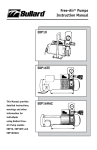
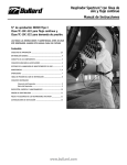
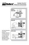
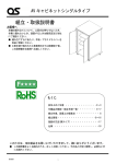
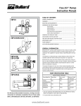
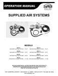
Free-Air® Pumps
User Manual
General Information
Bullard Free-Air Pumps transfer ambient air from a clean air location,
where breathable air can be assured at all times, to workers wearing
Type C or CE continuous flow supplied air respirator hoods or tight
fitting half- or full-face masks.
The ambient air is filtered through a medium efficiency inlet filter and
a CARBOFINE Outlet Filter before entering the respirator’s air supply
hose.
EDP30
Bullard Free-Air Pumps are oil-less and have rotary carbon vanes.
They produce no carbon monoxide, oil vapors, oil mist or moisture.
They do not require expensive carbon monoxide monitors, high
temperature alarms or airline filters. No calibration is required.
Read all instructions before using your Free-Air pump.
EDP50
Table of Contents
General Information.......................................................................1
Operating the Free-Air Pump .................................................. 6-7
Warnings.............................................................................................2
Maintaining the Free-Air Pump...................................................8
Number of Respirators that can be used with Pumps..........3
Trouble Shooting Guide.................................................................9
Brathing Air Requirements
Air Quality.............................................................................................4
Replacement Parts and Accessories.........................................10
Assembling the Free-Air Pump
Electric Motor Specifications ...............................................................5
Pump Performance Specifications .......................................................5
Warranty...........................................................................................11
Return Policy and Return Authorizations.............................. 11
Air Filter Replacement Schedule.............................................. 12
This manual provides detailed instructions, warnings and other information for individuals using Bullard Free-Air Pump
models EDP30 and EDP50
www.bullard.com
� WARNING
READ ALL INSTRUCTIONS IN THIS MANUAL BEFORE USING FREE-AIR® PUMP MODELS EDP30 OR EDP50.
FAILURE TO OPERATE THESE PUMPS IN ACCORDANCE WITH THE INSTRUCTIONS CONTAINED IN THIS MANUAL MAY RESULT IN DEATH OR
SERIOUS INJURY TO THE RESPIRATOR WEARER.
1. Place the pump’s inlet filters in a clean breathable air location at all times. The pump WILL NOT remove carbon monoxide, toxic gases or
other contaminants from the incoming air it transfers to the respirator wearer.
See the BREATHING AIR REQUIREMENTS section on page 4 for specific details on breathing air quality.
2. This pump will supply the required volume of air (6-15 cfm for hoods or 4-15 cfm for tight fitting mask) to low pressure supplied air
respirators. The respirators must be approved by MSHA/NIOSH to operate at 30 psig or less if using an EDP30 pump, or 15 psig or less if
using an EDP50 pump.
Be sure the pump’s outlet pressure, measured by the pressure gauge on the air supply hose’s quick-disconnect coupler pod, is maintained
above the minimum pressure setting required by the respirator manufacturer.
To verify your respirator can be used with this pump refer to:
a) The Pump Performance Table on page 3 for the maximum output air pressure (psig) of the pump model you are using.
b) The section in the respirator’s instruction manual for the MSHA/NIOSH approved pressure range and permissible air supply hose
lengths.
If you have any questions about whether or not your respirator is compatible with this pump, contact the respirator manufacturer or
Bullard’s Customer Service Department at 877-BULLARD or 1-859-234-6616.
3. Supplied air respirators used with this pump MUST NOT be worn in any atmosphere immediately dangerous to life or health or from which
the wearer cannot escape without the use of the respirator.
Supplied air respirators used with this pump MUST NOT be worn in oxygen deficient or unknown atmospheres.
4. When connecting respirators to the Free-Air pump, use only the air supply hose and couplers required by the respirator manufacturer and
approved by MSHA/NIOSH.
Use of non approved hoses or couplers will VOID the respirator’s MSHA/NIOSH approval and could reduce the air flow to the respirator,
resulting in possible death or serious injury to the respirator wearer.
5. DO NOT modify or alter the pump in any manner. Use only approved Bullard Free-Air pump components and replacement parts on this
pump.
Failure to use approved Bullard components and replacement parts invalidates all Bullard warranties, and may result in death or serious
injury to the respirator wearer.
6. If you have any questions concerning the use of the pump or your respirator, or you are not sure the inlet filters are in a breathable air
location, ask your supervisor.
All instructions for the use and care of this product must be supplied to you by your employer as recommended by the manufacturer and
as required by Federal Law (29 CFR 1910.134).
Warnings
For technical assistance or additional copies of this manual, call Bullard Customer Service or go to www.Bullard.com to download a copy.
2
Bullard
1898 Safety Way
Cynthiana, KY 41031-9303
Toll-free: 877-BULLARD (285-5273)
Phone: 859-234-6616
Web: www.bullard.com
Email: [email protected]
www.bullard.com
Free-Air® Pumps
User Manual
Number of Respirators that can be used
with Pumps
Maximum number of respirators at different air pressure
readings that can be used with EDP30 and EDP50 pumps
Depending on the pump model and style of respirator(s) being used,
Bullard EDP30 and EDP50 Free-Air Pumps will supply air for up to ten
(10) workers.
On the chart below, find the relevant Output Air Pressure (psig)
corresponding to the respirator’s approved pressure range to
determine the pump’s total air volume (cfm), and maximum number
of respirators that can be used at that air volume. For additional
information, the ampere loading on the pump’s motor is shown in the
right hand column.
Refer to the respirator’s MSHA/NIOSH approved pressure range and
permissible air supply hose length. The Respirator’s Minimum Approved
Pressure must be 30 psig or less if using Model EDP30 or 15 psig or
less if using Model EDP50.
Pump Performance Tables
EDP30 PUMP
Pump’s Output Air
Pressure (psig)
Pump’s Output Air
Volume (cfm)*
Maximum
Recommended Mask
Respirators**
Maximum
Recommended Hood
Respirators**
Motor Amp Load***
5
32
Six
Four
16
10
30
Six
Four
18
15
28
Five
Four
19
20
26
Five
Three
22
25
24
Four
Three
24
30
22
Four
Three
26
EDP30 PUMP WITH FRIGITRON 2000 AIR CONDITIONER
18-25
24-25
None
Two
17
EDP50 PUMP
Pump’s Output Air
Pressure (psig)
Pump’s Output Air
Volume (cfm)*
Maximum
Recommended Mask
Respirators**
Maximum
Recommended Hood
Respirators**
Motor Amp Load***
5
54
Ten
Seven
22
10
50
Ten
Seven
25
15
46
Nine
Six
28
** It should be noted that the Minimum Air Flow required for each tight-fitting mask style respirator is four (4) cfm and for
each hood style respirator is six (6) cfm.
The ratings which appear here, therefore, are conservative, but reflect Bullard’s position that worker respiratory
protection is enhanced when air flow available to the respirator wearer is above the NIOSH required minimums.
*** Motor Starter Overload Heater should not be exposed to more than 30 Amps of continuous electrical draw.
www.bullard.com
Pump Performance Tables
* Assumes that no air is being dumped from Pressure Relief Valves.
3
Breathing Air Requirements
Air Quality
The Free-Air® pump’s inlet filters MUST be located in a clean breathable air location at all times. Breathable air drawn into the inlet filters
MUST meet at least the requirements for Type 1 Gaseous Air described in the Compressed Gas Association Commodity Specification
G-7.1 (Grade D or higher), as specified by Federal Law 30 CFR, Part
11, Subpart J, 11.12(b).
The requirements of Grade D breathable air include:
* Carbon Monoxide........ 10 ppm maximum
* Carbon Dioxide...... 1,000 ppm maximum
* No toxic contaminants at levels which would make the air unsafe to breath.
Refer to the C.G.A. Commodity Specification G-7.1 for complete details.
It is available from:
Compressed Gas Association
500 Fifth Avenue
New York, NY 10036
Breathing Air Requirements/Assembling the Air Pump
Assembling the Free-Air Pump
4
The only assembly required on an EDP30 or EDP50 Pump is to attach
the air supply hose quick-disconnect pod(s) to the pump’s manifold.
1. Remove the pump from its shipping pallet and the air supply hose
quick-disconnect pod(s) from their shipping carton.
2. The air supply hose quick-disconnect pods can be located in the
work area, up to 300 feet from the pump. Use Bullard’s Cat. No.
V60, 100 foot extension hose to extend the pod(s): (If V60 extension
hose IS NOT required, go to instruction 3).
a) Attach the V60 extension
hose to the pump’s manifold.
If extending only one pod,
connect the V60 hose to the
manifold Kamlok coupler
that is not plugged. Lock the
Kamlok male fitting on the
hose to the Kamlok female
coupler on the manifold
(Figure 1).
b) If additional lengths of V60
extension hose are required, connect
them together using the Kamlok
couplers (Figure 2).
DO NOT EXTEND THE POD(S) MORE
THAN 300 FEET (3 LENGTHS OF
V60 HOSE) FROM THE PUMP’S
MANIFOLD.
* Oxygen.................................19.5 - 23.5%
* Hydrocarbons (condensed)
in mg/m3 of gas........ 5 mg/m3 maximum
NOTE
Due to the relatively high volume of air pumped through the V60
hose, the first 100 feet of hose may tend to vibrate. The vibration
dissipates as additional lengths of hose are added.
Figure 2
c) Attach the pod(s) to the end of the
V60 hose. They should be connected
so that the handle and pressure
relief valve are on top of the pod
(See Figure 3).
Lock the Kamlok Male Fitting on the
Pod to the Female Coupling on the
Hose.
Figure 3
3. If the V60 extension hose is not
required, assemble the pod(s) directly to
the pump’s manifold. The pods should
be connected so that the handle and
pressure relief valve are on top of the
pod (See Figure 4).
If using only one pod, connect it to the
Figure 4
manifold Kamlok coupler that is not
plugged. Lock the Kamlok male fitting
on the pod to the female coupler on the pump’s manifold.
Leave the plug in the other coupler to prevent air from freely flowing.
Figure 1
If you are not using the other manifold coupler, leave the Kamlok
plug installed to prevent air from freely flowing.
www.bullard.com
Free-Air® Pumps
User Manual
Electric Motor Specifications:
EDP30 and EDP50
Open, Drip-proof
ENCLOSURE:
Natl. Elec. Code:
Class B
Design L
Code K
CLASS:
H.P.
PHASE:
CYCLES:
Wiring:
Five
Single
60
208-230 volts as shipped, with 8 foot cord and three
wire, 30 amp plug (NEMA L6-30) and manual starter
F.L. Current
Draw:
24.0 Amps at 230 Volts,
25.5 Amps at 208 Volts
SERVICE FACTOR:
PROTECTOR:
1.15
Internal Thermal Overload in Motor Starter
� WARNING
Proper Wiring in accordance with local and national electric codes is
the responsibility of the user.
Pump Performance Specifications:
PUMP DESIGN:
MAXIMUM AIR PRESSURE:
AIR FLOW:
PRESSURE RELIEF VALVES:
PRESSURE GAUGES:
INLET FILTERS:
EDP30
EDP50
Rotary Carbon
Vane (4 vanes)
Rotary Carbon
Vane (4 vanes)
30 psig
15 psig
30 cfm at 10 psig
50 cfm at 10 psig
Adjustable, Pre-Set to open at 34 psig
when adjusted fully closed
Adjustable, Pre-Set to open at 15-17
psig when adjusted fully closed
Dry, 0-30 psig on Pod,
0-30 on Pump Manifold
Dry, 0-15 psig on Pods,
0-30 on Pump Manifold
Medium Efficiency, Paper-Type
Medium Efficiency, Paper-Type
CARBOFINE
CARBOFINE
TIRE PRESSURE:
50 psig Maximum
50 psig Maximum
26 Inches
38 Inches
32 Inches
292 Lbs.
26 Inches
38 Inches
32 Inches
292 Lbs.
DIMENSIONS:
Width:
Length:
Height:
WEIGHT:
www.bullard.com
Pump Performance
OUTLET FILTERS:
5
Operating the Free-Air® Pump
system being used, to the quickdisconnect coupler(s) or the
pod(s) (Figure 6).
� WARNING
The respirator wearer must NOT enter the contaminated work
area until all of the following steps have been completed.
1. Analyze the atmosphere at the location of the worksite, the air
inlet and the pump, to be sure the pump will not be operating in a
contaminated or an explosive atmosphere.
2. Make sure the pump’s inlet
filters are located in a clean,
uncontaminated location
where breathable air is
assured at all times (Figure 5).
The pump WILL NOT remove
carbon monoxide, toxic gases
or other contaminants from
the incoming air it transfers to
the respirator wearer.
Figure 5
3. Plug the pump into a single phase 230 or 208 volt electrical outlet.
The pump’s motor is equipped with an 8 foot cord with three wires,
30 amp plug (NEMA L6-30) and a manual starter.
You may use up to 50 feet of 30 amp,
three-wires grounded extension cord to reach your electrical outlet.
We recommend using 8 gauge wire. Avoid excessive lengths of
extension cord, especially if running the pump continuously.
� WARNING
Proper wiring in accordance with local and national electric codes
is the responsibility of the user.
Operating the Free-Air Pump
4. Assemble your respirator by following the manufacturer’s directions
as described in the respirator’s instruction manual.
6
Be sure the pump’s outlet pressure, measured by the pressure
gauge on the air supply hose attachment pod(s), will be greater
than the minimum MSHA/ NIOSH approved pressure required
to operate the respirator. The respirator’s minimum approved
pressure will be found in the respirator’s user manual and/ or on
labels attached to the respirator.
If you have any question as to whether or not your respirator is
compatible with the pump, call the respirator manufacturer or
Bullard’s Customer Service Department at 877-BULLARD or
1-859-234-6616.
5. While outside of the contaminated work area, connect the air
supply hose, that was approved by NIOSH as part of the respirator
NOTE
If your respirator’s air supply
hose, approved by NIOSH
as part of the respirator
system being used, will not
connect to the pod’s standard
1/2” Industrial Interchange
couplers, you can convert
the couplers to 3/8” female
NPT with installation of the
following adaptors.
Cat. No. V23 - Converts one
1/2” Industrial Interchange
coupler to 3/8” female NPT. One
V23 adaptor is required for each
coupler (Figure 7).
A variety of quick-disconnect
couplers or fittings may be used
to connect your air supply hose to
the 3/8” outlet adaptor. Contact
your respirator manufacturer for
the proper fitting (Hansen, Parker,
Snap-Tite, Schrader, Foster, etc.)
(Figure 8).
Figure 6
Figure 7
Figure 8
6. Before connecting your respirator to the air supply hose, turn the
pump on. Allow the air to flow through the pump and hose for a few
minutes to purge or expel any hose odors or moisture that may
have accumulated inside the hose.
7. While outside of the contaminated work area, connect the respirator(s)
to the air supply hose(s) using the quick-disconnect fittings.
8. With the air flowing, put on the respirator by following the
directions in your respirator manufacturer’s instruction manual.
9. Set the pump’s outlet pressure, measured by the pressure gauge
on the pod, to within the respirator’s approved pressure range.
See the respirator’s instruction manual for the approved pressure
range.
The pump has three pressure adjustment locations:
- Pressure relief valve on the pod(s)
- Pressure relief valve on the manifold
- Dump valve on manifold
www.bullard.com
Free-Air® Pumps
User Manual
Pressure Gauges
a) Close the dump valve
by turning the red knob
clockwise until no air can
escape (Figure 9).
NOTE
The dump valve provides a
course pressure adjustment
and may have to be used if
the respirator’s approved Figure 9
pressure is below 10 psig.
If so, you will also have to simultaneously use the pressure relief
valve on the pod(s) to obtain the exact pressure required.
b) Close the pressure relief valve on the pump’s manifold. Loosen
the lock nut on the relief valve and adjust the flow control knob
downward (clock wise) until no air can bleed off at the manifold
(Figure 10).
The pump has two pressure gauge locations (depending on pump model):
- One on the pump’s manifold
- One on each pod
The pressure gauge located on the pod(s) must be used as the gauge
to monitor the outlet pressure supplied to the respirators.
NOTE
If the pod(s) are attached directly to the pump manifold, the pressure gauges should always read within +/- 5% of each other. If the gauge on the manifold reads substantially higher
than the gauge on the pod, the outlet filter cartridges may be
clogged resulting in restricted air flow to the respirators.
If this occurs, we recommend the outlet filter cartridges be
replaced. See the maintenance section on page 8 for information on replacing the outlet filter cartridges.
If the pod(s) are attached to the end of the V60 extension hose, the
pressure difference between the manifold and pod(s) will be approximately 1 psig per 100 feet of V60 hose.
11. YOU ARE NOW READY TO ENTER THE WORK AREA.
Figure 10
If you are locating the pod(s) in a remote location from the pump
see instruction 2 in Assembling The Free-Air Pump section on
page 4. Make sure they are placed in an area away from other
equipment or machinery.
Figure 11
c) Use the pressure relief valve located on the pod(s) to set the
pump’s outlet pressure. The relief valve can be adjusted by
loosening the lock nut and adjusting the flow control knob until
the desired outlet pressure has been obtained. Retighten the
lock nut firmly to maintain a consistent flow (Figure 11).
The pressure on the gauge at the air supply hose pod must
be monitored regularly to assure it is maintained within the
respirator’s approved pressure range.
a) Close the relief valve on the pod(s) by adjusting flow control
knobs and retightening the lock nut(s) to prevent air from
bleeding at the pod(s).
b) Adjust the flow control knob on the manifold until the desired
outlet pressure has been obtained and retighten the lock nut
firmly to maintain a consistent flow.
c) Even if you use the manifold relief valve to adjust the outlet
pressure, the pressure must still be monitored at the pressure gauge on the pod(s) to assure it is maintained within the
respirator’s approved pressure range.
12. When finished working, leave the work area wearing the
respirator and with the air still flowing. Once outside the
contaminated area, remove the respirator, then disconnect the air
supply hose from the respirator’s quick-disconnect coupler.
See your respirator manufacturer’s instruction manual for proper
Inspection, Maintenance and Storage procedures.
Frigitron 2000 Cool Tube
Bullard’s FRIGITRON 2000 cool tube can be used in conjunction with
certain MSHA/NIOSH approved Bullard hood style respirators when
using the EDP30 Free-Air Pump.
The FRIGITRON 2000 and EDP30 pump will supply two (2) people
working in hot or humid areas with a continuous flow of cool air. The
cool tube will cool the incoming air into the respirator hood approximately 20-22 degrees below the ambient air temperature.
Pump Model EDP50 cannot be used to supply air to a respirator with
the Frigitron 2000 because it does not produce enough outlet pressure to drive the cool tube.
For complete information on specifications and performance of the
FRIGITRON 2000 refer to the Bullard respirator product literature and
instructions.
www.bullard.com
Operating the Free-Air Pump
10. If the flow of air dumped from the relief valve on the pod(s)
creates a problem in the work area, use the relief valve on the
manifold as the pressure adjustment valve.
The pod(s) must be protected from any equipment that could run
over, bump or damage it and cause a cut off of air flow to the
respirators.
7
Maintaining the Free-Air® Pump
Bullard EDP30 and EDP50 Free-Air Pumps consist of an electricallydriven air pump with four carbon vanes. The vanes self-adjust as they
wear and should last the following length of time if properly maintained:
EDP30 - 3,000 to 10,000 Hours
EDP50 - 1,500 to 5,000 Hours
For the pump to operate at its optimum performance level, the following
simple maintenance procedures must be performed routinely:
Replace the Inlet and Outlet Filters Regularly
Dirty or clogged filters will restrict air flow to the respirators by causing a
decrease in the pump’s outlet pressure. They may also decrease vane life
and cause eventual pump overheating.
• Replace the inlet filter (Cat. No. 23611) at least once every 500 running
hours or once per month, whichever is sooner.
Maintaining the Free-Air Pump
The Inlet Filter keeps particulates larger than 25 microns out of the
air supply and helps protect the pump’s carbon vanes.– Replace the
CARBOFINE outlet filter cartridges (Cat. No. S17101) at least once every
200 running hours or once per month, whichever is sooner.
8
The following are directions for replacing the outlet filter cartridge. These
steps must be performed outside the
contaminated work area:
a) Turn the pump off and disconnect
it from the power source.
b) Disconnect the air supply hose
attachment pod from the pump
or the V60 extension hose by
releasing the Kamlok clamps.
c) Remove the eight (8) wing nuts Figure 12
(with a wrench or pliers) and
bolts holding the quick-disconnect coupler manifold to the pod
(Figure 12).
d) Remove the filter cartridge plate
from the pod.
e) Unscrew the wing nuts and remove the caps holding the outlet
filter cartridges in their seats.
Figure 13
Remove and discard the used
filter cartridges (Figure 13).
f) Visually inspect the rubber
gaskets on the filter cartridge
plate for wear, cracks or tears
(Figure 14).
If any sign of damage is
detected, replace with a new
gasket (Bullard Cat. Nos. 26701,
filter side or 27161, cover side).
gasket onto the pod making sure the bolt holes are lined up with the
gasket.
g) Insert four (4) new filter cartridges in the seats and reassemble the
caps and wing nuts to hold the cartridges in place.
h) Reassemble the pod. Tighten the wing nuts and bolts together firmly
with a wrench or pliers, so that no air can escape between the three
parts.
i) Mount the pod back onto the pump or V60 extension hose, locking the
Kamlok clamps so that no air can escape.
j) Plug the pump back into its power source.
Flush the Pump if Necessary
Should excessive dirt, sand, foreign particles, moisture or oil be permitted
to enter the pump, the carbon vanes may become sluggish and the pump’s
performance will deteriorate. This will result in decreased outlet pressure or failure of the pump to operate.If the pump remains idle in a humid
environment for a long period of time, rust film may build up in the pump’s
chamber and/or rotor slots. This will result in decreased outlet pressure or
a failure to operate at all. If the above occurs, the pump should be flushed
with one of the following recommended safety solvents:
• Loctite Safety Solvent (Cat. No. S1791)
• Inhibisol Safety Solvent
• Dow Chemical Chlorothane
� WARNING
Never use kerosene or other combustible liquids or vapors with this pump.
Their use may result in an explosion which may cause injury or death.
Directions for Flushing Pump:
1. Before flushing, disassemble and remove the following parts from the
pump:
• Disconnect the respirator(s) air supply hose from the pod(s).
• Remove the pod or the V60 extension hose from the pump’s manifold.
• Remove the pump’s inlet filters.
2. With the pump running, pour several ounces of approved safety solvent
into each of the pump’s air inlet ports. Repeat the flushing if necessary.
� WARNING
Run the pump for a sufficient time to purge all traces of the safety
solvent before reconnecting the pods, inlet filters and air supply
hoses and using the respirators.
Avoid Running the Pump at Excessive Pressure
Avoid running the pump model EDP30 above 30 psig or the EDP50 above
15 psig for any length of time. Running the pumps above the maximum
recommended psig rating could cause motor damage and premature wear
of the carbon vanes.
NEVER LUBRICATE THIS OIL-LESS AIR PUMP. THE MOTOR BEARINGS
ARE GREASE PACKED AND SEALED. THEY REQUIRE NO FURTHER
LUBRICATION.
Figure 14
The old gasket will have to be scraped off the plate. Glue a new
www.bullard.com
Free-Air® Pumps
User Manual
Troubleshooting Guide
If your Bullard Free-Air pump is not working satisfactorily, follow the
Trouble Shooting steps below:
SYMPTOM: Pump Fails to Start or Hums
1. Turn pump switch off and disconnect from the power source.
2. Check for the correct electrical current as shown in the Electric
Motor Specifications on page 5 of this Manual.
3. Check to be sure that the circuit is not overloaded by the pump and
other electrical equipment. The pump is equipped with a thermal
overload protector that turns the current off when subjected to
electrical overloads.
4. Wait 15 minutes and restart.
SYMPTOM: Outlet Air Pressure Too Low
1. Be sure you know the proper pressure range for the respirator. See
the respirator’s instruction manual.
2. Be sure the respirator and air supply hose are connected to the
pump when the gauge reading is taken.
3. Check to see that the pressure gauges are functioning properly.
Replace the gauge(s) if broken or malfunctioning.
4. Check that both the inlet filters (Cat. No. 23611) and outlet filter
cartridges (Cat. No. S17101) are clean. Replace if necessary. Dirty
filters will restrict air flow.
5. Check to see that no air is escaping from the pressure relief valves
on the manifold and air supply hose pod(s). Reset the relief valves
if necessary.
6. Check to see that the air supply hose pod Kamlok couplers are
closed tightly so that no air can escape.
7. Flush the pump with Loctite Safety Solvent (Cat. No. S17931) to
remove excessive dirt, sand, particles, moisture or oil in the rotor
assembly. See the Maintenance section on page 8 for proper
directions on flushing the pump.
When the parts are reassembled, attach the respirator(s) and turn
the pump on, monitoring the outlet pressure.
SYMPTOM: Outlet Pressure Too High
2. Check the respirator’s air supply hose for kinks.
SYMPTOM: Pump Overheating
1. The normal output air temperature when the pump is running
continuously is 160-120 degrees. The heat is dissipated as it
travels through the respirator’s air supply hose until it reaches
ambient air temperature.
3. Check to see that the inlet filters (Cat. No. 23611) and the outlet
filters (Cat. No. S17101) are clean and replace if necessary. Dirty
filters will restrict air flow and cause overheating.
4. Flush the pump with Loctite Safety Solvent (Cat. No. S17931) to
remove excessive dirt, sand, particles, moisture or oil in the rotor
assembly.
See the maintenance section on page 8 for proper directions on
flushing the pump. When the parts are reassembled, attach the
respirators and turn the pump on, monitoring its performance for
overheating.
5. The electrical circuit to which the pump is connected is overloaded. Check the amperage load of the circuit and disconnect other elec
trical equipment, if necessary, from the circuit.
SYMPTOM: Outlet Air Temperature Too Warm
1. Be sure that at least the first 50 feet of air supply hose closest to
the pump is laid out (not coiled) to permit excess heat to dissipate
from the hose.
2. If using an EDP30 and Bullard supplied air respirator hoods, order
the FRIGITRON 2000 Air Conditioner. Two hoods with FRIGITRON
Air Conditioners can be used with model EDP30. Frigitron 2000
cannot be used with model EDP50.
3. Put a coiled section of the air supply hose in the bottom of a large
container. Fill the container with water and ice and cover with a lid. For
best results, locate the container as close to the worker as possible.
SYMPTOM: Outlet Air Temperature Too Cold
1. Let the pump warm up for approximately 15 minutes before using.
2. Coil the first 25-50 feet of air supply hose closest to the pump.
3. Keep the air supply hose off cold surfaces.
SYMPTOM: Moisture In Air Supply Hose Line
1. Locate the air inlet filter in a dry, clean air location, where
breathable air can be assured at all times.
2. With the air supply hose connected to the pump, but not the respirator, turn the pump on and let it run for approximately 15 minutes
to purge the hose of excessive moisture.
IF THESE STEPS FAIL TO RESOLVE THE PROBLEM,
CONTACT YOUR BULLARD DISTRIBUTOR OR BULLARD’S
CUSTOMER SERVICE DEPARTMENT AT 877-BULLARD
OR 1-859-234-6616.
www.bullard.com
Troubleshooting
1. If pressure relief valve(s) are set too high, reset to a lower pressure.
Be sure the outlet pressure remains in the approved range for the
respirator as specified by the respirator manufacturer. See your
respirator manufacturer’s instruction manual.
2. If pressure relief valves are set too high, reset to a lower pressure.
Be sure the outlet pressure remains in the approved range for the
respirator as specified by the respirator manufacturer. See your
respirator manufacturer’s instruction manual.
9
Replacement Parts and Accessories
Replacement Parts List
Optional Accessory Items
FOR BOTH EDP30 AND EDP50 FREE-AIR® PUMPS
Description
Cat. No.
Description
23611
26701
27161
28151
28152
S16481
S17101
S19681
S19683
S19688
S2084
S2085
S2089
S2090
Inlet Filter
Gasket, Pod, Filter Side
Gasket, Pod, Cover Side
Pressure Relief Valve EDP30
Pressure Relief Valve EDP50
Quick-Disconnect Coupler,1/2”
Industrial Interchange
Outlet Filter Cartridge
Pressure Gauge, 0-15 psig
Pressure Gauge, 0-30 psig
Pressure Gauge, 0-60 psig
Drive Belt, Matched Pair, EDP30
Drive Belt, Matched Pair, EDP50
Kamlok Adapter, Male, Pod
Kamlok Coupler, Female, Manifold
26781
26782
V23
V60
Remote pod, EDP30 (Includes six quick-disconnect
couplers, pressure gauge, pressure relief valve and outlet filter cartridges)
Remote pod, EDP50, same as above
Outlet Coupler Adaptor, converts 1/2”
Industrial Interchange
Coupler to 3/8” Female NPT
100 Foot 1 1/4” I.D. Pod
Extension Hose
Replacement Parts
Cat. No.
10
www.bullard.com
Free-Air® Pumps
User Manual
Return Policy
Return Authorization
EDP30 and EDP50 model Free-Air Pumps are built to the unique
customer specifications at the time of order and therefore are not returnable for credit. Please keep this in mind when placing your order
for one of these products, paying particular attention to the requested
motor size and electrical requirements, along with your respirator air
supply hose fitting compatibility.
Pump Warranty
TO RETURN GOODS: Written permission must be obtained before
returning any material for any reason. Material returned for credit
will be subjected to factory inspection. In warranty product of current
design will be subjected to a rehandling charge less freight originally
allowed. All material must be shipped with transportation charges
prepaid. Bullard will issue a Return Material Authorization number and
shipping label which must be affixed to all returns to facilitate handling
and reduce risk of loss. Products which are obsolete or made to special
order are not returnable. Warranty information can be obtained from
and defective articles should be sent and, shipping charges prepaid to:
Bullard
1898 Safety Way
Cynthiana, KY 41031-9303
Toll-free: 877-BULLARD (285-5273)
Phone: 859-234-6616
Web: www.bullard.com
Email: [email protected]
1. Contact Bullard Customer Service by telephone or email at:
Bullard
1898 Safety Way
Cynthiana, KY 41031-9303
Toll-free: 877-BULLARD (285-5273)
Phone: 859-234-6616
Web: www.bullard.com
Email: [email protected]
In your correspondence or conversation with Customer Service, describe the problem as completely as possible. For your convenience,
your Customer Service Representative will try to help you correct the
problem over the phone.
2. Verify with Customer Service that the product should
be returned to Bullard. Customer Service will provide
you with written permission and a return authorization
number as well as the labels you will need to return the
product.
3. Before returning the product, decontaminate and clean
it to remove any hazardous materials which may have
settled on the product during use. Laws and/or regulations prohibit the shipment of hazardous or contaminated
materials. Products suspected to be contaminated will be
professionally discarded at the customer’s expense.
4. Ship returned products, including those under warranty,
with all transportation charges pre-paid. Bullard cannot
accept returned goods on a freight collect basis.
5. Returned products will be inspected upon return to the
Bullard facility. Your Customer Service Representative
will call you with a quote for required repair work which
is not covered by warranty. If the cost of repairs exceeds
stated quote by more that 20%, Customer Service will call
you for authorization to complete repairs. After repairs
are completed and the goods have been returned to you,
Bullard will invoice you for work performed.
www.bullard.com
Pump Warranty/ Return Authorization
FREE-AIR PUMP ONE YEAR LIMITED WARRANTY
Bullard warrants to the original purchaser that the Free-Air Pump
will be free of defects in material and workmanship under normal use
and service for a period of one (1) year from the date of purchase.
Bullard’s obligation under this warranty is limited to repairing or
replacing, at its option, articles that are returned within the warranty
period and that are, after examination, shown to Bullard’s satisfaction
to be defective, subject to the following limitations.
a) Free-Air Pump must be returned to the Bullard factory with shipping charges prepaid.
b) Free-Air Pump must not be altered from its original factory configuration.
c) Free-Air Pump must not have been misused, subjected to negligent
use, or damaged in transport
d) The date of purchase is within the one year warranty period. (A
copy of the purchaser’s original invoice showing the date of purchase is required to validate warranty coverage)
In no event shall Bullard be responsible for damages for loss of use
or other indirect, incidental, consequential or special costs, expenses
or damages incurred by the purchaser, notwithstanding that Bullard
has been advised of the possibility of such damages.
ANY IMPLIED WARRANTIES, INCLUDING WARRANTIES OF
MERCHANTABILITY AND FITNESS FOR A PARTICULAR PURPOSE,
ARE LIMITED IN DURATION TO ONE (1) YEAR FROM THE DATE OF
PURCHASE OF THIS PRODUCT.
Some states do not allow the exclusion or limitation of incidental or
consequential damages, or allow limitations on how long an implied
warranty lasts, so the above limitations or exclusion may not apply to
you. This warranty gives you specific legal rights and you may have
other rights which vary from state to state.
IMPORTANT: THE FOLLOWING STEPS MUST BE COMPLETED
BEFORE BULLARD WILL ACCEPT ANY RETURNED GOODS.
PLEASE READ CAREFULLY.
Follow the steps outlined below to return goods to Bullard for repair
or replacement under warranty or for paid repairs:
11
Filter Replacement Schedule
Regular inspection and replacement of the air filters will prevent
extensive and costly pump repair. Dirty or clogged filters can be
responsible for failure of the pump to build up outlet pressure and
eventual overheating.
• Replace the CARBOFINE outlet filter (Cat. No. S17101) at least
once every 200 running hours or once per month, whichever is
sooner.
• Replace the medium efficiency inlet filter (Cat. No. 23611) at
least once every 500 running hours or once per month, whichever is sooner.
The inlet filter keeps moisture as well as particulates out of the
air supply and helps protect the pump’s carbon vanes.
We recommend the following chart be used to monitor and maintain a
routine air filter replacement schedule.
The outlet filter cartridge is multi-layered with 40-micron size
particles of activated carbon, a sorbent bed with an exposed
carbon surface of more than 15,000 square feet.
• Vapor removal efficiency: 90-95%
• D.O.P. efficiency: (0.3 to 0.6 micron particles) 99.97%
• Solid particle filtering: 0.3 micron and larger
• Liquid particle filtering: 0.75 micron and larger
CARBOFINE OUTLET FILTER
(Cat. No. S17101)
Cumulative
Pump
Operating
Hours
Last Filter
Replacement
Date
Employee
Responsible
(Initial)
200
400
600
800
1,000
1,200
1,400
1,600
1,800
2,000
Americas:
Bullard
1898 Safety Way
Cynthiana, KY 41031-9303 • USA
Toll-free within USA: 877-BULLARD (285-5273)
Tel: +1-859-234-6616
Fax: +1-859-234-8987
MEDIUM EFFICIENCY INLET FILTER
(Cat. No. 23611)
Cumulative
Pump
Operating
Hours
Last Filter
Replacement
Date
Employee
Responsible
(Initial)
500
1,000
1,500
2,000
2,500
3,000
3,500
4,000
4,500
5,000
Europe:
Bullard GmbH
Lilienthalstrasse 12
53424 Remagen • Germany
Tel: +49-2642 999980
Fax: +49-2642 9999829
Asia-Pacific:
Bullard Asia Pacific Pte. Ltd.
LHK Building
701, Sims Drive, #04-03
Singapore 387383
Tel: +65-6745-0556
Fax: +65-6745-5176
www.bullard.com
ISO 9001
certified
©2014 Bullard. All rights reserved.
Free-Air is a registered trademark of Bullard.
6095000710C (1214)