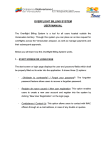
1
High Speed PTZ Camera
User Manual
English Edition
User manual
Menu
1 Foreword ...................................................................................................................................................................... 3
2 Product overview ...................................................................................................................................................... 1
2.1 Product brief descriptions .................................................................................................................. 1
2.2 Performance characteristics ................................................................................................................ 1
2.3 Function explanation .............................................................................................................................. 2
2.4 Technical patameters ................................................................................................................................ 4
3 Installation .............................................................................................................................................................. 4
3.1 Speed dome DIP switch settings .............................................................................................................. 4
3.1.1 Enter DIP switch settings ............................................................................................................ 5
3.1.2 DIP switch settings ........................................................................................................................ 5
3.2 Speed dome installation ............................................................................................................................ 7
3.2.1 Speed dome accessories ........................................................................................................................... 8
4 Speed dome basic opration ....................................................................................................................................9
5 Menu settings................................................................................................................................................................. 2
5.1 Main menu ...................................................................................................................................................... 2
5.2 System information......................................................................................................................................... 3
5.3 Address settings ................................................................................................................................................ 4
5.4 Motion ............................................................................................................................................................ 4
5.4.1 Set frame scan ................................................................................................................................... 5
5.5 Pattern ..................................................................................................................................................... 5
5.5.1 Program pattern .................................................................................................................................. 6
5.6 Camera setup memu ................................................................................................................................ 7
5.7 Cruise menu .................................................................................................................................................... 7
5.8 Display setup ................................................................................................................................................ 7
5.9 Restore factory default ............................................................................................................................ 8
5.9.1 Reboot system ............................................................................................................................................ 8
6 Simple fault clearing and maintain ..........................................................................................................8
6.1 Simple fault clearing form ...................................................................................................................... 8
6.2 Notice .............................................................................................................................................................. 8
6.3 After service ................................................................................................................................................8
User manual
1
Foreword
Before install and use high speed PTZ camera,please read below information carefully,
1.Before installation please read user manual carefully.
2.Please do not test and install the product on unstable flat,make sure the product place on a stable flat
and assembly firmly before operation.
3. Prevent products damage caused by stress, severe vibration and immersion on transportation and
storage.
4. Installation of this product must not be reversed;please handle with care,do not squeeze structural
components, Otherwise, they may cause mechanical failure, affecting the overall performance.The
transparent material on the speed dome iris is advanced optical materials,do not touch it,any scratches will
affect image quality.
5. Prevent any foreign matter or liquid into camera,to avoid damage on camera.
6. When you make connection,please follow up safety standards,use with a dedicated power supply.
RS-485 and video signal adopt TVS grade lightening protection technique,can effectively prevent damage
caused by not more than 500W lighting,surging and other types of pulse signals.Please keep enough
distance away from High-voltage equipment or cables when RS-485and video signal during
transmission.Make lighting and surging protection measures when necessary.
7. Whether in use or non-use, never allow cameras aimed at the sun or other bright objects。Otherwise,
may result in permanent damage of CCD .
8.Do not use it exceed the temperature, humidity standards.
9. This product do not have user repair parts。When camera has fault,please do not repairit,should find
out fault refer to user manual,if can not find out reason,please send the camera to professional
maintanence person. The maintenance person must be authorized by our company.
2 Product overview
2.1 Product brief description
High speed PTZ camera adopt the latest scientific and technological achievements,best manufacturing
technique,successful developed by years of valued experience,it is a high-performance digital signal
processing (DSP) camera which equips with automatic zoom lens;build-in PTZ and digital decoders,
representing a new generation of high-tech monitoring products. It uses all-digital control, simple and
ingenious design, discretional quickly locate and continuous follow-up scan,it has automatic tracking
function,make smart surverillance of all-round, non-blind spot,Can automatically adapt to the environment
and target distance changes in light and dark, High reliability and long-term stable operation, without
maintenance.
High speed PTZ camera is compatible with a variety of control protocols,so it can support a variety of
popular platforms.Match with other system,the connection use methods of different system is not the
same,please contact the system manufacturer or distributors for necessary information.
The various characteristics of the high speed PTZ camera , make it applicable to large-scale industries,
active target object surveillance。Such as power systems, telecommunications sector, banking security,
factories and enterprises, intelligent buildings, intelligent community, urban road monitoring, airports,
stations and other monitoring occasions.
2.2 Performance characteristics
1. Build-in OSD English menu ,through menu to display and change the information and parameter of
camera,can set and incoke presets、pattern scan、area scan and display areaetc.
2. Timing auto- activation function, Can set the ball machine idle for a period of time,then startarea scan,
intermittent scan,continuous scan,pattern scan and invoke presets.
3. Integrated design, compact structure , high reliability.
4. 256 presets.
5. Adopt RS485 control.
6. Precision motor drive, running smoothly and responsive.
7. Horizontal 360°continuous rotation, no surveillance blind area.
8. Rotation speed automatic adjust according to lens’ zoom.
9. Veritial 90°,auto overturn 180°continuous surveillance.
10. Auto focus,auto white balance
11. Backlight compensation,you can see all the objects in a strong light enviroment.
User manual
12. Compatible with a variety of control protocol, baud rate adjustable.
13. Wide Dynamic Camera Support(SONY1010、SONY490、SONY990)
2.3 Function explanation
Below is a brief introduction of high speed PTZ camera main function,chievement and operation
principles of each function, does not involve a specific method of operation.
1.Setup address code,baud rate,contron protocol
Any operation commands has camera address code,baud rate and control protocol, any single
camera only respond to its own address code, baud rate, control protocol command.The detailed setup
ways of camera address code,baud rate and control protocol please refer to DIP switch settings.
2.Tacking
User can use the keyboard joystick to control the camera turning up,down,left or right, Can be used
to track moving targets or moving horizon,in addition you can change the eyeshot size and image size by
adjusting the focal length. In the auto-focus state, with the lens rotation, the camera will automatically
quickly adjust according to scenery change, instantly get a clear picture.
3.Focal length / rotation speed automatic matching technique
Manual adjustment,in long focal length situation,high speed reflect makes image quickly move when
a slight touch of joystick,resulting a data loss.Based on a humanized design,the PTZ camera can
automaticly adjust horizontal and vertical rotation speed according to focal length ,so that manual operation
is simple and easy to track targets.
4.Auto overturn
The operator pull the lens to bottom (vertical) and still hold the joystick,lens auto horizontal overturn
180°then downward overturn 90°,direct see the back of scenery,achive vertical 180°full continuous
monitoring.
5.Setup and invoke presets
Preset function means speed dome can store horizontal and tilt angle of platform as well as camera lens
focal length and other parameters in memory,you can quickly invoke these parameters and adjust platform
and camera to the location.User can easily and quickly control equipment to storage and invoke preset via
keyboard and IP controller,this high speed PTZ has 256 presets.
6.Lens control
1)Focal length control
User can adjust the focal length via keyboard and matrix,in order to receive the necessary panoramic
images ormicro-lens image.
2)Focus control
System default auto-focus, zoom,camera lens will automaticly focus to the centre of scene,keep image
clear; In exceptional circumstances the user can manually focus to achieve the desired image effect.
When in manual focus state, sway the control bar to restore the auto-focus,.There is also a
dedicated control commands or invoke a preset to restore auto focus.
The camera lens in the following situations will not auto focus:
User manual
a.The object does not in the centre of image;
b.The object in the near and far place at the same time;
c.The object is bright objects,such as neon lighting, spotlights;
d.The object is behind glass which with droplets or dust;
e.The object is moving too fast;
f.Large area object,such as wall;
g.Objectives are too dark or inherently dim.
7.Aperture control
User can manual adjust aperture size via keyboard inorder to obtain the required image brightness.
8.Auto backlight compensate
When the backlight compensation function is open,camera lens in the light background can make auto
brightness compesation to dark objective.Make adjustment to bright background,avoid a mass of
brightness and object can not identifiable because of darkness.
9.Auto white balance
According to the changes in ambient light, automatic adjustment, reproduct true color .
10.Night vision function(B/W switch)
Camera with night vision function,at B/W mode,it will automaticly switch CCD illumination according to
enviroment light changes.For example,in the day,the light is adequate,use general illumination keep
images colorful.At night it will auto change to low illumination,display scene clear in black and white image.
11.Auto cruise
Pre-set cruise presets,arrange some presets to cruise queue in order,only a command can make
indoor intermediate speed dome constant movement in specified time interval according to presets order.
12.Pattern scan
Pattern scan means store the speed dome move track,then invoke the scan track via power-up action,
free movement, alarm linkage.
13.Continous scan
Only a command or invoke via power-up action, free movement, alarm linkage,make speed dome
continuous loop scan at a certain speed in horizontal.
14. Intermittent scan
Only a command or invoke via power-up action, free movement, alarm linkage,make speed dome
intermittent loop scan at a certain speed in horizontal.
15. Frame scan
Only a command or invoke via power-up action, free movement, alarm linkage,make speed dome
reginal loop scan at a certain speed in horizontal.
16. Wide Dynamic
Support SONY newsest FCB-EC490,FCB-EC990,FCB-EC1010 wide dynamic camera, applied in
strong backlighting environments.
User manual
2.4 Technical parameter
Model
SD-CeR29-30
Imaging source
1/4 ″CCD
System
PAL/NTSC
Resolution
Color 480TVL,B/W 600TVL
Effective pixel
752(H)ⅹ582(V)
Min. illumination
Color to B/W,color 0.05Lux,B/W 0.001Lux
S/N ratio
≥60dB
Backlight
compesation
ON/OFF
White balance
AUTO
Electronic
shutter
1/50~1/12000 second
Focal length
3.0~90mm
Optical zoom
30x
Focus
Auto/manual , adopt high-performance DSP,achieve all-digital
continuous focus function
Presets
256
Pattern scan
4 channels,each channel can record 100 action
Cruise track
30 presets can join cruise,preset stay time can set
Other scan
Support horizontal scan,frame scan,radom scan
Rotation range
Horizontal 360°unlimited,vertical 180°,auto overturn
Rotation speed
Horizontal and vertical:min. 0.01°,max. 300°/s(can auto adjust
according to zoom times)
Protocol
PELCO D and PELCO P
Menu
Full screen menu
Temperature
control system
Optional
Power supply
AC 24V
Dimension
6 inch
Operation
condition
Material
-10 ℃~ +70℃ ( Optional temperature control components ),
﹤95%RH
Aluminum shell, waterproof ratingIP66
3 Installation
3.1 Speed dome DIP switch settings
High speed dome camera is compatible with a variety of control protocols, baud rate can be adjusted
to make it compatible with more monitoring and control system 。 Before install the speed dome
camera,please adjust the DIP switch to appropriate code according to your requirements,in order to adjust
User manual
the baud rate,control protocol,address code. If there are no special requirements,the speed dome factory
default address code is 1,baud rate is 2400BPS corresponding code,control protocol is PELCO-D
corresponding code.
3.1.1 Enter DIP switch settings
Through DIP switch to change BAUD-RATE,PROTOCOL and ADDRESS.Speed dome core, housing
and DIP switch pictures see future 1,
Future 1.Dome core and DIP switch
3.1.2 DIP switch settings
SW1:Baud rate and control protocol switch
SW2:Address code switch
DIP switch “ON” means “1”,DIP switch “OFF”means“0”, DIP switch left is low position ,right
is high position
Baud rate and control protocol setting form:
SW1
Code
point
Control
protocol
Baud
rate
1
2
3
4
OFF
OFF
PELCO-P
ON
OFF
PELCO-D
OFF
ON
Reservation
ON
ON
Reservation
OFF
OFF
AUTO
ON
OFF
2400
OFF
ON
4800
ON
ON
9600
2. SW2 is used for setting speed dome address code。Address adopt binary mode,you can set at total 256
different speed dome address code, see address code table. The factory default settings shown in Figure
2.
User manual
Address
SW2 speed dome address code table
1
2
3
4
5
6
7
8
0
OFF
OFF
OFF
OFF
OFF
OFF
OFF
OFF
1
ON
OFF
OFF
OFF
OFF
OFF
OFF
OFF
2
OFF
ON
OFF
OFF
OFF
OFF
OFF
OFF
3
ON
ON
OFF
OFF
OFF
OFF
OFF
OFF
4
OFF
OFF
ON
OFF
OFF
OFF
OFF
OFF
5
ON
OFF
ON
OFF
OFF
OFF
OFF
OFF
6
OFF
ON
ON
OFF
OFF
OFF
OFF
OFF
7
ON
ON
ON
OFF
OFF
OFF
OFF
OFF
8
OFF
OFF
OFF
ON
OFF
OFF
OFF
OFF
9
ON
OFF
OFF
ON
OFF
OFF
OFF
OFF
10
OFF
ON
OFF
ON
OFF
OFF
OFF
OFF
11
ON
ON
OFF
ON
OFF
OFF
OFF
OFF
12
OFF
OFF
ON
ON
OFF
OFF
OFF
OFF
13
ON
OFF
ON
ON
OFF
OFF
OFF
OFF
14
OFF
ON
ON
ON
OFF
OFF
OFF
OFF
15
ON
ON
ON
ON
OFF
OFF
OFF
OFF
16
OFF
OFF
OFF
OFF
ON
OFF
OFF
OFF
17
18
ON
OFF
OFF
ON
OFF
OFF
OFF
OFF
ON
ON
OFF
OFF
OFF
OFF
OFF
OFF
19
ON
ON
OFF
OFF
ON
OFF
OFF
OFF
20
OFF
OFF
ON
OFF
ON
OFF
OFF
OFF
21
ON
OFF
ON
OFF
ON
OFF
OFF
OFF
22
OFF
ON
ON
OFF
ON
OFF
OFF
OFF
23
ON
ON
ON
OFF
ON
OFF
OFF
OFF
24
OFF
OFF
OFF
ON
ON
OFF
OFF
OFF
25
ON
OFF
OFF
ON
ON
OFF
OFF
OFF
26
OFF
ON
OFF
ON
ON
OFF
OFF
OFF
27
ON
ON
OFF
ON
ON
OFF
OFF
OFF
28
OFF
OFF
ON
ON
ON
OFF
OFF
OFF
246
OFF
ON
ON
OFF
ON
ON
ON
ON
247
ON
ON
ON
OFF
ON
ON
ON
ON
248
OFF
OFF
OFF
ON
ON
ON
ON
ON
249
ON
OFF
OFF
ON
ON
ON
ON
ON
250
OFF
ON
OFF
ON
ON
ON
ON
ON
251
ON
ON
OFF
ON
ON
ON
ON
ON
252
OFF
OFF
ON
ON
ON
ON
ON
ON
253
ON
OFF
ON
ON
ON
ON
ON
ON
254
OFF
ON
ON
ON
ON
ON
ON
ON
255
ON
ON
ON
ON
ON
ON
ON
ON
User manual
3.2 Speed dome camera installation
Future 1: After glass cover removal
Future 2: Remove the foam and ready to remove platform to see DIP Switch
Future 3:There are 2 lines of DIP switch under platform,8 bits is address code switch,4 bits is protocol
and baud rate switch.
Future 4:fix wall mounting brackets, then use a pen to draw the location of the four screw holes。
User manual
Future 5 Make cable through wall mounting brackets。
Future 6Integration of the ball machine and wall bracket
3.2.1 Speed dome install accessories dimension
4
The basic operation of the speed dome camera
Since different platforms of concrete operation methods are not identical, Generally, should be based
on the system manufacturer's operating manual prevail under different circumstances will have special
requirements and methods of the operation, please contact the dealer to obtain the necessary
information.Here only Introduced the keyboard how to control the ball machine method.
1.Power On Self Test
After the speed dome camera power on, the camera process the horizontal and vertical movement by
auto, Through the self-test to determine speed dome camera work fine.
Control the camera rotation from top to bottom ,right to left:
After selected one camera, you can manually control the speed dome camera top to bottom,right to left by
the joystick .The joystick control the movement of the camera, when the joystick shake to the right, the
camera is also to right. Similarly, when the joystick to the left , camera same too.
2. Preset setting
According to the following steps to set preset :
(1) select the camera (more information please read control of the keyboard manual);
(2) operation joystick, zoom button, focus button, buttons adjust the camera aperture screen;
(3) Press the number key +PRESET (Enter the specified preset ), save the preset scene parameters.
3. Call preset
Follow the below step to watch the preset:
(1)select the camera;
(2) Press the number key +PREVIEW (enter the designated preset ), the camera move to the preset
position immediately, the lens zoom, focus and aperture is also automatically change to the preset
parameters; if the input is a special function of the preset (see "Preset function menu"), the speed dome
camera will perform with special features preset of the corresponding functions (such as: Enter the 80
preset, the camera auto-tracking feature).
Preset function list
Special
preset
Specific of function
INVOKE NO 95
Enter main menu
INVOKE NO XXX
Call preset
INVOKE NO 82
Auto cruise
INVOKE NO 83
Clear all preset
INVOKE NO 84
Call 1 pattern scan
INVOKE NO 85
Call 2 pattern scan
INVOKE NO 86
Call 3 pattern scan
INVOKE NO 87
Call 4 pattern scan
INVOKE NO 96
360 scan
INVOKE NO 97
Call the region between two scanning
INVOKE NO 98
Preset cruise
INVOKE NO 99
360 continuous scan
4.Close-up lens and wide-angle lens
xxx.
User manual
Zoom adjustment, or to narrow the disparity between the camera lens, zoom in or out the scenery to
get close-up and wide-angle effect. Hold down the ZOOM+ , the camera features are closer to the picture
of the object is magnified; hold the ZOOM- , the camera features pulled away, the screen object has been
reduced. If you press and quickly release the zoom button, the camera monitor screen only for small
changes. The camera zoom changes depends on the length of time holding down the zoom button.
5.Lens Focus Control
Focus is adjustable camera images of an object or scene in the clarity of the process. Hold down the
FOCUS+ from the distant objects or scenes clear up near objects become blurred. Hold down the FOCUS-,
proximity to clear up objects or scenes, distant objects become blurred. Focus button repeatedly until you
adjust the monitor screen objects into clear from the ambiguity. The same as the zoom button, the camera
focused vary depending on the length of time holding down the focus button.
6.Manual Iris Function
The camera aperture to change the brightness of the screen. Hold down the IRIS+ , the camera picture
change to light, hold down the IRIS- , the camera screen change to dimmed. The same as the zoom button,
the camera light dark vary depending on the length of time holding down the aperture button.
5 Menu settings
This chapter will introduce the operation of OSD menu.Plug in power,after speed dome self-test,you
will see below information:
Control protocol:PELCO-D
SATA information:2400,N,8,1
Speed dome address:1
The information will always display beforethe operation.
Different surveillance systems has different operation ways,detailed operation please contact
distributor.Here below is an easy introduction of NQJ302 control keyboard(our company product)to
operate OSD menu.
1.Enter main menu:setup No.95 preset,and you will enter OSD main menu.IRIS+(iris open)is the
confirm key,IRIS-(iris close)is the exit key.
2.Enter other menu:Up / down shake the joystick, so that the cursor is pointing to a menu,press
IRIS+enter the menu.
3.Function select:Up / down shake the joystick, so that the cursor is pointing to a menu,press
IRIS+select this function.
4.Parameter select:Up / down shake the joystick to select the parameter,press IRIS+,then restore.
5.Restore settings:Press IRIS+ ,restore the settings,it is effective if has corresponding prompt.
6.Does not restore and back to last menu: press IRIS- back to last menu, it is effective if has
corresponding prompt.
7.Exit menu: Up / down shake the joystick,so that the cursor is pointing to exit option,press IRIS+exit
OSD menu.
8.Back to previous menu:so that the cursor is pointing to back option,press IRIS+ and back to previous
menu.
Notes:Different speed dome setting,different display on speed dome.
The following is detailed description of use smart standard control keyboard to oprate OSD menu:
5.1 Main menu
Speed dome work normally,set No.95 preset,enter main menu,screen display is as Future 3.1.
User manual
MAINMENU
<SYSTEM INFORMATION>
<ADDR SETTING>
<MOTION>
<PATTERNS>
<CAMERA>
<CRUISE SETTING>
<DISPLAY SETUP>
<RESTORE FACTORY DEFAULT>
<REBOOT SYSTEM>
<EXIT>
Future 3.1 MAIN MENU
Main menu contents despription:
<SYSTEM INFORMATION>:show basic information of speed dome
<ADDR SETTING>:set speed dome soft address
<MOTION>:function parameter setting
<PATTERNS>:pattern scan setting
<CAMERA>:lens setting
<CRUISE SETTING>:presets cruise setting
<DISPLAY SETUP>:character display switch
<RESTORE FACTORY DEFAULT>:restart lens,resume default parameter,resume factory default
setting.
<REBOOT SYSTEM>:restart system.
<EXIT>:exit OSD menu
To enter the menu and the implementation of the various functions of the basic operation is as
follows:
1.On Future 3.1 MAIN MENU,Up / down shake the joystick, so that the cursor is pointing to a menu
item or function option;
2.Press IRIS+ ,enter menu or operate a function option.
5.2 <SYSTEM INFORMATION>
In the Future 3.1 MAIN MENU, swithching the rocker with up/down, turn the cursor to <SYSTEM
INFORMATION>, then press IRIS+, enter into system menu.
SYSTEM INFORMATION
COM
2400,N,8,1
ADDRESS
1
PROTOCOL
PELCO-D
PRESETS
256
SOFTWARE VERSION
V5.2
BACK
EXIT
Future 3.2 SYSTEM INFORMATION
SYSTEM INFORMATION: checking the basic information of the speed dome camera. Followings are
the functions:
COM:SATA information, present the information of Baudrate, Check bit, Data bit, Stop bit for the
current speed dome camera.
ADDRESS:the address of speed dome camera, show the address coding of the current speed dome
camera range from 0 to 255.
PROTOCOL:protocal, show the communication protocal of the current speed dome camera.
User manual
SOFTWARE VERSION:show the current software version.
BACK:return to the main menu
EXIT:exit the main menu.
remark:revising the sysytem menu is not allowed under the current menu
5.3 <ADDR SETTING>
In the future 3.1 MAINMENU, swithching the rocker with up/down, turn the cursor to <ADDR
SETTING>, then press IRIS+, enter into picture future 3.3 ADDR SETTING to set the address.
ADDR SETTING
ADDR TYPE
HARD
ADDR SOFT
3
BACK
EXIT
Future 3.3 ADDR SETTING
In 3.3 ADDR SETTING, swithching the rocker in the keyboard with up/down, HARD and SOFT are
selectable within the ADDR TYPE value, after the installation of system, we can remote setup the address of
speed dome camera on opening SOFT address.
ADDR HARD:set the hard address for speed dome camera via DIP switch.
ADDR SOFT:direct control software address to realise remote control via keyboard.
5.4 <MOTION>(platform setting)
In the future 3.1MAINMENU, swithching the rocker with up/down, turn the cursor to <MOTTON>, then
press IRIS+, enter into <MOTTON> menu.
MOTION
<SET FRAME SCAN>
POWER UP
NONE
PARK TIME
15S
PARK ACTION
NONE
FRAME SCAN SPEED
16
BACK
EXIT
Future 3.4<MOTION>
<MOTION> to set the parameters such as PTZ motion and degree of azimuth.
<SET FRAME SCAN>:to set the scanning area
POWER UP:power setting, to set the operation of speed dome camera within the time between
finished powering and receiving order. The following are the parameter introduction:
NONE:perform no action.
CRUISE: perform the action of preset crusing
AUTO SCAN: perform the action of continious scanning
RANDOM SCAN: perform the action of intermittent scanning
FRAME SCAN :perform the action of frame scanning(taking effect after setting)
PRESET 1: reach the first preset
PRESET 8: reach the first preset
PATTERN 1: perform pattern scanning at Circuit 1
PATTERN 2: perform pattern scanning at Circuit 2
User manual
PATTERN 3: perform pattern scanning at Circuit 3
PATTERN 4: perform pattern scanning at Circuit 4
PARK TIME:the time setting for performing Parking Actions
Parameter Range:15s,1minute,2mintues…59mintues,1hour…12hours。
PARK ACTION:exit the menu of speed dome camera, in the park time, performing the action without
receiving any order.
The parameter introduction for PARK ACTION.
NONE: perform no action
( restore the latesting action):auto restore the latesting action.
CRUISE:perform the action of preset scanning(taking effect after setting)。
AUTO SCAN:perform the action of continious scanning
RANDOM SCAN:perform the action of intermittent scanning
FRAME SCAN:perform the action of frame scanning(taking effect after setting)。
PRESET 1:reach the first preset。
PRESET 8:reach the first preset。
PATTERN 1:perform pattern scanning at Circuit 1.
PATTERN 2:perform pattern scanning at Circuit 2.
PATTERN 3:perform pattern scanning at Circuit 3.
PATTERN 4:perform pattern scanning at Circuit 4.
FRAME SCAN SPEED :set the speed for frame scanning, parameter range 1~32。
BACK:return to main menu.
EXIT: exit the menu setting.
The basic operation for the setting of functional parameter..
1.In the picture of 3.4<MOTION> menu,switch the rocker in the keyboard with up/down, enable the
cursor point to some option in the menu.
2.Press the key of IRIS+;
3.switch the rocker in the keyboard to select the parameter you expected.
4.Then press the key of IRIS+。
5.4.1<SET FRAME SCAN>
SET FRAME SCAN, the specific opeartion are:
In the 3.4MAINMENU, swithching the rocker with up/down, turn the cursor to < SET FRAME SCAN >,
then press IRIS+, enter into the following picture:
FRAME SCAN
SET SCAN POSITION
CLEAR FRAME SCAN
BACK
EXIT
Future 3.4.1 FRAME SCAN
<SET FRAME SCAN> to set the range of frame scanning。
<SET SCAN POSITION>:setting the range of frame scanning
<CLEAR FRAME SCAN>:cancelling the range of frame scanning
BACK:return to the previous menu.
EXIT:exit the menu
User manual
5.5<PATTERN>
In the picture of 3.1 MAINMENU,switch the rocker in the keyboard,make the cursor to <PATTERN>,
then press the key of IRIS+,enter into 3.5 Pattern scanning menu.
PATTERNS
PATTERN NUMBER
1
<PROGRAM PATTERN>
CLEAR CURRENT PATTERN
CLEAR ALL PATTERN
BACK
EXIT
Future 3.5<PATTERN> menu
Pattern Scanning is to set and clear scanning circuit.
Pattern Scanning Numbers:select the scanning number from 1 to 4。The specific opeartion:
1.In the picture 3.5<PATTERN> MENU,switch the rocker in the keyboard to make the cursor point to
PATTERN NUMBER,
2.Press the key of IRIS+;
3.switch the rocker in the keyboard to select pattern scanning number.
4.Press the key of IRIS+。
5.5.1<PROGRAM PATTERN>
< PROGRAM PATTERN >is to set program pattern
1.select the scanning number
2.In the picture 3.5<PATTERN> MENU,switch the rocker in the keyboard to make the cursor point to
<PROGRAM PATTERN>;
3.Press the key of IRIS+,enter into the following picture:
PROGRAM PATTERN
USE THE JOYSTICK OR
KEYBOARD TO MOVE THE
CAMERA
TO
THE
STARTING POSITION
IRIS OPEN TO CONTINUE
Future 3.5.1PROGRAM PATTERN
4. switching the rocker in the keyboard to fix the initial position,
5.press the key of IRIS+,enter into the following picture:
PATTERN
STORAGE USED
1
Future 3.5.1.1PATTERN
6.Switching the rocker,editing the initial position and operation,from the first motion to the utmost 100
motions,press the key of IRIS+,save the setting,return to 3.5;
User manual
5.6 CAMERA(lens)set the menu
5.7 CRUISE(the setting of preset crusing)menu
The image 3.1MAINMENU main menu, up / down shake the joystick, so that the cursor point
<CRUISE>, then hold down IRIS+ to enter map 3.7CRUISE preset points cruise,setting menu.
CRUISE
DWELL TIME [SECS]
6
PRESET LIST
1
1 ON
0 OFF
1234567890
PRESET
1111111111
[1-10]
BACK
EXIT
Future 3.7: CRUISE setting menu
Preset point cruise is used to automatically set the camera preset point of scan lines. To do the
following::
1.The image 3.7 <CRUISE> (preset point cruise settings) menu, up / down shake the joystick, so that
the cursor point to DWELL TIME [SECS] (preset cruise waiting time between points), Hold down IRIS+,up /
down shake the joystick, select the waiting time, Hold down IRIS+
2. Then, up / down shake the joystick, the cursor points to PRESET LIST (preset cruise list), Hold down
IRIS+ , up / down shake the joystick, choose to participate in preset cruise page, total of 30 preset points can
be participate in cruise, each page can select 10 preset points, total 33 pages, the corresponding
parameters 1,2,3,press IRIS+ to confirm.
3. Then, up / down shake the joystick, so that the cursor points to PRESET LIST (pre-cruise-point list),
according to IRIS + button, up / down shake the joystick, choose to participate in pre-cruise-point page,
total of 30 preset points can be participate in cruise, each page can select 10 preset points, total 3 page,
the corresponding parameters for the 1,2,3,press RIS+ to confirm
Then, up / down shake the joystick so the cursor point to 1234567890
111111 1111,Left / right shake the joystick,
choose to participate in the pre-cruise point, the corresponding parameters for the 0,1 press IRIS+ to
change.1 is choice, 0 is skipped.
5.Shake up / down joystick, select the BACK / EXIT, to save the setting, return
5.8 DISPLAY SETUP(Character DISPLAY SETUP):
DISPLAY SETUP:character display switch ON / OFF
ON:display ON means open
OFF:display OFF means close
User manual
5.9 RESTORE FACTORY DEFAULT:
RESTORE FACTORY DEFAULTS
WAIT
6.0 REBOOT SYSTEM:
6
6.1
Easy troubleshooting and maintenance
Easy troubleshooting list
Error reports
No movement after
power on,no image
Self test and with
image after power
on but can not
control
The image unstable
Problem
Solution
connect the wrong power
cable
Correct
Power supply is damaged
Replacement
Protective tube is damaged
Replacement
Power cable connect not
good
Eliminate
the ball machine address
coding, control protocol,
baud rate is wrong
re-set the ball machine address coding,
control protocol, baud rate
RS-485
wrong
cable
connect
Video cable connect not
good
Power is not enough
Can control but not
Check RS-485 connect cable
Eliminate
Replacement
RS-485 cable connect not
good
Check RS-485 connect cable
One of the RS-485 cable
broken
Check RS-485 connect cable
6.2 Notes
1. Careful Transport
Transport, storage and installation process, we need to prevent stress, severe vibration and damage to the
product immersion.
User manual
2. Do not demolish unauthorized Camera
Do not remove screws or protective cover, there is no repair parts machine. The work should by qualified
maintenance people to do it.
3. Be careful installation of the movement
To be especially careful, light up-light down, do not force squeezing movement and the structural
components, so as to avoid the ball machine trouble. For security reason, do not cover the ball is not
installed electricity.
4. Power, video lines and control lines
Power lines, video lines and control lines preferable to use shielded cable and is independent of routing,
can not blend together with other lines.
5. Electrical Safety
In use must comply with all electrical safety standards, the ball machine or signal transmission line should
work with high-voltage equipment or cables to maintain a sufficient distance (at least 50 meters), if
necessary, do a good job against lightning, surge and other protective measures.
6. Cleaning
When cleaning the camera housing, please use the dry soft cloth. such as severe dirt, please use neutral
cleaner gently wipe. Do not use strong or with abrasive cleaner, so as not to scratch jacket, affecting image
quality.
7. Please strictly sealed to prevent liquid splashing into the ball machine, otherwise it will result in
permanent damage to the device.
8. Do not use the camera when exceed the limits of temperature, humidity.
Ball machine use temperature of -25 to 70 , humidity less than 90%.
9. Do not install the camera near the air-conditioned outlet.
Under such conditions, the lens would be fogging following the state of hydrometeor
By the opening and closing air-conditioner frequently caused the high and low temperature changed.
By the opening and closing door frequently caused the high and low temperature changed.
Make the glasses fogging environment.
In a room filled with smoke or dust .
Do not use the camera toward strong light for long time, such as the sun..
Spotlight and other light will cause screen aging. Use the camera toward to strong light for a long time, may
be rised CCD of the color filter damage and loss the ture color images.
6.3 Service
Dear users, in order to ensure the full enjoyment of your services, please read the following products and
services charter.
(一) Protruly company supply the speed dome camera of limited warranty and lifetime maintenance
services
1. The warranty period from the date of sale for 12 months, in the warranty period, you will enjoy the
product free service, delivered or sent by the user (improper use,man-made causes of failure or an
irresistible fault do not belong to the scope of the warranty).
2. After 12 month limited free repairing duration,the products will absorb life time repair with payable
services.。
User manual
(二) Speed dome camera repair time.
1.Since the customer send the product to the Protruly, 24-hour service.
1. 2. Please advise the related contact first, then return the product to our company. Otherwise, the
product not timely maintenance