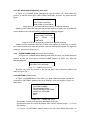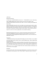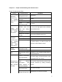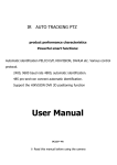
1
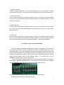
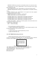
IR
AUTO TRACKING PTZ
product performance characteristics
Powerful smart functions:
Automatic identification PELCO D/P, HIKVISION, DAHUA
etc. Various control protocol.
2400, 9600 baud rate 4800, automatic identification.
485 pro-and-con connect automatic identification.
Support the HIKVSION DVR 3D positioning function
User Manual
DC 12V/AC24V---3A
※ Read this manual before using the camera
safety announcements
1.Careful transportation
Transport, storage and installation process, we need to prevent stress, severe vibration
and damage to the product immersion.
2. Be careful installation of dome camera modules
To be especially careful, light up-light down, do not force squeezing movement and the
structural components, so as to avoid the dome camera trouble. For security reason, do
not cover the housing is not installed electricity.
3. Power, video cables and control cables
Power cables, video cables and control cables preferable to use shielded cable and is
independent of routing, can not blend together with other cables.
4. Electrical Safety
In use must comply with all electrical safety standards, the ball machine or signal
transmission line should work with high-voltage equipment or cables to maintain a
sufficient distance (at least 50 meters), if necessary, do a good job against lightning, surge
and other safeguard procedures.
5. Cleaning
When cleaning the camera housing, please use the dry soft cloth. such as severe dirt,
please use neutral cleaner gently wipe. Do not use strong or with abrasive cleaner, so as
not to scratch jacket, affecting image quality.
6. Please strictly sealed to prevent liquid splashing into the ball machine, otherwise
it will result in permanent damage to the device.
7. Do not use the camera when exceed the limits of temperature, humidity. Dome
camera use temperature of -25 ℃ to 70 ℃, humidity less than 90%.
8. Do not install the camera near the air-conditioned outlet.
Under such conditions, the lens would be fogging following the state of hydrometer.
By the opening and closing air-conditioner frequently caused the high and low
temperature changed.
By the opening and closing door frequently caused the high and low temperature
changed.
1
Make the glasses fogging environment.
In a room filled with smoke or dust .
9. Do not use the camera toward strong light for long time, such as the sun..
Spotlight and other light will cause screen aging. Use the camera toward to strong light for
a long time, may be raised CCD of the color filter damage and loss the true color images.
Catalogue
catalogue............................................................................................................................ 2
Chapter 1 Product summarize ........................................................................................... 2
1.1 product synopsis ............................................................................................................ 2
1.2 technical parameters ..................................................................................................... 3
1.3 function explain .............................................................................................................. 4
Chapter 2 equipments’ installation .................................................................................. 6
2.1 camera’s dial-up and switch setting ............................................................................ 6
Chapter 3 Menu setting and operate ................................................................................ 8
3.1 Basic operation .............................................................................................................. 8
3.2 System OSD menu operate........................................................................................... 9
3.2.1 main menu............................................................................................................ 10
3.2.2 menu’s operation .................................................................................................. 10
3.2.3 <SYSTEM INFORMATION> ................................................................................ 11
3.2.4 <ADDR SETTING> .............................................................................................. 11
3.2.5 <MOTION> .......................................................................................................... 12
3.2.6 <SET FRAME SCAN> ............................................................................................ 13
3.2.7 CLEAR FRAME SCAN......................................................................................... 14
3.2.8 PATTERN ............................................................................................................. 14
3.2.9 PROGRAM PATTERN ......................................................................................... 15
3.2.10 CAMERA ......................................................................................................................... 16
Chapter 4 simple error and maintain............................................................................. 20
4.1 simple error exclude form .......................................................................................... 20
4.2 After Service ............................................................................................................. 21
2
Chapter One Product Summarize
1.2 Technical Parameters
Model Number
Auto Tracking speed dome
Image sensor
1/4" CCD 1/3"CCD
Signal mode
PAL/NTSC
Horizontal
resolution
480TVL/540TVL/650TVL
Effective pixel
PAL:976(H) x 582(V)
Minimum
illumination
Color to B/W,Color 0.05LUX,B/W 0.001LUX
S/N ratio
>60dB(Enhanced)
Backligh
compensation
ON/OFF
White balance
Auto
Electronic
shutter
1/50~1/12000s
Focus length
3.2~115.2mm
Optical focus
22xX27/X/30X/36X/360X
Focus
manual/Auto , take high-performance DSP to realize complete
digital and ulta-high speed focus function
IR distance
IR 150M
Presets
256
Patrol Track
4groups,each can record 100 actions
Cruise track
30 presets can join cruise, can setting the presets’ residence time.
Other scan
Support Horizontal scan, deuce area scan, scan random
Rotation Range
Horizontal 360°unlimted rotation,Vertical 180°,auto reversal
Rotation speed
Horizontal&Vertical Min 0.01° Max 200°/s.
Communications
PELCO-D and PELCO-P
OSD
Full screen menu
Temperature
Control
Optional
Power supply
DC12V/AC24V
Dimension
7 inch
Material
Aluminum shell, waterproof IP66
Wrok
Environment
-25℃~+70℃(select temperature control accessories)
,﹤95%RH
NTSC:976(H) x 494(V)
3
1.3 Function Description
IR 7-inch brief intelligent high speed dome camera integration, the main function
1. Set address coding, baud rate, control protocol
Any operation commands the camera has its own objectives address coding, baud rate,
control protocol, a single camera only to respond with its own address coding, baud rate,
control agreement under the operation of the command. Camera address coding, baud
rate, control protocol specific settings please refer to the dial-setting methods.
2. Tracking
Users can use the controls on the keyboard joystick control of the upper and lower turning
left and right cameras can be used to track moving targets or moving horizon, while the
focal length can be adjusted to change the perspective of the size or the target image size.
In the auto-focus of the state, with the lens rotation, the camera will automatically adjust
according to a rapid scene changes, instantly get a clear picture.
3. Focal length / speed automatic matching technique
Manual adjustment, the longer the focal length of the case, a reflection of high-speed
ball machine makes a slight touch screen joystick may move back, resulting in data loss.
Based on user-friendly design, intelligent ball according to the proximity of the focal length
of the camera automatically adjusts the horizontal and vertical speed, so that manual
operation is more simple and easy to track targets.
4. Auto MDIX
The operator will pull the bottom of the lens (vertical) after it is still holding down the
joystick, this time the level of the lens auto-rotated 180 ° turning up immediately after the
90 °, can directly watch the back of the scene in order to achieve the full 180 ° continuous
vertical surveillance.
5. Settings and call preset position
Preset function is the current state of the ball under the PTZ function of the horizontal
angle, tilt angle and camera lens focal length, etc. position parameters stored in memory,
you need to call these parameters can be quickly and PTZ cameras will be adjusted to
that location. The operator can quickly and easily by controlling the keyboard, infrared
controller, control equipment such as storage and call the preset point, the ball machine to
support 256 preset points.
6. Lens Control
(1) Zoom control
Users can control the keyboard or through the ball machine to adjust the focus of the
distance matrix of the host, receive the necessary panoramic images, or is a fine view.
(2) Focus Control
4
System default auto-focus, zoom, the camera lens will be the center of the screen
features auto-focus, to maintain a clear picture; in exceptional circumstances, the user
can manually focus, achieve the desired image effect.
When in manual focus state, to restore the auto-focus, as long as the sway bar can be
restored remotely auto-focus. There is also a dedicated control commands can be issued
or to call an arbitrary way of restoring a preset bit auto-focus.
The camera lens in the following situations will not autofocus on the camera objectives:
a. Target is not to screen center;
b. Targets the same time in the far and near the place;
c. Target light objects, such as neon lighting, spotlights and other luminous objects;
d. Target with droplets or dust behind the glass;
e. Targets moving too fast;
f. Large area targets, such as walls;
g. Objectives are too dark or inherently ambiguous.
7. Aperture Control
Users can control the keyboard, manually adjust the aperture size, to obtain the required
picture brightness.
8. Auto Backlight Compensation
When the backlight compensation function is open, the camera lens in the light
background can be automatically targets the more the dark luminance compensation. On
the bright background light adjustment, to avoid the background brightness caused by a
mass of light throughout the picture, goals and not identifiable because of the darkness to
gain a clear image.
9. Auto White Balance
According to the changes in ambient light, automatic adjustment, the true color
reproduction.
10. Night vision function (color / monochrome conversion)
Cameras with night vision function, automatic color / monochrome conversion mode, in
accordance with changes in ambient light automatic conversion CCD illumination. Such
as: adequate lighting during the day due to the use of general illumination to ensure
colorful images. In the night illumination can be automatically changed to black and white
images show a clear interest.
11. Cruise
Can be pre-set cruise preset point, certain preset points, organized in the order required to
auto-cruise in the queue, only an external command can be in an indoor speed ball set
automatically according to preset points in order to provide the time interval constant
movement back and forth.
5
12. Pattern scanning
Pattern scanning machines to run the ball through the menu, the trajectory is stored
down by power-on action, free movement, alarm linkage, etc. to call the stored scan line.
13. Continuous scan
Just an external command or through a power-on action, free movement, alarm linkage,
etc. to call, can make the ball machine horizontal direction to a certain speed the cycle of
continuous scanning.
14. Batch Scanning
Just an external command or through a power-on action, free movement, alarm linkage,
etc. to call, can make the horizontal direction the ball machine cycle of a certain speed
intermittent scan.
15. Area scan
Just an external command or through a power-on action, free movement, alarm linkage,
etc. to call, can make the ball machine horizontal direction to a certain speed, within the
limits set by the community and from scanning.Chapter 2 Equipment installaiton
2.1 Camera’s dial-up and Switch setting
IR7-inch integrated intelligent speed dome camera is compatible with a variety of
control protocols, baud rate can be adjusted to make it compatible with more of the
monitoring system. In the fixed installation of ball machine before, according to the need
to adjust the DIP switches to the appropriate coding, to change the baud rate of the ball
machine, control protocol, address coding. If there are no special requirements, the ball
machine factory default value for the address coding "1", the baud rate is set to
"2400BPS", Control Protocol is set to "PELCO-D".
IR 6-inch integrated intelligent speed dome camera can be DIP switch to change the
ball machine, "Baud Rate (BAUD-RATE)", "Control Protocol (PROTOCOL)" and "address
coding (ADDRESS)". Ball machine movement DIP switch plans, such as:
Note: 4 DIP switches as follows: baud rate and control protocol switch
8 DIP switches as follows: Address DIP Switch
6
DIP switch appropriated for "ON" means "1", DIP switch appropriated for "OFF" means "0",
DIP switch on the left for the low, right is high
Baud rate and control protocol setting form:
No.
1
2
Buad rate
(BPS
Control
protocol
3
4
ON
OFF
2400
OFF
ON
4800
ON
ON
9600
ON
OFF
PELCO-D
OFF
ON
PELCO-P
8-bit DIP switch is used to set the ball machine address coding. Address set binary
mode can be set to a total of 256 different ball machine address coding, see coding table
address.
Camera
address
Coding form
1
2
3
4
5
6
7
8
0
OFF
OFF
OFF
OFF OFF OFF OFF OFF
1
ON
OFF
OFF
OFF OFF OFF OFF OFF
2
OFF
ON
OFF
OFF OFF OFF OFF OFF
3
ON
ON
OFF
OFF OFF OFF OFF OFF
4
OFF
OFF
ON
OFF OFF OFF OFF OFF
5
ON
OFF
ON
OFF OFF OFF OFF OFF
6
OFF
ON
ON
OFF OFF OFF OFF OFF
7
ON
ON
ON
OFF OFF OFF OFF OFF
8
OFF
OFF
OFF
ON
OFF OFF OFF OFF
9
ON
OFF
OFF
ON
OFF OFF OFF OFF
10
OFF
ON
OFF
ON
OFF OFF OFF OFF
11
ON
ON
OFF
ON
OFF OFF OFF OFF
12
OFF
OFF
ON
ON
OFF OFF OFF OFF
246
OFF
ON
ON
OFF
ON
ON
ON
ON
247
ON
ON
ON
OFF
ON
ON
ON
ON
248
OFF
OFF
OFF
ON
ON
ON
ON
ON
249
ON
OFF
OFF
ON
ON
ON
ON
ON
250
OFF
ON
OFF
ON
ON
ON
ON
ON
251
ON
ON
OFF
ON
ON
ON
ON
ON
252
OFF
OFF
ON
ON
ON
ON
ON
ON
253
ON
OFF
ON
ON
ON
ON
ON
ON
254
OFF
ON
ON
ON
ON
ON
ON
ON
255
ON
ON
ON
ON
ON
ON
ON
ON
7
Chapter 3 Menu setting and Operate
3.1
Basic Operation
3.1.1 Power-On Self-Test
The ball machine power, the camera horizontal and vertical movement, the screen will
appear system-related information, such as dome-associated system message
disappears, the dome camera self-test to complete the following diagram
PTOL: AUTO
COMM:AUTO
ADDR: 1
Display:AUTO protocol、Buad Rate AUTO、Address code 1
3.1.2 control the camera rotating around the upper and lower
After selecting a camera, you can manually control the keyboard on the joystick up and
down around the dome camera movement. The shake control joystick moves the camera,
when the joystick to the right shake, the camera is also to right. Similarly, when the
joystick to the left when the camera shake movement is also to the left. Rocker vertical
shake when the camera also follows the appropriate action to do the vertical direction.
Shake the joystick according to the diagonal direction, it can allow the camera to do the
same time, horizontal and vertical movement, and direction of motion consistent with the
joystick.
3.1.3 Lens Focus Control
Note: Different manufacturers keyboard preset keys are different, the keyboard
manufacturer.
By controlling the keyboard on the "ZOOM-" and "ZOOM+" button to control the variable
lens multiples (ie, closer, pulling away).
By controlling the keyboard on "FOCUS-" and "FOCUS+" button to control the focusing
lens (camera must be set to "manual" focus or the "Auto / Manual" focus to be effective).
Note: The following situation may occur can not focus on the case
a: are looking at target is not to screen center.
b: At the same time observe the distant and near targets, not at the same time ensure that
front and rear are clear.
C: target for the light body, such as spotlights, car headlights and so on.
d: target is moving too quickly or the environment too dark.
Iris control of most of the camera for automatic Iris control, and if manual control over Iris,
through the keyboard on the "IRIS+" and "IRIS-" button to complete the Iris open and
closed
3.1.4 presets setting
8
Setting Presets:
(1) selected camera (see manual control of the keyboard);
(2) operation Rocker, zoom button, focus button, buttons adjust the camera aperture
screen;
(3) Press the number keys + PRESET (input designated preset) to preserve the scene
preset parameters.
Call preset points:
(1) Selected camera;
(2) Press the number keys (inputs the designated preset) + PREVIEW button, the
camera immediately move to the preset position, the lens zoom, focus and Iris is also
automatically change to the preset parameters; if the input is a special function preset
point (see "Preset Point menu"), the dome camera will perform with special features
preset point of the corresponding functions,
Presets Function form
Dial the 95th Presets
Enter Main menu
th
clear all presets
th
use Patrol scan 1
th
use Patrol scan 2
th
use Patrol scan 3
th
use Patrol scan 4
th
360-degree gap scan
th
scan between two presets
th
presets cruise
th
Auto Cruise
Dial the 83 Presets
Dial the 84 Presets
Dial the 85 Presets
Dial the 86 Presets
Dial the 87 Presets
Dial the 96 Presets
Dial the 97 Presets
Dial the 98 Presets
Dial the 99 Presets
3.2 System OSD menu operation
This section will detail the operation of OSD menu. Power is switched on, the dome
camera self-test after the monitor screen will display the following information:
Control Protocol: AUTO
Serial Information: AUTO
dome camera Address: 1
Since different control keyboard on the dome camera operation method are not
identical, specific operations, please contact the keyboard dealer.
1. To enter the main menu: Call 95 preset points, will enter the OSD main menu.
IRIS-(aperture opening) is to identify key, IRIS + (aperture closure) is a key to exit the
menu.
2. Into the other menu: up / down shake the joystick, so that the cursor is pointing to a
menu, press IRIS-key, to enter the menu.
3. Function options: up / down shake the joystick, so that the cursor is pointing to a
function key, according to IRIS-key, select the current function.
4. Parameters: up / down shake the joystick, select parameters, according to IRIS-key,
9
save the current parameters.
5. Save Settings: Press IRIS-key, save the current settings, when there is valid under the
appropriate prompt.
6. Exit menu: up / down shake the joystick, so that the cursor point to the menu "EXIT"
option, then IRIS + button to exit OSD menu.
7. To return to the previous one menu: up / down shake the joystick, so that the cursor
menu, point to "BACK" option, then IRIS-key, to return to the previous menu level.
Notes: 1. Settings for different ball machine, ball machine displays the contents of the
different power.
The following describes in detail the use of ball machine OSD menu operation.
3.2.1 Main Menu
Ball machine power and working properly, call the 95 preset points, into the main menu
screen display shown in Figure 3-1.
I
MAINMENU
<SYSTEM INFORMATION>
<ADDR SETTING>
<MOTION>
<PATTERNS>
<CAMERA>
<CRUISE SETTING >
<ALARMS SETTING >
<DISPLAY SETUP>
<IR SETTING>
RESTOE FACTORY DEFAULT
REBOOT SYSTEM
EXIT
lmage 3-1 MAINMENU
Description of the contents of the main menu:
<SYSTEM INFORMATION>:Display cameras’ basic informations
<ADDR SETTING>:Can setting soft dome’s address.
<MOTION>: Parameters setting.
<PATTERNS>: patrol scan setting
<CAMERA>:lens setting
<CRUISE SETTING >: presets cruise setting
<ALARMS SETTING >:alarm settings
<DISPLAY SETUP> :display setting
<IR SETTING>: ir setting
RESTORE FACTORY DEFAULT:Restart lens, recover parameters as default configration,
recover factory setting.
REBOOT SYSTEM: System restart, To re-power-on reset
EXIT:exit OSD MENU
3.2.2
Menus for execute functions basic operations
1. In Figure 3-1MAINMENU the main menu, up / down shake the joystick, so that the
cursor is pointing to a menu item or feature option;
10
2. Press IRIS-key, to enter the menu or perform a particular function
3.2.3 <SYSTEM INFORMATION> (System Information menu)
In Figure 3-1 MAINMENU the main menu, up / down shake the joystick, so that the
cursor point <SYSTEM INFORMATION>, then IRIS+ key, enter Figure 3-2 System
Information menu.
SYSTEM INFORMATION
COM
2400,N,8,1
ADDRESS
1
PROTOCOL
PELCO-D
PRESETS
256
SOFTWARE VERSION
V5.2
BACK
EXIT
Image 3-2 SYSTEM INFORMATIO system information menu
SYSTEM INFORMATION use for check camera’s current basic informations. It’s
functinon indtroduce as follow:
COM:Sata information,Display cameras current SATA BAUD Rate, Parity bit, data
bits,stopbits of information.
ADDRESS: Dome camera’s address, displays the current ball machine address
coding ,0-255.
PROTOCOL:Control protocol,Displays the current ball machine communication
protocol。
SOFTWARE VERSION:display current software version.
BACK:back to main menu.
EXIT: exit menu setting.
Note: The System Information menu, the various elements in this menu can not be
changed.
3.2.4 <ADDR SETTING> (Address Settings menu)
In Figure 3-1 MAINMENU the main menu, up / down shake the joystick, so that the
cursor point <ADDR SETTING>, then IRIS+ key, enter the Figure 3-3ADDR SETTING
address settings menu.
ADDR SETTING
ADDR TYPE
HARD
ADDR SOFT
3
ADDR HARD
1
BACK
EXIT
Image 3-3 ADDR SETTING address menu setting
In image 3-3 ADDR SETTING Address Settings menu, up / down shaking rocker, ADDR
TYPE (address type) value can select HARD (hard address) and SOFT (soft address) in
the system installation is complete, you can direct the remote Set ball machine address.
ADDR SOFT: In the ADDR TYPE selection SOFT, you can directly determine the ball
machine address.
11
Attention:
:soft address and hard address setting must not be confused, or the ball
machine out of control, everything is set to be effective needs to be restarted
3.2.5 <MOTION> (PTZ settings)
In Figure 3-1MAINMENU the main menu, up / down shake the joystick, so that the
cursor point <MOTION>, then IRIS+ key, enter Figure 3-4 <MOTION> menu.
MOTION
<SET FRAME SCAN>
POWER UP
PATTERN 4
PARK TIME
15S
PARK ACTION
PATTERN 4
FRAME SCAN SPEED
16
BACK
EXIT
Image 3-4<MOTION>
Menu clarification:
<MOTION> Menu is used to set PTZ parameters such as movement and orientation
angles.
<SET FRAME SCAN>:Is used to set the region to scan the left and right pole
POWER UP:On the power to set the menu, on the power to set the ball machine is used
to set the power, no control instructions received prior to the implementation of the action.
Parameters as follows:
NONE(no):Does not perform any action.
CRUISE(Preset Point cruise): implementation of the preset points, cruise movements.
AUTO SCAN(Continuous scan): implementation of a continuous scanning motion.
RANDOM SCAN(Intermittent scanning): the implementation of intermittent scanning
motion.
FRAME SCAN(Area scan): implementation of the regional scan action (regional
scanning range was set after the valid).
PRESET 1(Preset point 1): to reach No. 1 preset points.
PRESET 8(Preset point 8): reach the 8 preset points.
PATTERN 1(Pattern scan 1): implementation of the pattern scanning line 1
PATTERN 2(Pattern scan 2): implementation of the pattern scan line 2.
PATTERN 3 (pattern scan 3): implementation of the pattern scanning line 3.
PATTERN 4(Pattern scan 4): implementation of the pattern scan line 4.
PARK TIME:The time required for the implementation of free movement settings.
Parameter range of 15s, 1 minute, 2 minutes ... 59 minutes, 1 hour ... 12 hours.
PARK ACTION:Exit ball machine menu, in the idle time, the ball machine does not
receive any instruction of the implementation of the action.
Free action parameter description:
NONE(no):Does not perform any action.
12
REAPEAT LAST(Recovery last action): automatically restore to the most recent action.
CRUISE(Preset Point cruise): implementation of the pre-cruise-point action (preset
point is set after the valid).
AUTO SCAN(Continuous scan): implementation of a continuous scanning motion.
RANDOM SCAN(Intermittent scanning): the implementation of intermittent scanning
motion.
FRAME SCAN(Area scan): implementation of the regional scan action (regional
scanning range was set after the valid).
PRESET 1(Preset point 1): to reach No. 1 preset points.
PRESET 8(Preset point 8): reach the 8 preset points.
PATTERN 1(Pattern scan 1): implementation of the pattern scanning line 1.
PATTERN 2(Pattern scan 2): implementation of the pattern scan line 2.
PATTERN 3(Pattern scan 3): implementation of the pattern scanning line 3.
PATTERN 4(Pattern scan 4): implementation of the pattern scan line 4.
FRAME SCAN SPEED :Settings area scanning speed, set the ball machine area
scanning speed. Parameter range 1 ~ 32.
BACK:Return to Main Menu
EXIT: exit the menu setting
Function parameters to set the basic operations:
1.Image 3-4<MOTION>(PTZ settings) menu, up / down shake the joystick, so that
the cursor is pointing to the menu features an option;
2.Press IRIS+ key;
3.up/down Shaking rocker, select the parameters you need;
4.Again press Press IRIS+ key。
3.2.6 <SET FRAME SCAN>(setting area scan)
Settings area scanning range, specific operations are as follows:
In Figure 3-4 <MOTION> (PTZ settings) menu, up / down shake the joystick, so that the
cursor point <SET FRAME SCAN>; by IRIS+ key, enter the following diagram:
FRAME SCAN
SET SCAN POSITION
CLEAR FRAME SCAN
FRAME SCAN SPEED 1
BACK
EXIT
Image 3-4-1FRAME SCAN setting area scan
<SET FRAME SCAN> Menu is used to set the scope of the regional scan.
<SET SCAN POSITION>:Set the scope of the regional area scan
<CLEAR FRAME SCAN>:Clear area scan range
BACK: Back to a Menu
EXIT:exit the menu
13
3.2.7 SET SCAN POSITION(setting area scan )
In Figure 3-4-1 FRAME SCAN Settings area scan the menu, up / down shake the
joystick, so that the cursor point <SET SCAN POSITION>; by IRIS+ key, enter the next
figure
SET FFRAME SCAN
LEFT LIMIT POSITION
IRIS OPEN TO CONTINUE
Image igure 3-4-2 to set the left limit position of regional scanning
Shaking rocker, select the area scan the left limit position; by IRIS+ key, to confirm the
current position is the left limit position, and enter the following diagram:
SET FFRAME SCAN
RIGHT LIMIT POSITION
IRIS
OPEN
TO
CONTINUE
lmage 3-4-3 to set the right limit positions of regional scanning
Shaking rocker, choose the right limit of area scan position; by IRIS+ key, to confirm
the current position is the right limit position, save the extreme left position and right limit
positions, and return to Figure 3-4-1.
3.2.8
CLEAR FRAME SCAN (Clear area scan location)
In Figure 3-4-1 FRAME SCAN Settings area scan the menu, up / down shake the
joystick, so that the cursor point <CLEAR FRAME SCAN>; by IRIS+ key, enter the
following diagram:
CLEAR FFRAME SCAN
IRIS OPEN TO CONTINUE
lmage 3-5. CAMERA settings menu
By IRIS+ key, clear the position of the left and right limits of extreme position and
return to Figure 3-4-1.
3.2.9<PATTERN>(Pattern scan)
In Figure 3-4 MAINMENU the main menu, up / down shake the joystick, so that the
cursor point <PATTERN> (pattern scan), then IRIS-key, enter the pattern in Figure 3-5
Scan Menu
PATTERNS
PATTERN NUMBER
1
PROGRAM PATTERN
CLEAR CURRENT PATTERN
CLEAR ALL PATTERN
BACK
EXIT
lmage 3-5-1 Pattern scan menu
Scan pattern is used to set and clear the pattern scan lines.
Synchronized Scan ID: Select the pattern scan number. Number range 1 ~ 4. To do
the following:
1. In Figure 3-5 <PATTERN> (pattern scan) menu, up / down shake the joystick, so
14
that the cursor point PATTERN NUMBER (pattern scan) number;
2. Press IRIS+ key;
3. Up / down shake the joystick, select the pattern scan number;
4. Press IRIS+ key
3.2.10 <PROGRAM PATTERN> (pattern scan settings)
"Synchronized scan settings" is used to set the pattern scan lines. To do the following:
1. Select pattern scan number;
2. Pattern in Figure 3-5 Scanning the menu, up / down shake the joystick, so that the
cursor point <PROGRAM PATTERN>;
3. Press IRIS+ key, enter the following diagram:
PROGRAM PATTERN
MOVE THE CAMERA TO THE
STARTING POSITION
IRIS OPEN TO CONTINUE
lmage 3-5-2 PROGRAM PATTERN settings menu
4. Shake joystick to determine the starting position of the scan pattern;
5. By IRIS+ key, will enter the following diagram:
PATTERN
STORAGE USED<PCT>
1
lmage 3-5-3 PATTERN settings menu
6. Sway away from pole, edit, scan lines and movement, a movement began to record
from up to 100 moves, according to IRIS+ key, save the settings, return to Figure 3-5;
3.2.11 CAMERA (Lens) settings menu(
(Different lens with different parameters)
In Figure 3-1 the main menu, up / down shake the joystick, so that the cursor point
<CAMERA>, then IRIS+ key, enter the camera menu controls, enter the settings menu
Figure 3-6 CAMERA
Languages
Chinese/English
Multiples Display
ON/OFF
AGC
180
Blighlight
compensate
ON/OFF
Shutter setting
AUTO
Focus setting
AUTO
Brightness
setting
110
Sharpness
Setting
013
Day& night
switch
AUTO
Negative Set
OFF
Lens Set
OFF
Default Set
OFF
15
lmage 3-6CAMERA settings menu
Function parameters to set the basic operations:
1. The lens in Figure 3-6 to set menu, up / down shake the joystick, so that the cursor
is pointing to the menu options for a particular function;
2. Press IRIS+ key;
3. Up / down shake the joystick, select the parameters you need;
4. Then IRIS+ key.
3.2.12 CRUISE (preset points, cruise settings) menu
In Figure 3-1MAINMENU the main menu, up / down shake the joystick, so that the
cursor point <CRUISE>, then IRIS+ key, enter the preset point of Figure 3-7 CRUISE
cruise settings menu.
CRUISE SETTING
DWELL TIME <SECS>
6
PRESET LIST
1 ON
1
0 OFF
1234567890 <PRESET1-10>
1111111111
BACK
EXIT
lmage 3-7CRUISE preset point setting menu
Preset point cruise is used to automatically set the camera preset point of scan lines. To
do the following:
1. In Figure 3-7 <CRUISE> (preset points, cruise settings) menu, up / down shake the
joystick, so that the cursor point to DWELL TIME [SECS] (pre-cruise waiting time between
points), according to IRIS+ key, on the up / down shaking rocker, select the waiting time,
according to IRIS+ key.
2. Then, up / down shake the joystick, so that the cursor points to PRESET LIST
(pre-cruise-point list), according to IRIS+ key, up / down shake the joystick, choose to
participate in pre-cruise-point page, a total of 30 presets can be point involved in cruise,
each page you can select 10 preset points, a total of 33 pages, the corresponding
parameters 1,2,3, according to IRIS+ button to confirm.
3. Then, up / down shake the joystick, so that the cursor points to PRESET LIST
(pre-cruise-point list), according to IRIS+ key, up / down shake the joystick, choose to
participate in pre-cruise-point page, a total of 30 presets can be point involved in cruise,
each page can select 10 preset points, a total of 3, the corresponding parameters for the
1,2,3, according to IRIS-button to confirm.
4. Then, up / down shake the joystick, so that the cursor point to 1234567890
1111111111, left / right shake the joystick, choose to participate in the pre-cruise point, the
corresponding parameters for the 0,1 by IRIS+ key changes to one of choice, 0 is skipped.
5. Shake up / down joystick, select the BACK / EXIT, to save the settings, return to
16
3.2.13
ALARMS SETTING
Alarm setting
Alarm input 1 action
Alarm input 2 action
Alarm input 3 action
Alarm input 4 action
Return
BACK
NONE
NONE
NONE
NONE
lmage 3.8 Alarm setting>
Alarm linkage menu: used to install alarm action
Parameters stated below:
No: don't perform any action.
Preset point cruise: executive preset point cruise action.
Scanned continuously: executive scanned continuously moves.
Intermittent scanning: executive intermittent scanning action.
Regional scanning: executive regional scanning action (regional scanning ranges were
after setting a valid).
Preset point 31 (only in alarm set to 1) : arrive 31st preset points
Preset points only in 32 (2) : alarm Settings reached 32, preset points
Preset point 33 (only in alarm Settings and 3) : reached 33 preset points
Preset point 34 (only in alarm Settings 4) : reach 34, preset points
Track scan 1: execution trace scan line 1.
Track scan 2: execution trace scan line 2.
Track scanning 3: execution trace scan line 3.
Track scanning 4: execution trace scan line 4.
Return: return to the main menu.
Exit: quit menu Settings.
Note: the ball with alarm linkage function machine does.
3.2.14 DISPLAY SETUP
Display information set
Preset point title
Amplification factor
Vertical and horizontal Angle
Brightness values
Infrared components
Return
Back
on
on
on
off
off
3.9Display Settings: used to install monitors displayed project.
17
<Preset point title>:Used to set in the calling preset point, on the monitor preset point of
indicates whether or not the serial number, open to show, close to not display.
<Amplification factor >:Magnification shows, open for displaying, close to not
display.
<Vertical
and horizontal Angle> : Vertical and horizontal Angle shows, open for
displaying, close to not display.
<Brightness
values
>:Radial
brightness values shows, open to show, close to not
display.
<Infrared components >:Display the infrared components, open to show, close to not
display.
Return: return to the main menu.
Exit: quit menu Settings.
3.2.15 IR SETTING
On the picture 3.7 SPECIAL_FUNC MENU ,up/dowm shake the joystick,make the
cursor point to < IR SYSTEN SETUP>,press IRIS+ ,enter SPECIAL_FUNC MENU show
you as below
IR SETTING
IR MODE
AUTO
IR ON SENS
170
IR OFF SENS
220
BACK
EXIT
lmage 4-0 IR SYSTEN SETUP
< IR SYTEM SETUP > menu is used to set IR mode, functions description as below;
IR MODE:,ON/OFF/AUTO:。
IR ON SENSitivity:,180~255 default 250。
IR OFF SENSitivity:120~255 default 240。
RETURN:。
CURRENT LEVEL:。
<IR system setting>is used to set IR mode. Functions operate as below;
18
1. On the menu<IR SYSTEM SETUP>,up/down shake the joystick,make the cursor point
at IR MODE, press IRIS+/ IRIS+ or left/right to shake the joystick choosing your need
mode. Press again IRIS+
2. up/ down shake the joystick, make the cursor point at IR ON SENS,press IRIS+/ IRIS+
or left/right to shake the joystick choosing the parameters. Infrared open sensitivity is
according to installation site environment adjusting mode, with normal environment
system is default values
3up/down to shake the joystick, make the cursor point at IR OFF SENS,press or left/right
to shake the joystick choosing parameters.infrared off sensitivity is according to
installation site environment adjusting mode, with normal environment system is default
values.
3.2.16 MOTION TRACKING SETTING
Motion Tracking Function:
1.Cruise Tracking : User can preset to some Preset number,then call NO.97 to preview to
start Cruise Motion Tracking (Preset point Cruise).
During Cruise Preset ,there have dynamic goal, the ball machine will automatically start
Motion tracking function. If No Dynamic target, the ball machine will cruise as conventional
preset point cruise. This feature can be preset to 20 preset points, and each preset can
participate in the same cruise.
2.Preset Tracking: User can choose different object place,Set presets,Call this preset, The
ball machine will immediately polarization to this preset object and start to Auto tracking
function.This feature can be preset to 7 preset points( From No.63 to No.69 ), For
example ,When have been Preset one place as object of No.63 Preset, Preview No.63.
the ball machine in which position,it will immediately to No.63 Preset and start to auto
tracking function.
Ball machine in which the location, are immediately to 63 preset position, and
automatically open the track.
3. Directly Start Auto Tracking:Call No.80 Preset,Manual to start Auto tracking function.
Eneter Auto Tracking OSD:
No.95 Preview,Enter OSD menu,move Joystick,Select Auto Tracking Setting,Then
press IRIS enter then exit OSD.
Auto
Auto
Auto Tracking Setting
Magnification linkage 10
Target size
Middle
Sensitivity
Middle
Tracking time
Auto
Waiting time:
15sec
Restore the default
Return
Exit
Tracking Setting
Tracking Setting OSD:
19
OSD Detail
Magnification linkage:
2 modes:One is CLOSED MODE,the other one is ZOOM MODE (1x zoom~ 20x zoom),
Start ClOSED MODE,the ball machine will stay the current zoom station to auto
tracking,the ball machine camera lens won't zoom+ or zoom- accroding to the distance of
target object.
Start ZOOM MODE,meaning the zoom according to auto tracking target, based on target
position to change the max zoom camera lens.For example,if choose No.1 ,it meaning no
mattter the target in which position ,camera lens zoom will be stay in Zoom No.1 status. If
choose No.5,it meaning no matter the target in which position, camera lens zoom will be
stay from 1x zoom to 5x zoom.(It depends on user required to settting )
Magnification linkage minium to set on 1xzoom,normal camera lens will be max for 20x
zoom,Sony,SAMSUNG etc top brand camera lens will be support to max zoom.For
example,Sony 26x,then Magnification linkage support set from 1x zoom ~26x zoom,The
Default will 10x zoom.
Target Size:
It meaning that tracking moving target will be display on screen size.Note: It is not related
with actual target size.Its choosen can be (Small ,Middle,Large ) Select" Middle".Start
Auto tracking mode,
Whether the moving targets to judge the standard moving object image monitoring screen
in the proportion of the size of the target size for (small, medium, large) corresponding to
the moving object image display on the monitor screen, the proportion is greater than or
equal to 1 /7,1 / 6,1 / 5, only to achieve this ratio, the ball machine will determine the
monitor screen moving targets.
Sensitivity:
According to the action of the moving target which display on the monitor screen to make
the magnitude of the judgment. Points ",Small" Middle"" Large"three options of default" "
20
Tracking Time :
2 Modes :One is AUTO ,the other one is TIME SELECT.
Under AUTO mode,The tracking function will be continuous to tracking if the target object
didn't lost.
Under TIME SELECT mode,user can choose tracking tme to tracking ,the ball machine
will be stopped tracking if time is ended.After 5 seconds,the ball machine will be continue
to perform the original action.For example,the ball machine is acting Cruise tracking ,once
have the moving object,if tracking time is 30sec,it will be stopped tracking if time is
ended.after 5seconds,it will continue to perform Cruise Tracking.Time Tracking can be
set : 30sec,40sec,50sec,1min,2min,...6min.
When the ball machine is under Tracking status,the ball machine will be perform that
action of the Target object if target object lost.This action is based on the operation before
lost object.For example,the ball machine perform Cruise Tracking, After the Waiting Time
ended if the target object lost,the ball machine will be continue to perform CRUISE
TRACKING;If the ball machine perform PRESET TRACKING,After the Waiting Time ende
if the target object lost,the ball machine will be continue to perform PRESET
TRACKING.(No.63 ~No.69 Presets) If the ball machine perform Directly auto start
tracking,after Waiting time is ended if the target object lost,the ball machine will be return
back to No.1 Preset and continue to perform Tracking status.If don't have No.1 Preset,the
ball machine will be stopped at the current position and keep Tracking status after Waiting
time is ended.
Waiting Time:
It meaning that under the Tracking Status,the ball machine will be perform the target
object of action's waiting time if target lost.Time waiting time can be:
5sec,10sec,15sec,20sec....40sec.
Restore the default:Select it press IRIS botton confirmed ,The Tracking setting will be
return to DEFAULT setting status.
Return: Select it press IRIS botton confirmed,It will return to the ball machine MAIN
MENU.
EXIT: Select it press IRIS botton confirmed it,it will exit to the ball machine MAIN MEN.
Tracking place noted :
Once user set the Pan Setting for standby action and standby action time,when start Auto
Tracking ,the Waiting time have to be shorter than Standby Action time. If the Waiting time
longer or same as Standby Action's time when start Auto tracking ,the ball machine will be
perform Standby Action first if target object lost.For example ,Standby Action set for Cruise
Scan,standby time set for 15sec,Set Waiting Time for 20sec,when the ball machine start
auto tracking,the ball machine will be perform Cruise Scan after 15sec if target object
lost.It won't perform the action of target object any more.
21
Chapter 4.
. simple troubleshooting and maintenance4.1
Simple Troubleshooting Table
Failure
Electricity
without action,
no
images,
light does not
shine.
Power
are
self-test, there
are images,
not control
Unable
to
complete
self-test, there
are
images
associated
with
motor
tweet sound
Image
instability
Blur
IR control of a
uniform-speed
ball non-stop
or delay
Possible Cause
Solutions
Connected
the
wrong power cord
Corrections
Power supply
damaged
replace
is
Bad fuse
replace
Power
cord
connection is bad
Exclusion
IR
uniform
ball
address code, the
baud rate setting
does not
To re-set the high-speed dome address
code and baud rate
Wrong protocol
corrections
RS485 line reversed
or open
Check wiring RS485 control line
Mechanical failure
Maintenance
Camera Tilt
Straightened
Power is not enough
Replacement to meet the requirements of
the power supply, it is best to power the
ball on the near-infrared uniform
Video
line
connection is bad
Exclusion
Power is not enough
replace
Manual focus on the
state
Operation of any infrared uniform ball or
call a preset point
Power is not enough
high-speed Dome
Replacement to meet the requirements of
the power supply, it is best to power on the
high-speed ball in the vicinity
Check control of the
most
distant
high-speed
ball
match whether to
join the resistance
The most far away from the control of the
ball-type cameras by adding matching
resistor
Far from 485 the
signal attenuation
Bold Line of Control
Converter 485 is not
enough driving force
Replacement of a source converter
22
4.2 After Service
Dear users, in order to ensure the full enjoyment of your services, please read the
following products and services charter.
(1) Protruly company supply the speed dome camera of limited warranty and lifetime
maintenance services
1. The warranty period from the date of sale for 12 months, in the warranty period, you
will enjoy the product free service, delivered or sent by the user (improper use,man-made
causes of failure or an irresistible fault do not belong to the scope of the warranty).
2. After 12 month limited free repairing duration,the products will absorb life time repair
with payable services.。
(2) Speed dome camera repair time.
1.Since the customer send the product to the Protruly, 24-hour service.
1. 2. Please advise the related contact first, then return the product to our company.
Otherwise, the product not timely maintenance
Product Warranty Cards
Under this product warranty description to repair the
goods. Note that every case of normal use the product
itself due to quality problems caused by failures in the
warranty period will be given free maintenance.
Warranty Description:
1. This product is free of charge warranty period of one year, during the warranty period
any product quality problems occur, so doing the warranty card for free (non-human
damage), life-long maintenance.
2. A result of improper use or other reasons as well as the failure of products outside the
warranty period can be so doing card repair, free of maintenance, only the income
component costs.
3. Product required maintenance should be a copy of this card and the invoice with the
product delivery of the Company or the local special maintenance department.
4. Secretly open the machine casing, tearing up letters labeling, according to the
provisions of collecting maintenance fees and components and other expenses.
5. Does not accept any modification or installation of other functions due to failure after the
23
machine.
The following conditions will not be free of charge Warranty:
1. Due to normal wear and tear caused by periodic inspection, maintenance, repair or
replacement parts.
2. As the fall, extrusion, soaking, damp, and other man-made damage.
3. Because of flood, fire, lightning and other natural disasters or force majeure of the
factors that damage.
4. By non-authorized repair centers repair the machine off.
5. Listed above, if changes to the relevant provisions shall prevail.
Model No
Manufacturing No
Delivery Date
Company Name
Contact person
Company Address
Company Tell No
Maintenance Date
Fault conditions
Maintenance sites
Maintenance result
24
remark:_________________________________________
_________________________________________
Certification of the product
25
26