1
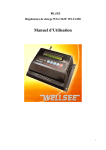
CMP(30A—45A)
Solar Charge Controller
USER’S MANUAL
Please read the manual carefully before you use our products!
Catalogue (Index)
1. Security ………………………………………3
2. Feature ………………………………………4
3. System Connection …………………………5
4. Operation ……………………………………6
5. Fix the Breakdown …………………………8
6. Accessory Installation ………………………9
7. Technical data…………………………………9
2
1.
Security
The factors referring to body and property security have been considered during
designed the products. But incorrect connection will cause to breakdown. For your security,
please do everything according to the following regulation.
·Please contact the local agent before installation, which should be guided by professional
·Prevent any liquid from spattering on controller. Do not clean the controller with wet cloth
·Keep children and incapacity person away from controller
·Keep controller away from electrical heater, warmer and other source of heat; avoid controller
under Sun.
·Please check the rated voltage of solar panel, battery, and loads before connection. Their rated
voltages all should be 12V (or 24V).
·Pay more attention to connect the positive and negative pole among Solar panels, Battery and Loads
correctly..
·The diameter of connecting cable could not be smaller, which should be suited to loads.
·The total rated current of solar panel and loads are kept lower than controller’s rated current.
·Tight and good connection among components.
·Connecting wired battery positive and negative poles directly is prohibited.
3
2.
Feature
CMP (30A-45A) solar charge controller is controlled by CPU, According to the voltage of
battery , controller will adjust the charge current and decide if to supply the loads electricity.
The following is the detailed performance:
·Generally keep the battery on full voltage condition.
·Prevent the battery from over-charging and over-discharging.
·Prevent supplying electricity from the battery to solar panels during nights.
·Reverse Polarity Protection for Battery
·Reverse Polarity Protection for Solar panels
·When the current of load exceeds the rated one of controller, the controller will turn into the
self-protection state and is automatically locked up, the screen shows “Overload”.
·Short Circuit happens; the Controller will turn into the self-protection state and is locked up,
the screen show “Short circuit”.
·Low voltage happens to battery, the controller will automatically separate loads from system.
When the voltage of battery goes up, the loads will automatically restart to work.
·Protection from the lightning strike
·When Controller is normally working, the LCD Screen will show New Charging Current (a
dash“-”before the numeral), Discharging Current and Voltage of battery every 5 seconds.
·Controller is always counting Charging Current Hours and Discharging Current Hours of the
Battery
·When controller start up, according to the voltage level of battery, Controller will self-setup the
Charging-off voltage, the Load-off voltage, the Load-on voltage. These datum is tacitly approved
4
under the standard environment temperature 25℃.
·According to varies system temperature, the controller will automatically compensate the
temperature of the charging voltage.
·Users could setup the Charge-on or off voltage, the load-off voltage, the Load-on voltage, etc,
according to their requirements.
·To prevent battery from over discharging, Controller will automatically control the lowest
Load-off voltage of the load, which is no less than 10V (as per 12V battery) or 20V (as per 24V
battery) or 40V ( as per 48V battery) . If voltage of the battery is less than 10V (or 20V,40V ), the
button “-” will stop working.
·To recover its defaults, please keep pressing down the button “Menu” for over 5 seconds.
5
3.
Connection
As form
·Connect “+” and “-” poles of battery with the correct ports on the controller (the third and
fourth ports from the left).
·Connect “+” and “-”poles of solar panel with the correct ports on the controller (the first and
second ports from the left).
·Connect “+” and “-” poles of load with the correct ports on the controller (the fifth and sixth
ports from the left).
Attention!
·Correctly connect the electrodes of battery ,solar panels, and loads!
·Choose the proper cable according to the current of the loads; the diameter could not be
smaller. The cable 6m ㎡ minimum is suggested!
Sketch of Connection
6
4.
Operation
LCD Screen
Button is down
·Startup
SOLAR REGULATOR
OK
Battery xx.xV
Charge xx.xA
Load xx.xA
·Menu
Battery xx.V
Charge xx.xA
MENU
SOLAR REGULATOR
Load xx.xA
·Check the system temperature
SOLAR REGULATOR
MENU
Temperature xxx℃
OK
·Check the charging current
Temperature xxx℃
MENU
Charge xxxxxxAh
OK
·Check the discharging current
Charge xxxxxx Ah
·Check the battery capacitance
7
MENU
Load xxxxxx Ah
OK
Load xxxxxx Ah
MENU
Battery SOC xxx%
OK
Charge off xx.xV
OK
·Check the charge-off voltage of battery
Battery SOC xxx%
MENU
·Setup the Charge off voltage of battery
Charge off xx.xV
Charge off xx.xV
OK
·Check the load-off voltage of loads
Charge off xx.xV
MENU
Load off xx.xV
OK
·Setup the Load-off Voltage of loads
Load off xx.xV
Load off xx.xV
OK
·Check the load-on voltage of loads
Load off xx.xv
MENU
Load on xx.xv
OK
Load on xx.xV
OK
·Setup the load-on voltage of loads
Load on xx.xV
·Adjust Charge-off voltage of Battery, Load-off Voltage of loads and Load-on Voltage of loads into the
defaults
Press down
MENU
for more than 5 seconds
8
·Startup for over-loads
Reduce quantity of loads
Overload
Reset
SOLAR REGULATOR
OK
·Startup for short circuit
Remove malfunction
Short circuit
Reset
5. Fix
SOLAR REGULATOR
OK
the breakdown
·phenomenon:Green light goes out, the loads stops working, and LCD Screen shows
Battery low
Reason:Low voltage of battery
Solution:Charge up the battery or change the battery
·phenomenon:Green light goes out, the loads stops working, and LCD shows
Over load
Reason:Overload
Solution: Reduce the quantity of loads and then press Button
Reset
·Phenomenon:Green light goes out, the loads stops working, and LCD Screen shows
Reason:Short circuit is happening to loads.
Solution:Disconnecting the malfunction and then press the button
9
Reset
Short circuit
·Phenomenon:Green LED is light
Loads are normally working
·Phenomenon:Red LED is light
Battery is charged up rapidly
·Reason:Red LED is flickering
Battery is in constant voltage (or floating ) charged up
·Phenomenon:Red LED goes out
Reason:Charge-off of battery
Solution:This is the common phenomenon during nights. If it is so during days, please carefully check the
connection among Solar panels, Controller and Battery.
10
6. Accessory
Installation
·Component:near-distance thermoscope
Installation:Plug the thermoscope into the socket (right side) of controller before running of controller, and
then connect batter with the controller. The thermoscope will normally work after one minute.
(According to the fourth Chapter-Operation, the environmental temperature of controller will be
available).
·Component:Long-distance thermoscope
Such thermoscope is suitable to the following condition—the location of battery is far away from
the Controller. (please show us the length of cable between battery and controller for ordering the
proper thermoscope)
Installation:Plug the thermoscope into the socket (right side) of controller before running of controller, and
then connect batter with the controller. The thermoscope will normally work after one minute.
(According to the fourth Chapter-Operation, the environmental temperature of controller will be
available).
7. Technical
Model
Rated Voltage
Loading current Max
CMP45
12V、24VAutomatic distinguish Voltage or 48V
30A——45A
Full charge cut
13.7V/12V;×2/24V;×4/48V Recognize tacitly、rest
Low voltage cut
10.5V/12V;×2/24V;×4/48V Recognize tacitly、rest
Reconnected voltage
Temperature compensation
11
datum
12.6V/12V;×2/24V;×4/48V
-3mv/cell.℃ Recognize tacitly、rest
No load loss
≤45mA
Wire area Min
16mm²
Voltage drop
<270mv
12