1
SOLAR TORRENT
Solar Charge Controller Series
The Solar Charge Controller offers by SolarTorrent.com are for use in solar photovoltaic systems,
which coordinate the working of solar panels, batteries, and loads. It adds protection functions,
so that the entire system can be used safely and efficiently.
WS-C series charge controllers are applicable to all types of photovoltaic panels and various
types of batteries, MCU (Micro-Processing Controller) has PMW (Pulse Modulation
Wide-frequency) 0~100% variable duty cycle process. According to the types and actual
charging situation of the battery, WS-C controller series can provide fast and best charging
voltage and electricity from the PV panel. C30 and C60 series are equipped with advanced
man-machine interactive function, so the user can adjust the charging voltage.
Function:
1.
Overloading protection
2.
Short circuit protection
3.
Conversed discharge protection
4.
Reversed polarity connection protection
5.
Thunder protection
6.
Low voltage protection
7.
Overcharge protection
8.
Batteries stop and charge voltage HVD sets up
9.
Charge and low voltage LCD sets up
10. Display the capability of the battery SOC
11. Loads and comeback setups.
12. Intellectualized temperature compensation
13. Store, calculate, and display the charged AH on the LCD screen.
14. Store, calculate and display the discharged A on the LCD screen.
15. CPU control and LCD-display
16. Working temperature:-25℃-100℃
Model (LCD-display)
Rated Voltage
Max Load current
WS-C2425 /20A
12V/24V
20A
WS-C2425 /25A
Automatic voltage recognition
25A
Input current range
12V~17V/24V~34V
Length≤1m
<0.25V
Charge loop drop
Length≤1m
WS-C2425 /30A
<0.15V
Discharge loop drop
Over voltage protection
17V/34V
Full charge cut
13.7V/27.4V
Low voltage cut
10.5~11V/21V~22V
Temperature compensation
-3mv/℃/cell
No load loss
≤10mA
Min wire area
4mm2
Ambient temperature
-25℃——100℃
30A
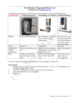
•
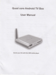
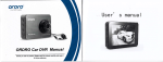
2. FEATURES
Solar Controller
WS-C2425 / WS-C2450
USER'S MANUAL
WS-C24:? 5
WS-C2450
1. SAFETY
Full consideration to the safety of perSllns "nd pruperty
has been gil"_" when llesigning the products, i :"wev,.r the
incorrect COtllh'::L:tion H1JY cause the systC]]l brl"J:\du\\ifl 0f
even safety "ccidem, For your sarety and in'clests, the
fllilowing rule, must be complied during the "per:r: lun,
Installatiul: of this product shall be cal ::d out by
professional suffs,
Prevent any liquid spattered on the contruller. Do not
clean the conti oller with wct cloth.
Keep children and incapacity persons aW,ly horn the
controller.
Keep th,' controller away from dectrical IL:ller. heating
I11<lchini.: and . lthcr high temperature electric;:l ;lppJiallccs:
avoid the controller from direct sunlight.
Please check the rated voltage of solar panel. battery. and
loads before cunnection, Their ['ated volta"cs all ,hlHlld be all
12V (or 24Vj
Make sure allthe positive and negative polc" l'onncetillns
between Solar panels, Battery and Loads are COITeCt.
The dial1l,'tcr of cannel' ling cable must be nnteh with the
requirements ufthe currcnt.
The tOlal rated current of solll!' panel and IUllds must be
smaller than the controller.
Components of sy-,tcm must be correctly l'nd firmly
connected.
Make Sllil' the positive and negative pules ,if the wired
battery art? 11\): ~hort-circuitcd.
WS-C:~4:" and WS-C2450 sll!.:r charge controller arc
controlled by CPU, so they are able t,j control the charge current
and decidc whcther to supply power U the loads according to the
voltage ofbatkrY The product has thc [(;Ilowing features:
Always kC'CjJ the battery on full VO:ll,ge conditilH~.
Prevent the battery thlm over-charging,
Prevent the batlery ti'oil1 over-discbrging,
Prevent thc battery hom reverse charging to solar panels
during nights.
Reverse Plliarity Protection for Balkry
Reverse Pularity Protection for So!:,r panels
When the elllTCIl\ of thc load excleds the rated CUlTcnt of the
controller. thL' Ccll1trolkr will aelivate Illl protcctilln mude and lock
"p. the LCD shuws "Overload"
When thc load short circuited, till' ,'ll!ltroller wili activ:,tc \i:c
protectiuli I:;:,,', :liid !l!_'k up. the LCD.buw "Short circuit"
When lil,' b~ttery voltage is low. the controller will
automatically Cllt off the load from tht' system and the LCD shows
"Battery low" , If the voltage ofbatlery is back to normal and the
load will rest:lrl working,
Thunder l"'otection
Whell the cUl1troller is normally \\orking. the LCD will show
the voltage 01 battery, charging eurrelI and current of loads in turn
of c\'~ry 5 SCl'lil\(jS.
The eUlltruller can remember tk charging current data and
discharging eUllent data of the baltcry'
When suns up, the controller 11':11 sdf~setup the charging-orr
voltage, the I"ad-off voltage and the [,'ad-on voltage according to
the voltage of [Jattery. These default par:'mcters bring into clTeet in
the standard environment temperature ( 25',().
Accordin," to varies system tcl1'l'crature, the controller will
[lutonutically cDmpcnsate the temperClture of the charging voltage.
Users could setup the charge-on ,'r ofr voltage, the load-otT
voltage, the 11l,:ld-on volwge, etc, accOl~:,:ng to users" requirCl11cnts.
1'0 prevcnt battery from over di',:harging. the controller ;\'ill
automatically control the lowest 10ad-ulT vollage of tbe load, which
is no less than IOV (as per 12V batter\) or 20V (as per 24V battery),
If voltage or tlJe ballery is less than I ',I\' (or 20V), the button "-"
will stop working.
To reco\er thc default parameters, please keep preSSing the
bullon ",",1c'nu" for more than 5 sec'l:nds.
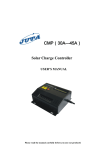
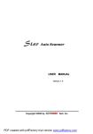
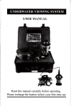
3. CONNECTION
As indicated in diagram: Connect "+" and "-" poles of
solar panel with the correct terminals l>I' the controller (the first and
second termil,ah from the left).
Connect ., +" and "-" po':, of battery with the correct
terminals on the cOlltroller (the third and fourth terminals Ii'om the
left ),
and
p.;!cs of load with the correct
Connect
terminah un the cuntroller (the frlil, :lnd sixth terminals from the
left).
Attention'
First eOll'leet the solar controller v\ ith the battery,
Correctly connect the electrode; of solar panels. battery and
loads.
Chuuse the proper wire according to the current of the loads; it
is suggested lhat the diameter of \'/S-C2425 lllust bigger than 4
1Il1l1' and \\,')·C2..50 lllust bigger th,,:, 6 mm'.
2
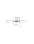
Check the battery capacitance
~B-at-te-'r-y-~-O
Solor controller'
0
I SOCxxx%
Check the charge-off voltage of battery
g
_>,
Charge off
~ \ xx.xV
pQnels
%ttet'J'
Setup the Charge off voltage of battery
Diagram of Connection
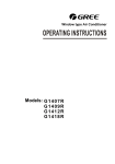
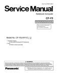
4. OPERAnON
Charge
olTxx.xV
[fnot reset, the controller will use the default paLlllleters.
(~
) - - - - LCD Screen
c=Jf.------ B litton is pressed
Check the load-off voltage of loads
~MENUf---~
I
\
Load off
xx.xV
Startup
( Wellsec
SOLAR
Setup the Load-off Voltage of loads
{I]-i
Menu
\
I_{
Load off
xX.xV
.
I
@-i
~
f--I--> MENU 1 - - - - »[
,--,-"",,-cc:..::~
y.,'cllsce
SOLAR
\
Load off
xx.xV
~EJK
/
Check the load-on voltage of loads
(.
Load on
xX.xv
LQ-__.
Load on
xX.xv
~
Setup the load-on volta-::Je of loads
Check the system temperature
Well sec\
SOLAR
,,_T_Cn_l_p_er_a_tl_lr_C
_xxx'C
Q
L.:J
:----.
J
rill-I
G
.
Load on
. xx.xV
1
LQ
rD
~-
k .
Check the charging current
~---
MENU _~ Charge
\ xxxxxxAh
~Q
/ L.:J
Startup for over-loads
SOLAR
Check the discharging current
,------.,
Charge
xxxxxxAh
Startup for short circuit
3
HI
OK
Technical Index:
5. TROUBLE SHOOTING
Trouble: Green light goes out, the loads stops working,
and LCD show,
Reason: l_ow voltage of battery
UJ-:;~t~
~~
Model
---
WS-C2425 20A
WS-C242525A
Solution: Charge the battery or change the hattery
Rated Voltage
12V/24V AutOmatic distinguish voltage
Trouble: Green light goes out, the loads stops working,
r~'er IO:icl )
and LCD shows
Reason: Overhad
Solution:
'----
Reduce the quantity of loads and then press
C_ RescQ
Button
Trouble: Green light goes out, the loaels stops working,
and LCD shows
G~~~~lr?llt)
Reason: The loads Short circuited
Solution: Eliminating the malfunction and tben press
C~~ Res~
the button
Phenomenon: Green LED is on
Loads are normally working
Phenomenon: Red LED is on
Battery is charged up strongly
Phenomenon: Red LED is flickering
Battery is charged up in cunst:)Jlt voltage (or
110ating)
Trouble: Red LED goes out
Reason: (Jut of power
Solution: This is the common phenomcnon during
nights. If it is not charging for a long time, plca.c carefully
check the connection among solar pancls, controllcr and
battery,
i
Loading
current Max
20A
25A
Full charge cut
13.7V/27.4V
Low voltage cut
IO.5-IIV/21V-22V
Temperature
compensation
-3mvrC/cell
No load loss
~30mA
Wire areil Min
The max Wire
Diameter specification: 1m
Voltage drop
4mm
<240m v
Working
Temperature
Model
2
<270mv
~25"C-lOO"C
WS-C2450 40A
WS-C2450 50A
~
6. ACCESSORY INSTALLATION
Standard Accessory: Near-distance thern1<'scope
Installation: Plug the thermoscope into the "'Jeket (top)
of controller before running of controller, and th,:n connect
battery with the controller. The thermoseopc will normally
work aftcr one minute. (Operatc as indicated in the Fourth
Chapter; the environmental temperature of controller will be
showed on LCD).
Optional Accessory: Long-distancc thcrmoscopc
Such thermoscope is suitable to thc following
condition- the location of battery is far aW:lY from the
controller.
Installation: Plug the thermoscope into the socket (top)
of controller before running of controller, and lhen connect
battery with the controller. The thermoscopc \\ ill normally
work aftcr one minute. (Operate as indicated in the fourth
Chapter; thc environmental temperature of contruller will be
showed on I.e Il).
Rated Voltage
Loading
current Max
l2V/24V Automatic distinguish voltage
Full charge cut
Low voltage cut
50A
40A
13.7V/27.4V
IO.5V-ll V/2l V-22V
Temperature
compensiltion
-3mvrC/cell
No load loss
~45mA
Wire area Min
6mm'
The max Wire
Diameter specifi
cation: 1mVolto ge drop
<240mv
Working
Temperature
<270mv
-25"C-IOO"C
Notice: WS-C4S60 (48V45A, 48V6i'A) solar controller&
WE LLS EE II OA solar cantrall: r are coming soon!
5
6