1
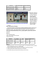
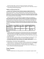
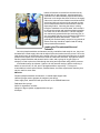
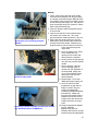
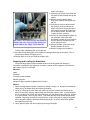
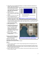
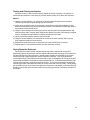
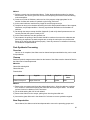
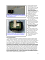
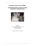
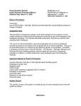
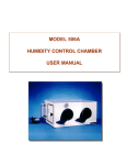
Table of Contents
User manual part II: running the POSaM Platform.........................................................................................3
Overview.....................................................................................................................................................3
Slide Surface Preparation.................................................................................................................................3
In-House Epoxysilane Slide Preparation....................................................................................................3
Materials:...................................................................................................................................4
Methods:....................................................................................................................................5
Commercial Slide Alternatives...................................................................................................................7
Reagent Preparation..........................................................................................................................................7
Overview:....................................................................................................................................................7
Solvent Preparation.....................................................................................................................................7
Materials:...................................................................................................................................7
Methods:....................................................................................................................................8
Phosphoramidites and Tetrazole.................................................................................................................9
Materials:.................................................................................................................................10
Methods:..................................................................................................................................10
Base Deprotection Solution......................................................................................................................11
Materials:.................................................................................................................................11
Methods:..................................................................................................................................11
Acetonitrile Wash Solvent........................................................................................................................12
Materials:.................................................................................................................................12
Methods:..................................................................................................................................12
Oxidizer and Deprotection Acid...............................................................................................................13
Materials:.................................................................................................................................13
Methods:..................................................................................................................................13
Arrayer Operation...........................................................................................................................................13
Overview...................................................................................................................................................13
Loading the Phosphoramidites and Tetrazole..........................................................................................14
Materials:.................................................................................................................................14
Method:....................................................................................................................................15
Preparing and Loading the Substrates......................................................................................................16
Materials:.................................................................................................................................16
Method:....................................................................................................................................16
Priming the Bulk Reagents.......................................................................................................................17
Method:....................................................................................................................................17
Testing and Clearing the Nozzles.............................................................................................................18
Method:....................................................................................................................................18
Drying Down the Enclosure.....................................................................................................................18
Materials:.................................................................................................................................19
Method:....................................................................................................................................19
Pre-Washing the Slides.............................................................................................................................19
Method:....................................................................................................................................19
Initiating Synthesis...................................................................................................................................19
1
Method:....................................................................................................................................20
Post-Synthesis Processing..............................................................................................................................20
Overview...................................................................................................................................................20
Cleanup.....................................................................................................................................................20
Materials:.................................................................................................................................20
Method:....................................................................................................................................20
Base Deprotection.....................................................................................................................................20
Materials:.................................................................................................................................21
Method:....................................................................................................................................21
Shutting Down the Arrayer.......................................................................................................................21
Control Hybridization for Quality Control....................................................................................................21
Overview...................................................................................................................................................21
Hybridization............................................................................................................................................21
Materials:.................................................................................................................................21
Post-Hybridization Washes......................................................................................................................23
Materials:.................................................................................................................................23
Scanning....................................................................................................................................................24
Materials:.................................................................................................................................25
Method:....................................................................................................................................25
Interpretation.............................................................................................................................................25
Maintenance and Troubleshooting.................................................................................................................26
Clearing Clogged Inkjet Pumps................................................................................................................26
Cleaning the Phosphoramidite and Tetrazole Supply Vials.....................................................................26
Materials:.................................................................................................................................26
Method:....................................................................................................................................26
Changing the Inkjet Head.........................................................................................................................27
Materials:.................................................................................................................................27
Method:....................................................................................................................................27
System Properties...........................................................................................................................................28
System Performance.................................................................................................................................28
Speed and Failure Rate............................................................................................................28
Spot Diameter..........................................................................................................................29
Hybridization Specificity.........................................................................................................29
Two-color Hybridization.........................................................................................................29
Cost of Operation....................................................................................................................30
Future Improvements................................................................................................................................30
Appendix A: INKJET ARRAYER STARTUP PROCEDURE CHECKLIST.............................................31
2
User manual part II: running the POSaM Platform
Overview
Oligonucleotide synthesis has been an efficient processes since Itakura described the
phosphotriester method of oligonucleotide synthesis in the mid 1970s. Reactivity, speed,
coupling efficiencies, and recoveries have continued to improve, especially since the advent of
automated oligonucleotide synthesizer, and much of the groundwork necessary for inkjet
oligoarray synthesis had already been layed by these early investigations.
One problem, however, is that the preferred solvent for oligonucleotide synthesis, acetonitrile,
is too volatile to work well during inkjet synthesis. Since the picoliter-size droplets are flying
through the air at the speed of a flying bullet, the acetonitrile tends to evaporate so rapidly that
sometimes it is gone even before it hits the slide surface. This high volatility results in frequent
misplaced droplets, crystals of reagent sitting dry on the slide, and a very high rate of clogging
the piezoelectric nozzles.
Blanchard and Hood suggested that the ideal inkjet solvent should have low volatility, a
higher boiling point than acetonitrile, higher vapor pressure, be compatible with phosphoramidite
synthesis, and not harm the inkjet array head. They eventually showed that propylene carbonate
(PC) met these requirements and had a coupling efficiency close to that seen with acetonitrile.
The University of Washington patented propylene carbonate as a solvent for inkjet
oligonucleotide synthesis, and granted Rosetta Inpharmatics (and then Agilent), exclusive rights
to use propylene carbonate for oligoarray synthesis. To remain clear of patent infringements, we
are have continued the search for the best solvent to use for inkjet oligoarray synthesis. We
have found that a 1:1 mixture of 2-methyl glutaronitrile (MGN) and 3-methoxypropionitrile (3MP)
works as well as PC, and appears to cause less nozzle clogging (unpublished observation).
If care is taken to follow the instructions outlined herein, and to maintain a scrupulously water
free environment, labs building the POSaM platform should have little trouble constructing
arrays. Selecting and printing the oligonucleotides best suited for the quantification of unique
mynas, genes, or splicing sites is a different case, however, and will still require empirically
testing different sequences to find those that discriminate best. As more people use the
POSaM platform we will be able to build an annotated library of reporters known to identify
specific mRNAs. Use of the POSaM platform for developing and testing novel array designs,
developing empirical data on probe performance, and experimenting with new applications for
microchip technologies should provide a stable, accessible, inexpensive tool for basic research
laboratories
Another critical factor is the surface chemistry of the solid substrate. We have tested a wide
range of commercial substrates, and found that none of them can consistently deliver the
balance of reactivity and hydrophobicity necessary to produce discrete, round, evenly-spaced
features with an acceptable coupling efficiency to the slide surface. Although some commercial
slides work reasonably well, in our hands the lot-to-lot, and even intra-lot, variations result in a
very high failure rate (>50%).
We developed a simple and effective method for surface-modifying our own slides, and have
found this to be a much more stable and reliable approach. Protocols are presented in this
manual for both the custom modification process and the use of commercial substrates, so that
the end user may determine what is preferable in their situation.
Slide Surface Preparation
In-House Epoxysilane Slide Preparation
The critical balance of hydrophobicity and reactivity necessary for successful inkjet array
synthesis is achieved by using a reactive epoxysilane capable of covalent attachment to the
silanol groups on the glass surface in a background of longer-chain silanes which also attach to
3
the glass but provide the hydrophobic properties and do not participate in base attachment
during synthesis. These hydrophobic silanes are obtained by using RainX. Yes, RainX (the
commercial treatment you use on your windshields to make rain bead up). We are currently in
the process of testing the individual components to obtain the minimum necessary formulation
and concentrations of silanes, so we are not tied to a specific commercial product with unknown
purity and quality control. However, RainX is extremely cheap and has been incredibly effective
in obtaining the correct surface properties.
Materials:
FisherFinest microscope slides
Chemical fume hood
6-8 Glass slide staining dishes
4-6 glass slide staining racks
Wire handle for staining racks, dedicated for nanostrip
Wire handle for staining racks, dedicated for silanizing
Nitrogen or Argon cylinder equipped with a blow gun
P-1000 pipettor
P-1000 compatible pipette tips
100ml pyrex graduated cylinder
250ml amber glass bottle
Cap for 250ml bottle with either Teflon liner or Teflon-lined septa
Medium-size sonicating water bath (> 4.5in x 6in x 4 in bath)
Blotter material cut to fit into the base of a slide staining rack
Clean plastic slide storage boxes sufficient for the number of slides.
Chemical
3-(glycidoxypropyl)
Supplier
Sigma-Aldrich
Cat #
Supplied
44016-7
100g bottle
Abbreviations
3-GPTMS
trimethoxysilane
RainX
Pennzoil Quaker-State RX11212
207ml bottle RainX
Sodium Hydroxide
Acros Organics
Hydrochloric Acid,
Concentrated (12M)
Fisher Scientific
A144-212
Nanostrip
Cyantek
NC9096760 1 gallon
Nano
Ethanol, 200 proof
Aaper Chemical
n/a
1 gallon
EtOH
Acetone, HPLC-grade Fisher Scientific
A949-4
4L bottle
Acetone
Methanol, HPLCgrade
Fisher Scientific
A452-4
4L bottle
MeOH
18M-ohm Milli-Q water
n/a
n/a
n/a
18MΩ H2O
206060010 1kg bottle
2.5L bottle
NaOH
HCl
4
Stock Solution: 10% Sodium Hydroxide, 1L
Chemical
Sodium Hydroxide
Amount
100g
Initial Conc,
n/a
Deionized Water
800ml
n/a
Q.S. to 1000ml with deionized water.
Final Conc,
10% w/v
n/a
Stock Solution: 1% Hydrochloric Acid, 1L
Chemical
Conc,. HCl
Amount
27ml
Initial Conc,
37.5%
Deionized Water
800ml
n/a
Q.S. to 1000ml with deionized water.
Final Conc,
1%
n/a
Stock Solution: 2.5% 3-GPTMS in RainX, 250ml
Chemical
Amount
Initial Conc,
Final Conc,
3-GPTMS
6.25ml
97.0%
2.5%
RainX
243.75ml
n/a
97.5%
Methods:
1) Fill several glass racks (usually 4-6) with 19 slides per rack, loaded in a zig-zag pattern with
every other slide racked diagonally.
2) Fill 2 glass staining dishes 2/3 full with nanostrip. CAUTION: nanostrip is a concentrated acid
mixture containing hydrogen peroxide. It is extremely aggressive against organic material,
and should be considered very hazardous. It reacts exothermically with water, oxidizing
agents, and organic solvents. It should be used only neat, never diluted or mixed with other
chemicals. During storage, peroxides in nanostrip and waste materials can decompose, so it
must always be stored in a vented bottle to prevent over pressurization and explosion.
Materials in contact with nanostrip must be clearly marked, and thoroughly rinsed with
deionized water immediately after use. Any spills must be cleaned up immediately.
Nanostrip should only be used in a chemical fume hood, with appropriate protection against
splashes, spills, and other exposure. Wearing nitrile gloves, goggles, and a laboratory coat
should be considered the minimum protection; elbow-length rubber gloves, sleeve protectors,
a face shield, and a chemical apron offer a higher degree of protection.
3) Using the wire handle, gently lower the glass racks into the nanostrip and agitate up and
down 2-3 times to dislodge bubbles and ensure full contact on the slide surface. Remove
wire handle immediately.
4) Incubate at RT for 1 hour.
5) Carefully remove each rack from the staining dishes and rinse thoroughly under running
deionized water. Immerse each rack in a staining dish filled with deionized water and
incubate for 20 minutes at RT.
6) Repeat step 5 for 2 additional cycles.
7) Fill each staining dish 2/3 full with 10% (w/v) NaOH solution and place the slide racks into the
dishes. Incubate at RT for 1 hour.
8) Carefully remove each rack from the staining dishes and rinse thoroughly under running
deionized water. Immerse each rack in a staining dish filled with deionized water and
5
incubate for 20 minutes at RT.
9) Repeat step 8 for 2 additional cycles.
10)Fill each staining dish 2/3 full with 1% HCl solution and place the slide racks into the dishes.
Incubate at RT for 1minute.
11)Carefully remove each rack from the staining dishes and rinse thoroughly under running
deionized water. Immerse each rack in a staining dish filled with deionized water and
incubate for 20 minutes at RT.
12)Repeat step 11.
13)In a chemical fume hood, fill each staining dish 2/3 full with methanol and gently lower the
glass racks into the solvent, agitating up and down several times. Incubate at RT for 5
minutes.
14)Remove slide racks from the methanol and crudely blow excess methanol clear while holding
the slides down in the rack with one hand.
15)Allow slides to air dry in the hood for 1 hour. Racks with slides can be wrapped in aluminum
foil and stored in a desiccant cabinet for up to several weeks before surface modification.
16)Use the waste nanostrip used to clean the slides to clean an empty glass slide rack, an empty
glass staining dish, a 100ml graduated cylinder, and a 250ml amber glass bottle. Only
interior surfaces need to be cleaned. Pour nanostrip carefully into each vessel, incubate at
RT for 30 minutes, then rinse thoroughly with deionized water and air dry.
17)Using a P-1000 pipettor for the 3-GPTMS, and the cleaned graduated cylinder from step 16,
prepare the 2.5% epoxy silane solution according to the above table. Cap tightly and shake
vigorously for 1 minute. Allow to stand at RT for 30 minutes for use.
18)With nanostrip-cleaned slides, place 10 slides into a nanostrip-cleaned glass slide rack.
19)Place the cleaned glass staining dish from step 16 into the sonicating water bath. Best
results have been obtained when the staining dish is suspended in the sonicator, preventing
dampening of the sonic effects by contact between the dish and the bath walls.
20)Fill the bath with water and pre-run the sonicator for 5-10 minutes to degas the bath water.
21)While degassing, fill one staining dish 2/3 full with ethanol, one with Milli-Q water, and one
with acetone.
22)Place the filled slide rack into the cleaned staining dish from step 16, and carefully pour the
silane solution prepared in step 17 into the dish, completely covering the slides.
23)Allow to sonicate for 2 minutes.
24)Remove rack from dish with dedicated wire handle, and hold suspended above the staining
dish for 30 seconds.
25)Immerse slide rack in a staining dish filled with ethanol and agitate up and down several
times. Incubate at RT for 5 minutes.
26)Transfer slide rack to staining dish containing water, and agitate up and down several times.
Incubate at RT for 5 minutes.
27)Transfer rack to staining dish containing acetone, and agitate up and down several times.
Incubate at RT for 5 minutes.
28)Remove rack from acetone and place on top of blotter material in a chemical fume hood,
ensuring contact between the blotter and the slide edges. The blotter prevents silane
accumulation along the slide edge during drying. Allow to drip dry in the hood for approx 1
hour.
29)Carefully transfer the slides to a plastic storage box and label it with the date, identity, and
batch tracking information.
30)Store slides in a desiccating cabinet at RT until use.
6
Commercial Slide Alternatives
We have found commercially-available slides to be problematic for many reasons. Since they
are primarily intended for pin-spotting applications, they are frequently insufficiently hydrophobic
for use with an inkjet. Those that do demonstrate suitable droplet morphology are prone to
extreme variations in their quality as substrates with the POSaM system. Despite concerted
efforts, we have been unable to recommend the use of a particular slide or slide type.
That said, we have had partial success using epoxysilane slides supplied by Bioslide (Walnut,
CA) and Xenopore (Hawethorne, NJ). For users wishing to experiment with these or other
commercial slide types, we recommend storage in sealed vapor-barrier bags (the anti-static type
used to ship electronics components work very well) containing desiccant packs with indicator.
Slides should be stored in a cool, dry location. Since epoxy is reactive to primary amines,
epoxysilane slides should not be stored in the same Desiccator as amino-modified slides.
Generally, commercial slides should be pre-treated and handled according to the guidelines
used for the in-house slides.
Reagent Preparation
Overview:
The most important factor regarding the reagents for oligonucleotide synthesis is to keep
them dry. Most regents/solvents can be purchased in anhydrous form, and thus only need to be
handled and stored in such a way as to avoid contamination by moisture. Be afraid! Most
synthesis failures are due to contaminating water. Extra precautions are taken with the solvent
mixture (1:1 MGN:3MP), as these reagents are used in every cycle of DNA synthesis.
Fortunately, controlling moisture is a relatively simple process with the POSaM system, and
close attention to detail is all that is required to avoid unexpected problems. However, if you
have a run of failures and are sure you are doing nothing wrong, its probably due to wet
reagents. The easiest thing is to throw them all out and start over again using freshly prepared
reagents.
Solvent Preparation
Generally, 2-4 bottles of the 1:1 MGN:3MP solvent solutions are prepared at once, depending
on the throughput needs of the laboratory. Preparation of solvent well in advance is necessary
due to the need to allow molecular sieve beads to adsorb any residual moisture from the solvent
before use. A typical time between beginning preparation and use is 2-3 days. If prepared and
stored properly, unused bottle of solvent should be good for several months. Typically, solvent is
discarded after a maximum lifetime of 2 months from the date of preparation..
Materials:
100ml Amber Bottles with Septum Cap (Fisher #05-719-182)
PFTE-lined Silicone Septum (Fisher #03-340-4H)
50ml Graduated Cylinder
Parafilm M Lab Sealing Film
Shallow Pyrex dish able to hold 4 bottles
Aluminum Foil
Vacuum Desiccator
Clean Convection Oven capable of 300C
Nitrogen or Argon cylinder equipped with a blow gun
House Vacuum source
5ml polypropylene syringe
26G 0.5in hypodermic needle
7
Orbital Shaker
Ring stand and 3-finger Clamps
Chemical
Supplier
Cat #
Supplied
Abbreviations
3-methoxypropionitrile
Sigma-Aldrich
65290 1L bottle
3MP
2-methyl glutaronitrile
Sigma-Aldrich
67020 1L bottle
MGN, GLUT
Molecular Sieves, Type 3A
Fisher Scientific
M564-500
500g bottle
MolSieve
Acetone, HPLC-grade
Fisher Scientific
A949-4
4L bottle
Acetone
Citranox Lab Detergent
Fisher Scientific
0432212A
1 gallon
Citranox
Methods:
1) Wash graduated cylinder, bottles, caps, and septa with 1% Citranox in warm water, rinsing
thoroughly with deionized water. Rinse with acetone and allow to fully dry inverted.
2) Place bottles and graduated cylinder in convection oven at 250C for 30 minutes.
3) Remove from oven and allow to cool sufficiently for safe handling. Cap graduated cylinder
with aluminum foil and set aside. Add approximately 25g of molecular sieves to each amber
bottle. Cap immediately.
4) Set oven to 300C. Wrap pyrex dish in aluminum foil. Remove caps, place bottles
containing molecular sieves in the pyrex dish, and bake in oven for 16-24 hours (overnight).
5) Remove bottles from oven carefully (300C is very hot, use appropriate thermal gloves and
caution when handling hot materials) and immediately flush each bottle with dry gas.
6) Place pyrex dish with bottles in Desiccator. Pull maximum vacuum to evacuate air from the
Desiccator. Directing a stream of dry gas into the valve as vacuum is released, flood the
Desiccator with dry gas.
7) Repeat the vacuum/dry gas flush 4 times. Leave bottles under vacuum for 1 hour to cool.
8
8) Using graduated cylinder prepared
above, add 50ml of 3MP and MGN
to each bottle. This should almost
completely fill the bottles (almost
no head space).
bottles immediately with septa
Septa-Lid Seal Ok 9) Cap
caps. Carefully seal the cap to the
bottle with parafilm, being careful to
cover the entire septa, and the joint
Septa-Bottle Seal
between the cap and the neck of
not so good
the bottle. See cross-sectional
illustration below.
Sealed, Protective
Airspace Barrier
10) Fill 5ml syringe with dry gas and
inject gas into bottle through
septum. This provides positive
pressure in the bottle and prevents
Parafilm
the entry of atmospheric moisture
Lid-Bottle Seal
during storage.
11) Label bottle with the contents,
Parafilm:
date, and owner name.
Gives Extra Barrier to Septa-Bottle
12)
Shake bottle vigorously for 30
Seal by making closed airspace
seconds,
place on orbital shaker
through Lid-Bottle Seal.
overnight.
13) Store bottles inverted clamped on
a ring stand (see picture below).
Allow bottles to sit undisturbed for 2-3 days, so fines and particulates can settle. Solvent
solution should be very clear after settling. Cloudy solvent is an indication of moisture and
should be discarded.
Cross Section of Open-Top
Lid/Septa/Neck on Bottle Used
For Dry Storage of PC.
Phosphoramidites and
Tetrazole
Storage of solvent in inverted, parafilm-sealed bottles.
The phosphoramidite monomers
and the tetrazole catalyst are the
basic building blocks for nucleic
acid synthesis. As oligonucleotide
synthesis has become such a
common and widespread
technique, a variety of synthesis
reagents have become widely
available in appropriate packaging
sizes such that the costs of
qualifying, aliquoting, and handling
these materials can be greatly
reduced.
Because the POSaM platform
uses so little material, the vast
majority of the monomers and
catalyst are “wasted” for bank loading, priming, and nozzle testing. These materials are not
terribly stable once in solution, again primarily because of their tendency to react unfavorably
with trace amounts of moisture. For this reason, they are generally purchased in the smallest
packaging available, dissolved and used for a relatively short time (generally 3 days), and then
discarded.
9
Materials:
6x 26G 0.5in hypodermic needles
2x 5ml polypropylene syringe
4x 1ml polypropylene syringe
Nitrogen or Argon cylinder equipped with a blow gun
Rotary mixer
Chemical
Supplier
Cat #
Supplied
100ml
Abbreviation
Solvent, prepared previously (2-3 days)
n/a
n/a
Solvent, Nitrile
Solvent
dA-CE Phosphoramidite
Glen Research
10-1000-02 250mg vial A
Ac-dC-CE Phosphoramidite
Glen Research
10-1015-02 250mg vial C
dG-CE Phosphoramidite
Glen Research
10-1020-02 250mg vial G
dT-CE Phosphoramidite
Glen Research
10-1030-02 250mg vial T
5-ethylthio-1H-tetrazole
Glen Research
30-3040-10 1g vial
TET
Methods:
1) Phosphoramidite monomer vials are stored at RT sealed in ziplock bags in a vacuum
Desiccator at partial vacuum under argon. Tetrazole is stored sealed in ziplock bags
refrigerated at 4C. These reagents are supplied lyophilized in septa-capped vials.
2) Remove 1 vial of each phosphoramidite from the Desiccator, draw a partial vacuum on the
Desiccator, flood the Desiccator with dry gas, and draw a partial vacuum again. Remove 1
vial of tetrazole from the fridge.
3) Bend the pull tabs back to expose the septum sampling holes on the vial caps, but do not
break or remove the sealing ring.
4) Label 2 5ml syringes with 26G needles as “TET” and “GAS”. With the “TET” syringe, slowly
withdraw the appropriate volume of solvent (from the table below) for the tetrazole, taking
care not to introduce bubbles of atmosphere, and inject it through the septum into the vial.
With the “GAS” syringe, inject a slightly greater volume of dry inert gas (drawn from the
blowgun on the gas cylinder) back into the solvent bottle to maintain positive pressure. Set
syringes aside for loading.
5) Label 4 1ml syringes with 26G needles as “A”, “C”, “G”, or “T”. Using the appropriate
syringes, withdraw the appropriate volumes of solvent (from the table below) for the
phosphoramidites and inject it through the septum into the various vials. With the “GAS”
syringe, inject 5mls of dry inert gas back into the solvent bottle to maintain positive pressure.
Set syringes aside for loading.
Chemical
dA-CE Phosphoramidite
Final Concentration
Volume of Solvent
0.25M
1.16ml
Ac-dC-CE Phosphoramidite 0.25M
1.3ml
10
Chemical
Final Concentration
Volume of Solvent
dG-CE Phosphoramidite
0.25M
1.2ml
dT-CE Phosphoramidite
0.25M
1.34ml
5-ethylthio-1H-tetrazole
0.625M
12.4ml
Prepared phosphoramidites and Tetrazole on the rotary mixer.
6) Secure the 5 vials to a
rotary mixer, and allow
to slowly rotate at RT
for >1 hour. After 30
minutes, rotate the
vials 90 degrees to
ensure full coverage of
the internal surfaces by
the solvent. 1 hour is
the minimum amount of
mixing to completely
dissolve the reagents.
Allow to continue
mixing until ready to
load the POSaM
instrument.
Base Deprotection Solution
Once an array has been synthesized, the cyanoethyl phosphate protecting groups must be
removed from the bases to allow the hydrogen bonding between base pairs to occur in the
hybridization process. This is performed by a strong base, in the form of ammonia in a
methylamine solution (abbreviated as “AMA”). To ensure stability of the ammonia, both the
stock ammonia and the AMA solution are stored tightly capped in a plastic bottle at 4C in a
refrigerator.
Materials:
100ml Graduated cylinder
Plastic 100ml Nalgene screw cap bottle
Chemical fume hood
Chemical
Supplier
Cat #
Supplied
Strong Ammonia, 26%
in aqueous solution
Fisher Scientific A617-212
2.5L bottle
n/a
Methylamine, 40% in
aqueous solution
Sigma Aldrich
1L bottle
n/a
426466-1L
Abbreviation
Methods:
1. Wearing nitrile gloves, a lab coat, and safety goggles, use the graduated cylinder to transfer
50ml of methylamine solution to the plastic bottle.
2. Add 50ml ammonia solution, being sure to immediately recap the stock solution.
3. Cap the plastic bottle and shake vigorously for 30 seconds.
4. Store AMA solution (and ammonia stock solution) at 4C until use.
11
Acetonitrile Wash Solvent
Acetonitrile is used to wash particulates, unreacted phosphoramidite, and the bulk oxidizer
and acid solutions off of the slides before and after each round of synthesis. As with the majority
of the reagents used, moisture content is critical. Thus, standard electronics and HPLC grades
of acetonitrile are undesirable. Anhydrous (>99.9% purity) grade acetonitrile is preferred, also
described as “synthesis grade”.
Because acetonitrile is used in quantity, purchase of this solvent in 1L bottles eventually
becomes impractical as POSaM throughput increases (handling time, inventory, transport,
bottle disposal, etc.). On instruments running almost continuously, we have found it more
practical (and about 50% cheaper) to purchase in bulk packaging in approximately 20L or 50L
vessels. These are located under the instrument chassis, slightly pressurized, and plumbed
directly to the dispensing valve.
2L low volume vessel and plumbing (left), and 50L high volume schematic (right).
Because regulatory and facilities requirements will vary, we will concentrate on the smallervolume approach as this is what users starting out will likely choose to use.
Materials:
Chemical
Supplier
Cat #
Acetonitrile, Anhydrous Fisher Scientific 61022-0010
Supplied
1L bottle
Abbreviation
ACN, AcN
Methods:
1) Handling of acetonitrile should be done while wearing gloves, safety goggles, and a
laboratory coat. Carefully loosen the locking ring on the supply bottle, and partially withdraw
the bottle cap (Teflon plug cap and locking ring) and attached tubing. Bottle is under approx
3 psi of pressure.
2) Remove the cap from a 1L bottle of ACN, and carefully pour the entire bottle into the 2L pyrex
supply bottle, taking care to minimize splashing and agitation.
3) Re-attach plug cap and locking ring, taking care not to tangle or otherwise foul the pressure
12
and solvent supply tubing. Allow a few minutes for the bottle to fully pressurize.
4) Rinse empty solvent bottle with acetone, followed by 2 water rinses. Allow bottle to air dry in
a chemical hood and discard appropriately.
Oxidizer and Deprotection Acid
The other 2 bulk reagents used in the synthesis process are an iodine oxidizer and a
deprotection acid. The oxidizer is used to convert the phosphate linkage formed from the
previous synthesized base, monomer phosphoramidite, and tetrazole catalyst into a stable
phosphotriester bond. Once this reaction has taken place, the dimethoxytrityl (DMT) protecting
group on the 5' terminus must be removed to expose a free 5'-OH group to serve as the coupling
site for the next successive round of synthesis. The protic acid used to accomplish this reaction
is 2.5% dichloroacetic acid in dichloromethane.
While these reagents may be assembled from individual components, the popularity of
nucleic acid synthesis has made these reagents available in a convenient premixed and qualitycontrolled form from several vendors. There are numerous advantages to purchasing these
premixed chemicals, and we have found this to be very cost-effective when analyzing the labor
and qualification costs of making these reagents ourselves. Users desiring to mix their own
chemicals should keep in mind the need to carefully transfer the materials to avoid introduction
of moisture, and that stability of both the main stocks and working reagents must be considered.
Materials:
Chemical
0.02M Iodine in
THF/Pyridine/Water
Supplier
Cat #
Supplied
Abbreviation
Glen Research
40-4330-57
450ml
Oxidizer
2.5% Dichloroacetic
Glen Research
acid in dichloromethane
40-4042-57
450ml
DCA/DCM,
Depro Acid
Methods:
1) Handling of the oxidizer and deprotection acid reagents should be done while wearing nitrile
gloves, a laboratory coat, and goggles. Carefully loosen the locking ring on the appropriate
supply bottle (bottle is under approx 3 psi of pressure), double-checking that it is correct for
the reagent being loaded. Partially withdraw the bottle cap (Teflon plug cap and locking ring)
and attached tubing.
2) Remove the cap from a bottle of oxidizer or acid, and carefully pour the entire bottle into the
500ml amber pyrex supply bottle, taking care to minimize splashing and agitation.
3) Re-attach plug cap and locking ring, taking care not to tangle or otherwise foul the pressure
and reagent supply tubing. Allow a few minutes for the bottle to fully pressurize.
5) Repeat steps 1-3 for the other reagent, as appropriate.
6) If supply bottles are not empty, it is acceptable to top them off and reseal the chemical source
bottles for future use. We generally store open bottles of deprotection acid in the POSaM
7) instrument enclosure, and open bottles of the iodine oxidizer in a 4C refrigerator.
8) Rinse empty chemical bottles with acetone, followed by 2 water rinses. Allow bottles to air
dry in a chemical hood and discard appropriately.
Arrayer Operation
Overview
When the POSaM instrument is being prepared for use, the appropriate reagents must be
13
loaded, all moisture removed from the enclosure by
flooding with dry gas (nitrogen), nozzles tested and
cleared for use, and substrates prepared and loaded.
When not in use longer than about 24 hours, the supply
vials on the instrument are flushed out and stored filled
and primed with pure solvent to help maintain a clean
and uncontaminated chemical environment inside the
dispensing fluidics. Assuming the arrayer is being
brought to readiness from an idle state, the first step is
to remove this solvent and load the synthesis reagents
into small vials on the instrument. The bulk reagents
are continuously pressurized at 3psi under dry gas, so
are more stable and less prone to absorb moisture than
the phosphoramidites and tetrazole. These are
generally left filled and ready, except for long periods of
disuse when they should be replaced and the tubing
lines primed with acetonitrile.
Loading the Phosphoramidites and
Tetrazole
Once the phosphoramidites and tetrazole are fully resolublized and ready for use, they must
be loaded into closed supply vials and the inkjet fluidics and nozzles must be primed. Since the
inkjet head is open to atmosphere at the nozzle orifice, the vials and supply tubing are at neutral
pressure with respect to the environment inside the instrument enclosure. Syringes are used to
transfer phosphoramidites and tetrazole into the vials, and a syringe of dry gas (argon or
nitrogen) is used to prime the fluids through the tubing and inkjet head using positive pressure.
In the default setup, the leftmost 2 vials are for the tetrazole catalyst, and the remaining 4
banks are used for dA, dC, dG, and dT phosphoramidites, respectively. This layout is
customizable to include special linkers, modified bases, and other experimental chemistry that
may be useful to some users.
Materials:
Prepared phosphoramidites and tetrazole, in sealed septa-capped vials
Labeled syringes used to prepare the reagents (see above)
Clean supply vials, stored filled with pure solvent on the POSaM instrument
Dedicated 10ml syringe
26G 0.5in hypodermic needles
Nitrogen or Argon cylinder equipped with a blow gun
Kimwipes
14
Method:
1. Fill the 10ml syringe with 26G 0.5in needle
reserved for this purpose with dry gas (argon
or nitrogen) using the blowgun attached to the
gas cylinder, being careful to use 20psi or less
to avoid blowing the plunger out. Be careful to
point the plunger away from yourself or others
while using pressurized gas.
2. Insert the syringe needle through the septum
of the first vial.
3. Insert an unused 26G 0.5in needle through
the septum of the same vial. This is the
pressure bleed to release pressure in the vial.
Solvent in vial #3 being flushed out with
4. Apply slow and steady pressure to the gasdry nitrogen prior to loading phosphofilled syringe, while covering the female Luer
ramidite
opening on the 26G needle. Maintain a low
positive pressure until all solvent is forced out
of the vial and through the
inkjet head.
5. Once the tubing line is visibly
clear, release the Luer
opening on the needle and
allow pressure to equalize.
6. Slowly remove the gas syringe
first, then the pressure release
needle.
7. Using a kimwipe, carefully
remove hanging drops of
solvent from the underside of
the inkjet head, taking care
not to smear flushed solvent
Hanging drops being removed with a Kimwipe from unand tissue lint all over the
head underside.
derside of inkjet head
8. Repeat steps 1-5 for each
additional reagent supply vial.
9. Once all vials have been
purged with dry gas and are
empty of solvent, they are
ready to be loaded with
resolublized phosphoramidites
and tetrazole. Gather the
syringes with needles used to
introduce the solvent into the
reagent vials, and remove the
reagent vials from the rotary
mixer.
10.Using the appropriate labeled
Engraving of Unique Identifier on slide prior to loadsyringe, withdraw
ing; standard format is YYMMDD-nn
approximately 800ul of
tetrazole and insert the syringe
needle through the appropriate
15
Vent needle, 1ml reagent syringe with phosphoramidite (dA), and dry gas syringe being used
to load material into supply vial for bank #3
supply vial septum.
11.Insert the gas syringe with needle and
the pressure bleed needle through the
septum.
12.With the pressure bleed needle
uncovered, dispense the reagent into
the vial.
13.Covering the pressure bleed needle
with a finger, slowly pressurize the
supply vial with the dry gas syringe to
force reagent through the fluidics and
out the inkjet nozzles. Be careful not
to apply too much pressure.
14.As soon as reagent droplets appear on
the underside of the inkjet head,
immediately release the vent needle to
equalize pressure and prevent total
loss of reagent volume.
15.Using a Kimwipe, gently wick off the
hanging droplets, as above.
16.Remove syringes and needles in
reverse order, withdrawing the vent needle last.
17.Set aside syringe and supply vial for additional loading and priming as necessary. This is
sometimes necessary if clogging occurs.
18.Repeat steps 10-16 for the remaining reagent vials.
Preparing and Loading the Substrates
The previously-prepared surface-modified slides must be engraved with identifying
information, hydrophobic ally masked at the ends to contain the bulk reagents, and secured in
place before a print run can begin.
Materials:
RainX
Kimwipes
Previously prepared slides
Masking template
Nitrogen or Argon cylinder equipped with a blow gun
Method:
1. Remove an appropriate number of slides from storage, usually 4-6. Be careful to handle the
slides only by the edges during the following procedure.
2. On top of a Kimwipe or other clean, soft surface (to prevent scratches and debris on the
bottom of the slide), engrave unique identifying information onto the slide. A good format for
this is a six-digit year, month, day code followed by a 2-digit slide number code (neg. 02070401 is slide number 1 from July 4th, 2002). This allows the slide to be tracked and positively
identified. Engraving can be done using a Dremel or other rotary tool or engraver equipped
with a fine-point carbide or diamond-coated engraving bit. Be sure to wear safety glasses
when performing this step.
3. Gently wipe the glass dust from engraving off using a Kimwipes.
16
040407-01
4. Place slide on top of a template illustrating the 1-cm region at each end of the slide to be
masked. Apply some RainX to a
folded Kimwipe (do not saturate the
tissue) and carefully blot RainX
onto the slide regions, 3 times per
region. Be careful not to drip or
apply RainX to the slide where
printing will occur.
5. With a fresh Kimwipe, gently wipe
off excess RainX from the masked
Epoxy-silane/RainX Region
regions.
Epoxy-silane/RainX Region with Printed Reporters
6. Repeat for all slides being loaded
RainX-masked Region
onto the POSaM instrument.
7. Configure the deck on the POSaM
instrument using silicone O-rings Masking pattern for RainX treatment of slides
and silicone septa plugs. In each position where a slide will be loaded, a top and bottom Oring must be placed in order to vacuum chuck the slides into place. For empty slide positions,
O-rings must be removed and silicone septa used to plug the vacuum chuck holes to draw
vacuum to secure the slides.
8. Blow each slide clean with dry
gas using a blow gun.
9. Load slides into the proper deck
positions, ensuring the slides
are chucked square and rightside up. Gently push slides
against the top and bottom
metal alignment pegs, and press
slide down flat to ensure a seal
with the O-rings.
10.When all slides are loaded
correctly, release the clamp on
the vacuum line.
Priming the Bulk Reagents
Loading a slide onto the arrayer, illustrating orientaBefore initiating synthesis, the
tion and placement against the alignment pegs.
reagent lines containing
acetonitrile, iodine oxidizer, and
deprotection acid must be primed to
ensure delivery of the proper amount of reagent.
Method:
1) Using the arrayer software, move the arrayer dispensing head so the dispensing lines are
over the waste trough.
2) Under software control, open each valve for several seconds and dispense reagent until no
bubbles are observed flowing through the tubing. Acetonitrile should be primed last to wash
the other reagents down the trough.
3) Open the waste valve using the control software, and drain until all waste has been removed
from the collection trough.
17
Testing and Clearing the Nozzles
Since the number of active nozzles directly affects the speed of printing, it is important to
ensure that all nozzles are clear and firing correctly before starting to dry down the enclosure.
Method:
1) Using the control software, fire each bank of nozzles several thousand times (usually 510,000) to prime fresh reagent through the nozzle orifices.
2) Initiate a test nozzles function in the software, observing the laser light scattering by each
droplet as it passes through the droplet detection beam. The software will report the number
and location of each nozzle failure.
3) Using the same syringes and techniques used to load and prime the phosphoramidite and
tetrazole supply vials, carefully apply slight positive pressure to those vials supplying clogged
nozzles, and prime a small amount of reagent through the inkjet head.
4) Gently remove the hanging droplets using a Kimwipe.
5) Using the control software, fire each bank of nozzles a few times (usually 2000) to prime
fresh reagent through the nozzle orifices.
6) Repeat the nozzle test function to determine how many nozzles have recovered.
7) Repeat steps 3-6 until sufficient nozzles are clear and firing correctly.
Drying Down the Enclosure
Once slides have been loaded, reagents primed up, and the inkjet head cleared and
dispensing properly, the enclosure must be sealed and flooded with drying gas until all moisture
has been flushed out of the instrument. Internal relative humidity is monitored by the control
software through a digital hygrometer sensor inside the enclosure. This drying step takes
considerably longer if the instrument has been idle or open to atmosphere for a long period and
moisture has condensed on the plastic surfaces inside the box. If the instrument has been kept
running more frequently, drying time should be shorter. This is best monitored by drying down
until the hygrometer output becomes stable at a lower value that it was at initially. During drying,
gas is introduced into the enclosure through an air accelerator, and partially recirculated through
a basket of desiccant and mixed with fresh incoming drying gas during recirculation through the
accelerator.
18
Materials:
Plastic strainer sized to sit on top of air
accelerator
Disposable fish tank filter cartridge
(activated charcoal)
Drierite desiccant with indicator mesh
(approx 250g per change)
Method:
1) Remove any old used desiccant in the
strainer basket and discard or set aside
for re-use.
2) If necessary, replace the fish tank filter
bag underneath the desiccant basket.
This filter should be replaced
approximately monthly.
3) Refill the strainer basket with fresh
desiccant.
4) Shake strainer basket over a garbage
can to sift out fine dust.
5) Replace the strainer basket on top of the
air accelerator.
6) With the control software, turn the dryer
on.
7) Close and latch the instrument door.
Desiccant basket on top of air acceleraEnsure the tank is sealed and that the
tor
bleed valve on the exhaust tubing line is
open.
8) Allow machine to dry down for at least 30 minutes, or longer if the hygrometer output is not
stable.
Pre-Washing the Slides
While the instrument is drying down, it is helpful to wash the slides a few times with
acetonitrile to remove any particles on the slide surface, and to ensure that the masking and
dispense volumes are sufficient.
Method:
1) In the control software, load a program file appropriate for washing the number of slides in the
run.
2) Execute the program, watching the acetonitrile pool on the slide surface to ensure full
coverage of the synthesis area.
3) Observe the blower jet and ensure it is set at the proper angle (approx 40 degrees) and is
blowing the slides clean. Droplets on the underside of the slides are normal.
Initiating Synthesis
Once the humidity has stabilized and everything is ready, a final nozzle check is needed and
the operator must load the correct array pattern and program files for the run.
19
Method:
1) Perform a nozzle check as described above. Follow the described procedure for clearing
failed nozzles, but use the glove box access to avoid opening the enclosure and introducing
moist atmosphere.
2) Create a run folder in Windows, and move into it the program script appropriate for the
number of slides and number of synthesis cycles being performed.
3) In the control software, load the array image file and the program script.
4) Complete an array run worksheet describing the lot #'s and preparation dates of the reagents,
substrates, and phosphoramidites. Note any experimental alterations to the hardware or
software.
5) Go through the arrayer startup checklist (Appendix A) and verify that all parameters are set
correctly and that the system is ready to run.
6) In the control software, start the synthesis run.
7) Once started, the printing of the first base should be monitored to ensure the substrates are
performing as expected, the wash reagents are covering the entire print area, and that the
blower jet is clearing the slide surface properly. Note any concerns or variations in the array
run worksheet completed above.
Post-Synthesis Processing
Overview
Once a run is completed, the slides must be cleaned and processed before they can be used
for hybridization.
Cleanup
Residual synthesis reagents accumulated on the bottom of the slides must be cleaned off before
the slides can be base deprotected.
Materials:
Glass slide staining dish
Glass slide rack
Printed slides
Chemical
Ethanol, 200 proof
Supplier
Aaper Chemical
Cat #
n/a
Supplied
1 gallon
Abbreviations
EtOH
Method:
1) Remove the vent stopper and close the exhaust bleed valve. Allow the cabinet to ventilate
for 5 minutes or more before opening the front hatch and removing the slides. This allows
noxious fumes to be drawn out of the enclosure.
2) Fill the slide staining dish 2/3 full with ethanol.
3) Remove the slides from the arrayer, placing them into the glass slide rack.
4) Immerse the glass slide rack in the ethanol for 5 minutes to remove synthesis reagents.
Base Deprotection
Once cleaned, the slides must be base deprotected to remove the protecting groups and
20
expose the bases so they are available for hybridization. This procedure should be performed in
a chemical fume hood, while wearing nitrile gloves, goggles, and a laboratory coat.
Materials:
AMA deprotection solution prepared previously
Cleaned array slides
PAP jars (fisher scientific cat #05-557-3)
deionized water
Nitrogen or Argon cylinder equipped with a blow gun
Slide mailer tube or slide storage box.
Method:
1)
2)
3)
4)
5)
6)
7)
8)
Place 2 slides back to back in a PAP jar.
Pour AMA solution into the jar until slides are covered.
Cap tightly and incubate for 90 minutes at RT.
Pour out AMA solution into dedicated waste container.
Fill PAP jar with deionized water, pour out into dedicated waste container.
Repeat steps 5 for 4 additional wash cycles.
Blow slides dry with compressed gas.
Store slides in a slide mailer tube or slide storage box in a dessication cabinet until use.
Shutting Down the Arrayer
If the arrayer will be reloaded and run again in a short time, it can be left alone. If, however, it
will not be used for some time, the phosphoramidite and tetrazole must be flushed out of the
supply vials and replaced with pure solvent to maintain a clog-free fluid path inside the inkjet
head and attached fluid lines. This should be performed as per the procedure for loading
reagents described above, except that pure solvent should be used.
Control Hybridization for Quality Control
Overview
Slides are typically hybridized with a labeled control oligonucleotide complementary to quality
control sequences printed around the border of an array. This allows confirmation of synthesis
quality and feature morphology before consuming experimental biological material. After
hybridization, unhybridized material must be washed off the slide, and the slide laser scanned to
acquire fluorescence data from the immobilized labeled probe hybridized to the control features.
Hybridization
Hybridization of a short, labeled oligonucleotide for quality control purposes is a simple and
relatively quick way to assess the general quality of the array synthesis.
Materials:
Deprotected synthesized arrays
Cover slips
Control Oligonucleotide, 100uM
1.5ml centrifuge tube
hybridization chamber
21
26G hypodermic needle
Nitrogen or Argon cylinder equipped with a blow gun
Chemical
Supplier
DIG Easy Hyb Granules
Roche Diagnostics
Nuclease-free Water
Ambion
Ethanol, 200 proof
Aaper Chemical
Cat #
1 796 895
Supplied
6ea 100ml
bottles
9932 1L
n/a
1 gallon
Abbreviations
DIG EZ Hyb
NF-water
EtOH
Hybridization Solution, 280ul
Chemical
Amount
Initial Conc,
Final Conc,
Control Oligonucleotide
2.8ul
100uM
1uM
DIG Easy Hyb Solution
187ul
1.5X
1X
NF-Water
90.2ul
n/a
n/a
1) The DIG Easy Hyb Granules, when resuspended according to the manufacturer's
instructions, provide a reasonably stringent and well-controlled hybridization solution at 1.5X
concentration. This has yielded the best results for the control hybridization process. Other
hybridizations require optimization and may need less stringent buffers for best performance.
2) Assemble the hybridization solution from the table above. This makes enough solution for 4
slides. Scale up volumes accordingly for additional slides. Protect from light to prevent photo
bleaching of the labeled oligonucleotide.
3) Wash cover slips with ethanol on the side that contacts the slide and blow dry. This removes
particulates that may cause bubbles when the cover slip is placed on the slide.
4) Blow the slides clean with dry gas.
5) Place a 26G hypodermic needle onto the center of the slide along one long edge
6) Apply 65ul of hybridization solution
along the other long edge of the slide.
Application of the hyb solution along the long
edge of the slide, prior to placement of the cover
slip. Note needle placement on opposite edge.
Withdrawal of the support needle after placement
of the cover slip onto the slide and hybridization
solution.
7) Carefully lower the cleaned cover slip
onto the slide, along the edge with the
hybridization solution. The opposite
edge should be supported by the
hypodermic needle.
8) Carefully withdraw the needle, allowing
the cover slip to settle down onto the
slide surface. Perform this step slowly
to allow the meniscus to push out air
pockets and prevent bubbles from
forming.
9) Place slide with cover slip carefully into
the base of a Corning hybridization chamber.
10)Pipette 10ul of deionized water into each of the dimples in the chamber base. This maintains
humidity in the chamber during hybridization.
22
11)Place the chamber lid on the
chamber, and secure the 2
side rails to clamp the
chamber halves together.
12)Incubate in the dark at RT for
1 hour.
Placement of slide and cover slip, assembled, into a hybridization chamber base
Post-Hybridization
Washes
Once the hybridization is
complete, the unhybridized
material must be washed off
the slide and the slide
prepared for scanning.
Materials:
Flat-bladed forceps or
tweezers for handling the slide
PAP tubes
50ml centrifuge tubes
Nitrogen or Argon cylinder
equipped with a blow gun OR
Microcentrifuge with slide
holding rotor
Fully assembled hybridization chamber
Chemical
Supplier
Cat #
Supplied
Sodium Chloride
Acros Organics
42429-0010 1kg
NaCl
Sodium Phosphate
Fisher Scientific
S369-500
NaH2PO4
Ethylenediamine
tetraacetic acid
Acros Organics
40997-5000 500g
EDTA
Sodium dodecyl sulphate
Sigma Aldrich
L-4509
SDS
Sodium Hydroxide
Acros Organics
DIG Easy Hyb Granules
Roche Diagnostics
500g
250g
206060010 1kg
1 796 895
6ea 100ml
bottles
Abbreviations
NaOH
DIG EZ Hy
2X SSPE, 0.1% SDS, 1L
Chemical
Amount
Initial Conc,
Final Conc,
20X SSPE
100ml
20X
2X
SDS
1g
n/a
0.1%
Deionized Water
800ml
n/a
Q.S. to 1000ml with deionized water.
n/a
23
2X SSPE, 1L
Chemical
Amount
Initial Conc,
Final Conc,
20X SSPE
100ml
20X
2X
Deionized Water
900ml
n/a
n/a
0.2X SSPE, 1L
Chemical
Amount
Initial Conc,
Final Conc,
20X SSPE
10ml
20X
0.2X
Deionized Water
990ml
n/a
n/a
Stock Solution: 20X SSPE, 1L
Chemical
Amount
Initial Conc,
Final Conc,
Sodium Phosphate 27.6g
n/a
0.2M
Sodium Chloride
175.3g
n/a
3M
EDTA
7.4g
n/a
0.02M
Deionized Water
800ml
n/a
1)
2)
3)
4)
5)
6)
Withdrawal of the slide, showing
removal of the cover slip in 2X
SSPE, 0.1% SDS.
n/a
Q.S. to 1000ml with deionized water.
pH to 7.4 using NaOH beads
Disassemble the hybridization chamber and remove
slide with cover slip.
With forceps holding the slip only, dip the slide into a
50ml tube of 2X SSPE, 0.1% SDS, prepared above.
Agitate slightly and withdraw slide. The cover slip
should slide off cleanly into the 50ml tube.
Transfer slide immediately into a PAP jar filled with
2X SSPE, 0.1% SDS. Cap jar and incubate for 30
minutes.
Using forceps, remove slide from jar and transfer to
a 50ml tube containing 2X SSPE, prepared above.
Dip slide up and down in this solution 5 times.
Dip slide up and down once in a 50ml tube
containing 0.2X SSPE.
Immediately blow dry or spin dry in microcentrifuge.
Microcentrifuge spin drying seems to give the most
consistent results.
7) Transfer slide to a slide mailing tube or slide storage
box. Store dessicated until scanned.
Scanning
Once hybridized and washed, the slides must be scanned as soon as practical. Using
standard Cy3 or Cy5 fluorophores as the label on the control oligonucleotide necessitates
24
scanning within a day or so for best results.
With Bodipy dye labels, slides several
months past hybridization have been
scanned with excellent results. Generally, it
is best to scan as soon as possible.
Materials:
Previously synthesized, hybridized, and
washed microarray slides
Fluorescent slide scanner equipped with
appropriate filter sets for dye label used
Method:
1) Remove slide from storage and load into
scanner, ensuring correct orientation
(array side up, consistent left-to-right
scan direction).
2) Scan slide according to protocol specific
to the particular scanner being used.
Settings described below are specific to
Microscope slide microcentrifuge
a ScanArray 5000 instrument and may
need adjusting on other brands/models.
Typically when scanning with high
energy/gain settings, total saturation of the photomultiplier will lead to misleading conclusions,
as it will not properly represent the variations in fluorescence intensity among array features.
Using low energy/gain settings will likewise give a misleading perception of synthesis
efficiency if the spots are too dim. An empirical balance of settings is most useful to examine
the midrange of a typical synthesized array. Scanning speed and resolution are less
important for a purely qualitative QC analysis, and can be adjusted to produce rapid results.
Generally, we scan the slides at 10 micron resolution, using 100% scanner speed and 85%
laser energy and photomultiplier gain settings.
Interpretation
Generally, a qualitative examination of the image file (usually TIFF format) is sufficient for
determining the overall quality and consistency of the array. Spot morphology is important; the
spots should be round, evenly spaced, and have approximately consistent relative brightness.
Deviations from these criteria are indicative of substrate problems (roundness and spacing),
synthesis efficiency problems (low fluorescence intensity), or bulk reagent delivery problems
(inconsistent levels of fluorescence intensity). Troubleshooting based on this data becomes
increasingly easier with experience in producing and hybridizing microarrays on the POSaM
system.
25
Maintenance and
Troubleshooting
Clearing Clogged
Inkjet Pumps
Occasionally, a few
nozzles or groups of
nozzles will remain
clogged even after
repeated priming of the
phosphoramidites and
tetrazole, as described
above. When this
happens, a vigorous
flushing out of the reagent
with pure solvent, followed
by an overnight soak,
usually redissolve the
Portion of a control border scanned with standard settings, ilprecipitated material
lustrating round, uniformly spaced features indicative of a
clogging the nozzles. If
good array printing
the nozzles do not clear
out after several cycles of
flushing and soaking, it is
likely that a solid particulate has clogged those nozzles, and a new print head should be installed
as per the protocol outlined below.
Cleaning the Phosphoramidite and Tetrazole Supply Vials
Cleaning of vials and replacement of the septa are not routinely performed, and are generally
necessary only when performance is degraded or when the septa have become chewed up by
the syringe punctures from multiple repeated loadings of reagent. In practice, a monthly
cleaning and septa replacement should be sufficient to maintain optimal performance. These
procedures may become more frequent as a particular inkjet head reaches the end of its useful
lifetime (see Changing the Inkjet Head, below).
Materials:
Kimwipes
Replacement 12mm Teflon-backed silicone septa (Pierce cat # 12712)
Nitrogen or Argon cylinder equipped with a blow gun
Dedicated gas syringe
Pure solvent prepared previously
Chemical
Supplier
Acetone, HPLC-grade Fisher Scientific
Cat #
A949-4
Supplied
4L bottle
Abbreviations
Acetone
Method:
1) Unscrew supply vials from the septa caps. Remove vials from holder bracket.
2) Thoroughly rinse each vial with acetone several times. If particulate is noticed inside the vial,
wipe it clean with an acetone-saturated Kimwipe.
3) Blow out the vials with dry gas using the blowgun.
26
4)
5)
6)
7)
Allow to dry upside down on a Kimwipe or other low-lint absorbent surface.
Remove septa and caps from the supply needle extending down into the vials.
Replace old used septa with new septa.
Reassemble the dried, cleaned supply vials on the holder bracket with the new caps and
septa.
8) Gently push the supply needle down into each vial through the septum, making sure it
extends all the way to the bottom of the vial.
9) Flush each vial with 10ml of dry gas using the dedicated gas syringe.
10)Fill each vial with solvent using the dedicated solvent syringe, and prime the supply lines and
inkjet head as described above.
11)Let stand 30 minutes before evacuating the solvent and loading fresh phosphoramidites and
tetrazole as described above.
Changing the Inkjet Head
Eventually, a given inkjet head will accumulate failed nozzles that cannot be remediated, and
will need to be retired from service. In our experience, a quarterly change in print head is a
useful preventative maintenance step, and will reduce headaches in trying to squeeze lifetime
out of a troubled print head. An unidentified blue packing material inside the inkjet head fluidics
must be removed, and the new head installed and aligned on the instrument.
Materials:
Glass fiber syringe filter, 0.45 micron filtration
5ml syringe
Q-tips or Kimwipes
6x 1inch long pieces of Pharmed small diameter tubing
1x 6inch long pieces of Pharmed small diameter tubing.
Epson Inkjet head replacement
Chemical
Supplier
Acetone, HPLC-grade Fisher Scientific
Cat #
A949-4
Supplied
4L bottle
Abbreviations
Acetone
Method:
Top view of inkjet head holder assembly, illustrating screw and locking bar
1) Remove old inkjet head from the arrayer by
carefully removing the locking screw and
removing the pivoting lock bar holding the head
in place.
2) Remove the inkjet head from the holder.
3) Gently remove the ribbon cables from the circuit
board on the back of the inkjet head.
4) Remove the new inkjet head from its packaging.
5) Using a Kimwipe or Q-tip saturated with
acetone, carefully clean the blue packing
material off of the plastic input nipples.
6) Connect the 5ml syringe to the glass fiber filter,
and attach the 6-inch piece of Pharmed tubing
to the male Luer fitting on the syringe filter.
27
Syringe, filter, and tubing used for flushing out packing material prior to installation of the new inkjet head
on the POSaM instrument.
Connection of ribbon cables to the circuit board on
the backside of the inkjet head prior to installation
7) Connect the other end of the
Pharmed tubing to the first
plastic input nipple on the inkjet
head and gently flush out the
blue packing material.
Continue flushing until the
acetone is no longer blue when
exiting the nozzles. Be sure not
to apply too much pressure.
8) Repeat steps 5-6 for all
remaining input nipples.
9) Label cleaned inkjet head with
date of installation.
10)Gently attach the ribbon cables
to the circuit board on the back
of the new inkjet head.
11)Install head into the arrayer
bracket by reversing the steps
taken to remove the old head,
from steps 1-2 above.
12)Once head is re-installed, load
the supply vials with solvent
and flush the inkjet head out
with solvent as described
above.
13)Let solvent stand in the fluid
lines and inkjet head for 1 hour.
14)Flush solvent out and repeat
steps 11-12 once more.
15)Inkjet head should now be
ready for reagent loading and
printing as per standard
procedures.
Future Improvements
Improvements to the machine can be made in the categories of synthesis speed, coupling
efficiency, and droplet detection. The two slowest steps in the synthesis process are printing
and reagent removal. The linear printing is speed is limited by the piezo-pulse triggering method
to 1.27 cm/s. A redesign of this method to use fewer trigger signals to direct more ink jetting
could increase this speed at least four fold. The reagents are currently removed from the slides
by an inert gas stream. Increasing the size of the stream or replacing it with a different
mechanism should be investigated. The coupling efficiency of the synthesis process has not yet
been determined, but the large volume of the system enclosure guarantees that the atmosphere
within is not kept as dry as the reaction vessel of a conventional synthesizer. When acetonitrile
is used as the solvent, 200 ppm water will reduce coupling efficiency 50% (Brown and Brown,
1991). Enclosing the working area just above the microarray slides with the smallest possible
volume would greatly improve the purity during the coupling step. While the droplet detection
system, combined with double printing, greatly reduces the occurrence of faulty sequences, it
does not completely eliminate them. A machine vision system is being integrated with printing to
flag nozzle failures when they occur. If corrective action is taken, the redundant printing step
could be removed. Speed, as well as quality will improve.
28
Appendix A: INKJET ARRAYER STARTUP PROCEDURE CHECKLIST
BEFORE LATCHING ENCLOSURE HATCH:
Fresh Drierite loaded
Reagents full/sufficient for run
AcN
Deprotection solution
Oxidization solution
Waste container empty (enough)
Phosphoramidite/Tetrazole banks loaded in correct position
Laser Droplet Detector aligned and working.
Print head Nozzles working sufficiently, clear of hanging drops.
Print head level & secure.
Slides chucked SQUARE and RIGHT-SIDE-UP.
Slide Chuck Vacuum line on, no leaks.
Blower Manifold set to correct angle & tested (~45deg).
Hoses visibly unkinked, and secure
Objects and hoses free from motion path of X/Y axis positioners
Delivery Solenoids work (Waste, AcN, Acid, Oxidizer)
Double check for Hanging Drops on print head
AFTER SEALING ENCLOSURE HATCH:
Exhaust Bleed Valve OPEN
Cork in place
Gas (N2/Argon) dewar/tank out-line pressure is 40-45psi
Arrayer System Pressure is 25-27psi
Bottle pressure is 3psi
Gas flow rate set to 40-45 lpm
BEFORE INITIATING RUN:
Run Folder w/date and correct files (wash & synth) to be used.
Lineup Pattern correct
Software indicates correct settings to initiate printing
Software indicates correct number/position of slides.
Banks purged ~5k droplets under dry conditions
Nozzles working sufficiently for run
Humidity at minimum (<=1.40 volts on voltmeter)
Gas flow rate at 40-45lpm
Gas supply sufficient for run.
29