1
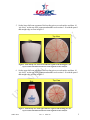
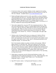
EQUIPMENT SPECIFICATIONS &
CERTIFICATION
Purpose: To measure the pin coating thickness of non-AMF pins.
Materials:
•
•
•
•
•
•
•
•
•
Keyence digital microscope, VHX-100K series
Keyence digital microscope lens, VH-Z25
4 cut pin segments: head, neck, ball zone, and base (SOP-PIN-13)
Keyence digital microscope User’s Manual
Pencil
Straight Edge
Data worksheet
Inkpad
Isopropyl alcohol (IPA)
Procedure:
1. Obtain 4 pin segments and section off each according to steps 2-5.
2. Rub each pin segment on an inkpad, darkening the wood so that it may be in greater
contrast with the plastic coating.
3. Moisten a Kimwipe with IPA and lightly rub the plastic coating to remove any excess
ink from the pin segment.
4. Set the base segment of the bowling pin on a work surface and draw 10 “pie slices”
on the top of the segment and number each section 1-10 with the pencil and straight
edge as seen in figure 1.
Top View
10
9
1
8
Side
Vi
7
2
3
6
4
5
Figure 1 - Side and top view of base segment of the bowling pin. The top view
shows the 10 divisions drawn on the segment for later analysis.
SOP-LAB-4
Rev: 4 05/04/10
1
EQUIPMENT SPECIFICATIONS &
CERTIFICATION
5. Set the lower ball zone segment of the bowling pin on a work surface and draw 10
“pie slices” on the top of the segment and number each section 1-10 with the pencil
and straight edge as seen in figure 2.
Top View
Side
Vi
9
10
8
1
7
2
6
3
5
4
Figure 2 - Side and top view of the lower ball zone segment of the bowling pin. The
top view shows the 10 divisions drawn on the segment for later analysis.
6. Set the upper ball zone segment of the bowling pin on a work surface and draw 10
“pie slices” on the top of the segment and number each section 1-10 with the pencil
and straight edge as seen in figure 3.
Top View
Side
Vi
Figure 3 - Side and top view of the upper ball zone segment of the bowling pin. The
top view shows the 10 divisions drawn on the segment for later analysis.
SOP-LAB-4
Rev: 4 05/04/10
2
EQUIPMENT SPECIFICATIONS &
CERTIFICATION
7. Set the neck segment of the bowling pin on a work surface and draw 10 “pie slices”
on the top of the segment and number each section 1-10 with the pencil and straight
edge as seen in figure 4.
Top View
Side
Vi
9
10
8
1
2
7
3
6
5
4
Figure 4 - Side and top view of the neck segment of the bowling pin. The
top view shows the 10 divisions drawn on the segment.
8. Power up the microscope.
9. Place a white business card on the stage.
a. Focus in on a letter.
b. Flip the card over to its white backside.
c. Touch the “White Balance” key on the front panel of the CPU.
10. Adjust coarse adjustment knob to a magnification of 25 and lower the stage.
11. Calibrate the lens.
a. Select Lens from the main toolbar (located in the bottom right-hand corner of
the screen).
i. Select the lens power; in this case, click 25
ii. Click on “Calibration”
iii. Check to be sure lens power is set to x25 (on screen)
iv. Verify that the units are set to inches and set the number of decimal
points to three.
v. Select OK to save changes and continue.
12. Select Menu from the main toolbar.
SOP-LAB-4
Rev: 4 05/04/10
3
EQUIPMENT SPECIFICATIONS &
CERTIFICATION
13. From the menu bar at the top left-hand corner of the screen, select the Measure
command.
14. Verify that the lens power is set correctly at the bottom of the Measure Tool Window
screen and select the “2-points” measuring option.
15. Place pin segment on the stage with the section labeled #1 directly beneath the lens.
16. Focus in on the pin coating (outer edge of the segment) using the fine adjustment
knob.
17. When necessary, adjust the lighting with the light control knob located on the front
panel of the CPU.
18. Using the mouse, click on the inner edge of the pin coating, drag to the outer edge
and click the mouse one more time in order to save the measurement.
a. Verify that the units are set to inches in the Measure Result Window.
b. Record measurement on worksheet.
19. Repeat steps 13-16 for each numbered section on every segment.
20. Save all data from pin section.
a. Resize the Measure Result Window so that it shows all measurements taken
for pin segment.
b. Select “Save as CSV.”
c. Using the mouse, move the soft keyboard window to the side (it will open up
directly on top of the Save window).
d. Type in file name and select (create if necessary) appropriate folder.
21. Repeat steps 13-18 for each of the four segments of the pin.
SOP-LAB-4
Rev: 4 05/04/10
4