1
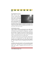
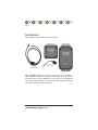
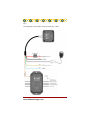
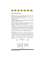
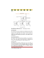
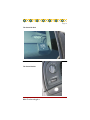
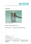
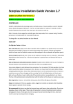
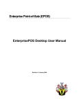
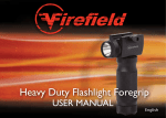
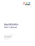
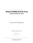
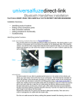
Installation and User Guide
Included:
• Installation Instructions
• Operation Instructions
Page 2
Table of Contents
System Description
3
Installation
5
Wiring Diagram
7
Wire Descriptions
8
Adding Additional Relays
8
Installation Reference: Mounting locations
9
Preferred Mounting Location Photos
10
Operation
11
NOTICE
The Night Ops system is intended for use by Law Enforcement
and Governmental agencies ONLY. We strongly suggest that
you abide by local state and federal laws/regulations in regards
to the use of this product. 836 Technologies will not be held
liable for injuries and/or damages resulting from use of this product. For further information or questions, please contact us.
836 Technologies
Page 3
System Overview
Police Officers know the
importance of approaching calls
in-progress without being detected.
This is done for officer safety
reasons and to catch criminals.
During hours of darkness, officers
are able to turn off their headlights
and use that darkness for a
tactical advantage when making
their approach. That is, until they
tap their brakes and the entire street is illuminated by the red glow of the
brake lights. The Night Ops Blackout System by 836 Technologies is the
solution by temporarily and correctly disabling the brake lights on your
patrol vehicle with a touch of a button.
Vehicle Blackout Systems
Years ago blackout circuits were common place in Law Enforcement
vehicles. Most were simple improvised toggle switch circuits, which
interrupted the power to the brake lights when turned on. An LED was
often employed, mounted somewhere on the dashboard to indicate that
the brake lights were disabled. The intensity of the LED was turned
down, so as not to light up the interior of the vehicle during night
operation. The toned down LED was barely visible during daylight
hours. If not toned down, the LED was too bright at night.
Another problem with “home brew” blackout systems was the way the
installer chose to disrupt the brake lights. The installer would often insert
the switch so as to interrupt power at the brake pedal. This caused
problems with the PARK interlock on the steering column, making it
impossible to get the vehicle out of park when activated. It also disrupted
the vehicles computer system by not indicating when the driver was
braking.
Unfortunately these systems, which were often left on during daylight
hours and often installed improperly, led to the unfortunate downfall of
blackout systems. Departments saw this valuable patrol technique as a
liability and eventually it disappeared from the tool belt of Law
Enforcement.
www.836technologies.com
Page 4
Why the Night Ops system?
The Night Ops system from 836 Technologies provides officers with
the ability to safely and effectively disable the brake lights and back-up
lights of their patrol vehicles. The system is automated and cannot be
activated unless conditions are right. There is no way for the system to
operate unless the driver specifically wants it to. The system can be
installed into nearly any vehicle.
System Advantages
Allows for a tactical approach to calls.
Apprehend more criminals.
Greatly reduces the risk of liability for your department.
Cost effective for your entire fleet.
Easy to install.
Reduce Departmental Liability
System will not activate in daylight.
Automatic deactivation once the headlights are turned on.
Automatic deactivation 30 seconds after the engine is turned off.
Three intensity level LED indicator and audible alerts notify you of
system status.
Fail safe design returns the system to normal (lights on) mode in the
event of failure.
No risk of affecting braking performance or PARK lock.
836 Technologies
Page 5
Installation:
The Night Ops system is made up of four (4) parts:
The Controller Unit is the heart of the system. It contains a
microcontroller which handles all system automation. This unit needs to
be mounted on the vehicle dashboard where it will have an unimpeded
view of the ambient daylight. A female CAT5 type modular port allows
for a quick connection to the wire harness.
www.836technologies.com
Page 6
The Interrupter Unit is designed to be mounted out of sight; typically
in the trunk of the vehicle. It contains a normally closed 4 pole relay
which is used to disconnect the power to four lighting circuits (Left
Brake light / Right Brake Light / Rear Window Brake Light / Back-up
Lights). The four circuits (A,B,C,D) are flexible and can be used any
order desired. The maximum current through each circuit should not
exceed 2 Amperes. The Interrupter Unit is NOT weatherproof! Be sure to
mount it in the trunk or cab of the vehicle.
The Control Switch is a highly durable illuminated momentary push
switch. It will illuminate in blue light to announce the status of the
system. The light intensity is controlled automatically by the controller
unit and is based on the ambient light levels. This switch can be
mounted anywhere inside the vehicle. However, in a Police Interceptor
(Crown Vic) it is best suited to be mounted in the dashboard directly
under the headlight switch. A mounting hole must be drilled for the
switch:
Use a 5/8” drill bit
The additional use of an adhesive is recommended to secure the Control
Switch. Silicone or hot melt glue will suffice if necessary.
The Wire Harness connects all the components together. It contains an
in-line 2 Amp fuse which protects the complete system.
836 Technologies
Page 7
The Night Ops system installs easily into nearly any vehicle.
www.836technologies.com
Page 8
Wire Descriptions:
RED: Positive power source. Connect to the positive side of the 12 Vdc
battery. This line should always be connected (uninterrupted). The wire
contains an in-line 2 Amp ATC blade type fuse.
BLACK: Main system ground. Be sure this is securely attached the
vehicles ground plain.
YELLOW: Attach to the vehicle’s accessory circuit. This wire should
have +12 Vdc applied whenever the ignition key is on. This wire is a
sensing wire and draws less that 1 mA.
BLUE: Attach this wire to the vehicle’s parking light circuit. It should
have +12 Vdc applied any time the vehicle’s parking lights are turned on.
This wire is a sensing wire and draws less that 1 mA.
ORANGE: Control Wire. This is the only wire that connects the
Interrupter Unit to the Controller Unit. This wire will be energized to
+12 Vdc when the Night Ops system is activated. It is capable of
supplying up to 1.0 Amp. An additional relay may be attached to drive
(or disrupt) additional circuits as long as the relay is equipped with a
dampening (clamp) diode. To drive multiple relays, drive them off a
primary relay. Refer to diagrams below for adding additional relays.
OEM Wiring: The Interrupter Unit has four pass-through circuits
labeled A through B. These circuits are normally closed and will open
when the system is activated. It will be necessary to locate the vehicle’s
rear light wiring harness and identify the wires which need to be
interrupted. This manual does not attempt to identify every vehicle
manufacture’s wire location and color scheme. You should attempt to
locate these wires and disrupt them as close to the actual lamp as
possible.
Driving an additional relay
836 Technologies
Page 9
Installation Reference - Mounting Locations
Controller Unit
The Controller Unit must be installed on the dashboard of the vehicle.
The unit contains a small light intensity detector which should always be
exposed to the ambient light. The Controller Unit also contains an
audible buzzer, which sounds to alert status. The Controller unit is
supplied with double sided sticky tape, which is used to adhere the unit to
the dashboard.
Control Switch (button)
The Control Switch is connected to the wire harness via a 3 pin mini inline connector. The switch can be mounted anywhere within the driver’s
reach. The switch contains a blue LED, which is controlled by the
Controller Unit and will illuminate at 3 different intensity levels.
Interrupter Unit
The Interrupter Unit should be mounted in the rear of the vehicle, as
close to the actual lights as possible. The orange control wire is extended
to reach the interrupter unit. Care should be taken to tie down all
wires connected to the Interrupter Unit as to minimize vibration
stress on the internal connection pins.
www.836technologies.com
Page 10
The Controller Unit
The Control Switch
836 Technologies
Page 11
Operation:
To activate the system (disable the rear brake lights and backup lights)
several conditions must first be met:
1) It must be dark outside. If the button is pressed while light
outside, the button will flash several times (high brightness) and the
control unit will beep several times. It will not activate.
2) The vehicle’s lights must be off. If the button is pressed while
the lights are on, the button will flash several times (low brightness
if dark outside) and the control unit will beep several times. It will
not activate.
If the driver presses the control button while it is dark outside and the
vehicle’s lights are off, then the system will beep and activate. The
control button will illuminate at a very low level and periodically flash
off to remind the driver that it is on. Pressing the button again will
deactivate the system.
If the driver turns on the lights while the system is activated, the system
will beep once and deactivate.
If the system is activate and the ignition key gets switched off, the
system will wait 30 seconds then deactivate. It can be switched back on
while the key is still off if necessary.
The control button will illuminate (blue light) at three different intensity
levels depending upon the outside ambient light levels.
www.836technologies.com
2715 W. Kettleman Lane
Lodi, CA. 95242
Phone: 209-559-8879
Technical Assistance: 209-366-3242
Fax: 916-687-0913
E-mail: [email protected]