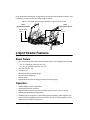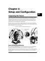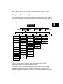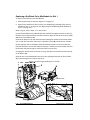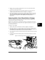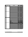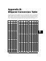
1
User Manual
© High End Systems, Inc. 2003, All Rights Reserved
Information and specifications in this document are subject to change without notice.
High End Systems, Inc. assumes no responsibility or liability for any errors or
inaccuracies that may appear in this manual.
Trademarks used in this text: Lightwave Research, High End Systems, Studio Color,
Studio Spot, Technobeam, Intellabeam, Dataflash AF1000, HOG III, and LithoPatterns are
registered trademarks; and HandShake, x.Spot, TalkBack, Studio Spot, Lithomotion,
ZoomTrack, Internal Effects, Light Burst, Electronic Strobe, the High End Systems globe
logo and the Hog logo are trademarks of High End Systems, Inc. or High End Systems
Europe Ltd. Belden is a registered trademark of Belden, Inc. Philips is a registered
trademark of Philips Lighting Company. Fram is a registered trademark of Allied Signal.
ETL and C-ETL are registered trademarks of Intertek Testing Services.
Other trademarks and trade names may be used in this document to refer to either the
entities claiming the marks and names or their products. High End Systems disclaims any
proprietary interest in trademarks and trade names owned by others.
x.Spot®Xtreme User Manual
P/N 60600222 Version 1.0 April, 2003
Printed in the USA
S.G.
x.Spot®Xtreme User Manual
i
Contacting High End Systems®
US and the Americas
Sales Department:
High End Systems, Inc.
2217 West Braker Lane
Austin, TX 78758 USA
voice:
512.836.2242
fax:
512.837.5290
Customer Service:
High End Systems, Inc.
2227 West Braker Lane
Austin, TX 78758 USA
voice:
800.890.8989
24-hour fax:
512.834.9195
24-hour voice mail: 512.837.3063 or 800.890.8989
U.S. New York
High End Systems, Inc. New York
311 W. 43rd Street, Ste 400
New York, NY 10036
voice:
210.957.6840
fax:
212.957.4466
U.S. Los Angeles:
High End Systems, Inc.
8200 Haskell Avenue
Van Nuys, CA 91406 US
voice:
818.947.0550
fax:
818.908.8975
U.S. Orlando:
voice
fax:
407.296.3359
407.523.9092
Canada:
voice:
fax:
416.335.8537
416.335.8539
United Kingdom:
High End Systems Europe LTD.
53 Northfield Road
London W13
voice:
+44 20.8579.5665
fax:
+44 20.8579.8469
Germany
voice
fax:
Singapore:
High End Systems Singapore Pte. Ltd.
1 Tannery Road 06-05
Cencon 1
Singapore 1334
voice:
+65 6742 8266
FAX:
+65 6743 9322
World Wide Web:
http://www.highend.com
ii
+49 5331 9925-91
+49 5331 9925-92
x.Spot®Xtreme User Manual
Declaration of Conformity
according to ISO/IEC Guide 22 and
EN45104
Manufacturer’s name:
High End Systems, Inc.
Distributor’s name:
Distributor’s address:
High End Systems, Inc.
2217 West Braker Lane
Austin, Texas 78758 USA
Declares that the product
Product Name:
Product Number:
Product Options:
x.Spot®Xtreme
All
All
conforms to the following EEC directives:
73/23/EEC, as amended by 93/68/EEC
89/336/EEC, as amended by 92/31/EEC and 93/68/EEC
Equipment referred to in this declaration of conformity was first manufactured in compliance with the following standards in 2001:
Safety:
EN 60598-1: 1997/A1:1998
EN 60598-2-17: 1989/A2:1991
EMC:
EN 55022+A1+A2: 1987 Class A
EN55024: 1998
EN61000-4-2: 1995 Level 3, Cls2
EN61000-4-3: 1995 Level 2
EN61000-4-4: 1995 Level 2
EN61000-4-5: 1995 Level 2
EN61000-4-6: 1996 Level 2
EN61000-4-11: 1994
EN61000-3-2: 1995 Class A
USA, Wednesday, April 23, 2003
Kenneth Stuart Hansen, Compliance Engineer
x.Spot®Xtreme User Manual
iii
Product Modification Warning
High End Systems products are designed and manufactured to meet the requirements of
United States and International safety regulations. Modifications to the product could
affect safety and render the product non-compliant to relevant safety standards.
Mise En Garde Contre La Modification Du Produit
Les produits High End Systems sont conçus et fabriqués conformément aux exigences
des règlements internationaux de sécurité. Toute modification du produit peut entraîner
sa non conformité aux normes de sécurité en vigueur.
Produktmodifikationswarnung
Design und Herstellung von High End Systems entsprechen den Anforderungen der U.S.
Amerikanischen und internationalen Sicherheitsvorschriften. Abänderungen dieses
Produktes können dessen Sicherheit beeinträchtigen und unter Umständen gegen die
diesbezüglichen Sicherheitsnormen verstoßen.
Avvertenza Sulla Modifica Del Prodotto
I prodotti di High End Systems sono stati progettati e fabbricati per soddisfare i requisiti
delle normative di sicurezza statunitensi ed internazionali. Qualsiasi modifica al prodotto
potrebbe pregiudicare la sicurezza e rendere il prodotto non conforme agli standard di
sicurezza pertinenti.
Advertencia De Modificación Del Producto
Los productos de High End Systems están diseñados y fabricados para cumplir los
requisitos de las reglamentaciones de seguridad de los Estados Unidos e internacionales.
Las modificaciones al producto podrían afectar la seguridad y dejar al producto fuera de
conformidad con las normas de seguridad relevantes.
FCC Information
This equipment has been tested and found to comply with the limits for a Class A digital
device, pursuant to part 15 of the FCC rules. These limits are designed to provide
reasonable protection against harmful interference when the equipment is operated in a
commercial environment. This equipment generates, uses, and can radiate radio
frequency energy and, if not installed and used in accordance with the instruction
manual, may cause harmful interference to radio communications. Operation of this
equipment in a residential area is likely to cause harmful interference, in which case the
user will be required to correct the interference at his own expense.
iv
x.Spot®Xtreme User Manual
Important Safety Information
Instructions pertaining to continued protection against fire, electric shock, exposure to
excessive ultraviolet (UV) radiation, and injury to persons are found in Appendix C.
Please read all instructions prior to assembling, mounting, and operating this equipment.
Important: Informations De Sécurité
Les instructions se rapportant à la protection permanente contre les incendies,
l’électrocution, l’exposition à un rayonnement ultraviolet (UV) excessif et aux blessures
corporelles se trouvent dans l’Annexe C.
Veuillez lire toutes les instructions avant d’assembler, de monter ou d’utiliser cet
équipement.
Wichtige Sicherheitshinweise
Sicherheitsanleitungen zum Schutz gegen Feuer, elektrischen Schlag, übermäßige UVStrahlung und Verletzung von Personen finden Sie in Anhang C.
Vor der Montage, dem Zusammenbau und der Intbetriebnahme dieses Geräts alle
Anleitungen sorgfältig durchlesen.
Informazioni Importanti Di Sicurezza
Le istruzioni sulla protezione da incendi, folgorazione, esposizione eccessiva a raggi
ultravioletti (UV) e infortuni sono contenute nell’appendice C.
Si prega di leggere tutte le istruzioni prima di assemblare, montare e azionare
l’apparecchiatura.
Informacion Importante De Seguridad
En el Apéndice C se encuentran instrucciones sobre protección continua contra incendios,
descarga eléctrica, exposición excesiva a radiación ultravioleta (UV) y lesiones
personales.
Lea, por favor, todas las instrucciones antes del ensamblaje, montaje y operación de este
equipo.
x.Spot®Xtreme User Manual
v
Symbols
The following international caution and warning symbols appear in margins
throughout this manual to highlight messages.
Caution: This symbol appears adjacent to Caution messages. Not heeding
these messages could result in personal injury and/or damage to
equipment.
Warning: This symbol appears adjacent to high voltage warning messages.
Not heeding these messages could result in serious personal
injury.
This symbol indicates that a fire hazard is present. Not heeding these
messages could result in serious personal injury.
This symbol indicates that eye protection is required.
This symbol indicates an explosion hazard.
This symbol indicates the minimum distance to a lighted object, which in
this case, is 1 meter.
This symbol indicates a hot surface.
This symbol indicates that an object not be mounted on a flammable
surface
vi
x.Spot®Xtreme User Manual
Warranty Information
Limited Warranty
Unless otherwise stated, your product is covered by a two year parts and labor limited
warranty. Dichroic filters are not guaranteed against breakage or scratches to coating. It
is the owner’s responsibility to furnish receipts or invoices for verification of purchase,
date, and dealer or distributor. If purchase date cannot be provided, date of manufacture
will be used to determine warranty period.
Returning an Item Under Warranty for Repair
It is necessary to obtain a Return Material Authorization (RMA) number from your dealer
or point of purchase BEFORE any units are returned for repair. The manufacturer will
make the final determination as to whether or not the unit is covered by warranty. Lamps
are covered by the lamp manufacturer’s warranty.
Any Product unit or parts returned to High End Systems must be packaged in a suitable
manner to ensure the protection of such Product unit or parts, and such package shall be
clearly and prominently marked to indicate that the package contains returned Product
units or parts and with an RMA number. Accompany all returned Product units or parts
with a written explanation of the alleged problem or malfunction. Ship returned Product
units or parts to: 2227 West Braker Lane, Austin, TX 78758 USA.
Note: Freight Damage Claims are invalid for fixtures shipped in non-factory boxes
and packing materials.
Freight
All shipping will be paid by the purchaser. Items under warranty shall have return
shipping paid by the manufacturer only in the Continental United States. Under no
circumstances will freight collect shipments be accepted. Prepaid shipping does not
include rush expediting such as air freight. Air freight can be sent customer collect in the
Continental United States.
REPAIR OR REPLACEMENT AS PROVIDED FOR UNDER THIS WARRANTY IS THE
EXCLUSIVE REMEDY OF THE CONSUMER. HIGH END SYSTEMS, INC. MAKES NO
WARRANTIES, EXPRESS OR IMPLIED, WITH RESPECT TO ANY PRODUCT, AND
HIGH END SPECIFICALLY DISCLAIMS ANY WARRANTY OF MERCHANTABILITY OR
FITNESS FOR A PARTICULAR PURPOSE. HIGH END SHALL NOT BE LIABLE FOR
ANY INDIRECT, INCIDENTAL OR CONSEQUENTIAL DAMAGE, INCLUDING LOST
PROFITS, SUSTAINED OR INCURRED IN CONNECTION WITH ANY PRODUCT OR
CAUSED BY PRODUCT DEFECTS OR THE PARTIAL OR TOTAL FAILURE OF ANY
PRODUCT REGARDLESS OF THE FORM OF ACTION, WHETHER IN CONTRACT,
TORT (INCLUDING NEGLIGENCE), STRICT LIABILITY OR OTHERWISE, AND
WHETHER OR NOT SUCH DAMAGE WAS FORESEEN OR UNFORESEEN.
Warranty is void if the product is misused, damaged, modified in any way, or for
unauthorized repairs or parts. This warranty gives you specific legal rights, and you may
also have other rights which vary from state to state.
x.Spot®Xtreme User Manual
vii
viii
x.Spot®Xtreme User Manual
Table of Contents
Contacting High End Systems® .................................................................................................... ii
Product Modification Warning ......................................................................................................iv
FCC Information .............................................................................................................................iv
Important Safety Information .........................................................................................................v
Symbols ...........................................................................................................................................vi
Warranty Information....................................................................................................................vii
Chapter 1:
Features and Specifications
Standard Configuration ............................................................................................................... 1-1
x.Spot®Xtreme Features .............................................................................................................. 1-2
Basic Fixture.......................................................................................................................... 1-2
Operation ............................................................................................................................... 1-2
Construction .......................................................................................................................... 1-3
Module Features ................................................................................................................... 1-3
Six-Wheel Color Mixing Module .................................................................................. 1-3
Dual Rotating Gobo Module ......................................................................................... 1-3
Rotating Gobo and Iris Module..................................................................................... 1-3
Optional Accessories ................................................................................................................... 1-4
Specifications ............................................................................................................................... 1-5
Physical Specifications ......................................................................................................... 1-5
Electrical Specifications ....................................................................................................... 1-6
Environmental Specifications .............................................................................................. 1-6
Dichroic, Litho, and Effect Specifications........................................................................... 1-6
Lamp Specifications.............................................................................................................. 1-6
Lens Specifications ............................................................................................................... 1-7
Cable and Connector Specifications.................................................................................... 1-7
Chapter 2:
Setup and Configuration
Unpacking the Fixture................................................................................................................. 2-1
Save All Shipping Materials ................................................................................................. 2-1
Installing a Power Cord Cap ....................................................................................................... 2-2
Installing a Line Cord Cap - U.K. Only................................................................................ 2-2
Vatic Fitter Heads Information - Danmark ......................................................................... 2-2
Mounting the Fixture................................................................................................................... 2-3
Mounting the Fixture Upright.............................................................................................. 2-3
Truss Mounting ..................................................................................................................... 2-3
Safety Cable ................................................................................................................... 2-6
Fixture Clamps............................................................................................................... 2-6
Suggested Truss Mounting Procedure ................................................................................ 2-6
Linking the Fixtures..................................................................................................................... 2-7
Data Cabling and Connectors .............................................................................................. 2-7
x.Spot®Xtreme User Manual
ix
DMX Data Cables .......................................................................................................... 2-7
Cable Connectors........................................................................................................... 2-7
Setting up the Link ............................................................................................................... 2-8
Constructing a Terminator ................................................................................................... 2-9
Powering On the Fixture ........................................................................................................... 2-10
Homing the Fixture.................................................................................................................... 2-10
Viewing the Display Panel ................................................................................................. 2-10
Fixture Software Version ............................................................................................ 2-10
Fixture Configuration Type......................................................................................... 2-10
DMX Start Channel ..................................................................................................... 2-11
Error Message Display ................................................................................................ 2-11
Verifying and Uploading Fixture Software .............................................................................. 2-11
Setting the DMX Start Channel ................................................................................................ 2-12
Shutting Down the Fixture........................................................................................................ 2-13
Chapter 3:
Fixture Operation
Direct x.SpotXtreme Menu System Access ............................................................................... 3-1
TalkBack™ Support for Remote Access ..................................................................................... 3-1
Navigating the Menu System ...................................................................................................... 3-2
The x.SpotXtreme Display ................................................................................................... 3-2
Navigational Basics............................................................................................................... 3-3
Display in Menu Locked Mode ............................................................................................ 3-3
Fixture Software Version .............................................................................................. 3-3
Fixture Configuration Type........................................................................................... 3-3
DMX Start Channel ....................................................................................................... 3-3
Error Message Display .................................................................................................. 3-4
Unlocking the Menu System ................................................................................................ 3-4
Exiting the Menu System ..................................................................................................... 3-4
The Menu System Structure ................................................................................................ 3-4
DMX Address Menu .................................................................................................................... 3-6
Setting DMX Start Channel ................................................................................................. 3-6
Determining DMX Start Channel Assignment ................................................................... 3-6
Onboard Presets Menu ................................................................................................................ 3-8
Playback Mode Menu ........................................................................................................... 3-8
Edit Scene ## Menu............................................................................................................. 3-8
Editing Scene Parameters by Slot ................................................................................ 3-9
Adding Timing to a Scene ........................................................................................... 3-11
Zero Scene.................................................................................................................... 3-13
Copy Scene Menu ............................................................................................................... 3-13
Capture DMX to Scene....................................................................................................... 3-14
Default Presets .................................................................................................................... 3-14
Send Presets to Other Fixtures .......................................................................................... 3-15
Set Parameters Menu ................................................................................................................ 3-16
Factory Default Settings..................................................................................................... 3-16
x
x.Spot®Xtreme User Manual
Pan/Tilt Swap ...................................................................................................................... 3-16
Pan Invert ............................................................................................................................ 3-17
Tilt Invert ............................................................................................................................. 3-17
Display Invert ...................................................................................................................... 3-18
Display Level ....................................................................................................................... 3-18
Lamp Life Limit ................................................................................................................... 3-19
Data Loss Timeout .............................................................................................................. 3-19
Fixture Mode Menu .................................................................................................................. 3-20
Module Configuration Menu.............................................................................................. 3-20
Select User Mode ................................................................................................................ 3-20
Protocol Mode ..................................................................................................................... 3-21
Copy Users .......................................................................................................................... 3-21
Crossloading Fixture Software .......................................................................................... 3-21
Test Options Menu..................................................................................................................... 3-23
Homing the Fixture............................................................................................................. 3-23
Lamp State........................................................................................................................... 3-23
Copying the Boot Code....................................................................................................... 3-23
Self Test Menu .................................................................................................................... 3-24
Information Menu ..................................................................................................................... 3-25
Sensor Status Menu............................................................................................................ 3-25
Unique Number................................................................................................................... 3-25
DMX Values Menu.............................................................................................................. 3-25
Temperatures Menu............................................................................................................ 3-26
Fixture Hours ...................................................................................................................... 3-27
Fixture Hours Reset ............................................................................................................ 3-27
Lamp Hours ......................................................................................................................... 3-27
Lamp Strikes ....................................................................................................................... 3-27
Lamp HR/Strike Reset ........................................................................................................ 3-27
Lamp Status......................................................................................................................... 3-28
Software Version................................................................................................................. 3-28
Display Errors ..................................................................................................................... 3-28
Channels Needed ................................................................................................................ 3-28
Next DMX Channel ............................................................................................................ 3-28
Chapter 4:
DMX Programming
x.SpotXtreme DMX Protocol ...................................................................................................... 4-1
DMX Programming Options ....................................................................................................... 4-2
Show Creation with a DMX Controller ............................................................................... 4-2
Show Creation with Onboard Preset Menu ........................................................................ 4-2
Creating a Loop.............................................................................................................. 4-2
Playing Back a Loop ...................................................................................................... 4-3
Synchronizing Preset Playback .................................................................................... 4-3
DMX Parameter Descriptions ..................................................................................................... 4-4
Basic Fixture Parameters ..................................................................................................... 4-4
x.Spot®Xtreme User Manual
xi
Pan and Tilt .................................................................................................................... 4-4
Lamp Function ............................................................................................................... 4-4
Shutter ............................................................................................................................ 4-5
Dim.................................................................................................................................. 4-6
Frost ................................................................................................................................ 4-7
Focus Control and Focus............................................................................................... 4-7
Zoom ............................................................................................................................... 4-7
MSpeed (Motor Speed) ................................................................................................. 4-8
Macro .............................................................................................................................. 4-8
Control ............................................................................................................................ 4-9
Six-Wheel Color Mixing Module Parameters................................................................... 4-10
Static Color Function................................................................................................... 4-10
Static Color Position .................................................................................................... 4-11
Color Mix Function...................................................................................................... 4-11
Cyan, Magenta, and Yellow ........................................................................................ 4-12
CTO and CTB ............................................................................................................... 4-12
Dual Rotating Gobos Module Parameters......................................................................... 4-13
Gobo Function.............................................................................................................. 4-14
Gobo Position ............................................................................................................... 4-14
Gobo Rotate Function.................................................................................................. 4-14
Gobo Rotate Coarse/Fine............................................................................................. 4-14
Rotating Gobo and Iris Module Parameters ..................................................................... 4-16
Gobo 2 Function........................................................................................................... 4-16
Gobo 2 Position ............................................................................................................ 4-17
Gobo 2 Rotate Function............................................................................................... 4-17
Gobo 2 Rotate Coarse/Fine.......................................................................................... 4-17
Iris ................................................................................................................................. 4-18
Chapter 5:
General Maintenance
Replacing Parts ............................................................................................................................ 5-2
Replacing Fuses .................................................................................................................... 5-2
Replacing the Lamp .............................................................................................................. 5-4
Optimizing the Lamp ............................................................................................................ 5-5
Replacing a Driver Board ..................................................................................................... 5-6
Replacing Modules................................................................................................................ 5-7
Before Beginning .......................................................................................................... 5-7
Replacing a Rotating Gobo and Iris Module in Slot 3 ................................................. 5-8
Replacing a Dual Rotating Gobo Module in Slot 2...................................................... 5-9
Replacing a Six-Wheel Color Mix Module for Slot 1 ................................................ 5-10
Replacing Static Color Wheel Dichroic Wedges............................................................... 5-11
Replacing Lithopatterns® and Effects Glass .................................................................... 5-12
Replacing Static Lithopatterns®................................................................................. 5-14
Cleaning the Glass Components ............................................................................................... 5-15
xii
x.Spot®Xtreme User Manual
Chapter 6:
Troubleshooting
LED States .................................................................................................................................... 6-1
Error Message Troubleshooting ................................................................................................. 6-2
Display Error Messages............................................................................................................... 6-3
Appendix A: x.Spot®Xtreme DMX Protocol
Appendix B: MSpeed Conversion Table
Appendix C: Safety Information
Appendix D:: x.Spot®Xtreme Menu Map
Navigational Basics......................................................................................................................D-1
Level 1 Menus ..............................................................................................................................D-1
DMX Address Menu .............................................................................................................D-2
Onboard Presets Menu .........................................................................................................D-2
Set Parameters Menu .........................................................................................................D-15
Fixture Mode Menu ............................................................................................................D-16
Test Options Menu..............................................................................................................D-17
Information Menu ...............................................................................................................D-18
x.Spot®Xtreme User Manual
xiii
xiv
x.Spot®Xtreme User Manual
List of Figures
Figure 1-1 x.SpotXtreme Fixture Components ........................................................1-1
Figure 1-2 Module Interleaving in Standard x.Spot®Xtreme fixture ...................1-2
Figure 1-3 x-Spot Dimensions ...................................................................................1-5
Figure 2-1
Figure 2-2
Figure 2-3
Figure 2-4
Figure 2-5
Figure 2-6
Figure 2-7
Removing and replacing the bezel .........................................................2-1
Removing handles and side wings ..........................................................2-3
Baseplate configuration for standard truss sizes ..................................2-5
XLR 5-pin connector ................................................................................2-8
Linking x.SpotXtreme fixtures ...............................................................2-9
Data cable terminator ..............................................................................2-9
The x.SpotXtreme menu system navigation buttons ..........................2-12
Figure 3-1
Figure 3-2
Figure 3-3
Figure 3-4
Figure 3-5
Front panel display ..................................................................................3-2
x.SpotXtreme Menu System Overview ..................................................3-5
Edit Scene Menu Options in Standard x.SpotXtreme fixture ..............3-9
Assigning timing to a scene ..................................................................3-12
Automatic Display Invert feature. ........................................................3-18
Figure 4-1
Figure 4-2
Figure 4-3
Figure 4-4
Figure 4-5
Figure 4-6
Synchronized Playback Example ...........................................................4-3
Example of synchronized playback. .......................................................4-3
x.SpotXtreme color wheel assembly ...................................................4-10
Static Color Wheel positions ................................................................4-11
Wheels in the Dual Rotating Gobos module ........................................4-13
Rotating Gobo 2 Lithopatterns ..............................................................4-16
Figure 5-1 Removing and replacing the bezel .........................................................5-1
Figure 5-2 Locate and access fuses. ..........................................................................5-2
Figure 5-3 Replacing the lamp ..................................................................................5-4
Figure 5-4 Lamp optimization screws ......................................................................5-6
Figure 5-5 Driver board configurations. ...................................................................5-6
Figure 5-6 Replacing a 2-phase driver board. ..........................................................5-7
Figure 5-7 Installing/Replacing Slot 3 Module. ........................................................5-8
Figure 5-8 Installing/Removing Slot 2 Module. .......................................................5-9
Figure 5-9 Removing/Installing Slot 3 module .......................................................5-10
Figure 5-10 Removing the Static Color Wheel. ......................................................5-11
Figure 5-11 Replacing Static Color Wedges ...........................................................5-11
Figure 5-12 Accessing Dichroic wedges in Static Color Wheel. ...........................5-12
Figure 5-13 Replacing a lithopattern or effects glass in a rotating gobo wheel. .5-13
Figure 5-14 Replacing Static lithopatterns. ............................................................5-14
x.Spot®Xtreme User Manual
xv
List of Tables
Table 3-1 Example: Determining DMX Start Channels on a Link ........................3-7
Table 3-2 Module Identification .............................................................................3-20
Table 3-3 Self Test by Slot ......................................................................................3-24
Table
Table
Table
Table
Table
Table
Table
Table
Table
Table
Table
Table
4-1 Parameters for a Standard Configuration x.SpotXtreme Fixture .......4-1
4-2 Lamp Control and Shutter Parameter Settings .....................................4-5
4-3 Frost Setting Descriptions ......................................................................4-7
4-4 Control Setting Descriptions ..................................................................4-9
4-5 Static Color Function Descriptions ......................................................4-10
4-7 Cyan, Magenta, and Yellow Setting Descriptions ...............................4-12
4-6 Color Mix Function Descriptions .........................................................4-12
4-8 Gobo Function Descriptions .................................................................4-14
4-9 Gobo Rotate Functions and Rotate Options ........................................4-15
4-10 Gobo 2 Function Descriptions .............................................................4-16
4-11 Gobo2 Rotate Functions and Available Options ................................4-17
4-12 Iris Setting Descriptions ......................................................................4-18
Table 5-1 Identifying blown fuses .............................................................................5-3
Table 5-2 Fuse replacement ......................................................................................5-3
Table 6-1 LED State ...................................................................................................6-1
xvi
x.Spot®Xtreme User Manual
Chapter 1:
1
Features and Specifications
The x.Spot®Xtreme luminaire integrates multiple advances in automated lighting
technology to give the lighting designer the ultimate hard-edge fixture for
professional applications. The modular design shown in Figure 1-1 includes three
user-configurable slots to allow maximum customization and upgradability.
Standard Configuration
A standard configuration for x.SpotXtreme includes the following modules:
• Slot 1—Six-Wheel Color Mixing
• Slot 2—Dual Rotating Gobos
• Slot 3—Rotating Gobo and Iris
Figure 1-1 x.SpotXtreme Fixture Components
Effects
Gobo1
SLOT 2
Dual Rotating
Gobos Module
LENS ASSEMBLY
SLOT 3
Rotating Gobo
and Iris Module
Iris
Gobo2
LAMP ASSEMBLY
SLOT 1
Six-Wheel Color
Mixing Module
TOP BOX
x.Spot®Xtreme User Manual
Features and Specifications
1-1
In the standard x.SpotXtreme configuration, the wheels of the modules in Slots 2 and
3 interleave to allow for the maximum range of effects.
Figure 1-2 Module Interleaving in Standard x.Spot®Xtreme fixture
Slot 3
Rotating Gobo and Iris
Slot 2
Dual Rotating Gobos
Effects Wheel
Iris
Gobo 1
Gobo 2
x.Spot®Xtreme Features
Basic Fixture
•
Two zoom lens options with constant aperture and focus tracking while zooming:
— 2:1 f1.4 6-element zoom lens (15°–30°)
— 4:1 f2.0 11-element zoom lens (11°–45°)
•
630° Pan and 240° Tilt
•
Variable frost
•
Mechanical and electronic strobe
•
Smooth, linear dimming
•
Remote focus
•
Independent electronic homing for fixture function groups
Operation
•
USITT DMX-512 1990 Compatible
•
ACN-ready Ethernet connector
•
High-resolution optical encoders to monitor position and correct on the fly
•
Onboard programming and playback
•
TalkBack protocol support for automating remote patching, status updates, etc.
•
Large dot matrix display that allows for 2 lines of text and automatically inverts
display based on fixture orientation
1-2
Features and Specifications
x.Spot®Xtreme User Manual
Construction
•
Flicker-free, electronic universal power supply (120–230V)(50-60Hz)
•
Modular construction for easy upgrading and customizing
•
Square base for universal truss mounting
•
Easy head removal with clamshell bezels
•
Ease of maintenance
1
—modularity
—interchangeable driver boards between modules
—minimum metric standard tool set
Module Features
Six-Wheel Color Mixing Module
•
Smooth CMY color mixing
•
Six-position dichroic color wheel with five (5) replaceable color filters plus open
•
Variable Color Temperature Correction (3000°K –7500°K) through the use of CTO
and CTB filters
•
Frost wedges on CTO and CTB filters to implement remote three-level beam
flatness adjustment
Dual Rotating Gobo Module
•
Two Gobo wheels:
— Gobo wheel 1 has seven rotating, indexing Lithopatterns® glass gobos with
stacking capability (plus open)
— Effects Gobo wheel has rotating, indexing glass effects in seven apertures
(plus open)
— Moire and overlay effects capability on two positions of Gobo wheel 1
Rotating Gobo and Iris Module
•
Gobo wheel 2 has seven rotating, indexing Lithopatterns® glass gobos with
stacking capability (plus open)
•
Variable Iris
x.Spot®Xtreme User Manual
Features and Specifications
1-3
Optional Accessories
The x.SpotXtreme optional accessories available from your High End Systems
dealer/distributor are listed in the table below. For more information about optional
accessories, contact either your High End Systems dealer/distributor, High End
System Sales, or visit the High End Systems Web site at www.highend.com. For
additional contact information, see “Contacting High End Systems®” on page ii.
Part Description
Replacement MSR700-SA lamp
Color wheel dichroic filters
Lithopatterns
Effect Glass
HandShake Controller
HOG III lighting console
Heavy duty 5-pin XLR cable (10’)
Heavy duty 5-pin XLR cable (25’)
Heavy duty 5-pin XLR cable (50’)
Heavy duty 5-pin XLR cable (100’)
Male 5-pin XLR terminator
Galvanized safety cable
Cheeseborough clamp
Lightwave Research Upload Dongle
Center-hole mounting brackets
Road case for x.SpotXtreme fixtures
Lithomotion module
Framing module
Part Number
55030054
See Note
See Note
See Note
10020001
61020001
55050017
55050018
55050019
55050020
90404039
12040001
55040014
26040002
80430080
46070001
46040001
46040002
Note: Call High End Systems for information on standard or custom dichroic
color filters, lithopatterns and effect glass.
1-4
Features and Specifications
x.Spot®Xtreme User Manual
Specifications
1
Physical Specifications
Height: 814.5mm (32.0 in)
Width:
521mm (20.6 in)
Depth:
520.8mm (20.5in)
Weight: 31.8kg (70lb)
Figure 1-3 x-Spot Dimensions
521mm
(20.5in)
254mm
(10.0in)
470mm
(18.5in)
260mm
(10.25in
343mm
(13.5in)
172mm
(6.75in)
235mm
(9.25in)
523mm
(20.6in)
470mm
(18.5in)
142mm
(5.6in)
426mm
(16.8in)
178mm
(7.0in)
367mm
(14.4in)
814mm
(32.0in)
125mm
(4.9in)
533mm
(21in)
140mm
(5.5in)
557mm
(21.9in)
472mm
(18.6in)
413mm
(16.25in
x.Spot®Xtreme User Manual
Features and Specifications
1-5
Electrical Specifications
Warning:
Class 1 equipment - This equipment must be earthed.
Selectable voltages: Universal Input from 120–230 VAC, (50–60Hz)
Rated power:
1200 W
Fuses:
Motor power supply output: 2.5A, 250V slow blow only.
2- and 3-phase driver boards: 2.5A, 125 V, Slow Blow SMF
Environmental Specifications
Maximum ambient temperature, (Ta): 50° C (122°F)
Maximum exterior surface temperature: 130° C (266°F)
Minimum distance to flammable objects: 1m (3.28ft)
Minimum distance to lighted object: 2m (6.56ft)
2
Do not mount on a flammable surface.
Dichroic, Litho, and Effect Specifications
Dichroic Glass
•
Thickness: 1.8 mm ± 0.25 mm (0.069in ± 0.010in)
LithoPatterns
•
Diameter: 36.45mm ± 0.13 mm (1.435in ± .006)
•
Image area: 31.75mm ± 0.25 mm (1.250in ± 0.010in)
•
Thickness (rotating litho): 1.78mm ± 0.13 mm (.070 in ± .006)
•
Thickness (static litho):1.78mm ± 0.13 mm (.070 in ± .006)
Effect Glass
•
Diameter: 36.45mm ± 0.13 mm (1.435in ± .006)
•
Image area: 31.75mm ± 0.25 mm (1.250in ± .010)
•
Maximum thickness: 3.81mm (.150 in)
Lamp Specifications
1-6
•
Lamp type:
Philips MSR700SA 700W short arc
•
Color temperature:
5600 K
•
Life:
500 hours
Features and Specifications
x.Spot®Xtreme User Manual
Lens Specifications
•
1
2:1 Zoom Option
—Zoom Ratio: 2:1
—Effective focal length: 68mm–138mm
—Full field of view range: 15°–30°
•
4:1 Zoom Option
—Zoom Ratio: 4:1
—Effective focal length: 41mm–165mm
—Full field of view range: 11.8°–45.2°
Cable and Connector Specifications
DMX data cables:
Belden® 9842 or equivalent (meets specifications for EIA RS-485 applications) with
the following characteristics:
•
Two twisted pairs (4-conductors) plus a shield
•
Maximum capacitance between conductors: <15 pF/ft.
•
Maximum capacitance between conductor and shield: 55 pF/ft.
•
Maximum resistance: 20
•
Nominal impedance: 120
/1000 ft.
DMX data connectors:
•
5-pin male and female XLR connectors
DMX data terminators:
•
5-pin male XLR connector with 120 ohm termination resistor
x.Spot®Xtreme User Manual
Features and Specifications
1-7
1-8
Features and Specifications
x.Spot®Xtreme User Manual
Chapter 2:
Setup and Configuration
2
Unpacking the Fixture
Unpack the x.SpotXtreme®Xtreme fixture and verify that it is undamaged. Inspect
both the outside of the fixture for physical damage and the optical assembly for
damage to glass components. To access the optical assembly, loosen the three (3)
captive screws on each side of the fixture head. Remove the bezel by lifting away
from the base and toward the lens, see Figure 2-1.
If there is damage, notify both the shipping agent and the sales agent immediately.
When replacing the bezel, ensure that it is fitted securely in the yoke channel on both
sides of the fixture as shown in Figure 2-1.
Figure 2-1 Removing and replacing the bezel
Captive Screws
Bezel channel in
yoke arm
Save All Shipping Materials
Do not discard the shipping carton and packing materials. The carton and packing
materials are specifically designed to protect the product during transport.
High End Systems® assumes no responsibility for products that are damaged during
transport. Return a product for repair in its original shipping carton and packing
materials.
x.Spot®Xtreme User Manual
Setup and Configuration
2-1
Before sending anything to the factory, call your High End Systems dealer/distributor
for a Return Material Authorization (RMA) number. The factory cannot accept any
goods shipped without an RMA number.
Installing a Power Cord Cap
x.SpotXtreme fixtures are shipped without an attached power cord cap. Different
locations (even within the same country) may require a different power cord cap to
connect the fixture to a power outlet.
Because of the variety of power cord caps used worldwide, High End Systems, Inc.
cannot make specific recommendations for the power cord cap.
Contact a local authority for the type of power cord cap needed. When installing the
power cord cap, note that the cores in the mains lead are colored in accordance with
the following code:
•
green and yellow = earth
•
blue = neutral
•
brown = live
Warning:
Class 1 equipment - This equipment must be earthed.
Installing a Line Cord Cap - U.K. Only
In the United Kingdom, the colours of the cores in the mains lead of this equipment
may not correspond with the colored markings identifying the terminals in the
fixture’s plug. Therefore, install a line cord cap in accordance with the following
code:
•
The core which is coloured green and yellow must be connected to the plug
terminal which is marked with the letter “E,” or by the earth symbol
, or
coloured green, or green and yellow.
•
The core which is coloured blue must be connected to the terminal which is
marked with the letter “N” or coloured black.
•
The core which is coloured brown must be connected to the terminal which
is marked with the letter “L” or coloured red.
Warning:
Class 1 equipment - This equipment must be earthed.
Vatic Fitter Heads Information - Danmark
Advarsel: Beskyttelse mod elektrisk chock.
Vigtigt!
Lederne med gul/groen isolation maa kun tilsluttes en klemme maerket
eller
2-2
Setup and Configuration
x.Spot®Xtreme User Manual
Mounting the Fixture
Mount the x.SpotXtreme fixture either upright (on the fixture’s base), in any
orientation suspended from a support system (such as a truss) or permanently to a
wall or ceiling.
Warnings:Equipment suitable for dry locations only. Do not expose this
equipment to rain or moisture.
Maintain a minimum distance of 1 m (3.28 ft.) from combustible
materials.
2
Maintain a minimum distance of 2 m (6.56 ft.) from illuminated
object.
Do not mount on a flammable surface.
Use a secondary safety cable when mounting this fixture.
Mounting the Fixture Upright
Caution: Do not mount the fixture upright without the four rubber feet.
To mount the fixture upright, make sure that all four rubber feet are installed on the
fixture’s base and place the fixture on a sturdy, stable surface that will support more
than the 32kg (70lbs) weight of the x.SpotXtreme fixture. If the surface is above floor
height, use safety cables to secure the fixture to the surface .
Truss Mounting
When mounting the fixture
on a truss or another type
of support, verify the truss
or support will handle the
combined weight of all the
devices on the truss.
Figure 2-2 Removing handles and side wings
A
To remove side wings:
Remove 2 screws from
each handle (A) and
detach
The x.SpotXtreme fixture
has two available mounting
Remove screw from the
brackets. The standard
bottom of each rubber
mounting bracket
B
foot (B)
maximizes handle comfort
while allowing diagonal single-pole truss mounting. Optional Center-hole mounting
brackets allow for traditional single pole mounting, see “Optional Accessories” on
page 1-4.
Both mounting bracket styles install on the fixture in the same way. Handles
and mounting brackets can also be removed entirely to accommodate unique
installations, see Figure 2-2.
x.Spot®Xtreme User Manual
Setup and Configuration
2-3
2
x.SpotXtreme fixtures are designed for 3- or 4-point installation on standard 12, 16
or
181/2 in. truss and are easily adapted for intelligent (retractable) truss mounting.
Figure 2-3 shows some basic mounting options.
2-4
Setup and Configuration
x.Spot®Xtreme User Manual
Figure 2-3 Baseplate configuration for standard truss sizes
254.0mm
10.0in
127 mm
5.0 in
2
406.5mm
16.0in
342.9mm
13.5in
470.0 mm
18.5in
171.5mm
6.75in
235.0mm
9.25in
406.5mm
16.0in
13.5mm
.53in
235.0mm
9.25in
470.0mm
18.50in
12in x 12in Light Duty
Single Pipe Mounting
x.Spot®Xtreme User Manual
12in x 18in Light Duty
20.5in x 20.5in Medium Duty
Single Pipe Mounting with optional brackets
Setup and Configuration
2-5
Safety Cable
High End Systems strongly recommends using safety cables when mounting any
fixture. Verify the cable used is capable of supporting the weight of the fixture.
Galvanized safety cables can be ordered from your High End Systems dealer/
distributor (see “Optional Accessories” on page 1-4).
Fixture Clamps
Verify that fixture clamps used are capable of supporting the weight of the fixture.
Deluxe C-clamps for a two-inch truss are available from your High End Systems
dealer/distributor (see “Optional Accessories” on page 1-4).
Suggested Truss Mounting Procedure
Note: Due to the wide variety of possible lighting designs, High End Systems
cannot make specific mounting recommendations. Consider the following
procedure as a suggested guideline only.
You will need:
•
safety cables (2)
•
clamps (3 or 4)
•
locking washers (3 or 4)
1.
Disconnect power to the fixture. If it has been operating, allow the fixture to cool
for five minutes before handling.
2.
At least 2 people are required to mount the x.SpotXtreme fixture with one person
on each side supporting and attaching that side of the fixture. Once the clamps
are attached, one person can support the fixture while the other attaches safety
cables.
Always stand on a firm, stable surface when mounting a fixture to its support.
The fixture should be at a comfortable working height, and should either be
resting on a stable surface, or held in a stable manner. Do not allow one person to
both support and mount the fixture.
3.
Attach suitable clamps through the holes on the base of the fixture. Use locking
washers when attaching the clamps to the fixture’s base.
4.
Tighten the clamps firmly to the fixture’s base and to the support.
5.
Loop one or more suitable safety cables around the support, around the fixture’s
base, and through the fixture’s handles.
2-6
Setup and Configuration
x.Spot®Xtreme User Manual
Linking the Fixtures
X.SpotXtreme fixtures can be linked to other fixtures on a standard DMX 512 link
and then be controlled by the first fixture on the link or a DMX controller.
The number of fixtures on a link will be determined by the combined number of
channels required by all the fixtures. The standard configuration for an
x.SpotXtreme fixture requires 38 channels on a DMX 512 link.
When connecting more than 32 fixtures to a link, use a DMX splitter. The 32 device
limit complies with the EIA-485 standard. Connecting more than 32 devices per link
without a DMX splitter will eventually deteriorate the digital signal.
Controllers, serial data distributors, data line optoisolators, and any fixtures using
the RS-422 DMX standard of serial communications (including Dataflash® AF1000
xenon strobes, and Intellabeam® fixtures) block software uploads, crossloads, or
TalkBack™ protocol on a link. Therefore, make sure to either put all of these devices
after the x.Spot®Xtreme fixture on the link, or bypass these devices when
performing software uploads or crossloads.
Data Cabling and Connectors
To link one or more fixtures to a controller and/or to each other, obtain data cabling.
Cabling can be purchased from High End Systems (see “Optional Accessories” on
page 1-4) or constructed.
High End Systems recommends data-grade cable. Data-grade cable is designed to
carry a high-quality signal with less susceptibility to electromagnetic interference.
DMX Data Cables
Use Belden® 9842 or equivalent (meets specifications for EIA RS-485 applications)
data cables with the following characteristics:
•
Two twisted pairs (4-conductors) plus a shield
•
Maximum capacitance between conductors: <15 pF/ft.
•
Maximum capacitance between conductor and shield: 55 pF/ft.
•
Maximum resistance: 20
•
Nominal impedance: 120
/1000 ft.
Cable Connectors
The x.SpotXtreme fixture accepts 5-pin XLR cable connectors. Cabling must have a
male XLR connector on one end of the cable and a female XLR connector on the
other end.
Pin one is the common (cable shield), pin two is the data complement (negative), pin
three is the data true (positive). Pins four and five are not used, but they allow a
secondary data link to pass through the fixture, (see Figure 2-4).
x.Spot®Xtreme User Manual
Setup and Configuration
2-7
2
Test each cable with a voltage/ohm meter (VOM) to verify correct polarity and to
make sure that the negative and positive pins are not grounded or shorted to the
shield or to each other.
Caution: Do not connect anything to the ground lug on the XLR connectors. Do
not connect or allow contact between the common (cable shield) and
the fixture’s chassis ground. Grounding the common could cause a
ground loop and/or erratic behavior.
Figure 2-4 XLR 5-pin connector
Grounding lug (inside XLR shell)
XLR shell
Common
(cable shield)
5
1
4
2
negative
(data
complement)
3
positive
(data true)*
positive
(data true)*
negative
(data complement)*
negative
(data
complement)*
positive
(data true)
Male XLR Connector
5
1
4
2
3
positive
(data true)
Common
(cable shield)
negative
(data
complement)
Female XLR Connector
*This data line is not used by the fixture, but allows data to pass through the fixture.
Setting up the Link
To link one or more fixtures to a DMX controller as shown in Figure 2-5:
1.
Connect the male XLR connector of a DMX Data cable to the controller’s DMX
Data Out connector.
2.
Connect the Data cable’s female XLR connector to the Data In connector of the
first (or next) fixture on the DMX link.
3.
Continue linking the remaining fixtures connecting a cable from the Data Out
connector of each fixture to the Data In connector of the next fixture on the link.
4.
Connect a male terminator to the Data Out connector of the last fixture in the
link (see “Constructing a Terminator” on page 2-9). For information on obtaining
a terminator, see “Optional Accessories” on page 1-4.
2-8
Setup and Configuration
x.Spot®Xtreme User Manual
Figure 2-5 Linking x.SpotXtreme fixtures
2
5-pin Data In
Connection
DMX 512
Controller
Terminate final
fixture in link
5-pin Data Out Connection
To control fixtures in stand-alone mode (without a controller):
1.
Connect the male XLR connector of a DMX Data cable to the Data Out connector
on the fixture addressed at DMX Start channel 1.
2.
Connect the cable’s female XLR connector to the Data In connector of the next
fixture on the DMX link.
3.
Continue linking the remaining fixtures connecting a cable from the Data Out
connector of each fixture to the Data In connector of the next fixture on the link.
4.
Connect a male terminator to the Data Out connector of the last fixture in the
link (see “Constructing a Terminator” ). For information on obtaining a
terminator, see the following section.
Constructing a Terminator
Install a 120 ohm, 1/4 watt (minimum) terminator in the fixture’s Data Out (female)
cable connector in the last fixture on each DMX link. A terminator on the last fixture
of the link prevents data reflection, which can corrupt the data communication on the
link.
Purchase a terminator from a High End Systems dealer/distributor (see “Optional
Accessories” on page 1-4), or follow the instructions below to construct a terminator.
To construct a terminator:
1.
Disassemble a male 5-pin XLR connector.
2.
Solder a 120 ohm resistor, minimum of 1/4 watt,
between pins two and three (see Figure 2-6)
3.
12
1
0Ω
5
2
3
4
Reassemble the XLR connector
Figure 2-6 Data cable terminator
x.Spot®Xtreme User Manual
Setup and Configuration
2-9
Powering On the Fixture
Caution:
Do not power on the fixture until verifying that the line cord cap
is suitable for the power source in your location.
Warning:
This equipment for connection to a branch circuit having a
maximum overload protection of 20 A.
The x.SpotXtreme fixture does not have a power switch. To power on the fixture,
simply connect it to an appropriately-rated power source. Once connected, controller
commands can remotely power up or shutdown the fixture (see Appendix A for DMX
Tables). However, it is very important to disconnect power to the fixture before
performing certain procedures shown in this manual.
Homing the Fixture
When the x.SpotXtreme fixture is connected to an appropriately-rated power source,
it automatically begins a homing procedure to verify that the major functions of the
fixture (color wheels, iris, and shutter) are oriented properly. For information on
remotely homing the fixture via a DMX controller, (see Appendix A for DMX Tables).
The initial homing ends with the display in the Menu Locked mode.
Viewing the Display Panel
The x.SpotXtreme display panel gives access to the fixture’s onboard Menu System.
When the Menu System is in locked mode, the panel displays in large 8-character
words designed to be viewed from a distance. Under normal circumstances, when
the display is locked, it cycles between displaying the fixture’s software version
[V##.##], the High End Systems logo, the x.Spot logo, the fixture’s configuration
type [STANDARD] and the fixture’s DMX start channel [DMX_C###]. Any errors present
are also displayed in an 8-character error description. Chapter 3 describes the menu
system in detail.
Fixture Software Version
The software version loaded on the fixture can vary even between units purchased at
the same time. “Verifying and Uploading Fixture Software” on page 2-11 describes
the procedures to ensure that all x.SpotXtreme fixtures on the link are running the
latest software.
Fixture Configuration Type
The configuration type indicates the fixture’s modular setup. The Standard
configuration shown in the example above contains Six-Wheel Color Mixing in Slot
1, Dual Rotating Gobos in Slot 2 and Rotating Gobo and Iris in Slot 3. See Table 3-2
on page 3-20 for alternate 8-character configuration type descriptions.
2-10
Setup and Configuration
x.Spot®Xtreme User Manual
DMX Start Channel
The DMX Start Channel is the first channel currently assigned to that fixture in its
range of channels on a DMX link. To reset the DMX start channel, see “To Set the
Start Channel on an x.SpotXtreme Fixture:” on page 2-12.
Error Message Display
Errors are displayed in short 8-character form when the menu system is locked.
Unlocked, in the two-line format, more detailed descriptions are available. See an
explanation of navigating to the Display Errors option on page 2-11. For more
information on error messages, see “Error Message Troubleshooting” on page 6-2.
Verifying and Uploading Fixture Software
Check the display in the Menu Locked mode to identify the Software version loaded
on that fixture. Verify that the version displayed by the fixture is the latest available.
The latest software for x.SpotXtreme fixtures is available in the support section of
the High End Systems® web site (www.highend.com). If a software upgrade is
required, there are three ways to upload new software to x.SpotXtreme fixtures:
1.
Attach a High End Systems Upload Dongle to the computer and upload the
software to the x.SpotXtreme fixture.
A High End Systems Upload Dongle requires a 386-based (or faster) computer,
MS DOS® version 3.3 (or later) or Windows 95/98/ME, and one MB of free disk
space. To obtain an Upload Dongle (with installation and operation instructions),
contact your High End Systems dealer/distributor (see “Contacting High End
Systems®” on page -ii).
2.
Crossload software from one fixture that contains the new software to all other
x.SpotXtreme fixtures on the link. See “Crossloading Fixture Software” on page
3-21.
3.
Upload the new software to all x.SpotXtreme fixtures on the link using a
HandShake™ handheld controller from High End Systems.
Note: Before uploading new software, disconnect any controllers, bypass any serial
data distributors and/or data line optoisolators, and bypass or make sure that
any fixtures using RS-422 communications (such as Dataflash® AF1000 xenon
strobes, and Intellabeam® fixtures) are located after all the x.SpotXtreme
fixtures on the link. These devices will block communication with any other
x.SpotXtreme fixtures on the link
x.Spot®Xtreme User Manual
Setup and Configuration
2-11
2
Setting the DMX Start Channel
Each standard configuration x.SpotXtreme fixture requires a block of 38
consecutive channels on a 512-Channel DMX link.
Customized x.SpotXtreme fixtures may have modules with a different
number of channels required. Use that range in calculating the Start
channels on the link for those fixtures.
Up to thirteen 38-channel standard x.SpotXtreme fixtures can be
assigned to a single 512-Channel DMX link.
For more information on Start Channels, see “Determining DMX Start
Channel Assignment” on page 3-6.
To Set the Start Channel on an x.SpotXtreme Fixture:
1.
Access the fixture’s menu system via the dot matrix display on the fixture’s front
panel. For a detailed description of the menu system, see Chapter 3.
Figure 2-7 The x.SpotXtreme menu system navigation buttons
Use left and right arrows to
move through the current
menu level options
Use the Menu button (on the left
when viewing the display) to
unlock the menu and move back
to the previous menu level
Use up and down arrows to
select from available value or
setting options.
4-way Navigation Button
Use the Enter button (on the
right when viewing the
display) to store a selected
menu value or option.
Note: Navigation system buttons’ functions invert automatically when the fixture is
turned upside down.
2.
Unlock the menu system by pressing and holding down the Menu button until
the extended 2-line display appears. DMX ADDRESS MENU is the first option at the
top menu level.
3.
Press the Enter button to select. The display will show SET DMX START
CHANNEL:###. The display will show the start channel currently assigned to the
fixture.
4.
Use the up and down arrow buttons on the Navigation button to select a new
DMX start channel. The display will flash a new option ready for selection.
2-12
Setup and Configuration
x.Spot®Xtreme User Manual
Note: The last valid Start channel for an x.SpotXtreme fixture is based on the
channel range required by fixture’s module configuration. The last valid start
channel for a standard configuration x.SpotXtreme fixture is 475 (512–38+1).
5.
Press the Enter button to accept the new DMX Start channel. The display will
stop flashing when a new option is entered. The new option will not be stored
until the Enter button is pressed.
Shutting Down the Fixture
The x.SpotXtreme fixture automatically shuts down in the event of DMX data loss. A
DMX controller can shut down the fixture remotely with the Shutdown option in the
Control Channel, see “Appendix A: x.Spot®Xtreme DMX Protocol” for DMX tables.
Note: Before shutting down the fixture, set the Focus parameter to 65%. This
balances the head on shutdown for easier handling and transporting.
x.Spot®Xtreme User Manual
Setup and Configuration
2-13
2
2-14
Setup and Configuration
x.Spot®Xtreme User Manual
Chapter 3:
Fixture Operation
The Onboard Menu System controls all fixture operation. This chapter discusses
Accessing the Menu System, navigation, the options available at each Menu level,
and includes examples.
DMX programming, used to control one or more fixtures on a link for show creation,
can be executed through the Onboard Presets Menu or a DMX Controller. For more
information regarding DMX programming options and parameters, see “Chapter 4:
DMX Programming” .
Direct x.SpotXtreme Menu System Access
The display panel allows direct access to the fixtures menu system for feature
control.
Major operational features for x.Spot®Xtreme fixtures include:
•
Assigning a DMX start channel
•
Accessing and setting fixture options
•
Viewing fixture status
•
Crossloading software
•
Performing self tests
•
DMX programming, storing, and playing scenes
TalkBack™ Support for Remote Access
All x.SpotXtreme fixtures support TalkBack” technology. TalkBack™ technology is a
new feature that allows remote access to the menu system built into High End
Systems fixtures. A DMX controller supporting TalkBack protocol like the
HandShake™ handheld controllers from High End Systems, can remotely access any
option in the x.SpotXtreme onboard menu system.
TalkBack protocol uses the normal DMX-512 connection for bi-directional
communication with the fixture so physical access to the fixture is no longer required
to perform operations like changing a DMX address or configuring preset programs.
TalkBack protocol utilizes the primary DMX link (pins 2-3) in a half-duplex
communication mode. This means that it does not require pins 4-5 to be connected or
used to receive TalkBack messages coming from the fixture.
x.Spot®Xtreme User Manual
Fixture Operation
3-1
3
TalkBack protocol uses a discovery process to find the unique number that is embedded inside each fixture, similar to a serial number. Once the fixtures have all been
identified, the current fixture parameter settings and information can be accessed.
Fixture access can happen at anytime, but the Talkback messages are only valid after
the fixture starts homing.
Navigating the Menu System
The x.SpotXtreme Display
The front panel on x.SpotXtreme fixtures has a dot matrix display and six arrows on
navigation buttons as shown in Figure 3-1. The unique x.SpotXtreme display reduces
the menu levels required and dramatically increases usability with the capability of
displaying up to two 16-character lines of text. The Menu system buttons on the
x.SpotXtreme display panel control navigation. The Menu button is on the left. The
Enter button is on the right. The center button navigates through the current menu
level options [Left and Right] and values available for the current option [Up and
Down].
The x.SpotXtreme fixture can sense orientation and will automatically invert the
display and the navigation buttons’ functions when the fixture is mounted upside
down. For unique orientations, the operator can overide the automatic invert feature,
and set the fixture manually. See “Display Invert” on page 3-18.
Figure 3-1 Front panel display
Alpha numeric display
Use up and down arrows to
select from available value or
setting options.
Use left and right arrows to
move through the current
menu level options
Use the Menu button (on the left
when viewing the display) to
unlock the menu and move
back to the previous menu level
3-2
Fixture Operation
Menu system buttons
4-way Navigation
button
Use the Enter button (on the
right when viewing the display)
to select the currently displayed
menu value or option.
x.Spot®Xtreme User Manual
Navigational Basics
1.
Unlock the Menu system by pressing the Menu
the display goes to the 2-line format.
button for a few seconds until
2.
Use the left and right arrows
on the 4-way Navigation button to scroll
through Menu options at the current level.
3.
Stop at the desired menu and press the Enter
button to select.
Note: The new option will not be stored unless the Enter button is pressed.
4.
If there is another level of menu choices repeat Steps 2 and 3.
5.
At the option or setting level of the menu, use the up and down arrows on the
Navigation button to scroll to the desired option or setting. The option flashes
until the Enter button is pressed. Pressing the Enter button stores the new value
for that option. Pressing the Menu button returns to the previous menu level
without changing the value of an option.
6.
Continue pressing the Menu button to move back up levels until exiting the menu
system.
Display in Menu Locked Mode
The x.SpotXtreme display panel gives access to the fixture’s onboard Menu System.
When the Menu System is in locked mode, the panel displays in large 8-character
words designed to be viewed from a distance. Under normal circumstances, when the
display is locked, it cycles between displaying the fixture’s software version
[V##.##], the High End Systems logo, the x.Spot logo, the fixture’s configuration
type [STANDARD] and the fixture’s DMX start channel [DMX_C###]. Any errors present
are also displayed in an 8-character error description. Chapter 3 describes the menu
system in detail.
Fixture Software Version
The software version loaded on the fixture can vary even between units purchased at
the same time. “Verifying and Uploading Fixture Software” on page 2-11 describes
the procedures to ensure that all x.SpotXtreme fixtures on the link are running the
latest software.
Fixture Configuration Type
The configuration type indicates the fixture’s modular setup. The STANDARD
configuration shown in the example above contains Six-Wheel Color Mixing in Slot
1, Dual Rotating Gobos in Slot 2 and Rotating Gobo and Iris in Slot 3. See Table 3-2
on page 3-20 for alternate 8-character configuration type descriptions.
DMX Start Channel
The DMX Start Channel is the first channel currently assigned to that fixture in its
range of channels on a DMX link. To reset the DMX start channel, see “Setting DMX
x.Spot®Xtreme User Manual
Fixture Operation
3-3
3
Start Channel” on page 3-6. For more information on DMX Start channels, see
“Setting the DMX Start Channel” on page 2-12.
Error Message Display
Errors are displayed in short 8-character form when the menu system is locked.
Unlocked, menu system’s 2-line format displays more detailed information. For information on accessing the detailed error message, see “Display Errors” on page 3-28.
For information on interpreting error messages, see “Error Message
Troubleshooting” on page 6-2.
Unlocking the Menu System
To unlock the menu system, press and hold the Menu button until the display
changes to the 2-line format. The menu system is protected against inadvertent menu
changes by requiring the Menu button to be held for a few seconds before allowing
entry to the menus. DMX Address Menu is the first option on the top menu level.
Exiting the Menu System
To exit the menu system, keep pressing the Menu button to back out of each menu
level until the High End Systems logo appears. The word AUTOLOCK will appear
briefly on the display to indicate the fixture’s software is “locking” the display. The
display switches back to the large 8-character format and, after a few seconds, begins
the standard display for the locked mode as described above.
The Menu System Structure
Figure 3-1 illustrates the Menu System’s top three levels. The following sections in
Chapter 3 describe options available in each of the top level menus and show
examples of specific options located in that menu.
Appendix D contains a complete Menu map of all the options and settings available
in the x.SpotXtreme Menu System.
3-4
Fixture Operation
x.Spot®Xtreme User Manual
Figure 3-2 x.SpotXtreme Menu System Overview
DMX ADDRESS
MENU
SET DMX START
CHANNEL
ONBOARD
PRESETS MENU
PLAYBACK
MODE MENU
CHASSIS
MENU
SET PARAMETERS
MENU
COPY SCENE
MENU
EDIT SCENE #
SLOT 1
MENU
FACTORY DEFAULT
SETTINGS
CAPTURE DMX
TO SCENE: ##
SLOT 2
MENU
PAN INVERT
PAN/TILT SWAP
SLOT 3
MENU
TIMING
MENU
DISPLAY INVERT
TILT INVERT
SEND PRESETS TO
OTHER FIXTURES
DEFAULT
PRESETS
ZERO SCENE
LAMP LIFE LIMIT
DATA LOSS
TIMEOUT
DISPLAY LEVEL
FIXTURE MODE
MENU
SELECT MODULE
CONFIGURATION
SELECT USER
MODE
SLOT 1 MODULE
SLOT 2 MODULE
TEST OPTIONS
MENU
HOME
FIXTURE
UNIQUE NUMBER
#########
INFORMATION
MENU
SENSOR
STATUS MENU
BY
CHANNEL
BY
PARAMETER
LAMP STATE
FAN SPEED
MENU
LAMP HOURS
TEMPERATURES
MENU
CURRENT
TEMPERATURE
TILT
x.Spot®Xtreme User Manual
LAMP STRIKES
RESET
MINIMUM
TEMPERATURE
SLOT 1A
SLOT 3 TEST
MENU
ALL
MODULE
VERSION
NEXT DMX
CHANNEL
DISPLAY
ERRORS MENU
LAMP
STATUS
LAMP
STRIKES
FIXTURE
HOURS RESET
FOCUS/
FROST/ZOOM
PAN
SLOT 2 TEST
MENU
LAMP HOURS
RESET
MAXIMUM
TEMPERATURE
SELF TEST
MENU
COPY BOOT
SLOT 1 TEST
MENU
FIXTURE
HOURS
CROSSLOAD
FIRMWARE
SLOT 3 MODULE
CHASSIS TEST
MENU
DMX VALUES
MENU
PROTOCOL
MODE
COPY USERS
SOFTWARE
VERSION
CHANNELS
NEEDED
TEMPERATURES
RESET
SLOT 1B
SLOT 2B
SLOT 2A
SLOT 3B
SLOT 3A
DISPLAY
Fixture Operation
3-5
3
DMX Address Menu
DMX Address is the top level menu selection used to set the fixture’s DMX start
channel. Use this menu option, to change the existing DMX start channel to another
DMX start channel.
Setting DMX Start Channel
To set the DMX start channel:
1.
Press the Menu button to unlock the menu system or to move back up the system
to the top level menus. DMX ADDRESS MENU is the first menu item at the top level.
1.
Press the Enter button to select. The display will show SET DMX START
CHANNEL:###. The display will show the start channel currently assigned to the
fixture.
2.
Use the up and down arrows on the Navigation button to select a new DMX start
channel from 001– 498. The display will flash a new option ready for selection.
Note: The last valid Start channel for an x.SpotXtreme fixture is based on the
channel range required by fixture’s module configuration. The last valid
start channel for a standard configuration x.SpotXtreme fixture is 475
(512–38+1).
3.
Press the Enter button to accept the new DMX Start channel.
Note: If the Enter button is not pressed, the old value will remain selected after
exiting the menu.
Determining DMX Start Channel Assignment
There are 512 available channels on each DMX link divided among all the devices in
a particular link. A fixture must have a unique Start channel number in order to
respond independently to controller commands.
To determine each fixture’s DMX start channel in a link, identify the channel range
of every fixture on the link. Channel range is the number of consecutive channels a
fixture requires. Each standard configuration x.SpotXtreme fixture requires a block
of 38 consecutive channels on a 512-Channel DMX link. The Start channel is the first
number a fixture’s channel range.
Customized x.SpotXtreme fixtures may have may require a different number of
channels. Use that range in calculating the Start channels on the link for those
fixtures. The following options in the Menu system assist in determining the
configuration, number of channels and the next available start channel on the DMX
link for a specific fixture.
3-6
•
“Module Configuration Menu” on page 3-20
•
“Channels Needed” on page 3-28
Fixture Operation
x.Spot®Xtreme User Manual
•
“Next DMX Channel” on page 3-28
The notes in Table 3-1 show the various considerations in determining valid Start
Channels for fixtures on a 512 DMX link. A single 512-Channel DMX link can
accommodate up to thirteen 38-channel standard x.SpotXtreme fixtures.
Table 3-1 Example: Determining DMX Start Channels on a Link
Fixture
location
on the
link
First
Third
Fixture type
x.SpotXtreme
x.SpotXtreme
DMX
channels
used per
fixture
38 channels
38 channels
DMX
Channel
Start
range
channel
used
C001
C039
Notes
1-38
The Start channel is the number of
the first channel in a consecutive
block of channels assigned to an
individual fixture.
39-76
Fixture can be assigned the
second block of DMX channels
without physically being the second
fixture on the link.
Second
x.SpotXtreme
38 channels
C078
77-114
To avoid overlapping channels,
place the start channel at the
beginning of a range of available
channels large enough to
accommodate that fixture type
Fourth
Studio Spot
18 channels
C121
121-138
Every channel in the link does not
need to be assigned.
Fifth
Custom
x.SpotXtreme
22 channels
(Color Mix only)
C140
The channel range required for a
139-160 fixture type can change with
custom fixtures
•
•
•
•
•
•
•
•
•
•
•
•
•
•
•
•
•
•
When setting the Start channel on a fixture, remember:
•
A fixture’s physical location on the link does not have to coincide with the order
of channel range assignments in the link. See Row 2 in Table 3-1.
•
The fixture’s channel range must not overlap any other device’s channel range on
the link. When two devices on the same DMX link have overlapping channel
ranges, one or both devices will be disabled or behave erratically. The single
exception would be if two or more fixtures need to respond to controller
commands in exactly the same way. In that case, those fixtures must be the same
type (for example two x.SpotXtreme fixtures) and must share the entire channel
range.
x.Spot®Xtreme User Manual
Fixture Operation
3-7
3
Onboard Presets Menu
The Presets menu provides many of the features of a DMX controller onboard the
fixture. Presets give the user the capability of programming fixtures for stand-alone
operation by creating, storing, sequencing, synchronizing and playing back scenes.
Onboard Presets also allows to viewing, programming and copying parameters
between scenes on a single fixture or sending them to other fixtures.
For more information on DMX programming at the fixture level including looping
scenes and synchronizing playback, see “Show Creation with Onboard Preset Menu”
on page 4-2.
Playback Mode Menu
This level 2 menu option turns preset playback off or on and displays the currently
programmed sequence of scenes. Set the user mode to A or B through the FIXTURE
MODE MENU, to access this menu option for that user mode. For more information, see
“Select User Mode” on page 3-20.
When PLAYBACK MODE is ON, the fixture plays the currently programmed sequence
up to 16 scenes in length (the maximum for each user mode) or until it reaches a
zeroed scene which indicates the end of a sequence.
The fixture ships with a factory programmed preset sequence that is the initial
sequence for the PLAYBACK MODE. As scene values are edited, the default sequence is
revised to include the new values for that scene.
To Playback a scene:
1.
Press the Menu button to unlock the menu system or to move back up the system
to the top level menus.
2.
Using the left and right arrows on the Navigation button, scroll through the top
level to ONBOARD PRESETS MENU and press the Enter button to select.
3.
Using the left and right arrows on the Navigation button, scroll to PLAYBACK
MODE MENU. The current state (ON or OFF) will be displayed.
4.
If OFF is displayed, use the up and down arrows on the Navigation button to
scroll to ON. The fixture will begin playing the currently programmed sequence
and press the Enter button to select.
Edit Scene ## Menu
The EDIT SCENE ## menu gives direct control at the fixture level over the same
parameters as a DMX controller. Edit parameter DMX values of factory preset scenes
to create new scenes, add timing to scenes, zero (erase) the programming for a scene
or end a loop in this menu. After setting the user mode to A or B through the FIXTURE
3-8
Fixture Operation
x.Spot®Xtreme User Manual
MODE MENU, the operator can access the 16 scenes for that user mode. For more
information, see “Select User Mode” on page 3-20.
Editing Scene Parameters by Slot
The x.SpotXtreme fixture parameters are associated with the chassis or the module
they control, and appear as level 3 menu items in the Onboard Preset Menu. Figure 33 shows the functions controlled in the Edit Scene menu.
Figure 3-3 Edit Scene Menu Options in Standard x.SpotXtreme fixture
3
ONBOARD PRESET
MENU
PLAYBACK
CHASSIS
SHUTTER
EDIT SCENE #
SLOT 1
FROST
SLOT 3
DEFAULT
SCENE
SEND SCENE TO
OTHER FIXTURES
TIMING
GOBO 1
FUNCTION
GOBO 2
FUNCTION
X-FADE TIME
STATIC COLOR
GOBO 1
POSITION
GOBO 2
POSITION
DELAY TIME
GOBO 1 ROTATE
FUNCTION
GOBO 2 ROTATE
FUNCTION
TIMEBASE
GOBO 1 ROTATE
GOBO 2 ROTATE
EFFECT
FUNCTION
IRIS
LAMP FUNCTION
TILT
SLOT 2
CAPTURE DMX
TO SCENE
STATIC COLOR
FUNCTION
DIM
PAN
COPY SCENE
MENU
MIX COLOR
FUNCTION
MIX COLOR
ZERO SCENE
CYAN
EFFECT POSITION
FOCUS FUNCTION
MAGENTA
FOCUS POSITION
YELLOW
ZOOM
CTO
M-SPEED
EFFECT ROTATE
FUNCTION
EFFECT ROTATE
CTB
MACRO
When a scene is edited, the new values become part of the currently programmed
sequence. Exit the ONBOARD PRESETS MENU with Playback ON, to view the
programmed sequence with the modified scene values.
The following SCENE EDIT example describes steps to create a tricolor rotating
tunnel with a ramping size change. All module parameters and values are for a
Standard Configuration x.SpotXtreme fixture, see “Standard Configuration” on page
1-1.
x.Spot®Xtreme User Manual
Fixture Operation
3-9
To access a Scene for editing:
1.
Press the Menu button to unlock the menu system or to move back up the system
to the top level menus.
2.
Using the left and right arrows on the Navigation button, scroll through the top
level to ONBOARD PRESETS MENU and press the Enter button to select
3.
Using the left and right arrows on the Navigation button, scroll to EDIT SCENE##.
4.
Use the up and down arrows on the Navigation button to scroll to the number of
the scene for editing (in this example, SCENE 1) and press the Enter button to
select.
Entering a scene number causes the fixture to begin play the current settings for
that scene. Scrolling to a new option or setting causes the fixture to play the
effect, but not to store it into memory until the Enter button is pressed.
Note: To edit one of the other User mode’s 16 scenes, see “Select User Mode” on
page 3-20.
To edit the Chassis parameters:
5.
CHASSIS is the first option in the Level 3 Menus. Press the Enter button to select.
6.
Using the left and right arrows on the Navigation button, scroll to SHUTTER.
7.
Use the up and down arrows to scroll to SNAP/RAMP 26 to open the shutter at full
speed, then ramp shut, and press the enter button to select.
8.
Using the left and right arrows on the Navigation button, scroll to FOCUS.
9.
Use the up and down arrows to scroll to set the FOCUS value to 20%*, and press
the enter button to select.
10. Using the left and right arrows on the Navigation button, scroll to ZOOM.
11. Use the up and down arrows to scroll to set the ZOOM value to 10%*, and press the
enter button to select.
* Adjust these values as needed for the distance between the fixture and the
lighted surface.
To edit the Slot 1 parameters:
12. Press the Menu button to return to Level 3 Menus. Use the left and right arrows
on the Navigation button, to scroll to SLOT 1 and press the Enter button to
select.
13. Use the left and right arrows on the Navigation button to scroll to
STATIC COLR FUNC.
14. Use the up and down arrows to scroll to BLINK, and press the enter button to
select. BLINK closes, then reopens the shutter between indexed color changes.
15. Use the left and right arrows on the Navigation button to scroll to
STATIC COLOR.
3-10
Fixture Operation
x.Spot®Xtreme User Manual
16. Use the up and down arrows to set STATIC COLOR value to BLINK COLOR 2/3,
and press the enter button to select. This center’s the beam halfway between
Static Color Position 2 (Red) and Position 3 (Yellow).
To edit Slot 2 parameters:
17. Press the Menu button to return to Level 3 Menus. Use the left and right arrows
on the Navigation button, to scroll to SLOT 2 and press the Enter button to
select.
3
18. Use the left and right arrows on the Navigation button to scroll to
EFFECT POSITION.
19. Use the up and down arrows to scroll to set the EFFECT POSITION value to
POSITION 8, and press the enter button to select the psycho tunnel effect.
20. Use the left and right arrows on the Navigation button to scroll to
EFFECT ROT FUNC.
21. Use the up and down arrows to scroll to set EFFECT ROT FUNC to FWD SPIN, and
press the enter button to rotate the tunnel aperture.
22. Use the left and right arrows on the Navigation button to scroll to
EFFECT ROTATE and press the enter button to select.
23. Use the left and right arrows to scroll to FORWARD ###
24. Use the up and down arrows to set the aperture’s forward rotation speed to 100%
of maximum and press the Enter button to select.
To edit Slot 3 parameters:
25. Press the Menu button to return to Level 3 Menus. Use the left and right arrows
on the Navigation button to scroll to SLOT 3 and press the Enter button to
select.
26. Use the left and right arrows to scroll to IRIS and press the Enter button to
select.
27. Use the left and right arrows to scroll to RAMP/RAMP, then use the up and down
arrows to scroll to a value of 5 and press the Enter button to select. This causes
the iris to open and close at the same speed.
Adding Timing to a Scene
The EDIT SCENE menu’s TIMING option sets crossfade and delay times for a scene
and specifies the timebase for selected timing. X-FADE TIME is the time a fixture
takes to transition (crossfade) from the DMX parameter values of one scene to the
next. DELAY is the total time the fixture plays a scene before moving to the next scene
and includes any X-FADE TIME at the beginning of the scene. TIMEBASE sets the units
for timing in seconds, minutes or hours. Figure 3-4 describes the timing between 2
scenes.
x.Spot®Xtreme User Manual
Fixture Operation
3-11
Figure 3-4 Assigning timing to a scene
Scene 1
X-fade time
Scene 1 Delay time
Scene 1
Playing time for Scene 2 values
Scene 2 Delay time
Scene 2
Note: If the X-FADETIME is longer than the DELAY time for a scene, the fixture
will not reach that scene’s values before it begins to play the next scene.
To set TIMING for a scene:
1.
Press the Menu button to unlock the menu system or to move back up the system
to the top level menus.
2.
Using the left and right arrows on the Navigation button, scroll through the top
level to ONBOARD PRESETS MENU and press the Enter button to select.
3.
Using the left and right arrows on the Navigation button, scroll to EDIT SCENE##
and press the Enter button to select.
4.
Using the left and right arrows on the Navigation button, scroll to TIMING and
press the Enter button to select.
5.
Using the left and right arrows on the Navigation button, scroll to TIMEBASE,
and press the Enter button to select.
6.
Use the up and down arrows to scroll to HOURS, MINUTES, or SECONDS, and press
the Enter button to select the unit of measure desired.
7.
Press the Menu button to move back to TIMING and press the Enter button to
select.
8.
Using the left and right arrows on the Navigation button, scroll to X-FADE TIME.
9.
Use the up and down arrows to scroll to a setting from 0.1 to 165 and press the
Enter button to select the X-FADE TIME.
10. Press the Menu button to move back to TIMING and press the Enter button to
select.
11. Using the left and right arrows on the Navigation button, scroll to DELAY TIME.
12. Use the up and down arrows to scroll to a setting from 0.1 to 165 and press the
Enter button to select the DELAY TIME.
3-12
Fixture Operation
x.Spot®Xtreme User Manual
Zero Scene
Zeroing a scene erases all its values and indicates the end of a Sequence when the
fixture is in Playback Mode.
To ZERO SCENE:
1.
Press the Menu button to unlock the menu system or to move back up the system
to the top level menus.
2.
Using the left and right arrows on the Navigation button, scroll through the top
level to ONBOARD PRESETS MENU and press the Enter button to select
3.
Using the left and right arrows on the Navigation button, scroll to EDIT SCENE##
and press enter to select.
4.
Using the left and right arrows on the Navigation button, scroll to ZERO SCENE.
5.
Use the up and down arrows to scroll to YES to erase the scene, and press the
enter button to select.
Copy Scene Menu
Use the COPY SCENE MENU option to copy the settings for a source scene to a
destination scene location. This menu option will copy between any of the 32 scene
locations available.
To COPY SCENE:
1.
Press the Menu button to unlock the menu system or to move back up the system
to the top level menus.
2.
Using the left and right arrows on the Navigation button, scroll through the top
level to ONBOARD PRESETS MENU and press the Enter button to select
3.
Using the left and right arrows on the Navigation button, scroll to COPY SCENE.
The display will return FROM SCENE X## with the current user mode and scene
number.
4.
Use the up and down arrows on the Navigation button to scroll to the scene to
copy values from and press the Enter button to select. The fixture copies the
DMX values assigned to the selected scene into memory and returns STORING,
then displays TO SCENE ## when the action is complete.
5.
Use the up and down arrows on the Navigation button to scroll to the destination
scene for the values and press the Enter button to select. The fixture displays
STORING as it replaces the DMX values in the destination scenes with the copied
values and displays DONE when the action is complete.
x.Spot®Xtreme User Manual
Fixture Operation
3-13
3
Capture DMX to Scene
The CAPTURE DMX TO SCENE option works in conjunction with a DMX controller to
automate the creation of scenes on multiple x-Spot fixtures connected to a DMX 512
link. Use the DMX controller to create a scene, then save (capture) the DMX values
for that scene into a fixture’s presets.
Transferring the DMX values to the fixture’s onboard menu will allow playback
without the controller or transfer to other x-Spot fixtures on the same DMX link, see
“Send Presets to Other Fixtures” on page 3-15.
When capturing a scene into a fixture’s presets, all parameter values must be
constant (i.e., there cannot be any pan/tilt movement or scene-to-scene sequencing).
*Note: The fixture’s on-board scene memory must be used to manually select values
for the Crossfade and Delay parameters, since a DMX controller will not
transmit those parameter values.
This menu option can be accessed for either User A or User B. To change User mode,
see “Select User Mode” on page 3-20.
To CAPTURE DMX TO SCENE:
1.
If the menu system is locked, press and hold down the Menu button until the
extended 2-line display appears indicating the top menu level.
2.
Using the left and right arrows on the Navigation button, scroll through the top
level to ONBOARD PRESETS MENU and press the Enter button to select.
3.
Using the left and right arrows on the Navigation button, scroll to CAPTURE DMX
TO SCENE. The display will show the current scene number.
4.
Use the up and down arrows on the Navigation button to scroll to the scene
number to take values from the controller and press the Enter button to select.
The fixture takes a snapshot of the DMX values coming from the controller and
assigns them to the selected scene. The display will return DONE when the action
is complete.
Default Presets
The DEFAULT PRESETS option resets the fixture to the factory-program preset
sequence. Enabling this menu erases any pre-programmed scenes or parameter
values in the fixture’s onboard memory for all scenes in that User Mode.
This menu option can be accessed for either User A or User B. To change User Mode,
see “Select User Mode” on page 3-20.
To restore DEFAULT PRESETS:
1.
3-14
Press the Menu button to unlock the menu system or to move back up the system
to the top level menus.
Fixture Operation
x.Spot®Xtreme User Manual
2.
Using the left and right arrows on the Navigation button, scroll through the top
level to ONBOARD PRESETS MENU and press the Enter button to select.
3.
Using the left and right arrows on the Navigation button, scroll to DEFAULT
PRESETS.
4.
Use the up and down arrows on the Navigation button to scroll to YES to reset the
default presets or NO to leave current programming. Press the Enter button to
select.
Send Presets to Other Fixtures
This menu options sends the values programmed for all 16 scenes of a User Mode on
one x.SpotXtreme fixture to all other x.SpotXtreme fixtures on a DMX link. This
menu option can be accessed for either User A or User B. To change User Mode, see
“Select User Mode” on page 3-20.
To send a scene’s parameter setting to other fixtures:
1.
Disconnect or bypass any controllers, serial data distributors, data line
optoisolators, and any fixtures using RS-422 communications (such as
Dataflash® AF1000 xenon strobes, and Intellabeam® fixtures). These devices will
block communication between x.SpotXtreme fixtures on the link.
2.
Press the Menu button to unlock the menu system or to move back up the system
to the top level menus.
3.
Using the left and right arrows on the Navigation button, scroll through the top
level to ONBOARD PRESETS MENU and press the Enter button to select
4.
Using the left and right arrows on the Navigation button, scroll to SEND PRESETS
TO FIXTURES?XXX.
5.
Use the up and down arrows on the Navigation button to scroll to YES to SEND
PRESETS and press the Enter button to select. The fixture sends presets for that
scene to all x.Spots on the link and returns DONE when action is complete.
x.Spot®Xtreme User Manual
Fixture Operation
3-15
3
Set Parameters Menu
The Set Parameters menu sets all factory options to their default settings or changes
the factory options individually. These factory options are set for the User A or
User B bank of settings individually. To change User Mode, see “Select User Mode”
on page 3-20.
Factory Default Settings
A standard configuration x.SpotXtreme fixture ships with the following factory
default settings:
Preset Playback=OFF
Pan Tilt Swap=DISABLED
Pan Invert=DISABLED
Tilt Invert=DISABLED
Display Invert=AUTO
Display Level=ON
Lamp Life Limit=DISABLED
Data Loss Timeout=SHORT
Protocol=STANDARD
If any of the default settings are changed, this menu reverts to the OFF option. The ON
option restores all factory defaults.
To check and reset factory defaults:
1.
Press the Menu button to unlock the menu system or to move back up the system
to the top level menus.
2.
Using the left and right arrows on the Navigation button, scroll through the top
level to SET PARAMETERS MENU and press the Enter button to select.
3.
Using the left and right arrows on the Navigation button, scroll to FACTORY
DEFAULT SETTINGS. The current state (ON or OFF) will be displayed.
4.
To reinstate the factory defaults if OFF is displayed, use the up and down arrows
on the Navigation button to scroll to ON and press the Enter button to select.
Pan/Tilt Swap
This option swaps the pan motor and tilt motor operation
to coordinate movements between fixtures on a link
mounted perpendicular to each other.
To swap Pan and Tilt:
1.
Press the Menu button to unlock the menu system or
to move back up the system to the top level menus.
2.
Using the left and right arrows on the Navigation
button, scroll through the top level to SET
PARAMETERS MENU and press the Enter button to select.
3.
Using the left and right arrows on the Navigation button, scroll to PAN/TILT
SWAP. The current state (ENABLED or DISABLED) will be displayed.
3-16
Fixture Operation
x.Spot®Xtreme User Manual
4.
Use the up and down arrows on the Navigation button to scroll to ENABLED to
swap pan and tilt or DISABLED to revert fixture to default setting and press the
Enter button to select.
Pan Invert
This menu option inverts the direction of the
pan motor to coordinate movements between
fixtures facing each other horizontally.
To invert the fixture’s Pan motion:
1.
Press the Menu button to unlock the menu system or to move back up the system
to the top level menus.
2.
Using the left and right arrows on the Navigation button, scroll through the top
level to SET PARAMETERS MENU and press the Enter button to select.
3.
Using the left and right arrows on the Navigation button, scroll to PAN INVERT.
The current state (ENABLED or DISABLED) will be displayed.
4.
Use the up and down arrows on the Navigation button to scroll to ENABLED to
invert Pan movement or DISABLED to revert fixture to default setting and press
the Enter button to select.
Tilt Invert
This menu option inverts the direction of the tilt motor to coordinate
movements between fixtures on a link facing each other vertically.
To invert the fixture’s Tilt motion:
1.
Press the Menu button to unlock the menu system or to move back
up the system to the top level menus.
2.
Using the left and right arrows on the Navigation button, scroll
through the top level to SET PARAMETERS MENU and press the
Enter button to select.
3.
Using the left and right arrows on the Navigation button, scroll to
TILT INVERT. The current state (ENABLED or DISABLED) will be
displayed.
4.
Use the up and down arrows on the Navigation button to scroll to ENABLED to
invert Tilt movement or DISABLED to revert fixture to default setting and press
the Enter button to select.
x.Spot®Xtreme User Manual
Fixture Operation
3-17
3
Display Invert
This menu item selects automatic or manual control of the display invert feature. The
x.SpotXtreme fixture is set to automatically invert the orientation of the display’s
alphanumeric characters and navigation control functions when the fixture is
rotated more than 45% off the horizontal axis, see Figure 3-5.
Figure 3-5 Automatic Display Invert feature.
Menu
Enter
To control the DISPLAY INVERT feature:
1.
Press the Menu button to unlock the menu system or to move back up the system
to the top level menus.
2.
Using the left and right arrows on the Navigation button, scroll through the top
level to SET PARAMETERS MENU and press the Enter button to select.
3.
Using the left and right arrows on the Navigation button, scroll to the DISPLAY
INVERT MENU.
4.
Using the up and down arrows on the Navigation button, choose ENABLE to invert
the fixture’s alphanumeric characters, DISABLE option to prevent inverting or
AUTO to return the fixture’s alphanumeric characters to normal orientation. Press
the Enter button to accept the desired option.
Display Level
Use this menu option to turn the display on or off.
To change display level:
1.
Press the Menu button to unlock the menu system or to move back up the system
to the top level menus.
2.
Using the left and right arrows on the Navigation button, scroll through the top
level to SET PARAMETERS MENU and press the Enter button to select.
3.
Using the left and right arrows on the Navigation button, scroll to the DISPLAY
LEVEL.
4.
Using the up and down arrows on the Navigation button, choose ON to turn the
display on or OFF to dim the display and press the Enter button to store the
option.
3-18
Fixture Operation
x.Spot®Xtreme User Manual
Lamp Life Limit
Use this menu option to display the warning message Lamp Life Error when the
current lamp hours reach the rated lamp life. When the LAMP LIFE LIMIT parameter
is enabled, the fixture tracks the number of hours the lamp is on. At 650 hours, it
displays an error message. At 710 hrs., the lamp shuts off, and the fixture will not
strike until the lamp is replaced and the lamp hours are reset to 0. See “Replacing the
Lamp” on page 5-4 and “Lamp HR/Strike Reset” on page 3-27.
To enable the LAMP LIFE LIMIT parameter:
1.
Press the Menu button to unlock the menu system or to move back up the system
to the top level menus.
2.
Using the left and right arrows on the Navigation button, scroll through the top
level to SET PARAMETERS MENU and press the Enter button to select.
3.
Using the left and right arrows on the Navigation button, scroll to LAMP LIFE
LIMIT.
4.
Using the up and down arrows on the Navigation button, choose the ENABLE
option and press Enter to select.
Data Loss Timeout
Use this menu option to determine how the fixture will react in the event of DMX
data loss. Set the shutter to stay open until shutdown or to close one second after
data loss.
To set the DATA LOSS TIMEOUT:
1.
Press the Menu button to unlock the menu system or to move back up the system
to the top level menus.
2.
Using the left and right arrows on the Navigation button, scroll through the top
level to SET PARAMETERS MENU and press the Enter button to select.
3.
Using the left and right arrows on the Navigation button, scroll to DATA LOSS
TIMEOUT.
4.
Using the up and down arrows on the Navigation button, choose LONG to keep the
shutter open until shutdown, or SHORT to close the shutter 1 second after data
loss and press the Enter button to select.
x.Spot®Xtreme User Manual
Fixture Operation
3-19
3
Fixture Mode Menu
The Mode menu sets the module and protocol configuration, chooses User A or User
B settings, copies settings to User A or User B, and crossloads software from one
fixture to other x.SpotXtreme fixtures on the link.
Module Configuration Menu
Use this menu to view the module configuration for each slot of the fixture. An
8-character configuration type name is diplayed when the menu is in locked mode.
The Module Configuration menu displays the contents of the slots for the fixture’s
configuration. Table 3-2 lists the module in each slot for x.SpotXtreme configuration
types.
Table 3-2 Module Identification
Configuration Type
Slot 1
Slot 2
Slot 3
STANDARD
Six-Wheel Color Mix
Dual Rotating Gobos
Rotating Gobo and Iris
L-MOTION
Six-Wheel Color Mix
Dual Rotating Gobos
Lithomotion and Iris
FRAMING
Six-Wheel Color Mix
Single Rotating Gobo
Framing and Iris
CUSTOM
TBD
TBD
TBD
To view the MODULE CONFIG MENU:
1.
Press the Menu button to unlock the menu system or to move back up the system
to the top level menus.
2.
Using the left and right arrows on the Navigation button, scroll to the FIXTURE
MODE MENU and press the Enter button to select.
3.
Use the left and right arrows on the Navigation button to scroll to MODULE
CONFIGURATION menu and press the Enter button to select.
4.
Use the up and down arrows on the Navigation button to view the module
description for each slot of the configuration.
Select User Mode
Use this menu item to switch the fixture’s user type between User A and User B.
Each user type includes 16 different presets (scenes) and needs to specified before
defining settings in the SET PARAMETERS MENU or the PRESET MENU Level 2 options.
To SELECT USER MODE:
1.
Press the Menu button to unlock the menu system or to move back up the system
to the top level menus.
2.
Using the left and right arrows on the Navigation button, scroll to the FIXTURE
MODE MENU and press the Enter button to select.
3-20
Fixture Operation
x.Spot®Xtreme User Manual
3.
Use the left and right arrows on the Navigation button to scroll to SELECT USER
MODE and press the Enter button to select.
4.
Use the up and down arrows on the Navigation button to the A or B User Mode
and press the Enter button to store.
Protocol Mode
This option sets the Protocol to be followed in assigning Start Channels and
programming parameters. STANDARD protocol is the default on x.SpotXtreme
fixtures. As other protocols are implemented for x.SpotXtreme fixtures, they will be
available in this menu.
Copy Users
Use this menu to copy the parameter defaults, preset values or both from one User
mode to the other.
To COPY USERS:
1.
Press the Menu button to unlock the menu system or to move back up the system
to the top level menus.
2.
Using the left and right arrows on the Navigation button, scroll to the FIXTURE
MODE MENU and press the Enter button to select.
3.
Use the left and right arrows on the Navigation button to scroll to COPY USERS
and press the Enter button to select.
4.
Using the left and right arrows on the Navigation button scroll to COPY PRESET to
copy only the preset settings, COPY PARAMETERS to copy the parameter defaults
or COPY ALL and press the Enter button to store.
5.
Use the up and down arrows on the Navigation button to select A
and press the Enter button to store.
B or A
B
Crossloading Fixture Software
A fixture running a newer software version can load the new software to all other
x.SpotXtreme fixtures on the link using the CROSSLOAD FIRMWARE menu option.
To CROSSLOAD FIRMWARE from one fixture to all x.SpotXtreme fixtures on the link:
1.
Disconnect or bypass any controllers, serial data distributors, data line
optoisolators, and any fixtures using RS-422 communications (such as
Dataflash® AF1000 xenon strobes, and Intellabeam® fixtures). These devices will
block communication between the crossloading fixture and any other
x.SpotXtreme fixtures on the link.
x.Spot®Xtreme User Manual
Fixture Operation
3-21
3
2.
On the crossloading fixture only, unlock the menu system by pressing and
holding down the Menu button until the extended 2-line display appears
indicating the top menu level.
3.
Using the left and right arrows on the Navigation button, scroll to the FIXTURE
MODE MENU and press the Enter button to select.
4.
Use the left and right arrows on the Navigation button to scroll to CROSSLOAD
FIRMWARE.
5.
Use the up and down arrows on the Navigation button to scroll to the YES option
and press the Enter button to store. The fixture will upload its software to all
other x.SpotXtreme fixtures on the link.
When the crossload has finished successfully, CROSSLOADING COMPLETE will appear
briefly in the display of the crossloading fixture, and all other fixtures will
automatically home.
Note: If a new boot code was included with the latest software, the fixture displays a
BOOTDIFF error when it returns to the locked mode of the menu system. To
correct the boot code, copy the new boot code to each fixture (see “Copying
the Boot Code” on page 4-23).
3-22
Fixture Operation
x.Spot®Xtreme User Manual
Test Options Menu
The TEST OPTIONS MENU manually homes the fixture, turns the lamp on or off,
performs fixture self tests, and stores new boot code information. Performing fixture
self tests may help identify mechanical problems in the fixture.
Note: To see the effects of the self tests, the lamp must be on. If the lamp is off when a
self test runs, the display shows STRIKE LAMP to indicate that the lamp is not
struck, and the fixture will attempt to strike the lamp automatically.
Homing the Fixture
The x.SpotXtreme fixture automatically homes all its functions whenever it is turned
on. This menu option manually homes the entire fixture or any of the following
functional groups individually:
COLOR
GOBO
BEAM
PAN/TILT
DIMMING
ALL
To remotely home the fixture using a DMX controller, see “Control” on page 3-9 and
the Channel 14 section of the DMX Table on page A-4.
To manually home the fixture:
1.
Press the Menu button to unlock the menu system or to move back up the system
to the top level menus.
2.
Use the left and right arrows on the Navigation button to scroll to the
TEST OPTIONS MENU and press the Enter button to select.
3.
Use the left and right arrows on the Navigation button to scroll to HOME FIXTURE.
4.
Use the up and down arrows on the Navigation button to scroll through the
homing options available from all to selected function homing options. Press the
Enter button to select.
Lamp State
The LAMP STATE option in the TEST OPTIONS menu turns the lamp ON or OFF.
Copying the Boot Code
When new software is uploaded to x.SpotXtreme fixtures, it may contain a new boot
code which must be copied to each fixture. This is apparent if the fixture displays a
BOOTDIFF error.
Caution: Do not remove power from the fixture while performing a boot copy.
To accept and store the new boot code:
1.
Press the Menu button to unlock the menu system or to move back up the system
to the top level menus.
x.Spot®Xtreme User Manual
Fixture Operation
3-23
3
2.
Using the left and right arrows on the Navigation button, scroll to the
TEST OPTIONS MENU and press the Enter button to select.
3.
Using the left and right arrows on the Navigation button, scroll to the COPY BOOT
option and press the Enter button to select.
4.
Use the up and down arrows on the Navigation button to scroll to the YES option
and then press the Enter button to store the command. The fixture will store the
new boot code, then automatically home.
Self Test Menu
This option displays the steps and DMX values generated as the fixture tests the
motor operation of various functions and wheels. Self test can be run and viewed on
all the fixture parameters sequentially, or individual parameters. Table 3-3 shows the
available self tests on each slot of a standard configuration x.SpotXtreme fixture.
Table 3-3 Self Test by Slot
Chassis
Slot 1
Slot 2
Slot 3
Pan
Static Color
Gobo 1
Gobo 2
Tilt
Cyan
Gobo 1 Rotate
Gobo 2 Rotate
Dim
Magenta
Effect
Iris
Frost
Yellow
Effect Rotate
Focus
CTO
Zoom
CTB
To access the SELF TEST MENU:
1.
Press the Menu button to unlock the menu system or to move back up the system
to the top level menus.
2.
Use the left and right arrows on the Navigation button to scroll to the
TEST OPTIONS MENU and press the Enter button to select.
3.
Use the left and right arrows on the Navigation button to scroll to ALL or an
individual parameter’s Slot location and press the Enter button to select.
4.
If ALL is selected, the fixture begins running the self tests sequentially.
5.
If a Slot is selected, use the up and down arrows on the Navigation button to
scroll to a specific parameter and press the Enter button to view that parameter’s
self test.
3-24
Fixture Operation
x.Spot®Xtreme User Manual
Information Menu
The Information menu displays current fixture information such as internal
temperature, lamp hours, total fixture hours, lamp strikes, hardware and software
versions, DMX errors, and view DMX data for any device on the link. Lamp and
Fixture hours resets are also executed in the Information Menu.
Sensor Status Menu
The Sensor Status displays the current numeric position of the fixture’s encoders.
To view encoder values:
To access the DMX VALUES MENU:
1.
Press the Menu button to unlock the menu system or to move back up the system
to the top level menus.
2.
Use the left and right arrows on the Navigation button to scroll to the
INFORMATION MENU and press the Enter button to select.
3.
Use the left and right arrows on the Navigation button to scroll to the SENSOR
MENU and press the Enter button to select.
4.
Use the left and right arrows on the Navigation button to scroll to view
PAN ENCODER or TILT ENCODER value.
Unique Number
Each x.SpotXtreme fixture has a unique number similar to a serial number.
TalkBack™ protocol uses this number to identify a fixture for remote communication
over a DMX link. Use this option to view the fixture’s unique number.
DMX Values Menu
Use this menu option to view current DMX value settings by channel or by
parameters for each slot in the fixture. A standard configuration x.SpotXtreme
fixture utilizes 38 channels on a DMX 512 link. Each DMX value is from 0-255.
When viewing DMX value settings by Channel, the x.SpotXtreme fixture displays
current values for Channels 001– 512 in two lines of three DMX values each per
screen. The number at the beginning of each line indicates the first channel with a
value displayed on that line.
When viewing current DMX value settings by the Parameters for each Slot, the menu
displays one parameter with the DMX value below it per screen. Parameters will
change for different module configurations. For a listing of the Parameters available
on a standard configuration x.SpotXtreme, see Table 4-1 on page 4-1.
x.Spot®Xtreme User Manual
Fixture Operation
3-25
3
To access the DMX VALUES MENU:
1.
Press the Menu button to unlock the menu system or to move back up the system
to the top level menus.
2.
Use the left and right arrows on the Navigation button to scroll to the
INFORMATION MENU and press the Enter button to select.
3.
Use the left and right arrows on the Navigation button to scroll to the DMX
VALUES MENU and press the Enter button to select.
4.
Use the left and right arrows on the Navigation button to scroll to BY CHANNEL to
view the current value assigned to each DMX channel, or BY PARAMETER to view a
specific Parameter value and press the Enter button to select.
5.
If BY CHANNEL is selected, use the up and down arrows scroll through the
channel range. The display shows 6 DMX values per screen in two lines of 3
values each. The number at the beginning of the line indicates the channel
number corresponding to the first value in that line.
6.
If BY PARAMETER is selected, use the left and right arrows to scroll Slot options
and press the Enter button to select the Slot containing the desired parameter.
Use the left and right arrows to scroll through the parameters for that slot to view
the current DMX value.
Temperatures Menu
The x.SpotXtreme fixture contains temperature sensors that track current, maximum
and minimum temperatures produced in the unit. Sensors monitor the air
temperature of the topbox and the lamp cooling fans in the fixture’s head.
Initial setting for current, maximum and minimum temperatures are equal. As the
sensor detects temperature changes, the fixture adjusts the minimum and maximum
settings. Temperatures can be reset using TEMPERATURES RESET in the same menu
level.
To view current, maximum, and minimum temperatures:
1.
Press the Menu button to unlock the menu system or to move back up the system
to the top level menus.
2.
Use the left and right arrows on the Navigation button to scroll to the
INFORMATION MENU and press the Enter button to select.
3.
Use the left and right arrows on the Navigation button to scroll to the
TEMPERATURES MENU and press the Enter button to select.
4.
Use the left and right arrows on the Navigation button to scroll between CURRENT
TEMPERATURE, MAXIMUM TEMPERATURE, MINIMUM TEMPERATURE and
TEMPERATURE RESET. Press the Enter button to select.
3-26
Fixture Operation
x.Spot®Xtreme User Manual
5.
If CURRENT TEMPERATURE, MAXIMUM TEMPERATURE, or MINIMUM TEMPERATURE
is selected, use the up and down arrows on the Navigation button to view the
temperature on the Topbox and Head sensors.
6.
When TEMPERATURE RESET is selected, NO is displayed as a safe setting. Use the
up and down arrows on the Navigation button to scroll to YES. Press the Enter
button and hold for 5 seconds to reset all sensors to the CURRENT TEMPERATURE
value.
3
Fixture Hours
Use this option to view the fixture operation time in hours and minutes.
Fixture Hours Reset
Use this option to reset the fixture operation time to Zero.
To access the FIXTURE HOURS RESET option:
1.
Press the Menu button to unlock the menu system or to move back up the system
to the top level menus.
2.
Use the left and right arrows on the Navigation button to scroll to the
INFORMATION MENU and press the Enter button to select.
3.
Use the left and right arrows on the Navigation button to scroll to the
FIXTURE HOURS RESET option and press the Enter button to select.
4.
Use the up and down arrows on the Navigation button to scroll to YES. Press and
hold the Enter button down for 5 seconds to select.
Lamp Hours
Use this option to view the lamp operation time in hours and minutes.
Lamp Strikes
Use this option to view the total number of lamp strikes.
Lamp HR/Strike Reset
After installing a new lamp the Lamp hours and Lamp strike sensors must be reset to
0 before the Lamp will strike.
To access the LAMP HR/STRIKE RESET option:
1.
Press the Menu button to unlock the menu system or to move back up the system
to the top level menus.
2.
Use the left and right arrows on the Navigation button to scroll to the
INFORMATION MENU and press the Enter button to select.
x.Spot®Xtreme User Manual
Fixture Operation
3-27
3.
Use the left and right arrows on the Navigation button to scroll to the
LAMP HR/STRIKE RESET option and press the Enter button to select.
4.
Use the up and down arrows on the Navigation button to scroll to YES. Press and
hold the Enter button down for 5 seconds to select.
Lamp Status
This option displays the current Lamp Status as LAMP OFF, LAMP ON,
LAMP STRIKING, or LAMP ERROR.
Software Version
This option display’s the fixture’s CPU board Software version. The version number
is composed of: V(Major).(Minor).(Build)
Display Errors
This menu option displays current errors in a descriptive 32-character text field.
To DISPLAY ERRORS:
1.
Press the Menu button to unlock the menu system or to move back up the system
to the top level menus.
2.
Use the left and right arrows on the Navigation button to scroll to the
INFORMATION MENU and press the Enter button to select.
3.
Use the left and right arrows on the Navigation button to scroll to the DISPLAY
ERRORS menu option and press the Enter button to select.
4.
Use the up and down arrows on the Navigation button to view the list of current
errors.
Channels Needed
The x.SpotXtreme modular design allows for multiple configurations, each requiring
a different channel range based on the parameters for the particular modules loaded
on the fixture, see “Determining DMX Start Channel Assignment” on page 3-6. Use
this option to view the number of channels required (channel range) for the fixture’s
specific configuration. The standard configuration x.SpotXtreme fixture has a 38channel range.
Next DMX Channel
Use this option to view the next available DMX Start channel on the link following
this fixture and is based on the fixture’s specific configuration. The value displayed
uses the formula (current Start channel + channels needed for this fixture +1).
3-28
Fixture Operation
x.Spot®Xtreme User Manual
Chapter 4:
DMX Programming
A Parameter (construct) is a fixture attribute that can be controlled to modify the
light beam in terms of color, beam quality and pattern, intensity, or focus (position).
To program fixtures, DMX values are assigned to each of the fixture’s parameters
according to that fixtures DMX protocol. A scene (sometimes referred to as a cue or
look depending on the controller used) is one set of attribute options. Combining
scenes into sequences, assigning times and synchronizing fixtures on a link are the
basics of show creation.
This chapter discusses the DMX programming options and describes the parameters
in the x.SpotXtremeDMX protocol. For a complete table of DMX values for the
x.SpotXtreme fixture running standard protocol, see “Appendix A: x.Spot®Xtreme
DMX Protocol” .
x.SpotXtreme DMX Protocol
X.SpotXtreme fixture design allows for multiple configurations. Channels 1–14
control the general fixture operation and are basic to all configurations. In a standard
configuration, Slot 1 holds a Six-Wheel Color Mix Module, Slot 2 has a Dual Rotating
Gobos Module and a Rotating Gobo and Iris module is in Slot 3, see Table 4-1.
Table 4-1 Parameters for a Standard Configuration x.SpotXtreme Fixture
Module Chan. #
1
2
3
4
5
6
Basic
7
Fixture
Function 8
9
10
11
12
13
14
15
16
17
Slot 1
Six-Wheel 18
Color Mix 19
20
21
22
Function
Pan Coarse
Pan Fine
Tilt Coarse
Tilt Fine
Lamp Control
Shutter
Dim
Frost
Focus Control
Focus
Zoom
Mspeed
Macro
Control
Static Color Function
Static Color Position
Mix Color Function
Cyan
Magenta
Yellow
CTO
CTB
x.Spot®Xtreme User Manual
Module
Chan. #
23
24
25
26
Slot 2
27
Dual Rotating
28
Gobos
29
30
31
32
33
34
Slot 3
35
Rotating Gobo
36
and Iris
37
38
Function
Gobo 1 Function
Gobo 1 Position
Gobo 1 Rotate Function
Gobo 1 Rotate Coarse
Gobo 1 Rotate Fine
Effects Function
Effects Position
Effects Rotate Function
Effects Rotate Coarse
Effects Rotate Fine
Gobo 2 Function
Gobo 2 Position
Gobo 2 Rotate Function
Gobo 2 Rotate Coarse
Gobo 2 Rotate Fine
Iris
DMX Programming
4-1
4
DMX Programming Options
x.Spot®Xtreme fixtures can be programmed to create and play back scenes with
either a DMX-compatible controller or, at the fixture level, with the Onboard Menu
System’s Preset menu, see “Onboard Presets Menu” on page 3-8. However, a DMX
compatible controller and the fixture’s on-board menu system cannot be used at the
same time. In other words, a scene cannot be created using the on-board memory
and played back using a controller. Also, a controller cannot be used at the same time
on-board scenes are playing.
Note: Because controllers cannot transmit crossfade or delay construct values,
use preset programming in the onboard menu system to manually set
those construct values at the fixture.
Show Creation with a DMX Controller
Using a DMX controller, an operator can program an unlimited number of sequences
(combinations of scenes) and retain direct control over the x.SpotXtreme fixture at
all times. The technique of programming a fixtures using a controller and then
capturing the scene(s) to the on-board memory of multiple x.SpotXtreme fixtures
can save time. For more information, see “Capture DMX to Scene” on page 3-14.
The HOG III® Lighting Console, and the HandShake™ handheld controller are the
DMX controllers available from High End Systems to control x.SpotXtreme fixtures
(see “Optional Accessories” on page 1-4). For more information on whether a DMX
controller supports x.SpotXtreme fixtures, contact the controller’s vendor. For more
information on operating the fixture with a controller (or control device such as DMX
control software), consult the documentation provided with the controller.
Show Creation with Onboard Preset Menu
Fixture level DMX programming is executed in the Preset portion of fixture’s
Onboard Menu system. To create scenes, modify the default scenes in the fixture
memory, see “Edit Scene ## Menu” on page 3-8. Add timing to scenes, see page 3-11.
Then combine the scenes into loops.
Creating a Loop
A loop is a series of programmed scenes that continuously plays in sequential order.
To create a loop, first create two or more contiguous scenes (see “Edit Scene ##
Menu” on page 3-8). After creating scenes, go to the next available scene and choose
the ZERO SCENE menu option to erase any programmed parameter values and mark
the end of the loop, see “Zero Scene” on page 3-13.
Note:
4-2
If all 16 available on-board scenes in a User Mode are included in a loop, the
end of the loop does not need to be marked. When preset playback is set on,
the fixture will automatically loop after playing back all programmed
scenes.
DMX Programming
x.Spot®Xtreme User Manual
Playing Back a Loop
To play back a loop, set preset playback ON for each fixture, see “Playback Mode
Menu” on page 3-8. When preset playback is on, the fixture automatically begins
playing back the first scene and continues through the loop.
Note:
Program Scene 1 to enable preset playback.
If power is removed during playback, when power is reapplied, the fixture will home
and begin playback at the first scene. To stop playback, manually set playback mode
to OFF, see “Playback Mode Menu” on page 3-8.
Synchronizing Preset Playback
After creating one or more scenes for fixtures on a link, preset playback for all
x.Spot®Xtreme, Studio Beam™, Studio Spot™ 250, Studio Color® 250, Studio Color®
575, Studio Spot™ 575, EC-1™, ES-1™, Technobeam®, Technopro™, Technoray™, and
Color Pro® HX, HXi, or FX fixtures in the link can be synchronized.
Note: Synchronizing preset playback is applicable for fixtures operating in standalone mode only. Do not include a DMX controller in the link while
synchronizing preset scene playback.
The fixture assigned DMX Start Channel 1 becomes the master fixture.
Synchronizing playback sets all applicable fixtures to a “master clock” so that all
fixtures have a definite, synchronized starting point when playing back their
sequences (or loops). The master fixture determines the sequence length for all the
other fixtures in the link (slave fixtures), regardless of the number of programmed
scenes or the sequence length of the individual slave fixtures.
When the master fixture reaches the end of its last scene, all fixtures will restart at
scene 1 (regardless of whether the slave fixtures have finished playing their scenes)
and all the “clocks” will be reset to zero. For example, if a slave fixture has a shorter
sequence length, it continuously repeats its sequence until the master fixture resets
all the clocks (see Figure 4-1). If a slave fixture has a longer sequence length, it
restarts at scene 1 before completing its entire sequence.
Figure 4-1 Synchronized Playback Example
Master
00:00:00 00:15:00
Scene 1
Slave 1
00:00:00 00:10:00
Scene 1
Scene 2
00:35:00 00:50:00 01:00:00
01:20:00
01:30:00
01:40:00
01:55:00
Scene 3 Scene 4
Scene 5
Scene 6
Scene 7
Scene 8
restarts
00:55:00
Scene 2
00:00:00 00:10:00 00:20:00
Slave2
Scene 1 Scene 2
x.Spot®Xtreme User Manual
Scene 3
01:30:00 01:40:00
Scene 1
00:40:00
Scene 3
Scene 2
scene not finished
restarts
01:55:00
Scene 4
Scene 5 not played
restarts
DMX Programming
4-3
4
To enable synchronized playback:
1.
Link the fixtures for synchronization (see “Linking the Fixtures” on page 2-7).
1.
Terminate both the first and the last fixtures in the link and remove all DMX
controllers from the link.
2.
Make one fixture the master fixture by assigning it DMX Start Channel 1 or
Fixture Number 1 (see “Setting DMX Start Channel” on page 3-6). Make sure no
other fixture on the link is assigned DMX start channel 1 or Fixture Number 1.
3.
Set preset playback ON for all fixtures on the link, see “Playback Mode Menu” on
page 3-8.
DMX Parameter Descriptions
The following sections describe the Parameters for the modules in a standard
configuration x.SpotXtreme fixture. All DMX values indicated in the detailed
parameter descriptions are in decimal units.
Basic Fixture Parameters
Pan and Tilt
Channels 1– 4 control the Pan and Tilt parameters. The x.SpotXtreme fixture has a
630° pan range and a 240° tilt range. DMX channels 1 and 3 allow coarse adjustment
within 1–2 degrees of the desired pan and tilt position. DMX channels 2 and 4 allow
fine adjustment to a fraction of a degree of the desired pan and tilt position.
MSpeed values control the pan and tilt motion for x.SpotXtreme fixtures by default,
see “MSpeed (Motor Speed)” on page 4-8. To control the Pan and Tilt parameters
with DMX controller crossfading, set Pan/Tilt MSpeed off in the Control parameter
(see Table 4-4, “Control Setting Descriptions,” on page 4-9 and “Appendix A:
x.Spot®Xtreme DMX Protocol” ).
Note: Optical encoders for pan and tilt instantly correct the fixture’s position if the
fixture is jarred from its programmed position. If a physical obstruction
prevents the fixture from correcting its position, the fixture “times out” to
prevent wear on the motors. If the fixture has timed out, remove the
obstruction and home the fixture to return it to normal operation.
Lamp Function
The Lamp Function parameter (Channel 5) modifies the Shutter (Channel 6) and Dim
(Channel 6) functions to enhance and expand the range of effects available on the
x.SpotXtreme fixture including Light Burst™ effects, lightning strikes and Electronic
Dimming™ effects.
The Light Burst™ effect boosts the Lamp above the rated wattage for the specified
period of time. Boosting to white ends with the shutter open; boosting to black closes
4-4
DMX Programming
x.Spot®Xtreme User Manual
the shutter. Boosting is also used to created Lightning effects with the Dim channel
scaling the overall brightness. Table 4-2 describes the interaction between the Lamp
Control and Shutter Parameters.
The x.SpotXtreme fixture supports Electronic Dimming™ effects as well as
mechanical dimming and a combination of both. Electronic Dimming™ effect works
by lowering the lamp power below rated wattage. Electronic Dimming alone will not
go to black.
Shutter
The Shutter Parameter channel 6 determines the way the shutter is opened and
closed. In addition to the normal functions, Lamp Control channel 5 modifies the
Shutter parameter to create Lamp Burst, Lightning, and Electronic Dimming effects.
Table 4-2
Lamp Control and Shutter Parameter Settings
Lamp Function
Setting
Shutter Setting
Description
Closes shutter
Strobes beam at specified intervals
Strobes beam randomly
Synchronizes random strobing of all
Random/Synchronous Strobe
x.SpotXtreme fixtures using the same controller
Opens shutter at variable speeds, then snaps
Ramp Open/Snap Shut
Values 0-31
shut at full speed
Normal Shutter Snap Open/Ramp Shut
Opens shutter at full speed, then ramps shut
Functions
Opens shutter at variable speeds, then ramps
Ramp Open/Ramp Shut
shut
Opens shutter at random variable speeds, then
Random Ramp/Snap
snaps shut at full speed
Opens shutter at full speed, then ramps shut at
Snap/Random Ramp
random variable speeds
Open
Opens shutter
Close
Periodic Strobe
Random/Random Strobe
Close
Periodic Strobe
Random/Random Strobe
Random/Synchronous Strobe
Values 32-63
Ramp Open/Snap Shut
Lamp Assisted
Snap Open/Ramp Shut
Strobes
Ramp Open/Ramp Shut
Random Ramp/Snap
Random Snap/Ramp
Open
x.Spot®Xtreme User Manual
Closes shutter
Periodic and random strobe functions are lamp
assisted.
Ramping functions are not lamp assisted.
Opens shutter
DMX Programming
4-5
4
Table 4-2
Lamp Control and Shutter Parameter Settings
Lamp Function
Setting
Values 64-95
Lamp Effects
Values 96-127
Dual Dimming
Shutter Setting
Close
Periodic strobes
Random/random strobes
Synchronous/random strobes
Boost lamp*, black. Six time
ranges from 1–.25 second
Boost lamp*, white. Six time
ranges from 1–.25 second
Lightning strike* Six available
for x.SpotXtreme fixtures
Open
Closed
Open
Close
Periodic Strobe
Random/Random Strobe
Random/Synchronous Strobe
Values 128-159 Ramp Open/Snap Shut
Electronic
Snap Open/Ramp Shut
Dimming™
Ramp Open/Ramp Shut
Random Ramp/Snap
Random Snap/Ramp
Open
Description
Closes shutter
Strobes are mechanical and will go to black.
Boosts the lamp for a specified time then closes
the shutter.
Boosts the lamp for a specified time, then leaves
the shutter open with the lamp dimmed.
Dim channel scales the overall brightness of the
lightning effect.
Opens shutter
The lamp electronically dims below rated
wattage as the mechanical dimming goes from
0%–100%.
The shutter functions are the same as the
normal shutter function range.
Strobing and Dimming is accomplished
electronically by adjusting the lamp power.
Dimming will not go to black.
* Before another Boost or Lightning effect can occur, the Shutter channel must
be moved to either closed or open, or the Lamp Function channel must be
moved outside the Lamp Effects range.
Dim
The Dim parameter is controlled with DMX Channel 7. The Dim parameter provides
full mechanical dimming capability without changing the color temperature or the
beam shape. The dim values range from closed (DMX value of 0) to fully open (DMX
value of 255). The Lamp Function channel, (see page 4-4), can be set to control
whether the Dimming is accomplished by lower lamp power (electronic), closing the
shutter (mechanical) or both (dual dimming). Table 4-2 describes the interaction
between the Lamp Function, Shutter and Dim Channels.
4-6
DMX Programming
x.Spot®Xtreme User Manual
Frost
The Frost parameter settings add a haze or fog effect in increasing/decreasing
densities to the projected pattern. The Frost effect is achieved with two frost flags
that mechanically open and close in the optical path. DMX Channel 8 controls the
Frost parameter with the settings shown in Table 4-3.
Table 4-3 Frost Setting Descriptions
Frost Setting
Description
Open (No Frost)
Removes the frost flags from the optical path
Variable Frost
Allows variable diffusion from full open to closed
Full Frost
Frost flags fully closed in optical path
Periodic Frost Strobe
Allows variable strobing of the frost flags from slow to fast
Random Frost Strobe
Randomly strobes the frost flags from slow to fast
Ramps the frost flags open at variable speeds and snaps them shut at
Ramp Open/Snap Shut
full speed
Snap Open/Ramp Shut
Opens the frost flags at full speed and then ramps them shut at variable
speeds
Ramp Open/Ramp Shut Ramps the frost flags open and then shut at variable speeds
Random Ramp/Snap
Ramps the frost flags open at random speeds and then snaps them
shut at full speed
Random Snap/Ramp
Opens the frost flags at full speed and then ramps them shut at random
speeds
Focus Control and Focus
Focus Control (Channel 9) sets the Focus to manual focus or the ZoomTrack™ lens
system. With the ZoomTrack lens system on, the image automatically maintains
focus as the zoom changes. Varying the Focus parameter while ZoomTrack lens
system is activated will establish a new focus set point.
The variable Focus parameter (Channel 10) moves elements inside the fixture to
focus on a close image (DMX value of 0) or on an image farther away (DMX value of
255).
Note: Adjusting the focus on x.SpotXtreme fixtures to focus on the iris, a gobo wheel
or the effects wheel creates different patterns and/or effects.
Zoom
Channel 11 controls the Zoom parameter. The Zoom values range from 11° at a DMX
value of 0 to 45° at a DMX value of 255.
x.Spot®Xtreme User Manual
DMX Programming
4-7
4
MSpeed (Motor Speed)
The MSpeed parameter is controlled with DMX Channel 12. MSpeed is the time
required for a motor to complete movement when changing from one position to
another. MSpeed provides a means for all motors to reach their target position at the
same time, even though each motor may have different distances to travel. MSpeed
movement is extremely smooth because the fixture controls movements independent
of DMX refresh rates.
MSpeed times vary from 0.15 seconds to 252.7 seconds. However, when MSpeed is
applied to a parameter, the delay value (length of time allowed for the entire scene)
needs to be longer than the MSpeed value to allow the motors to complete their
movement before the end of the scene. An MSpeed value that is longer than the delay
value could produce an undesirable result; for example, no light output during the
scene. For a listing of exact MSpeed times, see “Appendix B: MSpeed Conversion
Table” .
By default, MSpeed is applied to Pan and Tilt positioning. Disable MSpeed for pan
and tilt with the Control parameter , see Table 4-4 on page 4-9 and “Appendix A:
x.Spot®Xtreme DMX Protocol” . MSpeed times can also be applied to the following
parameters:
•
Color Function
•
Gobo 2 Function
•
Gobo 1 Function
•
Effects Function
Macro
Channel 13 controls the Macro parameter. Internal Effects™ macros are factoryprogrammed sequences which allow complicated looks in one scene. Each Internal
Effects™ macro modifies a specific set of parameters, while allowing user control of
all other parameters in the scene. The four Internal Effects macros available on a
standard configuration x.SpotXtreme fixture are Pan Sweep, Tilt Sweep, Clockwise
Circle and Counterclockwise Circle.
The value set in the macro channel determines the size of each of the movements.
The MSpeed channel determines the speed. With the MSpeed set between DMX 5255 all internal effects complete movement at the selected MSpeed time (up to 25
seconds). An MSpeed DMX value less than 4 uses the default time of 2.5 seconds to
provide a pleasing look when the additional variation given by using the MSpeed
channel is not required.
4-8
DMX Programming
x.Spot®Xtreme User Manual
Control
The Control parameter is controlled with DMX Channel 14.
To access all control settings (except for Pan & Tilt MSpeed Off), first select a control
channel value, then set the Shutter channel to “0.”
In the x.SpotXtreme fixture, the Control parameter functions have been expanded to
allow remote homing of individual functions as well as the entire fixture with a DMX
controller.
Table 4-4 Control Setting Descriptions
Control Setting
Description
Safe
Disables all Control settings for normal operation.
Pan & Tilt MSpeed Off
Sets Pan & Tilt MSpeed off.
Display Off
Sets display to off.
Display Dim
Dims display characters.
4
Display Bright
Brightens the display characters.
Home All
Remotely homes the fixture.
Lamp On
Remotely restrikes the fixture’s lamp.
Lamp Off
Remotely extinguishes the fixture’s lamp.
Shutdown
Remotely shuts down the fixture. When a fixture is shut down,
the lamp is extinguished, power to the motors is disabled, and
the display reads [SHUTDOWN]. If a fixture is in shutdown mode,
the fixture must be homed to bring it back into operation.
Home Pan/Tilt
Home Color System
Home Gobo System
Home Strobe/Dim
Remotely homes individual function groups without homing all
the fixture’s features.
Home Focus/Zoom/Frost
Home Iris
x.Spot®Xtreme User Manual
DMX Programming
4-9
Six-Wheel Color Mixing Module Parameters
This module is the standard option for Slot 1 in x.SpotXtreme fixtures. It combines a
static color wheel with three color mixing wheels and two color correction wheels as
shown in Figure 4-3.
•
The static color wheel contains 5 dichroic filter “wedges” plus open (white).
•
The cyan, magenta, and yellow color mixing wheels have graduated color from
open (white) to full saturation.
•
Color Temperature Orange (CTO) and Color Temperature Blue (CTB) wheels
provide variable color temperature correction and beam flatness control.
Figure 4-3 x.SpotXtreme color wheel assembly
Static Color Function
The Static Color function is controlled with DMX Channel 15. This parameter
determines how the fixed color wheel moves. The Static Color Function parameter
can be enabled in either full speed (controller crossfading the wheel positions), or
MSpeed (MSpeed control of the wheel motor). For more information on MSpeed, see
“MSpeed (Motor Speed)” on page 4-8. Table 4-5 describes the Static Color Functions
available on the x.SpotXtreme fixture.
Table 4-5 Static Color Function Descriptions
Color Function
Description
Indexed
Allows the color wheel to take the quickest path and snap to the chosen whole or
half color.
Forward Spin
Allows a forward color wheel spin at variable speeds.
Reverse Spin
Allows a reverse color wheel spin at variable speeds.
Continuous
Allows positioning at any point on the color wheel (allows for a smaller “step”
between color wheel positions for color crossfades).
4-10
DMX Programming
x.Spot®Xtreme User Manual
Table 4-5 Static Color Function Descriptions
Color Function
Description
Slow Scan
Slowly oscillates the wheel at a factory-determined range and speed
Fast Scan
Rapidly oscillates the wheel at a factory-determined range and speed
Random
Selects random whole color positions at variable speeds.
Blink-indexed
Closes then reopens the shutter between indexed color changes.
Static Color Position
DMX Channel 16 controls Static Color wheel position. Use this parameter to position
the beam at the center of a color wedge or halfway between two adjacent colors.
Figure 4-4 shows the available positions.
Figure 4-4 Static Color Wheel positions
Position 1
Open
Position 6|1
(White)
Position 1|2
Position 6 Blue
Position 2 Red
Position 5|6
Position 2|3
Position 3 Yellow
Position 5 Orange
Position 4|5
Position 3|4
Position 4 Green
Color Mix Function
This parameter determines how the cyan, magenta, and yellow color wheels move.
The Color Function values can be enabled in either full speed (controller crossfading
the wheel positions), or MSpeed (MSpeed control of the wheel motor). For more
information on MSpeed, see “MSpeed (Motor Speed)” on page 4-8.
Table 4-6 describes the Color Mix Function settings.
x.Spot®Xtreme User Manual
DMX Programming 4-11
4
Table 4-6 Color Mix Function Descriptions
Color Function
Description
Pure Mix
Allows color wheel movement from open (white) to saturated color (permits a
smaller “step” between color wheel positions for color crossfades).
Continuous
Allows complete 360 degree color wheel movement.
Spin
Puts all three (cyan, magenta, and yellow) color wheels in spin mode. Wheel
Spin speed, direction, or fixed position can be set individually on CMY channels.
Cycle
Uses only the color-mixing portion of the cyan, magenta, and yellow color wheels
to cycle colors from red to green to blue at variable speeds (rate set by cyan
DMX channel).
Random
Performs a pseudo-random color chase of 12 factory-selected colors using the
cyan, magenta, and yellow color wheels at variable speeds (rate set by cyan
DMX channel).
Blink
Defined using Continuous wheel operation. Shutter snaps closed during any
color move, then re-opens.
Cyan, Magenta, and Yellow
These parameters determine how the individual color mixing wheels move. Channel
18 controls Cyan, Channel 19 controls Magenta and Channel 20 controls Yellow.
The Color Function value choosen determines the available color wheel settings, (see
Table 4-7).
Table 4-7 Cyan, Magenta, and Yellow Setting Descriptions
Color Function Setting
Available
Description
Pure Mix Mode
Allows exact positioning of the color wheel from full color to white.
Continuous Mode
Allows exact positioning of the color wheel from white to full color to
white over the full revolution of the wheel.
Spin Mode
Determines the color wheel spin speed, direction, or fixed position.
Determines the speed at which all three (cyan, magenta, and yellow)
Cycle & Random Mode color wheels move to the next cycle color or random color. The Cyan
color wheel sets the rate for all the wheels.
CTO and CTB
Color Temperature Orange (CTO) and Color Temperature Blue (CTB) wheels allow a
full range of color temperature adjustment in x.SpotXtreme fixtures. Channel 21 and
22 control the CTO and the CTB wheels respectively. Each wheel can be set from Full
filtering to Open (no filtering). Full CTO adjusts temperature to a low value of 3,000K.
Full CTB brings the color temperature to a high of 7,500K.
Both CTO and CTB contain a diffusion filter wedge used to adjust beam flatness.
Beam flattening equalizes the intensity across the beam to minimize “hotspots”.
CTO and CTB are not affected by Color Mix function settings.
4-12
DMX Programming
x.Spot®Xtreme User Manual
Dual Rotating Gobos Module Parameters
The Dual Rotating Gobos module shown in Figure 4-5 is the standard x.SpotXtreme
module for Slot 2. Gobo 1 is an 8-position wheel containing seven standard
lithopatterns plus open. An additional bracket behind positions 3 and 7 of Gobo 1
holds static lithos for creating various Moire and overlay effects at those positions.
The second wheel in this module is an 8-position Effects wheel containing seven
effects and open.
This module uses the same size lithos as High End Systems Studio Spot 575 fixture
and can be easily customized. See “Replacing Lithopatterns® and Effects Glass” on
page 5-12.
Figure 4-5 Wheels in the Dual Rotating Gobos module
Rotating Gobo 1
Position 1
Open
Position 2
Xylem
Position 8
Tunnel
Position 3
Fin Fan Left and Fin Fan Right
(one in static aperture to achieve Moire effect)
Position 7
Parquet
Position 6
Broadband
Position 4
Velvet Fold
Position 5
Lumoil, cyan/magenta
Rotating Effects
Position
1 Open
Position 8
PsychoTunnel
Position 2
Slow Glass
Position 7
Ligneous
Position 3
3-Facet Prism
Position 4
5-Facet Prism
Position 6
Lenticular
Position 5
Fusion Fire Blue
x.Spot®Xtreme User Manual
DMX Programming 4-13
4
In the following parameter descriptions, the term Spin indicates motion
of the large wheel and Rotate refers to motion of the smaller aperture
wheels holding individual lithopatterns or effects glass.
Gobo Function
The Gobo Function parameter is controlled with DMX Channel 23 for Gobo 1 and
DMX Channel 28 for the Effects wheel and determines how the gobo wheel moves.
The Gobo Function parameter can be enabled in either full speed (controller
crossfading the wheel positions), or MSpeed (MSpeed control of the wheel motor)
For more information about MSpeed, see “MSpeed (Motor Speed)” on page 4-8.
Table 4-8 Gobo Function Descriptions
Gobo Function
Description
Indexed
Allows the gobo wheel to take the quickest path and snap to the chosen
aperture.
Forward Spin
Allows a forward gobo wheel spin at variable speeds.
Reverse Spin
Allows a reverse gobo wheel spin at variable speeds.
Scan
Oscillates the gobo wheel at a factory-determined range and speed.
Random
Selects random aperture positions at variable speeds.
Blink
Closes and opens the shutter on wheel position changes.
Continuous
Sets a crossfade as the wheel moves between chosen aperture positions.
Gobo Position
The Gobo Position parameter is controlled with DMX Channel 24 for Gobo 1 and
DMX Channel 29 for the Effects wheel. A position can be set at the center of any
aperture on the gobo to perform the function selected in the Gobo Function channel.
Gobo Rotate Function
The Gobo Rotate Function parameter is controlled with DMX Channel 25 for Gobo 1
and Channel 30 for the Effects wheel. Gobo Rotate refers to the motion of the
individual aperture wheels. The Gobo Rotate Function parameter setting determines
which rotate options are available (see Table 4-9)
Gobo Rotate Coarse/Fine
DMX Channels 26 and 31 control the Rotate Coarse parameter on Gobo 1 and the
Effects wheel respectively. Rotate Coarse determines the coarse adjustment in 8-bit
increments of the effect apertures’ rotation position in the Indexed, Scan and Blink
modes. In Forward and Reverse modes, DMX values of 0-3 set the rotation to stop
and set speed from slow (4) to fast (255).
Gobo Rotate Fine parameter allows for fine adjustment (16-bit increments) of the
aperture rotation position in the Indexed, Scan and Blink modes. Gobo Rotate Fine is
controlled with Channel 27 for Gobo 1 and Channel 32 for the Effects wheel.
4-14
DMX Programming
x.Spot®Xtreme User Manual
Table 4-9 Gobo Rotate Functions and Rotate Options
Gobo Rotate
Function
Gobo Rotate Option
Rotates the specified indexed aperture to any
position
Indexed
Scan
Blink
Description
Position stop on
Oscillates the selected aperture wheel at a factoryselected aperture at 0°
determined range and speed.
to 360° of rotation
Closes and opens the shutter on rotate position
changes
Forward Rotate
Forward Rotate
Forward aperture rotation from slowest to fastest
Reverse Rotate
Reverse Rotate
Reverse aperture rotation from slowest to fastest
4
x.Spot®Xtreme User Manual
DMX Programming 4-15
Rotating Gobo and Iris Module Parameters
Rotating Gobo and Iris is the standard Slot 3 Module for the x.SpotXtreme fixture. It
contains one 8-position Gobo wheel with seven rotating lithopatterns (plus open) and
a variable iris, (see Figure 4-6).
Position 1
Open
Position 8
Valiant
Position 2
Fracture
Position 7
Irregular Craters
Position 3
Polymeoba
Position 4
Dense Foliage
Position 6
Fluffy Clouds
Position 5
Gatlin Gun
Figure 4-6 Rotating Gobo 2 Lithopatterns
In the following parameter descriptions, the term Spin indicates motion
of the large wheel and Rotate refers to motion of the smaller aperture
wheels holding individual lithopatterns.
Gobo 2 Function
The Gobo 2 Function parameter is controlled with DMX Channel 33. This parameter
determines how the Gobo wheel moves. Table 4-10 describes the Gobo 2 Function
parameter. It can be enabled in either full speed (controller crossfading the wheel
positions), or MSpeed (MSpeed control of the wheel motor). For more information,
see “MSpeed (Motor Speed)” on page 4-8.
Table 4-10 Gobo 2 Function Descriptions
Gobo 2 Function
Indexed
Description
Allows the gobo wheel to take the quickest path and snap to the chosen
effect.
Forward Wheel Spin Allows a forward gobo wheel spin at variable speeds.
Reverse Wheel Spin Allows a reverse gobo wheel spin at variable speeds.
Scan
Oscillates the gobo wheel at a factory-determined range and speed.
Random
Selects random effect positions at variable speeds.
Blink Wheel
Closes and opens the shutter on wheel position changes.
Continuous
Sets a crossfade as the wheel moves between chosen aperture positions.
4-16
DMX Programming
x.Spot®Xtreme User Manual
Gobo 2 Position
The Gobo 2 Position parameter is controlled with DMX Channel 34. A position can be
set at the center of any of the eight apertures on the gobo.
Gobo 2 Rotate Function
The Gobo 2 Rotate Function parameter is controlled with DMX Channel 35. Gobo 2
Rotate refers to the motion of the individual apertures. The Gobo 2 Function
parameter setting determines which rotate options are available. Table 4-11 lists the
Gobo 2 Rotate setting.
Table 4-11 Gobo2 Rotate Functions and Available Options
T
Gobo Rotate
Function
Gobo Rotate option
Rotates the specified indexed aperture to any
position
Indexed
Scan
Blink
Description
Position stop on
Oscillates the selected aperture wheel at a factoryselected aperture at 0°
determined range and speed.
to 360° of rotation
Closes and opens the shutter on rotate position
changes
Forward Rotate
Forward Rotate
Forward aperture rotation from slowest to fastest
Reverse Rotate
Reverse Rotate
Reverse aperture rotation from slowest to fastest
Gobo 2 Rotate Coarse/Fine
DMX Channel 36 controls the Rotate Coarse parameter on the Gobo 2 wheel. Rotate
Coarse determines the coarse adjustment in 8-bit increments of the effect apertures’
rotation position in the Indexed, Scan and Blink modes. In Forward and Reverse
modes, DMX values of 0-3 set the rotation to stop and set speed from slow (DMX
value = 4) to fast (DMX value = 255).
The Gobo Rotate Fine parameter allows for fine adjustment (16-bit increments) of the
aperture rotation position in the Indexed, Scan and Blink modes. Gobo 2 Rotate Fine
is controlled with Channel 37.
x.Spot®Xtreme User Manual
DMX Programming 4-17
4
Iris
Iris is a continuous parameter controlled by DMX Channel 38. The iris is a device
with a variable circular opening that controls the beam diameter projected from the
selected fixture in a similar fashion that a camera's iris controls the amount of light
entering the camera. Table 4-12 describes the Iris settings.
Table 4-12 Iris Setting Descriptions
Iris Setting
Description
Close
Closes the iris.
Variable Iris
Determines the diameter of the beam.
Open
Fully opens the iris.
Periodic Strobe (Variable)
Strobes the beam diameter at specified intervals.
Random Strobe (Variable)
Strobes the beam diameter at random intervals.
Ramp Open/Snap Shut (Variable)
Fully opens the iris at variable speeds, then snaps shut at full
speed.
Snap Open/Ramp Shut (Variable)
Fully opens the iris at full speed, then ramps shut at variable
speeds.
Ramp Open/Ramp Shut (Variable)
Fully opens the iris at variable speeds, then shuts at the
same speed.
Random Ramp/Snap (Variable)
Fully opens the iris at variable, random speeds, then snaps
shut at full speed.
Random Snap/Ramp (Variable)
Fully opens the iris at full speed, then ramps shut at variable,
random speeds.
Open
Fully opens the iris.
4-18
DMX Programming
x.Spot®Xtreme User Manual
Chapter 5:
General Maintenance
The x.Spot®Xtreme fixture is designed for simple maintenance. Modules are easily
removed for repair or custom configurations. The module driver boards are identical
using orientation to differentiate their function for a specific module.
The following toolset is sufficient for the maintenance procedures in this chapter:
• 2.0, 2.5, and 3 mm allen wrench
• Flathead screwdriver
• Gloves
• Protective eyewear
This chapter includes information on replacing parts, and cleaning the fixture. Please
note the warnings under each heading before servicing the fixture.
Warning:
This fixture must be serviced by qualified personnel. The
information listed in this chapter is intended to assist qualified
personnel only.
Several of the maintenance operations described in this chapter require bezel
removal. To remove the bezel, loosen the three (3) captive screws on each side of the
fixture head with a flathead screwdriver. Lift the bezel sides away from the base and
toward the lens, see Figure 5-1.When replacing the bezel, ensure that it is fitted
securely in the yoke channel on both side of the fixture as shown in Figure 5-1.
Figure 5-1 Removing and replacing the bezel
Captive Screws
Bezel channel in
yoke arm
x.Spot®Xtreme User Manual
General Maintenance
5-1
5
Replacing Parts
Warnings: Disconnect power before servicing.
Replace fuses with the specified type and rating only.
Equipment surfaces may reach temperatures up to 130° C (266° F).
Allow the fixture to cool before handling.
Replacing Fuses
To replace a fuse:
1.
Disconnect power to the fixture. If the fixture has been operating, allow the
fixture to cool before handling.
2.
Use Figure 5-2 with Table 5-1 to determine which fuse to replace and its location
Figure 5-2 Locate and access fuses.
H
A
G
F
C
D
E
B
5-2
General Maintenance
E
D
x.Spot®Xtreme User Manual
Table 5-1 Identifying blown fuses
Fuse
Fuse Location and Access (see Figure 5-2)
Motor supply
Symptom of Failure
Two output fuses inside the topbox next to pan board (A).
To access:
1. Use a wide-tip, flat head screwdriver to loosen the two
captive screws (B) on each side of the fixture and
remove the fixture’s two panel covers (C).
Fixture shuts down
and will not receive
power.
2. Rotate screw latches (D) on board cover plates (E) 180°
to unlock. Lift off board cover plates.
Two fuses on the board controlling Focus/Frost/Zoom.
Two fuses on each module driver board (F) below the
connector. The Color mix module in Slot 1 has two driver
2-phase driver boards.
boards
To access any of the 2-phase boards:
• Remove the bezel as shown in Figure 5-1 on page 5-1.
• Rotate fixture to the location of the
Module motors will
be off. Each fuse
protects two of the 4
motors associated
with each board.
LEDs will remain on.
One fuse on the Tilt board (G) near the fixture lens.
To access:
• Remove the bezel as shown in Figure 5-1 on page 5-1
One fuse on the Pan board (H) in the topbox.
To access:
3-phase Pan
and Tilt boards 1. Use a wide-tip, flat head screwdriver to loosen the two
captive screws (B) on each side of the fixture and
remove the fixture’s two panel covers (C).
Pan or Tilt boardrelated motors and
fans will be off.
2. Rotate screw latches (D) on board cover plates (E) 180°
to unlock. Lift off board cover plates.
3.
Replace the appropriate fuse(s) with a fuse of the same type and rating as shown
in Table 5-2.
Table 5-2 Fuse replacement
Fuse
Motor supply
2-phase driver boards
3-phase Pan and Tilt board
x.Spot®Xtreme User Manual
Fuse Type and Rating
2.5A, 250V, Slow Blow
Manufacturer
Littelfuse 215 02.5
2.5A, 125V, Slow Blow SMF Littelfuse R454 02.5
High End
Systems p/n
90403027
90402024
General Maintenance
5-3
5
Replacing the Lamp
Warnings: Disconnect power before re-lamping or servicing.
An operating, unshielded MSR lamp emits ultraviolet and visible
(UV-vis) radiation which could damage eyes and skin. Whenever
working on or near an exposed lamp, wear protective eye gear.
Never look directly at the lamp while the lamp is on.
Hot lamp may be an explosion hazard. Do not open for five
minutes after switching off. Wear eye and hand protection when
re-lamping.
Equipment surfaces may reach temperatures up to 130° C (266° F).
Allow the fixture to cool before handling.
Caution:
This equipment is designed for use with a Philips® MSR 700SA
metal halide lamp only. Use of any other type lamp may
be hazardous and may void the warranty.
To install/replace the lamp:
1.
Disconnect power to the fixture. If the fixture has been operating, wait for the
lamp to cool before handling.
2.
Put on protective eyewear and gloves.
Refer to Figure 5-3 for Steps 3–8.
3.
Using a wide tip, flat head screwdriver, loosen (but do not remove) the two lamp
assembly screws (A).
4.
Pull the lamp assembly straight out of the fixture (B).
The lamp assembly is connected to the fixture by lamp socket wires (C). Support
the lamp assembly while replacing the lamp. Do not allow the lamp socket wires
to support the weight of the lamp assembly.
5.
Holding the existing lamp by its ceramic base, carefully pull the lamp straight out
of the lamp socket (D).
Figure 5-3 Replacing the lamp
A.
B
C
Remove lamp
assembly.
5-4
General Maintenance
Remove lamp from
lamp socket.
D
x.Spot®Xtreme User Manual
Caution:
6.
Remove all packaging materials from the new lamp. Holding the new lamp by its
ceramic base, gently press the two base pins into the lamp socket until the lamp
is firmly seated.
Caution:
7.
Do not squeeze the lamp glass while removing the existing lamp
from the socket. Lamp glass may shatter.
When handling the new lamp, avoid contact with the lamp glass.
If the lamp glass is soiled by oil or dirt from skin, gloves, etc.,
clean the cold lamp glass with an alcohol wipe. A soiled lamp
could overheat and burst, causing damage to the fixture.
Reinsert the lamp assembly straight into the fixture.
Caution:
Make sure the lamp socket wires are not wrapped around the
lamp or crimped while reinserting the lamp assembly.
8.
Tighten the lamp assembly screws (A).
9.
Reset the lamp hours to zero to track the lamp life, (see “Lamp HR/Strike Reset”
on page 3-27).
10. Optimize the new lamp.
Optimizing the Lamp
Optimize the lamp after replacement, or if there is a “hot spot” of brightness
anywhere other than the center of the light beam.
To complete the optimization procedure below, use either the fixture’s on-board
menu system (see “Chapter 3: Fixture Operation” and “Appendix D: x.Spot®Xtreme
Menu Map” ) or a DMX controller (see “Chapter 4: DMX Programming” and
“Appendix A: x.Spot®Xtreme DMX Protocol” ).
1.
Orient the fixture so that the beam will project onto a flat, white surface at least
10 feet (3 m) away.
2.
Turn the lamp on. Ensure the light beam is round and not oval. If necessary,
adjust the pan and tilt construct values until the beam is round.
3.
For x.SpotXtreme fixtures, adjust the focus until the edge of the light beam is
sharp.
4.
Set the DIM (intensity) channel at full (DMX value of 255).
5.
Set diffusion filters. DMX channel 21 (CTB) = 43. DMX channel 22 (CTO)= 0.
6.
Locate the three lamp optimization screws (x, y, and z) shown in Figure 5-4.
7.
Look at the wall where the beam is projected and use the optimization screws to
adjust the lamp’s position within the fixture until the “hotspot” of brightness is at
the center of the beam and diffused. The x and y screws move the hotspot. The
center z screw adjusts beam flatness.
x.Spot®Xtreme User Manual
General Maintenance
5-5
5
Figure 5-4 Lamp optimization screws
x
z
y
Replacing a Driver Board
Warnings: Disconnect power before servicing.
Equipment surfaces may reach temperatures up to 130° C (266° F). Allow the
fixture to cool before handling.
The standard x.SpotXtreme fixture is designed with two basic types of motor driver
boards:
1.
Interchangeable 2-phase boards drive the motors for each of the user-configured
modules, and the Focus/Frost/Zoom functions.
2.
Interchangeable 3-phase pan and tilt driver boards.
Functional identification is accomplished with configuration of standoffs and contact
screws that allow for position- specific board addressing, see Figure 5-5
Figure 5-5 Driver board configurations.
2-Phase Motor Driver Boards
Color Mix A (Slot 1A)
IDC
3-Phase Motor Driver Boards
Gobo/Iris (Slot 3)
Pan
IDC
IDC
Color Mix B (Slot 1B)
IDC
Focus/Frost/Zoom
IDC
Tilt
Dual Rotating Gobo (Slot 2)
IDC
5-6
General Maintenance
screw position
standoff position
IDC connector
IDC
x.Spot®Xtreme User Manual
Caution: The fixture will not function correctly if contact screws are missing
from driver boards.
When changing a board, align the screw holes and standoffs to ensure correct
orientation in the fixture.
To replace a 2-phase driver board:
1.
Remove the bezel as show in Figure 5-1 on page 5-1.
2.
Use a 3 mm allen wrench to remove the addressing screws and star washers.
3.
Position new board against module aligning the center top standoff. Place
contact screw(s) in the appropriate position. Figure 5-6 shows the example for
the Rotation Gobo and Iris Module.
Note: When installing a replacement driver board on a module, always place a
star washer between an address screw and the pad on the logic board to
ensure good electrical contact.
4.
Reattach the bezel, guiding it into the bezel channel on each yoke arm and
retighten captive bezel screws (see Figure 5-1 on page 5-1)
Figure 5-6 Replacing a 2-phase driver board.
Addressing screw(s)
Rotating Gobo and Iris (Slot 3)
Star washer(s)
Standoffs
Replacing Modules
This section describes the steps for installing/replacing the modules available for a
Standard configuration x.SpotXtreme fixture.
Before Beginning
Please note the following warnings and cautions before performing the
procedure outlined in this Installation Instruction.
Warnings: Disconnect power before servicing.
Equipment surfaces may reach temperatures up to 130° C (266° F).
Allow the fixture to cool before handling.
x.Spot®Xtreme User Manual
General Maintenance
5-7
5
Replacing a Rotating Gobo and Iris Module in Slot 3
Refer to Figure 5-7 for Steps 1–4 in this section.
1.
Remove the bezel as shown in Figure 5-1 on page 5-1, and, with the lens pointed
up, rotate the fixture so the tilt belt (A) is on your left. Locate the Rotating Gobo
and Iris Module in Slot 3 (closest to the lens) and gently push the module toward
the lens until the linear slide (B) reaches its limit.
2.
Detach the IDC connector (C) from the driver board.
3.
Loosen the two captive screws (D) on the module and pull it straight out of the
unit.
4.
Slide the new module into the unit, positioning the Gobo wheel between the Dual
Gobos in Slot 2 on the opposite side of the fixture. Use the aligning pins (E) and
bottom (toward lamp) channel guides (F) to orient it properly
Figure 5-7 Installing/Replacing Slot 3 Module.
B
E
F
C
A
D
5.
Tighten the captive screws and reattach the IDC connector.
6.
Reattach the bezel guiding it into the bezel channel on each yoke arm and
retighten captive bezel screws as shown in Figure 5-1 on page 5-1.
7.
Place the old module in the new unit’s anti-static bag for return. Include the
Return Material Authorization number (RMA#) obtained from your dealer or
point of purchase along with a written explanation of the problem or malfunction.
5-8
General Maintenance
x.Spot®Xtreme User Manual
Replacing a Dual Rotating Gobo Module in Slot 2
Refer to Figure 5-8 for Steps 1–4 in this section.
1.
Remove the bezel as shown in Figure 5-1 on page 5-1, and, with the lens pointed
up, rotate the fixture so the tilt belt (A) is on your right. Locate the Dual Rotating
Gobo Module in Slot 2 (nearest the lens) and gently push the module toward the
lens until the linear slide (B) reaches its limit.
2.
Detach the IDC connector (C) from the driver board.
3.
Loosen the two captive screws on the module (D) and pull it straight out of the
unit.
4.
Slide the new module into the unit positioning the Gobo wheels on either side of
the Gobo wheel in Slot 3 on the opposite side of the fixture. Use the top (toward
the lens) channel guides (E) and the aligning pins (F) and to orient it properly
Figure 5-8 Installing/Removing Slot 2 Module.
C
5
F
D
A
E
B
5.
Tighten the captive screws and reattach the IDC connector.
6.
Reattach the bezel guiding it into the bezel channel on each yoke arm and
retighten captive bezel screws as shown in Figure 5-1 on page 5-1.
7.
Place the old module in the new unit’s anti-static bag for return. Include the
Return Material Authorization number (RMA#) obtained from your dealer or
point of purchase along with a written explanation of the problem or
malfunction.
x.Spot®Xtreme User Manual
General Maintenance
5-9
Replacing a Six-Wheel Color Mix Module for Slot 1
To replace a Six-Wheel Color Mix Module:
1.
Remove the bezel as shown in Figure 5-1 on page 5-1.
2.
Remove the modules in Slots 3 and 2 (see “Replacing a Rotating Gobo and Iris
Module in Slot 3” on page 5-8 and “Replacing a Dual Rotating Gobo Module in
Slot 2” on page 5-9)
Refer to Figure 5-9 for Steps 3–7 in this section.
Locate the Six-Wheel Color Mix Module that extends through the fixture in Slot 1(at
the base of the unit) and detach the IDC connector (A) from the driver board on each
side of the Color Mix module.
Position the fixture to the side with a bracket holding the module to the fixture frame.
Use a 3 mm hex wrench to remove the 4 bracket screws (B) and their star washers.
On the opposite side of the fixture from the module bracket, locate the 2 tabs that
hold the module in slots on the fixture frame (C). Carefully move the module towards
the bracket side just enough to release the tabs from the slots.
Grasping the module from each side, lift it up and slide it toward the bracket and out
of the fixture (D).
Slide the new Color Mix Module into the frame guiding it between the linear slides
(E) and securing the two tabs in their slots.
Figure 5-9 Removing/Installing Slot 3 module
E
B
D
Bracket side
A
C
Tab side
5-10
General Maintenance
x.Spot®Xtreme User Manual
3.
Replace the star washers and 3mm hex screws and reattach both IDC
connectors to the driver boards.
4.
Reattach the bezel guiding it into the bezel channel on each yoke arm and
retighten captive bezel screws as shown in Figure 5-1 on page 5-1.
5.
Place the old module in the new unit’s anti-static bag for return. Include the
Return Material Authorization number (RMA#) obtained from your dealer or
point of purchase along with a written explanation of the problem or
malfunction.
Replacing Static Color Wheel Dichroic Wedges
This section describes replacing the Static Color Wheel dichroic wedges in the
x.SpotXtreme Six-Wheel Color Mix module.
Replace color wedges if they are damaged or broken, to change their order in the
wheel, or to install a new or custom color. (See “Optional Accessories” on page 1-4
for ordering information.)
To replace a color wedge:
1.
Remove both sides of the bezel as shown in Figure 5-1 on page 5-1.
2.
Referring to Figure 5-11, grasp the upper module frame (A) and gently push it
toward the lens as far as it will go. The static color wheel (B) is the top wheel on
the Six-Wheel Color Mix module in Slot 1 at the base of the unit.
3.
Use a 2 mm allen wrench to loosen the side set screw (C) on the hub of the static
color wheel.
4.
Grasping the hub, lift the wheel up and out of the fixture and place on a clean,
flat surface.
Figure 5-10 Removing the Static Color Wheel.
A
B
C
x.Spot®Xtreme User Manual
General Maintenance 5-11
5
5.
Referring to Figure 5-12, use a 2.5mm allen wrench to remove the 3 socket cap
screws (A) holding the hub (B) and the spring retaining clip (C) to the wheel.
Figure 5-12 Accessing Dichroic wedges in Static Color Wheel.
A
C
B
D
6.
Lift the retaining clip to access all the color wedges. Lift out and replace selected
wedges.
Note: The tabbed wedge (D) must always remain in the position directly opposite
the open position. When ordering color wedges be sure to specify whether it
should be a tabbed or a standard shaped wedge.
7.
Align the retaining ring over the wedges. Replace socket cap screws. Tighten
after all three screws are in place.
8.
Replace the wheel in the fixture and tighten the set screw to secure it to the hub.
9.
Reattach the bezel guiding it into the bezel channel on each yoke and retighten
captive bezel screws, (see Figure 5-1).
Replacing Lithopatterns® and Effects Glass
This section explains how to remove and replace individual components in the
rotating gobo wheels for x.SpotXtreme fixtures. These directions apply to any gobo,
lithopattern, or effect glass in x.SpotXtreme fixtures that adheres to the
specifications listed in the section titled “Dichroic, Litho, and Effect Specifications”
on page 1-6.
Replace lithopatterns or effects if they are damaged or broken, to change their order
in the wheel, to clean them, or to install a new or custom lithopattern or effect. (See
“Optional Accessories” on page 1-4 for ordering information.)
If applicable, remove all pieces of broken glass in the fixture before beginning.
Warnings: Disconnect power before servicing.
Equipment surfaces may reach temperatures up to 130° C (266° F).
Allow the fixture to cool before handling.
5-12
General Maintenance
x.Spot®Xtreme User Manual
To replace a lithopattern or effects glass in a rotating effects or gobo wheel:
1.
Remove the fixture’s bezel cover as shown in Figure 5-1 on page 5-1. Manually
rotate the gobo wheel until the selected lithopattern or effect is easy to access).
2.
Locate the spring securing the litho or effect to the wheel (see Figure 5-13). Pull
the spring tip towards the center of the aperture. The spring will release from its
groove inside the aperture.
3.
Remove the spring and lithopattern or effect as shown in Figure 5-13.
Figure 5-13 Replacing a lithopattern or effects glass in a rotating gobo wheel.
5
Spring
Tip
4.
Place the new lithopattern or effect into the aperture.
Install lithopatterns with the coated side away from the lamp. Install effect glass
with the smooth side toward the lamp.
To determine which side of the litho is coated, place the tip of a pen against each
side of the litho and view it from a slight angle. On the coated side, the tip of the
pen appears to touch its reflection. On the uncoated side, there appears to be a
gap between the pen and its reflection
Note: To create a moire effect in position 3 or 7 of Gobo 1, install the rotating
and static lithos with the coated sides together. In this case, the rotating
lithopattern would be the opposite of the other lithos in the wheel.
5.
Replace the spring.
6.
After replacing the lithopattern or effects glass, clean it by using a soft, lint-free
cotton cloth and a mild glass cleaning solution (containing no ammonia).
Replace the bezel (see Figure 5-1 on page 5-1).
x.Spot®Xtreme User Manual
General Maintenance 5-13
Replacing Static Lithopatterns®
Positions 3 and 7 on Gobo Wheel 1 in the Dual Rotating Gobo Module contain slots
for the addition of static lithopatterns, (see Figure 5-14).
To replace a static litho:
1.
Use the directions from the preceding section to remove the rotating litho in front
of the static litho.
2.
Gently spread the static litho framing bracket away from the wheel and slide the
static lithopattern out of the frame (see Figure 5-14).
3.
Choose the orientation of the selected lithopattern. To product a moiré effect
place the coated side of the top litho facing toward the bottom litho. For morphing
effects, place the coated side of the top litho facing away from the lamp.
4.
Slide the new lithopattern into the frame. Make sure the static litho is seated.
5.
After replacing the litho, clean it by using a soft, lint-free cotton cloth and a mild
glass cleaning solution (containing no ammonia).
6.
Replace the bezel, (see Figure 5-1 on page 5-1).
Figure 5-14 Replacing Static lithopatterns.
Static lithopattern positions
P
AM L Y
T L ON
ES CE
R
A
N
NE ER E
DE E F
SI
R
R
O
F
Static lithopattern framing bracket
5-14
General Maintenance
x.Spot®Xtreme User Manual
Cleaning the Glass Components
Warnings: Disconnect power before servicing.
Equipment surfaces may reach temperatures up to 130° C (266° F).
Allow the fixture to cool before handling.
You will need:
•
a soft, lint-free cotton cloth
•
mild glass cleaning solution (containing no ammonia)
To clean the internal glass components:
1.
Disconnect power to the fixture. If the fixture has been operating, allow the
fixture to cool before handling.
2.
Remove the bezel by loosening the 3 captive screws on each side.
3.
Clean the dichroics, lithopattern and effects, color wheels, and lens using a mild
glass cleaner (containing no ammonia) and a soft, lint-free cotton cloth.
x.Spot®Xtreme User Manual
General Maintenance 5-15
5
5-16
General Maintenance
x.Spot®Xtreme User Manual
Chapter 6:
Troubleshooting
This chapter lists typical symptoms and solutions for problems you might experience
when using x.Spot®Xtreme fixture. For additional help contact Customer Service for
assistance, see “Contacting High End Systems®” on page ii.
Caution: This fixture must be serviced by qualified personnel. The information
listed in this section is intended to assist qualified personnel only.
LED States
LEDs located throughout the x.SpotXtreme indicate how the unit is functioning. Table 61 lists LED States, and problems they may indicate.
Table 6-1 LED State
Location
LED #
2-phase board LD1LD4
LD5
x.Spot®Xtreme User Manual
State
Problem?
6
Description
Green
No
S1-S4 sensor open
Yellow
No
S1-S4 sensor closed
Flashing red
No
Board is initializing
Infinitely
flashing red
Yes
Board not receiving data
Red
Yes
Board not receiving data
Flashing red
and green
Yes
Addressing screw(s) missing from board
Sporadically
flashing
green &
yellow
Yes
2 boards are addressed the same.
(Corrected by adding addressing screw to
appropriate location)
OFF
Yes
Board not receiving power
Green
No
Receiving proper voltage
Dim green
Yes
Board not receiving data
OFF
Yes
Board not receiving power
Troubleshooting
6-1
Table 6-1 LED State
Location
LED #
3-phase board LD1
LD2
Data Com
board.
Problem?
Description
Green
No
Board receiving proper voltage
Dim green
Yes
Board not receiving data
OFF
Yes
Board not receiving power
Red
No
HD6 sensor open
Green
No
HD6 sensor closed
Flashing red
Yes
Board not receiving data
OFF
Yes
Board not receiving data or power
Green
No
Board programmed properly
Flashing red
Yes
Board not programmed
LD1
Orange
No
Receiving information from 2 & 3 phase
boards
LD1
Dimly
flickering
Yes
Not receiving information from 2 & 3 phase
boards
LD2
Green
No
Board receiving proper voltage
OFF
Yes
Board not receiving power
LD3
Red
No
Currently not used
LD4
Green
No
Receiving data
OFF
Yes, if data Not receiving data
is applied
LD3
CPU board
State
Receive Green
OFF
Transmit Red
OFF
No
Receiving data
Yes, if data Not receiving data
is applied
No
Transmitting data
Yes, if data Not transmitting data
is applied
Error Message Troubleshooting
X.SpotXtreme fixtures display errors in 8-character form when the menu system is
locked. Unlocked, you can find a more detailed description in the two-line format menu
system. See an explanation of navigating to the Display Errors option on page 3-28. The
following pages list some of the error messages available in x-Spot fixtures. For other
error messages, contact customer service for assistance, see “Contacting High End
Systems®” on page ii.
Always check wiring connections as the first step in identifying problems
indicated by error messages, see “Wire Harness Connections” on page 6-9.
Since driver boards are interchangeable, functionality can be verified by
replacing a board with another board of it’s type on the fixture, see “Replacing a Driver Board” on page 5-6.
6-2
Troubleshooting
x.Spot®Xtreme User Manual
x.Spot®Xtreme User Manual
Lamp fan on side opposite tilt
board. Connects to Tilt board
HD3.
Optics fan. Connects to Tilt board
HD4.
Motor power supply fan.
Connects to Pan board HD4
Lamp power supply fan.
Connects to Pan board HD3.
Temp sensor on tilt board side.
Connects to Tilt board HD5.
LAMP FAN 2
STOPPED
OPTICS FAN
STOPPED
TOP BOX FAN 1
STOPPED
TOP BOX FAN 2
STOPPED
HEAD TEMP 1
MISSING
HEAD TEMP 2
MISSING
TOP BOX TEMP
MISSING
LAMPFAN2
OPTCFAN
TOPBFAN1
TOPBFAN2
LMP1TEMP
LMP2TEMP
TOPTEMP
Problem/Procedure
Temperature sensor is not operating:
3. Check for wire harness damaged or dead fan motor
2. Verify board operation by switching it with another 3-phase board
from the fixture, see “Replacing a Driver Board” on page 5-6.
1. Check wiring connections at fan and board.
Fan is not operating:
For replacement parts, see “Contacting High End Systems®” on page ii
Top box motor power supply fan.
Connects to HD10 on Pan board.
1. Check wiring connections at temp sensor and board .
Temp sensor on side away from 2. Check for wire damage or dead fan.
Tilt board. Connects to Tilt board
HD10 .
Lamp fan on side with tilt board.
Connects to Tilt board HD9.
LAMP FAN 1
STOPPED
Location
LAMPFAN1
8 Character 16 Character Error
Error Message
Message
Display Error Messages
6
Troubleshooting
6-3
6-4
Troubleshooting
x.Spot®Xtreme User Manual
OPENDIM2
EDGEDIM2
OPENDIM1
EDGEDIM1
TILT ENCODER
TIMEOUT
TILTENCD
Lower dim flag on side with Tilt
DIM 2 HOMING
OPEN NOT FOUND board.
Upper dim flag on side opposite
DIM 1 HOMING
OPEN NOT FOUND Tilt board.
Head 3-phase board
PAN HOMING
Top box 3-phase board
SLOT NOT FOUND
Location
PANSLOT
8 Character 16 Character Error
Error Message
Message
Display Error Messages
Problem/Procedure
6. Check that Dim flag set screw is tight.
7. Check for wire harness damage.
4. Check Dim sensor S1 connection at sensor and board.
5. Check that Dim flag sensor is installed, undamaged and operating.
3. Check Dim flag motor wire connection at motor and M1 on Color Mix
board.
2. Verify color mix board operation by switching with another
2-phase board from the fixture, see “Replacing a Driver Board” on
page 5-6.
1. Check for obstruction to dim flag movement.
Dim flags are not homing correctly:
8. Replace motor.
6. Check for a broken belt.
7. Check for wire harness or encoder damage.
4. Check that the Sensor is installed and undamaged.
5. Check for sensor wire damage.
3. Replace with another 3-phase board to check for board malfunction,
see “Replacing a Driver Board” on page 5-6.
1. Check that there are no obstructions keeping the unit from correcting
position.
2. Check wiring connections.
– Sensor wire at sensor and board HD6.
– Motor wire at motor and board M1.
– Encoder wire at encoder and board HD7.
Pan or Tilt is not homing correctly:
For replacement parts, see “Contacting High End Systems®” on page ii
x.Spot®Xtreme User Manual
YELLOW
CTB TAB
MAGENTA
CYAN
COLOR
CTO TAB
Location
Problem/Procedure
For replacement parts, see “Contacting High End Systems®” on page ii
YELLOW HOMING
TAB NOT FOUND
CYAN HOMING
TAB NOT FOUND
10.Check for Color mix wire harness damage.
7. Check that Drive gear is aligned with wheel gear.
8. Check for a missing thrust washer causing two wheels to move
Color mix module 2-phase board
simultaneously.
M4 on side opposite tilt board.
9. Check for dead color mix sensor, color mix board, color mix motor.
3. Check Color mix wheel wire connections to motor and board.
Color mix module 2-phase board
4. Check for Color mix board malfunction by substituting another
M4 on Tilt board side of fixture.
2-phase boards from the fixture, see “Replacing a Driver Board” on
MAGENTA HOMING Color mix module 2-phase board
page 5-6.
TAB NOT FOUND M2 on side opposite tilt board.
5. Check that Color mix wheel homing Wheel sensor is installed.
Color mix module 2-phase board 6. Check that Set screws on color mix wheel hub and color mix drive
CTB HOMING
TAB NOT FOUND M3 on side opposite tilt board.
gear hub are tight.
CTO HOMING TAB Color mix module 2-phase board Color mix wheel is not homing correctly:
NOT FOUND
M2 on Tilt board side of fixture.
1. Check if broken Color mix wheel is or another obstruction is
preventing tab from being found.
COLOR 1 HOMING Color mix module 2-phase board
2. Check connection of Color mix sensor S2 at sensor and board.
TAB NOT FOUND M3 on Tilt board side of fixture.
8 Character 16 Character Error
Error Message
Message
Display Error Messages
6
Troubleshooting
6-5
6-6
Troubleshooting
x.Spot®Xtreme User Manual
Litho/Iris module M1
GOBO1TAB
GOBO 2 ROTATE
TAB NOT FOUND
Dual litho module M4
GOBO 1 ROTATE
TAB NOT FOUND
GOBO2TAB
GOBO2TAB
Litho/Iris module M2
GOBO 2 HOMING
TAB NOT FOUND
EFFECT
Dual litho module M1
Dual litho module M3
EFFECT HOMING
TAB NOT FOUND
GOBO1TAB
EFFECT ROTATE
TAB NOT FOUND
Dual litho module M2
GOBO 1 HOMING
TAB NOT FOUND
EFFECT
Location
8 Character 16 Character Error
Error Message
Message
Display Error Messages
Problem/Procedure
9. Replace motor.
7. Check that drive gear is aligned with rotate gear.
8. Check for rotate or sensor wire damage.
6. Check that set screws on drive gear hub and rotate gear hub are
tight.
3. Check rotate sensor connection at sensor and board.
4. Verify board functioning by substituting with another 2-phase board
from the fixture, see “Replacing a Driver Board” on page 5-6.
5. Check that rotate sensor is installed and undamaged.
1. Check for rotate sensor tab obstructions.
2. Check rotate wire connection at motor and board.
Litho rotate not homing correctly:
9. Check for wheel damage
10.Replace wheel motor.
8. Check if missing thrust washer is causing two wheels to move
simultaneously.
6. Check for wheel wire harness damaged, see “Wire Harness
Connections” on page 6-9.
7. Check that Drive gear is aligned with wheel gear.
5. Check that wheel sensor S1 is installed and connected at sensor and
board and is operating.
3. Verify board functioning by substituting with another 2-phase board
from the fixture, see “Replacing a Driver Board” on page 5-6.
4. Check that set screws on wheel hub and drive gear hub are tight.
1. Check and clear any wheel obstructions.
2. Check wheel wire connection at motor and board.
Gobo wheel is not homing correctly:
For replacement parts, see “Contacting High End Systems®” on page ii
x.Spot®Xtreme User Manual
Troubleshooting
Focus/Frost/Zoom module 2
ZOOM HOMING
OPEN NOT FOUND phase board, sensor S2 and M2
ZOOM HOMING
CLOSING NOT
FOUND
EDGEFCS2
OPENZOOM
CLOSZOOM
Focus/Frost/Zoom module 2
phase board, motor M2
Focus/Frost/Zoom module 2
phase board, motor M4
FOCUS 2
HOMING EDGE
NOT FOUND
EDGEFCS1
Location
FOCUS 1 HOMING Focus/Frost/Zoom module 2
EDGE NOT FOUND phase board, motor M3
8 Character 16 Character Error
Error Message
Message
Display Error Messages
Problem/Procedure
9. Check for Zoom lens damage.
10.Replace motor.
7. Check that pinion gear set screw is tight.
8. Check that Zoom belt is installed and undamaged.
5. Check that Zoom sensor is installed and operating.
6. Check that sensor wheel is installed.
4. Verify board functioning by substituting with another 2-phase board
from the fixture, see “Replacing a Driver Board” on page 5-6.
2. Check Zoom motor wire connections at motor and board.
3. Check for wire damage.
1. Check Zoom sensor connections at sensor and board.
Zoom not homing correctly:
7. Replace motor.
5. Check focus sensors S1 & S4 connection at sensor and board.
6. Check for focus wire harness damaged.
3. Verify board functioning by substituting with another 2-phase board
from the fixture, see “Replacing a Driver Board” on page 5-6.
4. Check that focus sensor is installed and functioning.
1. Focus homing tab not installed.
2. Check focus wire connection at motor and board.
Focus not homing correctly:
For replacement parts, see “Contacting High End Systems®” on page ii
6
6-7
6-8
Troubleshooting
x.Spot®Xtreme User Manual
Module in Slot 1
Module in Slot 2
Module in Slot 3
MODULE SLOT 1
CONFIG CHANGE
MODULE SLOT 2
CONFIG CHANGE
MODULE SLOT 3
CONFIG CHANGE
EDGEFRST
SLOT 1 ID
SLOT 2 ID
SLOT 3 ID
Location
Focus/Frost/Zoom module 2
FROST HOMING
phase board, motor M1, sensor
EDGE NOT FOUND
S3
8 Character 16 Character Error
Error Message
Message
Display Error Messages
Problem/Procedure
2. Check that module is plugged into head harness.
3. Check head harness, tilt harness, pan harness, top box harness for
connection and damage, see “Wire Harness Connections” on page
6-9.
4. Check if motor power supply output fuse is blown, see “Replacing
Fuses” on page 5-2.
1. Check that module is assigned to slot ID, see “Module Configuration
Menu” on page 3-20.
CPU did not find module:
7. Check that Frost gear is aligned with frost flag teeth.
8. Replace motor.
5. Check that Frost sensor tab is installed and operating.
6. Check that Frost gear set screw is tight.
3. Check for wire damage.
4. Verify board functioning by substituting with another 2-phase board
from the fixture, see “Replacing a Driver Board” on page 5-6.
1. Check Frost sensor connection at sensor and board.
2. Check Frost motor wire connection at motor and board.
Frost not homing correctly:
For replacement parts, see “Contacting High End Systems®” on page ii
x.Spot®Xtreme User Manual
Troubleshooting
LAMP TOUT
tilt harness
pan harness
tilt harness
main head harness
top box harness
pan harness
interlock switch
pan board
top box harness
main head harness
relay
lamp socket
harness
top box harness
relay ignitor
ignitor board
relay
lamp power supply
4. Check for damage to lamp or interlock switch. To replace lamp, see
“Replacing the Lamp” on page 5-4.
5. Relay,Lamp power supply, or ignitor needs to be replaced.
1. Lamp may by too hot to strike. Wait several minutes for lamp to cool,
try striking lamp, see“Lamp State” on page 3-23.
2. Verify Pan board with another 3-phase board from fixture,
see“Replacing a Driver Board” on page 5-6.
3. Check that wire harness is connected and undamaged.
Lamp is off:
ignitor board
ignitor
lamp power supply
Problem/Procedure
For replacement parts, see “Contacting High End Systems®” on page ii
ignitor harness
pan board
Throughout fixture
Location
lamp power supply
Wire Harness Connections
LITETOUT
8 Character 16 Character Error
Error Message
Message
Display Error Messages
6
6-9
6-10
Troubleshooting
x.Spot®Xtreme User Manual
Appendix A:
x.Spot®Xtreme DMX Protocol
Chan
#
Parameter
1
Pan Coarse
2
Pan Fine
3
Tilt Coarse
4
Tilt Fine
5
Lamp Function
Shutter, Normal
Function
6
Lamp Function
channel set from
0-31
Description
BASIC FIXTURE FUNCTIONS
Coarse-adjusts pan to approximately 2
degrees of desired position
Fine-adjusts pan position in increments less
than 1 degree
Coarse-adjusts tilt to approximately 2
degrees of desired position
Fine-adjusts tilt position in increments less
than 1 degree
Normal Shutter Functions
Lamp Assisted Strobes boosts the Lamp
above 700 Watts for periodic and random
strobes set in Shutter channel 6.
Lamp Effects boosts the lamp above 700
watts for Boost to White, Boost to Black, or
Lightning effects set in Shutter channel 6.
Dual Dimming adds electronic dimming to the
mechanical dimming set in the Dim channel 7.
(0%–100%)
Electronic Dimming Only Lamp output varies
from a minimum–700W; does not go to black
Reserved
Reserved
Normal Shutter Functions
Close
Periodic Strobe (variable)
Random/Random Strobe (variable)
Random/Synchronous Strobe (variable)
Ramp Open/Snap Shut (variable)
Snap Open/Ramp Shut (variable)
Ramp Open/Ramp Shut (variable)
Random Ramp/Snap (variable)
Random Snap/Ramp (variable)
Open
x.Spot®Xtreme User Manual
Value
(dec.)
Value
(%)
Value
(hex)
0-255
0-100 00-FF
0-255
0-100 00-FF
0-255
0-100 00-FF
0-255
0-100 00-FF
0-31
0-12
32-63
13-25 20-3F
64-95
35-37 40-5F
00-1F
96-127 38-50 60-7F
128-159 50-62 80-9F
160-191
192-223
224-255
0-23
24-49
50-75
76-101
102-127
128-153
154-179
180-205
206-231
232-255
63-75
75-88
88-100
0-9
9-19
20-29
30-40
40-50
50-60
60-70
71-80
81-91
91-100
A0-BF
C0-DF
E0-FF
00-17
18-31
32-4B
4C-65
66-7F
80-99
9A-B3
B4-CD
CE-E7
E8-FF
x.Spot®Xtreme DMX Protocol
A-1
A
Chan
#
6
A-2
Parameter
Description
Close
Periodic Strobe (variable, Lamp assisted)
Random/Rand Strobe (variable, Lamp
assisted)
Shutter, Lamp
Assisted Strobes Random/Sync (variable, Lamp assisted)
Ramp Open/Snap Shut (variable)
Lamp Function
Snap Open/Ramp Shut (variable)
channel set from
32–63
Ramp Open/Ramp Shut (variable)
Random Ramp/Snap (variable)
Random Snap/Ramp (variable)
Open
Close
Periodic lamp strobes
Random random lamp strobes
Synchronous random lamp strobes
Boost lamp 1.0 second, black
Boost lamp 0.75 second, black
Boost lamp 0.66 second, black
Boost lamp 0.5 second, black
Boost lamp 0.33 second, black
Boost lamp 0.25 second, black
Shutter, Lamp
Boost lamp 1.0 second, white
Effect
Boost lamp 0.75 second, white
Lamp Function
Boost lamp 0.66 second, white
channel set from
Boost lamp 0.50 second, white
64–95
Boost lamp 0.33 second, white
Boost lamp 0.25 second, white
Lightning strike 1
Lightning strike 2
Lightning strike 3
Lightning strike 4
Lightning strike 5
Lightning strike 6
Reserved. Default Black.
Open
x.Spot®Xtreme DMX Protocol
Value
(dec.)
Value
(%)
Value
(hex)
0-23
24-49
0-9
9-19
00-17
18-31
50-75
20-29 32-4B
76-101
102-127
128-153
154-179
180-205
206-231
232-255
0-23
24-49
50-75
76-101
102-105
106-109
110-113
114-117
118-121
122-127
128-131
132-135
136-139
140-143
144-147
148-153
154-157
158-161
162-165
166-169
170-173
174-179
180-231
232-255
30-40
40-50
50-60
60-70
71-80
81-91
91-100
0-9
9-19
20-29
30-40
40-41
42-43
43-44
45-46
46-47
48-50
50-51
52-53
53-55
55-56
56-58
58-60
60-62
62-63
64-65
65-66
67-68
68-70
71-91
91-100
4C-65
66-7F
80-9A
9A-B3
B4-CD
CE-E7
E8-FF
00-17
18-31
32-4B
4C-65
66-69
6A-6D
6E-71
72-75
76-79
7A-7F
80-83
84-87
88-8B
8C-8F
90-93
94-99
9A-9D
9E-A1
A2-A5
A6-A9
AA-AD
AE-B3
B4-E7
E8-FF
x.Spot®Xtreme User Manual
Chan
#
6
7
Parameter
Shutter,
Electronic
Dimming:
Lamp Function
channel set from
128-159
Dim
8
Frost
9
Focus Function
10 Focus
11
Zoom
12 MSpeed
Description
Value
(dec.)
Close
0-23
Periodic Strobe (variable)
24-49
Random/Rand Strobe (variable)
50-75
Random/Sync (variable)
76-101
Ramp Open/Snap Shut (variable)
102-127
Snap Open/Ramp Shut (variable)
128-153
Ramp Open/Ramp Shut (variable)
154-179
Random Ramp/Snap (variable)
180-205
Random Snap/Ramp (variable)
206-231
Open
232-255
Mechanical dimming only, from closed–open 0-255
Mechanical + electronic dimming from
closed–open Lamp Control channel 5 set
0-255
from 96–127
Open (No Frost)
0
Variable Frost (open to closed)
1-127
Full Frost
128-135
Periodic Frost Strobe (slow to fast)
136-151
Random Frost Strobe (slow to fast)
152-167
Ramp Open/Snap Shut
168-183
Snap Open/Ramp Shut
184-199
Ramp Open/Ramp Shut
200-215
Random Ramp/Snap
216-231
Random Snap/Ramp
232-247
Open (No Frost)
248-255
ZoomTrack
0-31
Manual Focus
32-63
Reserved
64-95
Reserved
96-127
Reserved
128-159
Reserved
160-191
Reserved
192-223
Reserved
224-255
Auto or Manual Focus In
0
Auto or Manual Focus Out
255
Zoom in
0
Zoom out
255
(see “MSpeed Conversion Table in Appendix B)
x.Spot®Xtreme User Manual
Value
(%)
Value
(hex)
0-9
9-19
20-29
30-40
40-50
50-60
60-70
71-80
81-91
91-100
0-100
00-17
18-31
32-4B
4C-65
66-7F
80-99
9A-B3
B4-CD
CE-E7
E8-FF
00-FF
0-100 00-FF
0
1-49
50-53
53-59
60-66
66-72
72-78
78-84
85-91
91-97
97-100
0-12
13-24
25-37
38-49
50-62
63-74
75-87
88-100
0
100
0
100
00
01-7F
80-87
88-97
98-A7
A8-B7
B8-C7
C8-D7
D8-E7
E8-F7
F8-FF
00-1F
20-3F
40-5F
60-7F
80-9F
A0-BF
C0-DF
E0-FF
00
FF
00
FF
x.Spot®Xtreme DMX Protocol
A-3
A
Chan
#
Parameter
Description
Macro Off
Pan sweep from small to large angle
Macro Off
Macro
Tilt sweep from small to large angle
13 (MacroSpeed
Macro Off
controlled via
Clockwise circle from small to large
Mspeed)
Macro Off
Counterclockwise circle from small to large
Reserved
Safe
Pan and Tilt Mspeed Off
Display Off
Display Dim
Display Bright
Home All
Control
Lamp On
(Set Shutter
Lamp Off
14 Channel to “0” to
Shutdown
access Control
channel settings
Reserved
except for Pan/Tilt)
Home Pan/Tilt
Home Color System
Home Gobo System
Home Strobe/Dim
Home Focus/Zoom/Frost
Home Iris
A-4
x.Spot®Xtreme DMX Protocol
Value
(dec.)
Value
(%)
Value
(hex)
0-5
6-62
63-65
66-122
123-125
126-160
161-163
164-198
199-255
0-9
10-19
20-28
30-38
40-48
60-68
80-88
90-98
120-130
131-149
160-168
170-178
180-188
190-198
200-208
210-218
0-2
2-24
25-26
26-48
48-49
49-63
63-64
64-78
78-100
0-4
4-8
8-11
12-15
16-19
24-27
31-35
35-38
47-51
51-58
63-66
67-70
70-74
75-78
78-82
82-86
00-05
06-3E
3F-41
42-7A
7B-7D
7E-A0
A1-A3
A4-C6
C7-FF
00-09
0A-13
14-1C
1E-26
28-30
3C-44
50-58
5A-62
78-82
83-95
A0-A8
AA-B2
B4-BC
78-C6
C8-D0
D2-DA
x.Spot®Xtreme User Manual
Chan
#
15
16
Parameter
Static Color
Function
Static Color
Position
Description
Value
(dec.)
SLOT 1: SIX-WHEEL COLOR MIXING MODULE
Full Speed Control
Indexed
0 - 15
Forward Spin
16-31
Reverse Spin
32-47
Continuous
48-63
Slow Scan
64-79
Fast Scan
80-95
Random
96-111
Blink-Indexed
112-127
MSpeed Control
Indexed
128-143
Forward Spin
144-159
Reverse Spin
160-175
Continuous
176-191
Slow Scan
192-207
Fast Scan
208-223
Random
224-239
Blink
240-255
Indexed, Scan, and Blink Modes
Color Position 1 Open (White)
0-23
Position 1|2
24-42
Position 2
43-61
Position 2|3
62-80
Position 3
81-99
Position 3|4
100-118
Position 4
119-137
Position 4|5
138-156
Position 5
157-175
Position 5|6
176-194
Position 6
195-213
Position 6|1
214-232
Position 1 Open (White)
233-255
Spin Mode
Spin Stop
0
Forward Spin Slowest to Fastest
4-255
Reverse Spin Slowest to Fastest
4-255
Random Mode
Random Stop
0
Random Slowest to Fastest
4-255
Continuous Mode
Positioning from 0-360 degrees
0-255
x.Spot®Xtreme User Manual
Value
(%)
Value
(hex)
0-6
6-12
13-18
19-25
25-31
31-37
38-44
44-50
0-0F
10-1F
20-2F
30-3F
40-4F
50-5F
60-6F
70-7F
50-56
57-62
63-69
69-75
75-81
82-88
88-94
94-100
80-8F
90-9F
A0-AF
B0-BF
C0-CF
D0-DF
E0-EF
F0-FF
0-9
2-17
17-24
24-31
32-38
39-46
47-54
54-61
62-69
69-76
77-84
84-91
91-100
0-17
18-2A
2B-3D
3E-50
51-62
63-76
77-89
8A-9C
9D-AF
B0-C2
C3-D5
D6-E8
E9-FF
0
0
2-100 .04-FF
2-100 .04-FF
2-100 .04-FF
2-100 .04-FF
0-100
x.Spot®Xtreme DMX Protocol
0-FF
A-5
A
Chan
#
17
Parameter
Mix Color
Function
18 Cyan
A-6
Description
Full Speed Control
Pure Mix
Continuous
Reserved
Spin (Wheel Spin speed, direction, or fixed
position set individually on CYM channels.)
Cycle (Rate set by Cyan channel)
Reserved
Random (Rate set by Cyan channel.)
Blink (Defined using Continuous wheel
operation)
MSpeed Control
Pure Mix
Continuous
Reserved
Spin (Wheel Spin speed, direction, or fixed
position set individually on CYM channels.)
Cycle (Rate set by Cyan channel)
Reserved
Random (Rate set by Cyan channel.)
Blink
Pure Mix Mode
Full Cyan
Open
Continuous and Blink Modes
Full Cyan
Open
Full Cyan
Open
Spin Mode
Continuous Positioning
Reverse Spin fastest
Reverse Spin slowest
Spin Stop
Forward Spin slowest
Forward Spin fastest
Cycle and Random Modes
Slow Rate
Fast Rate
x.Spot®Xtreme DMX Protocol
Value
(dec.)
Value
(%)
Value
(hex)
0-15
16-31
32-47
0-6
0-0F
6-12 10-1F
13-18 20-2F
48-63
19-25 30-3F
64-79
80-95
96-111
25-31 40-4F
31-37 50-5F
38-44 60-6F
112-127 44-50 70-7F
128-143 50-56 80-8F
144-159 57-62 90-9F
160-175 63-69 A0-AF
176-191 69-75 B0-BF
192-207
208-223
224-239
240-255
75-81
82-88
88-94
94-100
C0-CF
D0-DF
E0-EF
F0-FF
0
255
0
100
00
FF
0
127
128
255
0
50
50
100
0
7F
80
FF
0-127
128-157
158-187
188-195
196-225
226-255
0-50
50-62
62-73
74-77
77-88
89-100
00-7F
80-9D
9E-BB
BC-C3
C4-E1
E2-FF
0
255
0
100
00
FF
x.Spot®Xtreme User Manual
Chan
#
19
20
21
22
Parameter
Description
Pure Mix Mode
Full Magenta
Open
Continuous and Blink Modes
Full Magenta
Open
Full Magenta
Open
Magenta
Spin Mode
Continuous Positioning
Reverse Spin fastest
Reverse Spin slowest
Spin Stop
Forward Spin slowest
Forward Spin fastest
Pure Mix Mode
Full Yellow
Open
Continuous and Blink Modes
Full Yellow
Open
Full Yellow
Open
Yellow
Spin Mode
Continuous Positioning
Reverse Spin fastest
Reverse Spin slowest
Spin Stop
Forward Spin slowest
Forward Spin fastest
Always in Continuous Mode
Open
Color
Full CTO
Temperature
Orange
Beam flatten
Open
Always in Continuous Mode
Beam flatten
Color
Open
Temperature Blue
Full CTB
Beam flatten
x.Spot®Xtreme User Manual
Value
(dec.)
Value
(%)
Value
(hex)
0
255
0
100
00
FF
0
127
128
255
0
50
50
100
0
7F
80
FF
0-127
128-157
158-187
188-195
196-225
226-255
0-50
50-62
62-73
74-77
77-88
89-100
00-7F
80-9D
9E-BB
BC-C3
C4-E1
E2-FF
0
255
0
100
00
FF
0
127
128
255
0
50
50
100
0
7F
80
FF
0-127
128-157
158-187
188-195
196-225
226-255
0-50
50-62
62-73
74-77
77-88
89-100
00-7F
80-9D
9E-BB
BC-C3
C4-E1
E2-FF
0
170
213
255
0
67
84
100
0
AA
D5
FF
0
43
213
255
0
17
84
100
0
2B
D5
FF
x.Spot®Xtreme DMX Protocol
A-7
A
Chan
#
Parameter
Description
Value
(dec.)
SLOT 2: DUAL ROTATING GOBOS MODULE
Full Speed Control
Indexed
0 - 15
Forward Wheel Spin
16-31
Reverse Wheel Spin
32-47
Scan
48-63
Random
64-79
Blink
80-95
TBC
96-111
Continuous
112-127
23 Gobo1 Function
MSpeed Control
Indexed
128-143
Forward Wheel Spin
144-159
Reverse Wheel Spin
160-175
Scan
176-191
Random
192-207
Blink
208-223
TBC
224-239
Continuous
240-255
Indexed /Blink/Scan Modes
Position 1 (Open)
0-15
Position 2
16-47
Position 3
48-79
Position 4
80-111
Position 5
112-143
Position 6
144-175
Position 7
176-207
Position 8
208-239
24 Gobo 1 Position. Position 1 (Open)
240-255
Spin Mode
Spin Stop
0-3
Spin Forward Slowest to Fastest
4-255
Spin Reverse Slowest to Fastest
4-255
Random Mode
Random Stop
0-3
Random Slowest to Fastest
4-255
Continuous Mode
Positioning from 1-360 degrees
0-255
A-8
x.Spot®Xtreme DMX Protocol
Value
(%)
Value
(hex)
0-6
6-12
13-18
19-25
25-31
31-37
38-44
44-50
0-0F
10-1F
20-2F
30-3F
40-4F
50-5F
60-6F
70-7F
50-56
57-62
63-69
69-75
75-81
82-88
88-94
94-100
80-8F
90-9F
A0-AF
B0-BF
C0-CF
D0-DF
E0-EF
F0-FF
0-6
6-18
19-31
31-44
44-56
57-69
69-81
82-94
94-100
0-0F
10-2F
30-4F
50-6F
70-8F
90-AF
B0-CF
D0-EF
F0-FF
0-1
2-100
2-100
0-3
4-FF
4-FF
0-1
2-100
0-3
4-FF
100
FF
x.Spot®Xtreme User Manual
Chan
#
25
26
27
Parameter
Gobo 1 Rotate
Function
Gobo 1 Rotate
Coarse
Gobo 1 Rotate
Fine
Description
Full Speed Control
Indexed
Forward Rotate
Reverse Rotate
Scan
Blink
Reserved
Reserved
Reserved
MSpeed Control
Indexed
Forward Rotate
Reverse Rotate
Scan
Blink
Reserved
Reserved
Reserved
Indexed /Scan/Blink Modes
Position 0-360 degrees
Rotate Mode
Rotate Stop
Forward Rotate Slowest to Fastest
Reverse Rotate Slowest to Fastest
Scan Mode
Scan Slowest to Fastest
Indexed Mode
Low Order Byte 0-360 degrees
x.Spot®Xtreme User Manual
Value
(dec.)
Value
(%)
Value
(hex)
0-15
16-31
32-47
48-63
64-79
80-95
96-111
112-127
0-6
6-12
13-18
19-25
25-31
31-37
38-44
44-50
0-0F
10-1F
20-2F
30-3F
40-4F
50-5F
60-6F
70-7F
128-143
144-159
160-175
176-191
192-207
208-223
224-239
240-255
50-56
57-62
63-69
69-75
75-81
82-88
88-94
94-100
80-8F
90-9F
A0-AF
B0-BF
C0-CF
D0-DF
E0-EF
F0-FF
0-255
0-100
0-FF
0-3
4-255
4-255
0-1
2-100
2-100
0-3
4-FF
4-FF
0-255
0-100
0-FF
0-255
0-100
0-FF
x.Spot®Xtreme DMX Protocol
A-9
A
Chan
#
Parameter
28 Effects Function
29 Effects Position
A-10
Description
Full Speed Control
Indexed
Forward Wheel Spin
Reverse Wheel Spin
Scan
Random
Blink
TBC
Continuous
MSpeed Control
Indexed
Forward Wheel Spin
Reverse Wheel Spin
Scan
Random
Blink
TBC
Continuous
Indexed/Blink/Scan Modes
Position 1 (Open)
Position 2
Position 3
Position 4
Position 5
Position 6
Position 7
Position 8
Position 1 (Open)
Spin Mode
Spin Stop
Forward Spin Slowest to Fastest
Reverse Spin Slowest to Fastest
Random Mode
Random Stop
Random Slowest to Fastest
Continuous Mode
Positioning from 1-360 degrees
x.Spot®Xtreme DMX Protocol
Value
(dec.)
Value
(%)
Value
(hex)
0 - 15
16-31
32-47
48-63
64-79
80-95
96-111
112-127
0-6
6-12
13-18
19-25
25-31
31-37
38-44
44-50
0-0F
10-1F
20-2F
30-3F
40-4F
50-5F
60-6F
70-7F
128-143
144-159
160-175
176-191
192-207
208-223
224-239
240-255
50-56
57-62
63-69
69-75
75-81
82-88
88-94
94-100
80-8F
90-9F
A0-AF
B0-BF
C0-CF
D0-DF
E0-EF
F0-FF
0-15
16-47
48-79
80-111
112-143
144-175
176-207
208-239
240-255
0-6
6-18
19-31
31-44
44-56
57-69
69-81
82-94
94-100
0-0F
10-2F
30-4F
50-6F
70-8F
90-AF
B0-CF
D0-EF
F0-FF
0-3
4-255
4-255
0-1
2-100
2-100
0-3
4-FF
4-FF
0-3
4-255
0-1
2-100
0-3
4-FF
0-255
100
FF
x.Spot®Xtreme User Manual
Chan
#
30
31
32
Parameter
Effects Rotate
Function
Effects Rotate
Coarse
Effects Rotate
Fine
Description
Value
(dec.)
Full Speed Control
Indexed
0-15
Forward Rotate
16-31
Reverse Rotate
32-47
Scan
48-63
Blink
64-79
Reserved
80-95
Reserved
96-111
Reserved
112-127
MSpeed Control
Indexed
128-143
Forward Rotate
144-159
Reverse Rotate
160-175
Scan
176-191
Blink
192-207
Reserved
208-223
Reserved
224-239
Reserved
240-255
Indexed/Blink Modes
Position from 0-360 degrees
0-255
Continuously Variable Forward Rotate Mode
Rotate Stop
0-3
Forward Rotate Slowest to Fastest
4-255
Reverse Rotate Slowest to Fastest
4-255
Scan Mode
Scan Slowest to Fastest
0-255
Indexed Mode
Low Order Byte position from 0-360 degrees 0-255
x.Spot®Xtreme User Manual
Value
(%)
Value
(hex)
0-6
6-12
13-18
19-25
25-31
31-37
38-44
44-50
0-0F
10-1F
20-2F
30-3F
40-4F
50-5F
60-6F
70-7F
50-56
57-62
63-69
69-75
75-81
82-88
88-94
94-100
80-8F
90-9F
A0-AF
B0-BF
C0-CF
D0-DF
E0-EF
F0-FF
0-100
0-FF
0-1
2-100
2-100
0-3
4-FF
4-FF
0-100
0-FF
0-100
0-FF
x.Spot®Xtreme DMX Protocol A-11
A
Chan
#
Parameter
Description
Value
(dec.)
SLOT 3: ROTATING GOBO 2 AND IRIS MODULE
Full Speed Control
Indexed
0 - 15
Forward Wheel Spin
16-31
Reverse Wheel Spin
32-47
Scan
48-63
Random
64-79
Blink
80-95
TBC
96-111
Continuous
112-127
33 Gobo 2 Function
MSpeed Control
Indexed
128-143
Forward Wheel Spin
144-159
Reverse Wheel Spin
160-175
Scan
176-191
Random
192-207
Blink
208-223
TBC
224-239
Continuous
240-255
Indexed/Scan/Blink Modes
Position 1 (Open)
0-15
Position 2
16-47
Position 3
48-79
Position 4
80-111
Position 5
112-143
Position 6
144-175
Position 7
176-207
Position 8
208-239
34 Gobo 2 Position Position 1 (Open)
240-255
Spin Mode
Spin Stop
0-3
Forward Spin Slowest to Fastest
4-255
Reverse Spin Slowest to Fastest
4-255
Random Mode
Random Stop
0-3
Random Slowest to Fastest
4-255
Continuous Mode
Positioning from 1-360 degrees
0-255
A-12
x.Spot®Xtreme DMX Protocol
Value
(%)
Value
(hex)
0-6
6-12
13-18
19-25
25-31
31-37
38-44
44-50
0-0F
10-1F
20-2F
30-3F
40-4F
50-5F
60-6F
70-7F
50-56
57-62
63-69
69-75
75-81
82-88
88-94
94-100
80-8F
90-9F
A0-AF
B0-BF
C0-CF
D0-DF
E0-EF
F0-FF
0-6
6-18
19-31
31-44
44-56
57-69
69-81
82-94
94-100
0-0F
10-2F
30-4F
50-6F
70-8F
90-AF
B0-CF
D0-EF
F0-FF
0-1
2-100
2-100
0-3
4-FF
4-FF
0-1
2-100
0-3
4-FF
100
FF
x.Spot®Xtreme User Manual
Chan
#
35
36
37
Parameter
Gobo 2 Rotate
Function
Gobo 2 Rotate
Coarse
Gobo 2 Rotate
Fine
38 Iris
Description
Value
(dec.)
Full Speed Control
Indexed
0-15
Forward Rotate
16-31
Reverse Rotate
32-47
Scan
48-63
Blink
64-79
Reserved
80-95
Reserved
96-111
Reserved
112-127
MSpeed Control
Indexed
128-143
Forward Rotate
144-159
Reverse Rotate
160-175
Scan
176-191
Blink
192-207
Reserved
208-223
Reserved
224-239
Reserved
240-255
Indexed/Blink Modes
Position from 0-360 degrees
0-255
Continuously Variable Forward Rotate Mode
Rotate Stop
0-3
Forward Rotate Slowest to Fastest
4-255
Reverse Rotate Slowest to Fastest
4-255
Scan Mode
Scan Slowest to Fastest
0-255
Indexed Mode
Low Order Byte position from 0-360 degrees 0-255
Closed
0
Variable Iris
1-127
Open
128-135
Periodic Strobe (Variable)
136-151
Random Strobe (Variable)
152-167
Ramp Open/Snap Shut (Variable)
168-183
Snap Open/Ramp Shut (Variable)
184-199
Ramp Open/Ramp Shut (Variable)
200-215
Random Ramp/Snap (Variable)
216-231
Random Snap/Ramp (Variable)
232-247
Open
248-255
x.Spot®Xtreme User Manual
Value
(%)
Value
(hex)
0-6
6-12
13-18
19-25
25-31
31-37
38-44
44-50
0-0F
10-1F
20-2F
30-3F
40-4F
50-5F
60-6F
70-7F
50-56
57-62
63-69
69-75
75-81
82-88
88-94
94-100
80-8F
90-9F
A0-AF
B0-BF
C0-CF
D0-DF
E0-EF
F0-FF
0-100
0-FF
0-1
2-100
2-100
0-3
4-FF
4-FF
0-100
0-FF
0-100
0
1-50
50-53
53-59
60-66
66-72
72-78
78-84
85-91
91-97
97-100
0-FF
0
01-7F
80-87
88-97
98-A7
A8-B7
B8-C7
C8-D7
D8-E7
E8-F7
F8-FF
x.Spot®Xtreme DMX Protocol A-13
A
A-14
x.Spot®Xtreme DMX Protocol
x.Spot®Xtreme User Manual
Appendix B:
MSpeed Conversion Table
The following table lists the MSpeed (motor) movement times and their corresponding
DMX controller values. If you have a numeric-type controller, use the Value Decimal
(dec.) column. If you have a fader-type controller, use the Value Percentage (%) column.
If your controller allows you to program hex values, use the Value (hex) column.
Time
(sec.)
Value
(dec.)
Value
(%)
Value
(hex)
Time
(sec.)
Value
(dec.)
Value
(%)
Value
(hex)
Time
(sec.)
Value
(dec.)
Value
(%)
Value
(hex)
0.15
255
100
FF
3.07
228
89
227
89
E4h
11.84
201
79
C9
E3
12.28
200
78
C8
0.15
254
100
FE
3.29
0.17
253
99
FD
3.52
226
89
E2
12.72
199
78
C7
225
88
E1
13.17
198
78
C6
0.19
252
99
FC
3.76
0.21
251
98
FB
4.00
224
88
E0
13.63
197
77
C5
223
87
DF
14.10
196
77
C4
0.25
250
98
FA
4.25
0.29
249
98
F9
4.52
222
87
DE
14.58
195
76
C3
221
87
DD
15.07
194
76
C2
0.35
248
97
F8
4.78
0.41
247
97
F7
5.06
220
86
DC
15.56
193
76
C1
219
86
DB
16.06
192
75
C0
0.47
246
96
F6
5.34
0.55
245
96
F5
5.64
218
85
DA
16.57
191
75
BF
217
85
D9
17.09
190
75
BE
0.63
244
96
F4
5.94
0.73
243
95
F3
6.25
216
85
D8
17.61
189
74
BD
215
84
D7
18.14
188
74
BC
0.83
242
95
F2
6.56
0.94
241
95
F1
6.89
214
84
D6
18.68
187
73
BB
213
84
D5
19.23
186
73
BA
1.05
240
94
F0
7.22
1.18
239
94
EF
7.56
212
83
D4
19.79
185
73
B9
211
83
D3
20.36
184
72
B8
1.31
238
93
EE
7.91
1.45
237
93
ED
8.27
210
82
D2
20.93
183
72
B7
209
82
D1
21.51
182
71
B6
1.60
236
93
EC
8.63
1.75
235
92
EB
9.00
208
82
D0
22.10
181
71
B5
9.39
207
81
CF
22.70
180
71
B4
1.92
234
92
EA
2.09
233
91
E9
9.77
206
81
CE
23.30
179
70
B3
205
80
CD
23.92
178
70
B2
2.27
232
91
E8
10.17
2.46
231
91
E7
10.58
204
80
CC
24.54
177
69
B1
203
80
CB
25.17
176
69
B0
202
79
CA
25.80
175
69
AF
2.66
230
90
E6
10.99
2.86
229
90
E5
11.41
x.Spot®Xtreme User Manual
Mspeed Conversion Table
B-1
B
Time
(sec.)
Value
(dec.)
Value
(%)
Value
(hex)
Time
(sec.)
Value
(dec.)
Value
(%)
Value
(hex)
Time
(sec.)
Value
(dec.)
Value
(%)
Value
(hex)
26.45
174
68
AE
55.96v
137
54
89
97.70
99
39
63
27.10
173
68
AD
56.91
136
53
88
98.95
98
38
62
27.76
172
67
AC
57.87
135
53
87
100.22
97
38
61
28.43
171
67
AB
58.84
134
53
86
101.49
96
38
60
29.11
170
67
AA
59.81
133
52
85
102.77
95
37
5F
29.80
169
66
A9
60.79
132
52
84
104.05
94
37
5E
30.49
168
66
A8
61.78
131
51
83
105.35
93
36
5D
31.19
167
65
A7
62.78
130
51
82
106.65
92
36
5C
31.90
166
65
A6
63.79
129
51
81
107.96
91
36
5B
32.62
165
65
A5
64.80
128
50
80
109.28
90
35
5A
33.34
164
64
A4
65.82
127
50
7F
110.61
89
35
59
34.08
163
64
A3
66.85
126
49
7E
111.94
88
35
58
34.82
162
64
A2
67.89
125
49
7D
113.28
87
34
57
35.57
161
63
A1
68.94
124
49
7C
114.63
86
34
56
36.33
160
63
A0
69.99
123
48
7B
115.99
85
33
55
37.09
159
62
9F
71.05
122
48
7A
117.36
84
33
54
37.87
158
62
9E
72.13
121
47
79
118.73
83
33
53
38.65
157
62
9D
73.20
120
47
78
120.12
82
32
52
39.44
156
61
9C
74.29
119
47
77
121.5v
81
32
51
39.44v
156
61
9C
75.38
118
46
76
122.91
80
31
50
40.23
155
61
9B
76.49
117
46
75
124.31
79
31
4F
41.04
154
60
9A
77.60
116
45
74
125.73
78
31
4E
41.85
153
60
99
78.71
115
45
73
127.15
77
30
4D
42.68
152
60
98
79.84
114
45
72
128.58
76
30
4C
43.50
151
59
97
80.98
113
44
71
130.02
75
29
4B
44.34
150
59
96
82.12
112
44
70
134.39
72
28
48
45.19
149
58
95
83.27
111
44
6F
135.86
71
28
47
46.04
148
58
94
84.43
110
43
6E
137.34
70
27
46
46.90
147
58
93
85.59
109
43
6D
138.82
69
27
45
47.77
146
57
92
86.77
108
42
6C
140.32
68
27
44
48.65
145
57
91
87.95
107
42
6B
141.82
67
26
43
49.54
144
56
90
89.14
106
42
6A
143.33
66
26
42
50.43
143
56
8F
90.34
105
41
69
144.85
65
25
41
51.33
142
56
8E
91.55
104
41
68
146.38
64
25
40
52.24
141
55
8D
92.76
103
40
67
147.92
63
25
3F
53.16
140
55
8C
93.98
102
40
66
149.46
62
24
3E
54.09
139
55
8h
95.21
101
40
65
151.01
61
24
3D
55.02
138
54
8A
96.45
100
39
64
152.57
60
24
3C
B-2
Mspeed Conversion Table
x.Spot®Xtreme User Manual
Time
(sec.)
Value
(dec.)
Value
(%)
Value
(hex)
Time
(sec.)
Value
(dec.)
Value
(%)
Value
(hex)
154.14
59
23
3B
219.63
21
8
15
155.71
58
23
3A
221.51
20
8
14
157.30
57
22
39
223.40
19
7
13
158.89
56
22
38
225.30
18
7
12
160.49
55
22
37
227.20
17
7
11
162.09
54
21
36
229.11
16
6
10
163.71
53
21
35
231.03
15
6
0F
165.33
52
20
34
232.96
14
5
0E
166.96
51
20
33
234.90
13
5
0D
168.60
50
20
32
236.84
12
5
0C
170.25
49
19
31
238.79
11
4
0B
171.91
48
19
30
240.75
10
4
0A
173.57
47
18
2F
242.72
9
4
09
175.24
46
18
2E
244.70
8
3
08
176.92
45
18
2D
246.68
7
3
07
178.61
44
17
2C
248.68
6
2
06
180.30
43
17
2B
250.68
5
2
05
182.01
42
16
2A
246.68
7
3
07
183.72
41
16
29
248.68
6
2
06
185.44
40
16
28
250.68
5
2
05
187.17
39
15
27
252.68
4
2
04
188.90
38
15
26
190.65
37
15
25
192.40
36
14
24
194.16
35
14
23
195.92
34
13
22
197.70
33
13
21
199.48
32
13
20
201.28
31
12
1F
203.08
30
12
1E
204.88
29
11
1D
206.70
28
11
1C
208.52
27
11
1B
210.36
26
10
1A
212.19
25
10
19
214.04
24
9
18
215.90
23
9
17
217.76
22
9
16
x.Spot®Xtreme User Manual
B
Mspeed Conversion Table
B-3
B-4
Mspeed Conversion Table
x.Spot®Xtreme User Manual
Appendix C
Safety Information
Warning: For Continued Protection Against Fire
2
1.
This equipment is designed for use with a Philips 700 Watt, GY 9.5 base, metal
halide lamp only. Use of any other type lamp may be hazardous and may void the
warranty.
2.
Do not mount on a flammable surface.
3.
Maintain minimum distance of 1.0 meter (3.28 feet) from combustible materials.
4.
Replace fuses only with the specified type and rating.
5.
Observe minimum distance to lighted objects of 2.0 meters (6.6 feet).
6.
This equipment for connection to branch circuit having a maximum overload
protection of 20 A.
Warning: For Continued Protection Against Electric Shock
1.
2.
If this equipment was received without a line cord plug, attach the appropriate
line cord plug according to the following code:
•
brown–live
•
blue–neutral
•
green/yellow–earth
As the colours of the cores in the mains lead of this equipment may not
correspond with the coloured markings identifying the terminals in your plug,
proceed as follows:
•
the core which is coloured green and yellow must be connected to the
terminal in the plug which is marked with the letter E or by the earth symbol
, or coloured green or green and yellow.
•
the core which is coloured blue must be connected to the terminal which is
marked with the letter N or coloured black.
•
the core which is coloured brown must be connected to the terminal which is
marked with the letter L or coloured red.
3.
Class I equipment. This equipment must be earthed.
4.
Equipment suitable for dry locations only. Do not expose this equipment to rain
or moisture.
5.
Disconnect power before re-lamping or servicing.
6.
Refer servicing to qualified personnel; no user serviceable parts inside.
x.Spot®Xtreme User Manual
Safety Information
C-1
C
Warning: For Continued Protection Against Exposure To Excessive
Ultraviolet (UV) Radiation
1.
Do not operate this equipment without complete lamp enclosure in place or if
shields, lenses, or ultraviolet screens are damaged.
2.
Change shields, lenses, or ultraviolet screens if they have become visibly
damaged to such an extent that their effectiveness is impaired, for example by
cracks or deep scratches.
3.
Never look directly at the lamp while lamp is on.
Warning: For Continued Protection Against Injury To Persons
1.
Use secondary safety cable when mounting this fixture.
2.
Caution: hot lamp may be an explosion hazard. Do not open for 5 minutes after
switching off. Wear eye and hand protection when re-lamping.
3.
Equipment surfaces may reach temperatures up to 100° C (212° F). Allow 5
minutes for cooling before handling.
4.
Change the lamp if it becomes damaged or thermally deformed.
C-2
Safety Information
x.Spot®Xtreme User Manual
Appendice C
Importantes Informations Sur La Sécurité
Mise En Garde: Pour Une Protection Permanente Contre Les
Incendies
2
1.
Cet appareil est conçu uniquement pour une lampe métallique à halogène
Philips, de 700 watts, à base GY 9.5. Son utilisation avec tout autre type de lampe
peut être dangereuse et annuler la garantie.
2.
Ne pas monter les lampes sur une surface inflammable.
3.
Maintenir à une distance minimum de 1.0 mètre de matières inflammables.
4.
Ne remplacer les fusibles qu'avec des modèles et valeurs assignées
recommandés.
5.
Respecter une distance minimum de 2.0 mètre par rapport aux objets éclairés.
6.
Cet appareil de connection au circuit comporte une protection contre les
surcharges de 20 A.
Mise En Garde: Pour Une Protection Permanente Contre Les Chocs
Électriques
1.
Si cet équipement est livré sans prise de cable, veuillez connecter la prise de
cable correcte selon le code suivant:
•
marron - phase
•
bleu - neutre
•
vert/jaune - terre
C
2.
Débrancher le courant avant de changer les lampes ou d'effectuer des
réparations.
3.
Cet équipement doit être uniquement utilisé dans des endroits secs. Ne pas
l'exposer à la pluie ou l'humidité.
4.
À l'intérieur de l'équipement il n'y a pas de pièces remplaçables par l' utilisateur.
Confiez l'entretien à un personnel qualifié.
5.
Equipement de Classe I. Cet équipement doit être mis à la terre.
Mise En Garde: Pour Une Protection Permanente Contre Des
Expositions Excessives Aux Rayons Ultra Violets (UV)
1.
Ne pas utiliser cet appareil si le boîtier de la lampe n'est pas complètement fixé
ou si les blindages, lentilles, ou écrans ultraviolets sont endommagés.
2.
Changer les blindages ou les écrans ultraviolets s'ils sont visiblement
endommagés au point que leur efficacité aient été altérée, par exemple par des
fissures ou de profondes égratignures.
3.
Ne jamais regarder directement la lampe quand celle ci est allumée.
x.Spot®Xtreme User Manual
Safety Information
C-3
Mise En Garde: Pour Une Protection Permanente Contre Les
Blessures Corporelles
1.
Lors de l'assemblage, utiliser un câble de sécurité secondaire.
2.
AVERTISSEMENT: les lampes chaudes comportent un risque d'explosion. Après
l'avoir éteinte, attendre 5 minutes avant de la dégager. Lors du remplacement de
la lampe, une protection des yeux et des mains est requise.
3.
Les surfaces de l'appareil peuvent atteindre des températures de 100 C. Laisser
refroidir pendant 5 minutes avant la manipulation.
4.
Changer la lampe si elle est endommagée ou thermiquement déformée.
C-4
Safety Information
x.Spot®Xtreme User Manual
Anhang C
Wichtige Hinweise Für Ihre Sicherheit
Warnung: Zum Schutz Vor Brandgefahr
2
1.
Dieses Gerät ist nur für den Gebrauch mit einer 700-Watt, Philips, MetallHalogen-Lampe mit GY 9.5-Sockel konzipiert. Der Gebrauch irgend eines
anderen Lampentyps könnte Sie gefährden und Ihre Garantie außer Kraft setzen.
2.
Das Gerät nie auf einer feuergefährlichen Fläche montieren.
3.
Stets einen Mindestabstand von 1 Meter zu brennbaren Materialien einhalten.
4.
Zum Ersatz nur Sicherungen verwenden, die dem vorgeschriebenen Typ und
Nennwert entsprechen.
5.
Einen Mindestabstand von 2 Meter zu den angestrahlten Objekten einhalten.
6.
Dieses Gerät darf nur an eine Zweigleitung mit einem Überlastungsschutz von
höchstens 20 A angeschlossen werden.
Warnung: Zum Schutz Gegen Gefährliche Körperströme
1.
Wenn dieses Gerät ohne einen Netzkabelstecker erhalten wurde, ist der
entsprechende Netzkabelstecker entsprechend dem folgenden Code
anzubringen:
•
Braun - Unter Spannung stehend
•
Blau - Neutral
•
Grün/Gelb - Erde
2.
Vor dem Austauschen von Lampen oder vor Wartungsarbeiten stets den
Netzstecker ziehen.
3.
Diese Geräte sind nur zum Einbau in trockenen Lagen bestimmt und müssen vor
Regen und Feuchtigkeit geschützt werden.
4.
Servicearbeiten sollten nur von Fachpersonal ausgeführt werden. Das Gerät
enthält keine wartungsbedürftigen Teile.
5.
Dieses Gerät gehört zur Klasse I. Dieses Gerät muß geerdet werden.
Warnung: Zum Schutz Gegen Übermässige Ultraviolett (UV)Bestrahlung
1.
Benutzen Sie dieses Gerät nur, wenn das komplette Lampengehäuse fest
eingebaut ist; ebenfalls dürfen keine der Schutzabdeckungen, Linsen oder der
UV-Schutz Beschädigungen aufweisen.
2.
Die Schutzabdeckungen, Linsen und der UV-Schutz müssen ausgewechselt
werden, wenn sie sichtlich dermaßen beschädigt sind, daß sie ihre Wirksamkeit
einbüßen, z.B. infolge von Rissen oder tiefen Kratzern.
3.
Nie direkt in die eingeschaltete Lampe schauen.
x.Spot®Xtreme User Manual
Safety Information
C-5
C
Warnung: Zum Schutz Vor Verletzungen
1.
Verwenden Sie bei der Installation des Beleuchtungskörpers ein zusätzliches
Sicherheitskabel.
2.
VORSICHT: Bei einer heiße Lampe besteht Explosionsgefahr. Nach dem
Abschalten der Netzspannung sollten Sie etwa 5 Minuten warten, bevor Sie das
Lampengehäuse öffnen. Schützen Sie beim Auswechseln der Lampen Ihre Hände
und tragen Sie eine Schutzbrille.
3.
Die Oberflächen des Gerätes können Temperaturen bis zu 100 C erreichen. Vor
dem Anfassen stets 5 Minuten lang abkühlen lassen.
4.
Falls die Lampe beschädigt oder durch Wärmeeinwirkung verformt ist, muß sie
ausgewechselt werden.
C-6
Safety Information
x.Spot®Xtreme User Manual
Apéndice C
Información Importante De Seguridad
Advertencia: Para Protección Continua Contra Incendios
2
1.
Este equipo está diseñado para utilizarse únicamente con la lámpara de haluro
metálico Philips serie M, de 700 vatios y base GY 9.5. El uso de cualquier otro
tipo de lámpara puedá resultar peligroso, y puedá anular la garantía.
2.
No monte el equipo sobre una superficie inflamable.
3.
Mantenga una distancia mínima de materiales combustibles de 1,0 metro.
4.
Cambie los fusibles únicamente por otros que sean del tipo y la clasificación
especificadas.
5.
Guarda una distancia mínima a objetos iluminados de 2.0 metro.
6.
Este equipo debe conectarse a un circuito que tenga una protección máxima
contra las sobrecargas de 20 A.
Advertencia: Para La Protección Continua Contra Electrocuciones
1.
Si se recibió este equipo sin el enchufe de alimentacion, monte usted el enchufe
correcto según el clave siguente:
•
moreno - vivo
•
azul - neutral
•
verde/amarillo - tierra
2.
Desconecte el suministro de energía antes de recambiar lámparas o prestar
servicio de reparación.
3.
Este equipo se adecua a lugares secos solamente. no lo exponga a la lluvia o
humedad.
4.
Derive el servicio de reparación de este equipo al personal calificado. El interior
no contiene repuestos que puedan ser reparados por el usuario.
5.
Equipo de Clase I. Este equipo debe conectarse a la tierra.
Advertencia: Para Protección Continua Contra La Exposición A
Radiación Ultravioleta (UV) Excesiva
1.
No opere este equipo sin tener colocada en su lugar la caja protectora completa
de la lámpara o bien, si el blindaje, los lentes o las pantallas ultravioletas están
dañadas.
2.
Cambie el blindaje, los lentes o las pantallas ultravioleta si nota una avería
visible, a tal grado que su eficacia se vea comprometida. Por ejemplo, en el caso
de grietas o rayaduras profundas.
3.
Jamás mire directamente a la lámpara en tanto ésta esté encendida.
x.Spot®Xtreme User Manual
Safety Information
C-7
C
Advertencia: Para Protección Continua Contra Lesiones Corporales
1.
Use cable secundario de seguridad al montar este aparato.
2.
Precaución: una lámpara caliente puede constituir un peligro de explosión. No la
abra por 5 minutos luego de haberla apagado. Lleve puestos, un protector ocular,
y guantes al recambiar lámparas.
3.
Las superficies del equipo pueden alcanzar temperaturas máximas de 100 grados
centígrados. Deje que se enfríen por 5 minutos antes de tocarlas.
4.
Cambie la lámpara si ésta se avería o deforma por acción térmica.
C-8
Safety Information
x.Spot®Xtreme User Manual
Appendice C
Importanti Informazioni Di Sicurezza
Avvertenza: Per Prevenire Incendi
2
1.
Questa apparecchiatura è stata progettata per l'uso esclusivo con lampada a sali
metallici Philips da 700 watt, base GY 9.5. L'uso di qualsiasi altro tipo di lampada
può essere pericoloso e può annullare la garanzia.
2.
Da non montare sopra una superficie infiammabile.
3.
Mantenere l' apparecchio a un minimo di 1.0 metri (3.28 piedi) di distanza dai
materiali combustibili.
4.
Rimpiazare i fusibili usando soltanto quelli del tipo e della taratura adatta.
5.
Mantenere una distanza minima di 2.0 metri dagli oggetti accesi.
6.
Questa apparecchiatura e' da collegarsi ad un circuito con una protezzione da
sovraccarico massima di 20 amperes.
Avvertenza: Per Prevenire Le Scosse Elettriche
1.
Se questa apparecchiatura è stata consegnata senza una spina del cavo di
alimentazione, collegare la spina appropriata del cavo di alimentazione in base ai
seguenti codici:
•
marrone - sotto tensione
•
blu - neutro
•
verde/giallo - terra
2.
Disinnestare la corrente prima di cambiare la lampadina o prima di eseguire
qualsiasi riparazione.
3.
Questa apparecchiatura e' da usarsi in ambienti secchi. Non e' da essere esposta
ne alla pioggia ne all' umidita'.
4.
Per qualsiasi riparazione rivolgersi al personale specializzato. L' utente non deve
riparare nessuna parte dentro l' unita'.
5.
Aparecchio di Classe I. Questa apparecchiatura deve essere messa a terra.
Avvertenza: Per Proteggersi Contro Le Radiazioni Dei Raggi
Ultravioletti
Non usare questa apparecchiatura se il sistema di chiusura della lampadina non e'
completo o se gli scudetti, le lenti, o gli schermi ultravioletti si sono visibilmente
danneggiati di maniera tale che la loro efficacia sia stata ridotta --- ad esempio, se vi
sono visibili spaccature o graffi profondi. Mai guardare direttamente verso la
lampadina quando sia accesa.
Avvertenza: Per Non Ferire Ad Altre Persone
1.
Al montare questa apparechiatura, usare un secondo cavo di sicurezza.
x.Spot®Xtreme User Manual
Safety Information
C-9
C
2.
Avvertenza: la lampadina calda potrebbe esplodere. Spegnerla per 5 minuti
prima di aprirla. Usare protezzioni per le mani e per gli occhi prima di cambiare
la lampadina.
3.
Le superfici della apparecchiatura possono arrivare a temperature di 100 gradi
centrigradi (212 gradi f). Aspettare 5 minuti prima di maneggiare.
4.
Cambiare la lampadina se si danneggia o se si e' deformata dovuto alle alte
temperature.
Vigtig Sikkerhedsinformation
Advarsel: Beskyttelse mod elektrisk chock.
VIGTIGT! LEDEREN MED GUL/GROEN ISOLATION MAA KUN TILSLUTTES
KLEMME MAERKET
ELLER
.
C-10 Safety Information
x.Spot®Xtreme User Manual
Appendix D:
x.Spot®Xtreme Menu Map
This Appendix contains the Menu Map for the standard x.SpotXtreme fixture
configuration. Edit Scene parameters in the Preset Menu and some settings in other
menus will vary in different module configurations.
Navigational Basics
1.
Unlock the Menu system by pressing the Menu button for a few seconds until
the display goes to the 2-line format. You are now at the top level menus.
2.
Use the left and right arrows
on the 4-way Navigation button to scroll
through Menu options at the current level.
3.
Stop at the option you want and press the Enter
button to select
Note: The menu system does not store an option until the Enter button is
pressed.
4.
If there is another level of menu choices repeat Steps 2 and 3.
5.
When you reach the option or setting level of the menu, the display shows the
option currently set for that menu item. Use the up and down arrows on the
Navigation button to scroll to the desired option or setting. The option will blink
until selected. Pressing the Enter button stores the setting. Pressing the Menu
button returns you to the previous menu level without changing the value of an
option.
6.
Continue pressing the Menu button to move back up levels until exiting the menu
system.
Level 1 Menus
The following tables describe the sub-levels and options for each of the top level
menus. See Chapter 3 for a more detailed description of the menu system and
examples of selected operations. The following comprise the top level of the
x.SpotXtreme menu system:
DMX Address Menu
Fixture Mode Menu
Onboard Preset Menu
Test Options Menu
Set Parameters Menu
Information Menu
x.Spot®Xtreme User Manual
Menu Map
D-1
D
D-2
Menu Map
x.Spot®Xtreme User Manual
1-498
scrolls between values
Option/Setting
Level 3
Level 4
EDIT SCENE##
PLAYBACK MODE
MENU
CHASSIS MENU
SCENE PLAYING:
PLAYBACK MODE
selects
OPEN
1–16
OFF
ON
SHUTTER
(Options only with
LAMP FUNCTION
setting at NORMAL or
LAMP STROBE)
RNDSNPRMP ##
RNDRMPSNP ##
RAMP/RAMP ##
SNAP/RAMP ##
RAMP/SNAP ##
RAND/SYNC ##
selects
Description/Notes
Selected value becomes the first DMX value in the range for
that fixture on a DMX 512 link.
Description/Notes
### Set strobe rate from 1–26 with DMX value to open shutter at variable
speeds, then snap shut at full speed
Set
strobe rate from 1–26 with DMX value to open shutter at full speed,
###
then ramp shut
### Set strobe rate from 1–26 with DMX value to open shutter at variable
speeds, then ramp shut
Set
strobe rate from 1–26 with DMX value to open shutter at random
###
variable speeds, then snaps shut at full speed
### Set strobe rate from 1–26 with DMX value to open shutter at full speed,
then ramp shut at random variable speeds
### Sets Synchronized random strobing of all x.SpotXtreme fixtures using the
same controller at strobe rates from 1–26 with DMX value
### Sets Random beam strobing rates from 1–26 with DMX value
### Sets Periodic beam strobing rates from 1–26 with DMX value
0 Closes shutter and displays related DMX value of 0
Selects scene 1-16 in the current User Mode to edit
255 Opens shutter and displays DMX value of 232 or 255
Plays the currently programmed sequence of scenes up to 16 scenes or
until it reaches a zeroed scene
Turns Playback off
Displays the scene # currently playing when PLAYBACK MODE is ON
scrolls between values
Option/Setting
CLOSE
SHUTTER
(Options with all LAMP PERIODIC ##
FUNCTION settings) RANDOM ##
enters and exits Menu System and moves up levels
moves between items on the same level.
selects
Level 2
Onboard Presets Menu
SET DMX START
CHANNEL:
###
enters and exits
Menu System
Level 2
DMX Address Menu
x.Spot®Xtreme User Manual
Level 3
Level 4
EDIT SCENE##
CHASSIS MENU
FROST
TILT
PAN
LAMP FUNCTION
DIM
SHUTTER
(Options only with
LAMP FUNCTION
setting at LAMP
EFFECT)
enters and exits Menu System and moves up levels
moves between items on the same level.
selects
Level 2
Onboard Presets Menu
D
Menu Map
D-3
###
###
###
###
SNAP/RAMP ##
RAMP/RAMP ##
RNDRMPSNP ##
RNDSNPRMP ##
Set strobe rates from 1–16 with DMX value to randomly snap frost flags
open at full speed, then ramp shut
Set strobe rates from 1–16 with DMX value to randomly ramp frost flags
open then snap shut at full speed
Set strobe rates from 1–16 with DMX value to ramp frost flags open then
ramp shut at variable speeds
Set strobe rates from 1–16 with DMX value to snap frost flags open at full
speed, then ramp shut at variable speeds
Set strobe rates from 1–16 with DMX value to ramp frost flags open, then
snap shut at full speed
### Set Random strobe rates from 1–16 with DMX value
RANDOM ##
###
### Set Periodic strobe rates from 1–16 with DMX value
PERIODIC ##
RAMP/SNAP ##
### Set variable diffusion from full (100%) with frost flags closed to (0%)
135 DMX value for fully closed frost flags
CLOSED
### Opens the frost flags and displays DMX values 1 and 255
VARIABLE ###%
OPEN
##### Displays Degrees from 0–620 with 16-bit DMX value
### Adds electronic dimming to mechanical dimming for Dim settings.
### Sets Dim for electronic dimming only.
LAMP DIM
##### Displays Degrees from 0–240 with 16-bit DMX value
### Adds Boost effects and lightning effects to Shutter options
DUAL DIM
DEG###
### Adds Lamp boosting to strobing in the Shutter options
LAMP EFFECT
DEG###
### No modification to Shutter or Dim functions
NORMAL
### Set time in sec of 1.0, .75,.66,.50,.33,.25 with DMX value to boost the lamp
then closes the shutter
### Select time in sec of 1.0, .75,.66,.50,.33,.25 with DMX value to boost the
lamp then leave the shutter open with lamp dimmed
### Select from factory programmed lightning effects 1–6 with DMX value.
Dim channel scales brightness of the lightning effects.
### DIM from 0-100% with DMX value. See LAMP FUNCTION
selects
Description/Notes
LAMP STROBE
###%
LIGHTNING #
BOOST##WHT
BOOST##BLK
scrolls between values
Option/Setting
D-4
Menu Map
x.Spot®Xtreme User Manual
Level 3
Level 4
EDIT SCENE ##
CHASSIS MENU
M-SPEED
MACRO
###%
###.##SEC
ZOOM POSITION
123 Displays DMX value for Macro off
### Clockwise circle angle steps from 1–36 with DMX value
161 Displays DMX value for Macro off
### Counterclockwise circle angle steps from 1–36 with DMX value
### Reserved for future use
CIRCLE1 ##
MACROOFF
CIRCLE2 ##
TBD
### Steps of tilt sweep motion from 1–58 with DMX value
63 Displays DMX value for Macro off
### Steps of pan sweep motion from 1–58 with DMX value
### 0-100% of travel with the corresponding DMX value. 0%=focus in,
100%=focus out
### 0-100% of internal lens movement range with the DMX value. 0%=zoom
in, 100%=zoom out.
### Seconds from.15–252.7 with the corresponding DMX value
0 Displays DMX value for Macro off
64 Reserved for future use
0 Sets Focus parameter to automatically track Zooming
63 Sets Focus parameter to operate manually
selects
Description/Notes
MACROOFF
TILT1###
MACROOFF
PAN1###
MACROOFF
###%
TBD
ZOOMTRACK
MANUAL
scrolls between values
Option/Setting
FOCUS POSITION
FOCUS FUNCTION
enters and exits Menu System and moves up levels
moves between items on the same level.
selects
Level 2
Onboard Presets Menu
x.Spot®Xtreme User Manual
Level 3
Level 4
EDIT SCENE ##
SLOT 1
MENU
STATIC COLOR
STATIC COLOR
FUNCTION
enters and exits Menu System and moves up levels
moves between items on the same level.
selects
Level 2
Onboard Presets Menu
D
Menu Map
D-5
INDEXED
FWD SPIN
REV SPIN
CONTIN
SLOW SCN
FAST SCN
RANDOM
BLINK
MS-INDEXED
MS-FWD SPIN
MS-REV SPIN
MS-CONTIN
MS-SLOW SCN
MS-FAST SCN
MS-RANDOM
MS-BLINK
OPEN
COLOR 1/2
COLOR 2
COLOR 2/3
COLOR 3
COLOR 3/4
COLOR 4
COLOR 4/5
COLOR 6
COLOR 6/1
FWD SPIN###%
SPIN STOP
REV SPIN###%
SPIN STOP
DEG###
RANDOM###%
RANDOM STOP
###
###
###
###
###
###
###
###
###
###
###
###
###
###
###
###
###
###
###
###
###
###
###
###
###
###
###
###
###
###
###
###
###
selects
Description/Notes
Options when STATIC COLOR FUNCTION = FWD SPIN OR
MS-FWD SPIN. Set speed from slow(0%) to fast (100%) to STOP
Options when STATIC COLOR FUNCTION = REV SPIN or MS-REV SPIN.
Set speed from slow (0%) to fast spin (100%) to STOP
STATIC COLOR FUNCTION is = CONTIN, Set from 1-360 degrees.
Options when STATIC COLOR FUNCTION = RANDOM, Set speed from slow
(0%) to fast random color (100%) to STOP
When STATIC COLOR FUNCTION is set at SLOW SCN, FAST SCN, BLINK,
MS-SLOW SCN, MS-FAST SCN, or MS-BLINK, that word replaces COLOR
in the display and fixture performs that function at the selected position.
When STATIC COLOR FUNCTION = INDEXED or MS-INDEXED, the
display indicates options for centering the beam at a full color position or
between two color positions on the wheel and the associated DMX value.
These Static Color Functions operate the same as full speed functions, but
at the motor speed time assigned in the MSPEED Menu .
For more information, see“MSpeed (Motor Speed)” on page 4-8
Takes quickest path and snaps to the chosen whole or half color
Forward color wheel spin at variable speeds
Reverse color wheel spin at variable speeds
Positioning at any point on the color wheel
Oscillates the wheel at a slow range and speed
Oscillates the wheel at a fast range and speed
Random whole color positions at variable speeds
Closes then reopens the shutter between indexed color changes
scrolls between values
Option/Setting
D-6
Menu Map
x.Spot®Xtreme User Manual
Level 3
Level 4
EDIT SCENE ##
SLOT 1
MENU
CYAN
MIX COLOR FUNC
enters and exits Menu System and moves up levels
moves between items on the same level.
selects
Level 2
Onboard Presets Menu
###
###
###
###
###
###
###
###
###
###
###
###
###
###
###
###
###
###
###
###
###
###
###
###
###
PURE MIX
CONTINUOUS
TBD
SPIN
CYCLE
TBD
RANDOM
BLINK
MS-PURE MIX
MS-CONTINUOUS
MS-TBD
MS-SPIN
MS-CYCLE
MS-TBD
MS-RANDOM
MS-BLINK
PURE MIX###%
CONTIN ###%
FWD SPIN ##
POSITION ###
REV SPIN ##
SPIN STOP
CYCRATE ###%
RDMRATE ###%
BLINK ###%
selects
Description/Notes
MIX COLOR FUNC=CYCLE:Cycle rate as 0–100% of maximum
MIX COLORFUNC=RANDOM:Random rate as 0–100% of maximum
MIX COLOR FUNC=BLINK:Blink rate as 0–100% of maximum
When MIX COLOR FUNC=SPIN, Set forward spin speed rate from 0–60 or
reverse spin speed rate from 60-0. Set Position on wheel from 1-360
degrees.
MIX COLOR FUNC=PURE MIX, set from 0–100% Cyan
MIX COLOR FUNC=CONTIN, Open to 100% Cyan
For more information, see“MSpeed (Motor Speed)” on page 4-8
These Mix Color Functions operate the same, but at the motor speed time
assigned in the MSPEED Menu instead of full speed.
Allows color wheel movement from open (white) to saturated color
(permits a smaller “step” between color wheel positions for crossfades).
Allows complete 360 degree color wheel movement.
Reserved, uses pure Mix as default.
Puts all three (cyan, magenta, and yellow) color wheels in spin mode.
Wheel Spin speed, direction, or fixed position can be set individually on
CMY channels.
Cycle colors from red to green to blue at variable speeds (rate set by cyan
DMX channel).
Reserved; uses pure Mix as default.
Performs a pseudo-random color chase of 12 factory-selected colors
using the cyan, magenta, and yellow color wheels at variable speeds (rate
set by cyan DMX channel).
Defined using Continuous wheel operation. Shutter snaps closed during
any color move, then re-opens.
scrolls between values
Option/Setting
x.Spot®Xtreme User Manual
Level 3
Level 4
EDIT SCENE ##
SLOT 1 MENU
CTB
CTO
YELLOW
MAGENTA
enters and exits Menu System and moves up levels
moves between items on the same level.
selects
Level 2
Onboard Presets Menu
D
Menu Map
D-7
### When MIX COLOR FUNC=SPIN, Set forward spin speed rate from 0–60 or
reverse spin speed rate from 60-0. Set Position on wheel from 1-360
### degrees.
###
POSITION ###
POSITION ###
### MIX COLOR FUNC=BLINK
### Always in CONTIN mode. Select 1-360 degrees
### Always in CONTIN mode. Select 1-360 degrees
BLINK ###%
CONTIN ###
CONTIN ###
YELLOW NOT USED
SPIN STOP
MIX COLOR FUNC=CYCLE or RANDOM
### When MIX COLOR FUNC=SPIN, Set forward spin speed rate from 0–60 or
reverse spin speed rate from 60-0. Set Position on wheel from 1-360
### degrees.
###
FWD SPIN ##
REV SPIN ##
### MIX COLOR FUNC=CONTIN.0pen–100% Yellow
###
CONTIN ###%
### MIX COLOR FUNC=BLINK
### MIX COLOR FUNC=PURE MIX.0pen–100% Yellow
BLINK ###%
PURE MIX ###%
MAGENTA NOT USED
SPIN STOP
REV SPIN ###
MIX COLOR FUNC=CYCLE or RANDOM
###
FWD SPIN ###
CONTIN ###%
### MIX COLOR FUNC=PURE MIX: 0pen–100% Magenta
### MIX COLOR FUNC=CONTIN: 0pen–100% Magenta
selects
Description/Notes
PURE MIX ###%
scrolls between values
Option/Setting
D-8
Menu Map
x.Spot®Xtreme User Manual
Level 3
Level 4
EDIT SCENE ##
SLOT 2
MENU
GOBO 1 POSITION
GOBO 1 FUNCTION
enters and exits Menu System and moves up levels
moves between items on the same level.
selects
Level 2
Onboard Presets Menu
### Sets positioning at any point on the wheel
###
###
### These GOBO 1 FUNCTIONs operate the same, but at the motor speed time
assigned in the MSPEED Menu instead of full speed.
CONTIN
MS-INDEXED
MS-FWD SPIN
MS-REV SPIN
###
### When GOBO 1 FUNCTION = INDEXED or MS-INDEXED, the display
indicates options for centering the beam at any litho position on the wheel.
###
When GOBO 1 FUNCTION = RANDOM, SCAN, or BLINK, MS-RANDOM,
### MS-SCAN, OR MS-BLINK, that word replaces Position in the display.
###
###
### GOBO 1 FUNCTION = CONTIN. Set from 0-360 degrees .
POSITION 4
POSITION 8
CONTIN ###
POSITION 7
POSITION 6
POSITION 5
###
POSITION 3
### Sets wheel to open position + DMX value of 0 or 255
OPEN
POSITION 2
###
###
MS-CONTIN
For more information on Motor Speed, see“MSpeed (Motor Speed)” on
### page 4-8
###
MS-TBD
MS-BLINK
MS-RANDOM
###
### Reserved
TBD
SCAN
### Selects random positions at variable speeds.
### Closes then reopens the shutter between indexed position changes.
SCAN
BLINK
### Oscillates the wheel at a factory-determined range and speed
REV SPIN
RANDOM
### Forward wheel spin at variable speeds.
### Reverse wheel spin at variable speeds.
FWD SPIN
### Quickest path and snap to the chosen position.
selects
Description/Notes
INDEXED
scrolls between values
Option/Setting
x.Spot®Xtreme User Manual
Level 3
Level 4
EDIT SCENE ##
SLOT 2 MENU
GOBO 1 ROT
GOBO 1 ROT FUNC
enters and exits Menu System and moves up levels
moves between items on the same level.
selects
Level 2
Onboard Presets Menu
D
Menu Map
D-9
###
###
MS-BLINK
MS-TBD
BLINK###
TBD
STOP
REVERSE###%
STOP
FORWARD###%
DEG ###
##### GOBO 1 ROT FUNC = BLINK, MS-BLINK.Sets aperture rotation from
0–360 degrees (16-bit DMX value)
##### GOBO 1 ROT FUNC = INDEXED, TBD, MS-INDEXED. Sets aperture
rotation from 0–360 degrees (16-bit DMX value)
##### GOBO 1 ROT FUNC = FWD SPIN, MS-FWD SPIN. Sets aperture
forward rotate speed from 0–100% of maximum speed to STOP (16-bit
##### DMX value)
##### GOBO 1 ROT FUNC = REV SPIN, MS-FWD SPIN. Sets aperture
reverse rotate speed from 0–100% of maximum speed to STOP (16-bit
##### DMX value)
##### Reserved
### For more information, see“MSpeed (Motor Speed)” on page 4-8
MS-REV ROT
MS-TBD
### Reserved
TBD
###
### Closes and opens the shutter on aperture position changes.
BLINK
### These Gobo 1 Rotate Functions operate the same, but at the motor speed
### time assigned in the MSPEED Menu instead of full speed.
### Reserved
TBD
MS-FWD ROT
### Reverse aperture wheel rotation at variable speeds.
REV ROT
MS-INDEXED
### Gobo wheel takes the quickest path and snaps to chosen aperture.
### Forward aperture wheel rotation at variable speeds.
selects
Description/Notes
INDEXED
FWD ROT
scrolls between values
Option/Setting
D-10
Menu Map
x.Spot®Xtreme User Manual
Level 3
Level 4
EDIT SCENE ##
SLOT 2 MENU
EFFECT POSITION
EFFECT FUNCTION
enters and exits Menu System and moves up levels
moves between items on the same level.
selects
Level 2
Onboard Presets Menu
### Positioning at any point on the wheel.
###
###
### These EFFECT FUNCTIONs operate the same, but at the motor speed time
### assigned in the MSPEED Menu instead of full speed.
### For more information, see“MSpeed (Motor Speed)” on page 4-8
###
CONTIN
MS-INDEXED
MS-FWD SPIN
MS-REV SPIN
MS-BLINK
###
### When EFFECT FUNCTION = CONTIN. Select from 0-360 degrees + the
DMX value.
CONTIN ###
### When EFFECT FUNCTION = RANDOM, SCAN, or BLINK, MS-RANDOM,
MS-SCAN, OR MS-BLINK, that word replaces Position in the display.
###
When EFFECT FUNCTION = INDEXED or MS-INDEXED, the display
### indicates options for centering the beam at any litho position on the wheel
### and the associated DMX value.
POSITION 8
POSITION 7
POSITION 6
POSITION 5
POSITION 4
###
###
OPEN
POSITION 3
### Sets wheel to open position + DMX value of 0 or 255
MS-CONTIN
POSITION 2
###
###
MS-TBD
MS-RANDOM
SCAN
### Closes then reopens the shutter between indexed position changes.
### Reserved.
TBD
### Selects random whole positions at variable speeds.
RANDOM
BLINK
### Allows a reverse wheel spin at variable speeds.
### Oscillates the wheel at a factory-determined range and speed
SCAN
### Allows a forward wheel spin at variable speeds.
REV SPIN
### Takes the quickest path and snaps to the chosen position.
FWD SPIN
selects
Description/Notes
INDEXED
scrolls between values
Option/Setting
x.Spot®Xtreme User Manual
Level 3
Level 4
EDIT SCENE ##
SLOT 2 MENU
EFFECT ROTATE
EFFECT ROT FUNC
enters and exits Menu System and moves up levels
moves between items on the same level.
selects
Level 2
Onboard Presets Menu
D
Menu Map D-11
###
###
MS-INDEXED
MS-FWD ROT
##### Reserved (16-bit DMX value)
##### EFFECT ROT FUNC = BLINK, MS-BLINK. Sets aperture rotation from
0–360 degrees (16-bit DMX value)
TBD
BLINK###
STOP
##### EFFECT ROT FUNC = REV SPIN, MS-FWD SPIN Sets aperture reverse
##### rotate speed from 0–100% to STOP (16-bit DMX value)
##### EFFECT ROT FUNC = INDEXED, TBD, MS-INDEXED Sets aperture
rotation from 0–360 degrees (16-bit DMX value)
##### EFFECT ROT FUNC = FWD SPIN, MS-FWD SPIN Sets aperture forward
##### rotate speed from 0–100% to STOP (16-bit DMX value)
###
REVERSE###%
STOP
FORWARD###%
DEG ###
MS-TBD
MS-BLINK
MS-TBD
### These EFFECT ROTATE FUNCTIONs operate the same, but at the motor
speed time assigned in the MSPEED Menu instead of full speed.
###
For more information, see“MSpeed (Motor Speed)” on page 4-8
###
### Reserved
TBD
MS-REV ROT
### Reserved
### Closes and opens the shutter on aperture position changes.
### Allows a reverse aperture wheel rotation at variable speeds.
BLINK
### Allows a forward aperture wheel rotation at variable speeds.
REV ROT
TBD
### Takes the quickest path and snaps to chosen aperture.
FWD ROT
selects
Description/Notes
INDEXED
scrolls between values
Option/Setting
D-12
Menu Map
x.Spot®Xtreme User Manual
Level 3
Level 4
EDIT SCENE ##
SLOT 3 MENU
GOBO 2POSITION
GOBO 2 FUNCTION
enters and exits Menu System and moves up levels
moves between items on the same level.
selects
Level 2
Onboard Presets Menu
###
### These GOBO 2 FUNCTIONs operate the same, but at the motor speed time
### assigned in the MSPEED Menu instead of full speed.
### For more information, see“MSpeed (Motor Speed)” on page 4-8
MS-FWD SPIN
MS-REV SPIN
### Sets wheel to open position with DMX value of 0 or 255
###
###
MS-CONTIN
OPEN
POSITION 2
POSITION 3
###
### GOBO 2 FUNCTION=CONTIN. Select from 0-360 degrees with DMX value.
POSITION 8
CONTIN ###
POSITION 7
POSITION 6
POSITION 5
When GOBO 2 FUNCTION = INDEXED or MS-INDEXED, the display
### indicates options for centering the beam at any litho position on the wheel
### and the associated DMX value.
### When GOBO 2 FUNCTION = RANDOM, SCAN, or BLINK, MS-RANDOM,
MS-SCAN, OR MS-BLINK, that word replaces Position in the display.
###
###
MS-TBD
POSITION 4
###
###
MS-BLINK
MS-RANDOM
SCAN
CONTIN
MS-INDEXED
### Reserved
TBD
### Allows positioning at any point on the wheel (allows for a smaller “step”
between wheel positions for crossfades).
###
### Selects random positions at variable speeds.
### Closes then reopens the shutter between indexed position changes.
SCAN
BLINK
### Oscillates the wheel at a factory-determined range and speed
REV SPIN
RANDOM
### Allows a forward wheel spin at variable speeds.
### Allows a reverse wheel spin at variable speeds.
FWD SPIN
### Takes the quickest path and snaps to the chosen position.
selects
Description/Notes
INDEXED
scrolls between values
Option/Setting
x.Spot®Xtreme User Manual
Level 3
Level 4
EDIT SCENE ##
SLOT 3 MENU
GOBO 2 ROTATE
GOBO 2 ROT FUNC
enters and exits Menu System and moves up levels
moves between items on the same level.
selects
Level 2
Onboard Presets Menu
D
Menu Map D-13
MS-BLINK
MS-TBD
##### GOBO 2 ROT FUNC = REV SPIN, MS-FWD SPIN Sets aperture reverse
##### rotate speed from 0–100% to STOP (16-bit DMX value)
##### Reserved (16-bit DMX value)
##### GOBO 2 ROT FUNC = BLINK, MS-BLINK. Sets aperture rotation from
0–360 degrees (16-bit DMX value)
TBD
BLINK###
STOP
REVERSE###%
STOP
FORWARD###%
DEG ###
MS-TBD
##### GOBO 2 ROT FUNC = INDEXED, TBD, MS-INDEXED Sets aperture
rotation from 0–360 degrees (16-bit DMX value)
##### GOBO 2 ROT FUNC = FWD SPIN, MS-FWD SPIN Sets aperture forward
##### rotate speed from 0–100% to STOP (16-bit DMX value)
###
###
MS-FWD SPIN
MS-REV SPIN
###
### These Gobo 2 Rotate Functions operate the same, but at the motor speed
### time assigned in the MSPEED Menu instead of full speed.
### For more information, see“MSpeed (Motor Speed)” on page 4-8
MS-INDEXED
### Closes and opens the shutter on aperture position changes.
### Reserved
### Reserved
### Reverse aperture wheel rotation at variable speeds.
TBD
TBD
### Forward aperture wheel rotation at variable speeds.
REV SPIN
BLINK
### Gobo wheel takes the quickest path and snap to chosen aperture.
FWD SPIN
selects
Description/Notes
INDEXED
scrolls between values
Option/Setting
D-14
Menu Map
x.Spot®Xtreme User Manual
Level 3
Level 4
SEND PRESETSTO
FIXTURES? XXX
DEFAULT PRESETS
CAPTURE DMX
TO SCENE:##
COPY SCENE
MENU
EDIT SCENE ##
ZERO SCENE
TIMING MENU
SLOT 3 MENU
IRIS
enters and exits Menu System and moves up levels
moves between items on the same level.
selects
Level 2
Onboard Presets Menu
### Opens iris at variable speeds, then shuts at same speed.
### Opens iris at variable, random speeds, then snaps shut at full speed
### Opens iris at full speed, then ramps shut at variable, random speeds
RAMP RAMP ##
RNDRMPSNP ##
RNDSNPRMP ##
NO
YES
NO
YES
1-16
Select to return to default presets. If selected, returns STORING, then DONE
when complete
Leaves current programming
Sends presets to all x.spots on the link. Returns DONE when complete
Does not send presets.
Select scene in the current user mode and captures controllers DMX value
OPEN
248 Opens iris
X-FADETIME###
### Sets time in steps from 0.1–165. Units determined by TIMEBASE
DELAY TIME ###
### Sets time in steps from 0.1–165. Units determined by TIMEBASE
TIMEBASE XXXXXXX
Select Seconds, Minutes or Hours as the unit of time
YES
Erases the current scene. Returns DONE when action is complete
NO
Does not erase current scene.
FROM SCENE
Scrolls from A1–16 through B1–16. After selection is entered the display
X ##
returns STORING, then advances to TO SCENE X ##
TO SCENE
Scrolls from A1-16 through B1-16. After selection is entered the display
X ##
returns STORING, then DONE when action is completed
### Opens iris at full speed, then ramps shut at variable speeds.
SNAP RAMP ##
### Strobes beam diameter at random intervals.
RANDOM ##
### Opens iris at variable speeds, then snaps shut at full speed.
PERIODIC ##
RAMP SNAP ##
128 Opens iris.
### Strobes beam diameter at specified intervals.
OPEN
### Determines diameter of the beam.
0 Closes iris.
selects
Description/Notes
VARIABLE ###%
CLOSE
scrolls between values
Option/Setting
x.Spot®Xtreme User Manual
DATA LOSS
TIMEOUT:
LAMP LIFE LIMIT:
DISPLAY LEVEL:
DISPLAY INVERT:
TILT INVERT:
PAN INVERT:
PAN/TILT SWAP:
FACTORY DEFAULT
SETTINGS: ###
enters and exits Menu System and moves up levels
moves between items on the same level.
selects
Level 2
Set Parameters Menu
Reverts fixture to default setting
Indicates a factory default has changed
Swaps the Pan and Tilt Motion
Restores default Pan and Tilt Motion
Inverts Pan motor direction
Restores default Pan motor direction
Inverts Tilt motor direction
Restores default Tilt motor direction
Inverts display functions
Prevents display inversion
Returns display to normal orientation
Turns display on
Display fully dimmed when menu is locked
Tracks the time the lamp is on and sends a warning at 500hrs.
Disables lamp life tracking
Shutter closes when fixture shuts down
Shutter closes 1 second after data loss
ENABLED
DISABLED
ENABLED
DISABLED
ENABLED
DISABLED
ENABLED
DISABLED
AUTO
ON
OFF
ENABLED
DISABLED
LONG
SHORT
Description/Notes
OFF
scrolls between values
selects
Options/Settings
ON
D
Menu Map D-15
D-16
Menu Map
x.Spot®Xtreme User Manual
Level 3
CROSSLOAD
FIRMWARE:
PROTOCOL
MODE:
COPY USERS
SELECT USER
MODE:
MODULE CONFIG MENU
COPY ALL
COPY PARAMETERS
COPY PRESETS
enters and exits Menu System and moves up levels
moves between items on the same level.
selects
Level 2
Fixture Mode Menu
Description/Notes
Optional protocol (under development)
Optional protocol (under development)
Safe setting
Uploads fixture software to all other x.SpotXtreme fixtures on the link
REDUCED
FLAT
NO
YES
Copies preset settings and parameter defaults from User B to User A
Copies preset settings and parameter defaults from User A to User B
Factory default setting
B
A
Copies the parameter defaults from User B to User A
Copies the parameter defaults from User A to User B
STANDARD
B
B
A
A
B
A
A
Copies only the preset settings from the User A to User B
B
A
Copies only the preset settings from the User B to User A
Selects User B
B
B
Selects User A
Displays the contents of each slot. For a listing of modules in common
configuration types, see“Module Configuration Menu” on page 3-20
A
SLOT 3 MODULE:
XXXXXXXXXXXXXXXX
SLOT 2 MODULE:
XXXXXXXXXXXXXXXX
SLOT 1 MODULE:
XXXXXXXXXXXXXXXX
scrolls between values
selects
Option/Setting
x.Spot®Xtreme User Manual
Level 3
SELF TEST
MENU
COPY BOOT:
LAMP STATE:
HOME FIXTURE:
ALL
SLOT 3
TEST MENU
SLOT 2
TEST MENU
SLOT 1
TEST MENU
CHASSIS TEST MENU
Level 4
PAN
TILT
DIM
FROST
FOCUS
ZOOM
STATIC COLOR
CYAN
MAGENTA
YELLOW
CTO
CTB
GOBO 1
GOBO 1 ROTATE
EFFECTS
EFFECTS ROTATE
GOBO 2
GOBO 2 ROTATE
IRIS
enters and exits Menu System and moves up levels
moves between items on the same level.
selects
Level 2
Test Options Menu
D
Menu Map D-17
ALL
COLOR
GOBO
BEAM
PAN/TILT
DIMMING
ON
OFF
NO
YES
scrolls between values
selects
Option/Setting
Performs and displays all self test functions sequentially
Displays the steps and DMX values as a self test for the
selected function runs in the format:
STEP ## DMX:###
Indicates or turns lamp on
Indicates or turns lamp off
Does nothing when selected
Copies boot code to fixture
Homes an individual fixture function
Homes all fixture functions
Description/Notes
D-18
Menu Map
x.Spot®Xtreme User Manual
Level 3
Level 4
DMX VALUES
MENU
UNIQUE NUMBER
##########
SENSOR STATUS
MENU
BY PARAMETER
BY CHANNEL
PAN ENCODER
####
TILT ENCODER
######
CHASSIS
PARAMETERS MENU
enters and exits Menu System and moves up levels
moves between items on the same level.
selects
Level 2
Information Menu
DMX BREAKS
####
DMX FRAMING ERR
###
DMX OVERRUN ERR
###
DMS START
CHANNEL ###
PAN COURSE
###
PAN FINE
###
TILT COARSE
###
TILT FINE
##
LAMP CONTROL
###
SHUTTER
###
DIM
###
FROST
###
FOCUS CONTROL
###
Level 5
1:### ### ###
4:### ### ###
7 ### ### ###
10:### ### ###
###:### ## ###
###:### ## ###
Description/Notes
Displays one parameter per screen with current
DMX value below it.
Displays current values for Channels 001– 512 and
6 DMX values/screen. The number at the beginning
of each line indicates the first channel with a value
displayed on that line.
Displays fixture’s unique 10-character number
Displays absolute position of Tilt
Displays absolute position of Pan
scrolls between values
selects
Option/Setting
x.Spot®Xtreme User Manual
Level 3
Level 4
DMX VALUES
MENU
BY PARAMETER
SLOT 2
PARAMETERS
SLOT1
PARAMETERS
enters and exits Menu System and moves up levels
moves between items on the same level.
selects
Level 2
Information Menu
D
Menu Map D-19
STATIC COLOR
FUNCTION ###
STATIC COLOR
POSITION ###
MIX COLOR
FUNCTION ###
MIX COLOR
POSITION ###
CYAN
###
MAGENTA
###
YELLOW
###
CTO
###
CTB
###
GOBO 1 FUNCTION
###
GOBO 1 POSITION
###
GOBO 1 ROTATE
FUNCTION ###
GOBO 1 ROTATE
COARSE ###
GOBO 1 ROTATE
FINE ###
EFFECTS FUNCTION
###
EFFECTS POSITION
###
EFFECTS ROTATE
FUNCTION ###
EFFECTS ROTATE
COARSE ###
EFFECTS ROTATE
FINE ###
Level 5
Description/Notes
Displays one parameter per screen with current
DMX value below it.
Displays one parameter per screen with current
DMX value below it.
scrolls between values
selects
Option/Setting
D-20
Menu Map
x.Spot®Xtreme User Manual
Level 3
Level 4
LAMP HOURS:
LAMP STRIKES:
FIXTURE HOURS
RESET:
FIXTURE HOURS:
FAN SPEED
MENU
TEMPERATURES
MENU
DMX VALUES
MENU
###:##
####
###:##
TEMPERATURES
RESET
MINIMUM
TEMPERATURE
MAXIMUM
TEMPERATURE
CURRENT
TEMPERATURE
BY PARAMETER
SLOT3
PARAMETERS
enters and exits Menu System and moves up levels
moves between items on the same level.
selects
Level 2
Information Menu
GOBO 2 FUNCTION
###
GOBO 2 POSITION
###
GOBO 2 ROTATE
FUNCTION ###
GOBO 2 ROTATE
COARSE ###
GOBO 2 ROTATE
FINE ###
IRIS
Level 5
NO
YES
TOPBOX 1: ###RPS
TOPBOX 2: ###RPS
HEAD 1: ###RPS
HEAD 2: ###RPS
OPTICS: ###RPS
YES
TOPBOX: ###C
HEAD 1: ###C
HEAD 2: ###C
TOPBOX: ###C
HEAD 1: ###C
HEAD 2: ###C
TOPBOX: ###C
HEAD 1: ###C
HEAD 2: ###C
NO
Description/Notes
Displays fixture operation time in hours:minutes
Default “safe” setting
Press Enter for 5 seconds to reset fixture hours to 0
Displays lamp operation time in hours:minutes
Displays current number of lamp strikes
Indicates the speed of selected fan in revolutions
per second
Default “safe” setting
Press Enter for 5 seconds to reset all four sensors to
current temperature
Displays current temperature of selected sensor in
centigrade
Displays one parameter per screen with current
DMX value below it.
scrolls between values
selects
Option/Setting
Level 3
Level 4
x.Spot®Xtreme User Manual
V ##.##.###
LAMP OFF
LAMP ON
LAMP STRIKING
LAMP ERROR
PAN
HW:# SW:#
TILT
HW:# SW:#
FOCUS/FROST/ZOOM
HW:# SW:#
SLOT 1A
HW:# SW:#
SLOT 1B
MODULE VERSION MENU HW:# SW:#
SLOT 2A
HW:# SW:#
SLOT 2B
HW:# SW:#
SLOT 3A
HW:# SW:#
SLOT 3B
HW:# SW:#
XXXXXXXXXXXXXXX
DISPLAY ERRORS
MENU
XXXXXXXXXXXXXXX
CHANNELS
##
NEEDED:
NEXT DMX
##
CHANNEL:
SOFTWARE
VERSION:
LAMP STATUS:
LAMP HR/STRIKE
RESET: ###
enters and exits Menu System and moves up levels
moves between items on the same level.
selects
Level 2
Information Menu
D
Menu Map D-21
Level 5
NO
YES
Description/Notes
(Current start channel + channels needed+1)
Scrolls through errors displayed in 2-line,
16-character format
Displays channel range for current configuration (38
for standard x.SpotXtreme)
Displays NOT AVAILABLE if a board does not exist
in that position.
Displays the Hardware and Software versions for
each logic board in the fixture.
Major.Minor.Build
Displays current lamp
status
Default “safe” setting
Press Enter for 5 seconds to reset fixture hours to 0
scrolls between values
selects
Option/Setting
Symbols
2-phase driver board
configuration 5-6
LED State
troubleshooting 6-1
replacement 5-6
3-phase driver board
configuration 5-6
LED State
troubleshooting 6-2
4-way Navigation button 3-3, D-1
A
Accessories 1-4
B
Beam
adjusting 5-5
flatness control 4-12
optimization 5-6
Bezel, removing and replacing 2-1, 5-1
Boost Lamp effect 4-6
DMX values A-2
Boot Code, copying 3-23
Menu map D-17
BOOTDIFF error 3-22
C
Cable, data 2-8
accessory part number 1-4
connectors 2-7
specifications 1-7
Capture DMX to Scene 3-14
Channel
DMX Values by
Menu map D-18
Channel range 3-6
overlapping 3-7
Chassis
Test Menu,Menu map D-17
viewing DMX Values
Menu map D-18
x.Spot®Xtreme User Manual
Clamps
mounting 2-6
purchasing from High End Systems 1-4
Cleaning glass components 5-15
Clock, master 4-3
CLOSZOOM error 6-7
COLOR error 6-5
Color Temperature Blue (CTB) parameter
4-12
DMX protocol A-7
Color Temperature Blue (CTB) self test 3-24
Menu map D-17
Color Temperature Orange (CTO) parameter
4-12
DMX protocol A-7
Color Temperature Orange (CTO) self test
3-24
Menu map D-17
Control parameter 4-9
DMX protocol A-4
Controller
HandShake, purchasing from High End
Systems 1-4
Whole Hog II
purchasing from High End Systems
1-4
Copy 3-13
Copy Boot 3-24
Menu map D-17
Copy Scene Menu 3-13
Copy Users
Menu map D-16
Copying the Boot Code 3-23
CPU board
LED State
troubleshooting 6-2
Crossload Firmware 3-21
Menu map D-16
Crossloading Fixture Software 3-21
CTB 6-5
CTB TAB error 6-5
CTO TAB error 6-5
CYAN error 6-5
Cyan parameter 4-12
DMX protocol A-6
Cyan self test 3-24
Menu map D-17
index-1
D
Data Cables
accessory part number 1-4
connectors 2-7
specifications 1-7
Data Communication board
troubleshooting 6-2
Data In 2-8, 2-9
Data Loss Timeout 3-19
Menu map D-15
Data Out 2-8
Dichroics
cleaning 5-15
specifications 1-6
Diffusion 4-12
Dim parameter 4-6
DMX protocol A-3
Dim self test 3-24
Menu map D-17
Display 3-2
invert feature 3-2
Menu Locked mode 3-3
navigation buttons 2-12
Display Errors, Menu map D-21
Display Invert
manual control 3-18
Menu map D-15
setting 3-18
Display Level
Menu map D-15
DMX 512 link
channels required on a 2-7
DMX Address Menu 3-4, 3-6
DMX Channel
Channels Needed, Menu Map D-21
DMX controller
programming with 4-2
DMX Protocol 4-1
DMX protocol A-1
DMX Start channel 2-10, 3-3
determining 3-6
Menu map D-2
Next DMX Channel, Menu Map D-21
setting 3-6
index-2
DMX Values 3-25
Menu map D-18
Driver boards
replacing interchangible 5-6
verifying functionality 6-2
Dual Rotating Gobos Module
DMX protocol A-8
features 1-3
parameter set 4-13
replacing 5-9
E
EDGEDIM1 error 6-4
EDGEDIM2 error 6-4
EDGEFCS1 error 6-7
EDGEFCS2 error 6-7
EDGEFRST error 6-8
Edit Scene 3-8
Editing Parameters by Slot 3-9
EFFECT error 6-6
Effects Function parameter 4-14
DMX protocol A-10
Effects Function self test 3-24
Menu map D-17
Effects glass
installing/replacing 5-13
purchasing from High End Systems 1-4
Effects Position parameter 4-14
DMX protocol A-10
Effects Rotate Coarse parameter 4-14
DMX protocol A-11
Effects Rotate Fine parameter 4-14
DMX protocol A-11
Effects Rotate Function parameter 4-14
DMX protocol A-11
Effects Rotate self test 3-24
Menu map D-17
Effects Wheel
replacing effects glass 1-4
standard effects 4-13
Enter button 3-3, D-1
Error Message
troubleshooting 6-2
Error message
BOOTDIFF 3-23
in Display 3-4
x.Spot®Xtreme User Manual
F
Factory Defaults 3-16
Menu map D-15
Fan Speed, Menu map D-20
Features 1-2
Fixture
master 4-3
slave 4-3
Fixture configuration
modules 1-1
standard 1-1
Fixture Hours 3-27
Fixture Hours Reset 3-27
Fixture Hours Reset, Menu map D-20
Fixture Mode menu 3-20
Fixture operation 3-1
Focus Control parameter 4-7
DMX protocol A-3
ZoomTrack 4-7
Focus parameter 4-7
DMX protocol A-3
Focus self test 3-24
Menu map D-17
Focus/Frost/Zoom driver board 5-6
Frost parameter 4-7
DMX protocol A-3
Frost self test 3-24
Menu map D-17
Fuse
installing/replacing 5-2
specifications 1-6
G
Glass components, cleaning 5-15
Gobo 1 Function parameter 4-14
Gobo 1 Position parameter 4-14
DMX protocol A-8
Gobo 1 Rotate Coarse parameter 4-14
DMX protocol A-9
Gobo 1 Rotate Fine parameter 4-14
DMX protocol A-9
Gobo 1 Rotate Function parameter 4-14
DMX protocol A-9
Gobo 1 Rotate self test 3-24
Menu map D-17
x.Spot®Xtreme User Manual
Gobo 1 self test 3-24
Menu map D-17
Gobo 2 Function parameter 4-16
DMX protocol A-12
Gobo 2 Position parameter 4-17
Gobo 2 Rotate Coarse parameter 4-17
DMX protocol A-13
Gobo 2 Rotate Fine parameter 4-17
DMX protocol A-13
Gobo 2 Rotate Function parameter 4-17
DMX protocol A-13
Gobo 2 Rotate self test 3-24
Menu map D-17
Gobo 2 self test 3-24
Menu map D-17
GOBO1TAB error 6-6
GOBO2TAB error 6-6
H
HandShake
controlling x.Spot fixtures 4-2
HandShake controller
purchasing from High End Systems 1-4
uploading software 2-11
Homing the fixture 3-23
automatically 2-10
Menu map D-17
remotely 2-10
Hotspot 5-5
I
Information Menu 3-25
Menu map D-18
Iris parameter 4-18
DMX protocol A-13
Iris self test 3-24
Menu map D-17
L
Lamp
Hours/Strikes/Status, Menu map D-20
optimizing 5-5
purchasing from High End Systems 1-4
replacing 5-4
socket wires 5-4
specifications 1-6
index-3
Strike reset, Menu map D-21
Lamp assisted strobes 4-5
Lamp Control parameter 4-4
DMX protocol A-1
Lamp Hours 3-27
Lamp HR/Strike Reset 3-27
Menu map D-21
Lamp Life Limit 3-19
Menu map D-15
Lamp optimization screws 5-5
Lamp State 3-23
Menu map D-17
Lamp Strikes 3-27
LAMPFAN1 error 6-3
LAMPFAN2 error 6-3
LED States 6-1
Lens
assembly 1-1
specifications 1-7
Lightning effects A-2
Line cord cap 2-2
Linking the fixtures 2-7
LITETOUT error 6-9
Lithopattern
determining coated side 5-13
installing/replacing
in rotating aperture 5-13
in static aperture 5-14
purchasing from High End Systems 1-4
LMP1TEMP error 6-3
LMP2TEMP error 6-3
Logic boards
Software/Hardware versions, Menu map
D-21
Loop
creating 4-2
playing back 4-3
Magenta self test 3-24
Menu map D-17
Maintenance
toolset required 5-1
Master clock 4-3
Master fixture 4-3
Menu button 3-3, D-1
Menu System 4-1
buttons 3-2
direct access 3-1
exiting 3-4
navigation buttons 3-2
remote access 3-1
structure 3-4
unlocking 3-3, 3-4, D-1
Mix Color Function parameter 4-11
DMX protocol A-6
Module
driver board replacement 5-6
Driver boards
Software/Hardware versions, Menu
map D-21
Dual Rotating Gobos 4-13
replacing 5-9
replacing 5-7
Rotating Gobo and Iris 4-16
replacing 5-8
Six-Wheel Color Mixing 4-10
replacing 5-10
Moire effect 5-14
Mounting the fixture 2-3
truss mounting 2-3
configurations 2-5
procedure 2-6
upright 2-3
MSpeed Conversion Table B-1
MSpeed parameter 4-8
DMX protocol A-3
with Pan and Tilt parameters 4-4
M
N
Macro parameter 4-8
DMX protocol A-4
MAGENTA error 6-5
Magenta parameter 4-12
DMX protocol A-7
index-4
Navigation D-1
O
Onboard Presets Menu
Menu map D-2
x.Spot®Xtreme User Manual
OPENDIM1 error 6-4
OPENDIM2 error 6-4
OPENZOOM error 6-7
OPTCFAN error 6-3
Optical encoders 4-4
Optional accessories 1-4
Orientation, fixture
sensing 3-2
P
Pan Coarse parameter 4-4
DMX protocol A-1
Pan Encoder, Menu map D-18
Pan Fine parameter 4-4
DMX protocol A-1
Pan Invert 3-17
Menu map D-15
Pan self test 3-24
Menu map D-17
Pan/Tilt Swap 3-16
Menu map D-15
PANSLOT error 6-4
Parameters 4-1
function descriptions 1-2
in standard configuration 4-1
Playback Mode 3-8
Power cord cap 2-2
Powering on the fixture 2-10
Preset playback
synchronizing 4-3
Programming x.Spot 3-5
Protocol Mode
Menu map D-16
R
Remote access to menu system
Talkback 3-1
Replacing parts 5-2
2-phase driver boards 5-6
fuses 5-2
lamp 5-4
lithopatterns and effects glass 5-12
Modules 5-7
Static Color Wheel Dichroic Wedges
5-11
x.Spot®Xtreme User Manual
Road case accessory 1-4
Rotating Effects Wheel 4-13
Rotating Gobo 1 Wheel 4-13
Rotating Gobo 2 Wheel 4-16
Rotating Gobo and Iris Module
DMX protocol A-12
features 1-3
parameter set 4-16
replacing 5-8
S
Safety cable 2-6
purchasing from High End Systems 1-4
Safety Information C-1
Select Module Configuration
Menu map D-16
Select User Mode 3-20
Menu map D-16
Self Test Menu 3-24
Menu map D-17
Sensor Status Menu 3-25
menu map D-18
Sequence 4-3
Set Parameters Menu 3-8, 3-16
Menu map D-15
Shutter parameter 4-5
DMX protocol A-1
Six-Wheel Color Mixing Module 1-1, 4-10–
4-12
DMX protocol A-5
installing/replacing 5-10
Slave fixture 4-3
Slot 1
module replacement 5-10
Parameters DMX values, Menu map
D-19
Six-Wheel Color Mixing Module 1-1,
1-3
replacing 5-10
Test Menu, Menu map D-17
SLOT 1 ID error 6-8
Slot 2
Dual Rotating Gobo Module 1-3
replacing 5-9
Dual Rotating Gobos Module 1-1
Parameters DMX values, Menu map
D-19
index-5
Test Menu, Menu Map D-17
SLOT 2 ID error 6-8
Slot 3
Module replacement 5-8
Parameters DMX values, Menu map
D-20
Rotating Gobo and Iris Module 1-1, 1-3
Test Menu, Menu map D-17
SLOT 3 ID error 6-8
Software
crossloading 2-11
version
displayed 2-10, 3-3
Software Version, Menu map D-21
Specifications
cable and connector 1-7
dichroic, litho, and effect 1-6
electrical 1-6
environmental 1-6
lamp 1-6
lens 1-7
physical 1-5
Start channel
assigning 2-12
Static Color Function parameter 4-10
DMX protocol A-5
Static Color Position parameter 4-11
DMX protocol A-5
Static Color self test 3-24
Menu map D-17
Static Color Wheel 4-11
replacement filters 1-4
Synchronizing preset playback 4-3
T
TalkBack 3-1
unique number 3-2
Temperature
Reset, Menu map D-20
Temperatures Menu 3-26, D-20
Current Temperature, Menu map D-20
Maximum, Menu map D-20
Minimum temperature, Menu map D-20
Terminator
constructing 2-9
purchasing from High End Systems 1-4
index-6
Test Options Menu
Menu map D-17
Test Options menu 3-23
Tilt Coarse parameter 4-4
DMX protocol A-1
Tilt Encoder, Menu map D-18
Tilt Fine parameter 4-4
DMX protocol A-1
Tilt Invert 3-17
Menu map D-15
Tilt self test 3-24
Menu map D-17
TILTENCD error 6-4
Timing 3-11
TOP1TEMP error 6-3
TOPBFAN1 error 6-3
TOPBFAN2 error 6-3
Troubleshooting
Error messages 6-2
U
Unique Number 3-25
Menu map D-18
Unique number
TalkBack 3-2
Upload Dongle 2-11
purchasing from High End Systems 1-4
Uploading software 2-11
W
Whole Hog II
controlling x.Spot fixtures 4-2
purchasing from High End Systems 1-4
X
x.Spot DMX Protocol 4-1
Y
YELLOW error 6-5
Yellow parameter 4-12
DMX protocol A-7
Yellow self test 3-24
Menu map D-17
x.Spot®Xtreme User Manual
Z
Zero Scene 3-13
Zoom parameter 4-7
DMX protocol A-3
Zoom self test 3-24
Menu map D-17
ZoomTrack 4-7
x.Spot®Xtreme User Manual
index-7