1
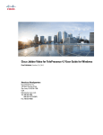
CA700
User & Installation Guide
AVZ-CA-DOC-UIG-04
© 2014 Avizia Inc. All rights reserved. | aviziatech.com
Clinical Assistant | User & Installation Guide
Table of Contents
2
Table of Contents
Table of Contents��������������������������������������������������������������������������������������������������2
Retractable AC Cord Caddy�������������������������������������������������������������������������15
Indications for Use������������������������������������������������������������������������������������������������3
Retractable Network Cord Caddy��������������������������������������������������������������15
Contraindications�������������������������������������������������������������������������������������������3
PC Cabinet with Switch�������������������������������������������������������������������������������16
Safety Precautions������������������������������������������������������������������������������������������������4
Installing Optional Wireless Access Point (WAP)�������������������������������������17
Warning������������������������������������������������������������������������������������������������������������4
Installing Optional Network Switch�����������������������������������������������������������17
Environmental Issues�������������������������������������������������������������������������������������4
Installing Optional WAP and Switch����������������������������������������������������������18
Waste Handling�����������������������������������������������������������������������������������������������4
Enabling Dual Display Option���������������������������������������������������������������������������19
Warnings�����������������������������������������������������������������������������������������������������������������6
Turning the System On��������������������������������������������������������������������������������������20
Operator Safety Summary�����������������������������������������������������������������������������������7
Call Controls��������������������������������������������������������������������������������������������������������21
Equipment Markings��������������������������������������������������������������������������������������������7
Source Control and Rear Interface�������������������������������������������������������������������22
Introduction to CA700������������������������������������������������������������������������������������������8
Headphone and Audio Input����������������������������������������������������������������������������23
System Assembly��������������������������������������������������������������������������������������������������9
Cleaning the System�������������������������������������������������������������������������������������������24
Installing the Cisco PrecisionHD Camera�������������������������������������������������10
Troubleshooting��������������������������������������������������������������������������������������������������25
Installing the Rechargeable Battery����������������������������������������������������������11
Frequently Asked Questions�����������������������������������������������������������������������������26
Installing Cart Options���������������������������������������������������������������������������������������12
Power Schematics����������������������������������������������������������������������������������������������27
Drawer Module, PC Cabinet Module, PC Shelf, and Storage Pods�������12
Audio Schematics�����������������������������������������������������������������������������������������������28
Laptop Shelf��������������������������������������������������������������������������������������������������13
Video Schematics�����������������������������������������������������������������������������������������������29
Scope Hooks��������������������������������������������������������������������������������������������������14
Control Schematics��������������������������������������������������������������������������������������������30
Wireless Access Point Mount����������������������������������������������������������������������14
Technical Specifications������������������������������������������������������������������������������������31
Splash Cover��������������������������������������������������������������������������������������������������14
Electromagnetic Emissions and Immunity Summary����������������������������������32
© 2014 Avizia Inc. All rights reserved. | aviziatech.com | AVZ-CA-DOC-UIG-04
Indications for Use
Clinical Assistant | Installation & User Guide
3
Indications for Use
The Avizia CA700 enables secure and effective audio/video
communication between multiple healthcare providers and
between providers and patients. The system transmits realtime audio and video captured by a high-definition camera
and integrated microphone. It also receives real-time audio
and video from a corresponding functionally like system in
a remote location. Finally, the CA700 supports transmission
of real-time audio and video from peripheral audio/visual
medical devices, which may be connected to standard audio
and video inputs provided on the system.
The CA700 is intended to facilitate remote provider/patient
and provider/provider consultations. These consultations
should always be conducted with a licensed medical professional physically in the room with the patient.
71 in
(180.34 cm)
35 in
(88.9 cm)
280 lbs / 127 kg
33 in
(83.82 cm)
Contraindications
The CA700 is not intended to substitute for the in-person
physical examination of a patient or as a substitute for direct
medical intervention. It is also not intended for real-time,
active, or online patient monitoring, nor is it intended to
provide time sensitive data or alarms. The CA700 does not
support transmission of numerical telemetric/serial data
and is not intended for use with non-audio/visual medical
devices.
Diameter: 27 in. (68.5 cm)
Height: 67 in. (170 cm)
Weight: 170 lb (76.2 kg)
(without accessory options)
© 2014 Avizia Inc. All rights reserved. | aviziatech.com | AVZ-CA-DOC-UIG-04
Safety Precautions
Clinical Assistant | User & Installation Guide
4
Safety Precautions
Warning
Environmental Issues
Precaution should be taken during transportation of the
system. It is recommended that the operator use caution
when wheeling the unit over doorstops and/or into elevators
to ensure their safety and prevent damage to the unit.
Thank you for buying a product which contributes to a reduction in pollution, and thereby helps save the environment.
Our products reduce the need for travel and transport and
thereby reduce pollution. Our products have either none or
few consumable parts (chemicals, toner, gas, paper). Our
products are low energy consuming products.
For Customers In North America
This equipment complies to the limits for a Class A digital
device, pursuant to Part 15 of the FCC Rules.
These limits are designed to provide reasonable protection
against harmful interference when the equipment is operated
in a commercial environment. This equipment generates,
uses, and can radiate radio frequency energy, which may
cause harmful interference to radio communications.
You are cautioned that any changes or modifications not
expressly approved in this manual could void your authority
to operate this equipment
Battery Handling
Batteries for the Remote Control are Long Life Alkaline batteries; please follow guidelines on the packing material for
handling and disposal of the batteries.
The system enclosed battery (rechargeable battery for wireless use) in this product is non-user replaceable and should
be removed by a service technician only.
CAUTION
RISK OF EXPLOSION IF BATTERY IS REPLACED BY AN INCORRECT TYPE. DISPOSE OF USED BATTERIES ACCORDING TO
MANUFACTURER INSTRUCTIONS.
Production of Products
Our factories employ efficient environmental methods for
reducing waste and pollution and ensuring the products are
recyclable.
Waste Handling
EU Battery and WEEE Directives
Your product may contain a user replaceable battery or a
permanently affixed battery as indicated in the user manual.
For product safety and data integrity reasons a permanently
affixed battery should only be removed or replaced professionally by a repair technician or waste management
professional. Please contact Avizia or an authorized service
agent if the product fails to perform due to malfunction of the
permanently affixed battery.
This symbol on a product, battery or packaging
means that the product and/or battery should
not be disposed of with your household waste.
It is your responsibility to dispose of your waste equipment
and batteries separately from your household waste and in
accordance with local laws and regulations. The correct disposal of your old equipment and batteries will help prevent
potential negative consequences for the environment and
human health.
Please use the nearest waste collection facility as directed by
your municipality or your retailer.
© 2014 Avizia Inc. All rights reserved. | aviziatech.com | AVZ-CA-DOC-UIG-04
Important Safeguards
Clinical Assistant | User & Installation Guide
5
Important Safeguards
Using System in a Medical Environment
No currently available technology can completely substitute for the in-person physical examination of an individual
patient. A Cisco Telepresence codec and camera have the
ability to provide high quality audio/high resolution video
over long distances; and when used properly, these products
can provide tools for physicians and other medical professionals who are unable to examine a patient in person.
The use and value of the system will vary depending on the
specific circumstances of the patient’s condition, transmission speed and the ability of audio/visual technology to be
used for remote evaluations. Ultimately, judgments on how
this tool should be used must be at the individual discretion
of the physician or other medical personnel supervising the
patient’s care.
All the equipment connected to this system shall be certified
according to UL Standard UL60601-1 or other IEC/ISO/CSA
Standards applicable to the equipment.
NOTE: The power outlet provided in the system is powered
from an isolation transformer. The maximum output rating of
this outlet is 150 Watts.
CAUTION:
The leakage current could increase when connected to other
equipment.
Wireless Access Point Compliance
Any customer-supplied Wireless Access Point used with
the CA700 must comply with appropriate regulations in the
country of use.
ElectroStatic Discharge (ESD)
The operator should take precautions to avoid touching the
rear panel input and output circuitry and the patient at the
same time.
When subjected to an electrostatic discharge the 12x system
camera image may suffer momentary interruption - this will
self-recover in a few seconds after the discharge.
To isolate the system from the mains supply remove the
mains plug from the wall socket.
To avoid excess electrostatic discharge, floors should be
wood, concrete or ceramic tile. If floors are covered with synthetic material, the relative humidity should be at least 30%
Battery Maintenance
Warning on Power Connection
Use only with the supplied power cords or cords that meet
local hospital-grade requirements. Users in the United States
and Canada should use hospital-grade cords that meet the
following requirements:
United States
Canada
Plug Type
Hospital Grade
Hospital Grade
Cord Type
SJT3 x 18 AWG
SJT3 x 18 AWG
Minimum Cord
Det Rating
10A/125V
10A/125V
Saftey Approval
CSA NRTLus
CSA
To insure maximum longevity of the battery, the CA700
should periodically be operated on battery power until the
“Low Battery ” warning comes on. Once the warning sounds
the system should be reconnected to an AC power source
until the battery is fully charged.
NEVER USE AN EXTENSION CABLE TO POWER THE SYSTEM.
When this system is used together with other equipment in
the patient area, the equipment shall be either powered by
an isolation transformer or connected to the power outlet
that is at the rear of the cart, unless it is certified according to
UL Standard UL60601-1.
© 2014 Avizia Inc. All rights reserved. | aviziatech.com | AVZ-CA-DOC-UIG-04
Warnings
Clinical Assistant | User & Installation Guide
6
Warnings
Not Intended For Dialing Emergency Medical Services
Delay or Choppiness of Audio or Video
Transmission
The CA700 is not intended to make emergency calls. In the
event of an emergency, the user should use a telephone or
device other than the CA700 to call local emergency services.
The CA700 may operate at a delay of up to 150 milliseconds,
depending on network condition. This means that the provider may experience the audio and video transmissions later
then they are really occurring. In cases where the remote
health care provider needs to make time sensitive assessments or give instructions this delay may result in misalignment of audio and visual transmissions to the real-time
procedure and/or inappropriate treatment or diagnosis.
Improper Transport Methods
When transporting the mobile cart over an obstacle greater
than 10 mm, it is recommended that 2 people assist in the
transport. The preferred method is to backing the rear wheels
over the threshold and then rotating such that the front two
wheels are not both elevated off the ground at the same time
while the front of the cart is being tipped over the threshold.
There are handles on the work surface designed for assisting in moving and will serve as the fixed transport position.
There will be a “Do Not Push” label place on a visible area
of the front of the cart. Label information will be in the User
Guide.
Please refer to the Avizia CA700 User and Installation Guide
under “Operator Safety Summary” and “Important Safeguards. See http://www.aviziatech.com.
Loss of Connectivity
During the use of the CA700, a healthcare professional may
lose connectivity with the system. Loss of connectivity can
result from power outages, network outages, failure in the
CA700 software/hardware, or other causes. Loss of connectivity can prevent a health care professional from completing
a patient session in a timely manner. In cases where time is
critical, the user should not use the CA700 and seek an inperson examination from a licensed health care professional.
Proper Training Is Required
Healthcare professionals using the CA700 should be sufficiently trained and familiar with the Installation and User
Guide and the instructions for use. Please refer to the Avizia
CA700 Installation and User Guide (under “Troubleshooting”, “Frequently Asked Questions,” “Safety Precautions” and
“Operator Safety”
See http://www.aviziatech.com.
Camera May Not Focus
There may be times when the system’s main camera or a connected peripheral camera does not focus or loses focus. This
problem can result from equipment malfunction, improper
use of the camera, improper configuration, or other reasons.
An improperly configured or poorly focused camera may reduce the quality of the image. The camera can be maximized
on the inputs on frame rate and resolution. Please refer to
the SX20 codec end user guide “Getting Started Guide” at:
http://www.cisco.com/en/US/products/ps11424/tsd_products_support_series_home.html
Audio Distortions
The CA700 can experience audio distortions due to network
latency, software/hardware malfunction, insufficient bandwidth, or for other reasons. If audio is not of sufficient quality
for the intended use of the CA700, please refer to the Avizia
CA700 Installation and User Guide (under ”Source Controls
and Rear Interface”, “Technical Specifications,” and “Troubleshooting” & “Frequently Asked Questions.” See http://www.
aviziatech.com.
PAL-N Video Signal Not Available
The PAL-N standard video signal is not available on the
CA700.
© 2014 Avizia Inc. All rights reserved. | aviziatech.com | AVZ-CA-DOC-UIG-04
Operator Safety Summary
Clinical Assistant | User & Installation Guide
7
Operator Safety Summary
For your protection, please read these safety instructions
completely before operating the equipment and keep this
manual for future reference. The information in this summary
is intended for persons who operate the equipment as well
as repair (servicing) personnel. Carefully adhere to all warnings, precautions and instructions on the apparatus, or the
ones described in the operating instructions.
Also, adhere to safety guidelines found in manuals for any
peripheral equipment.
Equipment Markings
The “exclamation mark” within an equilateral triangle is
intended to alert the user to the presence of important
operating and maintenance (servicing) instructions within
literature accompanying the equipment.
The potential equalization terminal is connected to the
system chassis. It can be connected to corresponding
terminals on other equipment to eliminate potential
differences. This terminal is not intended for a protective earth
(grounding) connection near this symbol.
Manufacturer
Follow instructions for
use. / Suivez les instructions d’utilisation.
• Water and moisture - Do not operate the equipment under or
near water - for example near a bathtub, kitchen sink, or laundry
tub, in a wet basement, or near a swimming pool or in areas with
high humidity.
• Ventilation - Do not block any of the ventilation openings of the
apparatus. Install in accordance with the installation instructions. Never cover the slots and openings with a cloth or other
material. Never install the apparatus near heat sources such as
radiators, heat registers, stoves, or other apparatus (including
amplifiers) that produce heat.
• Cleaning - Unplug the apparatus from the wall outlet before
cleaning or polishing. Please adhere to the general cleaning
guidelines found in this document’s section: “Cleaning the
System.”
• Attachments - Only use attachments as recommended by the
manufacturer.
• Grounding- This equipment must be grounded. Never defeat the
ground conductor or operate the equipment in the absence of
a suitably installed ground conductor. Contact the appropriate
electrical inspection authority or an electrician if you are uncertain that suitable grounding is available.
• Power-Cord Protection - Route the power cord so as to avoid it
being walked on or pinched by items placed upon or against it,
paying particular attention to the plugs, receptacles, and the
point where the cord exits from the apparatus.
• Mobility – Before moving the system unplug the power cord andnetwork cable and securely wrap them around the cable wrap
brackets. Unplug connected microphone(s) and carry separately.
To move the cart, use one or more of the cart handles. You may
use the camera tilt handle for local repositioning of the camera
only.
DO NOT PUSH OR PULL
THE UNIT BY THE SUPPORT COLUMN ABOVE
THE WORK SURFACE!
Do not push or pull the unit by the support column. Use
the handles found around the work surface.
Cart Handles (4x)
• Accessories - Use only with a cart, stand, tripod, bracket, or table
specified by the manufacturer, or sold with the apparatus. When
a cart is used, use caution when moving the cart/apparatus
combination to avoid injury from tip-over.
• Lightning - Unplug this apparatus during lightning storms or
when unused for long periods of time.
• Servicing - Do not attempt to service the apparatus yourself
as opening or removing covers may expose you to dangerous
voltages or other hazards, and will void the warranty. Refer all
servicing to qualified service personnel.
• Storage - If you need to store the system, ensure that it is stored
in a controlled environment to avoid damage. Refer to the codec
documentation for further guidelines.
• Repacking – Do not throw away the carton and packing materials. They make for an ideal container with which to transport the
system.
• Damaged Equipment - Unplug the apparatus from the outlet
and refer servicing to qualified personnel under the following
conditions:
- When the power cord or plug is damaged or frayed
- If liquid has been spilled or objects have fallen into the apparatus
- If the apparatus has been exposed to rain or moisture
Use two or more people
to move the unit over a
threshold.
- If the apparatus has been subjected to excessive shock by being dropped, or the unit has been damaged
- If the apparatus fails to operate in accordance with the operating instructions.
© 2014 Avizia Inc. All rights reserved. | aviziatech.com | AVZ-CA-DOC-UIG-04
Introduction to Avizia CA700
Clinical Assistant | Installation & User Guide
8
Introduction to Avizia CA700
The Avizia CA700 brings the power of video to healthcare
environments. Designed for mobility and ease of use at the
point of care, the CA700 is a high-definition video collaboration system with functionality that facilitates medical use
cases ranging from remote patient consultations to virtual
care teams and medical education. This mobile telemedicine endpoint offers a total solution approach including
content sharing, recording, firewall traversal, and management capabilities. With the CA700 healthcare providers can
overcome the barrier of distance and work more productively through remote face-to-face collaboration in a medical
setting.
Key Features of the CA700:
• Lightweight and highly mobile with integrated industrial
design to maximize durability and functionality in a
medical environment
• Cisco TelePresence SX Series codec featuring 1080p30
video, full-duplex audio, and high-definition (HD) content sharing
• 1080p HD camera with full pan-tilt-zoom (PTZ) capability
- 4x zoom standard, 12x zoom optional
• 24-inch 1080p HD LED backlit display
• Tactile control panel offering simple system control with
minimal training, plus infrared remote control for full
untethered system operation
• Both AC and rechargeable battery power through
medical-grade isolation transformer
• Flexible range of storage module options for computers,
medical devices, supplies, etc.
• Five 5-inch hospital-grade, antistatic free running castors
with foot locks.
Splash Cover
(OPTION)
PrecisionHD Camera
Camera Shelf
Handle
24” Display
Integrated
Microphone
Scope Hooks
(OPTION)
Wireless Access
Point (OPTION)
Integrated
Speakers
Source
Control
Audio Input
(3.5mm)
Handles (4x)
Power
Outlet (2x)
Ethernet
Power Control
and Battery
Meter Panel
Headphone
Audio Output
(1/4”)
Codec Remote
and Holder
Rear
Interface
Work Surface
Laptop Tray
(OPTION)
Heightadjustable Locking
PC Cabinet
(OPTION)
Fuse (2A)
Potential
Equalization
Terminal
Height-adjustable
Storage Bin
(OPTION)
Height-adjustable
Shelf (OPTION)
Cable
Management
Retractable Network
Cable (OPTION)
Height-adjustable
Locking Drawer
(OPTION)
AC Power Inlet
Retractable Power Cable
(OPTION)
Internal Rechargeable Battery
and Isolation Transformer
5” Locking Wheels
(5x)
© 2014 Avizia Inc. All rights reserved. | aviziatech.com | AVZ-CA-DOC-UIG-04
System Assembly
Clinical Assistant | Installation & User Guide
9
System Assembly
The CA700 comes fully assembled with the exception of the
Cisco PrecisionHD Camera, any optional accessories, and
some cable connections.
Splash Cover
• Cisco PrecisionHD 4xS2 Camera (or 12x option)
• Rechargeable Battery
Scope Hooks
OPTIONS:
• Locking Drawer
- Locking Drawer
• Locking PC/Switch Cabinet
• PC Shelf
• Laptop Tray
- Locking PC/Switch Cabinet
Wireless Access
Point Mount
PC Shelf
• Storage Pod
• Retractable AC Cord Caddy
• Retractable Network Cable Caddy
• Scope Hooks (2)
• Splash Cover
• Wireless Access Point Mount
Retractable Cord Caddy
Laptop Tray
- AC Power option
Tools Required for Assembly
There are no tools required for the base cart configuration.
- Network cable option
Storage Pod
A Phillips Screwdriver will be needed for installing PHD Camera and some optional accessories.
© 2014 Avizia Inc. All rights reserved. | aviziatech.com | AVZ-CA-DOC-UIG-04
Installing the Cisco PrecisionHD Camera
Clinical Assistant | Installation & User Guide
10
Installing the Cisco PrecisionHD Camera
1.
Reach behind the mounted DISPLAY to remove the
THUMBSCREW and COVERPLATE just under the camera
mounting surface.
2.
Secure the PRECISIONHD CAMERA to the CAMERA
SHELF using the THUMBSCREW from the camera
mounting surface.
3.
Replace the COVER PLATE with THUMBSCREW.
4.
Connect the camera cables to the camera. The cable
slack can be stored within the column as desired:
Camera Cables
(to PHD 4xS2 Camera
Adapter Cables or directly to
PHD 12x Camera)
PHD Camera
PHD 4xS2: Requires Camera Adapter Cable, which extends from cables provided in column, to the camera.
PHD 12x: Uses cables provided in the column -- no
adapter required.
Coverplate
CAMERA ADAPTER CABLE
FOR PHD 4xS2
Display
Thumbscrews
PHD 12x
(optional)
PHD 4xS2
CUSTOM
HDMI
CAMERA CABLES
WITHIN COLUMN
CAMERA
ADAPTER
CABLE
CAMERA
CONTROL
HDMI
VIDEO OUT
CAMERA CABLES
WITHIN COLUMN
© 2014 Avizia Inc. All rights reserved. | aviziatech.com | AVZ-CA-DOC-UIG-04
Installing the Rechargeable Battery
Clinical Assistant | Installation & User Guide
11
Installing the Rechargeable Battery
The system’s rechargeable battery is disconnected for shipping and must be connected for proper operation.
NOTE: Ensure AC Power is not connected to the cart when
installing the battery.
1.
Remove the ACCESS PANEL on the lower column by
unscrewing the THUMBSCREW (1) near the top of the
plate.
2.
Remove the WING NUT (1) holding the BASE PLATE in
place.
3.
Remove the BASE PLATE by gently pulling the plate
forward and then up.
4.
Locate the YELLOW BATTERY CONNECTOR that extends
from the battery and plug into the POWER SUPPLY UNIT.
5.
Replace the BASE PLATE and the ACCESS PANEL.
ACCESS PANEL
BATTERY CONNECTOR
BASE PLATE
If the BATTERY has enough charge, then the CA700 is ready
to be configured and begin making calls.
If the BATTERY does not have enough charge, provide power
by plugging the system into an appropriate outlet (120V or
240V) -- this charges the BATTERY while powering the system
with AC power.
50A FUSE
(Field Replaceable -- see
Troubleshooting Section)
It is recommended that the unit is initially charged 4-6 hours
or until the battery meter indicates a full charge.
Make sure the display is ON if it has not turned on automatically.
NOTE: Providing power to the system via the AC power
cord will automatically switch the system from battery
power to AC power; the battery power will shut off and
will begin to charge from the AC power. Ensure the
POWER SWITCH is in the OFF position when connecting
to AC power, and then switch to the ON position to use
AC power and charge the battery.
BATTERY MAINTENANCE: To ensure maximum longevity of the battery, the CA700 should periodically be
operated on battery power until the “Low Battery”
warning comes on. Once the warning sounds the
system should be reconnected to an AC power source
until the battery is fully charged.
© 2014 Avizia Inc. All rights reserved. | aviziatech.com | AVZ-CA-DOC-UIG-04
Installing Cart Options
Clinical Assistant | Installation & User Guide
12
Installing Cart Options
The following describes how the storage options are
installed. While some items are easily installed without the
need for any tools, there are some that will require a screwdriver and minor assembly.
Drawer Module, PC Cabinet
Module, PC Shelf, and Storage
Pods
Determine the desired location(s) of the optional DRAWER,
CABINET, SHELVES, or BINS.
1.
Align and insert the set of hooks, at the back of each
module, to the SUPPORT COLUMN.
2.
Slide in to hook
3.
Press down to secure
Verify locking mechanism on the upper-right hook of
the accessory has “clicked” in place.
TO REMOVE an accessory
1.
PULL and HOLD the LOCK RELEASE TAB on the upperright hook of the accessory
2.
LIFT and PULL the accessory away from the column.
Lock
Release Tab
PULL
MAXIMUM WEIGHT CONSIDERATIONS
Locking Drawer: 15lbs / 6.8kg
PC Cabinet: 25lbs / 11.3kg
Laptop Tray: 8lbs / 3.6kg
PC Shelf: 10lbs / 4.5kg
Storage Pod: 5lbs / 2.3kg
Scope Hook: 3lbs / 1.3kg
Mounting
Hooks
© 2014 Avizia Inc. All rights reserved. | aviziatech.com | AVZ-CA-DOC-UIG-04
Installing Cart Options
Clinical Assistant | Installation & User Guide
13
Installing Cart Options
Laptop Shelf
1.
Remove the WORK SURFACE
• Unscrew the screw at bottom of WORK SURFACE
• Lift and pull the WORK SURFACE from the system to
remove.
• For C20 codec model: If needed, flip the codec up to
gain access to the side holes for mounting the shelf
by removing the small Phillips screw at the bottom of
the codec shelf.
2.
1
Mount the LAPTOP SHELF to the system with the supplied screws (4) as shown.
To operate the LAPTOP SHELF, pull the knob to release the
tray’s locking mechanism and slowly swing the tray to lock
in the closed position (under the work surface) or in the
extended position.
2
CAUTION: During adjustment of laptop tray, the springloaded knob may pinch finger if the knob is grasped beyond
the knob’s head, and pinching may occur while the tray is
adjusted.
This image shows C20 variation of the CA700
© 2014 Avizia Inc. All rights reserved. | aviziatech.com | AVZ-CA-DOC-UIG-04
Installing Cart Options
Clinical Assistant | Installation & User Guide
14
Installing Cart Options
To properly mount the optional SCOPE HOOKS, WIRELESS
ACCESS POINT MOUNT, and SPLASH GUARD, remove the
BACK PANEL of the MONITOR SUPPORT COLUMN by removing the THUMB SCREW located at the top of the support
column. This provides access to mount the options.
Each of these options are installed using the provided WING
NUTS.
Replace the BACK PANEL when finished.
Scope Hooks
Thumb Screw
for Back Panel of
Monitor
Support
Column
Use the provided WING NUTS to mount the scope hooks to
the column as shown.
Wireless Access Point Mount
Splash Cover
and Bracket
Back Panel of Monitor
Support Column
Mount the WIRELESS MOUNTING BRACKET to the column
using the provided WING NUTS.
Secure the Cisco Wireless Access Point, or similar, to the
mounting bracket, as shown, by aligning the mounting pegs
to the bracket.
Splash Cover
Scope Hooks
Wireless
Mounting Bracket
Mount the splash cover’s BRACKET to the MONITOR SUPPORT COLUMN with the provided WING NUTS.
Secure the SPLASH COVER to the BRACKET.
Hang the transparent, plastic guard, as needed, onto the
posts atop the SPLASH COVER.
© 2014 Avizia Inc. All rights reserved. | aviziatech.com | AVZ-CA-DOC-UIG-04
Installing Cart Options
Clinical Assistant | Installation & User Guide
15
Installing Cart Options
Retractable AC Cord Caddy
This option is available for North America ONLY.
1.
Insert the MOUNTING BRACKETS to the side of the SUPPORT COLUMN as shown.
2.
Position the RETRACTOR HOUSING to fit the flanges
over the screws of the MOUNTING BRACKETS.
3.
Secure the RETRACTOR HOUSING with the FASTENING
KNOBS.
4.
Remove the existing power cord by unscrewing the
CORD STRAIN RELIEF and replace with the power cord
from the rear of the RETRACTOR HOUSING.
5.
Secure the CORD STRAIN RELIEF over the power cord
with an appropriate amount of slack.
6.
Pull and plug the retractable cable into an appropriate
outlet to provide AC power to the system.
To retract the power cord, unplug from outlet, gently
tug on cable to retract into the housing.
Retractable Network Cord
Caddy
3
FASTENING
KNOBS (2x)
SUPPORT
COLUMN
RETRACTOR
HOUSING
2
MOUNTING
BRACKETS
1
5
TO OUTLET
CORD STRAIN
RELIEF
6
TO IEC INLET
4
This option installs similarly as the AC Cord Caddy option.
Once it is mounted to the cart:
1.
Connect the loose end of the cable to the NETWORK
port on the rear of the cart. If using an optional switch,
connect to the switch instead.
2.
Connect the retractable end of the cable to an appropriate network source.
© 2014 Avizia Inc. All rights reserved. | aviziatech.com | AVZ-CA-DOC-UIG-04
Installing Cart Options
Clinical Assistant | Installation & User Guide
16
Installing Cart Options
PC Cabinet with Switch
1
The locking PC CABINET option provides a shelf to mount
and house an optional network switch to provide greater
network flexibility.
1.
Attach the angle brackets to the sides of the Switch with
the provided Thumb Screws.
2.
Align and mount the SWITCH to the SHELF with the
provided WING NUTS.
3.
Insert the SHELF with the mounted SWITCH into the PC
CABINET.
4.
Secure the SHELF to the PC CABINET with the provided
WING NUTS.
2
Use the rear ACCESS PANELS for cable management.
CAUTION: Remove the locking KEY when moving the
CA700. Failure to remove the key may result in damaging
the key, damaging other equipment, or personal injury.
3
4
© 2014 Avizia Inc. All rights reserved. | aviziatech.com | AVZ-CA-DOC-UIG-04
Installing Cart Options
Clinical Assistant | User & Installation Guide
17
Installing Cart Options
Installing Optional Wireless Access Point (WAP)
Installing Optional Network Switch
If wireless network connectivity is required, mount a wireless
access point (WAP) securely to the cart (see Wireless Access
Point Mount).
If additional network ports are required, mount a network
switch into the PC Cabinet (see PC Cabinet with Switch).
NOTE: Power to the cart should be removed before
installing the WAP or switch.
NOTE: Power to the cart should be removed before
installing the WAP or switch.
1.
2.
3.
If required, install the Power Injector into the base of the
cart, up against the system’s Isolation Transformer, and
plug into the provided Power Bar.
Use the integrated Network Cable, available inside the
column, to connect the WAP and the “AP” (Access Point)
port on the Power Injector.
Mount the Power Supply for the Switch into the base of
the cart, up against the system’s Isolation Transformer,
and plug into the provided Power Bar.
2.
Run the Switch’s Power Cable up through the column
and plug into the Switch housed inside the PC Cabinet.
3.
Route a supplied Network Cable from the NETWORK port
on the rear of the cart to the rear of the PC Cabinet and
plug into the Switch.
Connect a supplied Network Cable from the “Switch”
port on the Power Injector to the
NETWORK port on the rear
of the CA700.
NOTE: Clip the Network
Cable to the Strain Relief
Clip at the bottom right
corner of the interface place
with the NETWORK port.
4.
WAP
1.
Make the appropriate
network configurations per
the requirements of your
organization.
NOTE: Clip the Network
Cable to the Strain Relief
Clip at the bottom right
corner of the interface plate
with the NETWORK port.
Integrated
Network Cable
Strain
Relief Clip
4.
NOTE: If using the optional
Retractable Network Caddy,
connect the loose end of the
cable to the Switch, and connect
the retractable end of the
cable to an appropriate
network source.
to POWER BAR
inside BASE
ACCESS
POINT
5.
SWITCH
POWER
INJECTOR
Connect a Network Cable
from the Switch to an
appropriate network source.
Make the appropriate
network configurations per
the requirements of your
organization.
Strain
Relief Clip
NETWORK
SWITCH
Optional Retractable
Network Caddy
to POWER BAR
inside BASE
POWER for
SWITCH
© 2014 Avizia Inc. All rights reserved. | aviziatech.com | AVZ-CA-DOC-UIG-04
Installing Cart Options
Clinical Assistant | User & Installation Guide
18
Installing Cart Options
Installing Optional WAP and Switch
NOTE: Power to the cart should be removed before installing
the WAP or switch.
1.
Mount the Power Supply for the Switch into the base
of the system and plug into the provided Power Bar.
2.
Run the Switch’s Power Cable up through the column
and plug into the Switch housed inside the PC Cabinet.
3.
Reroute the integrated Network Cable, available inside
the column, up into the rear of the PC Cabinet and plug
into the Switch. Connect the other end to the WAP.
4.
Connect a supplied Network Cable from the Switch to
the NETWORK port on the rear of the cart.
NOTE: Clip the Network Cable
to the Strain Relief Clip at
the bottom right corner of
the interface plate with the
NETWORK port.
5.
WAP
Make the appropriate
network configurations per
the requirements of your
organization.
Integrated
Network Cable
NETWORK
SWITCH
Strain
Relief Clip
to POWER BAR
inside BASE
POWER for
SWITCH
© 2014 Avizia Inc. All rights reserved. | aviziatech.com | AVZ-CA-DOC-UIG-04
Installing Cart Options
Clinical Assistant | Installation & User Guide
19
Installing Cart Options
Enabling Dual Display Option
The CA700 can accommodate a second display for an
enhanced telepresence session or presentation. An HDMI EXTENSION CABLE is made available for easy access to connect
to within the support column.
1.
Remove the ACCESS PANEL on the lower column by
unscrewing the THUMBSCREW (1) near the top of the
plate.
2.
Locate the HDMI EXTENSION and securely connect the
USER SUPPLIED HDMI CABLE to the EXTENSION.
3.
Replace the ACCESS PANEL while ensuring the HDMI
CABLE is able to exit the COLUMN through the egress at
the top of the ACCESS PANEL.
4.
Connect the HDMI Cable to the display you intend to
use.
5
4
NOTE: Ensure power is provided to the display and is ON.
3
NOTE: Place the second display on a secure and stable location to avoid damage or injury.
5.
Press and hold
(LAYOUT Button) on the SOURCE
CONTROL interface for five seconds to enable the Dual
Display option.
NOTE: When a second display is connected, the default mode
will present Single Display mode where the displays are mirrored.
6.
2
1
Use the SOURCE CONTROLS to present different content on the second display.
NOTE: Turning the system off with the Power Button on the
Battery Meter Panel will revert the Dual Display setting to
Single Display mode. Placing the system on Standby does not
alter the Dual Display setting.
© 2014 Avizia Inc. All rights reserved. | aviziatech.com | AVZ-CA-DOC-UIG-04
Turning the System On
Clinical Assistant | User & Installation Guide
20
Turning the System On
When connected to AC outlet, simply turn ON the unit with
the power switch at the rear of the unit’s BASE and then
press and hold the system’s POWER BUTTON on the POWER
CONTROL AND BATTERY METER PANEL for one second.
AC Power Switch
AC Power Input
POWER BUTTON
This button turns the Power Supply
Module’s outlets (and any connected equipment) on and off.
To turn the Power Supply Module’s outlets ON: Press and hold
the “Power” button for one second.
The alarm will beep once briefly
after one second has passed. Release the button. The “Power” LED
will illuminate. The “Power” button
will turn the outlets on regardless of
whether the Power Supply Module
is plugged in or not.
POWER LED
This green LED
indicates whether
the Power Supply
Module’s outlets
are ON or OFF.
To turn the Power Supply
Module’s outlets OFF: Press and
hold the “Power” button for one
second. The alarm will beep once
briefly after one second has passed.
Release the button. The “Power”
LED will turn off.
BATTERY CHARGE LED METER
These LEDs will illuminate in several sequences
to indicate the approximate charge level of the
Battery Module. See “Operation” section for charts
illustrating Battery Charge LED Meter Display depending on different charge levels while discharging and charging.
POWER CONTROL AND BATTERY METER PANEL
ALARM MUTE BUTTON
This button silences the Power
Supply Module’s low battery
alarm. To silence the low battery
alarm, briefly press and release
the Alarm Mute button. The low
battery alarm will beep once per
second unless it is silenced. Once
the charge level falls below 30%
(and shutdown is imminent) the
alarm will resume again after one
minute. Once the charge level
falls below 30%, the user should
save open files and safely shut
down connected equipment
immediately. If the cart is unattended and PowerAlert Software
is loaded on a computer connected to the Power Supply Module, PowerAlert will automatically
save open files prior to automatic
shutdown.
MOBILE OPERATION (UNPLUGGED / DISCHARGING)
When operating with the battery only, press and hold the
system’s POWER BUTTON for one second on the POWER
CONTROL AND BATTERY METER PANEL.
NOTE: The switch at the unit’s base toggles AC power only.
The battery will operate when it has a charge and the system
is not connected to AC power. The battery will not charge
unless the AC switch is on and plugged in to an AC outlet.
Unplug the Power Supply Module from the AC wall outlet.
Ensure that the cord is safely stowed aboard the cart to reduce
the risk of damage.
Use connected equipment between charges, depending on
battery conditions, environmental conditions and equipment
load. As the Battery Module’s charge is depleted, the Battery
Charge LED Meter will indicate the approximate charge level
(see chart).
To turn the Power Supply Module’s outlets (and any connected
equipment) OFF and stop the battery from discharging, press
the “Power” button for one second. The alarm will beep once
briefly after one second has passed. Release the button. All
LEDs will be OFF.
STATIONARY OPERATION (PLUGGED IN / CHARGING)
Plug the Power Supply Module into a live AC wall outlet.* The
Power Supply Module will deliver AC power to connected
equipment while simultaneously charging the Battery Module.
Use connected equipment indefinitely as long as the Power
Supply is connected to a live AC outlet. If the utility power fails,
due to a blackout or severe brownout, the Power Supply will
automatically support connected equipment with AC power
from the Battery Module (if adequately charged). When power
resumes after a blackout, the Power Supply will automatically resume supplying AC power and recharging the Battery
Module.
© 2014 Avizia Inc. All rights reserved. | aviziatech.com | AVZ-CA-DOC-UIG-04
Clinical Assistant | User & Installation Guide
Call Controls
21
Call Controls
The CA700 makes video calls and presentations using the
Cisco Telepresence Codec SX20, housed within the system,
and its accompanying Control Interface. A Remote Control is
included to provide advanced codec functionality.
The system control interface on the CA700 provides simple
source control options once you are connected to a video
call.
Please refer to the “video systems gettting started guide” for
instructions on making calls and using the remote control.
You may access SX20 codec information online at:
http://www.cisco.com/en/US/products/ps11424/
© 2014 Avizia Inc. All rights reserved. | aviziatech.com | AVZ-CA-DOC-UIG-04
Source Control and Rear Interface
Clinical Assistant | User & Installation Guide
22
Source Control and Rear Interface
The REAR INTERFACE provides video, audio, and computer connectivity. The corresponding SOURCE CONTROLS found at the front of the CA700 are designed to
provide simple use and quick access to sources when in a call or for local presentation.
VOLUME - Increase or decrease the volume output from the system’s
speakers or connected headphones.
CAMERA CONTROL - Control the system’s camera position.
ZOOM - Increase or decrease the system’s camera zoom.
LAYOUT - Toggle through various screen layouts from the Cisco Codec
Refer to the codec’s documentation to understand the various layouts
when in a call and when not in call.
- SOURCE CONTROLS -
CAMERA - Present the system camera.
COMPUTER - Present the connected computer.
1-5
VIDEO SOURCES - Display the video sources connected to the
corresponding video inputs on the REAR INTERFACE.
1
HDMI IN or S-VIDEO IN (S-VIDEO ONLY if no HDMI signal present)
2
HDMI IN or S-VIDEO IN (S-VIDEO ONLY if no HDMI signal present)
3
DVI-I IN or S-VIDEO IN (S-VIDEO ONLY if no DVI signal present)
- REAR INTERFACE -
DVI-I IN and 3.5mm STEREO MINI PLUG
3.5mm QUICKSET MIC IN (for additional coverage)
USB 1-3 Used for diagnostics, firmware updates, and configuration.
4
COMPOSITE VIDEO IN
5
COMPOSITE VIDEO IN
6
COMPOSITE VIDEO IN (corresponds to
[ DIGITAL INTERFACE ]
[ ANALOG INTERFACE ]
if no DVI signal present)
ANALOG VIDEO OUT (outputs signal from S-VIDEO IN 1, 2, 3 and
COMPOSITE VIDEO IN 4, 5, 6)
© 2014 Avizia Inc. All rights reserved. | aviziatech.com | AVZ-CA-DOC-UIG-04
Headphone and Audio Input
Clinical Assistant | Installation & User Guide
23
Headphone and Audio Input
Headphone Output
The 1/4” HEADPHONE OUTPUT at the left of the SOURCE
CONTROLS panel provides audio through a connected
headphone. When connected, the audio will be cut off from
the integrated speakers -- audio is only heard through the
headphones.
Control the headphone volume using the VOLUME CONTROLS on the Source Controls panel.
Audio Input
The 3.5mm line level AUDIO INPUT is located at the right of
the SOURCE CONTROLS panel. The audio from the connected source (stethoscope or other) will be transmitted
and heard locally through the system’s speakers. If using
a stethoscope, it is recommended that the HEADPHONE
AUDIO OUT be used to listen to the stethoscope’s audio.
1/4” Headphone
Audio Output
Volume Controls
3.5mm Audio Input
Integrated Speakers (2x)
© 2014 Avizia Inc. All rights reserved. | aviziatech.com | AVZ-CA-DOC-UIG-04
Cleaning the System
Clinical Assistant | User & Installation Guide
24
Cleaning the System
The surface materials of the CA700 are durable and easy to
maintain.
Wilsonart® Atlantis D525-60
Please refer to the respective Materials Safety Data Sheets
(MSDS) for detailed descriptions for each product from its
manufacturer.
Clean with warm water and mild soaps,
such as those used for hands or dishes.
Avoid cleansers containing abrasives,
acids, or alkalis.
DuPontTM Corian® Solid Surface
www.dupont.com
www.corian.com
(blue inlaid laminate material)
Stubborn stains may be removed with
a 1.5 minute exposure to hypochlorite
bleach (such as Clorox®)followed by a
clean water rinse.
DuPontTM Corian® Solid Surface
(light-colored solid material)
Wilsonart® Chemsurf®
www.wilsonartlaminate.com
800-433-3222
It is recommend that you not allow any
of the following reagents to remain in
contact with the decorative surface:
General and everyday cleaning can be done
by wiping the surface with a damp cloth or
sponge, then dry with soft cloth or paper
towels. An ammonia-based, non-abrasive
cleaner may be used for stains.
1. Hypochlorite bleach, except as
described above
2. Hydrogen peroxide solution
3. Mineral acids, hydrochloric acid
such as Lime-A-Way™, sulfuric or
nitric acid
4. Caustic solutions containing greater
than 2% lye, such as Drano®
5. Sodium bisulfate, such as SaniFlush®
6. Potassium permanganate
7. Berry juices
8. Silver nitrate, in 1% concentration
9. Gentian violet
10. Mild silver protein, such as 20%
Argyrol
11. Bluing
12. Fabric dye, such as Tintex® or Rit®
13. Alcohol containing 1% iodine in
solution.
Disinfect the surface with the appropriate
sterilant or disinfectant.
Prolonged exposure to concentrated,
undiluted disinfectant solutions may degloss
or etch solid surface material and require
refinishing to restore the surface to its original condition. Using a wet Scotch-Brite® pad
and bleaching and/or abrasive cleanser may
restore the surface finish.
GENERAL CLEANING:
1. Before cleaning, ensure that the monitor is
turned off.
2. Direct the suction nozzle of vacuum
cleaner to remove dirt/dust accumulated in
crevices. Hand brush may be used to assist
in removing settled dirt/dust.
3. Use cloth dampens with ethyl alcohol
to wipe clean the surfaces. Do not use
excessive alcohol as the disinfectant is
flammable.
5. The glass surface of video display terminals
with cathode ray tubes may be cleaned
and disinfected using diluted hypochlorite
solution.
4. Use 0.1% hypochlorite solution to wipe
clean the surface of CPU or laptop and
monitor casings. Wait for 5 minutes and use
another piece of cloth dampened with water
to clean off residual hypochlorite.
6. The video display surface of LCD monitor
should be wiped gently using a damp cloth.
© 2014 Avizia Inc. All rights reserved. | aviziatech.com | AVZ-CA-DOC-UIG-04
Troubleshooting
Clinical Assistant | User & Installation Guide
25
Troubleshooting
POWER
No power to camera
No power to cart
Verify power to the cart and verify the connection
to the camera control port of the camera.
Verify the unit is plugged in and the rear input
switch is on. Verify the power has been turned
on both at the AC power control at the base of
the cart and the battery meter panel beneath the
display.
VIDEO
No video on the monitor(s)
No battery power to cart
Verify the battery is connected properly and the
power button has been pressed for one second
on the battery meter panel beneath the display.
Test and replace the 50A fuse if necessary. The
50 amp inline fuse, used to protect the battery
and Isolation transformer. To remove the fuse,
ensure the system is powered off, disconnect
the power from AC source, remove the lid of the
base section to access the power compartment,
disconnect the yellow battery terminal from
the isolation transformer, open the plastic fuse
compartment, extract fuse and replace with
new Cooper Bussmann-MAX50 (red color) or
equivalent (32 Vdc, 50A, 1000A IR). Reconnect
battery terminal, secure the lid of the power
compartment. CAUTION: Installation of incorrect
fuse could result in a fire.
No power to monitor
Verify power to the cart and the monitor are
switched ON. Once on, powering on/off the cart
will automatically power the monitors.
Make sure power is going to the monitor(s) and
the DVI-D input source is selected on the monitor. Ensure the codec is not in a sleep state by
pressing a button on the remote control or front
button panel.
Can’t see the far end in a call, selfview
only
Verify that the selfview is not selected with the
remote control. Pressing the selfview button on
the remote control will toggle between far and
near end video.
Far side video blocky/discolored/frozen
If disruptions are apparent in the datastream,
view the percentages of lost packets in the call
status pages. Attempting calls at lower bandwidths may lessen or eliminate the disruptions.
How do I see my selfview
PC not recognized by the codec, not
shown on the monitor when selecting
PC input
Maximum resolution for the DVI and HDMI inputs
is 1920 x 1080 @ 60 Hz (1920 x 1200 at 50 Hz).
Resolutions above that will not be recognized by
the codec.
Presenter Option issues/No Content
sharing
The Natural Presenter Package (NPP) option may
not be installed. Check the system information
screen to verify the NPP is installed. The NPP
should be default on the system. If the package is
not installed, contact technical services).
Pressing the selfview button on the remote control will toggle between far and near end video.
CONTROL
No control of the camera
Verify power to the camera and no menus are on
the screen for remote operation. Remote should
be pointed at the camera. Verify remote control
operation by pointing the remote directly into
the lens of the camera at a distance of 2-3 inches.
When viewing the selfview the IR transmitter
should be blinking. If not, change remote control
batteries.
Not able to switch video inputs/buttons
Verify Dataport 1 baud rate is set to 38400 N,8,1 in
the dataport advanced settings.
Remote control not working
AUDIO
No audio from the system
Use volume controls to make sure the volume is
at a reasonable level (approximately 75%). Make
sure the headphone jack is clear. Audio alert
tones and ringer settings may be sampled to
verify audio from the codec.
Far side cannot hear me
Remote should be pointed directly at the camera
for operation. Correct remote control operation
can be verified by pointing the remote directly
into the lens of the camera. The IR transmitter
should be blinking. If there no indication of transmission, change remote control batteries.
For additional Cisco SX20 codec troubleshooting articles please visit:
http://www.cisco.com/cisco/web/support/
Verify that the microphone is not muted (no onscreen mute icon). Check the audio input levels
screen in the codec’s advanced configuration for
microphone 1 .
© 2014 Avizia Inc. All rights reserved. | aviziatech.com | AVZ-CA-DOC-UIG-04
Frequently Asked Questions
Clinical Assistant | User & Installation Guide
26
Frequently Asked Questions
How do I obtain the software version and IP address?
Who do I contact for system repairs or technical assistance?
With remote press home button to display the home menu and then press the fifth soft key
(top of remote) which will display the system information.
For assistance regarding repairs to the CA700, contact Avizia:
http://www.aviziatech.com
Where can I find additional information, downloads, and manuals?
Additional information can be found at the Avizia website listed below.
http://www.aviziatech.com/support.html
How many devices may I connect to the AC outlets on the rear of the cart?
Americas Headquarters:
Avizia
12018 Sunrise Valley Drive, Suite 150
Reston, VA 20194
www.aviziatech.com
The system will allow a maximum of 150 Watts from the rear AC outlets.
Can I access the system remotely?
Technical Support:
www.aviziatech.com/support.html
Call control and endpoint configuration is available through the codec’s web interface. Enter
the username and password for permissions. The default username is “admin” without a
password.
© 2014 Avizia Inc. All rights reserved. | aviziatech.com | AVZ-CA-DOC-UIG-04
Clinical Assistant | User & Installation Guide
Power Schematics
27
Power Schematics
NOTE: The battery in this product is non-user replaceable
and should be removed by a service technician only.
© 2014 Avizia Inc. All rights reserved. | aviziatech.com | AVZ-CA-DOC-UIG-04
Clinical Assistant | User & Installation Guide
Audio Schematics
28
Audio Schematics
© 2014 Avizia Inc. All rights reserved. | aviziatech.com | AVZ-CA-DOC-UIG-04
Clinical Assistant | User & Installation Guide
Video Schematics
29
Video Schematics
© 2014 Avizia Inc. All rights reserved. | aviziatech.com | AVZ-CA-DOC-UIG-04
Clinical Assistant | User & Installation Guide
Control Schematics
30
Control Schematics
© 2014 Avizia Inc. All rights reserved. | aviziatech.com | AVZ-CA-DOC-UIG-04
Technical Specifications
Clinical Assistant | User & Installation Guide
31
Technical Specifications
UNIT DELIVERED COMPLETE WITH:
Base Cart with Cisco SX20 codec, PrecisionHD
4xS2 camera, 24” widescreen LCD, Integrated
microphone and speakers, rechargeable battery,
remote control, and cables.
DISPLAY
24-in. widescreen LCD/LED backlight monitor
Maximum resolution: 1920x1080
Color support: 16.7 million colors
Response time: 5 ms
Display positions adjustment: Tilt
Display screen coating: Antiglare
Features: f-Engine technology, SUPER energy
saving technology
Image contrast ratio: 1000:1 and 5000000:1
(dynamic)
Image brightness: 250 cd/m2
Image maximum H-View angle: 170
Image maximum V-View angle: 160
Kensington Lock Connection
VIDEO INPUTS
Three (3) S-video inputs (4-pin mini din connectors)
Three (3) composite inputs (RCA connectors)
PAL/NTSC
Three (3) High-Definition Multimedia Interface
(HDMI) inputs (one designated as main camera
input); supported formats:
1920x1080@60Hz(1080p60)
1920x1080@50Hz(1080p50)
1920x1080@30Hz(1080p30)
1280x720@60Hz(720p60)
1280x720@50Hz(720p50)
1440x900@60Hz(WXGA+)
1280x768@60Hz(WXGA)
1280x1024@60,75Hz(SXGA)
1024x768@60,75Hz(XGA)
800x600@60,72,75,85Hz(SVGA)
640x480@60Hz(VGA)
Two (2) Digital Visual Interface Input (DVI-I)
inputs (one designated as PC input); supported formats:
Analog (Video Graphics Array [VGA]):
1920x1080@60Hz(1080p60)
1280x720@60Hz(720p60)
1440x900@60Hz(WXGA+)
1280x768@60Hz(WXGA)
1280x1024@60,75Hz(SXGA)
1024x768@60,75Hz(XGA)
800x600@60,72,75,85Hz(SVGA)
640x480@60Hz(VGA)
Digital (DVI-D)
1920x1080@60Hz(1080p60)
1920x1080@50Hz(1080p50)
1920x1080@30Hz(1080p30)
1280x720@60Hz(720p60)
1280x720@50Hz(720p50)
1440x900@60Hz(WXGA+)
1280x768@60Hz(WXGA)
1280x1024@60,75Hz(SXGA)
1024x768@60,75Hz(XGA)
800x600@60,72,75,85Hz(SVGA)
640x480@60Hz(VGA)
VIDEO OUTPUTS
One (1) composite output (RCA connector)
One (1) HDMI output (main display); supported
formats:
1920x1080@60Hz(1080p60)
1280x720@60Hz(720p60)
1280x768@60Hz(WXGA)
1280x1024@60Hz(SXGA)
1024x768@60Hz(XGA)
800x600@60Hz(SVGA)
640x480@60Hz(VGA)
AUDIO INPUTS
Two microphones, 4 pin MiniJack with mono
signal with 1 echo canceller
Two 3.5-mm audio inputs, line level: 1 back
of system for PC audio, 1 front of system for
electronic audio systems
AUDIO OUTPUT
One 1/4 Phono line level: front of system for
Head Phones
CAMERA
Cisco TelePresence PrecisionHD Camera:
1080p
One-third-inch complementary metal oxide
semiconductor (CMOS)
4x zoom or 12x zoom
+15° and -25° tilt, +/- 90° pan
43.5° vertical field of view
72° horizontal field of view
Focus distance 0.3m-infinity
1920x1080 pixels progressive@30 frames per
second (fps) (4x version)
1920x1080 pixels progressive@60 fps (12x
version)
Other formats supported (configurable
through dip-switch, 12x version only):
1920x1080@60fps (HDMI only)
1920x1080@50fps (HDMI only)
1920x1080@30fps
1920x1080@25fps
1280x720@60fps
1280x720@50fps
1280x720@30fps
1280x720@25fps
Automatic or manual focus, brightness, and
white balance
Far-end camera control
Kensington Lock Connection
USER INTERFACE
TRC 5 I/R remote control for full system control
“One-touch” tactile control panel for supple-
mental control of volume, camera, and video
source
OTHER INTERFACES
Three USB inputs for diagnostics and upgrades
BANDWIDTH
H.323 and Session Initiation Protocol (SIP) up
to 6 Mbps point-to-point
720p30 from 768 kbps
720p60 from 1152 kbps
1080p30 from 1472 kbps
IP NETWORK FEATURES
Domain Name System (DNS) lookup for service
configuration
Differentiated Services (quality of service
[QoS])
IP adaptive bandwidth management (including flow control)
Auto gatekeeper discovery
Dynamic playout and lip-sync buffering
H.245 dual-tone multifrequency (DTMF) tones
in H.323
Date and time support with Network Time
Protocol (NTP)
Packet loss-based downspeeding
Uniform Resource Identifier (URI) dialing
TCP/IP
Dynamic Host Configuration Protocol (DHCP)
IEEE 802.1x network authentication
ClearPath
VIDEO STANDARDS
H.261, H.263, H.263+, H.264
VIDEO FEATURES
Native 16:9 widescreen
Advanced screen layouts
Intelligent video management
Local auto layout
LIVE VIDEO RESOLUTIONS (ENCODE and
DECODE)
176x144@30 fps (QCIF)
352x288@30 fps (CIF)
512x288@30 fps (w288p)
576x448@30 fps (448p)
768x448@30 fps (w448p)
704x576@30 fps (4CIF)
1024x576@30 fps (w576p)
1280x720@30 fps (720p30)
1920x1080@30 fps (1080p30) (requires option)
512x288@60 fps (w288p60)
768x448@60 fps (w448p60)
1024x576@60 fps (w576p60)
1280x720@60 fps (720p60) (requires option)
640x480@30 fps (VGA)
800x600@30 fps (SVGA)
1024x768@30 fps (XGA)
1280x768@30 fps (WXGA)
AUDIO STANDARDS
G.711, G.722, G.722.1, 64 kbps MPEG4 AAC-LD
AUDIO FEATURES
CD-quality 20-kHz mono
One acoustic echo canceller
Automatic Gain Control (AGC)
Automatic noise reduction
Active lip synchronization
DUAL STREAM
H.239 (H.323) dual stream
Binary Floor Control Protocol (BFCP) (SIP)
dual stream
Support for resolutions up to WXGAp15 (main
video maximum 720p30)
PROTOCOLS
H.323, SIP
NETWORK INTERFACES
One LAN or Ethernet (RJ-45) 10/100/1000 Mbps
FIREWALL TRAVERSAL
Cisco TelePresence Video Communication
Server Expressway
H.460.18 and H.460.19 Firewall Traversal
EMBEDDED ENCRYPTION
H.323 and SIP point-to-point
Standards-based: H.235v3 and Advanced
Encryption Standard (AES)
Automatic key generation and exchange
Support in dual stream
Auto NAT
SIP ICE
SECURITY FEATURES
Management through Secure HTTP (HTTPS)
and Secure Shell (SSH) Protocol
IP administration password
Menu administration password
Disable IP services
Network settings protection
SYSTEM MANAGEMENT
Support for Cisco TelePresence Management
Suite
Total management through embedded Simple
Network Management Protocol (SNMP), Telnet,
SSH, XML, and
Simple Object Access Protocol (SOAP)
Remote software upload: Through web server,
Secure Copy Protocol, HTTP, and HTTPS
Remote control and on-screen menu system
One RS-232 for local control and diagnostics
(Y-cable required)
Unlimited entries using server directory
Lightweight Directory Access Protocol (LDAP)
and H.350
Unlimited number for corporate directory (available with Cisco TelePresence Management Suite
local directory: 200 numbers)
Received calls
Placed calls
Missed calls with date and time
PHYSICAL DIMENSIONS
Diameter: 27 in. (68.5 cm)
Height: 67 in. (170 cm)
Weight: 170 lb (77.11 kg) (without accessory
options)
POWER
120 VAC, 60 Hz, 5.1 A or 230 VAC, 50 Hz, 2.7 A
90 watts (nominal) up to 240 watts maximum
with peripheral equipment
40 Ah rechargeable battery
Rear of cart: Two 120 VAC, 60 Hz or 230 VAC,
50 Hz -- 150 watts maximum medical grade AC
receptacles for peripheral equipment
Medical grade isolation transformer
OPERATING TEMPERATURE AND HUMIDITY
50 to 95°F (10 to 35°C) ambient temperature
20 to 90% relative humidity (RH)
Atmospheric pressure: 700 to 1060 hPa
STORAGE AND TRANSPORT TEMPERATURE
14 to 140°F (-10 to 40°C) at RH 10 to 80% (noncondensing) at RH 20 to 90%
Atmospheric pressure: 700 to 1060 hPa
APPROVALS AND COMPLIANCE
IEC 60601-1-2nd edition
IEC 60601-1-3rd edition
IEC 60601-1-2
IEC 60950-1
EN 60950-1
EN 60601-1-2
UL 60601-1
UL 60950-1
CSA C22.2 No. 60601.1
CSA C22.2 No. 60950-1
Compliance with FCC 47 CFR Part 15
FDA Class I Medical Device Data System
(MDDS)
Medical Device Directive EN 60601-1 Class I
Equipment
Patient Applied Parts - Type B equipment.
Continuous Operation (Mode of Operation)
DIRECTORY SERVICES
Support for local directories (My Contacts)
Corporate directory
© 2014 Avizia Inc. All rights reserved. | aviziatech.com | AVZ-CA-DOC-UIG-04
Electromagnetic Emissions and Immunity Summary
Clinical Assistant | User & Installation Guide
32
Electromagnetic Emissions and Immunity Summary
The Teleconferencing Unit is intended for use in the electromagnetic environment specified below. The customer or the user of the Teleconferencing Unit should assure that it is used in such an environment.
Guidance and manufacturer’s declaration -- electromagnetic emissions -- for all ME
equipment and ME systems (See clause 5.2.2.1 c) of IEC 60601-1-2:2007)
Compliance
Electromagnetic environment - guidance
RF emissions
CISPR 11
Group 1
The Clinical Assistant generates RF energy
only as a by-product of its internal functions.
Therefore, its RF emission are very low and
are not likely to cause any interference in
nearby electronic equipment.
RF emissions
CISPR 11
Class A
Emissions test
Immunity
test
IEC 60601 test
level
Compliance
level
Electrostatic
discharge
(ESD)
±6 kV contact
±6 kV contact
±8 kV air
±8 kV air
±2 kV for power
supply lines
±2 kV for power
supply lines
EIC 61000-4-4
±1 kV for input/
output lines
±1 kV for input/
output lines
Surge
±1 kV differential
mode
±1 kV differential
mode
±2 kV common
mode
±2 kV common
mode
<5 % UT
(>95 % dip in
UT) for 0,5 cycle
<5 % UT
(>95 % dip in UT)
for 0,5 cycle
40 % UT
(60 % dip in UT)
for 5 cycles
40 % UT
(60 % dip in UT)
for 5 cycles
70 % UT
(30 % dip in UT)
for 25 cycles
70 % UT
(30 % dip in UT)
for 25 cycles
<5 % UT
(>95 % dip in
UT) for 5 sec
<5 % UT
(>95 % dip in UT)
for 5 sec
IEC 61000-4-2
The Clinical Presence is suitable for use in
all establishments other than domestic and
those directly connected to the public lowvoltage power supply network that supplies
buildings used for domestic purposes.
Harmonic
emissions IEC
61000-3-2
Class A
Voltage fluctuation/flicker
emissions IEC
61000-3-3
Complies
Electrical fast
transient/
burst
IEC 61000-4-5
Recommended separation distances between portable and mobile RF communications
equipment and the ME equipment or ME system (See clause 5.2.2.2) of IEC 60601-1-2:2007)
The Clinical Assistant is intended for the use in an electromagnetic environment in which
radiated RF disturbances are controlled. The customer or the user if the Teleconferencing Unit can help prevent electromagnetic interference by maintaining a minimum
distance between portable and mobile RF communications equipment (transmitters)
and the Teleconferencing Unit as recommended below, according to the maximum
output power of the communications equipment
Rated maximum
output power on
transmitter W
Guidance and manufacturer’s declaration -- electromagnetic immunity -- For all ME
equipment and ME systems (See clause 5.2.2.1 f) of IEC 60601-1-2:2007)
Separation distance according to frequency
of transmitter m
150 KHz to 80 MHz
80 MHz to 800 MHz
800 MHz to 2.5 GHz
d = [1.17] √P
d = [1.17] √P
d = [2.33] √P
0,01
0.117
0.117
0.233
0,1
0.37
0.37
0.74
1
1.17
1.17
2.33
10
3.70
3.70
7.37
100
11.70
11.70
23.3
For transmitters rated at a maximum output power not listed above, the recommended separation distance d in meters (m) can be estimated using the equation applicable to the frequency of the transmitter,
where P is the maximum output power rating of the transmitter in watts (W) according to the transmitter
manufacturer.
NOTE 1: At 80 MHz and 800 MHz, the higher frequency range applies.
NOTE 2: These guidelines may not apply in all situations. Electromagnetic propagation is affected by
absorption and reflection from structures, objects, and people.
Voltage
dips, short
interruptions
and voltage
variations on
power supply
input lines
IEC 61000-4-11
Power frequency (50/60
Hz) magnetic
field
IEC 61000-4-8
3 A/m
3 A/m
Electromagnetic environment - Guidance
Guidance and manufacturer’s declaration -- electromagnetic immunity -- for all ME
equipment and ME systems that are not Life-Supporting (See clause 5.2.2.2) of IEC
60601-1-2:2007)
Immunity test
IEC 60601
test level
Compliance level
Portable and mobile RF communications equipment should
be used no closer to any part of
the Clinical Assistant, including
cables, than the recommended separation distance
calculated from the equation
applicable to the frequency of
the transmitter.
Floors should be wood,
concrete or ceramic tile.
If floors are covered with
synthetic material, the
relative humidity should
be at least 30%.
Mains power quality
should be that of a typical
commercial or hospital
environment.
Mains power quality
should be that of a typical
commercial or hospital
environment.
Mains power quality
should be that of a typical
commercial or hospital
environment. If the user
of the Teleconferencing
Unit requires continued
operation during power
mains interruptions, it is
recommended that the
Teleconferencing Unit be
powered from an uninterruptible power supply or
a battery.
Power frequency
magnetic fields should
be at levels characteristic
of a typical location is
a typical commercial
environment.
Electromagnetic environment guidance
Recommended separation
distance:
Conducted RF
IEC 61000-4-6
3 Vrms
150 kHz to
80 MHz
3 Vrms
Radiated RF IEC
61000-4-3
3 V/m
80 MHz to
2.5 GHz
3 V/m
d = [1.17] P
d = [1.17] P
80MHz to 800MHz
d = [2.33] P
800MHz to 2.5GHz
where P is the maximum
output power rating of the
transmitter in watts (W)
according to the transmitter
manufacturer and d is the
recommended separation
distance in meters (m).
Field strengths from fixed RF
transmitters, as determined by
an electromagnetic site survey1
should be less than the compliance level in each frequency
range2.
Interference may occur in the
vicinity of equipment marked
with the following:
NOTE: UT is the a.c. mains voltage prior to application of the test level.
NOTE 1: At 80 MHz and 800 MHz, the higher frequency range applies.
NOTE 2: These guidelines may not apply in all situations. Electromagnetic propagation is affected by
absorption and reflection from structures, objects, and people.
(a) Field strengths from fixed transmitters, such as base stations for radio (cellular/cordless) telephones
and land mobile radios, amateur radio, AM and FM radio broadcast and TV broadcast cannot be predicted theoretically with accuracy. To assess the electromagnetic environment due to fixed RF transmitters, an electromagnetic site survey should be considered. If the measured field strength in the
location in which the Clinical Assistant exceeds the applicable RF compliance level above, the Clinical
Assistant should be observed to verify normal operation. If abnormal performance is observed, additional measures may be necessary, such as re-orienting or relocating the Clinical Assistant.
(b) Over the frequency range 150 kHz to 80 MHz, field strengths should be less than 3 V/m.
© 2014 Avizia Inc. All rights reserved. | aviziatech.com | AVZ-CA-DOC-UIG-04
THE SPECIFICATIONS AND INFORMATION REGARDING THE PRODUCTS IN THIS MANUAL ARE SUBJECT TO CHANGE WITHOUT
NOTICE. ALL STATEMENTS, INFORMATION, AND RECOMMENDATIONS IN THIS MANUAL ARE BELIEVED TO BE ACCURATE BUT ARE
PRESENTED WITHOUT WARRANTY OF ANY KIND, EXPRESS OR IMPLIED. USERS MUST TAKE FULL RESPONSIBILITY FOR THEIR APPLICATION OF ANY PRODUCTS.
Avizia, Inc.
12018 Sunrise Valley Dr.
Suite 150
Reston, VA 20191 USA
THE SOFTWARE LICENSE AND LIMITED WARRANTY FOR THE ACCOMPANYING PRODUCT ARE SET FORTH IN THE INFORMATION
PACKET THAT SHIPPED WITH THE PRODUCT AND ARE INCORPORATED HEREIN BY THIS REFERENCE. IF YOU ARE UNABLE TO
LOCATE THE SOFTWARE LICENSE OR LIMITED WARRANTY, CONTACT YOUR AVIZIA REPRESENTATIVE FOR A COPY.
NOTWITHSTANDING ANY OTHER WARRANTY HEREIN, ALL DOCUMENT FILES AND SOFTWARE OF THESE SUPPLIERS ARE PROVIDED “AS IS” WITH ALL FAULTS. AVIZIA AND THE ABOVE-NAMED SUPPLIERS DISCLAIM ALL WARRANTIES, EXPRESSED OR IMPLIED,
INCLUDING, WITHOUT LIMITATION, THOSE OF MERCHANTABILITY, FITNESS FOR A PARTICULAR PURPOSE AND NONINFRINGEMENT OR ARISING FROM A COURSE OF DEALING, USAGE, OR TRADE PRACTICE.
IN NO EVENT SHALL AVIZIA OR ITS SUPPLIERS BE LIABLE FOR ANY INDIRECT, SPECIAL, CONSEQUENTIAL, OR INCIDENTAL DAMAGES, INCLUDING, WITHOUT LIMITATION, LOST PROFITS OR LOSS OR DAMAGE TO DATA ARISING OUT OF THE USE OR INABILITY
TO USE THIS MANUAL, EVEN IF AVIZIA OR ITS SUPPLIERS HAVE BEEN ADVISED OF THE POSSIBILITY OF SUCH DAMAGES.
Avizia and the Avizia Logo are trademarks of Avizia, Inc. and/or its affiliates in the U.S. and other countries. Third party trademarks mentioned are the property of their respective owners. The use of the word partner does not imply a partnership relationship between Avizia and any other company. (1005R)
Any Internet Protocol (IP) addresses and phone numbers used in this document are not intended to be actual addresses
and phone numbers. Any examples, command display output, network topology diagrams, and other figures included in the
document are shown for illustrative purposes only. Any use of actual IP addresses or phone numbers in illustrative content is
unintentional and coincidental.
Australia Sponsor
Emergo Australia
Level 20
Tower II, Darling Park
201 Sussex Street
Sydney, NSW 2000
Australia
Third-party trademarks mentioned are the property of their respective owners. The use of the word partner does not imply a partnership relationship between Avizia and any other company. (1007R)