1
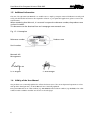
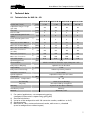
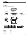
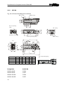
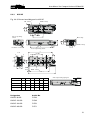
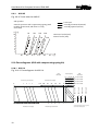
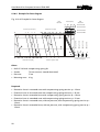
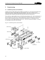
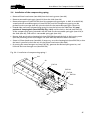
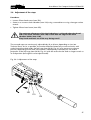
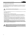
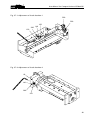
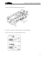
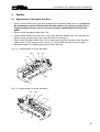
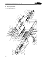
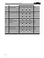
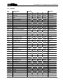
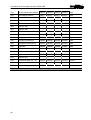
USER MANUAL
Handling Components
Compact Universal Slide
KUS
BA-100029
ENGLISH
Edition: 02/2006
®
User Manual for Compact Universal Slide KUS
Change index
Previously published editions:
Edition
Remark
Article number
08/2004
First edition
508435
02/2006
2
BA-100029
®
User Manual for Compact Universal Slide KUS
Table of contents
1
Important information ............................................................................................ 5
1.1
Introduction ....................................................................................................................5
1.2
Declaration of EU conformance (to Directive on Machines, Appendix II A) .................5
1.3
Product description and application ..............................................................................5
1.4
Dangers ..........................................................................................................................5
1.5
Additional information ...................................................................................................6
1.6
Validity of the User Manual ............................................................................................6
2
Technical data ......................................................................................................... 7
2.1
Technical data for KUS-16-..-SD .....................................................................................7
2.2
Technical data for KUS-20-...-SD ....................................................................................8
2.3
Technical data for KUS-25-...-SD ....................................................................................9
2.4
Special accessories .......................................................................................................10
2.5
Accessories ...................................................................................................................10
2.6
Dimensioned diagrams.................................................................................................11
2.6.1
KUS-16 ................................................................................................................................... 11
2.6.2
KUS-20 ................................................................................................................................... 12
2.6.3
KUS-25 ................................................................................................................................... 13
2.7
Load calculations ..........................................................................................................14
2.8
Deformations ................................................................................................................16
2.8.1
Definition of the deformations.............................................................................................. 16
2.8.2
KUS-16 ................................................................................................................................... 16
2.8.3
KUS-20 ................................................................................................................................... 16
2.8.4
KUS-25 ................................................................................................................................... 16
2.9
Travel times ..................................................................................................................17
2.9.1
KUS-16 ................................................................................................................................... 17
2.9.2
KUS-20 ................................................................................................................................... 17
2.9.3
KUS-25 ................................................................................................................................... 18
2.10 Force diagrams (KUS with compensating spring kit)...................................................18
2.10.1
KUS-16 ................................................................................................................................... 18
2.10.2
KUS-20 ................................................................................................................................... 19
2.10.3
KUS-25 ................................................................................................................................... 19
2.10.4
Example for force diagram.................................................................................................... 20
3
Commissioning...................................................................................................... 22
3.1
Installation position and installation.............................................................................22
3.2
Installation of the add-on units (Fig. 3.1-1) ..................................................................23
3.3
Setup information.........................................................................................................24
3
®
User Manual for Compact Universal Slide KUS
3.4
Installation of the compensating spring.......................................................................25
3.5
Pneumatic connection ..................................................................................................26
3.6
Adjustment of the stops...............................................................................................27
3.7
Adjustment of the shock absorbers .............................................................................28
3.8
Installation and connection of the inductive proximity switches.................................30
4
Maintenance ......................................................................................................... 32
4.1
Lubrication ....................................................................................................................32
5
Repairs .................................................................................................................. 33
5.1
Replacement of the shock absorbers...........................................................................33
6
Spare parts lists .................................................................................................... 34
6.1
KUS-16 ..........................................................................................................................35
6.2
KUS-20 ..........................................................................................................................37
6.3
KUS-25 ..........................................................................................................................39
7
General information.............................................................................................. 41
7.1
Environmental compatibility and disposal ...................................................................41
8
List of figures........................................................................................................ 42
4
®
User Manual for Compact Universal Slide KUS
1
Important information
1.1 Introduction
This User Manual describes the mechanical design, the technical data, the load limits, the
installation, the maintenance and the spare parts of the compact universal slide KUS.
1.2 Declaration of EU conformance (to Directive on Machines, Appendix II A)
Regulations and standards taken into account:
! Directive on Machines 89/392/EEC, 91/368/EEC
Manufacturer:
Montech AG
Gewerbestrasse 12
CH-4552 Derendingen
Tel. +41 (0) 32 681 55 00
Fax +41 (0) 32 682 19 77
1.3 Product description and application
Compact universal slides KUS are pneumatically operated linear units for performing regular,
linear forward and backward movements in any direction in space.
The load limits which were specified by the technical data for each slide size must be complied
with under all circumstances. Overloading can lead to faults and failure of the devices.
1.4 Dangers
The use of compact universal slides KUS in equipment is permissible only when they provide
protection by movable, separating protective devices according to EN 292-2 Section 4.2.2.3.
Failure to observe this safety measure can result in injuries due to crushing and impact,
particularly in the case of machines which start up automatically.
The stated load limits must be complied with.
Important!
During work on the device, it must be ensured that the compressed air cannot be
switched on by unauthorized persons!
5
®
User Manual for Compact Universal Slide KUS
1.5 Additional information
The aim of the present User Manual is to enable users to employ compact universal slide KUS correctly and
safely. Should further information be required in relation to your particular application, please contact the
manufacturer.
When reordering User Manuals, it is essential to quote the reference number, the product name
and serial number.
This document can be obtained from our homepage www.montech.com.
Fig. 1.5-1: Nameplate
Reference number
Product name
Serial number
Montech AG
Management
U. D. Wagner
C. Wullschleger
1.6 Validity of the User Manual
Our products are continually updated to reflect the latest state of the art and practical experience. In line
with product developments, our User Manuals are continually updated.
Every User Manual has an order number (e.g. BA-100029) and an edition number (e.g. 02/2006). The order
number and the addition number are shown on the title page.
6
®
User Manual for Compact Universal Slide KUS
2
Technical data
2.1 Technical data for KUS-16-..-SD
KUS-16-20-SD KUS-16-40-SD KUS-16-60-SD KUS-16-80-SD
Stroke (min. / max.)
[mm]
5 / 20
5 / 40
20 / 60
40 / 80
Adjustment range of stops
(per side)
[mm]
20
20
20
20
Piston Ø
[mm]
16
16
16
16
Piston rod Ø
[mm]
6
6
6
6
[kg]
4
4
4
4
[kg]
3
3
3
3
Perm. mounting mass horiz.
mhmax
Perm. mounting mass vert.
mvmax
1)
Max. stat. moment M0xmax
2)
[Nm]
15
18
21
24
Max. stat. moment M0ymax
2)
[Nm]
9
12
15
18
Max. stat. moment M0zmax
2)
[Nm]
9
12
15
18
Max. stat. force Fxmax
(at 5 bar)
2)
[N]
60
60
60
60
Max. stat. force Fymax
2)
[N]
120
130
140
150
Max. stat. force Fzmax
2)
[N]
120
130
140
150
[kg]
0.75
0.85
0.95
1.05
Unloaded weight
Operating pressure
[bar]
Drive medium
Oiled or unoiled air filtered to 5 µm, dew point < 6°C
End position damping
Hydraulic shock absorbers
Repeatability
3)
End position monitoring
4)
[mm]
Hose ø 4mm
Speed regulation
Adjustable exhaust throttle valves
5)
Sound level
Temperature
2)
3)
4)
5)
10 ... 50
Normal workshop atomsphere
Warranty
1)
< 64
< 95% (non-condensing)
Air purity
Material
[dBA]
[°C]
Rel. humidity
Installation position
< 0.01
Inductive proximity switches
Pneumatic connection
Environment:
3-6
2 years from the date of delivery
1)
Arbitrary
Aluminum, steel
For vertical applications, use compensating spring
(see Special accessories: compensating spring kits)
See load calculations
Variation of the end position with 100 successive strokes, conditions as for 5)
See Accessories
Measured at 5 bar, maximum horizontal stroke, with m=mhmax, throttled
(travel to end positions without impact)
7
®
User Manual for Compact Universal Slide KUS
2.2 Technical data for KUS-20-...-SD
KUS-20-40-SD KUS-20-80-SD KUS-20-120-SD KUS-20-160-SD
Stroke (min. / max.)
[mm]
10 / 40
10 / 80
40 / 120
80 / 160
Adjustment range of stops
(per side)
[mm]
40
40
40
40
Piston Ø
[mm]
20
20
20
20
Piston rod Ø
[mm]
8
8
8
8
[kg]
6
6
6
6
[kg]
5
5
5
5
Perm. mounting mass horiz.
mhmax
Perm. mounting mass vert.
mvmax
1)
Max. stat. moment M0xmax
2)
[Nm]
22
27
32
37
Max. stat. moment M0ymax
2)
[Nm]
18
26
34
42
Max. stat. moment M0zmax
2)
[Nm]
18
26
34
42
Max. stat. force Fxmax
(at 5 bar)
2)
[N]
90
90
90
90
Max. stat. force Fymax
2)
[N]
180
210
240
270
Max. stat. force Fzmax
2)
[N]
180
210
240
270
[kg]
1.3
1.6
1.9
2.2
Unloaded weight
Operating pressure
[bar]
Drive medium
Oiled or unoiled air filtered to 5 µm, dew point < 6°C
End position damping
Hydraulic shock absorbers
Repeatability
3)
End position monitoring
4)
[mm]
Hose ø 6mm
Speed regulation
Adjustable exhaust throttle valves
5)
Sound level
Temperature
2)
3)
4)
5)
8
10 ... 50
Normal workshop atmosphere
Warranty
1)
< 64
< 95% (non-condensing)
Air purity
Material
[dBA]
[°C]
Rel. humidity
Installation position
< 0.01
Inductive proximity switches
Pneumatic connection
Environment:
3-6
2 years from the date of delivery
1)
Arbitrary
Aluminum, steel
For vertical applications, use compensating spring
(see Special accessories: compensating spring kits)
See load calculations
Variation of the end position with 100 successive strokes, conditions as for 5)
See Accessories
Measured at 5 bar, maximum horizontal stroke, with m=mhmax, throttled
(travel to end positions without impact)
®
User Manual for Compact Universal Slide KUS
2.3 Technical data for KUS-25-...-SD
KUS-25-60-SD KUS-25-120-SD KUS-25-180-SD KUS-25-240-SD
Stroke (min. / max.)
[mm]
10 / 60
40 / 120
100 / 180
160 / 240
Adjustment range of stops
(per side)
[mm]
40
40
40
40
Piston Ø
[mm]
25
25
25
25
Piston rod Ø
[mm]
10
10
10
10
[kg]
6
10
10
10
[kg]
8
8
8
8
Perm. mounting mass horiz.
mhmax
Perm. mounting mass vert.
mvmax
1)
Max. stat. moment M0xmax
2)
[Nm]
50
62
74
86
Max. stat. moment M0ymax
2)
[Nm]
44
66
88
110
Max. stat. moment M0zmax
2)
[Nm]
44
66
88
110
Max. stat. force Fxmax
(at 5 bar)
2)
[N]
150
150
150
150
Max. stat. force Fymax
2)
[N]
300
360
420
480
Max. stat. force Fzmax
2)
[N]
300
360
420
480
[kg]
2.4
3.1
3.8
4.5
Unloaded weight
Operating pressure
[bar]
Drive medium
Oiled or unoiled air filtered to 5 µm, dew point < 6°C
End position damping
Hydraulic shock absorbers
Repeatability
3)
End position monitoring
4)
[mm]
Hose ø 6mm
Speed regulation
Adjustable exhaust throttle valves
5)
Sound level
Temperature
2)
3)
4)
5)
10 ... 50
Normal workshop atmosphere
Warranty
1)
< 64
< 95% (non-condensing)
Air purity
Material
[dBA]
[°C]
Rel. humidity
Installation position
< 0.01
Inductive proximity switches
Pneumatic connection
Environment:
3-6
2 years from the date of delivery
1)
Arbitrary
Aluminum, steel
For vertical applications, use compensating spring
(see Special accessories: compensating spring kits)
See load calculations
Variation of the end position with 100 successive strokes, conditions as for 5)
See Accessories
Measured at 5 bar, maximum horizontal stroke, with m=mhmax, throttled
(travel to end positions without impact)
9
®
User Manual for Compact Universal Slide KUS
2.4 Special accessories
Compensating spring kits:
Tension spring with clamping pin and 2 hexagon nuts for installation for vertical use:
Designation
Article No.
Compensating spring kit for KUS-16-20-SD
51631
Compensating spring kit for KUS-16-40-SD
51632
Compensating spring kit for KUS-16-60-SD
51633
Compensating spring kit for KUS-16-80-SD
51634
Compensating spring kit for KUS-20-40-SD
51635
Compensating spring kit for KUS-20-80-SD
51636
Compensating spring kit for KUS-20-120-SD
51637
Compensating spring kit for KUS-20-160-SD
51638
Compensating spring kit for KUS-25-60-SD
51639
Compensating spring kit for KUS-25-120-SD
51640
Compensating spring kit for KUS-25-180-SD
51641
Compensating spring kit for KUS-25-240-SD
51642
2.5 Accessories
Inductive proximity switches:
PNP ø 6.5 mm with LED, short-circuit-proof and with pole reversal protection, sensing distance 2
mm, can be installed flush:
Designation
Article No.
Cable length 2.5 m
504513
Cable length 5 m
504755
Pluggable
508449
Connecting cable for pluggable proximity switches:
For 3-pole proximity switch, highly flexible, screwable M8x1:
Designation
Aritcle No.
Cable length 1 m, with socket angled on one side
506488
Cable length 5 m, with socket angled on one side
504929
Cable length 10 m, with socket angled on one side
507529
10
®
User Manual for Compact Universal Slide KUS
2.6 Dimensioned diagrams
2.6.1
KUS-16
Fig. 2.6-1: Dimensioned diagram for KUS-16
M4 6 deep
Ø4H8 7 deep
40
30
4
20
20
nx40
Hole for proximity
switch
d
Pneumatic connection
15
39
39.5
12
M4 6 deep
30
10
Ø4H8 7 deep
Hole for proximity switch
a
nx40
A -A
20
20
17.5
4
30
A
40
40
60
4
M4 6 deep
40
Ø4H8 7 deep
A
10
b
m ax. c
with compensating spring
kit
b
c
d
n
q
KUS-16-20-SD
128
93
145.5
104
1
14
KUS-16-40-SD
154
119
171.5
130
2
24
KUS-16-60-SD
180
145
197.5
156
2
34
KUS-16-80-SD
206
171
223.5
182
2
44
Designation
Article No.
KUS-16-20-SD
51540
KUS-16-40-SD
51541
KUS-16-60-SD
51542
KUS-16-80-SD
51543
m ax . q
35
a
11
®
User Manual for Compact Universal Slide KUS
2.6.2
KUS-20
Fig. 2.6-2: Dimensioned diagram for KUS-20
Ø4H8 7 deep
M4 6.5 deep
30
40
4
25
25
nx50
Hole for proximity
switch
20
45
45
15
M4 6 deep
30
12
d
Pneumatic connection
Hole for proximity switch
Ø4H8 7 deep
a
A -A
25
4
M4 6.5 deep
Ø4H8 7 deep
46
A
24
30
40
74
40
4
nx50
25
10
A
b
m ax . c
KUS-20-40-SD
b
169
c
128
d
200
n
143
1
14
KUS-20-80-SD
221
180
252
195
2
24
KUS-20-120-SD
273
232
304
247
3
34
KUS-20-160-SD
325
284
356
299
3
44
Designation
Article No.
KUS-20-40-SD
51544
KUS-20-80-SD
51545
KUS-20-120-SD
51546
KUS-20-160-SD
51547
12
with compensating spring
kit
q
m ax . q
39
a
®
User Manual for Compact Universal Slide KUS
2.6.3
KUS-25
Fig. 2.6-3: Dimensioned diagram for KUS-25
M5 8 deep
Ø5H8 7 deep
40
30
4
25
50
nx100
Hole for proximity
switch
12
d
Pneumatic connection
30
15
53
53
12
M5 8 deep
30
Ø5H8 7 deep
Hole for proximity switch
a
A -A
nx100
4
4
24
50
A
96
40
40
30
25
54
M4 8
deep
A
Ø5H8 8 deep
14
b
m ax . c
b
c
d
n
q
KUS-25-60-SD
234
189
265
203
1
14
KUS-25-120-SD
318
273
349
287
2
24
KUS-25-180-SD
402
357
433
371
2
34
KUS-25-240-SD
484
439
515
453
3
44
Designation
Article No.
KUS-25-60-SD
51548
KUS-25-120-SD
51549
KUS-25-180-SD
51550
KUS-25-240-SD
51551
m ax . q
45.5
with compensating spring kit
a
13
®
User Manual for Compact Universal Slide KUS
2.7 Load calculations
The load values stated in the technical data are maximum values in the case of a single load. The
following calculations apply to the combined loads experienced in practical applications:
Fig. 2.7-1: Load calculations
Kx
Lx
Mz
My
Mx
Lz
Ly
Fy
Fz
Fx
a)
Dynamic load with horizontal use
M X = 0.001⋅ m ⋅ g ⋅ L Y
M Y = 0.001⋅ m ⋅ (g ⋅ (L X − K X ) + 25 ⋅ L Z )
M Z = 0.001⋅ m ⋅ 25 ⋅ L Y
Combined dynamic load with horizontal use:
B=
MY
MX + MZ
+
≤1
MY max (MX + MZ )max
B=
MY
MZ
+
≤1
M Y max M Z max
b) Dynamic load with vertical use
MY = 0.001⋅ m ⋅ (g + 25) ⋅ L Z
MZ = 0.001⋅ m ⋅ (g + 25) ⋅ L Y
Combined dynamic load with vertical use:
14
®
User Manual for Compact Universal Slide KUS
c)
Static load
M0X = 0.001⋅ (FY ⋅ L Z + FZ ⋅ L Y )
M0Y = 0.001⋅ (FX ⋅ L Z + FZ ⋅ (L X − K X ))
M0Z = 0.001⋅ (FX ⋅ L Y + FY ⋅ (L X − K X ))
B0 =
Combined static load:
M0 X
M0 Y
M0 Z
+
+
≤1
M0X max M0Y max M0 Z max
B, B0
Load factor: Must not exceed the value 1!
Mi, M0i
Existing moments [Nm]
Mimax, M0imax
Max. permissible moments [Nm] (see table)
m
Mounting mass [kg]
LX, LY, LZ
Distance of center of gravity of the moving mass or force application
distances [mm]
FX, FY, FZ
Active forces [N], for max. values, see "Technical data"
KX
Constant according to table [mm]
g
Acceleration due to gravity (9.81 m/s )
2
Horizontal use
Vertical use
Static
KX
[mm]
MYmax
[Nm]
(MX+MZ)max
[Nm]
MYmax
[Nm]
MZmax
[Nm]
M0Xmax
[Nm]
M0Ymax
[Nm]
M0Zmax
[Nm]
KUS-16-20-SD
33
9
12
9
9
15
9
9
KUS-16-40-SD
36
10
13
10
10
18
12
12
KUS-16-60-SD
39
11
14
11
11
21
15
15
KUS-16-80-SD
42
12
15
12
12
24
18
18
KUS-20-40-SD
41
14
18
14
14
22
18
18
KUS-20-80-SD
47
17
20
15
15
27
26
26
KUS-20-120-SD
53
20
22
16
16
32
34
34
KUS-20-160-SD
59
23
24
17
17
37
42
42
KUS-25-60-SD
61
29
36
26
26
50
44
44
KUS-25-120-SD
73
36
42
28
28
62
66
66
KUS-25-180-SD
85
43
48
30
30
74
88
88
KUS-25-240-SD
96
50
54
32
32
86
110
110
On installation of a projecting load (direction Lz) on the end plate, it is essential
to provide additional fastening on the slide to prevent vibrations (see Setup
information)!
15
®
User Manual for Compact Universal Slide KUS
2.8 Deformations
2.8.1
Definition of the deformations
2.8.2
Fy
Fz
fy
fz
Fig. 2.8-1: Definition of the deformations
KUS-16
Fig. 2.8-2: Deformations for KUS-16
fz [mm]
KUS-16-80
0.08
0.06
KUS-16-60
0.04
KUS-16-40
KUS-16-20
0.02
20
2.8.3
40
60
fy [mm]
0.06
0.02
Fz [N]
80
KUS-16-80
KUS-16-60
KUS-16-40
KUS-16-20
0.04
20
40
60
80
Fy [N]
KUS-20
Fig. 2.8-3: Deformations for KUS-20
fz [mm]
KUS-20-160
0.20
fy [mm]
0.15
KUS-20-120
0.10
KUS-20-160
KUS-20-120
KUS-20-80
KUS-20-40
0.10
KUS-20-80
KUS-20-40
0.05
30
2.8.4
0.15
60
90
120
0.05
Fz [N]
30
60
90
120
Fy [N]
KUS-25
Fig. 2.8-4: Deformations for KUS-25
fz [mm]
KUS-25-240
0.40
fy [mm]
0.30
KUS-25-180
0.20
KUS-25-120
KUS-25-60
0.10
50
16
100
150
200
Fz [N]
0.20
KUS-25-240
KUS-25-180
KUS-25-120
KUS-25-60
0.10
50
100
150
200
Fy [N]
®
User Manual for Compact Universal Slide KUS
2.9 Travel times
2.9.1
KUS-16
Fig. 2.9-1: Travel times for KUS-16
with p=5 bar
horizontal
vertically downward (extend)
vertically upward (retract)
Vertical operation with compensating spring (with
m=0 kg untensioned, with m=mvmax fully
tensioned)
m [kg ]
Horizontal stroke [mm]
2 0 40 60 80
4
20
3
40
60
80
Vertical stroke [mm]
2
1
0.05
2.9.2
0.15
0.1
0.2
0.25
0 .3 t [s]
KUS-20
Fig. 2.9-2: Travel times for KUS-20
with p=5 bar
Vertical operation with compensating spring (with
m=0 kg untensioned, with m=mvmax fully
tensioned)
horizontal
vertically downward (extend)
vertically upward (retract)
m [kg ]
80
40
6
40
5
Horizontal stroke [mm]
1 20 16 0
80 1 2 0
Vertical stroke [mm]
16 0
4
3
2
1
0.1
0.2
0.3
0.4
0 .5
t [s]
17
®
User Manual for Compact Universal Slide KUS
2.9.3
KUS-25
Fig. 2.9-3: Travel times for KUS-25
with p=5 bar
horizontal
vertically downward (extend)
vertically upward (retract)
Vertical operation with compensating spring (with
m=0 kg untensioned, with m=mvmax fully
tensioned)
m [kg ]
120
60
10
9
8
7
6
5
4
3
2
1
60
0 .1
0.2
180
120
0 .3
240
180
Horizontal stroke [mm]
Vertical stroke [mm]
240
0.4
0.6 t [s]
0 .5
2.10 Force diagrams (KUS with compensating spring kit)
2.10.1 KUS-16
Fig. 2.10-1: Force diagrams for KUS-16
0
20
40
4
60
5
80
6
120
100
Retraction force [N]
18
120
100
80
60
6
5
40
4
Extension pressure bar
20
K U S-16-20
0 10 20 30 40
K U S -16-40
0
K U S -16-60
20 40 60
0 0 20
60 80
K U S -16-80
K U S-16-20
3
0 5 10 15 20
K U S-16-40
0
fully
extended
K U S-16-60
Extension force [N]
Retraction pressure [bar]
Position [mm]
K U S-16-80
fully
retracted
4
4
4
4
24
19
14
9
44
34
24
14
3
Compensating spring tension q [mm]
(see dimensioned diagram)
®
User Manual for Compact Universal Slide KUS
2.10.2 KUS-20
Fig. 2.10-2: Force diagrams for KUS-20
fully
retracted
Position [mm]
fully
extended
0 10 20 30 40 K U S-20-40
0 20 40 60 80 K U S -2 0 -8 0
40 80 12 0 K U S -2 0 -120
0
3
4
5
6
16 0 14 0 12 0 10 0 80 60 40 20
20 40 60 80 10 0 12 0 14 0 16 0 18 0
5
6
Retraction force [N]
4
0 0 40
12 0 16 0 K U S -2 0 -160
3
K U S-20-40
0
K U S-20-80
0
K U S-20-120
Extension force [N]
K U S-20-160
Retraction pressure [bar]
4
24
44
4
19
34
4
14
24
4
9
14
Compensating spring tension q [mm]
(see dimensioned diagram)
Extension pressure [bar]
2.10.3 KUS-25
Fig. 2.10-3: Force diagrams for KUS-25
fully
retracted
0
40
80
5
6
240
12 0 16 0 2 0 0 2 4 0 2 8 0
Retraction force [N]
2 0 0 16 0 12 0
6
5
40
80
4
Extension pressure [bar]
3
40
60
0
40
8 0 12 0
K U S -2 5 -6 0
K U S -2 5 -12 0
0 40
12 0 18 0 K U S -2 5 -18 0
0 0 40
2 0 0 2 4 0 K U S -2 5 -2 4 0
K U S -25 -6 0
4
20
K U S -25 -12 0
3
0
K U S -25 -18 0
0
fully
extended
K U S -25 -2 4 0
Extension force [N]
Retraction pressure [bar]
Position [mm]
4
24
44
4
19
34
4
14
24
4
9
14
Compensating spring tension q [mm]
(see dimensioned diagram)
19
®
User Manual for Compact Universal Slide KUS
2.10.4 Example for force diagram
Fig. 2.10-4: Example for force diagram
0
40
80
4
5
6
240 200 16 0 12 0
12 0 16 0 200 240 280
Retraction force [N]
6
5
20
40
0
40
80 12 0
K U S -2 5 -12 0
12 0 18 0
K U S -2 5 -18 0
0 40
80
4
Extension pressure [bar]
40
3
0 0 40
60
200 240 KU S-25-240
4
24
44
4
19
34
K U S-25-12 0
3
KU S-25-60
0
K U S-25-18 0
0
fully
extended
K U S-25-240
Extension force [N]
Retraction pressure [bar]
Position [mm]
4
14
24
K U S-25-60
fully
retracted
4
9
14
Compensating spring tension q [mm]
(see dimensioned diagram)
Given:
! KUS-25-120 with compensating spring kit
! Stroke:
70 mm (vertical, extend downward)
! Pressure:
5 bar
! Mounting mass: 6 kg
Required:
! Retraction force in retracted state with compensating spring tension q = 19 mm
! Extension force in retracted state with compensating spring tension q = 19 mm
! Retraction force in extended state with compensating spring tension q = 19 mm
! Extension force in extended state with compensating spring tension q = 19 mm
! Retraction force in retracted state, without pressure, with compensating spring tension q =
19 mm
! Retraction force in extended state, without pressure, with compensating spring tension q =
19 mm
20
®
User Manual for Compact Universal Slide KUS
1.
Determine positions for KUS-25-120 (point a and point b): for the 70 mm stroke, the
extended position is reduced by 40 mm (= max. stop adjustment range per side), gives
position 80 mm, and additionally the retracted position is reduced by 10 mm (120-40-70 =
10 mm). From points a and b, draw the lines 1 and 2 vertically downward.
2.
Mark compensating spring tension q = 19 mm for KUS-25-120 (point c) and draw horizontal
line 3 to edge of diagram (gives point d).
3.
From point d, draw line 4 parallel to the predetermined lines. The point of intersection with
line 1 gives point e and the point of intersection with line 2 give point f.
4.
From point e, draw horizontal line 5 to the left. The point of intersection with extension
pressure 5 bar gives point g, the point of intersection with retraction pressure 5 bar gives
point h and the point of intersection with retraction pressure 0 bar gives point i.
5.
From g, draw vertical line 6 upward, gives an extension force in the retracted state of
188 N. Adding the installation mass of 60 N to this gives 248 N.
6.
From point h, draw vertical line 7 downward, gives a retraction force in the retracted state
of 194 N. Subtracting the installation mass of 60 N from this gives 134 N.
7.
From point i, draw vertical line 8 downward, gives a retraction force at atmospheric
pressure in the retracted state of 20 N, i.e. the installation mass of 60 N is not held in the
upper end position on loss of pressure.
8.
From point f, draw horizontal line 9 to the left. The point of intersection with extension
pressure 5 bar gives point k, the point of intersection with retraction pressure 5 bar gives
point l and the point of intersection with retraction pressure 0 bar gives point m.
9.
From point k, draw vertical line 10 upward, gives an extension force in the extended state
of 161 N. Adding the installation mass of 60 N to this gives 221 N.
10. From point l, draw vertical line 11 downward, gives a retraction force in the extended
state of 222 N. Subtracting the installation mass of 60 N from this gives 162 N.
11. From point m, draw line 12 downward, gives a retraction force at atmospheric pressure in
the extended state of 47 N, i.e. the installation mass of 60 N is not retracted from the
lower end position on loss of pressure!
21
®
User Manual for Compact Universal Slide KUS
3
Commissioning
3.1 Installation position and installation
Compact universal slides KUS can be installed in any position. As a rule, the housing (item 10) is
fixed and the stroke is performed by the slide (item 20). In the case of vertical use, it is
necessary to provide a compensating spring (see Special accessories), which ensures uniform
movement and an optimum cycle time even with the maximum mounting mass.
The installation is performed by means of Quick-Set fixing elements (SLL-..-40) on the dovetail of
the housing (item 10) or by means of the threaded holes and positioning holes on the housing
(item 10). With installation by means of Quick-Set fixing elements, it is advisable to fix the
housing (item 10) with two clamping elements SLL-..-40 (use of the dovetail length, i.e. fixing as
far as possible at the ends of the housing).
Fig. 3.1-1: Installation position and installation
SLR-15-40
20
SLL-55-40
70
10
SLR-15-40
SLL-20-40
SLL-55-40
SLL-20-40
22
SLL-55-40
®
User Manual for Compact Universal Slide KUS
Fig. 3.1-2: Installation position and installation
With the use of Quick-Set fixing elements, it is essential to ensure that the fixing
elements do not project beyond the edge of the housing at the front!
3.2 Installation of the add-on units (Fig. 3.1-1)
Provided that the permissible loads are complied with, any add-on units can be fixed to the KUS
slide.
The add-on units are installed by means of Quick-Set fixing elements (SLL-..-40 or SLR-15-40) on
the dovetail fitting mounted on the slide (item 20) or on the end plate (item 70) or by means of
the threaded holes and positioning holes on slide (item 20) and end plate (item 70). Fixing on
the end plate (item 70) and on the slide (item 20) always results in improved rigidity and a
reduction in the vibrations! (Also see section "Setup information").
When fixing add-on units, the static load limits of the KUS slides must be
observed with respect to the tightening torques!
23
®
User Manual for Compact Universal Slide KUS
3.3 Setup information
On installing a projecting load (direction Lz) on the end plate, it is essential to provide additional
fixing on the slide in order to prevent vibrations! By using Quick-Set elements, such fixing can be
realized easily and quickly.
E.g. feeder with revolver head:
A bracket KW-40 with two clamping elements SLL-55-40 is used for additional fixing for the
vertical KUS.
Fig. 3.3-1: Mounting example (feeder with revolver head)
SLL-55-40
KW-40
KUS
KUS
SLL-55-40
24
®
User Manual for Compact Universal Slide KUS
3.4 Installation of the compensating spring
! Remove fillister head screw (item 440) from the housing cover (item 60).
! Remove retractable spring pin (item 210) from the slide (item 20).
! Remove hexagon nut (item EAF/30) from the compensating spring kit. In KUS-16 and KUS-20,
screw back the second hexagon nut (item EAF/30) until the compensating spring can be
pushed into the carriage (item 20) up to the hole for the retractable spring pin (item 210).
! Extend slide and insert compensating spring kit into the hole on the slide (item 20) (note
position of clamping bolt (item EAF/20)! Fig. 3.4-2) until the hole in the tab (item EAF/10)
of the compensating spring coincides with the hole for the retractable spring pin (item 210) in
the slide (item 20), and screw in retractable spring pin (item 210).
! Retract slide, passing the clamping bolt (item EAF/20) through the hole in the housing cover
(item 60) and fixing it with the hexagon nut (item EAF/30) which has been removed.
! Screw in fillister head screw (item 440; if necessary, turn the clamping bolt (item EAF/20) so that
the bevel is parallel to the hole axis for the fillister head screw (item 440).
! By turning the outer hexagon nut (item EAF/30), generate the desired spring tension, and
lock with the inner hexagon nut (item EAF/30).
Fig. 3.4-1: Installation of compensating spring 1
210
20
EAF/10
EAF/30
EAF/20
EAF/30
440
60
25
®
User Manual for Compact Universal Slide KUS
Fig. 3.4-2: Installation of compensating spring 2
EAF/20
3.5 Pneumatic connection
The adjustable exhaust throttles (item 500) have pluggable air connections, and the respective
hose diameters are shown in the technical data.
Extend slide:
The slide (item 20) is extended via the connection "A".
Retract slide:
The slide (item 20) is retracted via the connection "B".
Fig. 3.5-1: Pneumatic connection
A
20
B
500
500
B
A
26
®
User Manual for Compact Universal Slide KUS
3.6 Adjustment of the stops
Procedure:
! Loosen fillister head screw (item 350).
! Screw in or unscrew shock absorber (item 120) using a screwdriver or using a hexagon socket
wrench.
! Tighten fillister head screw (item 350).
The maximum adjustment of the shock absorbers is achieved when the thread
end of the shock absorber (item 120) is flush with the edge of the shock
absorber bolder (item 110)!
Keep hands and tools out of the way during travel!
The two end stops are continuously adjustable by 20 or 40 mm, depending on size (see
Technical Data). As far as possible, the stroke should be limited only at one end since, with
stroke limitation at both ends, the ball cage (item 30/20; Fig. 6-1) may move to an extreme
position, depending on the load. If the stroke is subsequently increased, this can lead to
projection of the ball cage (item 30/20; Fig. 6-1) with the result that the slide no longer travels to
its end position (ball cage has to be repositioned)!
Fig. 3.6-1: Adjustment of the stops
350
110
120
27
®
User Manual for Compact Universal Slide KUS
3.7 Adjustment of the shock absorbers
The travelling speed, the mounting mass and the operating pressure influence the energy to be
absorbed by the shock absorbers. The optimum adjustment, i.e. that which gives the shortest
travel time with given influencing variables, is achieved by matching exhaust air throttling and
shock absorber setting.
Keep hands and tools out of the way during travel!
! Set up KUS in desired position (with vertical use, install compensating spring, see "Installation
of the compensating spring").
! Mount add-on units.
! Close exhaust throttles (item 500) about 4 to 5 turns.
! Set end position damping to maximum damping (basic setting): loosen threaded pin (item
390) about a quarter turn so that the damping screw (item 150) can be turned but the
clamping sleeve (item 140) is still held, and screw in damping screw (item 150) fully. Tighten
threaded pin (item 390).
! The optimum settings are obtained if the slide with the installed load travels to the end
position without causing an impact or without any visible retardation. If an impact occurs at
the end position with the existing settings, the corresponding exhaust throttle (item 500)
must be further closed. If the slide travels to the end position with a visible retardation, the
exhaust throttle (item 500) can be opened slightly and/or the damping screw (item 150) can
be unscrewed slightly.
Important: When tightening the threaded pin (item 390), ensure that the collar of the
clamping sleeve (item 140) rests against the front stop (item 130) or against the housing
(item 60). The minimum damping is obtained when the damping screw (item 150) is flush
with the clamping sleeve (item 140) (Fig. 3.7-2).
Travel to the end positions with impacts has an adverse effect on the life of the
KUS!
By setting the maximum travel time permissible in the process, the KUS slide is
protected and the service life is increased.
28
®
User Manual for Compact Universal Slide KUS
Fig. 3.7-1: Adjustment of shock absorber 1
500
500
150
140
130
390
Fig. 3.7-2: Adjustment of shock absorber 2
60
140
390
150
29
®
User Manual for Compact Universal Slide KUS
3.8 Installation and connection of the inductive proximity switches
The inductive proximity switches to be installed must fulfil the following conditions:
! Sensing distance:
2 mm
! Capable of being installed flush
! Housing diameter:
6.5 mm
! Minimum housing length (Ø 6.5):
15 mm
The proximity switches are installed by pushing into the corresponding hole in the housing cover
(item 60) or in the front stop (item 130) up to the bottom of the hole. They are fixed by
tightening the clamping screw (item 190).
Connecting cable to pluggable proximity switches:
With the use of pluggable proximity switches, it is essential to use connecting cables with
angled socket, owing to the limited space available at the front position scan.
To ensure that forces can never act on the proximity switches, the connecting cables should
always be provided with tension relief devices!
Fig. 3.8-1: Installation of inductive proximity switch 1
190
60
30
®
User Manual for Compact Universal Slide KUS
Fig. 3.8-2: Installation of inductive proximity switch 2
130
190
The electrical connection is made according to the following diagram:
Fig. 3.8-3: Connection of the inductive proximity switch
DC voltage (DC)
brown
black
blue
DC voltage (DC)
brown
black
blue
31
®
User Manual for Compact Universal Slide KUS
4
Maintenance
4.1 Lubrication
Exclusively Klüber oil "Paraliq P460" (Montech Art No. 504721) may be used as a lubricant.
! Lubrication interval:
800 operating hours
! Lubricating points:
Apply lubricant to 4 positions "C" directly on the guide track on the
guide rails (item 30/10) and distribute by retracting and extending the slide
several times (repeat procedure 2-3 times). In the case of short strokes, it is
advisable also to allow a little lubricant to flow between the guide rails
(item 30/10) on both sides in the middle of the cage (item 30/20). (Fig. 4.12).
Clean guide rails prior to lubrication!
Fig. 4.1-1: Lubrication 1
30/10
C
C
30/10
Fig. 4.1-2: Lubrication 2
30/10
30/10
30/20
C
30/10
C
30/10
32
®
User Manual for Compact Universal Slide KUS
5
Repairs
5.1 Replacement of the shock absorbers
! Loosen fillister head screws (item 340) on one shock absorber holder (item 110). Important:
On simultaneous removal of both shock absorber holders, the extension stroke will no
longer be limited! In the event of excessive extension, individual balls fall out of the
guide!
! Remove shock absorber holder (item 110).
! Loosen fillister head screw (item 350) in the shock absorber holder (item 110) removed and
replace shock absorber (item 120) (note direction of screwing in!).
! Mount shock absorber holder (item 110) on slide (item 20), positioning the shock absorber
holder (item 110) by tapping on the surface "A" on the slide (item 20), and screw tight.
! Repeat procedure for replacing the second shock absorber.
Fig. 5.1-1: Replacement of shock absorber 1
340 120
340
110
20
350
A
Fig. 5.1-2: Replacement of shock absorber 2
340
340
110
120
20
350
A
33
34
80
200/30
200/20
410
160
150
180
190
40
200/40
200/30
430
30/40
30/20
380
200/10
390 130
30/10
30/30
410
70
100
320
30/10
470
140
400
450
300
10
50
900
450
310
90
200/40
110
350
460
120
340
110
350
200/50
200/30
EAF
460
460
140
340
330
120
EAF
500
440
150
190
180
390
60
6
420
170
360 470 370
20
210
User Manual for Compact Universal Slide KUS
®
Spare parts lists
Fig. 6-1: Exploded drawing
®
User Manual for Compact Universal Slide KUS
6.1 KUS-16
No.
Designation
Item No.
Material
KUS-16
-20-SD
-40-SD
-60-SD
-80-SD
10
Housing
51426
51427
51428
51429
Aluminum
20
Slide
51453
51454
51455
51456
Aluminum
30*
Guide complete
51577
51578
51579
51580
30/10*
Guide rail
51364
51365
51366
51367
Steel
30/20*
Ball cage
51376
51377
51378
51379
Steel
30/30*
Ball
508414
508414
508414
508414
Steel
30/40*
Felt wick
51576
51576
51576
51576
Wool felt
40
Piston rod with piston
51536
51537
51538
51539
Steel/Bronze
50
Cylinder tube
51465
51466
51467
51468
Steel
60
Housing cover
51405
51405
51405
51405
Aluminum
70
End plate
51441
51441
51441
51441
Aluminum
80
Sealing bush front
51388
51388
51388
51388
Bronze
90
Sealing bush rear
51391
51391
51391
51391
Aluminum
100
Cylinder cover
51408
51408
51408
51408
Steel
110
Shock absorber holder
51397
51397
51397
51397
Aluminum
120*
Shock absorber with stop
nut
51533
51533
51533
51533
Steel/Various
130
Stop front
51394
51394
51394
51394
Aluminum
140
Clamping sleeve
51403
51403
51403
51403
Steel
150
Damping screw
51444
51444
51444
51444
Steel
160
Piston rod nut
51438
51438
51438
51438
Steel
170
Washer
51517
51517
51517
51517
Steel
180
Clamping piece
47906
47906
47906
47906
Steel
190
Clamping screw
47904
47904
47904
47904
Steel
200*
Sealing set
508423
508423
508423
508423
200/10* Piston packing
504971
504971
504971
504971
NBR
200/20* Grooved ring
506102
506102
506102
506102
PUR
200/30* O-ring
505987
505987
505987
505987
NBR
200/40* O-ring
501233
501233
501233
501233
NBR
200/50* O-ring
503101
503101
503101
503101
NBR
210
Retraction spring pin
51446
51446
51446
51446
Steel
300
Fillister head screw M3x25 508119
508119
508119
508119
Steel
35
®
User Manual for Compact Universal Slide KUS
310
Fillister head screw M3x8
508470
508470
508470
508470
Steel
320
Threaded pin M4x5
502640
502640
502640
502640
Steel
330
Fillister head screw M4x14 508472
508472
508472
508472
Steel
340
See No. 330
350
See No. 310
360
Fillister head screw M4x12 502506
502506
502506
502506
Steel
370
-
380
Fillister head screw M4x8
502522
502522
502522
502522
Steel
390
See No. 320
400
Straight pin ø2.5h6x8
506443
506443
506443
506443
Steel
410
Straight pin ø3h6x10
502020
502020
502020
502020
Steel
420
Hexagon nut M5 x 0.6d
505266
505266
505266
505266
Steel
430
Expander
502698
502698
502698
502698
Steel
440
Fillister head screw M4x12 508412
508412
508412
508412
Steel
450
Ribbed washer M3
505385
505385
505385
505385
Steel
460
Ribbed washer M4
502606
502606
502606
502606
Steel
470
See No. 460
500
Exhaust throttle M5 ø4
505023
505023
505023
505023
Various
900
Type plate
41620
41620
41620
41620
Polyester
EAF
Compensating spring kit
51631
51632
51633
51634
Steel
* The marked items are wearing parts and are available from stock.
36
®
User Manual for Compact Universal Slide KUS
6.2 KUS-20
No.
Designation
Item No.
Material
KUS-20
-40-SD
-80-SD
-120-SD -160-SD
10
Housing
51430
51431
51432
51433
Aluminum
20
Slide
51457
51458
51459
51460
Aluminum
30*
Guide complete
51581
51582
51583
51584
30/10*
Guide rail
51368
51369
51370
51371
Steel
30/20*
Ball cage
51380
51381
51382
51383
Steel
30/30*
Ball
508414
508414
508414
508414
Steel
30/40*
Felt wick
51576
51576
51576
51576
Wool felt
40
Piston rod with piston
51552
51553
51554
51555
Steel/Bronze
50
Cylinder tube
51469
51470
51471
51472
Steel
60
Housing cover
51406
51406
51406
51406
Aluminum
70
End plate
51442
51442
51442
51442
Aluminum
80
Sealing bush front
51389
51389
51389
51389
Bronze
90
Sealing bush rear
51392
51392
51392
51392
Aluminum
100
Cylinder cover
51409
51409
51409
51409
Steel
110
Shock absorber holder
51398
51398
51398
51398
Aluminum
120*
Shock absorber with stop
nut
51534
51534
51534
51534
Steel/Various
130
Stop front
51395
51395
51395
51395
Aluminum
140
Clamping sleeve
51404
51404
51404
51404
Steel
150
Damping screw
51445
51445
51445
51445
Steel
160
Piston rod nut
51439
51439
51439
51439
Steel
170
Washer
51518
51518
51518
51518
Steel
180
Clamping piece
47906
47906
47906
47906
Steel
190
Clamping screw
47904
47904
47904
47904
Steel
200*
Sealing set
508424
508424
508424
508424
200/10* Piston packing
504972
504972
504972
504972
NBR
200/20* Grooved ring
506103
506103
506103
506103
PUR
200/30* O-ring
505988
505988
505988
505988
NBR
200/40* O-ring
505574
505574
505574
505574
NBR
200/50* O-ring
503101
503101
503101
503101
NBR
210
Retraction spring pin
51447
51447
51447
51447
Steel
300
Fillister head screw M3x25 508119
508119
508119
508119
Steel
37
®
User Manual for Compact Universal Slide KUS
310
Fillister head screw M3x12 502504
502504
502504
502504
Steel
320
Theaded pin M4x10
508416
508416
508416
508416
Steel
330
Fillister head screw M4x16 502509
502509
502509
502509
Steel
340
See No. 330
350
Fillister head screw M3x8
508470
508470
508470
508470
Steel
360
Fillister head screw M5x14 502513
502513
502513
502513
Steel
370
-
380
Fillister head screw M4x10 508471
508471
508471
508471
Steel
390
Threaded pin M4x5
502640
502640
502640
502640
Steel
400
Straight pin ø4h6x12
502035
502035
502035
502035
Steel
410
See No. 400
420
Hexagon nut M6 x0.5d
508415
508415
508415
508415
Steel
430
Expander
506001
506001
506001
506001
Steel
440
Fillister head screw M4x12 508412
508412
508412
508412
Steel
450
Ribbed washer M3
505385
505385
505385
505385
Steel
460
Ribbed washer M4
502606
502606
502606
502606
Steel
470
Ribbed washer M5
505254
505254
505254
505254
Steel
500
Exhaust throttle 1/8" ø6
505016
505016
505016
505016
Various
900
Type plate
41620
41620
41620
41620
Polyester
EAF
Compensating spring kit
51635
51636
51637
51638
Steel
* The marked items are wearing parts and are available from stock.
38
®
User Manual for Compact Universal Slide KUS
6.3 KUS-25
No.
Designation
Item No.
Material
KUS-25
-60-SD
-120-SD -180-SD -240-SD
10
Housing
51434
51435
51436
51437
Aluminum
20
Slide
51461
51462
51463
51464
Aluminum
30*
Guide complete
51585
51586
51587
51588
30/10*
Guide rail
51372
51373
51374
51375
Steel
30/20*
Ball cage
51384
51385
51386
51387
Steel
30/30*
Ball
508414
508414
508414
508414
Steel
30/40*
Felt wick
51576
51576
51576
51576
Wool felt
40
Piston rod with piston
51556
51557
51558
51559
Steel/Bronze
50
Cylinder tube
51473
51474
51475
51476
Steel
60
Housing cover
51407
51407
51407
51407
Aluminum
70
End plate
51443
51443
51443
51443
Aluminum
80
Sealing bush front
51390
51390
51390
51390
Bronze
90
Sealing bush rear
51393
51393
51393
51393
Aluminum
100
Cylinder cover
51410
51410
51410
51410
Steel
110
Shock absorber holder
51399
51399
51399
51399
Aluminum
120*
Shock absorber with stop
nut
51535
51535
51535
51535
Steel/Various
130
Stop front
51396
51396
51396
51396
Aluminum
140
Clamping sleeve
51404
51404
51404
51404
Steel
150
Damping screw
51445
51445
51445
51445
Steel
160
Piston rod nut
51440
51440
51440
51440
Steel
170
Washer
51519
51519
51519
51519
Steel
180
Clamping piece
47906
47906
47906
47906
Steel
190
Clamping screw
47904
47904
47904
47904
Steel
200*
Sealing set
508425
508425
508425
508425
200/10* Piston packing
504973
504973
504973
504973
NBR
200/20* Grooved ring
508419
508419
508419
508419
PUR
200/30* O-ring
508418
508418
508418
508418
NBR
200/40* O-ring
503114
503114
503114
503114
NBR
200/50* O-ring
506130
506130
506130
506130
NBR
210
Retraction spring pin
51448
51448
51448
51448
Steel
300
Fillister head screw M4x25 508083
508083
508083
508083
Steel
39
®
User Manual for Compact Universal Slide KUS
310
Fillister head screw M4x18 508473
508473
508473
508473
Steel
320
Threaded pin M4x8
508417
508417
508417
508417
Steel
330
Fillister head screw M5x16 502512
502512
502512
502512
Steel
340
Fillister head screw M5x20 502515
502515
502515
502515
Steel
350
Fillister head screw M4x10 508471
508471
508471
508471
Steel
360
See No. 340
370
See No. 330
380
Fillister head screw M4x12 502506
502506
502506
502506
Steel
390
Threaded pin M4x5
502640
502640
502640
502640
Steel
400
Straight pin ø4h6x12
502035
502035
502035
502035
Steel
410
Straight pin ø5h6x16
502048
502048
502048
502048
Steel
420
Hexagon nut M8 x0.5d
505253
505253
505253
505253
Steel
430
Expander
508068
508068
508068
508068
Steel
440
Fillister head screw M4x12 508412
508412
508412
508412
Steel
450
Ribbed washer M4
502606
502606
502606
502606
Steel
460
Ribbed washer M5
505254
505254
505254
505254
Steel
470
See No. 460
500
Exhaust throttle 1/8" ø6
505016
505016
505016
505016
Various
900
Type plate
41620
41620
41620
41620
Polyester
EAF
Compensating spring kit
51639
51640
51641
51642
Steel
* The marked items are wearing parts and are available from stock.
40
®
User Manual for Compact Universal Slide KUS
7
General information
7.1 Environmental compatibility and disposal
Materials used
! Aluminum
! Steel
! Bronze
! Wool fiber
! PUR (Polyurethane)
! NBR (Acrylonitrile-butadiene rubber)
! Polyester
Surface refinement
! Anodic oxidation of aluminum
! Nickel-plating of steel
Forming processes
! Profile extrusion of aluminum
! Material-removing processing of metals
! Injection molding of PUR seals
! Compression molding of NBR seals
Emissions during operation
! None
During operation of the equipment with oiled air, it is advisable to return the exhaust air into the
atmosphere via an oil separator/oil filter.
Disposal
Compact universal slides (KUS) that are no longer in use are to be dismantled and recycled
according to the type of material. The type of material for each part is stated in the spare parts
lists. Any non-recyclable material is to be disposed of properly according to the materials.
41
®
User Manual for Compact Universal Slide KUS
8
List of figures
Fig. 1.5-1: Nameplate ....................................................................................................................... 6
Fig. 2.6-1: Dimensioned diagram for KUS-16................................................................................. 11
Fig. 2.6-2: Dimensioned diagram for KUS-20................................................................................. 12
Fig. 2.6-3: Dimensioned diagram for KUS-25................................................................................. 13
Fig. 2.7-1: Load calculations ........................................................................................................... 14
Fig. 2.8-1: Definition of the deformations...................................................................................... 16
Fig. 2.8-2: Deformations for KUS-16 .............................................................................................. 16
Fig. 2.8-3: Deformations for KUS-20 .............................................................................................. 16
Fig. 2.8-4: Deformations for KUS-25 .............................................................................................. 16
Fig. 2.9-1: Travel times for KUS-16................................................................................................. 17
Fig. 2.9-2: Travel times for KUS-20................................................................................................. 17
Fig. 2.9-3: Travel times for KUS-25................................................................................................. 18
Fig. 2.10-1: Force diagrams for KUS-16 ......................................................................................... 18
Fig. 2.10-2: Force diagrams for KUS-20 ......................................................................................... 19
Fig. 2.10-3: Force diagrams for KUS-25 ......................................................................................... 19
Fig. 2.10-4: Example for force diagram.......................................................................................... 20
Fig. 3.1-1: Installation position and installation.............................................................................. 22
Fig. 3.1-2: Installation position and installation.............................................................................. 23
Fig. 3.3-1: Mounting example (feeder with revolver head)............................................................ 24
Fig. 3.4-1: Installation of compensating spring 1 ........................................................................... 25
Fig. 3.4-2: Installation of compensating spring 2 ........................................................................... 26
Fig. 3.5-1: Pneumatic connection ................................................................................................... 26
Fig. 3.6-1: Adjustment of the stops................................................................................................ 27
Fig. 3.7-1: Adjustment of shock absorber 1................................................................................... 29
Fig. 3.7-2: Adjustment of shock absorber 2................................................................................... 29
Fig. 3.8-1: Installation of inductive proximity switch 1................................................................... 30
42
®
User Manual for Compact Universal Slide KUS
Fig. 3.8-2: Installation of inductive proximity switch 2................................................................... 31
Fig. 3.8-3: Connection of the inductive proximity switch .............................................................. 31
Fig. 4.1-1: Lubrication 1 .................................................................................................................. 32
Fig. 4.1-2: Lubrication 2 .................................................................................................................. 32
Fig. 5.1-1: Replacement of shock absorber 1................................................................................. 33
Fig. 5.1-2: Replacement of shock absorber 2................................................................................. 33
Fig. 6-1: Exploded drawing ............................................................................................................ 34
43
MONTECH AG
Gewerbestrasse 12, CH-4552 Derendingen
Fon +41 32 681 55 00, Fax +41 32 682 19 77
[email protected], www.montech.com