1
FIO2
User Manual
ENGLISH
Electronics and Integrated Systems Division – San Pietro Mosezzo (NO) - Italy
5.4
5.4.1
Process connections
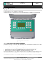
Removing the cover of the wiring compartment
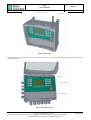
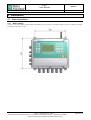
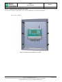
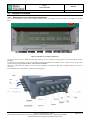
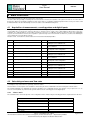
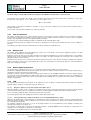
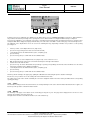
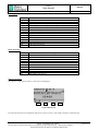
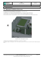
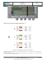
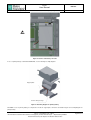
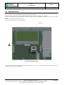
The removal of the plastic cover placed on the wiring compartment allows accessing the connection terminals as described in the following
figure:
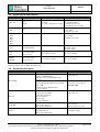
Figure 22 Terminals of the wiring compartment
The Pu1, Pd and T sensors are always present and the terminals are not accessible by removing only the cover described in the previous
paragraph.
If requested upon order, FIO 2.0 can also be supplied with the factory-wired PAux1 and PAux2 sensors; otherwise stick to the procedure
described under paragraph "MOUNTING OF THE AUXILIARY SENSORS".
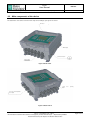
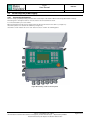
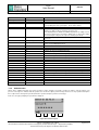
FIO 2.0 is provided with cable glands to assure the device IP tightness, provided that cables with a maximum diameter of 7 mm are
connected.
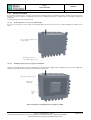
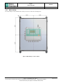
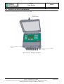
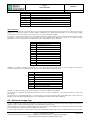
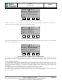
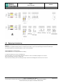
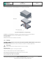
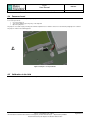
The arrangement of the cable glands is shown in the following picture:
Figure 23 Arrangement of cable glands
FIO 2.0 - User Manual – Ed .0 Rev 5
The information contained in this document is the property of Pietro Fiorentini S.p.A. – Reproduction prohibited
The technical data may be subject to modification without notice
Page 27 of 74