1
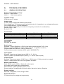
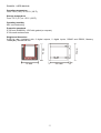
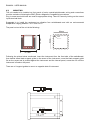
EMA96N ELECTRICAL MULTIFUNCTION ANALYZERS User Manual IM 121-U v. 4.3 EMA96N IM121-U v4.2.doc EMA96N - USER MANUAL Information in this document is subject to change without notice and does not represent a commitment on the part of Contrel Elettronica Srl. This documentation is consigned to the customer to enable the correct and safe operation of the instrument; any other use of documentation is strictly prohibited. The information contained herein is the property of Contrel Elettronica Srl, and by law, no part of it may be reproduced, transcribed, stored in any retrieval system, or translated into any language by means (even for internal purposes by the customer) without the express written permission of Contrel Elettronica Srl. In addition, no part of this manual may be transmitted in any form by any means, including photocopying and recording, for any purposes, without the express written permission of Contrel Elettronica Srl. In case of Copyright violation the customer is directly responsible. TERMS OF WARRANTY The warranty is valid for the period of twelve months after material receipt. The warranty covers free repair or replacement of equipment parts, which are recognized as faulty due to manufacturing defects. Warranty does not cover those parts which results defective due to misuse or improper use, incorrect installation or maintenance, operation by unauthorized personnel, damage during transportation, or which in any case do not show manufacturing defects of the equipment. Not included in the warranty terms are technical interventions regarding equipment installation to electrical systems. The manufacturer declines any responsibility for eventual injury or damage to persons, animals or things as result of failure to follow the instructions in the user manual or caused by improper use of equipment. Warranty covers equipment returned ex works. The expenses of transport as well as the relative risks of same both to and from the place of repair, will be the sole responsibility of the user. This warranty expires after the date of purchase and any assistance required after said date including spare parts, labor, transport of personnel and material will be charged to the user following the tariffs in force for Technical Assistance Service at the time of such requested service. In any case the replacement of the equipment as well as the extension of warranty after such breakdown is excluded. -2- EMA96N - USER MANUAL INDEX 1) MAIN INFORMATION _________________________________________________________5 1.1) INTRODUCTION _________________________________________________________5 1.2) DESCRIPTION ___________________________________________________________5 1.3) CE CONFORMITY AND STANDARDS ________________________________________5 2) TECHNICAL FEATURES ______________________________________________________6 2.1) GENERAL SPECIFICATIONS_______________________________________________6 2.2) MEASURING METHOD AND ACCURACY_____________________________________8 2.3) PROGRAMMABLE PARAMETERS (SETUP SECTION) __________________________8 2.4) MEASURED VARIABLES __________________________________________________9 2.5) CALCULATED VARIABLES ________________________________________________9 2.6) MEASURING & CALCULATION FORMULAS _________________________________10 3) INSTRUMENT DESCRIPTION _________________________________________________12 4) INSTALLATION ____________________________________________________________13 4.1) SAFETY _______________________________________________________________13 4.2) OPERATOR SAFETY ____________________________________________________13 4.3) MOUNTING ____________________________________________________________14 5) INTERNAL BATTERY________________________________________________________15 5.1) 6) REPLACEMENT OF THE INTERNAL BATTERY_______________________________15 CONNECTION______________________________________________________________16 6.1) POWER SUPPLY________________________________________________________16 6.2) VOLTAGE INPUTS ______________________________________________________17 6.3) CURRENT INPUTS ______________________________________________________17 6.4) WIRING DIAGRAMS _____________________________________________________17 7) OPTION BOARDS __________________________________________________________19 8) INPUTS / OUTPUTS _________________________________________________________20 8.1) 8.1.1) DIGITAL INPUTS ________________________________________________________20 DIGITAL INPUTS (OPTION)____________________________________________21 8.2) DIGITAL OUTPUTS ______________________________________________________22 8.3) ANALOG OUTPUT (OPTION) ______________________________________________23 8.4) SERIAL OUTPUTS ______________________________________________________25 8.4.1) RS485 CONNECTION NOT SHIELDED __________________________________25 8.4.2) RS485 CONNECTION SHIELDED _______________________________________26 -3- EMA96N - USER MANUAL 8.4.3) RS232 CONNECTION ________________________________________________26 8.4.4) MODEM CONNECTION _______________________________________________27 8.4.5) OPTION RS485______________________________________________________28 9) USE ______________________________________________________________________29 9.1) 10) FUNCTION KEYS _______________________________________________________29 REAL TIME VALUES ________________________________________________________29 10.1) VISUALIZATION TREE ___________________________________________________30 10.2) MEASURES VISUALIZATION______________________________________________31 10.3) STATUS AND INFORMATION PAGES ______________________________________35 11) SETUP ____________________________________________________________________37 11.1) MAIN MENU SETUP _____________________________________________________38 11.2) SERIAL COMM _________________________________________________________40 11.3) DIGITAL OUTPUT _______________________________________________________40 11.4) DIGITAL INPUT _________________________________________________________41 11.5) ANALOG OUTPUT (OPTION) ______________________________________________42 11.6) PRESET ENERGY COUNTERS ____________________________________________43 11.7) CODE AND PASSWORD _________________________________________________43 11.8) RESET ________________________________________________________________44 12) Function and measures available only by serial port with software NRG _____________45 13) VARIABLES (measure codes) ________________________________________________46 14) PROBLEMS AND SOLUTIONS ________________________________________________48 15) EMA SERIAL COMMUNICATION PROTOCOL____________________________________49 16) Notes _____________________________________________________________________49 -4- EMA96N - USER MANUAL 1) MAIN INFORMATION 1.1) INTRODUCTION EMA96N was engineered and tested in compliance with IEC 348 class 1 standard for operating voltages up to 600 Vac rms, considering the VDE 0110 group C isolation standards for operating voltages up to 500 Vac rms. The present manual contains all of the information warnings that must be followed up by the operator to ensure a right use of the equipment and to maintain the safe operating conditions. 1.2) DESCRIPTION The EMA96N is an instrument which has been designed to monitor, store and analyze all electrical variable in a distribution line. All the relevant data are displayed and, if desired, stored on internal RAM and transmitted to a remote PC, via RS485 (standard) on which the compatible management software has been installed. It is possible to monitor via digital outputs (2 dig. out. standard) alarms, sirens or strategically factory loads. EMA96N with optional harmonic analyzes can carry out network harmonic content analyzes with FFT method up to the 31st harmonic, very useful to locate network disturbances. A fundamental feature of EMA96N is the easy way to integrate new additional options and the upgrading of the firmware using serial port and flash technology. All parameters are showed on 3 rows - 4 digits red LED display (14 segments, 13mm). Displaying and programming mode are carried out by means of a 5 buttons keyboard. 1.3) CE CONFORMITY AND STANDARDS The instrument was tested in compliance with EMC 89/336/EEC and complies with the following standards: EMISSIONS = EN 50081-1 1992 - EN 55022-CLASS B CISPR 22 IMMUNITY = EN 50082-1 (light industry), 1992 SAFETY = EN 61010-2 -5- EMA96N - USER MANUAL 2) TECHNICAL FEATURES 2.1) GENERAL SPECIFICATIONS Power supply/Auxiliary voltage 85-265 V 50/60 Hz/dc. 20-60 V 50/60 Hz/dc (option). Isolation voltage 3700 Vac rms x 1 minute. Voltage input 3 inputs, range 10-600Vrms between phase-phase. Over voltage up to 750 Vac permanent, beyond this value it is imperative to use voltage transformers. Over voltage category: III (fixed installation) Pollution degree: 2 (normally not conductive; temporary conductive for condensation) Resistor input: >2 MΩ. Burden 0.2 VA. Current input 3 isolated inputs (internal CT) range Over current max Burden Model EMA96N 10mA-5A rms 10A (100A for 1 second) 0.2 VA Model EMA96N-1A 4mA-1A rms 2A (10A for 1 second) 0.04 VA Consumption 4VA typical. 6VA max, full optional. Serial output Standard: 1 output RS485 and 1 RS232 (half duplex isolated, signals Tx/Rx, Gnd). Option: 1 a second RS485 (the option has an output 0 - 5V galvanic insulation). Programmable baud rate from 1.200 to 19.200 bps. Communication protocol: standard ASCII; option: MODBUS-RTU. Input signals Standard: 2 passive opt isolated inputs (1000 V), 12 - 24 Vcc. Option: 4 passive opt isolated inputs (1000 V), 12 - 24 Vcc (total 6 inputs). Output signals Standard: 2 photomos outputs 12-230 Vca-cc / 150mA max or 2 Relay outputs (on request). Option: 1 analog output 0-20 or 4-20 mA galvanic insulation. Memory data retention RAM: 128 KB (useful 50KB); 1 Mbyte (all useful) option. No volatile memory data using internal battery Data retention: 5 years (typical) at +25°C (77°F). Stored variables: Average power, Min/max values, Harmonics (option), Samples. Display interface Red LED 14 segments, 3 rows, 4 digit, 13mm. Keyboard interface 5 functional keys for paging and programming. -6- EMA96N - USER MANUAL Operating temperature From -10°C (14°F) to +50°C (122°F). Storage temperature From -15°C (5°F) to +70°C (158°F). Operating humidity 90% not condensing. Protection standards IP 52 front (EN60529) - IP65 with gasket (on request). IP 20 screw and terminals. Weight and dimension 0,430 kg app. (equipped with 2 digital outputs, 2 digital inputs, RS485 and RS232, Memory 128Kbytes), 96x96x130 mm. S E LE CT S E LE C T P. UP P. DO W N 96 mm 96 mm 96 mm E LEC TR IC AL MULTIFU NCTION AN ALY ZER E NT ER 9 -7- 106 mm 15 EMA96N - USER MANUAL 2.2) MEASURING METHOD AND ACCURACY Measuring range 30-500Hz. Measuring method 64 sampling per period for V1 and I1, V2 and I2, V3 and I3. Measuring interval 0,1 second. Instrument accuracy Voltage: < 0.5 % Current: < 0.5 % Power: < 1 % Energy: < 1 % Power Factor: < 1 % Sampling frequency 45 Hz=2.280 or at 60 Hz = 3,88kHz Zero self-regulation Offset 0,1 second. RTC - REAL TIME CLOCK Accuracy: 5 PPM, standard CEI-EN 61038 2.3) PROGRAMMABLE PARAMETERS (SETUP SECTION) Mode, insertion type (4 wires, 3 wires, Aron). VT and CT ratio. Integration time of Av. power. Sampling frequency. Address or logical number of equipment. Date and time. All parameters concerning the input/output section (serial port, analog output, digital input and output). Preset energy counters. ONLY USING SERIAL OUTPUT Time bands of the power consumption in different periods. Storage section (Min/max, Harmonics, average power and samples). -8- EMA96N - USER MANUAL 2.4) MEASURED VARIABLES PHASE VOLTAGE (Rms) LINE CURRENT (Rms) FREQUENCY TEMPERATURE VL1-N - VL2-N - VL3-N IL1 - IL2 - IL3 FL1 (Hz) T(°C) 2.5) CALCULATED VARIABLES LINE VOLTAGE (Rms) VOLTAGE (Rms) UNBALANCE LINE VOLTAGE UNBALANCE PHASE SYSTEM VOLTAGE VL1-L2 - VL2-L3 - VL3-L1 V VL-Lunb VL-Nunb THREE-PHASE SYSTEM CURRENT (Rms) AVERAGE THREE-PHASE SYSTEM CURRENT MAXIMUM AVERAGE THREE-PHASE SYSTEM CURRENT AVERAGE LINE CURRENT MAXIMUM AVERAGE LINE CURRENT NEUTRAL CURRENT AVERAGE NEUTRAL CURRENT MAXIMUM AVERAGE NEUTRAL CURRENT I Iavg Imaxavg IL1avg-IL2avg-IL3avg IL1maxavg - IL2maxavg - IL3maxavg IN INavg INmaxavg POWER FACTOR THREE-PHASE SYSTEM POWER FACTOR PFL1 - PFL2 - PFL3 PF COSϕ THREE-PHASE SYSTEM COSϕ COSϕ L1, COSϕ L2, COSϕ L3 COSϕ APPARENT POWER THREE-PHASE SYSTEM APPARENT POWER ACTIVE POWER THREE-PHASE SYSTEM ACTIVE POWER REACTIVE POWER THREE-PHASE SYSTEM REACTIVE POWER AVERAGE ACTIVE POWER AVERAGE REACTIVE POWER S L1 - S L2 - S L3 (VA) S (VA) P L1 - P L2 - P L3 (W) P (W) Q L1 - Q L2 - Q L3 (VAr) Q (VAr) PAVG (W) QAVG (VAr) THREE-PHASE SYSTEM ACTIVE ENERGY Wh+ THREE-PHASE SYSTEM TRANSFERRED ACTIVE ENERGY WhTHREE-PHASE SYSTEM INDUCTIVE REACTIVE ENERGY VArh+ THREE-PHASE SYSTEM CAPACITIVE REACTIVE ENERGY VArhTotal counters and time bands are available (only via serial communication). TOTAL HARMONIC DISTORTION - THD (%) CURRENT AND VOLTAGE HARMONIC ANALYZES (Option and only via serial communication) Analyzes up to the 31st harmonic of both voltage and current for each phase. VL1-N, VL2-N, VL3-N; IL1, IL2, IL3 (%) -9- EMA96N - USER MANUAL 2.6) MEASURING & CALCULATION FORMULAS P Phase Voltage RMS ∑ v 2LiN k k =1 V LiN = P P Line Current RMS ∑ i 2LiN k k =1 I Li = P P Active Power W Li = ∑ vL k ⋅iL k i iN k =1 P P = ∑ v L k ⋅ i L (k − ∆) i iN k =1 Reactive Power Q Appearent Power A Li = V LiN ⋅ I LiN Cosϕ cos ϕ Li Power Factor PF Li = Active Energy ∞ = Wh Li ∫ W Lidt 0 Li P = W Li 2 W 2L + Q L i i W Li A Li -10- EMA96N - USER MANUAL Reactive Energy Qh ∞ = ∫ Q dt Li Li 0 P Line Voltage V L ij = 3 - Phase Line Voltage V 3Φ = 3 - Phase System Current 3 - Phase Active Power 3 - Phase Reactive Power 3 - PhaseAppea rent Active Energy Reactive Energy ∑ v 2Lij k k =1 P V L12 + V L 23 + V L 32 3 I L1 + I L 2 + I L3 3 W 3Φ = W L1 + W L2 + W L3 Q3Φ = Q + Q + Q L1 L2 L3 A3Φ = A L1 + A L2 + A L3 ∞ = Wh 3Φ ∫ Wh 3Φdt 0 ∞ Qh 3Φ = ∫ Qh 3Φdt 0 I 3Φ = Harmonic analyzes: Cooley Tukey algorithm. H(k) = N−1 N−1 2 πnk 2 πnk ∑ h(n) cos − j ∑ h(n) sin N N n = 0 n = 0 for 0 ≤ k ≤ N - 1 N = 64 -11- EMA96N - USER MANUAL 3) INSTRUMENT DESCRIPTION The front panel of the EMA96N is described on the following section: ELECTR ICAL MULT IFUNCTION ANALYZ ER 1 2 S ELECT S ELECT P. UP P. DOWN E NTER 1 DISPLAY Red LED 14 segments, 3 rows x 4 digit, 13mm. 2 KEYBOARD In the “Acquisition Mode” the "up" and "down" arrows allows to skip through the measuring page of the instrument while in the “Setup Mode” all the buttons including "Enter" key allows to program the instrument. -12- EMA96N - USER MANUAL 4) INSTALLATION 4.1) SAFETY On receipt of the instrument and prior to installation, make sure it is intact and has not been damaged during shipment. Before installing, make sure the operating voltage and mains voltage are compatible. The instrument power supply must not be earthed. The instrument is equipped with a fuse on the power supply type: 5x20mm 315mA 250V Fast (es. Schurter FSF). • • • • Always disconnect the instrument from all power sources before opening it for maintenance a/or repairs. The instrument's capacitor may still be charged even after it has been disconnected from all power sources. Maintenance and/or repairs must only be carried out by qualified and authorized personnel. If in any doubt about the instrument's safety take it out of service and implement the necessary procedures to prevent its inadvertent use. • Instrument operation is no longer safe: A) when the instrument shows clear signs of damage. B) when the instrument does not work. C) after long storage in extreme conditions. D) after serious damage during shipment. 4.2) OPERATOR SAFETY Carefully read the following pages before installing and using the purchased instrument. Maintenance and/or repairs must only be carried out by qualified and authorized personnel. To ensure proper and safe use of the instrument and its correct maintenance and/or repairs, authorized personnel must follow normal safety procedures at all times. SYMBOLS ! READ CAREFULLY THE CONTAINED INSTRUCTIONS -13- EMA96N - USER MANUAL 4.3) MOUNTING The unit needs to be installed on front panel of mains control/switchboards, wiring and connections must be carried out following the EMC (Electro-Magnetic-Compatibility) procedures. Plug in screw terminal blocks are used for appropriate wiring. There is a security locking on the current inputs terminal block. Suggested is to install the equipment on vibration free switchboards and with an environmental temperature ranging between -10 °C and +50°C. The panel cut-out of the unit is the following: 92mm E LECTRICAL MULTIFUNCTION ANALY ZER S E LE CT S E LE CT P. UP P. D O W N 92mm 96 mm R3 E NT ER 96 mm Following the picture below mentioned, insert the instrument from the front side of the switchboard; from behind insert black support guide on the screw of the instrument, once the black support guide fits on the screw and is pushed against the instrument and the internal panel, screw the nut until the instrument is fixed on the panel. There are n.2 support guides to mount on opposite side of instrument. -14- EMA96N - USER MANUAL 5) INTERNAL BATTERY To avoid to lose the setup and all storing data, the instrument is equipped of an internal battery (CR2450). 5.1) REPLACEMENT OF THE INTERNAL BATTERY Only a qualified and authorized technical person can change the internal battery. This operation will delete all storing data and it will restore the default setup with the exception of the password and the code to enable the harmonics and time bands. Using the software NRG (or relative serial commands) it’s possible to download all storing data to avoid to losing same. The next figure shows where is located the battery inside the instrument. 4 WAY PIN STRIP JUMPER Pos. A Pos.B 3 WAY PIN STRIP Instruction to change the internal battery: 1) It’s necessary to cut off the power supply of instrument and to disconnect all inputs and all outputs. 2) Using a screwdriver remove the rear and the frame (to unscrew the 4 screws and to act on 4 retention hook). 3) It’s necessary to pay attention to presence of residual voltage inside the instrument. Don’t touch any other component different from the battery circuit. 4) To extract the instrument from the case rear. 5) It’s necessary to extract the circuit with the battery. Disconnect the 4 way pin strip. To make this it’s necessary to move the battery circuit away from the circuit with 12 pole terminal board; it’s not necessary to force too much. Finally extract the 3 way pin strip. 6) Change the battery. Put the positive pole in the high direction. 7) Proceed at the contrary of the disconnected operation to reinstate the battery circuit: insert the 3 way pin strip and after like described at the point 5) reinstate the 4 way pin strip. 8) The 4 pin strip must meet with their relative support. 9) Insert the instrument in the case 10) Replace the frame, Screw the 4 screws. Close the rear. Restore all the connection and turn on the instrument. 11) In the Warnings page is possible to check the condition of battery (BATTERY OK). -15- EMA96N - USER MANUAL 6 5 4 3 TX COM 7 RX Di1+ 8 Di1- B 9 Di2+ A 12 11 10 Di2- Do1+ CONNECTION Do1- 6) 2 1 L N Do2Do2+ L1V L2V L3V N CE S1 S2 S1 S2 S1 S2 I1 I2 I3 Vaux 6.1) POWER SUPPLY The instrument doesn’t work without power supply. ! Before powering the instrument verify always to insert the right value (85-265 Vac/dc standard; 20-60 Vac/dc OPTION). The instrument is equipped with an internal protection fuse on the power supply, type 5x20mm dimensions, 315mA 250V, Fast (es. Schurter FSF). If the instrument is off, with presence of power supply, it’s necessary to verify the internal fuse. In case of fuse replacement, disconnect the instrument from the power supply, current plus voltage input and all input/output sections (digital input/output, analog output, RS485/RS232 serial port etc.), then using a screwdriver remove the rear and change the fuse that is near the power supply connector (in the low part of instrument). Only a qualified and authorized technical person can change the fuse. Extract the interrupted fuse using a screwdriver and with a plier insert the new fuse. The instrument's power supply does not require any earth connection. -16- EMA96N - USER MANUAL 6.2) ! VOLTAGE INPUTS EMA96N can measure voltages up to a maximum 600 Vrms between phase-phase, further that value it is imperative to use voltage transformer. When using voltage transformer, make sure to respect the input and output polarities. Use cables with maximum cross-section of 2.5mm2 attach them to the voltage measurement screw terminals. Connect the instrument following up the wiring diagrams described on chapter 6.4). EMA96N was developed and tested in accordance with IEC 348 class 1 standard for operating voltages up to 600 Vac rms. 6.3) CURRENT INPUTS Connect the instrument following up the wiring diagrams described on chapter 6.4). ! WARNING: before connecting the current inputs to the terminals of the instrument are advised that the maximum allowable current input must be and not exceed 5A. ! WARNING: to prevent accidentally disconnection of the current input, EMA96N is equipped with screw able current input, in order to avoid negligence, operator must first shutdown the system and short circuit the secondary wiring of the current transformer, if used, and unscrews the current input terminals. WIRING DIAGRAMS + L1 + L2 + L3 - L1 L2 L3 N ELE CTRICAL M ULTIFUNCT IO N ANALY ZER SELECT SELECT P. UP P. DOWN ENTER L2 L3 S1 P1 LOAD L1 S2 P2 3 wires insertion, 2 current transformers (Aron) + L1 + L2 + L3 - SELECT SELECT P. UP P. DOWN L1 L2 L3 S1 P1 L1 L2 L3 N E LECTRICAL M ULTIFUNCT IO N A NALY ZER ENTER LOAD 6.4) S2 P2 3 wires insertion, 2 current transformers and 2 voltage transformers (Aron) -17- EMA96N - USER MANUAL + L1 + L2 + L3 - L1 L2 L3 N E LE CTRICAL MULTIFUNCT IO N ANALYZER SELECT SELECT P. UP P. D OWN ENTER L2 S1 P1 L3 N LOAD L1 S2 P2 4 wires insertion, 3 current transformers and 3 voltage transformes + L1 + L2 + L3 - L1 L2 L3 N E LE CTRICAL MULTIFUNCT IO N ANALYZER SELECT SELECT P. UP P. D OWN ENTER L2 S1 P1 L3 N LOAD L1 S2 P2 4 wires insertion, 3 current transformers + L1 + L2 + L3 - N S1 P1 SELECT SELECT P. UP P. DOWN ENTER S2 P2 LOAD L1 L1 L2 L3 N E LECTRICAL MULTIFUNCT IO N A NALY ZER Single fase insertion, 1 current transformer + L1 + L2 + -L3 L1 L2 L3 N E LECTRICAL M ULTIFUNCT IO N A NALY ZER SELECT SELECT P. UP P. DOWN ENTER L2 L3 N S1 P1 LOAD L1 S2 P2 4 wires insertion, 3 current trnsformers and 2 voltage transformers -18- EMA96N - USER MANUAL 7) OPTION BOARDS The following table shows the right combination of option board: OPTION CONTEMPORARY OPTIONS 1 COMBINATION 2a COMBINATION 3a COMBINATION 4 INPUT (Di3÷Di6) Yes No No RS485 (COM2) (*) No No Yes ANALOG OUTPUT (OUT) No Yes No RAM Yes/No Yes/No Yes/No (*) This module has an output 0-5Vcc. a Only during the assembly of instrument it’s possible to mount the option board. -19- EMA96N - USER MANUAL 8) INPUTS / OUTPUTS 8.1) DIGITAL INPUTS The EMA96N has 2 opt isolated inputs, power supply from 12 -24Vdc. +12 ÷ 24 Vdc TX 2 6 5 4 3 TX 7 RX 8 COM 9 12 11 10 Di1+ 1 Di1- COM RX 3 Di2+ 4 Di2- 5 B 6 Di1+ Di2Di2+ Di17 A 8 Do1+ 9 Do1- 12 11 10 A B Do1Do1+ +12 ÷ 24 Vdc 2 1 L N Do2Do2+ L1V L2V L3V N CE S1 S2 S1 S2 S1 S2 I1 I2 I3 Vaux For the digital inputs setup please consult the chapter 11.4). If long distances must be covered, the wires connected to the EMA96N needs to be wired in a separate channel from the power supply cables, if an intersection occurs between the power supply cable and the analog wires, please remember to cross the intersection at 90 degrees, in order to cut the generated magnetic fields. -20- EMA96N - USER MANUAL 8.1.1) DIGITAL INPUTS (OPTION) This option has 4 digital inputs. With this option the instrument will be equipped with 6 digital inputs and 2 digital outputs. Do2Do2+ COM Di6 Di5 Di4 12 ÷ 24 Vdc Di3 +12 ÷ 24 Vdc 2 6 5 4 3 2 1 Do2Do2+ COM Di6 Di5 Di4 Di3 L1V L2V L3V N CE TX 7 RX 8 CO M 9 Di1 + 12 11 10 Di 1- 1 Di2 + 3 TX COM RX Di1+ 4 Di 2- 5 6 B 7 A 8 Do 1+ 9 Do 1- 12 11 10 Di2Di2+ Di1- A B Do1Do1+ +12 ÷ 24 Vdc S1 S2 S1 S2 S1 S2 I1 I2 L N Vaux I3 Do2Do2+ COM Di6 Di5 Di4 12 ÷ 24 Vdc TX COM RX 2 8 7 6 5 4 3 L2V L3V N -21- S1 S2 S1 S2 S1 S2 I1 I2 2 1 L N Do2Do2+ COM Di6 Di5 Di4 Di3 L1V CE TX C OM 9 RX D i1+ 12 11 10 D i1 - 1 D i2+ 3 D i2 - 4 B 5 A 6 D o1 + 7 D o1 - 8 Di1+ 9 Di2Di2+ Di1- A 12 11 10 B Do1Do1+ Di3 I3 Vaux EMA96N - USER MANUAL 8.2) DIGITAL OUTPUTS During the assembly the instrument can be depicted with 2 PHOTOMOS outputs or 2 RELAY outputs. Each outputs can be programmed as min/max threshold, external band, always ON, and pulse emission. Power supply from 12 to 230 Vac-dc, max load 150mA, the typical value of the PHOTOMOS output resistance ON is 8Ω (RONmax= 12Ω). The relay specifications are the following: - Maximum power: 62,5 VA, 30 W - Maximum voltage: 250 VAC, 220 VDC - Maximum current: 2A The typical currents are: - 0.5A @ 125 Vac - 2 A @ 30 Vdc - 0.3 A @ 110Vdc Di2- Di2+ Di1- Di1+ C OM 8 7 6 5 4 3 TX B 9 RX A 12 11 10 Do1 - Do1+ Do1+ Do1 - Do2Do2+ 2 1 Do2Do2+ L1V L2V L3V N S1 S2 S1 S2 S1 S2 L1 L2 L3 L N Vaux The signs + and - on outputs in the picture have electric meaningless. If long distances must be covered, the wires connected to the EMA96N needs to be wired in a separate channel from the power supply cables, if an intersection occurs between the power supply cable and the analog wires, please remember to cross the intersection at 90 degrees, in order to cut the generated magnetic fields. -22- EMA96N - USER MANUAL 8.3) ANALOG OUTPUT (OPTION) The analog output is optional. See the chapter 11.5) to program it (0-20mA or 4-20mA). In this configuration the instrument will be equipped with 2 digital inputs, 2 digital outputs and 1 analog output. Output is at galvanic insulation with maximum load impedance of 500Ω. The connection to other peripherals as recorders, ammeters, remote indicators etc., must be carried out using a maximum 2 cable size of 2.5mm . 0÷20mA 4÷20mA Max 500Ω OUT- 5 4 3 TX 6 RX 7 Di1+ Di2+ 8 COM Di2- 9 Di1- A B 12 11 10 Do1- Do1+ OUT+ 2 1 L N Do2Do2+ L1V L2V L3V OUTOUT+ N CE S1 S2 S1 S2 S1 S2 I1 I2 Vaux I3 If long distances must be covered, the wires connected to the EMA96N needs to be wired in a separate channel from the power supply cables, if an intersection occurs between the power supply cable and the analog wires, please remember to cross the intersection at 90 degrees, in order to cut the generated magnetic fields. -23- EMA96N - USER MANUAL 4 mA 20 mA The EMA96N gives a current signal (range 4÷20mA or 0÷20mA) proportional to the measures of the selected parameter. The output is bi-directional: the current can be directly or inversely proportional to reference value programmed. Bi-directional means reversal of reference value and not inversion of current. Examples: S = Apparent Power S 0 mA P = Active power P 0 Max.-1000W 20 mA 12 mA Min.1000W 4 mA 20 mA 10 mA Max. 10000VA Min. 2000VA P.F. = Power Factor P.F. +0,5 20 mA 1 0 mA -0,5 Q = Reactive power Q Min.-2500VAr -24- Max.-7000VAr EMA96N - USER MANUAL 8.4) SERIAL OUTPUTS Through the combination of an asynchronous serial RS485 and RS232 communication line it is possible to exchange information between the instrument and PC, PLC or other compatible systems. All transmitted characters are in ASCII (American Standard Code for Information Interchange) format. RS485 allows a multi-drop connection, in order to link-up several instruments on the same network, on the other hand RS232 allows a single point connection. This last connection must be carried out when both systems are turned off and disconnected from the power line, in order to avoid damages on the serial output. RS232 may be 9 or 25 pin connection, please follow up the enclosed table: Signal DCD RX TX DTR GND DSR RTS CTS RI Description Data Carrier Detect Receive Data Transmit Data Data Terminal Ready Signal GrouND Data Set Ready Request To Send Clear To Send Ring Indicator DB9 1 2 3 4 5 6 7 8 9 DB25 8 3 2 20 7 6 4 5 22 EMA96N 2 1 3 The maximum suggested length of a RS 485 connection is about 1200 mt., while for a RS232 connection about 5 mt. For longer distances, cables with low attenuation, or connection to line amplifier are recommended. Up to maximum 32 units can be wired on the same serial line (RS485), exceeding this number it is imperative to insert a signal repeater, each repeater can manage up to 32 instruments. The polling time is directly proportional to the instruments number connected on the same serial line. RS485 CONNECTION NOT SHIELDED L3V N N L N Vaux CE I2 3 2 1 RX TX Di1+ COM 4 2 1 Do2Do2+ S1 S2 S1 S2 S1 S2 I1 5 TX 6 RX Di2+ Di1- 7 Di1+ 8 COM Di29 10 L3V I3 3 L1V L2V I2 4 Di2+ 12 11 5 Di1- 1 6 A Do1+ A Do1- B TX 2 L2V S1 S2 S1 S2 S1 S2 I1 Do1 + 3 7 D i2- 4 8 Do2Do2+ L1V CE 5 9 B 6 12 11 10 Do1 - 7 RX Di1+ COM 8 1 TX 9 10 2 RX Di2+ Di1- 3 Di1+ 4 COM Di2- 5 Di2+ 1 2 11 6 Di1- 7 A 8 D i2- A 9 Do1 - B Max 32 EMA; max 1200 Do1 + 12 11 10 Do1- Do1+ RS232/RS485 converter B 8.4.1) I3 L N Vaux Once a RS485 network has been configured; to communicate between the Host (computer) and the instrument(s) (EMA) a serial interface converter must be wired between PC and instrument(s) as mentioned on the above picture. In serial line over 500 mt, connect a line termination resistor (Rt=100Ω - 120Ω) between the two twisted pair cables leading from the converter at the end of the network (last connected instrument). It’s recommended to use always twisted pair cable with minimum cross-section of 0.36mm2 (22AWG) and capacity less than 60 pF/m (i.e. BELDEN cable type EIA RS485-Ref.3105A). -25- EMA96N - USER MANUAL 8.4.2) RS485 CONNECTION SHIELDED RS232 Rt Max 32 EMA; max 1200 mt L3V N N L N CE Vaux 4 3 1 L N TX 2 1 Do2Do2+ S1 S2 S1 S2 S1 S2 I1 2 RX Di1+ COM 5 TX 6 RX 7 L2V I3 Di2+ 8 L1V L3V I2 Di1- 9 10 Di1+ 11 CO M Di2- 12 Di2+ 1 3 Di1 - 2 4 A 3 5 D i2- 4 6 B A B 7 Do 1- Do1+ 8 Do 1+ TX Do1- 9 L2V S1 S2 S1 S2 S1 S2 I1 12 11 10 Do2Do2+ L1V CE RX Di1+ COM 5 1 TX Di2+ Di1- 6 2 RX 3 Di1+ 7 4 CO M Di28 5 Di2+ 9 10 6 Di1 - 12 1 1 A 7 D i2- 8 B A B 9 Do 1- 12 11 10 Do 1+ Do1+ Do1- RS232/RS485 B converter A I2 I3 Vaux Although the signal is given by the difference between A and B voltage, a ground connection is needed to eliminate or to reduce the common mode noise induced (into the bus). To reduce the EMI interferences need to connect the shield directly to a ground at one end and with a series RC network at the other end. R = 100Ω C = 33µF. The max length of the stubs is 20cm. 8.4.3) RS232 CONNECTION 7 6 5 4 3 2 1 RX TX Di1+ COM 8 TX 9 RX Di1- 10 CO M Di2+ 12 11 Di1+ 3 Di2+ 4 Di2- Di2- 5 Di1 - B 6 A 7 Do 1+ 8 B 9 Do 1- 12 11 10 A Do1+ Do1- RS232 2 1 Do2Do2+ L1V L2V L3V N CE S1 S2 S1 S2 S1 S2 I1 I2 I3 L N Vaux If a RS232 communication line is shorter of 5 mt. and a multidrop network will not use, it’s not necessary to use a serial line converter because the serial output is compatible with the PC, as shown on the above mentioned picture. A RS232 could reach 15mt. but the presence of noises in the industrial application could cause breakdown in the communication. The connection from EMA serial port RS232 to PC RS232 serial port is a PTP, Pin To Pin, connection. SIGNAL EMA96N DB9 (PC) TX 1 PIN 2 RX 2 PIN 3 GND 3 PIN 5 -26- EMA96N - USER MANUAL 8.4.4) MODEM CONNECTION It’s possible to manage the supervisioning of energy consumption through remote structures as modem application in order to cover big distances. RS232 RS485 Transmit Data Receive Data Signal GrouND To make the remote connection it needs to program the remote modem (connected to the EMA network). To program this modem the user has to use any communication program like HyperTerminal. The Hayes commands to program a standard modem are the following: AT&D0&S0&C0&R1 ATS0=2 ATX3 AT&W0Y0 The meaning of the commands is the following (AT is the command prefix): • &D0: ignore DTR. • &S0: ignore DSR. • &C0: ignore CD. • &R1: ignore RTS. • S0=2: set at two as the ring number after the which the modem automatically reply (the number can be different by 2, but it must be different by 0). • &W0: store the configuration in the register 0 of the modem’s not volatile memory. • Y0: set the configuration stored in the register 0 of the modem’s not volatile memory as the default configuration at the starting or the reset of modem. See the modem’s user manual. -27- EMA96N - USER MANUAL 8.4.5) OPTION RS485 With this option the instrument will be equipped with 2 digital inputs, 2 digital outputs and 2 serial ports. Personal Computer Modem 5 4 3 L2V N S1 S2 S1 S2 S1 S2 I2 1 L N A B 0V +5V L3V I1 2 I3 Do2Do2+ A B 0V +5V Do2Do2+ L1V CE TX 6 RX Di1+ 7 COM 8 Di2+ Di2- 9 Di1- 10 A 12 11 B Do1+ Do1- Rs485 Vaux -28- EMA96N - USER MANUAL 9) USE 9.1) FUNCTION KEYS • UP & DOWN KEYS The “UP” and “DOWN” keys allows to skip through the real time pages and to select the programming level or to modify values during the input in the setup menu. • LEFT & RIGHT KEYS The “LEFT” and “RIGHT” keys allow to change the selected digit during a programming. To skip from real time pages and to go in the menu setup it’s necessary to press simultaneously both these keys. To come back at real time pages to repeat the same operation. P. UP P. DOWN SELECT SELECT • “ENTER” KEY “ENTER” key, if pressed for at least 3 seconds on any of the real time pages (instantaneous value pages) sets the current visualized page as “MAIN PAGE”. In the SETUP menu the “ENTER” key allows to enter in the setting menu to program and/or to set values and confirm the operation/s. • SYSTEM RESET To reset the unit directly from the keyboard without entering in the Setup menu (where from there it is also possible to reset the unit through Reset Global on chapter 11.8), operator may press simultaneously the 4 arrow keys, after 2 seconds the complete unit will be re-set. 10) SELECT SELECT P. UP ENTER P. DOWN REAL TIME VALUES The real time pages show all the possible performed measurement of the instrument during the evolution. All visualized pages may be set as main page by the operator, this means that the preferred page may be set as the one to be visualized. To set the main page the operator shall press the "ENTER" key for at least 2 seconds until on display will not compare the page showed beside. The main page compare at the starting and 30 second after the visualization of another page. Note: The display usually shows the measure. Pressing the ENTER key, the display will show the unit of measurement of the values displayed. The visualization of real time measure is a sequence of pages, that it’s possible to see pressing “UP and “DOWN” keys. -29- EMA96N - USER MANUAL 10.1) VISUALIZATION TREE 3 phase system Line voltage Current Power factor 3 phase system power Active power Reactive power Apparent power Voltage L1-L2 Voltage L2-L3 Voltage L3-L1 Phase voltage Voltage unbalance Vunb Current unbalance Iunb Current L1 Current L2 Current L3 Three-phase current Average current Max average current Voltage and Current Unbalance Line Current Three-phase Current Neutral C urrent (only for 4 wires insertion) Neutral current Average neutral current Maximum average neutral current Average Line Current Average current L1 Average current L2 Average current L3 Maximum Average Line Current Maximum average current L1 Maximum average current L2 Maximum average current L3 Power factor Power factor L1 Power factor L2 Power factor L3 Cosϕ Active power Active power L1 Active power L2 Active power L3 Reactive power Reactive power L1 Reactive power L2 Reactive power L3 Apparent power Apparent power L1 Apparent power L2 Apparent power L3 Average power 3 phase syatem average active power 3 phase system average reactive power Maximum power 3 phase system maximum active power 3 phase maximum apparent power THD THD THD THD THD THD Total hamonic distorsion of voltage Total harmonic distorsion of current V L1 V L2 V L3 I L1 I L2 I L3 K factor K factor L1 K factor L2 K factor L3 Frequency Temperature Frequency L1 Temperature 3 phase system positive active energy 3 phase system negative active energy 3 phase system inductive reactive energy 3 phase system capacitive reactive energy Data Time EMA-s serial number Firmware version Phase sequence TA insertion Load of internal battery Enabling harmonics and/or timebands -30- EMA96N - USER MANUAL 10.2) MEASURES VISUALIZATION All the time that the pages change the display shows the variables measured and after about 2 seconds on display appears the real time values. To see another time the name of page to press the Enter key. Variable reading of three - phase system - (V - kV) RMS three - phase system voltage [∑ VL-L] - (A - kA) RMS three - phase system current [∑I] - (PF) three - phase system power factor [∑PF] Note: If the load is capacitive, the first digit of PF visualization will be the minus sign (-). Variable reading of three- phase system power - (W - kV - MW - GW) three - phase system active power [∑P] - (VAr - kVAr - MVAr - GVAr) three - phase system reactive power [∑Q] - (VA - kVA - MVA - GVA) three - phase system apparent power [∑S] Note: If the active power is negative, the first digit of its visualization will be the minus sign (-). If the reactive power is capacitive, the first digit of its visualization will be the minus sign(-). Variable reading of line voltage (V - kV) rms voltage L1 [V1] (V - kV) rms voltage L2 [V2] (V - kV) rms voltage L3 [V3] Variable reading of phase voltage - (V - kV) rms voltage between L1 and L2 [V1-2] - (V - kV) rms voltage between L2 and L3 [V2-3] - (V - kV) rms voltage between L3 and L1 [V3-1] Variable reading of line or phase voltage unbalance and line current unbalance - percentage of line or voltage unbalance [Vunb] - percentage of current unbalance [Iunb] Note: only one of the voltage unbalance defined in setup is displayed. Variable reading of line current - (A - kA) rms current L1 [I1] - (A - kA) rms current L2 [I2] - (A - kA) rms current L3 [I3] -31- EMA96N - USER MANUAL Variable reading of three-phase current - (A - kA) rms three - phase system current [∑I] - (A - kA) rms average three - phase system current [Σ Iav] - (A - kA) rms maximum average three - phase system current [Σ Imaxav] Variable reading of neutral current - (A - kA) neutral current [In] - (A - kA) average neutral current [In] - (A - kA) maximum average neutral current [In] Note: This page compare only the set insertion is 4 wires (see par. 6.4). Variable reading of average line current - (A - kA) rms average current L1 [I1] - (A - kA) rms average current L2 [I2] - (A - kA) rms average current L3 [I3] Variable reading of maximum average line current - (A - kA) rms maximum average current L1 [I1] - (A - kA) rms maximum average current L2 [I2] - (A - kA) rms maximum average current L3 [I3] Variable reading of line power factor - (P.F.) power factor L1 [PF1] - (P.F.) power factor L2 [PF2] - (P.F.) power factor L3 [PF3] Note: If the power factor is capacitive, the first digit of its visualization will be the minus sign (-). Variable reading of line cosϕ - (cosϕ) cosϕ fase L1 [cosϕ1] - (cosϕ) cosϕ fase L2 [cosϕ2] - (cosϕ) cosϕ fase L3 [cosϕ3] Note: If the cosϕ is capacitive, the first digit of its visualization will be the minus sign (-). Variable reading of line active power - (W - kW - MW - GW) active power L1 [P1] - (W - kW - MW - GW) active power L2 [P2] - (W - kW - MW - GW) active power L3 [P3] Note: If the active power is negative, the first digit of its visualization will be the minus sign (-). -32- EMA96N - USER MANUAL Variable reading of line reactive power - (VAr - kVAr - MVAr - GVAr) reactive power L1 [Q1] - (VAr - kVAr - MVAr - GVAr) reactive power L2 [Q2] - (VAr - kVAr - MVAr - GVAr) reactive power L3 [Q3] Note: If the reactive power is capacitive, the first digit of its visualization will be the minus sign (-). Variable reading of line apparent power - (VA - kVA - MVA - GVA) apparent power L1 [S1] - (VA - kVA - MVA - GVA) apparent power L2 [S2] - (VA - kVA - MVA - GVA) apparent power L3 [S3] Variable reading of three - phase system average power - (W - kW - MW - GW) average active power [∑PAV] - (VAr - kVAr - MVAr - GVAr) average reactive power [∑QAV] Note: The average power is calculated in average time [T.AVG] set in setup menu. Variable reading of three - phase system maximum power - (W - kW - MW - GW) maximum active power [∑Pmax] - (VA - kVA - MVA - GVA) maximum apparent power [∑Smax] Note: The maximum value is only link at the positive active power. Variable reading total harmonic distortion of voltage - (%) percentage value of voltage phase L1 distortion index [%V1] - (%) percentage value of voltage phase L2 distortion index [%V2] - (%) percentage value of voltage phase L3 distortion index [%V3] Note: This function is enabled only of the instrument type H. To see harmonic components up to 31st order, it’s necessary to use NRG software or the relative serial commands. Variable reading total harmonic distortion of current - (%) percentage value of current phase L1 distortion index [%I1] - (%) percentage value of current phase L2 distortion index [%I2] - (%) percentage value of current phase L3 distortion index [%I3] Note: This function is enabled only of the instrument type H. st To see harmonic components up to 31 order, it’s necessary to use NRG software or the relative serial commands. Variable reading K factor of phase - K factor phase L1 [KF1] - K factor phase L2 [KF2] - K factor phase L3 [KF3] -33- EMA96N - USER MANUAL Variable reading frequency and temperature - (Hz) Frequency L1 [F1] - (°C) Temperature [T] Note: The temperature sensor is inside the instrument and it measures the temperature near the instrument. Variable reading consumption of acquired active energy - (kWh - MWh) active positive energy counter [Wh+] Note: the energy counter is compound of 8 digit, 4 on the first line and 4 on the second. Example: Reading = 18540,4 Kwh The other counters function in the some way. Variable reading consumption of transferred active energy - (kWh - MWh) negative active energy counter [Wh-] Variable reading consumption of inductive reactive energy - (kVArh - MVArh) inductive reactive energy counter [VArh+] Variable reading consumption of capacitive reactive energy - (kVArh - MVArh) capacitive reactive energy counter [VArh-] -34- EMA96N - USER MANUAL 10.3) STATUS AND INFORMATION PAGES Reading date - Visualization of date of today: YYYY-MM-DD (year - month - day). Note: The first time it’s necessary to input the date, afterwards the date will be updated by internal clock. Reading time - Visualization of the present time: HH-MM-SS (hour - minutes seconds). Note: The first time it’s necessary to input the time, afterwards the time will be updated by internal clock. Reading serial number - Visualization of the serial number of the instrument. Note: The serial number identifies the instrument and it will be the same of the label on the instrument. Reading firmware version - Visualization of the firmware version of the instrument. Reading phase sequence - Visualization of the voltage phase sequence If the sequence of voltage phase is ok, on display will compare L1 L2 L3, at contrary L1 L3 L2. If the voltage phase are not connected or the input voltage is lower of 10V or during this calculation on display will compare PHAS. NO INFO. Note: This page appears automatically if the instrument notices an inversion phase but only if the warning is enabled (in the setup menu Yes). If the inversion remains, on display will appear this page alternatively at the default page. -35- EMA96N - USER MANUAL Reading insertion current transformer - Visualization of the status of current transformer. If the connection of the TA is ok on display will appear 1 OK - 2 OK - 3 OK, at contrary the inversion phase will be indicated (example 1 OK - 2 INV - 3 OK). If current inputs are opened or during this calculation on display will appear TA NO INFO. Note: This page appears automatically if the instrument notices an inversion phase but only if the warning is enabled (in the setup menu Yes). If the inversion remain on display will appear this page alternatively at the default page. Reading charge of the battery - Visualization the charge of battery. If the voltage level of internal battery is lower of 2.3V on display will appear “Batt. LOW”, otherwise “Battery OK”. ! The internal battery needs to hold the setup and all storing data. If you remove it or its charge is lower of the 2.3V and the instruments off it’s possible to lose all storing data. Note: This page will be displayed independently of the Warnings when the voltage level is lower of 2.3V. Reading state of harmonics and time-bands - Visualization state of harmonics and/or time-bands. If it’s the H instrument both harmonics and time-band are enabled the display shows YES. If it’s the L instrument both harmonics and time-band are disabled the display shows NO. Note: It’s possible to enable harmonics or time-bands after the purchase. To make this it’s necessary to give the serial number and the option(s) to enable at Contrel Elettronica Srl that will send the access code corresponding at the instrument and the option(s) selected to input at the voice CODE in the setup. -36- EMA96N - USER MANUAL 11) SETUP The pages of the setup are: 3 Ph Meas (type of current insertion) [4 wires - 3 wires - Aron] Warnings (enable automatic warnings) [No - Yes] VTP. (primary voltage transformer) [1÷400000]] VTS. (secondary voltage transformer [1÷750] CTP. (primary current transformer) [1÷5000] CTS. (secondary current transformer) [1-5] Meas. TIME (filter time for measure visualization) [0÷50] D. PAG. TIMEe (time of default page visualization) [10÷900] T. AVG. (integration time) [1 - 2 - 3 - 5 - 6 - 10 - 12 - 15 - 20 - 30 - 60] AVG. TYPE (type of window in average calculation) [fixed-mobilel] DT MOB. (Sliding time of window mobile) [10” - 20” - 30” - 1’ - 2’ - 3’ - 5’ - 6’ - 10’ - 12’ - 15’ - 20’ - 30’ - 60’] SYNC. TYPE (sincronization frequency) [internal-external] SYNC. FREQ.(value of the sincronization frequency) [005.0÷500.0] V. UNB. (Unbalance voltage) [VL-N - VL-L] NRG TYPE (KW o MW) [Normal - Heavy] DATE (data of today: YYYY-MM-DD) [1998-01-01 ÷ 2234-12-31] TIME (present time: HH-MM-SS) PROTOCOL (ASCII - Modbus) COM 1 (serial output 1) Baud rate [1200 - 2400 - 4800 - 9600 ÷19.200 ] Data Bit (ASCII [7-8]) (Modbus [8]) Parity [E-O-N] COM Node (logic address of the instrument) [01÷128 ASCII - 01÷256 Modbus] Do1 VAR (variable of digital output 1) [128÷257] DO1 MODE [Off - Puls - Min - Max - Band - On] DO1 (Value of contro)l [ 0000000.0÷99999999] DO1 TIME (Delay/Pulse) [000÷999] DO1 HYST. (Percentage hysteresis) [00÷99] DO2 VAR (variable of digital output 2) [128÷257] DO2 MODE [Off - Puls - Min - Max - Band - On] DO2 (Value of contro)l [ 0000000.0÷99999999] DO2 TIME (Delay/Pulse) [000÷999] DO2 HYST. (Percentage hysteresis) [00÷99] Inp. Mode (data of digital input) [Off - Sync.- Band] AO1 MODE (signal type of Analog Output 1) [Off - 0÷20 - 4÷20] AO1 VAR (variable of analog output 1) [128÷257] MIN (Minimum value) [0000000.0÷9999999.9] MAX (Maximum value) [0000000.0÷9999999.9 ] KWh+ (Preset positive active energy counter) [0000000.0÷9999999.9] KWh- (Preset negative active energy counter) [0000000.0÷9999999.9][] KVArhI (Preset inductive reactive energy counter) [0000000.0÷9999999.9] KVArhC (Preset capacitive reactive energy counter) [0000000.0÷9999999.9] CODE (Code to enable harmonics and/or timebands) [000000÷999999] PASSWORD (Code to access tol setup) [0000÷9999] RES. MAX. (Reset maximum and minimum values) [No -Yes] RES. ENER. (Reset energy counters) [No -Yes] RES. SET. (Reset setup) [No -Yes] RES. UNIT (Total reset) [No -Yes] To remember to confirm the input/output or the programming with the enter key. The last modify will be stored in the memory up to the next reset. ! If the memory is uncharged or it is removed and the instrument is off the storing data will be lost. -37- EMA96N - USER MANUAL 11.1) MAIN MENU SETUP The page 3 Ph Meas allows to set the type of current insertion at the instrument in the way that the instrument can calculate the neutral current (4WIR) or the third current (ARON). Selecting 3WIR and ARON the neutral current page will not displayed. The Warnings page allows to set (with YES) the automatic visualization of sequence phase or TA inversion when one or both the conditions happened. In this case the relative page will be displayed in alternative of default page till when the cause does not disappear. Setting NO, to verify the phase sequence or the TA inversion it’s necessary to see the relative pages, using “UP” and “DOWN” keys. The page of status of battery will be displayed independently from this setting but when the level of charge is lower of 2.3V, in the way to change it immediately. VTP. allows to set the primary voltage transformer value, if the VT is used, to display the primary voltage. Range: 1÷400000V. VTS. allows to set the secondary voltage transformer value, if the VT is used, to display the primary voltage. Range: 1÷750V. Ex. If the VT used is a 20000/100V, it’s necessary to set VTP.=20000 and VTS.=100. CTP. allows to set the primary current transformer, if the CT is used, to display the primary current. Range: 1÷5000A. CTS. allows to set the seconda ry current transformer , if the CT is used, to display the primary current. Range: 1 or 5A (for EMA14-1A is fixed to 1). Ex. If the CT used is a 200/1, it’s necessary to set CTP.=200 and CTS.=1. MEAS. TIME: is the filter time in the visualization measure. The range is 0÷50. The 0 value indicates none average on the measures, others values indicates the average time (in seconds). D.PAG. TIME: is the time of wait before to come back to default page. Range 10÷900 seconds. T.AVG: is the integration time (expressed in minutes) for calculating the average values (es. average power). -38- EMA96N - USER MANUAL AVG. TYPE: defines the type of the window used to the average calculation: fixed (the updating depends of the Average time) or mobile (the updating depends of dt Mobile). DT MOB.: defines the updating time in window mobile of the average parameters. SYNC. TYPE: is the definition of the synchronization of fundamental frequency. Type: external (EXT) or internal (INT). SYNC. FREQ.: is the definition of the synchronization of fundamental frequency. V.UNB.: allows to calculate the voltage unbalance between the line voltage (VLL) or phase voltage (VLN). NRG TYPE: to set the type of energy: normal [NORM] (kW) or heavy [HEAV] (MW). DATE: to program the date of today. After first programming the date will be updated automatically by internal clock. TIME: to program the present time. After first programming the time will be updated automatically by internal clock. -39- EMA96N - USER MANUAL 11.2) SERIAL COMM PROTOCOL: can be chosen between ASCII and MODBUS. COM1: the serial COM1 page allows to program the communication parameters. Baud: transmission speed programmable 1200, 2400, 4800, 9600, 19200. Parity: parity sequence programmable NONE-EVEN and ODD. [N-E-O] DataBit: number of data bits, programmable 7 or 8 bit. [7-8] Note: Default: 9600 baud - parity-N - DataBit 8. Node: logic addresses (1÷128 in ASCII, 01÷255 in MODBUS). This number identifies the node in a network and consequently the instrument or the peripheral of a serial multidrop network. This parameter is set freely. This parameter is set automatically using NRG software with ASCII protocol while with MODBUS protocol it must be set manually. 11.3) DIGITAL OUTPUT The digital outputs can be programmed to function like alarm (overload, load management for consumption optimization, etc.), or pulses emission for energy calculation or remote activation using software NRG. VAR: is the number of measure to associate on the digital output from 128 to 257 (see list of variables on chapter 13). MODE: allows to select the type of functioning as: ”OFF”, “Puls”, “Min.”, “Max.”, “Band”, “ON”. Off digital output is always disabled. Puls: pulse emission proportional at energy registered and depending the programming used (valid only for Energies). Min: the output is enabled if the value of the selected variable is lower of the programmed value. Max: the output is enabled if the value of the selected variable is higher of the programmed value. Band: the output is enabled if the value of the selected variable is lower of the programmed minimum value or higher of the programmed maximum value. On: digital output is always enabled. Value: intervention threshold value (i.e., for overcoming 340V program 340.0, or 150kW program 150000,0) or pulse weight (i.e., if the active positive energy pulses must be emitted every 1 kWh program 1.00) programmable from 0,01 to 100 kWh/pulse. If the user selects the Band will appear before the MIN page (lower limit) and after the confirmation, with the Enter key, of the value set, the display will show the MAX page (higher limit). The message NO VAL will appear if the VAR set is not a valid value. -40- EMA96N - USER MANUAL TIME: is the threshold delay for intervention expressed in second (0-655 seconds) or duration time of Pulse expressed in milliseconds (50-500 ms). HYST.: it’s the percentage of alarm’s value under which the alarm comes back in off condition: it’s programmable from 0 to 99%. For the digital output 2 (DO2) are available the same parameters: VAR (variables) MODE VALUE TIME HYST. 11.4) DIGITAL INPUT The instrument has 2 digital inputs. INP.MODE: defines the type of operation: Off: if none input is selected or enabled. Sync: to synchronize the internal clock with the external instruments. When the impulse arrives on digital input, the internal clock’s seconds counter is cleared if it’s between 00 and 29, while if it’s between 30 and 59, it’s cleared and the minutes counter go on the next minute. Band: to change the bands for the energy counter in the time bands. The following table shows the time band selected depending of the status of digital inputs: DIGITAL INPUT 2 DIGITAL INPUT 1 OPEN OPEN OPEN CLOSED CLOSED OPEN CLOSED CLOSED CLOSED: there is a voltage from 12Vcc and 24Vcc. OPEN: the voltage is 0Vcc. BAND SELECTED P1 P2 P3 P4 The change of band happens when the instrument recognizes a change of status on one of digital input at least. At the moment of the digital inputs enabling like “Band” and at the EMA’s turn on with the enabling already set, the energy counters increment continue on the last band enabled independently of the digital inputs status until the change of the minute of the internal clock or the change of the status of one of digital input. Note: only using the software NRG it’s possible to program and to read the time bands. -41- EMA96N - USER MANUAL 11.5) ANALOG OUTPUT (OPTION) The analog pages are always presents but only if the hardware is mounted, the function is activated. MODE Off: output disabled. 0-20: output enabled, type 0-20 mA. 4-20: output enabled, type 4-20 mA. VAR: is the number of measure to associate (from 128 to 257, expressed in decimals) at the analog output (see list of variables on the chapter 13). MIN: full-scale value of the lower limit of the programmed value (VAR). Once the minimum full-scale has been programmed, the instrument automatically will associate the minimum current value (0 or 4 mA) at this value. The message NO VAL will appear if the VAR set is not a valid value. MAX: full-scale value of the upper limit of the programmed value (VAR). Once the maximum full-scale has been programmed, the instrument automatically will associate the maximum current value (20 mA) at this value. The message NO VAL will appear if the VAR set is not a valid value. If the minimum end-scale value is lower of maximum end-scale value, the out of current will be directly proportional at variable set, otherwise it will be inversely proportional. Minimum and maximum can be negative value. -42- EMA96N - USER MANUAL 11.6) PRESET ENERGY COUNTERS It’s possible to set energy counters at initial value. This function is useful for example to compare the consumption with an energy counter already in use. The time bands counters don’t consider the preset values. Only total energy counters consider these values. It’s possible to set the following counter: Preset positive active energy counter. Preset negative active energy counter. Preset Inductive reactive energy counter. Preset capacitive reactive energy counter. 11.7) CODE AND PASSWORD CODE: allows to input a code of 6 digits to enable the calculation end the visualization of the harmonics and/or the time-bands. These options are both enabled if it’s an H instrument: the code is on a report. These options are disabled if it’s an L instrument but one or both can be enabled. To make this it’s necessary to give the serial number and the option(s) to enable at Contrel Elettronica Srl that will send the access code corresponding at the instrument and the option(s) selected. PASSWORD: it’s possible to set a numeric password to modify the setup. The default password is 0000. In this condition the setup can be always opened and it’s always possible to change any parameter. If the password is different by 0000 (from 0001 to 9999), at the entrance of setup, the password will be request. It will be always possible to see every parameter but it will be impossible to modify everything if the password is ignored. Only to input the correct password it’s possible to change every parameter. To set the new password as 0000, the instrument come back to work at default status. Call the constructor to have an emergency password if you lose or forget the password. -43- EMA96N - USER MANUAL 11.8) RESET The Reset page allows to cancel some operation or the complete operation of the setup system, reset modes are classified in four groups. Reset Max: to reset all the minimums and maximums. Reset Ener.: to reset the energy counters. Reset Setup: delete all definition in the setup and the instrument come back to default setup. Reset Global reset complete of the instrument (Setup, measures stored, RAM). After one minute of keyboard inactivity the instrument comes out of the setup automatically independently of the page visualized except when the field of modify is operating -44- EMA96N - USER MANUAL 12) Function and measures available only by serial port with software NRG TIMEBANDS: energy counters in time bands. It’s possible to program 15 periods programmable on 4 bands. (P1, P2, P3, P4). It’s possible to program the start and the stop for each period, the days of the week and the holiday to display the active energy counters (positive and negative) and the reactive energy counters (inductive and capacitive) in 10 groups: today, yesterday, two days ago, this month, previous month, two month ago, this year, previous year, two years ago and total counters of band. ANALYSIS OF THE HARMONICS COMPONENTS OF VOLTAGE AND CURRENT Measure with the possibility of storage and alarms of harmonics components of voltage and current up to 31st order with fundamental at 50-60Hz. Visualization of each phase in numeric or graphic form. VISUALIZZATION MAXIMUM AND MINUMUM VALUES Possibility to display the minimum and the maximum value of 12 parameters and the date and the time in which the storage is happened. If the storage in ram is disabled, the minimum and the maximum displayed are absolute, otherwise it’s relative at the sampling period set. DATA STORAGE Programming and downloading of measures including the storage in the time of maximum and minimum samples, average power, harmonics components and samples. The storage is organized as FIFO (first in first out) type memory. When the memory is full older data will be overwritten by new data. The data downloaded on PC using NRG software or communication protocol does not come deleted and for this reason it’s possible to recover them using the function of communication protocol. All data stored in each archives will be deleted if there is a modify of the storage setup. Visualization state of RAM archives: enabled or disabled, number of records, memory free and memory used. Visualization state of digital inputs and digital outputs. Programming up to 1 analog output (0÷20 / 4÷20mA). Programming up to 4 digital outputs (alarm, pulse, etc.). Programming up to 6 digital inputs (sinc., band, etc.). Programming serial comm optional (RS485). -45- EMA96N - USER MANUAL 13) VARIABLES (measure codes) To program the variables in setup for: digital outputs (alarm and pulse) analog outputs it’s necessary to use these codes: CODE VARIABLE 128 THREE-PHASE SYSTEM VOLTAGE (rms) 129 130 131 PHASE L1 VOLTAGE (rms) PHASE L2 VOLTAGE (rms) PHASE L3 VOLTAGE (rms) 132 133 134 PHASE L1-L2 VOLTAGE (rms) PHASE L2-L3 VOLTAGE (rms) PHASE L3-L1 VOLTAGE (rms) 136 THREE-PHASE SYSTEM CURRENT (rms) 137 138 139 LINE L1 CURRENT (rms) LINE L2 CURRENT (rms) LINE L3 CURRENT (rms) 140 141 142 THD IL1 (Total Harmonic Distortion %) THD IL2 (Total Harmonic Distortion %) THD IL3 (Total Harmonic Distortion %) 144 THREE-PHASE SYSTEM POWER FACTOR 145 146 147 PHASE L1 POWER FACTOR PHASE L2 POWER FACTOR PHASE L3 POWER FACTOR 148 THREE-PHASE SYSTEM COSϕ 149 150 151 PHASE L1 COSϕ PHASE L2 COSϕ PHASE L3 COSϕ 152 THREE-PHASE SYSTEM APPARENT POWER 153 154 155 PHASE L1 APPARENT POWER PHASE L2 APPARENT POWER PHASE L3 APPARENT POWER 160 THREE-PHASE SYSTEM ACTIVE POWER 161 162 163 PHASE L1 ACTIVE POWER PHASE L2 ACTIVE POWER PHASE L3 ACTIVE POWER 168 THREE-PHASE SYSTEM REACTIVE POWER -46- EMA96N - USER MANUAL 169 170 171 PHASE L1 REACTIVE POWER PHASE L2 REACTIVE POWER PHASE L3 REACTIVE POWER 176 177 178 179 THREE-PHASE SYSTEM ACTIVE ENERGY (acquired) THREE-PHASE SYSTEM REACTIVE ENERGY (inductive) THREE-PHASE SYSTEM ACTIVE ENERGY (transferred) THREE-PHASE SYSTEM REACTIVE ENERGY (capacitive) 180 FREQUENCY 182 183 184 THD VL1 (Total Harmonic Distortion %) THD VL2 (Total Harmonic Distortion %) THD VL3 (Total Harmonic Distortion %) 185 AVERAGE THREE-PHASE SYSTEM ACTIVE POWER 186 AVERAGE THREE -PHASE SYSTEM CURRENT 187 AVERAGE THREE-PHASE REACTIVE POWER 188 INTERNAL TEMPERATURE 189 190 191 AVERAGE L1 PHASE CURRENT AVERAGE L2 PHASE CURRENT AVERAGE L3 PHASE CURRENT 193 AVERAGE NEUTRAL CURRENT 194 195 VOLTAGE UNBALANCE CURRENT UNBALANCE 196 197 198 K FACTOR L1 PHASE K FACTOR L2 PHASE K FACTOR L3 PHASE -47- EMA96N - USER MANUAL 14) PROBLEMS AND SOLUTIONS If you have a problem setting up or using your instrument, you may be able to solve it yourself. Before calling your retailer or nearest distributor you should try the suggested actions that are appropriate to your problem. Problem The instrument doesn’t turn on. Possible cause - The power supply is disconnected or wrong. - The internal fuse is interrupted. The instrument doesn’t communicate with the NRG software (or other communication software). - Communication wires. - Communication protocol. - Wiring system and communication parameters. The instrument communicates with the PC but the communication is interrupted. The instrument loses the CODE or the PASSWORD. - Not shielded wires. - Lack of terminations. 2 - E prom lost data. Suggested - Verify the connection and the presence of power supply. - See the chap. cap. 6.1) to verify and/or to change the internal fuse. - Verify the correct wiring. - Verify that the communication protocol of the instrument coincides with the one used in the sw. - Verify the wiring type (RS232 or RS485) and the settings of the serial port of the instrument. - Use shielded wires. - Connect terminations as par. 8.4.1) and 8.4.2). - to try again to input another time the data lost. If the problem have not been solved, or for other information not covered in the present manual, please contact with our Technical Assistance Department. Before contacting, it is suggested to collect the maximum information regarding the installation, and mainly the following data: 1. 2. 3. 4. Model and serial number from the label on the top of the instrument housing. Purchase receipt. Description of problem. System configuration (hardware fitted, firmware release etc.). -48- EMA96N - USER MANUAL 15) EMA SERIAL COMMUNICATION PROTOCOL The Electrical Multifunction Analyzer EMA series are disposal with two different communication protocols: • ASCII standard Contrel • MODBUS-RTU and optional • PROFIBUS with external module • TCP/IP Ethernet with external module The standard communication protocol has been optimised for the connection of the analysers with the NRG management software, allowing to use all the available functions (automatic search of the unit in the network, automatic data downloading, etc.). Even so the NRG software supports the MODBUS protocol. About all the information of protocols communication to see specific user manual (EMA SERIAL COMMUNICATION PROTOCOL). 16) Notes WARNING: Contrel Elettronica Srl declines all liability for any damage to people or property caused by improper or incorrect use of its products. Contrel Elettronica Srl reserves the right to change product specifications without prior notice. -49- EMA96N - USER MANUAL -50-