
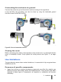
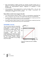
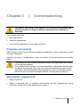
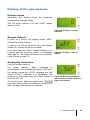
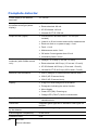
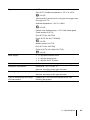
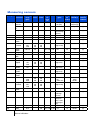
1
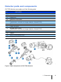
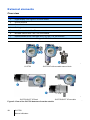
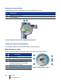
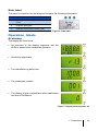
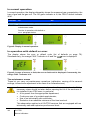
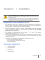
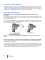
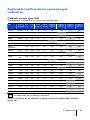
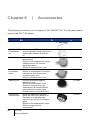
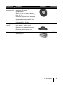
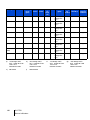
Explosimeter, toxic gas and oxygen detector OLCT60 model Ref : NPO60GB rev A User manual (Ref : xxxxFR rev A) Copyright 2011 by Industrial Scientific – Oldham S.A.S First edition, English version All rights reserved. No reproduction of all or part of this document, in any form, is permitted without the written consent of Industrial Scientific – Oldham S.A.S. All of the information that is provided in this document is accurate to the best of our knowledge. As a result of continuous research and development, the specifications of this product may be changed without prior notice. Industrial Scientific Oldham S.A.S Rue Orfila Z.I. Est – BP 20417 F – 62027 ARRAS Cedex Tel: +33 (0)3 21 60 80 80 Fax: +33 (0) 3 21.60.80.00 2 OLCT60 Manuel utilisateur Contents Chapitre 1 | Presentation ........................................................7 Purpose ......................................................................................................7 Operating principle .....................................................................................8 Detector parts and components .................................................................9 External elements ....................................................................................10 Internal elements......................................................................................12 Labels and pictograms .............................................................................12 Operation labels ......................................................................................13 Chapitre 2 | Installation .........................................................17 Regulations and conditions of use ...........................................................17 Necessary equipment ..............................................................................17 Location of the detector............................................................................18 Detector positioning .................................................................................18 Electrical power supply ............................................................................20 Connector cable .......................................................................................20 Cable connection .....................................................................................22 Use limitations ..........................................................................................25 Transfer curve ..........................................................................................26 Chapitre 3 | Commissioning .................................................27 Purpose of control ....................................................................................27 Necessary equipment ..............................................................................27 Commissioning.........................................................................................28 Stabilization time ......................................................................................28 Display of the gas measure......................................................................29 Zeroing .....................................................................................................30 Adjustment of gas sensitivity....................................................................31 Chapitre 4 | Preventive maintenance ...................................33 Maintenance schedule .............................................................................33 Actions......................................................................................................34 Chapitre 5 | Maintenance ......................................................35 Table des matières 3 Possible errors .........................................................................................35 Replacing sensor block (Explo, O 2 , Tox, XP-IR) ...................................36 Replacing the OLCT IR – integrated version ...........................................37 Replacing the OLCT IR – remote version ................................................37 Initialization of the sensor block ...............................................................38 Zeroing and sensitivity adjustment (calibration).......................................40 Adjusting the optical zero (Ir-0) ................................................................45 Applicable coefficients for explosive gas calibration ................................47 Checking the line current .........................................................................49 Chapitre 6 | Accessoires .......................................................50 Chapitre 7 | Spare parts ........................................................52 Explosionproof sensor block ....................................................................52 Intrinsically safe sensors ..........................................................................54 Chapitre 8 | I EC Statement of compliance ..........................56 Chapitre 9 | Technical specifications ...................................60 Dimensional characteristics .....................................................................60 Complete detector....................................................................................62 Measuring sensors...................................................................................64 Chapitre 10 | Special instructions for use in explosive environments and functional safety ........................................68 General comments...................................................................................68 Metrological performance for the detection of flammable gases .............68 Threaded joints ........................................................................................69 Operating safety .......................................................................................69 Reliability data ..........................................................................................69 Chapitre 11 | Fault and error codes .......................................70 Errors (E xx) .............................................................................................70 Faults (dEF xx) .........................................................................................70 Contents ......................................................................................72 4 OLCT60 Manuel utilisateur Thank you for choosing this OLDHAM instrument. All of the necessary actions have been taken in order to ensure your complete satisfaction with this equipment. It is important that you read this entire manual carefully and thoroughly. Limited liability OLDHAM INDUSTRIAL SCIENTIFIC shall not be held responsible for any damage to the equipment or for any physical injury or death resulting in whole or in part from the inappropriate use, installation, or storage of the equipment, which is the result of not complying with the instructions and warnings, and/or with the standards and regulations in force. OLDHAM INDUSTRIAL SCIENTIFIC does not support or authorize any business, person, or legal entity in assuming responsibility on behalf of OLDHAM INDUSTRIAL SCIENTIFIC, even though they may be involved in the sale of OLDHAM INDUSTRIAL SCIENTIFIC products. INDUSTRIAL SCIENTIFIC OLDHAM shall not be responsible for any damage, direct or indirect, or for damages and interests, direct or indirect, resulting from the sale and use of any of its products UNLESS SUCH PRODUCTS HAVE BEEN DEFINED AND CHOSEN BY OLDHAM INDUSTRIAL SCIENTIFIC FOR THEIR INTENDED USE. Ownership clauses The drawings, specifications, and information herein contain confidential information that is the property of OLDHAM INDUSTRIAL SCIENTIFIC. This information shall not, either in whole or in part, be reproduced, copied, divulged, translated, or used for the manufacture or sale of INDUSTRIAL SCIENTIFIC OLDHAM equipment by physical, electronic, or any other means whatsoever and for any other reason without the prior consent of OLDHAM INDUSTRIAL SCIENTIFIC. Limites de responsabilité 5 Warnings This is not a contractual document. INDUSTRIAL SCIENTIFIC OLDHAM reserves the right to alter the technical features of its equipment without prior notice if required in the best interest of its customers and with the aim of improving performance. READ THESE INSTRUCTIONS CAREFULLY BEFORE THE FIRST USAGE: these instructions should be read by all persons who have or will have responsibility for the use, maintenance, or repair of the instrument. This instrument shall only be deemed to be in conformance with the published performance if used, maintained, and repaired in accordance with the instructions of INDUSTRIAL SCIENTIFIC OLDHAM, its personnel or by personnel authorized by INDUSTRIAL SCIENTIFIC OLDHAM. Warranty 2-year warranty on defective parts and workmanship including return to the factory and unless misuse. The warranty does not cover consumable parts as sensors, filters, etc. Disposal of the equipment European Union (and EEE) only. This symbol indicates that, in conformity with DEEE Directive (2002/96/EC) and according to local regulations, this product may not be discarded together with household waste. It must be disposed of in a collection area that is set aside for this purpose, for example at a site that is officially designated for the recycling of electrical and electronic equipment (EEE) or a point of exchange for authorized products in the event of the acquisition of a new product of the same type as before. 6 OLCT60 Manuel utilisateur Chapter 1 | Presentation Purpose OLCT60 gas detectors are 4-20mA and 3-wire transmitters designed for measuring combustible and toxic gas as well as oxygen. They are available: As anti explosion protection system with explosion proof enclosure and sensor block This version is approved and listed as OLCT60d. As anti explosion protection and inbuilt safety system with explosion-proof enclosure and safety sensor block. This version is available for electrochemical sensors only. This version is approved and listed as OLCT60id. The versions that are presently available are listed on the following table. OLCT60d (1) OLCT60 id (2) Catalytic sensor Electrochemical sensor XPIR Infrared sensor OLCTIR Infrared sensor 1: 2: OLCT60 anti-explosion transmitter with inbuilt explosion-proof detector OLCT60 anti-explosion transmitter with inbuilt intrinsically safe detector. Table 1: Comparative table for gas detectors, OLCT60 series. For detailed sensor features please see page 64 and following ones. The OLCT60 series includes 2 transmitter versions: The OLCT60 version with fixed sensor. By this name one can tell whether the anti explosion transmitter is or is not combined with an inbuilt, intrinsically safe detection unit. The OLCT60D version with movable sensor By this name one can tell whether the anti explosion transmitter is or is not combined with an intrinsically safe, movable sensor. The versions that are presently available are listed on the following table. 1 - Présentation 7 Name Description OLCT60 ADF housing with inbuilt sensor block (ADF or intrinsically safe*). OLCT60D ADF housing with 15 m movable sensor block (ADF or intrinsically safe*). OLCT60 / OLCT IR ADF housing with ADF fixed sensor block type OLCT-IR. OLCT60D / OLCT IR ADF housing with ADF movable sensor block type OLCT-IR. Illustration 044 046 048 050 (*) The intrinsically safe version is distinguished - among other features - by the color of the sensor block that is blue for intrinsically safe versions and raw stainless steed for explosion proof versions. Operating principle The measuring sensor converts the target gas into current. The current value is amplified, corrected temperature wise, linearised, and converted into a 4-20 mA proportional signal to the concentration of the measured gas and then conveyed through connecting cable to a centralized unit (measurement unit or industrial automation system). The measuring sensor changes depending on the type of detector as shown in 2: OLCT60 anti-explosion transmitter with inbuilt intrinsically safe detector. , on page 7. 8 OLCT60 Manuel utilisateur Detector parts and components OLCT60 detectors are made up of the following parts: Id. Description 1. Manufacturer's Label 2. Cover 3. Display unit 4. Electronic circuit board 5. Fixed sensor block (explosimeter, toximeter and oxygen detector, infrared XP-IR). 6. Enclosure 7. Cable inlet gland 8. Movable sensor block (explosimeter, toximeter and oxygen detector, infrared XP-IR) 9. Connection cable for movable sensor block 10. Adapter 11. OLCT IR fixed sensor block 12. OLCT IR movable sensor block 004 Figure 1: Main components of OLCT60 detectors. 1 - Présentation 9 External elements Overview Id. Description 1. Digital display See Figure 3 for more details 2. Ground terminal 3. Cover fixation screw 4. Cable gland 5. Inbuilt sensor block See 7 for more details 6. Movable sensor block See 7 for more details 7. Infrared sensor block, fixed type OLCT-IR. See 7 for more details 8. Infrared sensor block, movable type OLCT-IR. See 7 for more details 012A OLCT60 OLCT60 D with movable sensor block 012B OLCT60/OLCT-IR fixed OLCT60/OLCT-IR movable Figure 2: View of the OLCT60 detectors from the outside. 10 OLCT60 Manuel utilisateur 012 Difference between ADF and SI sensors Although they have different ATEX marking, the intrinsically safe, explosionproof sensors are visually distinguished by the color of the sensor block as following: Explosionproof sensor: Non-painted, stainless steel sensor equipped with sinter metal. Intrinsically safe sensor: Blue painted, stainless steel sensor equipped with sinter metal. Display and LEDs Id. 1. Description Digital display exhibiting the following readings: - gas measure and type alternated with gas unit. If an error occurs, the respective error code is displayed instead of the measure. Error codes are displayed along with the orange LED. Please revert to section Readings on the display, page Erreur ! Signet non défini.. - Maintenance menus after accessing. Please revert to section Menus, page 14. 2. Magnetic contact for menu selection 3. Orange Error LED (detector fault or sensor configuration in progress) 4. Green LED for electric power supply. 5. Magnetic contact for validation. 6. Magnet for magnetic contacts activation (marking 2 and 5). 018 Figure 3: Detailed view of the display and its related peripheries (LED and active zones). 1 - Présentation 11 Internal elements The following internal components can be accessed by the user: Id. Description 1. Electronic circuit board 2. Terminal board 006 Figure 4: Detector internal view, display block taken off. Labels and pictograms The detectors has two identification labels, as shown below: Manufacturer label On the cover: this label features the main characteristics of the detector: Id. 1. Description ATEX marking 2. Type of product 3. Manufacturer's name 4. IECx marking and maximum ATEX certification temperature (excluding metrological performance) 5. Warning 6. 12 EC and Ex certification mark OLCT60 Manuel utilisateur 008 Figure 5: Manufacturer label Side label This label is located on the housing and includes the following information: Id. 1. Description Reference of the detector without sensor (P/N) 2. Disposal pictogram 3. Detector production number (S/N). 010 Figure 6: Side label Operation labels At startup The display will then show: An overview of the display segments and the LEDs to assess their troublefree operation. L_00 Sensitivity adjustment L_02 The manufacturing date code. L_04 The production number. L_06 The display of gas concentration after stabilization and test of the sensor. L_008 Figure 7: Display steps at power up. 1 - Présentation 13 In normal operation In normal operation, the display alternately shows the measured gas concentration, the type of gas and the gas unit. The OK green indicator is lit; the FAULT default indicator is off. Indicator Lit Off OK Detector under voltage. Detector off. FAULT Detector default or detector in maintenance mode. Lack of detector default. See the In operation with default or error paragraph below. L_010A L_010B Figure 8: Display in normal operation. In operation with default or error The display shows the error or default code (list of defaults on page 70). icon is displayed. Simultaneously, the orange FAULT indicator is lit and the L_014A L_014B Figure 9: In case of an error or fault, the error or fault code is displayed. Concurrently, the orange FAULT indicator is lit. The maintenance menus These let you carry out maintenance operations (calibration, zeroing of the sensor's settings, internal zero adjustment in the case of an infrared sensor) Access to maintenance menus is done when the cover is closed. All the necessary steps should be taken before opening the lid of the enclosure if it is installed in an ATEX zone, in particular: A fire permit from the appropriate department; Continuous use of a portable explosimeter; Use of an intrinsically safe multimeter; Reduction to an absolute minimum of the time involved. This observation applies to all OLCT60 versions that are equipped with an intrinsically safe and explosion-proof sensor block. 14 OLCT60 Manuel utilisateur Access The access to the menus is done without opening the cover, with the use of a magnet (pos. 1) that will be positioned on the (pos. 2). 034 Figure 10: The positioning of the magnet on the VALID area allows access to the menu. List of menus An OLCT60 type sensor usually has two menus while OLCT 60 sensors with infrared sensor (XP-IR or OLCT - IR) have three menus. Measurement display (page 29) (page 40) (page 37) L_022_A (page 45) L_022B Figure 11: Menus accessible on an OLCT60 (left) and an OLCT60 equipped with an infrared detection module (right). 1 - Présentation 15 Main functions in the menus CAL: access to the zero setting and sensitivity menu. See page 40. Init: initialization of the setting parameters. This function is only used after the changing of a sensor. See page Erreur ! Signet non défini.. Ir-0: Zero adjustment of the optical part. This function is only used with an XPIR or OLCT IR infrared sensor after the cleaning of the optical parts (lense and mirror on the OLCT IR). See page 45. Use of the menus Their detailed use is the subject of 0. 16 OLCT60 Manuel utilisateur Chapter 2 | Installation It is recommended to read the installation guide for use and maintenance of the detectors for flammable gases and oxygen (EN/IEC 60079-29-2) and toxic gases (EN 45544-4). The installation will be done according to current standards, the classification of the area, in compliance with the current editions of standards EN/IEC 6007914, EN/IEC 61241-14 and other national and/or local regulations. Regulations and conditions of use The installation will be done according to current standards for installation in explosive areas especially regulations IEC/EN 60079-14 and IEC/EN 60079-17 (current editions) or according to other national standards. Generally, temperature conditions, the power supply voltages and power mentioned in this document are relative to explosion safety. This is not the operating temperatures of the detector. The equipment is authorized for use in Zones 1, 2, 21 and 22 for ambient temperatures ranging from -50 °C to + 70 °C. In the case of the OLCT60 D id version, the sensor block can be used in zones 0, 1, 2, 20, 21 and 22 if there is a remote transmitter. The transmitter itself may not be used in Zone 0 or 20. The detector must always be in contact with the ambient air. Thus: - Do not cover the detection module. - Do not use paint on the detection module. - Avoid dust deposits. Necessary equipment Complete detector. Connector cable Fixing tools. Fixing material. 2 - Installation 17 Location of the detector The detector shall be positioned at the ground level, or on the ceiling at the same height as the airflow, or near to the air extraction ducts depending on the density of gas to detect or use. Heavy gases may be detected at the ground level, while light gases will be found at ceiling height. Gas densities are found on page 46. Detector positioning All version of the integrated measuring block excluding OLCTIR The detector will be installed with the detector sensor pointing downwards. For explosive gas detectors only, any tilt of more than 45° from the vertical will lead to an inaccurate measurement. Fixture of the enclosure shall be secured with 2 x M6 screws and the appropriate plugs for the supporting material. A special holder is available for mounting the detector on the ceiling (see section on Accessories). 016 Figure 12: Sensor pointing downwards (left) and maximum tilt angle for an explosimeter (right). All version of the remote measuring block excluding OLCTIR For explosive gas detectors only, any tilt of more than 45° from the vertical will lead to an inaccurate measurement. Fixture of the enclosure shall be secured with 2 x M6 screws and the appropriate plugs for the supporting material. That of the block sensor will be done with at least 2 x M6 screws and the appropriate plugs for the supporting material. A special holder is available for mounting the detector on the ceiling (see section on Accessories). 18 OLCT60 Manuel utilisateur 036 Figure 13: Sensor pointing downwards (left) and maximum tilt angle for an explosimeter (right). OLCTIR version with integrated measuring block only The detector will be installed with the horizontal detector sensor and the arrow on the anti-projection device pointing upwards. Fixture of the enclosure shall be secured with 2 x M6 screws and the appropriate plugs for the supporting material 030 Figure 14: OLCT IR detector MUST be laid horizontally, arrow pointing upwards. 2 - Installation 19 OLCTIR IR version with remote measuring block only The OLCT-IR detector will be installed with the horizontal detector sensor and the arrow on the anti-projection device pointing upwards. 15 m max. 056 Figure 15: OLCT IR must be laid horizontally, arrow pointing upwards. Electrical power supply Type of detector Type of sensor Power supply (Vcc) Explosimeter Catalytic 16 to 32 140 2,24 Explosimeter Infrared (XP-IR) 16 to 32 120 1,92 Explosimeter Infrared (OLCT IR) 16 to 32 550 8,80 Toximeter Electrochemical 16 to 32 80 1,28 Oxygen detector Electrochemical 16 to 32 80 1,28 Semiconductor 16 to 32 140 2,24 Freon Maximum current (mA) Power consumed (W) Connector cable The detector shall be connected to the central unit (measurement and automation unit) by a 3-wire shielded instrumentation cable, armoured if necessary. The choice of cable will be dictated by the particular requirements of the installation, distance, and type of detector (see table below). 20 OLCT60 Manuel utilisateur Central unit Connector cable Detector 022 Figure 16: The cable connecting the detector to the central unit should be chosen with care. Type of detector Type of sensor Upstream line voltage (Vcc) Explosimeter Catalytic Maximum length (km) for cable of crosssection as indicated Maximum load resistance () 0..5mm² 0.9 mm² 1.5 mm² 24 24 24 0,55 1,0 1,7 250 Explosimeter Infrared (XP-IR) 0,65 1,2 2,0 250 Explosimeter Infrared (OLCT IR) 0,13 0,25 0,45 300 Toximeter Electrochemical 1,0 1,8 3,0 250 Oxygen detector Electrochemical 1,0 1,8 3,0 250 Freon Semiconductor 0,55 1,0 1,7 250 Table 2: Table of line lengths. The cable must have a braided screen to reduce the influence of electrical and radiofrequency interference. A cable such as AFNOR M 87-202-01-IT-15-EG-FA (Nexans) may be used. It shall be selected according to the type of detector and in accordance with the table shown hereinabove. Here are some more examples of suitable cables: Non ATEX zone: CNOMO FRN05 VC4V5-F ATEX zone: GEVELYON (U 1000RHC1) ATEX zone: GVCSTV RH (U 1000) ATEX zone: xx-xx-09/15- EG-SF or EG-FA or EG-PF (U 300 compatible with M87202) The maximum permissible length will depend on the cross-section of the cable conductors (see table) and on the minimum admissible supply voltage at the detector terminals. 2 - Installation 21 Cable connection Switch off line power supply On the central unit: 1. Inhibit any installation alarms to avoid unexpected triggering during operation. 2. Switch off the power to the detector. Opening of the detector Remove the 4mm hex screw locking the lid (notch 1) before unscrewing the lid of the detector. 032 Figure 17: Locating the hex screw (4 mm) locking the lid. Cable preparation. The cable shall be taken from the central unit (measurement and automation) to the point of measurement (see Figure 16). The passage, support, and protection of the cable shall be according to best practice . Cable passage It is essential that the instructions provided by the manufacturer of the compression gland are followed and the braided screen is correctly connected. 22 OLCT60 Manuel utilisateur Sensor Washer Shield Armored shield groundin g device Sealing ring Cable Anchoring collar 060 Figure 18: Example of connection of armored and unarmored cable. Sensor Sealing ring Sealing ring Cable Armored Armour earthing device 062 Figure 19: Example of double compression cable gland for armored cable clamp. Cable connection (OLCT60) The connection of the cable between the detector and central unit should be made with the power off. The site must be equipotential. Connect the cable to the detector side before connecting the central unit side. After the wiring has been completed, connect the cable shield to the ground terminal of the central unit. + 24 Vcc 0V Signal 026 Figure 20: Connections for a OLCT60 (d or id version). 2 - Installation 23 Connection of the cable (OLCT60/OLCT IR remote) The connection of the cable between the detector and central unit should be made with the power off. The site must be equipotential. First carry out the connection between the OLCT IR cable (A notch and the detector ( B-notch ), as shown in Figure 21. The maximum distance is 15 meters. The type of cable to use is 02-IP-09-EG-FA or EG-SF or similar; see page 21. Then connect the cable (C notch to the detector before the connection to the central unit as shown in Figure 20. After the wiring has been completed, connect the cable shield to the ground terminal of the central unit. 15 meters maximum 042 Figure 21: Connection for a OLCT60D/OLCT-IR. Ensure the specificity of the numbering of the connector marked «D» compared to the connector marked «E». 24 OLCT60 Manuel utilisateur Connecting the enclosure to ground Connect the enclosure ground terminal to earth according to the regulations. In the OLCT60, this grounding can also be done by using the dedicated ground terminal located inside the housing. 028 Figure 22: Ground connection terminal Closing the cover Before connecting the cable to the terminal on the central unit, it is essential that the cover is completely closed. Firmly tighten the locking screw (see Figure 17, on page 22). Use limitations The gas detector sensors have certain limitations; it is essential to fully recognize these limitations (see 0). Presence of specific components Vapor from silicone or sulphur-containing components can affect the catalytic gas detector sensors and thereby distort the measurements. If the sensors have been exposed to these types of compounds, an inspection or calibration will become necessary. 2 - Installation 25 High concentrations of organic solvents (e.g. alcohols, aromatic solvents, etc.) or exposure to quantities of gas greater than the specified range of measurement can damage the electrochemical sensors. Inspection or calibration is then recommended. In the presence of high concentrations of carbon dioxide (CO2 > 1% vol.), the oxygen-measuring electrochemical sensors can slightly overestimate the concentration of oxygen (0.1 to 0.5% volume). Operation under low oxygen levels If an electrochemical detector sensor is used in an atmosphere comprising less than 1% oxygen for over one hour, the measurement may be an underestimate. If a semiconductor detector sensor is used in an atmosphere comprising less than 10% oxygen, the measurement may be an underestimate. If a semiconductor detector sensor is used in an atmosphere comprising less than 18% oxygen, the measurement may be an underestimate. Transfer curve The curve shown gives the transmitter output current as a function of the gas concentration. If you connect the transmitter to a different unit than the one provided by ISC Oldham, make sure that the transfer curve is fully compatible with the input characteristics of your device to ensure proper interpretation of the information provided by the transmitter. Similarly, the unit should provide sufficient voltage to compensate for any voltage drop in the cable. Current outgoing (mA) Default Default % scale 014 Figure 23: transfer curve for a 4-20 Ma detector. 26 OLCT60 Manuel utilisateur Chapter 3 | Commissioning The actions described in this chapter are restricted to authorized and trained personnel as they are likely to undermine the reliability of detection. This chapter describes: Zero adjustment. Sensitivity adjustment. The eventual adjustment of zero and sensitivity. Purpose of control Upon delivery, each sensor has been tested and calibrated. There is normally no need for a new calibration. However, for safety, it is advisable to carry out checks of zero and sensitivity as shown below. The detector lid shall remain completely closed; the adjustments are carried out through the window. For a explosimetric detector, we recommended to calibrate the detector with the gas to be detected. When the user wishes to calibrate the detector with a gas other than that detected and programmed, refer to the table on page 46 for the use of recommended gas and the corresponding coefficient. Necessary equipment Bottle of pure air. Bottle of standard gas, of suitable concentration for the measurement range (between 30 and 70% of the measurement range). 3 – Mise en service 27 Commissioning Prior checks Check the following points: Wiring completed. Detector housing grounded. Connection made between the connector cable braided screen and central unit ground. Integrity of the mechanical mounting (fixings, cable gland, and cover) ensured. Powering up detector 1. Inhibit any installation alarms to avoid unexpected triggering during operation. 2. Connect power to the detector line in accordance with the manufacturer's instructions. Stabilization time Filter mounting, it is essential to allow the detector temperature to stabilize. In addition, after turning the power on, certain sensors require a further pre-heating time. Any adjustment before the time indicated will result in an incorrect measurement, which may in turn compromise the safety of the goods and personnel. The total waiting time is summarized below: Explosimeter: 2 hours. Oxygen detector: 1 hour. Electrochemical detector: 1 hour, excluding - NO (nitrogen monoxide): 12 hours. - HCl (hydrochloric acid): 24 hours. - ETO (ethylene oxide): 24-36 hours. Semiconductor sensor: 4 hours. Infra-red detector (XP-IR): 2 hours. Infra-red detector (OLCT IR): 2 hours. 28 OLCT60 Manuel utilisateur Display of the gas measure Normal mode Alternately, the display shows the measured concentration and type of gas. The OK green indicator is lit; the FAULT default indicator is off. L_00 Figure 24: Display in normal operation. Sensor default In case of a failure, the display shows «dEF» followed by a fault number. In case of an internal electronic error, the display shows «E» followed by an error number. In the two cases, the FAULT (default) indicator is lit. Proceed with the corrective action in compliance with page 35. The display shows the error or default code is found on page 70. L_00 Figure 25: Display in case of default. Ambiguity resolution (only the catalytic version) For safety reasons, when measuring a concentration of a flammable gas above 100% LEL, the display shows the «SUP» message and the default «FAULT » indicator is lit. Meanwhile, the measure is inactivated and the output signal is frozen at 23.2 mA. To exit this mode, add the magnet to the area after having verified the absence of the ATEX with a portable explosimeter for example. L_00 Figure 26: Readings displayed when the explosimeter detects a high concentration. 3 – Mise en service 29 Zeroing Proceed as follows: 024 Figure 27: Zeroing. 1. Inhibit alarm signals on the central unit. 2. Place the calibration shroud onto the detector head (Figure 27, rep. B). 3. Branch the calibrator shroud to the pure air bottle (Pos. E) using a flexible hose (Pos. C). 4. Open the valve on the pure air bottle (flow rate 30 to 60 liters/hr or 60 to 120 liters/hr in the case of OLCT IR versions) (rep. D). 5. After the measurement has stabilized (approx. 2 minutes), read the display of the central measuring unit (rep. A). 6. If the expected value does not comply, proceed with the calibration (paragraph Zeroing and sensitivity, on page 40). 7. See paragraph Adjustment of gas sensitivity, on the next page. 30 OLCT60 Manuel utilisateur Adjustment of gas sensitivity For safety reasons, this procedures must come after the zeroing (page 29). Proceed as follows: 038 Figure 28: Sensitivity adjustment. 1. Once zeroing is completed, connect the calibration shroud to the standard gas bottle (Pos. E) using a flexible hose (Pos. C). 2. Open the valve on the standard gas bottle (flow rate 30 to 60 liters/hr or 60 to 120 liters/hr in the case of OLCT IR versions) (rep. D). 3. After the measurement has stabilized (approx. 2 minutes), read the display of the central measuring unit. 4. If the expected value does not comply, proceed with the calibration (paragraph Zeroing and sensitivity, on page 40). 5. Close the valve (rep. D) of the bottle and remove the calibration shroud (rep. B). Walt for the measured signal to return to zero and reset the alarm signals on the central unit. The zeroing and gas sensitivity procedure is completed. The detector can be used. 3 – Mise en service 31 32 OLCT60 Manuel utilisateur Chapter 4 | maintenance Preventive Periodic checks enable the equipment and installation to remain in conformity and ensure reliable detection. This chapter describes what preventative action should be taken and at what intervals. Inspection and maintenance are carried out in accordance with standards in force EN60079-17 or IEC 60079-17, with whatever editions are in force or with other national standards. Maintenance schedule Gas detectors are safety devices. OLDHAM recommends the regular testing of fixed gas detection installations. This type of test consists of injecting standard gas into the detector at a sufficient concentration to activate the pre-set alarms. . It is to be understood that this test is in no way a replacement for a detector calibration. The frequency of gas tests depends on the industrial application where the detector is in use. Frequent inspections should be made in the months following the commissioning of the installation, and should then become more widely spaced provided that no significant deviation is observed. The interval between tests should not exceed 3 months. If a detector should fail to react in contact with the gas, calibration is essential. The frequency of calibrations shall be adjusted according to the results of the tests (humidity, temperature, dust, etc.); however, no longer interval than one year should occur. The general manager should put safety procedures in place on-site. INDUSTRIAL SCIENTIFIC cannot be held responsible for their enforcement. To attain a SIL capability level according to European standard EN 50402, Requirements relating to the safety operation of fixed gas detection systems, the maintenance interval for explosive gas detectors must be no more than 6 months. To obtain the SIL capability 2 level, the maintenance interval must be no more than 3 months. 4 – Entretien périodique 33 Actions OLCT60 Periodic maintenance comprises the following actions: Removal of dust from the sensor’s protective housing, using only a dry cloth. No water or solvents should be used. Severely dusty heads or sensors should be replaced immediately. For use in dusty explosive atmospheres, the user should undertake full and regular cleaning to avoid the build-up of dust. The maximum permissible thickness of a dust layer must be less than 5 mm. Replacement of screws: if the screws on the fire-proof part “d” of the body need to be replaced, screws of equal quality or better than A4.70 should be used. Zero inspection with pure air; see page 29. Comply with the actions described in this paragraph in case of deviation. Gas sensitivity check; see page 30. Comply with the actions described in this paragraph in case of deviation. OLCT60/ OLCT IR Refer to the specific OLCT IR manual. 34 OLCT60 Manuel utilisateur Chapter 5 | Maintenance Maintenance primarily comprises changing any sensors that no longer meet their initial metrological characteristics. Since they are liable to affect detection reliability, the tasks described in this chapter are reserved for authorized trained personnel only. Inspection and maintenance shall be carried out in accordance with standards EN60079-17 or IEC 60079-17, with whatever editions are in force or with other national standards. Possible errors The table below summarizes the various possible detector errors. Observed default Possible cause Action Line current 0 mA Connector cable Check cable Power supply Check voltage to the detector terminals - Electronic card Change sensor - Sensor Change sensor 49 Line resistance too high Check cable 0 mA < Line current < 1mA (page ) 49 - Power supply Check voltage to the detector terminals - Standard gas not consistent Check the contents of the standard gas Zero setting not possible Sensor Change sensor Electronic card Change sensor Sensitivity adjustment not possible Sensor Change sensor Electronic card Change sensor «SUP» display Ambiguity resolution activated Inhibit the ambiguity resolution with the magnet. 29 Check the sensitivity 42 5 - Maintenance 49 49 35 Replacing sensor block (Explo, O 2 , Tox, XP-IR) This paragraph is not applied to OLCT IR. Refer to the two paragraphs Replacing the OLCT IR on the next page. The sensor block or detection module encloses the actual detector sensor and the corresponding electronics. A sensor block can only be associated with a defined detector; so an oxygen detection module will not be installed in the place of a explosimetric block. Frequency of replacement The sensor block needs to be replaced every time when zeroing, performing gas calibration or preventive maintenance are no longer possible. Exchanging of the sensor Step 1. Action Prepare the following elements: New sensor block. 4 mm Allen wrench. Calibration set (bottle, shroud, etc.) 36 2. Inhibit alarm signals on the central unit. 3. Turn the OLCT60 off. 4. Loosen the locking screw in the sensor head and rotate the sensor head 30 degrees counterclockwise. 5. Unplug the connector and remove the defective sensor head. 6. Replace the worn out detector head with an identical new one. 7. Reassemble in reverse order and tighten the locking screw. 8. Restore power by OLCT60 to the central unit. 9. Install the OLCT60 as explained in detail in the Initialization of the sensor block pagraph on page 37. OLCT60 Manuel utilisateur Replacing the OLCT IR – integrated version Contact the manufacturer or distributor. Replacing the OLCT IR – remote version Exchanging the detector Step 1. Action Prepare the following elements: New OLCT IR detector. 4 mm Allen wrench. Calibration set (bottle, shroud, etc.) 2. Inhibit alarm signals on the central unit. 3. Turn the OLCT60 off. 4. Open the defective OLCT-IR connection terminal and disconnect it. 5. Dismount the defective OLCT-IR and put the new one in. 6. Carry out the connections. Refer to the Connection of the cable (OLCT60/OLCT IR remote version) paragraph on page 23. 7. Reassemble in reverse. 8. Restore power by OLCT60 to the central unit. 9. Install the OLCT60 as explained in detail in the Initialization of the sensor block paragraph on page 37. 5 - Maintenance 37 Initialization of the sensor block Selection of the initializing menu (Init) Illustration Step Action 1a. After the startup phase, the screen will shows the gas content (it may be wrong at this point). Position the magnet on the for 3 seconds. 1b. Until the L_020A icon is displayed... _L020B ...present the magnet 3 consecutive times on the in the 3 seconds. L_020B 1c. The calibration menu (CAL) is displayed. 1d. Present the magnet on the 1e. The initialization menu (Init) is displayed. L_020c . L_Init Initialization of the sensor block This procedure performs zeroing of the electrical parameters of the measuring detector. Illustration Step Action 2a. The Init screen is displayed, present the magnet once on . L_020B 2b. The display indicates « CnF » (Confirmation). 2c. Position the magnet on the L_044 38 OLCT60 Manuel utilisateur . 2d. The display indicates « nOn » (No). 2e. Position the magnet once on the change No to Yes. 2f. Position the magnet once on the to validate the choice. The procedure is then ended and the detector automatically resets. 2g. Wait 4 seconds during the display of the startup page. 2h. The version number of the software is displayed. 2i. The manufacturing date code is displayed. 2j. The serial number is displayed. 2k. Display count-down starts. 2l. When count-down is over, the measuring page is displayed on screen. L_048 to L_046 L_00 L_02 L_04 L_06 L_059 The sensor is operational. L_020A 2m. Subsequently check the gas operation as explained on pages 29 and 30. 5 - Maintenance 39 Zeroing and sensitivity adjustment (calibration) This paragraph will be followed in measuring or control of the zero (page 29) and/or the sensitivity (page 30) to show deviation from the expected values. For safety reasons, it is important to adjust zeroing and gas sensitivity. If you purposely or automatically exit the application, the previous values will be maintained. The sensor leaves the maintenance mode and returns to the measuring mode after 10 minutes of inactivity on the . or For infrared sensor versions This paragraph will be used for the XP-IR or OLCT IR sensor. This menu is not available on other types of sensors. In this case, the use of a XP-IR or OLCT-IR type infrared detection module it is imperative to zero the optics before proceeding as indicated in the Optical zeroing on page 45. Passage in calibration mode Illustration Step Action 1a. Position the magnet on the seconds. 1b. Until the for 3 L_020A icon is displayed... _L020B ...present the magnet 3 consecutive times on the in the 3 seconds. L_020B 1c. The calibration menu (CAL) is displayed. L_020c 40 OLCT60 Manuel utilisateur Zeroing Step 2a. Illustration Action The calibration menu (CAL) is displayed. L_020C Position the magnet once on . 2b. The display now shows a zero indicating the starting of the zero-setting phase. 2c. Position the magnet once on the 2d. The display indicates the actual zero value (potential offset value). 2e. Place the injection cap and inject pure air from the bottle (flow at 30 to 60 liters/hr). L_024 . L_026 Wait approximately 2 minutes for the stabilization of the measure. The zero of a CO2 sensor block must be tested with recycled bottled air or, even better, with nitrogen. Never consider ambient air as a zero value. 2f. The display eventually indicates a value that is different than zero. Position the magnet once on the The zero adjustment is validated. 2g. . L_028 «GE» (Standard gas) is displayed to indicate that the system has switch over to the sensitivity adjustment phase. L_030 5 - Maintenance 41 Adjustment of gas sensitivity Accessing the sensitivity adjustment menu Step 3a Illustration Action «GE» (Standard gas) is displayed to indicate that the system has switched over to the sensitivity adjustment phase. L_030 Establishing the concentration of standard gas Step Illustration Action 4a Position the magnet once on the . 4b. The displayed value corresponds to the default standard gas value, that is 50 in this case. The hundredths digit flashes. 4c. Adjust the value of the hundredth figure by setting the magnet each time on . Each time you activate the magnet, you increase the second digit after decimal point. 4d. Adjust the value of the hundredths by setting the magnet once on . 4e. Adjusting the first digit after decimal point The tenths digit flashes. Repeat the same procedure as for the hundredths. 4f. L_032 Adjusting the second digit after decimal point L_032 L_034 Adjusting the number of units The unit digit flashes. Repeat the same procedure as for the hundredths. L_036 4g Validate the digit of the units by setting the magnet once on . 4h. End of the setting of the standard gas value. 42 OLCT60 Manuel utilisateur Injecting standard gas Step Illustration Action 5a. The display indicates «S» (Sensitivity). 5b. Place the calibration shroud on the detector head and open the cock of the standard gas bottle (flow at 30 to 60 l/hr). 5c. Position the magnet once on the 5d. The displayed value keeps changing until it stabilizes. Wait approximately 2 minutes for the stabilization of the measure. 5e. As soon as the instrument stabilizes at a value, set the magnet on once to exit the sensitivity adjustment function. Now go the next step as described on the following page. L_038 . L_040 L_042 Validating your calibration Step Illustration Action 6a. The display indicates «CnF» (Confirmation). 6b. Position the magnet once on the 6c. The display indicates «nOn» (No). 6d. To validate and confirm your calibration values set the magnet once on to change No into Yes and then on to confirm. L_044 . L_048 Continue as under paragraph End of zero-poin adjustment and calibration. 6e Otherwise place the magnet once on L_046 . When you do so, the detector will return to the measuring mode after 1 minute countdown without applying any of the previous adjustments. L_048 5 - Maintenance 43 End of the zero-setting and calibration procedure Step 7a Action The display will show for instance «59» and start counting these seconds down before switching the detector back on. Please note: This value will depend on the type of sensor. 7b. Close the cock of the standard gas bottle and remove the calibration shroud. 7c. As soon as the countdown is over, the gas ambient concentration must be shown on the display. The detector is now active. Restore the alarm signals on the central unit. 7d. L_059 L_052 If the display shows «dEF» (Default) followed by the fault number, it means that the detector is not active. Check the fault code number (page 70) and implement the recommended remedies. See page 35. 44 Illustration OLCT60 Manuel utilisateur L_054 Adjusting the optical zero (Ir-0) (as in the case of XP-IR and OLCT-IR versions) This menu strictly applies for detectors types XP-IR and OLCT IR prior to calibration of the zero-point and the sensitivity or after cleaning of the optical parts (see page 40). Cleaning of the optical parts is described in the manual of the OLCT-IR. Selecting the menu Illustration Step Action 1a. Position the magnet on the seconds. 1b. Until the for 3 L_020A icon is displayed... _L020B ...present the magnet 3 consecutive times on the in the 3 seconds. L_020B 1c. The calibration menu (CAL) is displayed. 1d. Place the magnet twice on 1e. The calibration menu (Ir-0) is displayed. 1f. Inject pure air for 2 minutes and then just place the magnet on . L_020c . L_IR0 1g. The display indicates « CnF » (Confirmation). 1h. Position the magnet once on the _L020B L_044 . 5 - Maintenance 45 1i. The display indicates « nOn » (No). 1j. Position the magnet once on the to change No to Yes and adjust the optical zero point. L_048 Position the magnet once on the to validate the choice. L_046 Please continue as in paragraph Changing over to calibration mode, page 40. 1k. Position the magnet on to confirm No and exit the calibration function. L_048 46 OLCT60 Manuel utilisateur Applicable coefficients for explosive gas calibration Catalytic sensor type VQ1 The applicable coefficients are shown in the following table. Gas Gross formula LEL LSE (%) (%) Acetone C3H6O 2,15 13,00 Acetylene C2H2 1,50 Ammonia NH3 15,00 Butane C4H10 1,50 Ethane C2H6 Ethanol Petrol Super SP95 Ethylene Flash point(°C) Vapour CoefficientCalibration of density Coefficient- Coefficient- Coefficient- methane gas CH4 methane gas CH4 methane gas CH4 methane gas CH4 Calibration of Calibration of Calibration of -18 2,1 1,65 1,20 0,90 0,80 100 -18 0,9 2,35 1,75 1,25 1,15 30,20 < -100 0,6 0,90 0,65 0,50 0,45 8,50 -60 2,0 1,90 1,50 1,00 0,90 3,00 15,50 135 1,0 1,50 1,10 0,80 0,75 C2H6O 3,30 19,00 13 1,6 2,15 1,70 1,30 1,00 / 1,10 ~6,0 21 3 to 4 1,80 1,35 1,00 0,90 C2H4 2,70 34,00 - 135 1,0 1,65 1,20 0,90 0,80 L.P.G. Prop+But 1,65 ~9,0 < -50 1,9 1,65 1,20 0,90 0,80 Gas oil Rocket fuel 0,60 ~6,0 55 >4 3,20 2,60 1,70 1,55 Natural gas CH4 5,00 15,00 -188 0,6 1,05 0,75 0,60 0,55 Heptane C7H16 1,10 6,70 -4 3,5 2,20 1,80 1,20 1,05 Hexane C6H14 1,20 7,40 -23 3,0 2,10 1,70 1,15 1,05 Hydrogen H2 4,00 75,60 - 0,069 1,25 1,00 0,70 0,60 Methane CH4 5,00 15,00 -188 0,55 1,00 0,75 0,55 0,50 Nonane C9H20 0,70% 5,60 31 4,4 4,00 3,20 2,65 2,10 Octane C8H18 1,00 6,00 12 3,9 2,70 2,00 1,45 1,30 Pentane C5H12 1,40 8,00 -49 2,5 2,10 1,70 1,15 1,00 Propane C3H8 2,00 9,5 -104 1,6 1,55 1,10 0,85 0,75 Propylene C3H6 2,00 11,70 -107,8 1,5 1,65 1,20 0,90 0,80 Styrene C8H8 1.1 8,00 31 3.6 6,30 5,30 3,50 3,00 Toluene C7H8 1,20 7 5 3,1 4,00 2,95 2,15 1,90 Xylene C8H10 1,00 7,60 25 3,7 4,00 2,90 2,15 1,90 : recommended gas for detector calibration Table 3: Coefficients for the calibration of catalytic detectors equipped with a standard sensor VQ1 5 - Maintenance 47 Anti-poison sensor type 4F The reference coefficients are: Raw Formula gas LEL LEL LSE % Vapour density CH Coefficient 4 Acetone C3H6O 2,15 13,0 2,1 2,24 Acetylene C2H2 1,5 100 0,9 1,22 2Butanone C4H8O 1,8 11,5 2,5 2,46 Ethylene C2H4 2,7 34,0 0,98 1,47 Natural gas CH 4 5,0 15,0 0,55 1,05 H Coefficient 2 Butane Coefficient 1,1 1,1 1,2 : recommended gas for detector calibration Table 4: Coefficients for the calibration of catalytic detectors equipped with an anti-poison sensor 4F. Example (first line of the table) Calibration of an «acetone» detector with standard gas at 1% butane concentration. Value to be entered when defining standard gas («GE», step 4b, page 42): 1% (injected butane) x 100 x 0.95 (butane/acetone coefficient) = 63 % LEL 1.5 % (LEL butane) Please note: LEL values vary according to the source Coefficients are accurate to ± 15 %. For other gases/vapors consult our technical service. . 48 OLCT60 Manuel utilisateur Checking the line current + 24 VDC 0V Signal 040 Figure 29: Checking the current generator of the detector. Proceed as follows: 1. Checking the detector for proper power supply (+24V between terminal 2 and 3). 2. Switching the multimeter over to current measurement (0.20 or 0.40 mA scale). 3. Make sure to first inhibit the collection system in order to avoid any interference. Disconnect the signal wire (terminal 1, Pos. B) by branching the detector to acquisition system. Branch the «COM» terminal to the multimeter (Pos. D) to terminal 2 (0 V) of the detector (Pos. A). 4. Branch «mA» terminal to the multimeter (Pos. D) to terminal 1 (signal) of the detector (Pos. A). 5. The current must be 4 mA (Pos. C) when pure air is injected onto the sensor and 20 mA at standard gas concentrations of 100% of the reference measuring scale. 6. At end of all checks and controls, branch the signal wire on terminal 1 (Pos. B) with the acquisition system of the detector. 5 - Maintenance 49 Chapter 6 | Accessories The following accessories do not apply for OLCT60/OLCT-IR. For the latter please revert to the OLCT-IR manual. Accessories Utilization Set of tools Set of maintenance tools 6147870 OLCT60/OLCT IR calibration set Please read OLCT IR manual The shroud is difference and the gas flow is adjustable between 60 and 120 l/h. makes standard gas filling into the sensor easier. Effects on the measurement: similar measurement as for a natural distribution pattern. Effects on response time: none. 6331141 Gas inlet pipe Gas recirculation head Allows bypass measuring. Effects on measurement: no effect if calibration is done at the same conditions (pipe, flow). Effects on response time: none. Splash-guard Protects the detector against splashing liquids. Effects on measurement: none. Effects on response time: the response time at natural diffusion may increase for certain gases. Please consult our technical office. Remote gas injection head 50 Allows the detection of ambient gases and concurrent detection of the presence of standard gas injection hose. Strictly for explosive gases. Effects on the measurement: none. Effects on response time: disregardable. OLCT60 Manuel utilisateur Illustration Illustration 204 6327910 200 6792844 202 6327911 214 Accessories Utilization Mobile PTFE protection filter Protects the gas inlet against splashing and powder contamination. Effects on the measurement: no effect, but can be used to detect O 3 , HCL, HF, CL 2 . Effects on response time: increased response time (please ask our technical office for high-density gas > 3 and low concentrations < 10 ppm). Ceiling gas collector Illustration Illustration 6335975 216 Allows the sensor to detect gas more quickly. (ceiling mount) 6323620 Effects on the measurement: none. Effects on response time: may increase by 10% Magnet Used for menu selection through the detector glass. 6155651 218 6 - Accessoires 51 Chapter 7 | Spare parts Spare parts list for different detectors Spare parts must be original INDUSTRIAL SCIENTIFIC parts. Use of non-original spare parts may impair safety of the instrument. Explosionproof sensor block Illustration Description 6 313 685 OLCT60 0-100% LEL sensor block type VQ1 6 313 872 OLCT60 0-100% LEL butadiene/acetylene sensor block type VQ1 6 313 974 OLCT60 Anti-poison 0-100% LEL sensor block type 4F 6 313 687 OLCT60 0-100% vol CH4 sensor block 6 313 986 Sensor block OLCT60, 0-100% vol H2 or SF6 6 314 060 Infrared sensor block 0-100% LEL CH4 (5% vol) for OLCT60 XP IR 6 314 093 Infrared sensor block 0-100% LEL CH4 (4.4% vol) for OLCT60 XP IR 6 314 094 Infrared sensor block 0-100% LEL C3H8 (propane) for OLCT60 XP IR 6 314 095 Infrared sensor block 0-100% LEL C4H10 (butane) for OLCT60 XP IR 6 314 096 Infrared sensor block 0-100% LEL Isobutane for OLCT60 XP IR 6 314 098 Infrared sensor block 0-100% LEL GPL (5% vol) for OLCT60 XP IR 6 314 099 Infrared sensor block 0-100%vol CH4 for OLCT60 XP IR 6 314 100 Infrared sensor block 0-5% vol. CO2 for OLCT60 XP IR 6 314 101 Infrared sensor block 0-10% vol. CO2 for OLCT60 XP IR 6 313 710 Sensor block OLCT60 02 0 – 30% vol 6 313 688 Cathalytic sensor block NH3 0-5000 ppm for OLCT60 6 313 707 Sensor block OLCT60 NH3 0-100 ppm 6 313 708 Sensor block OLCT60 NH3 0-1000 ppm 6 313 894 Sensor block OLCT60 NH3 0-5000 ppm 52 OLCT60 Manuel utilisateur Illustration Description 6 313 690 Sensor block OLCT60 CO 0-100 ppm 6 313 691 Sensor block OLCT60 CO 0-300 ppm 6 313 692 Sensor block OLCT60 CO 0-1000 ppm 6 313 693 H2-compensated sensor block OLCT60 CO 0-1000 ppm 6 313 695 Sensor block OLCT60 H2S 0-30 ppm 6 313 965 Sensor block OLCT60 H2S 0-30 ppm, no HC-interference 6 313 696 Sensor block OLCT60 H2S 0-100 ppm 6 313 697 Sensor block OLCT60 H2S 0-1000 ppm 6 313 698 Sensor block OLCT60 NH3 0-100 ppm 6 313 699 Sensor block OLCT60 NH3 0-300 ppm 6 313 700 Sensor block OLCT60 NH3 0-1000 ppm 6 313 706 Sensor block OLCT60 H2 0-2000 ppm 6 313 772 Sensor block ADF OLCT60 methylene – methylene chloride 6 313 773 Sensor block ADF OLCT60 R12 6 313 774 Sensor block ADF OLCT60 R134A 6 313 775 Sensor block ADF OLCT60 MOS 7 – Pièces de rechange 53 Intrinsically safe sensors Illustration Description 6 313 748 Sensor block OLCT60 SI 02 0 – 30% vol 6 313 728 Sensor block OLCT60 SI NH3 0-100 ppm 6 313 729 Sensor block OLCT60 SI NH3 0-1000 ppm 6 313 895 Sensor block OLCT60 SI NH3 0-5000 ppm 6 313 694 H2-compensated sensor block OLCT60 SI CO 0-1000 ppm 6 313 711 Sensor block OLCT60 SI CO 0-100 ppm 6 313 712 Sensor block OLCT60 SI CO 0-300 ppm 6 313 713 Sensor block OLCT60 SI CO 0-1000 ppm 6 313 716 Sensor block OLCT60 SI H2S 0-30 ppm 6 313 717 Sensor block OLCT60 SI H2S 0-100 ppm 6 313 718 Sensor block OLCT60 SI H2S 0-1000 ppm 6 313 719 Sensor block OLCT60 SI NO 0-100 ppm 6 313 720 Sensor block OLCT60 SI NO 0-300 ppm 6 313 721 Sensor block OLCT60 SI NO 0-1000 ppm 6 313 722 Sensor block OLCT60 SI NO2 0-10 ppm 6 313 723 Sensor block OLCT60 SI NO2 0-30 ppm 6 313 727 Sensor block OLCT60 SI H2 0-2000 ppm 6 313 730 Sensor block OLCT60 SI HCI 0-30 ppm 6 313 731 Sensor block OLCT60 SI HCI 0-100 ppm 6 313 724 Sensor block OLCT60 SI SO2 0-10 ppm 6 313 725 Sensor block OLCT60 SI SO2 0-30 ppm 6 313 726 Sensor block OLCT60 SI SO2 0-100 ppm 6 313 734 Sensor block OLCT60 SI CI2 0-10 ppm 6 313 746 Sensor block OLCT60 SI ETO 0-50 ppm 6 313 732 Sensor block OLCT60 SI HCN 0-10 ppm 6 313 733 Sensor block OLCT60 SI HCN 0-30 ppm 6 313 736 Sensor block OLCT60 SI COCI2 0-1 ppm 6 313 740 Sensor block OLCT60 SI CIO2 0-3 ppm 6 313 735 Sensor block OLCT60 SI O3 0-1 ppm 54 OLCT60 Manuel utilisateur Illustration Description 6 313 737 Sensor block OLCT60 SI PH3 0-1 ppm 6 313 739 Sensor block OLCT60 SI HF 0-10 ppm 6 313 738 Sensor block OLCT60 SI ASH3 0-1 ppm 6 313 747 Sensor block OLCT60 SI SiH4 0-50 ppm 7 – Pièces de rechange 55 Chapter 8 | I EC Statement of compliance The page below reproduces the EC statement of compliance for the detector series OLCT60. 56 OLCT60 Manuel utilisateur 8 – Déclaration de conformité CE 57 58 OLCT60 Manuel utilisateur 8 – Déclaration de conformité CE 59 Chapter 9 | Technical specifications Dimensional characteristics 064 Figure 30: Dimensional characteristics of OLCT60 detectors with fixed and mobile sensor. 60 OLCT60 Manuel utilisateur 066 Figure 31: Dimensional characteristics of OLCT 60/OLDT-IR detectors with fixed and mobile sensor. 9 – Spécifications 61 Complete detector Power supply to the detector terminals: 15 - 30 Vcc. Average consumption based on the sensor block type (active display): Catalytic: 140 mA. Electrochemical: 80 mA. XP-IR infrared: 120 mA. Infrared OLCT IR: 550 mA. Output current (signal) : Current source encoded from 0 - 23 mA (non isolated) Linear 4 to 20 mA current reserved for measurement Electronic fault or no power supply : 0 mA. Fault: <1 mA. Maintenance mode: 2 mA. Off-scale: Current greater than 23 mA. Uncertainty factor: 20 mA. Maximum resistance per cable conductor (with Oldham control unit) : Catalytic: 32 loop (1 km and 1.5 mm2) Electrochemical: 48 loop (1.5 km and 1.5 mm2) XP-IR infrared: 48 loop (1.5 km and 1.5 mm2) infrared OLCT IR: 8 loop (250 m and 1.5 mm2) Maximum load resistance 250 (catalytic or electrochemical sensor block). 250 (XP IR sensor block). 250 (XP IR sensor block). Display : 4 digit LCD with background illumination. Pictograms indicating the active function. Menu display Green LED (OK): Powering up. Orange LED (FAULT): fault or maintenance. Type of cable: 3 active wires screened between detector and centralized unit. Cable inlet: Integrated gland type M25 is standard. Other types on request. Maximum cable diameter handled 2 -12 mm for integrated glands. by the detector : Electromagnetic compatibility: to EN 50270. Protection class IP66. 62 OLCT60 Manuel utilisateur Explosive environments: (ADF version) Ex d IIC T6. Ambient temperature: –20 °C à +60°C. II 2 GD. Version with SI sensor block, toxic gas and oxygen only Ex d [ia] ia IIC T4 Ambient temperature: –20 °C à +60°C. II 2 GD. Please note: Ambient temp. = 55°C with inbuilt gland. Fixed version OLCT IR Ex d IIC T6 (for OLCT60) Ex de IIC T4 (for OLCT IR M25) II 2 GD. Mobile version OLCT IR Ex d IIC T6 (for OLCT60) Ex de ia IIC T4 (for mobile OLCT IR) II 2 GD. Mass weight: 1.6 kg without sensor block. 2.1 kg with sensor block. 4,1 kg with OLCT-IR block. Materials: Operation temperature: Painted aluminum with epoxy polyester coating. Electronics: -25 °C à +55 °C. Sensors: according to the type of sensor. Stocking temperature: Electronics: -25 °C à +60 °C. Sensors: according to the type of sensor. Type of detected gas and range of measurement: Depending on the connected sensor block. See following paragraphs. 9 – Spécifications 63 Measuring sensors Type of gas Measuring range (ppm) ADF sensor SI Temperat % HR sensor ure range (°C) Precision (ppm) Explosive gas Infrared OLCT IR 0-100% LEL -25 to +55 0 – 99 +/- 5% (CH4) +/- 3% (HC) >60 9/15 (CH4) (e) 7/8 (CH4) (f) (a) Infrared XP IR 0-100% LEL -25 to +55 0 – 95 +/- 5% 48 11/30 (CH4) (a) Catalytic 0-100% LEL -25 to +55 0-95 40 6/15 (CH4) (b) +/-1 % LEL (from 0 through 70% LEL) Average Tps pos. T50/T90 (s) life (months) Storage time and conditions AsH3 Arsine 1,00 -20 to +40 20 – 90 +/- 0,05 18 30/120 (a) Cl2 Chlorine 10,0 -20 to +40 10 – 90 +/- 0,4 24 10/60 (a) ClO2 Chlorine dioxide 3,00 -20 to +40 10 – 90 +/- 0,3 24 20/120 (a) CO Carbon monoxide 100 300 1000 -20 to +50 15 – 90 +/- 3 (range: 0-100) 40 15/40 (a) CO2 Carbon dioxide 0-5% vol. -25 to +55 0 – 95 +/- 3% 48 11/30 (a) COCl2 Phosgene 1,00 -20 to +40 15 – 90 +/- 0,05 12 60/180 © ETO Ethylene oxide 30,0 -20 to +50 15 – 90 +/- 1,0 36 50/240 (a) H2 Hydrogen 2000 -20 to +50 15 – 90 +/- 5% 24 30/50 (a) H2S Hydrogen sulphide 30,0 100 1000 -25 to +50 15 – 90 +/- 1.5 (range: 0-30) 36 15/30 (a) HCl Hydrogen chloride 30,0 100 -20 to +40 15-95 +/- 0.4 (range: 0-30) 24 30/150 (a) HCN Hydrogen cyanide 30,0 -25 to +40 15-95 +/- 0.3 (range: 0-10) 18 30/120 © HF Hydrogen fluoride 10,0 -10 to +30 20 – 80 +/- 5% 12 40/90 © NH3 Ammonia 100 1000 5000 -20 to +40 15 – 90 +/- 5 +/- 20 +/- 150 or 10% 24 25/70 20/60 60/180 (a) NO Nitrogen monoxide 100 300 1000 -20 to +50 15 – 90 +/- 2 (range: 0-100) 36 10/30 (a) NO2 Nitrogen dioxide 30,0 -20 to +50 15-90 +/-0,8 24 30/60 (a) O2 Oxygen 0-30% vol. -20 to +50 15 – 90 0,4% Vol (15 through 22% O2) 28 6/15 (a) O3 Ozone 1,00 0 to +40 10 – 90 +/- 0,03 (0 through 0,2 ppm) +/- 0,05 (0,2 through 1 ppm) 18 40/120 © PH3 Phosphine 1,00 -20 to +40 20 – 90 +/- 0,05 18 30/120 (a) SiH4 Silane 50,0 -20 to +40 20 – 95 +/- 1,0 18 25/120 (a) 64 OLCT60 Manuel utilisateur Type of gas Measuring range (ppm) ADF sensor SO2 Sulphur dioxide 10,0 30,0 100 CH3Cl Chloromethane 500 CH3Cl Dichloromethane 500 Freon R12 SI Temperat % HR Precision sensor (ppm) ure range (°C) -20 to +50 15 – 90 +/- 0.7 (range: 0-10) Average Tps pos. T50/T90 (s) life (months) Storage time and conditions 36 15/45 (a) -20 to +55 20 – 95 +/- 15% (20 through 70% PE) 40 25/90 (d) -20 to +55 20 – 95 +/- 15% (20 through 70% PE) 40 25/90 (d) 1 % vol. -20 to +55 20 – 95 +/- 15% (20 through 70% PE) 40 25/90 (d) Freon R22 2000 -20 to +55 20 – 95 +/- 15% (20 through 70% PE) 40 25/90 (d) Freon R123 2000 -20 to +55 20 – 95 +/- 15% (20 through 70% PE) 40 25/90 (d) FX56 2000 -20 to +55 20 – 95 +/- 15% (20 through 70% PE) 40 25/90 (d) Freon R134 a 2000 -20 to +55 20 – 95 +/- 15% (20 through 70% PE) 40 25/90 (d) Freon R142 b 2000 -20 to +55 20 – 95 +/- 15% (20 through 70% PE) 40 25/90 (d) Freon R1 1 1 % vol. -20 to +55 20 – 95 +/- 15% (20 through 70% PE) 40 25/90 (d) Freon R23 1 % vol. -20 to +55 20 – 95 +/- 15% (20 through 70% PE) 40 25/90 (d) Freon R141 b 2000 -20 to +55 20 – 95 +/- 15% (20 through 70% PE) 40 25/90 (d) Freon R143 a 2000 -20 to +55 20 – 95 +/- 15% (20 through 70% PE) 40 25/90 (d) Freon R404 a 2000 -20 to +55 20 – 95 +/- 15% (20 through 70% PE) 40 25/90 (d) Freon R507 2000 -20 to +55 20 – 95 +/- 15% (20 through 70% PE) 40 25/90 (d) Freon R410 a 1000 -20 to +55 20 – 95 +/- 15% (20 through 70% PE) 40 25/90 (d) Freon R32 1000 -20 to +55 20 – 95 +/- 15% (20 through 70% PE) 40 25/90 (d) 9 – Spécifications 65 Type of gas Measuring range (ppm) ADF sensor Freon R227 1 % vol. -20 to +55 20 – 95 +/- 15% (20 through 70% PE) 40 25/90 (d) Freon R407 c 1000 -20 to +55 20 – 95 +/- 15% (20 through 70% PE) 40 25/90 (d) Freon R408 a 1000 -20 to +55 20 – 95 +/- 15% (20 through 70% PE) 40 25/90 (d) Ethanol 500 -20 to +55 20 – 95 +/- 15% (20 through 70% PE) 40 25/60 (d) Toluene 500 -20 to +55 20 – 95 +/- 15% (20 through 70% PE) 40 25/60 (d) Isopropanol 500 -20 to +55 20 – 95 +/- 15% (20 through 70% PE) 40 25/60 (d) 2-Butanone (MEK) 500 -20 to +55 20 – 95 +/- 15% (20 through 70% PE) 40 25/60 (d) Xylene 500 -20 to +55 20 – 95 +/- 15% (20 through 70% PE) 40 25/60 (d) a) +4°C through +20°C. 20 % hrough 60 % HR 1 bar ± 10 % maximum 6 months b) -25°C through +60°C. 20 % hrough 60 % HR 1 bar ± 10 % maximum 6 months e) with shroud f) without shroud 66 OLCT60 Manuel utilisateur SI Temperat % HR sensor ure range (°C) © Precision (ppm) +4°C through +20°C. 20 % hrough 60 % HR 1 bar ± 10 % maximum 3 months Average Tps pos. T50/T90 (s) life (months) (d) Storage time and conditions -20°C through +50°C. 20 % hrough 60 % HR 1 bar ± 10 % maximum 6 months 9 – Spécifications 67 Chapter 10 | Special instructions for use in explosive environments and functional safety General comments The OLCT60 sensors conform to the requirements of European Directive ATEX 94/9/CE relating to explosive Dust and Gas atmospheres. On account of their metrological performance as tested by the accredited organization INERIS, the OLCT60 transmitter detectors intended for the measurement of explosive gases are classed as safety devices according with the European Directive and may, therefore, contribute to limiting the risks of explosion. The information given in the following sections should be respected and taken into account by the manager of the site where the equipment is installed. As far as the aim of improving the health and safety of workers who are exposed to the risks of explosive atmospheres is concerned, refer to European Directive ATEX 1999/92/CE. Metrological performance for the detection of flammable gases OLCT60 detectors are equipped with a VQ1 catalytic sensor in compliance with IEC / EN 60079-29-1. Suitability requirements for use as flammable gas, class 0-100% LEL Group II, reference gas 0-100% LEL Methane and Propane. These detectors are classed as safety devices according to ATEX 94/9/CE and may, therefore, contribute to limiting the risks of explosion. For this to be so, they must be connected to Oldham type MX15, MX32, MX42A, MX43, MX48, MX52 or MX62 detection units, or otherwise connected to measurement units with 4-20 Ma inputs conforming to section 1.5 of Annex II of Atex Directive 94/9/CE and compatible with their characteristics (see transfer curve). Cable inlets: These shall be of a type certified for use in explosive atmospheres. They shall be protected to (or better than) IP66 and shall be installed in accordance with standard ICE/EN 60079-14 (whatever edition is in force), and possibly in accordance with further 68 OLCT60 Manuel utilisateur requirements related to the local or national regulations. The cables should be suitable for use at a temperature equal to or greater than 80°C. Threaded joints The threaded joints on the OLCT60 may be lubricated to maintain explosion-proof protection. Only non-hardening lubricants or non-corrosive agents having no volatile solvents may be used. Warning: silicone based lubricants are strictly forbidden, since they contaminate the OLCT60 detector elements. Operating safety The detector is certified by INERIS to be in conformity with the requirements of standard EN 50402 for SIL capability 1 et 2 for the CH4 and HC versions. Applicable since 2005, these Standards are concerned with electrical apparatuses for the detection and measurement of oxygen or toxic or flammable gases or vapors, and define the requirements relating to the safety function of fixed gas detection systems. The detector has been developed in conformity with standard EN/CEI 61508. The safety function of the OLCT60 detector is the detection of flammable gases using catalytic technology and a 4-20 Ma current output proportional to the gas concentration expressed as a percentage of LEL, respectively from 0 to 100% LEL. In the event of a power failure, the output current will assume a fall-back value less than or equal to 1 Ma or greater than or equal to 23 Ma. The safety function is no longer valid after power has been switched on, during the time take by the measuring sensor stabilize, and during start-up tests, the output current shall be in maintenance mode (2 Ma). Reliability data The analysis reported by INERIS with no. CGR 74448 of July 6th 2006 has allowed the assessment of the following datum: Annual failure rate of combustible gas detectors: λ DU annual = 4,42.10-2 equipped with a catalytic sensor VQ1. The gas detector OLCT60 is compliant to EN50271. As mentioned under the field of application of the foregoing Standards, the detector may be also used for industrial applications requiring an integrity level 1 or 2 to CEI61508. The maintenance period should not exceed 6 and 3 months respectively for a SIL Capability Level 1 and 2. Please note: the calculated failure rates are strictly valid over the actual life time of the most sensitive elements (limited time interval 3 – 5 years). Past this term, the foregoing rate is no longer significant due to aging of the measuring sensors. 10 – Instructions particulières 69 Chapter 10 codes | Fault and error Errors (E xx) Errors are exclusively generated when a communication trouble occurs between the sensor and the internal board. Errors are identified in the following format Exx (whereas xx corresponds to the error code). No corrective action is possible for the operator. In this case, sensors must be returned to the manufacturer or his local agent. N° Cause 35 à 39 Communication error with the sensor 40-42 Communication error with the infrared sensor block (OLCT-IR). L_016 Figure 32: Example of communication errors Faults (dEF xx) A fault signal alerts about a material fault (voltage, sensor etc...) Here below is the list of possible faults. Please note that the occurrence of more than one fault is not displayed by showing a sequence of the reference code numbers but rather by adding them up to each other. If , for example, a zero fault (code 1) and a sensitivity fault (code 2) are detected, the display will show the fault code 3. In this case the analogic output signal will equal 1 mA. 70 OLCT60 Manuel utilisateur N° Cause 1 Zero fault after calibration 2 Sensitivity fault after calibration 4 Sensor worn out after calibration 8 Memory problem. 16 Excessive negative signal. 32 Measuring beyond upper range. 64 Fault after an internal control 256 Line voltage too low. 512 RAM memory problem. 1024 Memory programmation problem. ABS No sensor block. L_018A_B Figure 33: Display example of a fault code 3. 11 – Codes d’erreur et de défaut 71 Index A L Accessoires, 51 Actions d’entretien, 36 Affichage Au démarrage, 13 Codes d’erreur, 71 Codes défaut, 71 Alimentation électrique, 22 Anomalies, 37 Atmosphère explosive, 69 Avertissements, 6 Lever de doute, 31 Limites d’utilisation, 27 Limites de responsabilité, 5 B Bloc cellule, 9 C Câblage 4-20 mA, 25, 26 Câble Connexion, 24, 25, 26 Longueur de ligne, 23 Câble de liaison, 22 Calibration, 42 Cellule Initialisation, 40 Remplacement, 38, 39 SI, 11 Cellule ADF, 11 Conditions d’utilisation, 19 E Entretien Actions, 36 Périodicité, 35 M Maintenance, 37 Menus Accès, 15 Liste, 15 Principales fonctions, 16 Utilisation, 16 Mise à la terre, 27 Mise en service, 30 Mise sous tension, 30 P Performances de métrologie, 69 Périodicité d’entretien, 35 Pièces de rechange, 53 R Réglage Gaz étalon (teneur), 44 Sensibilité, 44 Sensibilité (contact), 11 Zéro, 43 Zéro (contact), 11 Remplacement cellule, 38, 39 S Sécurité de fonctionnement, 69, 70 V Voyant 72 OLCT60 Manuel utilisateur Fault, 14 OK, 11, 14 Voyants, 11 Optique, 46 Réglage zéro, 43 Réglage zéro optique, 46 Z Zéro Contrôle, 32 Index 73 We guarantee 1 Plus points To respond quickly and efficiently to your consultancy needs or order tracking throughout the world via our customer service department. To respond as rapidly as possible to all questions of a technical nature. 2 Quality TO assure you of the best quality of our products and service in conformity with the international Standards and directives in force. 3 Inspection & Reliability To provide you with reliable equipment. The quality of our production is an essential condition for this reliability. This is guaranteed by virtue of very strict checks that are carried out when raw materials come in, both during the course of and at the end of manufacture (all equipment that is sent out is configured to your individual requirements). 4 Commissioning If required, to commission your equipment by our Ism-ATEX qualified specialists. An extra safety guarantee. 5 Training To provide targeted training programs. 6 Project department Our team will investigate all your gas and flame detection projects via on-site investigations or from drawings. . We can even suggest pre-project studies, design, installation and maintenance of the safety system in ATEX or non ATEX zones in accordance with the applicable rules 7 Maintenance contract To suggest revolving maintenance contracts that are tailored to your needs in order to guarantee you perfect safety: • One or more annual visits, including consumables • Renewable by tacit agreement, • Including adjustment of fixed or portable gas detectors, and inspection of control systems. 8 74 On-site repair OLCT60 To rapidly send our After Sales Service specialists to you. This is made possible by our facilities in France and abroad. 9 Factory repairs To deal with any problem that cannot be resolved on-site by dispatching the equipment back to the factory. Teams of specialist technicians will get to work on repairing your equipment as quickly as possible, thereby minimizing your downtime. For all After Sales Service in France, contact us by email at [email protected] telephone to 0800-OLDHAM (0800 653 426). OUR MISSION Preserving human life on, above and below the earth. Delivering highest quality, best customer service and every transaction every time. EUROPEAN PLANT AND OFFICES Z.I. Est – rue Orfila B.P. 20417 – 62027 ARRAS Cedex FRANCE Tél.: 33 3 21 60 80 80 – Fax: 33 3 21 60 80 00 Web site : http://www.oldhamgas.com AMERICAS ASIA PACIFIC EUROPE Tel. : +1 412 788 4353 Fax : +1 412 788 8353 [email protected] Tel. : +65-6561-7377 Fax : +65-6561-7787 [email protected] Tel. : +33 3 21 60 80 80 Fax : +33 3 21 60 80 00 [email protected] or by


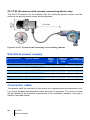

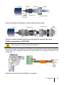
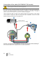


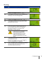

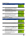
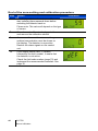
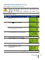


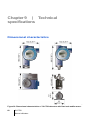


![Fio 2.0 UM ECU [ENG]](http://vs1.manualzilla.com/store/data/005638068_1-6dee15c8bb797972f1fa6aeeeee54189-150x150.png)