1
EX-94232 User’s manual
3.3
EX-94232 User’s manual
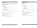
Interrupt status register
PCI controller register address map
Read the interrupt status of DI_0 and/or DI_8 channels or clear the interrupt
status register
Reset control register
The EX-94232 is in inactive state when the system power on, and should be
activated by set bit o of this register to “1” state
Address: Base+0C8h
Address: Base + 0x00h
Attribute: Read/write
Attribute: Write only
Value:
Write: any data to clear interrupt status
Value: 01
Read: bit #0= DI_0 interrupt, bit #1=DI_8 interrupt
PCI Internal special control register
EX-94232 internal control register, should be written with value 0FH before
controlling EX-94232 card
I/O control registers
Address: Base + 002h
Attribute: Read/Write
Attribute: Write only
Value:
Address: Base + 0C0h~Base + 0E0h
Value: always are 0Fh
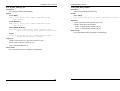
Interrupt mask control register
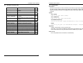
Port
Enable or disable PCI interrupt INT #A
Base+0C0h
Address: Base + 0x05h
Mode
Function
Write Write data to output port #0 (DO_0~DO_7)
Read Read back current port #0 data (DO_0~DO_7)
Attribute: Write only
Value: 10H =enable PCI INT A#
Base+0C4h
00H=disable PCI INT #A
Write Write data to output port #1 (DO_8~DO_15)
Read Read back current port #1 data (DO_8~DO_15)
Interrupt mode control register
Base+0CC Write No used
h
Read Read digital input port #0 (DI_0~DI_7)
Control the interrupt mode of DI_0 and DI_8 channels
Address: Base + 0x03h
Attribute: Write only
Base+0E0h
Write No used
Read Read digital input port #1 (DI_8~DI_15)
Value:
bit #1=0
: Disable interrupt form DI_0
bit #1=1,bit #0=0 : Enable falling edge interrupt form DI_0
bit #1=1,bit #0=1 : Enable rising edge interrupt form DI_0
bit #3=0
: Disable interrupt form DI_9
bit #3=1,bit #2=0 : Enable falling edge interrupt form DI_8
bit #3=1,bit #2=0 : Enable rising edge interrupt form DI_8
Table 3-1
13
14