1
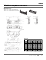
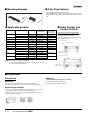
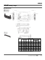
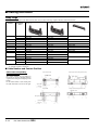
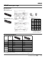
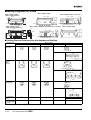
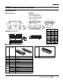
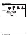
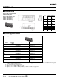
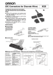
XG4
Flat Cable Connectors
The Mainstream of Circuit Board
Connectors conforming MIL Standards
with Improved Design.
■ Our new production system improves reliability.
■ Space-saving Box-type Plugs (XG4C) available.
■ IDC Plugs (XG4E) can be used for relaying.
■ An endless number of combinations can be made
using the XG-5 IDC Connectors for discrete wires,
XG8 Original Plugs, and the XG2 IDC Connectors
for PCBs.
■ The Original Plugs (XG8) and the Box-type Plugs
(XG4C) can be locked using Lock Levers.
■ Conform to MIL standards (MIL-C-83503).
■ UL standards (file No. E103202)
■ Ordering Information
Model
XG4M
XG4M-U
XG4M
XG4T
XG4A
XG4A
XG4E
XG4S
XG4C
XG4H
Appearance
MIL sockets
with strain relief
(with lock)
MIL sockets with
strain relief
MIL plugs
Plugs with
dual ports
IDC plugs with
strain relief
Box-type plugs
Board-to-board connector sockets
Page
C-3
C-4
C-5 to C-10
C-11 to C-12
C-13 to C-14
C-15 to C-16
C-17 to C-18
■ Ratings and Characteristics
Item
MIL Sockets: XG4M
Relay Plug: XG4E
MIL Plugs: XG4A
Box-type Plugs: XG4C
PCB-to-PCB Connectors: XG4H
Rated current
1A
3 A (See note 1.)
Rated voltage
250 VAC
300 VAC
Contact resistance
20 mΩ max. (at 20 mV, 100 mA max.)
Insulation resistance
1,000 MΩ min. (at 500 VDC)
Dielectric strength
500 VAC for 1 min (leakage current: 1 mA max.)
Connector insertion
1.96 N max. per contact
Contact removal
0.39 N min. (with test gauge, t= 0.64 mm)
Insertion durability
50 times (See note 2.)
Ambient temperature
Operating: −55 to 105°C (with no icing )
Note:
1. The rated current will depend on the
Socket you are using. It is 1 A using
the XG4M for example.
2. For standard 0.15- µm gold plating.
■ Materials and Finish
Item
MIL Plugs: XG4A
Box-type Plugs: XG4C
Relay Plugs: XG4E
(Strain Relief: XG4S)
MIL Sockets: XG4M
(Strain Relief: XG4T)
Housings
Fiber-glass reinforced PBT resin (UL94V-0)/black
Covers
---
Polyamide resin (UL94V-0)/black
Mating end
Brass/nickel base, 0.15-µm gold
plating (See note.)
Phosphor bronze/nickel base, 0.15-µm gold plating (See note.)
Terminal Press fit
Brass/nickel base, tin plating
Phosphor bronze/nickel base, tin plating
---
Polyamide resin (UL94V-0)/black
Contacts
Strain Reliefs
Note:
Fiber-glass reinforced PBT resin
(UL94V-0)/black
Fiber-glass reinforced PBT resin
(UL94V-0)/black
Board-to-board
Connector: XG4H
---
---
For non-standard plating, contact your OMRON representative.
■ Applicable Wires
1.27-mm pitch, 7-strand flat cable
• UL20028 (color-coded cable)
• UL2651(standard cable)
• UL20012 (folding cable)
C-1
■ Mating Combinations for XG4 and XG5
Sockets
XG4M
MIL Connectors
XG4T
Strain Reliefs
XG5M
Sockets for
Discrete
Wires
Plugs
XG4A
2-tier Plugs
Mates
with
Sockets
XG4M
MIL Sockets
Mates
with
XG4A
MIL Plugs with
Short Locks
Sockets
XG4M-U
MIL Sockets and Strain
Relief with Locks
C-2
XG4A
MIL Plugs
with Long
Locks
Mates
with
Flat Cable Connectors XG4
Plugs
XG4C
Box-type
Plugs
XG4C
XG4E
Box-type
Relay Plugs
with Long Locks Plugs
XG4S
Strain Reliefs
Plugs
XG4E
XG4C
Relay Plugs with
Box-type
Plugs
Short Locks
XG4S
Strain Reliefs
XG8W
Original
Plugs
XG8W
Original
Plugs
XG4M-U MIL Connectors with Socket Locks
■ Dimensions
■ Mating Diagrams for XG4M
XG4U
Strain Reliefs with Locks
XG4U + XG4M + XG4C (with straight terminals)
XG4U
9.5
5.6
A
B
20.2
3.3
(Locked)
XG4C
6.7
XG4M
(16.8)
1
XG4U + XG4M + XG4C (with right-angle terminals)
10.1
XG4U
XG4U
3
20.2
9.5
5.6
C
XG4C
7.4
(Unlocked)
XG4C
XG4M
(16.5)
1
9.1
Dimensions
3
XG4M-@@30 (one polarity guide)
XG4M-@@31 (all others)
Open-end cover
3
Triangular mark
Polarizing Key slot (2)
(not on models with
less than 14 contacts)
Polarity guide
6.6
10.6
Polarizing Key slot (1)
D
E
2.54
XG4M
9.3
3.3
3.8
2.54
6.1
No. of
contacts
Dimensions (mm)
A
B
C
D
E
10
26.8
13.2
26.2
17.3
10.16
14
31.8
18.2
31.2
22.3
15.24
16
34.4
20.8
33.8
24.9
17.78
20
39.5
25.9
38.9
30.0
22.86
26
47.1
33.5
46.5
37.6
30.48
30
52.2
38.6
51.6
42.7
35.56
34
57.2
43.6
56.6
47.7
40.64
40
64.9
51.3
64.3
55.4
48.26
50
77.6
64.0
77.0
68.1
60.96
60
90.3
76.7
89.7
80.8
73.66
64
95.3
81.7
94.7
85.8
78.74
■ Ordering Information
No. of
contacts
10
No. of polarity Socket and Strain Relief Sets (See note 1.) Socket with Open-end Cover (See note 2.) Strain Relief with Locks
guides
0
XG4M-1031-U
XG4M-1031
1
XG4M-1030-U
XG4M-1030
14
1
XG4M-1430-U
XG4M-1430
XG4U-1404
16
1
XG4M-1630-U
XG4M-1630
XG4U-1604
20
1
XG4M-2030-U
XG4M-2030
XG4U-2004
26
1
XG4M-2630-U
XG4M-2630
XG4U-2604
30
1
XG4M-3030-U
XG4M-3030
XG4U-3004
34
1
XG4M-3430-U
XG4M-3430
XG4U-3404
40
1
XG4M-4030-U
XG4M-4030
XG4U-4004
50
1
XG4M-5030-U
XG4M-5030
XG4U-5004
2 (See note 3.) XG4M-5031-U
XG4M-5031
60
64
XG4M-6030-U
XG4M-6030
2 (See note 3.) XG4M-6031-U
1
XG4M-6031
XG4M-6430-U
XG4M-6430
2 (See note 3.) XG4M-6431-U
1
XG4M-6431
Note: 1. With open-end cover.
2. Strain Relief sold separately.
XG4U-1004
XG4U-6004
XG4U-6404
3. Polarity guide pitch is 22.86 mm.
Flat Cable Connectors
XG4
C-3
XG4M MIL Sockets
■ Dimensions
XG4M-@@30 (one polarizing guide)
XG4M-@@31 (all others)
Strain relief
Open-end cover
Dimensions
Triangular mark
Polarizing Key slot (2) Polarity guide
(Not on models with
less than 14 contacts.)
Polarizing Key slot (1)
XG4T-@@04
Strain Relief
No of
Dimensions (mm)
contacts
A
B
10
17.3
10.16
14
22.3
15.24
16
24.9
17.78
20
30.0
22.86
26
37.6
30.48
30
42.7
35.56
34
47.7
40.64
40
55.4
48.26
50
68.1
60.96
60
80.8
73.66
64
85.8
78.74
XG4M-@@30-T (XG4M-@@30 + XG4T-@@04)
XG4M-@@31-T (XG4M-@@31 + XG4T-@@04)
MIL Socket and Strain Relief Sets
■ Ordering Information
No. of
contacts
Socket and Strain Relief Set (See note 1.)
Socket with Open-end Cover (See note 2.) Strain Relief for the XG4M
0
XG4M-1031-T
XG4M-1031
1
XG4M-1030-T
XG4M-1030
14
1
XG4M-1430-T
XG4M-1430
XG4T-1404
16
1
XG4M-1630-T
XG4M-1630
XG4T-1604
20
1
XG4M-2030-T
XG4M-2030
XG4T-2004
26
1
XG4M-2630-T
XG4M-2630
XG4T-2604
30
1
XG4M-3030-T
XG4M-3030
XG4T-3004
34
1
XG4M-3430-T
XG4M-3430
XG4T-3404
40
1
XG4M-4030-T
XG4M-4030
XG4T-4004
50
1
XG4M-5030-T
XG4M-5030
XG4T-5004
2 (See note 3.) XG4M-5031-T
XG4M-5031
1
10
60
64
No. of polarity
guides
XG4M-6030-T
XG4M-6030
2 (See note 3.) XG4M-6031-T
XG4M-6031
1
XG4M-6430-T
XG4M-6430
2 (See note 3.) XG4M-6431-T
XG4M-6431
Note: 1. With open-end cover.
2. Strain Relief sold separately.
C-4
Flat Cable Connectors XG4
XG4T-1004
XG4T-6004
XG4T-6404
3. Polarity guide pitch is 22.86 m
XG4A MIL Plugs with Long Locks
■ Dimensions
XG4A-@@31/-@@71 (With straight DIP terminals)
XG4A-@@34/-@@74 (With right-angle DIP terminals)
Straight DIP terminals
Right-angle DIP terminals
0.635 × 0.635
0.635 × 0.635
Straight DIP terminals
Right-angle DIP terminals
Two, 2.6 dia.
(M3 tapping screw hole)
Two, 2.65 dia.
Polarity slot
Polarizing Key slot
Triangular
mark
Polarizing Key slot
(not on models with
less than 14 contacts)
Mounting view (bottom view)
Right-angle terminals
0.8
+0.1
0
dia. (DIP terminals)
Dimensions
No. of
contacts
Two, 2.8 dia.
(M2.6)
Two, 3.2 dia.
(M3 tapping
screw hole)
Straight terminals
0.8
Two, 3.2 dia.
(M3 tapping
screw hole)
+0.1
0
dia. (DIP terminals)
Dimensions (mm)
A
B
D
E
F
10
32.0
17.5
10.16
C
21.8
27.9
46.4
14
37.1
22.6
15.24
26.9
33.0
51.5
16
39.6
25.2
17.78
29.5
35.6
54.1
20
44.7
30.2
22.86
34.5
40.6
59.1
26
52.3
37.9
30.48
42.2
48.3
66.8
30
57.4
42.9
35.56
47.2
53.3
71.8
34
62.5
48.0
40.64
52.3
58.4
76.9
40
70.1
55.6
48.26
59.9
66.0
84.5
50
82.8
68.3
60.96
72.6
78.7
97.2
60
95.5
81.0
73.66
85.3
91.4
109.9
64
100.6
86.1
78.74
90.4
96.5
115.0
Note: See page C-16 for details on the availability (10-contact Connectors)
and pitch (with 50, 60, or 64-contact Connectors) of polarity slots.
Flat Cable Connectors
XG4
C-5
■ Ordering Information
Use in Combination with Strain-relief Sockets.
No. of
contacts
No. of
polarizing
slots
Plugs with straight DIP terminals
Plugs with right-angle DIP terminals
0
XG4A-1071
XG4A-1074
1
XG4A-1031
XG4A-1034
14
1
XG4A-1431
XG4A-1434
16
1
XG4A-1631
XG4A-1634
20
1
XG4A-2031
XG4A-2034
26
1
XG4A-2631
XG4A-2634
30
1
XG4A-3031
XG4A-3034
34
1
XG4A-3431
XG4A-3434
40
1
XG4A-4031
XG4A-4034
50
1
XG4A-5031
XG4A-5034
2 (See note.)
XG4A-5071
XG4A-5074
1
XG4A-6031
XG4A-6034
2 (See note.)
XG4A-6071
XG4A-6074
1
XG4A-6431
XG4A-6434
2 (See note.)
XG4A-6471
XG4A-6474
10
60
64
Note: Polarizing slot pitch is 22.86 mm.
C-6
Flat Cable Connectors XG4
XG4A MIL Plugs with Short Locks
■ Dimensions
XG4A-@@32/-@@72 (With straight DIP terminals)
XG4A-@@35/-@@75 (With right-angle DIP terminals)
Straight DIP terminals
0.635 × 0.635
0.635 × 0.635
Straight DIP terminals
Right-angle DIP terminals
Right-angle DIP terminals
Two, 2.6 dia.
(M3 tapping screw hole)
Two, 2.65 dia.
Polarity slot
Polarizing Key slot
Triangular
mark
Polarizing Key slot
(not on models with
less than 14 contacts)
Mounting holes (bottom view)
Right-angle terminals
0.8
Two, 2.8 dia.
(M2.6)
Two, 3.2 dia.
(M3 tapping
screw hole)
+0.1
0
dia. (DIP terminals)
Straight terminals
0.8 +0.1
dia. (DIP terminals)
0
Two, 3.2 dia.
(M3 tapping
screw hole)
Dimensions
No. of
contacts
Dimensions (mm)
A
B
D
E
F
10
32.0
17.5
10.16
C
21.8
27.9
40.4
14
37.1
22.6
15.24
26.9
33.0
45.5
16
39.6
25.2
17.78
29.5
35.6
48.0
20
44.7
30.2
22.86
34.5
40.6
53.1
26
52.3
37.9
30.48
42.2
48.3
60.7
30
57.4
42.9
35.56
47.2
53.3
65.8
34
62.5
48.0
40.64
52.3
58.4
70.9
40
70.1
55.6
48.26
59.9
66.0
78.5
50
82.8
68.3
60.96
72.6
78.7
91.2
60
95.5
81.0
73.66
85.3
91.4
103.9
64
100.6
86.1
78.74
90.4
96.5
109.0
Note: See page C-16 for details on the availability (10-contact Connectors)
and pitch (with 50, 60, or 64-contact Connectors) of polarity slots.
Flat Cable Connectors
XG4
C-7
■ Ordering Information
Plugs with straight DIP terminals
Plugs with right-angle DIP terminals
0
XG4A-1072
XG4A-1075
1
XG4A-1032
XG4A-1035
14
1
XG4A-1432
XG4A-1435
16
1
XG4A-1632
XG4A-1635
20
1
XG4A-2032
XG4A-2035
26
1
XG4A-2632
XG4A-2635
30
1
XG4A-3032
XG4A-3035
34
1
XG4A-3432
XG4A-3435
40
1
XG4A-4032
XG4A-4035
50
1
XG4A-5032
XG4A-5035
2 (See note.)
XG4A-5072
XG4A-5075
1
XG4A-6032
XG4A-6035
2 (See note.)
XG4A-6072
XG4A-6075
1
XG4A-6432
XG4A-6435
2 (See note.)
XG4A-6472
XG4A-6475
No. of
contacts
10
60
64
No. of
polarizing
slots
Note: Polarizing slot pitch is 22.86 mm.
C-8
Flat Cable Connectors XG4
XG4A MIL Plugs without Lock Levers
■ Dimensions
XG4A-@@33/-@@73 (With straight DIP terminals)
XG4A-@@36/-@@76 (With right-angle DIP terminals)
Straight DIP terminals
Right-angle DIP terminals
0.635 × 0.635
0.635 × 0.635
Straight DIP terminals
Right-angle DIP terminals
Two, 2.6 dia.
(M3 tapping screw hole)
Two, 2.65 dia.
Polarity slot
Polarizing Key slot
Triangular mark
Polarizing Key slot
(not on models with
less than 14 contacts)
Mounting holes (bottom view)
Right-angle terminals
dia. (DIP terminals)
0.8 +0.1
0
Two, 2.8 dia.
(M2.6)
Two, 3.2 dia.
(M3 tapping
screw hole)
Straight terminals
0.8 +0.1
dia. (DIP terminals)
0
Two, 3.2 dia.
(M3 tapping
screw hole)
Dimensions
No. of
contacts
Dimensions (mm)
A
B
D
E
10
32.0
17.5
10.16
C
21.8
27.9
14
37.1
22.6
15.24
26.9
33.0
16
39.6
25.2
17.78
29.5
35.6
20
44.7
30.2
22.86
34.5
40.6
26
52.3
37.9
30.48
42.2
48.3
30
57.4
42.9
35.56
47.2
53.3
34
62.5
48.0
40.64
52.3
58.4
40
70.1
55.6
48.26
59.9
66.0
50
82.8
68.3
60.96
72.6
78.7
60
95.5
81.0
73.66
85.3
91.4
64
100.6
86.1
78.74
90.4
96.5
Note: See page C-16 for details on the availability (10-contact Connectors)
and pitch (with 50, 60, or 64-contact Connectors) of polarizing slots.
Flat Cable Connectors
XG4
C-9
■ Ordering Information
Plugs with straight DIP terminals
Plugs right-angle DIP terminals
0
XG4A-1073
XG4A-1076
1
XG4A-1033
XG4A-1036
14
1
XG4A-1433
XG4A-1436
16
1
XG4A-1633
XG4A-1636
20
1
XG4A-2033
XG4A-2036
26
1
XG4A-2633
XG4A-2636
30
1
XG4A-3033
XG4A-3036
34
1
XG4A-3433
XG4A-3436
40
1
XG4A-4033
XG4A-4036
50
1
XG4A-5033
XG4A-5036
2 (See note.)
XG4A-5073
XG4A-5076
1
XG4A-6033
XG4A-6036
2 (See note.)
XG4A-6073
XG4A-6076
1
XG4A-6433
XG4A-6436
2 (See note.)
XG4A-6473
XG4A-6476
No. of
contacts
No. of
polarizing
slots
10
60
64
Note: Polarity slot pitch is 22.86 mm.
Lock Levers
• This series of Connectors allows you to attach Lock Levers on
Right-angle Terminal Plugs after automated soldering is completed.
• Lock Levers can be easily mounted simply by manually pushing
them in.
Attachment after Soldering
• Long Levers interfere with automated mounting.
• Long Levers are in the way when boards are packed.
↓
• These problems are resolved using Connectors with Long Levers
that can be attached after soldering is completed.
XG4Z-0010
Long Lock Lever
Type
XG4Z-0011
Short Lock Lever
Model
Long Lock Levers
XG4Z-0010
Short Lock Levers
XG4Z-0011
Min. order
20
Slim Long Lock Levers XG4Z-0012
Slim Short Lock Levers XG4Z-0013
Note: The left and right Lock Levers are identical. One pair is needed
for each Plug.
C-10
Flat Cable Connectors XG4
XG4A 2-tier Plugs with Long Lock
■ Dimensions
XG4A-@@39-A/-@@79-A
(With long locks and rightangle DIP terminals)
0.635 × 0.635
Two, 2.65 dia.
Stopper
Dimensions
No. of
contacts
Two, 2.65 dia.
Dimensions (mm)
A
B
10 × 2
32.0
14 × 2
37.1
16 × 2
20 × 2
C
D
E
17.5
10.16 21.8
46.4
22.6
15.24 26.9
51.5
39.6
25.2
17.78 29.5
54.1
44.7
30.2
22.86 34.5
59.1
26 × 2
52.3
37.9
30.48 42.2
66.8
30 × 2
57.4
42.9
35.56 47.2
71.8
34 × 2
62.5
48.0
40.64 52.3
76.9
40 × 2
70.1
55.6
48.26 59.9
84.9
50 × 2
82.8
68.3
60.96 72.6
97.2
60 × 2
95.5
81.0
73.66 85.3
109.9
64 × 2
100.6 86.1
78.74 90.4
115.0
Triangular
mark
Polarity slot
Polarizing Key slot
(not on the XG4A1039-A)
Polarizing Key slot
(not on models with
less than 14 contacts)
Mounting holes (bottom view)
Two, 2.8 dia.
0.8 +0.1
dia.
0
Note: Polarizing slot pitch is 22.86 mm for 50-, 60-,
and 64-contact Connectors.
■ Ordering Information
No. of
polarizing
slots
Model
No. of
contacts
No. of
polarity slots
Model
0
XG4A-1079-A
40 × 2
1
XG4A-4039-A
1
XG4A-1039-A
14 × 2
1
XG4A-1439-A
1
XG4A-5039-A
16 × 2
1
XG4A-1639-A
20 × 2
1
XG4A-2039-A
No. of
contacts
10 × 2
26 × 2
1
XG4A-2639-A
30 × 2
1
XG4A-3039-A
34 × 2
1
XG4A-3439-A
50 × 2
60 × 2
64 × 2
Note: 1. Comes in a set with stopper and screws included.
2 (See note 2.)
XG4A-5079-A
1
XG4A-6039-A
2 (See note 2.)
XG4A-6079-A
1
XG4A-6439-A
2 (See note 2.)
XG4A-6479-A
2. Polarizing slot pitch is 22.86 mm.
Flat Cable Connectors
XG4
C-11
■ Mounting Example
■ 2-tier Plug Features
• Recommended for high-density mounting.
• MIL-compliant cable ensures faster delivery times and lower cost
than half-pitch board cable. The 2.54-mm pitch simplifies patterning.
■ Applicable Sockets
No. of contacts No. of polarity slots
10 × 2
Model
XG4M for flat cable
(See note 1.)
XG5M-N for
discrete wire
(See note 2.)
0
XG4A-1079-A XG4M-1031
XG5M-103@-N
1
XG4A-1039-A XG4M-1030
XG5M-103@-N
14 × 2
1
XG4A-1439-A XG4M-1430
XG5M-143@-N
16 × 2
1
XG4A-1639-A XG4M-1630
XG5M-163@-N
20 × 2
1
XG4A-2039-A XG4M-2030
XG5M-203@-N
26 × 2
1
XG4A-2639-A XG4M-2630
XG5M-263@-N
30 × 2
1
XG4A-3039-A XG4M-3030
XG5M-303@-N
34 × 2
1
XG4A-3439-A XG4M-3430
XG5M-343@-N
40 × 2
1
XG4A-4039-A XG4M-4030
XG5M-403@-N
50 × 2
1
XG4A-5039-A XG4M-5030
XG5M-503@-N
2 (See note 3.)
XG4A-5079-A XG4M-5031
60 × 2
1
XG4A-6039-A XG4M-6030
2 (See note 3.)
XG4A-6079-A XG4M-6031
64 × 2
1
XG4A-6439-A XG4M-6430
2 (See note 3.)
XG4A-6479-A XG4M-6431
■ Cable Number and
Contact Position
Cable and Corresponding Contact Number
The contact numbers are not marked on the Connector. Use the triangular mark as a guide when
wiring and designing circuit boards.
For the cable number, count starting from the cable
mark side as shown below.
Socket (mating side)
XG4M
Triangular mark
Cable mark
XG5M-603@-N
XG5M-643@-N
Cable number
Right-angle terminals
XG4A
Triangular mark (back)
Note: 1. Use with the supplied Strain Relief.
2. Use with the supplied Semi-cover. Hood Cover cannot be used.
3. Polarity slot pitch is 22.86 mm.
Lower connector
Upper connector
■ Precautions
Correct Use
Soldering
• Automated Soldering Conditions (Jet Flow)
Mounting
• Be sure to anchor the board with screws before mounting.
• Note that a Polarizing Key cannot be mounted on the lower Plug.
Connecting the Socket
• Before connecting the XG4M with Strain Relief, remove as much
slack from the cable as possible. Insert as shown below.
• Attach the Semi-cover before connecting the XG5M-N. It is not possible to use the Hood Cover.
C-12
Flat Cable Connectors XG4
1. Soldering temperature: 250 ±5°C
2. Continuous soldering time: Within 5 s
XG4E Relay Plugs
■ Dimensions
XG4E-@@31/-@@71
(With long locks)
XG4E-@@32/-@@72
(With short locks)
(Long locks)
(Short locks)
0.635 × 0.635
0.635 × 0.635
Open-end cover
Strain Relief
Two, 2.6 dia.
(M3 tapping screw hole)
Two, 2.65 dia.
Triangular
Polarity slot
mark
Polarizing Key slot
Polarizing Key slot
(Not on models with
less than 14 contacts.)
XG4S-@@04
Strain Relief
Dimensions
No. of
contacts
Dimensions (mm)
A
B
C
D
E
F
Long
Lock
G
Short
Lock
10
32.0
17.5
10.16
21.8
27.9
46.4
40.4
16.9
14
37.1
22.6
15.24
26.9
33.0
51.5
45.5
22.0
16
39.6
25.2
17.78
29.5
35.6
54.1
46.0
24.6
20
44.7
30.2
22.86
34.5
40.6
59.1
53.1
29.6
26
52.3
37.9
30.48
42.2
48.3
66.8
60.7
38.0
30
57.4
42.9
35.56
47.2
53.3
71.8
65.8
42.3
34
62.5
48.0
40.64
52.3
58.4
76.9
70.9
47.4
40
70.1
55.6
48.26
59.9
66.0
84.5
78.5
55.0
50
82.8
68.3
60.96
72.6
78.7
97.2
91.2
67.7
60
95.5
81.0
73.66
85.3
91.4
109.9
103.9
80.4
64
100.6
86.1
78.74
90.4
96.5
115.0
109.0
85.5
Note: See the following page for details on the availability (10-contact Connectors) and pitch
(with 50, 60, or 64-contact Connectors) of polarity slots.
Flat Cable Connectors
XG4
C-13
■ Ordering Information
Relay Plugs
Use Long-lock Plugs together with Strain-relief Sockets, and use Short-lock Plugs together with Non-strain-relief Sockets.
Long-lock Plugs with Open-end Covers
(See note 1.)
Short-lock Plugs with Open-end Covers
(See note 1.)
Strain Reliefs for XG4E
0
XG4E-1071
XG4E-1072
XG4S-1004
1
XG4E-1031
XG4E-1032
14
1
XG4E-1431
XG4E-1432
XG4S-1404
16
1
XG4E-1631
XG4E-1632
XG4S-1604
20
1
XG4E-2031
XG4E-2032
XG4S-2004
26
1
XG4E-2631
XG4E-2632
XG4S-2604
30
1
XG4E-3031
XG4E-3032
XG4S-3004
34
1
XG4E-3431
XG4E-3432
XG4S-3404
40
1
XG4E-4031
XG4E-4032
XG4S-4004
50
1
XG4E-5031
XG4E-5032
XG4S-5004
2 (See note 2.) XG4E-5071
XG4E-5072
1
No. of
contacts
10
60
64
No. of
polarizing
slots
XG4E-6031
XG4E-6032
2 (See note 2.) XG4E-6071
XG4E-6072
1
XG4E-6431
XG4E-6432
2 (See note 2.) XG4E-6471
XG4E-6472
XG4S-6004
XG4S-6404
Note: 1. Strain Relief sold separately.
2. Polarity slot pitch is 22.86 mm.
■ Cable Number and Contact Position
Cable and Corresponding
Contact Number
Socket (mated side)
Right-angle Terminal Plug (terminal side)
Triangular mark
XG4A XG4C
Triangular mark
(back)
The contact numbers are not marked on
the Connector. Use the triangular mark as
a guide when wiring and designing circuit
boards.
For the cable number, count starting from
the cable mark side as shown on the right.
Cable mark
Cable No.
Plug (XG4E)
Straight Terminal Plug (terminal side)
Triangular mark
Triangular mark
Cable mark
Cable No.
C-14
Flat Cable Connectors XG4
XG4C Box-type Plugs
■ Dimensions
XG4C-@@31/-@@71
(With straight DIP terminals)
Triangular mark
Polarizing Key slot
(Not on models with
less than 14 contacts.)
Polarity slot
Polarizing Key slot
Right-angle DIP terminals
Straight DIP terminals
Dimensions
XG4C-@@34/-@@74
(With right-angle DIP terminals)
(Straight DIP terminals)
No. of
contacts
(Right-angle DIP terminals)
Mounting holes (bottom view)
Straight DIP terminals
0.8 +0.1
dia.
0
Right-angle DIP terminals
0.8 +0.1
dia.
0
Dimensions (mm)
A
B
10
20.0
17.5
10.16
C
14
25.1
22.6
15.24
16
27.6
25.2
17.78
20
32.7
30.2
22.86
26
40.3
37.9
30.48
30
45.4
42.9
35.56
34
50.5
48.0
40.64
40
58.1
55.6
48.26
50
70.8
68.3
60.96
60
83.5
81.0
73.66
64
88.6
86.1
78.74
Note: See the following page for details on
the availability (10-contact Connectors) and pitch (with 50, 60, or 64-contact Connectors) of polarity slots.
■ Ordering Information
No. of
contacts
10
No. of
polarizing
slots
Plugs with straight DIP terminals
Plugs with right-angle DIP terminals
0
XG4C-1071
XG4C-1074
1
XG4C-1031
XG4C-1034
14
1
XG4C-1431
XG4C-1434
16
1
XG4C-1631
XG4C-1634
20
1
XG4C-2031
XG4C-2034
26
1
XG4C-2631
XG4C-2634
30
1
XG4C-3031
XG4C-3034
34
1
XG4C-3431
XG4C-3434
40
1
XG4C-4031
XG4C-4034
50
1
XG4C-5031
XG4C-5034
2 (See note 1.)
XG4C-5071
XG4C-5074
1
XG4C-6031
XG4C-6034
60
64
2 (See note 1.)
XG4C-6071
XG4C-6074
1
XG4C-6431
XG4C-6434
2 (See note 1.)
XG4C-6471
XG4C-6474
Note: 1. Polarizing slot pitch is 22.86 mm.
2. The Box-type Plug can be locked using Lock Lever II (sold separately). (See XG4Z-0002 on page C-30.)
Flat Cable Connectors
XG4
C-15
■ Mating Diagrams for XG4M
XG4T + XG4M + XG4A
XG4U + XG4M + XG4C
(With straight terminals)
XG4T
XG4U
XG4T + XG4M, + XG4C + Lock Lever
XG4M
XG4T
20.2
23.5
19.0
27
XG4C
XG4A
XG4C
10.9
XG4M
XG4Z-0002
Lock Lever
XG4M
XG4U + XG4M + XG4C
(With right-angle terminals)
XG4T + XG4M + XG8B (Unshrouded Plug) + Lock Lever
XG4T + XG4M + XG4E
XG4U
XG4U
XG4T
20.2
9
XG4M
XG4M
XG4C
24.7 28.1
18.8
9.3
XG4C
XG8B
XG4M
XG5Z-0002
Lock Lever
■ Polarity Slot and Polarizing Key Slot Number and Position
Classification
No. of contacts
10 contacts
XG4M
MIL Socket
XG4M-1031
14 contacts
XG4M-1030
16 to 40 contacts
XG4M-1430
50 to 64 contacts
XG4M-1630 to XG4M-6430
Polarizing Key slot
---
XG4M-5031, XG4M-6031, XG4M6431
Polarizing guide
XG4A
MIL Plug
XG4E
IDC Plug
XG4A-107@
XG4A-103@
XG4A-143@
XG4A-163@ to XG4A-643@
Polarizing
Key slot
XG4E-107@
XG4E-103@
XG4E-143@
XG4E-163@ to XG4E-643@
---
XG4A-507@, XG4A-607@, XG4A647@
Polarizing slot
XG4E-507@, XG4E-607@, XG4E647@
XG4C
Box-type Plug
XG4C-107@
XG4C-103@
XG4C-143@
XG4C-163@ to XG4C-643@
Polarizing slot
---
XG4C-507@, XG4C-607@, XG4C647@
Polarizing slot
No. of polarizing
guides (Polarizing
Slots)
0
No. of Polarizing
Key slot (Polarizing
Key Slots)
1
C-16
1
1
1
1
2 (H = 22.86 mm)
Flat Cable Connectors XG4
0
1
2
2
XG4H Board-to-Board Sockets
■ Dimensions
XG4H-@@31/-@@71
(With straight DIP terminals)
XG4H-3431-1
XG4H-4031-1
(With straight DIP terminals)
*Sockets with model numbers ending in -1 are available only with 34
or 40 contacts (provide kinked terminals and standoff to prevent the
Sockets from falling over).
Mounting holes (bottom view)
0.8+0.1
0
6.1
6.1
3.8
2.45
Polarizing Key slot
(Not on models with less than 10
contacts.)
3
Polarity guide
7.2 6.6
3.8
2.45
Polarizing Key slot
(Not on models with
less than 14 contacts.)
Triangular
7.1
mark
Polarizing Key slot
0.6
3
Polarizing guide Triangular
mark
2.54+0.1
B 0.1
A
7.1
7.2 6.2
3.1
B
A
2.54
B
A
3.1
2.54
XG4H-4034
(With right-angle DIP terminals)
1.27
2.54
50.8
48.26
1.27
Mounting holes (bottom view)
6.24
2.92
8.4
2.54
7.87
7.87±0.05
2±0.15
Mating end
40, 0.9 dia.
2.54±0.08
0.3 0.38
1.85
0.7
2.54+0.1
0
Dimensions
No. of
contacts
A
B
10
17.3
10.16
14
22.3
15.24
16
24.9
17.78
20
30.0
22.86
26
37.6
30.48
30
42.7
35.56
34
47.7
40.64
40
55.4
48.26
50
68.1
60.96
60
80.8
73.66
64
85.8
78.74
■ Ordering Information
No. of
contacts
No. of
polarizing
slots
Sockets with straight DIP terminals
No. of Sockets with right-angle DIP terminals
contacts
40
10
1
XG4H-1031
14
1
XG4H-1431
16
1
XG4H-1631
20
1
XG4H-2031
26
1
XG4H-2631
30
1
XG4H-3031
34
1
XG4H-3431-1
40
1
XG4H-4031-1
50
1
XG4H-5031
60
64
2 (See note.)
XG4H-5071
1
XG4H-6031
2 (See note.)
XG4H-6071
1
XG4H-6431
2 (See note.)
XG4H-6471
XG4H-4034
Note: Polarizing guide pitch is 22.86 mm.
Flat Cable Connectors
XG4
C-17
■ Mating Diagrams for XG4H
Plug
XG8W Original Plugs
XG4C Box-type Plugs
Socket
XG4H-@@31/-@@71
(With straight DIP terminals)
4.4
2.54
3.1
2.54
XG8W
2.54
2.54
6.5
XG8W
XG4C
XG4C
11.8
10.1
9.7
XG4H
7.2
XG4H
2.54
Stacking
XG4H-4034
(With right-angle DIP terminals)
15.23
6.72
0.52 Horizontal
(forward direction) XG4H
6.74
Horizontal
(reverse direction)
6.74
10.9
XG8W
Vertical
Flat Cable Connectors XG4
Vertical
---
XG4H
XG8W
XG4H
6.82
C-18
2.54
Stacking
2.54
Vertical
XG8W
15.23
XG4H
XG4H
12.9
■ Tools and Accessories (Sold Separately)
XG4Z-0004 Polarizing Key
XG4Z-0005 Coding Pin
XY2E-0002 Contact Cutting Driver
Polarity guides and slots can be used by
themselves to help prevent reverse insertion. Use the Polarizing Key as well for best
results.
(To prevent erroneous insertion)
The Contact Cutting Driver is used to cut
(twist off) a contact on the mating Plug
when using an XG4Z-0005 Coding Pin.
How to use
Insert
The Coding Pin is used to prevent confusion when many Connectors with the same
number of contacts are lined up. It can also
be used to prevent reverse insertion when
using Connectors without a shroud like the
XG8 Unshrouded Plug. The Coding Pin
can also be used with XC2, XC5, and XC6
DIN Connectors as well as with XG5 Discrete-wire IDC Connectors.
How to use
Twist
How to use
Material: PBT resin
(ULV94V-0)/white
Twist
Insert the plug
contact into the
groove on the
Driver, and twist
off the contact
from the base.
Twist
Insert
Polarizing Key
Material: PBT resin
(ULV94V-0)/white
Twist
Polarizing Key slot
Note: Each XG4Z-0004 has 4 Polarizing
Keys.
Note: 1. A contact with a Coding Pin inserted cannot be used.
2. Each XG4Z-0005 has 4 Polarizing
Keys.
Lock Lever for XG8B and XG8W Plugs (With Right-angle
Terminals)
XG5Z-0002
Use to lock Unshrouded Plugs (for XG8B and XG8W Plugs with
right-angle terminals).
Material: Polyamide resin
(UL94V-2)/natural
Lock Lever II for XG4C Plugs
XG4Z-0002
Use to lock XG4C Box-type Plugs.
Material: Polyamide resin
(UL94V-2)/natural
Lock Lever
Tab
XG4M
XG4M
Insert the tab on the Lock
Lever into the guide hole.
XG4C
Polarity guide hole
XG8B
■ Precautions
Correct Use
• Automated Soldering Conditions (Jet
Flow)
1. Soldering temperature: 250 ±5°C
2. Continuous soldering time: Within 5 s
Flat Cable Connectors
XG4
C-19
Flat Cable Connectors for PCBs
XG2
High-density mounting and speedy
termination are possible with the XG2.
■ IDC connections allow you to wire all terminals at
once without terminating the cable.
■ Can be DIP-soldered directly to the circuit board.
■ Small size (height 5.8 mm, width 6.8 mm) allows
more efficient use of circuit board space.
■ Uses a 2.54-mm grid terminal arrangement for
easier design of circuits.
■ Type: standard and reverse.
■ Uses UL94V-0 approved insulation material.
■ The IDC Tool has Attachments for all terminals.
The result is efficient, labor-saving wiring.
■ Terminal Arrangement
The contact numbers are not
marked on the Connector. If the
cables are numbered from 1 starting
from the edge, the relationship
between the wires and the terminals
would be as shown at the right.
Standard Terminal
Arrangement
Reverse Terminal
Arrangement
Cable No.
Cable No.
Cable No.
Cable No.
Cable number arrangement (top view)
■ Ratings and Characteristics
Rated current
1A
Rated voltage
250 VAC
Contact resistance
15 mΩ max. (at 20 mV, 100 mA max.)
Insulation resistance
1,000 MΩ min. (at 500 VDC)
Dielectric strength
500 VAC for 1 min (leakage current:
1 mA max.)
Operating temperature
−55 to 85°C (with no icing at low temperature)
■ Materials and Finish
Base
Contacts
Fiber-glass reinforced PBT resin
(UL94V-0)/black
Mating
end
Copper alloy/nickel base, tin plating
Terminals Copper alloy/nickel base, tin plating
Cover
Fiber-glass reinforced PBT resin
(UL94V-0)/black
■ Applicable Wires
1.27-mm pitch, AWG28, 7-strand flat cable.
• UL2651 (standard cable)
• UL20012 (folding cable)
• UL20028 (color-coded cable)
C-20
XG2A Double-row PCB Connectors
■ Dimensions
Standard Terminal Arrangement: XG2A-@@01
Reverse Terminal Arrangement: XG2A-@@02
Dimensions
No. of
contacts
Dimensions (mm)
A
B
10
17.9
10.16
14
22.9
15.24
16
25.5
17.78
20
30.6
22.86
26
38.2
30.46
30
43.3
35.56
34
48.3
40.64
40
56.0
48.26
50
68.7
60.96
60
81.4
73.66
64
86.4
78.74
Mounting holes (bottom view)
Standard terminal arrangement
Reverse terminal arrangement
0.8 +0.1
dia.
0
0.8 +0.1
dia.
0
■ Ordering Information
Appearance
No. of
contacts
Connectors with standard
terminal arrangement
Connectors with reverse terminal
arrangement
10
XG2A-1001
XG2A-1002
14
XG2A-1401
XG2A-1402
16
XG2A-1601
XG2A-1602
20
XG2A-2001
XG2A-2002
26
XG2A-2601
XG2A-2602
30
XG2A-3001
XG2A-3002
34
XG2A-3401
XG2A-3402
40
XG2A-4001
XG2A-4002
50
XG2A-5001
XG2A-5002
60
XG2A-6001
XG2A-6002
64
XG2A-6401
XG2A-6402
Note: The cover is an open-end type.
■ Precautions
Correct Use
• See page C-23 for information on special tools, such as IDC connectors.
Handling
Automated Soldering Conditions (Jet Flow)
• There is no Strain Relief for the PCB Connector. Leave enough
slack to avoid tension on the cable.
• Terminals can be press fit no matter which direction the base and
cover are facing.
1. Soldering temperature: 250 ±5°C
2. Continuous soldering time: Within 5 s
Flat Cable Connectors for PCBs
XG2
C-21
XY3A Flat Cable (UL-approved Wires)
■ Dimensions
XY3A-@@01
Standard Cables
XY3A-@@02
Folding Cables
XY3A-@@03
Color-coded Cables
Contact area Non-contact area
Core
No.
Cable mark
Insulation
color
Core
No.
Insulation
color
1
Brown
6
Blue
2
Red
7
Purple
3
Orange
8
Gray
4
Yellow
9
White
5
Green
10
Black
Note: The colors above repeat again from 11
cores.
■ Ordering Information (Order in 1-roll (61.0 m) units)
No. of cores
Standard Cable Folding Cable
(See note.)
Color-coded
Cable
Dimensions (mm)
A
B
Applicable Connector
MIL
IDC Plug
PCB
10
XY3A-1001
XY3A-1002
XY3A-1003
11.4
12.7
XG4M-10@@
XG4E-10@@
XG2A-100@
14
XY3A-1401
XY3A-1402
XY3A-1403
16.5
17.8
XG4M-1430
XG4E-143@
XG2A-140@
16
XY3A-1601
XY3A-1602
XY3A-1603
19.1
20.3
XG4M-1630
XG4E-163@
XG2A-160@
20
XY3A-2001
XY3A-2002
XY3A-2003
24.1
25.4
XG4M-2030
XG4E-203@
XG2A-200@
26
XY3A-2601
XY3A-2602
XY3A-2603
31.8
33.0
XG4M-2630
XG4E-263@
XG2A-260@
30
XY3A-3001
XY3A-3002
XY3A-3003
36.8
38.1
XG4M-3030
XG4E-303@
XG2A-300@
34
XY3A-3401
XY3A-3402
XY3A-3403
41.9
43.2
XG4M-3430
XG4E-343@
XG2A-340@
40
XY3A-4001
XY3A-4002
XY3A-4003
49.5
50.8
XG4M-4030
XG4E-403@
XG2A-400@
50
XY3A-5001
XY3A-5002
XY3A-5003
62.2
63.5
XG4M-50@@
XG4E-50@@
XG2A-500@
60
XY3A-6001
XY3A-6002
XY3A-6003
74.9
76.2
XG4M-60@@
XG4E-60@@
XG2A-600@
64
XY3A-6401
XY3A-6402
XY3A-6403
80.0
81.3
XG4M-64@@
XG4E-64@@
XG2A-640@
Note: Dimensions A and B are for the contact area of folding flat cable.
■ Ratings and Characteristics
Classification
Item
XY3A@@01
Standard
Cables
XY3A@@02
Folding
Cables
XY3A@@03
Colorcoded
Cables
UL file No.
UL2651
UL20012
Max. operating voltage
300 V
150 V
150 V
80°C
105°C
Max. operating temperature 105°C
U:20028
Max. conductor resistance
224 Ω/km (at 20°C)
Dielectric strength
2,000 VAC, 50/60 Hz for 1 min
Min. insulation resistance
5 kΩ-km (at 20°C)
■ Materials
Conductor AWG28 (7/0,127), tin plated, soft copper wire
Insulation Heat-resistant vinyl
C-22
Flat Cable Connectors XG4/XG2
■ Special Tools
XY2B-0002
IDC Tool (Attachments sold separately)
■ IDC Tool Attachments for XG4M and XG2A
XY2B-1006
Attachment for the XG2A
XY2B-1007
Attachment for the XG4M
Operation
XG4M-series Connectors must be placed face down
into the locator slot of the Attachment. (With the XG2A
Series, place the terminal block in the Attachment.)
Insert the cable until it is flush against the cable stopper. Connections are made by pulling the handle
towards you until it stops. For details on operation, see
the user’s manual supplied with the IDC Tool.
Locator groove
Cable stopper
Combinations
IDC Tool
XY2B-0002
Attachment
Applicable Socket
XY2B-1007
XG4M (All contacts)
XY2B-1006
XG2A (All contacts)
■ IDC Tool Attachments for XG4E
XY2B-14@@
Spacer for the XG4E
XY2B-1004
Attachment for the XG4E
Operation
XG4E-series Connectors must be placed
face down into the locator slot of the
Attachment. Insert the cable until it is
flush against the cable stopper. Next set
the proper spacer for the Plug. Connections are made by pulling the handle
towards you until it stops.
Ordering Information
IDC Tool
XY2B-0002
Attachment
XY2B-1004
Spacer
Applicable Plug
XY2B-1401
XG4E-10@1/-10@2
XG4E-1431/-1432
XY2B-1402
XG4E-1631/-1632
XG4E-2031/-2032
XY2B-1403
XG4E-2631/-2632
XG4E-3031/-3032
XY2B-1404
XG4E-3431/-3432
XY2B-1405
XG4E-4031/-4032
XY2B-1406
XG4E-50@1/-50@2
XY2B-1407
XG4E-60@1/-60@2
XG4E-54@1/-64@2
Spacer
XG4E
Attachment
Cable
Cover
Flat Cable Connectors
XG4/XG2
C-23
XG5
IDC Connectors for Discrete Wires
Trouble-free discrete-wire termination
with IDC Sockets that accommodate MIL
Plugs.
■ Two-slot, IDC construction and insulation barrel
offer high reliability and large-current (3 A) discrete wiring capability.
■ Adaptable to a variety of covers for space-saving
and discrete wire termination.
■ By using the simple, unique lock-lever system,
these Connectors can be locked to either the
XG8B/XG8W Unshrouded Plugs (with right-angle
terminals) or XG4C Box-type Plugs.
■ Conforms to UL standards (file no. E 103202) and
CSA standards (file no. LR 62678).
■ Construction
Solderless Contact
Cover (Semi-cover or Hood
Cover) Semi-cover shown here.
Socket (with polarizing guide)
Wire can be connected without
stripping cable insulation.
Lance
Insulation barrel
IDC contacts
Two-slot connection
Polarizing guide
■ Ratings and Characteristics ■ Current and Temperature Characteristics
Rated voltage
300 VAC
Contact resistance
20 mΩ max. (at 20 mV, 100
mA max.)
Insulation resistance
1,000 MΩ min. (at
500 VDC)
Dielectric strength
650 VAC for 1 min (leakage
current: 1 mA max.)
Connector insertion
1.96 N max. per contact
Contact removal
0.29 N min. (with test
gauge, 0.64 x 0.64 mm)
Insertion durability
(See note.)
50 times
Ambient temperature
Operating: −55 to 85°C
(with no icing)
Note:
20
wires
Temp. rise limit
Housing
Fiber-glass reinforced PBT resin
(UL94V-0)/black
Contacts
Cover
Mating end
Phosphor-bronze/nickel base, 0.15-µm
gold plating (See note.)
Terminals
Phosphor-bronze/nickel base, 2.0-µm
solder plating
Fiber-glass reinforced polyamide resin
(UL94V-0)/black
Cable tie
C-24
10 wires
10 wires
Polyamide resin (UL94V-0)/natural
For non-standard plating, contact your OMRON representative.
Flow rate = (no. of contacts used) × 100%
(total no. of contacts)
UL1061 AWG24
UL1007 AWG26
Temp. rise limit
2 wires
2
wires
Current flow (A)
For standard 0.15-mm gold plating
■ Materials and Finish
Note:
20 wires
UL1061 AWG24 (XG5M-2032-N)
UL1007 AWG26 (XG5M-2035-N)
Rise in temperature (°C)
3A
Rise in temperature (°C)
Use the temperature data shown below as a reference for selecting current values and wires.
Rated current
Current flow (A)
■ Applicable Wires and Contact Sizes
Size #1
Size #2
Note:
AWG24 (For UL-1061) Insulation outside diameter: 1.1 to 1.3 mm}
Core structure: 7 strands
or more
AWG28 or AWG26
(For UL-1007)
The contact numbers are marked on the contact insulation
barrels.
■ Configuration
Assembly
Socket
Wire
Connections
Discrete wires
Cover
Assembled unit
Semi-cover
Double rows
with polarity
guide
(lockable)
Double-row
Assembled
Hood Cover
IDC Tool
Simple IDC Tool
Vertical
Double rows
with polarity
guide
(lockable)
Horizontal
Double rows
with polarity
guide
(lockable)
■ Applicable Plugs
XG4A
Flat Cable MIL Plugs with
Long Locks
■ Press-fitting (XG5M) and
Crimping
XG4A
Flat Cable Plugs without
Lock Lever (Lock Levers
mounted later)
XG4A
Flat Cable Double-row
Plugs
The advantages of press fitting over crimping are as follows:
• Overall cost is lower because less manhours are required (no wire stripping and
easier inspections).
• Consistent quality improves yield.
• Contacts built into the housing simplify
parts control.
XG4E
IDC Flat Cable Plugs
Note:
XG4C
Flat Cable Box-type Plugs
XG8W/XG8B
Double-row Unshrouded
Plugs
1. Plug dimensions are listed on the Plug's page.
2. When using the XG4A or XG4C, the number of XG4A or XG4C's slots must be the same as the number of XG5M-N polarity guides.
IDC Connectors for Discrete Wires
XG5
C-25
XG5M-N Double-row Sockets
■ Dimensions
Models with no polarizing guide
XG5M-1031-N (size #1)
XG5M-1034-N (size #2)
Size no.
Dimensions
No. of
Dimensions (mm)
contacts
A
B
Models with polarizing guide
XG5M-@@32-N (size #1)
XG5M-@@33-N (size #1)
XG5M-@@35-N (size #2)
XG5M-@@36-N (size #2)
Polarizing guide
10
17.3
10.16
14
22.3
15.24
16
24.9
17.78
20
30.0
22.86
26
37.6
30.48
30
42.7
35.56
34
47.7
40.64
40
55.4
48.26
50
68.1
60.96
60
80.8
73.66
64
85.8
78.74
■ Ordering Information
Appearance
No. of
contacts
10
No. of
polarizing
guide
Size #1 (See note 1.)
Size #2 (See note 2.)
0
XG5M-1031-N
1
XG5M-1032-N
XG5M-1034-N
XG5M-1035-N
14
1
XG5M-1432-N
XG5M-1435-N
16
1
XG5M-1632-N
XG5M-1635-N
20
1
XG5M-2032-N
XG5M-2035-N
26
1
XG5M-2632-N
XG5M-2635-N
30
1
XG5M-3032-N
XG5M-3035-N
34
1
XG5M-3432-N
XG5M-3435-N
40
1
XG5M-4032-N
XG5M-4035-N
50
1
XG5M-5032-N
XG5M-5035-N
2
XG5M-5033-N
XG5M-5036-N
60
1
XG5M-6032-N
XG5M-6035-N
2
XG5M-6033-N
XG5M-6036-N
64
1
XG5M-6432-N
XG5M-6435-N
2
XG5M-6433-N
XG5M-6436-N
Note: 1. The 10-contact XG5M-1031-N and XG5M-1034-N have no polarizing guides. The distance between slots is 22.86 mm for the two guides
on 50, 60, and 64-contact Connectors.
2. See the previous page for Plug information.
3. Applicable wire is AWG24 (UL1061) for size #1.
4. Applicable wire is AWG28 to AWG26 (UL-1007) for size #2. For details, see page C-24.
C-26
IDC Connectors for Discrete Wires XG5
XG5S Semi-covers
■ Dimensions
XG5S-@@01
Dimensions
No. of Dimensions (mm)
contacts
A
5
17.3
7
22.3
8
24.9
10
30.0
13
37.6
15
42.7
17
47.7
20
55.4
25
68.1
30
80.8
32
85.8
■ Ordering Information
No. of
contacts
Model
Order in
Applicable Connector
multiples of
5
XG5S-0501
7
XG5S-0701
10
XG5M-143@-N
XG5M103@-N
8
XG5S-0801
XG5M-163@-N
10
XG5S-1001
XG5M-203@-N
13
XG5S-1301
XG5M-263@-N
15
XG5S-1501
XG5M-303@-N
17
XG5S-1701
XG5M-343@-N
20
XG5S-2001
XG5M-403@-N
25
XG5S-2501
XG5M-503@-N
30
XG5S-3001
XG5M-603@-N
32
XG5S-3201
XG5M-643@-N
Note: One Semi-cover is used per row. Each XG5M Connector requires two semi-covers.
■ Assembled Dimensions (Socket with Semi-cover)
Dimensions
No. of Dimensions (mm)
contacts
A
B
10
17.3
32.0
14
22.3
37.1
16
24.9
39.6
20
30.0
44.7
26
37.6
52.3
30
42.7
57.4
34
47.7
62.5
40
55.4
70.1
50
68.1
82.8
60
80.8
95.5
64
85.8
100.6
Original Plug + Semicover + Lock Lever
MIL Plug + Semi-cover
IDC Connectors for Discrete Wires
XG5
C-27
XG5S Hood Covers
■ Dimensions
Vertical/XG5S-@@12
(Left and right halves)
Dimensions
No. of
contacts
Dimensions (mm)
A
B
20
30.0
23.8
8.8
C
26
37.6
31.4
11.4
30
42.7
36.5
15.1
Horizontal/XG5S-@@22
(Left and right halves)
Dimensions
No. of
contacts
■ Ordering Information
Appearance
Vertical
No. of contacts
(double rows)
Model (See note.) Order in
20
XG5S-2012
26
30
34
---
40
Horizontal
Model (See note.) Order in
multiples of
10
multiples of
---
---
XG5S-2612
---
---
XG5S-3012
---
---
---
XG5S-3422
10
---
---
XG5S-4022
50
---
---
XG5S-5022
60
---
---
XG5S-6022
Note: Includes cable tie.
C-28
IDC Connectors for Discrete Wires XG5
Dimensions (mm)
A
B
C
D
34
47.7
38.7
32.0
14.6
40
55.4
40.7
34.0
16.6
50
68.1
44.1
39.4
20.0
60
80.8
47.4
42.8
23.4
■ Assembled Dimensions (Socket and Hood Cover)
Vertical Hood Cover
Assembled Unit
MIL Plug + Vertical Hood Cover
Dimensions
No. of Dimensions (mm)
contacts
A
B
20
30.0
44.7
26
37.6
52.3
30
42.7
57.4
Horizontal Hood Cover
Assembled Unit
MIL Plug + Horizontal Hood Cover
Dimensions
No. of
contacts
Dimensions (mm)
A
B
C
D
E
F
34
47.7
39.0
45.7
62.5
46.4
53.1
40
55.4
41.0
47.7
70.1
48.4
55.1
50
68.1
46.4
51.1
82.8
53.8
58.5
60
80.8
49.8
54.4
95.5
57.2
61.8
IDC Connectors for Discrete Wires
XG5
C-29
■ XG5 Accessories
Lock Levers
Lock Levers
XG5Z-0002
XG4Z-0002
Use to lock Unshrouded Plugs (XG8B and XG8W, with rightangle terminals).
Use to lock XG4C Box-type Plugs.
Material: Polyamide resin
(UL94V-2)/natural
Material: Polyamide resin
(UL94V-2)/natural
Mounting the Lock Lever
For Sockets with polarity guides, mount the
Lock Lever to the tab to lock the Socket to the
Unshrouded Plug as shown in the diagram on
the right.
Model
XG5Z-0002
Order in
multiples of
10
XG4Z-0002
Spare Contacts
XG5W-0031-N (Size #1)
XG5W-0034-N (Size #2)
Size no.
Model
XG5W-0031-N
Order in
multiples of
100
XG5W-0034-N
Note: 1. These Contacts can be used
as replacements if a wrong
connection is made.
2. The applicable wire for size
No. 1 is AWG24 (UL-1061).
The applicable wire for size
No. 2 is AWG26 to AWG24
(UL-1007).
See page C-24 for details.
C-30
IDC Connectors for Discrete Wires XG5
■ XG5 IDC Tools
■ Tools
Simple IDC Tool
Simple Wire IDC Tool Set
XY2B-7006
XY2B-2104-N
This tool is a compact, light-weight model,
ideal for use in the laboratory or for maintenance.
Specifications
This Wire IDC Tool Set is designed for XG5
Discrete-wire Connectors.
Applicable con- XG5M-N
nector
Applicable wire AWG24 to AWG28
(with an insulation
outer diameter of 1.1
to 1.3 mm)
Dimensions
25 (W) × 100 (L) × 80 (H)
Weight
Approx. 180 g
■ Tools for the XG5
Contact Removal Tool
XY2E-0001
Contact
Removal Tool
Specifications
Stroke
13 mm
Motor speed
83/100 rpm (50/60 Hz)
Feed pitch
2.54 mm
Operation
Foot switch
Weight
About 6 kg
Rated voltage 0.5 A, 100 VAC (50/60 Hz)
Fuse
1A
Dimensions
120 × 200 × 225 mm (W ×
H × D)
Note: For function and operation details,
see the user’s manual for the Pressure Welder provided separately.
Applicable Connectors and
Wires
Used to remove from the housing, contacts
which are wrong.
Applicable Connector
Size No.
Replacing Contacts
Use only this tool to remove incorrect IDC
contacts.
1. Remove the cover.
2. Insert the tool into the housing lance
holes and push the lance into the housing.
3. Pull out the contact while holding the
lance down.
4. Insert a new contact.
Applicable wires
UL file
No.
Size
[No. of wires/
diameter (mm)]
Cross-sectional area
(mm)
Covering
diameter
(mm)
XG5M-@@31-N
XG5M-@@32-N
XG5M-@@33-N
No. 1
UL1061
AWG24 [7/0.203]
0.21
1.10
XG5M-@@34-N
XG5M-@@35-N
XG5M-@@36-N
No. 2
UL1007
AWG26 [7/0.16]
0.13
1.30
AWG28 [7/0.127]
0.09
1.22
Note: Use only wires specified in the table above.
XY2E-0001
Lance hole
Housing
IDC Connectors for Discrete Wires
XG5
C-31
■ Precautions
Correct Use
IDC Connectors
• For best results, use only the XG5 IDC
Tool.
• Contact your OMRON representative for
details on the XG5 IDC Tool.
• Check the Contact size (No. 1 or No 2)
and wire size before connecting.
• OMRON has a IDC Tool Reference Manual. Contact your OMRON representative
to request a copy.
Mounting the Cover
Mounting the Hood Cover
• The cover is used to protect the connection position and prevent shorting out.
Vertical Hood Cover
Mounting the Semi-cover
Slot
Semi-cover
Claw
• See the above diagram.
1. Insert part A of the Semi-cover into part
B of the Socket.
2. Push the claws on both sides of the
Semi-cover onto the Socket.
3. Make sure the claws are firmly inserted
in the slots.
4. To protect the wires, use cable ties to
bind wires that may be subject to tension even when a Semi-cover is used.
• See the above diagram.
1. Insert the claws of part A of the Hood
Cover into the slots.
2. Insert claws B on the Hood cover into
part C on the other part of the Hood
Cover.
3. Wrap the wires with a cable tie.
Cable tie
Horizontal Hood Cover
• Follow the mounting procedure for the
vertical cover.
• The left and right parts of the cover are
different. Assemble carefully.
C-32
IDC Connectors for Discrete Wires XG5
XG5M-N Double-row Socket Contact
Numbers
Triangular mark Terminal
Polarizing guide
numbers
Applicable Plugs
• XG4A, XG4C and XG8 are recommended.
• XG4C and XG8 Plugs do not have locks.
To prevent accidental removal, use a Lock
Lever (XG4Z-0002, XG5Z-0002). (Lock
Levers cannot be used with XG8W
Straight Terminal Connectors.)
• When mounting the XG8 Original Plug
(with right-angle terminals) to a circuit
board, be sure that the cover is positioned
off the board as shown below.
Original Plug
Cover
Board
XG5
XG4M Terminal Numbers
Triangular mark
7 mm max. Edge
Not marked on connector.
• The Contact numbers on the Double-row
Assembled Socket match the numbers on
the XG4M Flat Cable MIL Socket. (See
the above diagrams.)
• When making IDC connections on the
Double-row Assembled Connector, use
the polarity guide to distinguish the front
and back. (Note: The 10-contact Connector does not have a guide.)
IDC Connectors for Discrete Wires
XG5
C-33
Original Plugs
XG8
Original Plug that can be used in a wide
range of applications.
■ Can use as a Plug for different Sockets.
■
■
■
■
■
Applicable Sockets:
XG4M Flat Cable Connector
XG5 Discrete-wire IDC Connector
OMRON's unique production system maintains
low costs.
Straight Terminal Plugs are easily divided into the
desired number of contacts.
Through-holes handle 0.8-mm wires.
With Double-row Plugs with right-angle terminals,
block-base soldering improves productivity while
lock levers simplify locking (excluding XG8V and
XG8W Plugs with straight terminals).
Simply cut to divide (excluding XG8W Right-angle
Plugs).
■ Connectors
Model
XG8V
Appearance
Single-row plugs with
straight terminals
XG8W
Single-row plugs with
right-angle terminals
Double-row plugs with
straight terminals
Page
C-35
C-36
Model
XG8A
XG8B
Appearance
Single-row plugs with
straight terminals
Page
C-37
Single-row plugs with
right-angle terminals
■ Ratings and Characteristics
Rated current
3 A (See note 1.)
Rated voltage
300 VAC
Contact resistance
20 mΩ max. (at 20 mV, 100 mA max.) (See note 2.)
Insulation resistance
1,000 MΩ min. (at 500 VDC)
Double-row plugs with
straight terminals
Double-row plugs with
right-angled terminals
Double-row plugs with
right-angle terminals
■ Materials and Finish
Model
XG8V and XG8W (See
note.)
Base
Contacts
Fiber-glass reinforced PBT resin (UL94V-0)/black
Mating
end
Terminal
Brass/nickel base, 0.15-µm
gold plating
Brass/nickel base, tin plating
Dielectric strength 650 VAC for 1 min (leakage current: 1 mA max.)
Ambient tempera- Operating: −55 to 105°C (with no icing)
ture
Note:
1. The rated current will depend on the Socket you are using. It is 1 A using the XG4M for example.
2. The contact resistance is measured with the Plug mated to an XG5M-N.
Note:
XG8A and XG8B
Brass/nickel base, 0.15µm gold plating
Brass/nickel base, tin
plating
Two types of contacts and mating ends, one with gold
plating and the other with tin plating, are available.
■ Applicable Sockets
XG8W and XG8B
(Double Row)
XG4M Flat Cable Connectors (Sockets)
XG4H Board-to-Board Connectors (Sockets)
XG5M-N Discrete-wire IDC Connectors
(Double-row Sockets)
C-34
XG8V Single-row Original Plugs
■ Dimensions
Dimensions
XG8V-@@31
(With gold-plated straight terminals)
XG8V-@@41
(With tin-plated straight terminals)
No. of
contacts
Mounting holes (bottom view)
0.8 +0.1
dia.
0
0.635 × 0.635
Dimensions (mm)
A
B
3
7.6
5.08
4
10.2
7.62
5
12.7
10.16
6
15.2
12.70
7
17.8
15.24
8
20.3
17.78
10
25.4
22.86
12
30.5
27.94
13
33.0
30.48
15
38.1
35.56
16
40.6
38.10
17
43.2
40.64
20
50.8
48.26
36
91.4
88.90
Dimensions
XG8V-@@34
(With gold-plated right-angle terminals)
XG8V-@@44
(With tin-plated right-angle terminals)
Mounting holes (bottom view)
No. of
contacts
Dimensions (mm)
A
dia.
0.8 +0.1
0
4 to 11
0.635 × 0.635
B
3
7.6
5.08
4
10.2
7.62
5
12.7
10.16
6
15.2
12.70
7
17.8
15.24
8
20.3
17.78
10
25.4
22.86
12
30.5
27.94
13
33.0
30.48
15
38.1
35.56
16
40.6
38.10
17
43.2
40.64
20
50.8
48.26
36
91.4
88.90
■ Ordering Information
Appearance
No. of contacts
Plugs with straight terminals
Model (gold plated)
Plugs with right-angle terminals
Model (tin plated)
Model (gold plated)
Model (tin plated)
3
XG8V-0331
XG8V-0341
XG8V-0334
XG8V-0344
4
XG8V-0431
XG8V-0441
XG8V-0434
XG8V-0444
5
XG8V-0531
XG8V-0541
XG8V-0534
XG8V-0544
6
XG8V-0631
XG8V-0641
XG8V-0634
XG8V-0644
7
XG8V-0731
XG8V-0741
XG8V-0734
XG8V-0744
8
XG8V-0831
XG8V-0841
XG8V-0834
XG8V-0844
10
XG8V-1031
XG8V-1041
XG8V-1034
XG8V-1044
12
XG8V-1231
XG8V-1241
XG8V-1234
XG8V-1244
13
XG8V-1331
---
XG8V-1334
---
15
XG8V-1531
---
XG8V-1534
---
16
XG8V-1631
XG8V-1641
XG8V-1634
XG8V-1644
17
XG8V-1731
---
XG8V-1734
---
20
XG8V-2031
XG8V-2041
XG8V-2034
XG8V-2044
36
XG8V-3631
XG8V-3641
XG8V-3634
XG8V-3644
Original Plugs
XG8
C-35
XG8W Original Plugs for MIL Connectors
■ Dimensions
XG8W-@@31
(With gold-plated straight terminals)
XG8W-@@41
(With tin plated straight terminals)
Dimensions
Mounting holes (bottom view)
0.635 × 0.635
0.635 × 0.635
■ Ordering Information
Plugs with straight terminals
Model (tin plated)
Plugs with right-angle terminals
Model (gold plated)
Model (tin plated)
10
XG8W-1031
XG8W-1041
---
---
14
XG8W-1431
XG8W-1441
---
---
16
XG8W-1631
XG8W-1641
---
---
20
XG8W-2031
XG8W-2041
XG8W-2034
XG8W-2044
26
XG8W-2631
XG8W-2641
XG8W-2634
XG8W-2644
30
XG8W-3031
XG8W-3041
XG8W-3034
XG8W-3044
34
XG8W-3431
XG8W-3441
XG8W-3434
XG8W-3444
40
XG8W-4031
XG8W-4041
XG8W-4034
XG8W-4044
50
XG8W-5031
XG8W-5041
XG8W-5034
XG8W-5044
60
XG8W-6031
XG8W-6041
---
---
C-36
Original Plugs XG8
B
12.7
10.16
14
17.8
15.24
16
20.3
17.78
20
25.4
22.86
26
33.0
30.48
30
38.1
35.56
34
43.2
40.46
40
50.8
48.26
50
63.5
60.96
60
76.2
73.66
Dimensions (mm)
A
Mounting holes (bottom view)
4 to 11
Model (gold plated)
A
10
No. of
contacts
dia.
0.8 +0.1
0
No. of contacts
Dimensions (mm)
Dimensions
XG8W-@@34
(With gold-plated right-angle terminals)
XG8W-@@44
(With tin-plated right-angle terminals)
Appearance
No. of
contacts
dia.
0.8 +0.1
0
B
20
25.4
22.86
26
33.0
30.48
30
38.1
35.56
34
43.2
40.64
40
50.8
48.26
50
63.5
60.96
XG8A (Single-row)/XG8B (Double-row)
Original Plugs for MIL Connectors
■ Dimensions
Single-row Plugs
XG8A-5031
(With straight terminals)
Mounting holes (bottom view)
0.8 +0.1
dia.
0
0.635 × 0.635
XG8A-5034
(With right-angle terminals)
Mounting holes (bottom view)
0.8 +0.1
dia.
0
0.635 × 0.635
4 to 11
Double-row Plugs
XG8B-0131
(With straight terminals)
Mounting holes (bottom view)
0.8 +0.1
dia.
0
0.635 × 0.635
XG8B-0134
(With right-angle terminals)
Mounting holes (bottom view)
0.8 +0.1
dia.
0
0.635 × 0.635
4 to 11
■ Ordering Information
Terminal type
No. of contacts
Plugs with straight terminals
Model (gold plated)
Plugs with right-angle terminals
Model (gold plated)
50 (Single-row)
XG8A-5031
XG8A-5034
100 (Double-row)
XG8A-0131
XG8A-0134
Original Plugs
XG8
C-37
■ Accessories
Mounting the Lock Lever
■ Precautions
Lock Levers
Insert the tab on the Lock Lever into the
hole on a Socket with a polarity guide. In
this way, it can be locked with XG8W Rightangle Terminal Plugs.
Correct Use
XG5Z-0002
Can be used to lock XG8W Double-row
Right-angle Terminal Plugs to XG4M Flat
Cables and XG5M-N Discrete-wire IDC
Connectors.
Polarizing guide hole XG4M
XG8
Dividing the XG8W (with
Straight Terminals), XG8V,
XG8A, and XG8B
• Using a Cutter, make a cut on the slot as
indicated by the dotted line in the diagram. Then fold the Plug manually in the
direction of the arrows.
They cannot be used with XG8W Doublerow Straight Terminal Plugs or XG8V Single-row Plugs.
Tab
Lock lever
Note: Order the above model in multiples of
the minimum order.
(1) Using a cutter,
make a cut along
the dotted line.
(2) Manually fold in
the direction of the
arrows.
Automated Soldering
Conditions (Jet Flow)
1. Soldering temperature: 250 ±5°C
2. Continuous soldering time: Within 5 s
■ Ordering
Procedure
• Contact your OMRON representative if
you require a product with a non-standard
number of contacts.
C-38
Original Plugs XG8