1
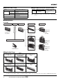
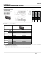
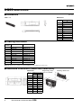
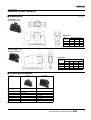
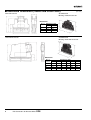
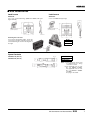
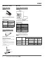
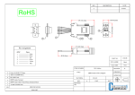
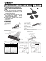
XG5
IDC Connectors for Discrete Wires
Trouble-free discrete-wire termination
with IDC Sockets that accommodate MIL
Plugs.
■ Two-slot, IDC construction and insulation barrel
offer high reliability and large-current (3 A) discrete wiring capability.
■ Adaptable to a variety of covers for space-saving
and discrete wire termination.
■ By using the simple, unique lock-lever system,
these Connectors can be locked to either the
XG8B/XG8W Unshrouded Plugs (with right-angle
terminals) or XG4C Box-type Plugs.
■ Conforms to UL standards (file no. E103202).
(Except XG5S models)
RoHS Compliant
■ Terminology
• Insulation barrel
• Insulation height
Wire
Refers to the part of a
contact that crimps the
insulating sheath of a
wire.
Refers to the height of the
insulation barrel after
crimping or IDC pressing.
Insulation
height
• Lance
Insulation barrel
Lance 2-slot IDC pressing
Mating end
Refers to the lance-like
projections arranged on a
contact to secure it in the housing.
• U-slot
Refers to the part where the wire and the contact connect to each
other. It is called a U-slot because of its shape.
■ Construction
Solderless Contact
Cover (Semi-cover or Hood Cover)
Semi-cover shown here.
Socket (with polarizing guide)
Wire can be connected without
stripping cable insulation.
Lance
Insulation barrel
IDC contacts
Two-slot connection
Polarizing guide
■ Ratings and Characteristics ■ Current and Temperature Characteristics
Rated voltage
300 VAC
Contact resistance
20 mΩ max. (at 20 mV, 100
mA max.)
Insulation resistance
1,000 MΩ min. (at
500 VDC)
Dielectric strength
650 VAC for 1 min (leakage
current: 1 mA max.)
Total insertion force
1.96 N max. per contact
Removal force
0.29 N min. (with test
gauge, 0.64 x 0.64 mm)
Insertion durability
50 times
Ambient operating
temperature
Operating: −55 to 85°C
(with no icing)
Use the temperature data shown below as a reference for selecting current values and wires.
UL1061 AWG24 (XG5M-2032-N)
UL1007 AWG26 (XG5M-2035-N)
20 wires
20
wires
Temp. rise limit
10 wires
10 wires
2
wires
Rise in temperature (°C)
1 A (AWG28), 2 A (AWG26),
3 A (AWG24)
Rise in temperature (°C)
Rated current
Flow rate = (no. of contacts used) × 100%
(total no. of contacts)
UL1061 AWG24
UL1007 AWG26
Temp. rise limit
2 wires
Current flow (A)
Current flow (A)
1
■ Materials and Finish
Housing
■ Applicable Wires and Contact Sizes
Fiber-glass reinforced PBT resin
(UL94V-0)/black
Contacts
Mating end
Phosphor-bronze/nickel base, 0.15-µm
gold plating
Terminals
Phosphor-bronze/nickel base, 2.0-µm
solder plating
Cover
Fiber-glass reinforced polyamide resin
(UL94V-0)/black
Cable tie
Polyamide resin (UL94V-0)/natural
Size #1
AWG24 (For UL1061)
Size #2
AWG28 or AWG26
(For UL1007)
Note:
Insulation outside diameter: 1.1 to 1.3 mm
Core structure: 7 strands
or more
The contact numbers are marked on the contact insulation
barrels.
■ Configuration
Assembly
Socket
Wire
Connections
Discrete wires
Cover
Assembled unit
Semi-cover
Double rows
with polarity
guide
(lockable)
Double-row
Assembled
Hood Cover
IDC Tool
Simple IDC Tool
Vertical
Double rows
with polarity
guide
(lockable)
Horizontal
Double rows
with polarity
guide
(lockable)
■ Applicable Plugs
XG4A
Flat Cable MIL Plugs with
Long Locks
XG4A
Flat Cable Plugs without
Lock Lever (Lock Levers
mounted later)
XG4A
Flat Cable Double-row
Plugs
XG4E
IDC Flat Cable Plugs
Long Locks
XG4C
Flat Cable Box-type Plugs
XG8W/XG8B
Double-row Unshrouded
Plugs
Note:
1. Plug dimensions are listed on the Plug's page.
2. When using the XG4A or XG4C, the number of XG4A or XG4C's slots must be the same as the number of XG5M-N polarity guides.
2
IDC Connectors for Discrete Wires XG5
XG5M-N Double-row Sockets
■ Dimensions
(Unit: mm)
Models with no polarizing guide
XG5M-1031-N (size #1)
XG5M-1034-N (size #2)
Size no.
Dimensions
No. of
Dimensions (mm)
contacts
A
B
Models with polarizing guide
XG5M-@@32-N (size #1)
XG5M-@@33-N (size #1)
XG5M-@@35-N (size #2)
XG5M-@@36-N (size #2)
Polarizing guide
10
17.3
10.16
14
22.3
15.24
16
24.9
17.78
20
30.0
22.86
26
37.6
30.48
30
42.7
35.56
34
47.7
40.64
40
55.4
48.26
50
68.1
60.96
60
80.8
73.66
64
85.8
78.74
■ Ordering Information
Appearance
No. of
contacts
10
No. of
polarizing
guide
Size #1 (See note 1.)
Size #2 (See note 2.)
0
XG5M-1031-N
XG5M-1034-N
1
XG5M-1032-N
XG5M-1035-N
14
1
XG5M-1432-N
XG5M-1435-N
16
1
XG5M-1632-N
XG5M-1635-N
20
1
XG5M-2032-N
XG5M-2035-N
26
1
XG5M-2632-N
XG5M-2635-N
30
1
XG5M-3032-N
XG5M-3035-N
34
1
XG5M-3432-N
XG5M-3435-N
40
1
XG5M-4032-N
XG5M-4035-N
50
1
XG5M-5032-N
XG5M-5035-N
2
XG5M-5033-N
XG5M-5036-N
1
XG5M-6032-N
XG5M-6035-N
2
XG5M-6033-N
XG5M-6036-N
1
XG5M-6432-N
XG5M-6435-N
2
XG5M-6433-N
XG5M-6436-N
60
64
Note: 1. The 10-contact XG5M-1031-N and XG5M-1034-N have no polarizing guides. The distance between slots is 22.86 mm for the two guides
on 50, 60, and 64-contact Connectors.
2. See the previous page for Plug information.
3. Applicable wire is AWG24 (UL1061) for size #1.
4. Applicable wire is AWG28 to AWG26 (UL1007) for size #2. For details, see the previous page.
IDC Connectors for Discrete Wires
XG5
3
XG5S Semi-covers
■ Dimensions
(Unit: mm)
XG5S-@@01
Dimensions
No. of Dimensions (mm)
contacts
A
5
17.3
7
22.3
8
24.9
10
30.0
13
37.6
15
42.7
17
47.7
20
55.4
25
68.1
30
80.8
32
85.8
■ Ordering Information
No. of
contacts
Model
Applicable Connector
5
XG5S-0501
XG5M-103@-N
7
XG5S-0701
XG5M-143@-N
8
XG5S-0801
XG5M-163@-N
10
XG5S-1001
XG5M-203@-N
13
XG5S-1301
XG5M-263@-N
15
XG5S-1501
XG5M-303@-N
17
XG5S-1701
XG5M-343@-N
20
XG5S-2001
XG5M-403@-N
25
XG5S-2501
XG5M-503@-N
30
XG5S-3001
XG5M-603@-N
32
XG5S-3201
XG5M-643@-N
Note: One Semi-cover is used per row. Each XG5M Connector requires two semi-covers.
■ Assembled Dimensions (Socket with Semi-cover)
Dimensions
No. of Dimensions (mm)
contacts
A
B
4
10
17.3
32.0
14
22.3
37.1
16
24.9
39.6
20
30.0
44.7
26
37.6
52.3
30
42.7
57.4
34
47.7
62.5
40
55.4
70.1
50
68.1
82.8
60
80.8
95.5
64
85.8
100.6
IDC Connectors for Discrete Wires XG5
Original Plug + Semicover + Lock Lever
MIL Plug + Semi-cover
XG5S Hood Covers
■ Dimensions
(Unit: mm)
Vertical/XG5S-@@12
(Left and right halves)
Dimensions
No. of
contacts
Dimensions (mm)
A
B
20
30.0
23.8
8.8
C
26
37.6
31.4
11.4
30
42.7
36.5
15.1
Horizontal/XG5S-@@22
(Left and right halves)
Dimensions
No. of
contacts
Dimensions (mm)
A
B
C
D
34
47.7
38.7
32.0
14.6
40
55.4
40.7
34.0
16.6
50
68.1
44.1
39.4
20.0
60
80.8
47.4
42.8
23.4
■ Ordering Information
Appearance
Vertical
Horizontal
No. of contacts
(double rows)
Model (See note.)
Model (See note.)
20
XG5S-2012
---
26
XG5S-2612
---
30
XG5S-3012
---
34
---
XG5S-3422
40
---
XG5S-4022
50
---
XG5S-5022
60
---
XG5S-6022
Note: Includes cable tie.
IDC Connectors for Discrete Wires
XG5
5
■ Assembled Dimensions (Socket and Hood Cover)
Vertical Hood Cover
(Unit: mm)
Assembled Unit
MIL Plug + Vertical Hood Cover
Dimensions
No. of Dimensions (mm)
contacts
A
B
20
30.0
44.7
26
37.6
52.3
30
42.7
57.4
Horizontal Hood Cover
Assembled Unit
MIL Plug + Horizontal Hood Cover
Dimensions
No. of
contacts
6
IDC Connectors for Discrete Wires XG5
Dimensions (mm)
A
B
C
D
E
F
34
47.7
39.0
45.7
62.5
46.4
53.1
40
55.4
41.0
47.7
70.1
48.4
55.1
50
68.1
46.4
51.1
82.8
53.8
58.5
60
80.8
49.8
54.4
95.5
57.2
61.8
■ XG5 Accessories
Lock Levers
Lock Levers
XG5Z-0002
XG4Z-0002
Use to lock Unshrouded Plugs (XG8B and XG8W, with rightangle terminals).
Use to lock XG4C Box-type Plugs.
Material: Polyamide resin
(UL94V-2)/natural
Material: Polyamide resin
(UL94V-2)/natural
Mounting the Lock Lever
For Sockets with polarity guides, mount the
Lock Lever to the tab to lock the Socket to the
Unshrouded Plug as shown in the diagram on
the right.
Model
XG5Z-0002
XG4Z-0002
Spare Contacts
XG5W-0031-N (Size #1)
XG5W-0034-N (Size #2)
Size no.
Model
XG5W-0031-N
XG5W-0034-N
Note: 1. These Contacts can be used
as replacements if a wrong
connection is made.
2. The applicable wire for size
No. 1 is AWG24 (UL1061).
The applicable wire for size
No. 2 is AWG26 to AWG24
(UL1007).
See page 2 for details.
IDC Connectors for Discrete Wires
XG5
7
■ XG5 IDC Tools
■ Tools
Simple IDC Tool
Simple Wire IDC Tool Set
XY2B-7006
XY2B-2104-N
This tool is a compact, light-weight model,
ideal for use in the laboratory or for maintenance.
Specifications
This Wire IDC Tool Set is designed for XG5
Discrete-wire Connectors.
Applicable con- XG5M-N
nector
Applicable wire AWG24 to AWG28
(with an insulation
outer diameter of 1.1
to 1.3 mm)
Dimensions
25 (W) × 100 (D) × 80 (H)
Weight
Approx. 180 g
■ Tools for the XG5
Contact Removal Tool
Specifications
Stroke
13 mm
Motor speed
83/100 rpm (50/60 Hz)
Feed pitch
2.54 mm
Operation
Foot switch
Weight
About 6 kg
Rated voltage 0.5 A, 100 VAC (50/60 Hz)
Fuse
1A
Dimensions
120 × 200 × 225 mm (W ×
D × H)
XY2E-0001
Note: For function and operation details,
see the user’s manual for the Pressure Welder provided separately.
Lance Holding
Part
Applicable Connectors and
Wires
Used to remove from the housing, contacts
which are wrong.
Replacing Contacts
Use only this tool to remove incorrect IDC
contacts.
1. Remove the cover.
2. Insert the tool into the housing lance
holes and push the lance into the housing.
3. Pull out the contact while holding the
lance down.
4. Insert a new contact.
Applicable Connector
Applicable wires
UL file
No.
Size
[No. of wires/
diameter (mm)]
Cross-sectional area
(mm)
Covering
diameter
(mm)
XG5M-@@31-N
XG5M-@@32-N
XG5M-@@33-N
No. 1
UL1061
AWG24 [7/0.203]
0.21
1.1
XG5M-@@34-N
XG5M-@@35-N
XG5M-@@36-N
No. 2
UL1007
AWG26 [7/0.16]
0.13
1.3
AWG28 [7/0.127]
0.09
1.2
Note: Use only wires specified in the table above.
XY2E-0001
Lance hole
Housing
8
Size No.
IDC Connectors for Discrete Wires XG5
■ Precautions
Correct Use
Mounting the Hood Cover
XG5M-N Double-row Socket Contact
Numbers
Vertical Hood Cover
IDC Connectors
• For best results, use only the XG5 IDC
Tool.
• Contact your OMRON representative for
details on the XG5 IDC Tool.
• Check the Contact size (No. 1 or No 2)
and wire size before connecting.
• OMRON has a IDC Tool Reference Manual. Contact your OMRON representative
to request a copy.
Triangular mark Contact
Polarizing guide
numbers
Mounting the Cover
• The cover is used to protect the connection position and prevent shorting out.
Mounting the Semi-cover
XG4M Contact Numbers
• See the above diagram.
1. Insert the claws of part A of the Hood
Cover into the slots.
2. Insert claws B on the Hood cover into
part C on the other part of the Hood
Cover.
3. Wrap the wires with a cable tie.
Slot
Triangular mark
Not marked on connector.
Semi-cover
Claw
Cable tie
• See the above diagram.
1. Insert part A of the Semi-cover into part
B of the Socket.
2. Push the claws on both sides of the
Semi-cover onto the Socket.
3. Make sure the claws are firmly inserted
in the slots.
4. To protect the wires, use cable ties to
bind wires that may be subject to tension even when a Semi-cover is used.
Horizontal Hood Cover
• Follow the mounting procedure for the
vertical cover.
• The left and right parts of the cover are
different. Assemble carefully.
• The Contact numbers on the Double-row
Assembled Socket match the numbers on
the XG4M Flat Cable MIL Socket. (See
the above diagrams.)
• When making IDC connections on the
Double-row Assembled Connector, use
the polarity guide to distinguish the front
and back. (Note: The 10-contact Connector does not have a guide.)
Applicable Plugs
• XG4A, XG4C and XG8 are recommended.
• XG4C and XG8 Plugs do not have locks.
To prevent accidental removal, use a Lock
Lever (XG4Z-0002, XG5Z-0002). (Lock
Levers cannot be used with XG8W
Straight Terminal Connectors.)
• When mounting the XG8 Original Plug
(with right-angle terminals) to a circuit
board, be sure that the cover is positioned
off the board as shown below.
Original Plug
Cover
Board
XG5
7 mm max. Edge
IDC Connectors for Discrete Wires
XG5
9
• Application examples provided in this document are for reference only. In actual applications, confirm equipment functions and safety before using the product.
• Consult your OMRON representative before using the product under conditions which are not described in the manual or applying the product to nuclear control systems, railroad
systems, aviation systems, vehicles, combustion systems, medical equipment, amusement machines, safety equipment, and other systems or equipment that may have a serious
influence on lives and property if used improperly. Make sure that the ratings and performance characteristics of the product provide a margin of safety for the system or
equipment, and be sure to provide the system or equipment with double safety mechanisms.
Note: Do not use this document to operate the Unit.
OMRON Corporation
ELECTRONIC AND MECHANICAL COMPONENTS COMPANY
Contact: www.omron.com/ecb
Cat. No. G042-E1-01
0412(0412)(O)