1
User’s
Manual
WX11
AddObserver
IM WX11-01E
8th Edition
Thank you for purchasing the WX11 AddObserver. The AddObserver includes two
software applications, AddObserver Builder and AddObserver Panel.
This user’s manual contains information primarily about the functions and operating
procedures of the AddObserver Builder. To ensure proper use of the instrument, please
read this manual thoroughly before beginning operation. For operating instructions for
AddObserver Panel, see chapter 2 of the “WX83 AddObserver Runtime (IM WX83-01E).”
After reading this manual, keep it in a convenient location for quick reference in the event
a question arises.
Notes
• The contents of this manual are subject to change without prior notice as a result of
improvements in the software’s performance and functions.
• Every effort has been made in the preparation of this manual to ensure the accuracy
of its contents. However, should you have any questions or find any errors, please
contact your nearest YOKOGAWA representative.
• Copying or reproduction of all or any part of the contents of this manual without the
permission of Yokogawa Electric Corporation is strictly prohibited.
• This software may not be used concurrently on multiple PCs. Use by more than one
user is also prohibited.
• This software may not be forwarded to any third party.
• Yokogawa Electric Corporation does not warrant this product after it has been opened,
unless there are physical defects in the original setup disk or this document.
• YOKOGAWA will not accept responsibility for any damage caused directly or indirectly
as a result of using this software.
• The license number will not be reissued. Please keep the licence number in a safe
place.
Trademarks
• DAQWORX, DAQLOGGER, and DAQEXPLORER are registered trademarks or
trademarks of Yokogawa Electric Corporation.
• Microsoft, Windows, and Windows Vista are registered trademarks or trademarks of
Microsoft Corporation in the United States and/or other countries.
• Adobe and Acrobat are registered trademarks or trademarks of Adobe Systems
Incorporated.
• Company and product names that appear in this manual are registered trademarks or
trademarks of their respective holders.
• The company and product names used in this manual are not accompanied by the
registered trademark or trademark symbols (® and ™).
Revisions
•
•
•
•
•
•
•
•
1st Edition
2nd Edition
3rd Edition
4th Edition
5th Edition
6th Edition
7th Edition
8th Edition
July 2003
August 2005
March 2006
June 2007
March 2008
January 2009
January 2011
October 2011
8th Edition : October 2011 (YK)
All Rights Reserved, Copyright © 2003 Yokogawa Electric Corporation
IM WX11-01E
Software License Agreement
IMPORTANT - PLEASE READ CAREFULLY BEFORE INSTALLING OR USING:
THANK YOU VERY MUCH FOR SELECTING SOFTWARE OF YOKOGAWA ELECTRIC CORPORATION ("YOKOGAWA"). BY INSTALLING OR OTHERWISE USING THE
SOFTWARE PRODUCT, YOU AGREE TO BE BOUND BY THE TERMS AND CONDITIONS OF THIS AGREEMENT. IF YOU DO NOT AGREE, DO NOT INSTALL NOR USE
THE SOFTWARE PRODUCT AND PROMPTLY RETURN IT TO THE PLACE OF PURCHASE FOR A REFUND, IF APPLICABLE.
Software License Agreement
1. Scope
This Agreement applies to the following software products and associated documentation of Yokogawa (collectively, "Software Product"). Unless otherwise provided by
Yokogawa, this Agreement applies to the updates and upgrades of the Software Product which may be provided by Yokogawa.
Software Product: DAQWORX (It is limited to each software that you bought).
2. Grant of License
2.1 Subject to the terms and conditions of this Agreement, Yokogawa hereby grants to you a non-exclusive and non-transferable right to use the Software Product on a
single or, the following specified number of, computer(s) and solely for your internal operation use, in consideration of full payment by you to Yokogawa of the license
fee separately agreed upon.
Granted number of License: 1 (one)
2.2 Unless otherwise agreed or provided by Yokogawa in writing, the following acts are prohibited:
a) to reproduce the Software Product, except for one archival copy for backup purpose, which shall be maintained with due care subject to this Agreement;
b)to sell, lease, distribute, transfer, pledge, sublicense, make available via the network or otherwise convey the Software Product or the license granted herein to any
other person or entity;
c) to use the Software Product on any unauthorized computer via the network;
d)to cause, permit or attempt to dump, disassemble, decompile, reverse-engineer, or otherwise translate or reproduce the Software Product into source code or other
human readable format, or to revise or translate the Software Product into other language and change it to other formats than that in which Yokogawa provided;
e) to cause, permit or attempt to remove any copy protection used or provided in the Software Product; or
f) to remove any copyright notice, trademark notice, logo or other proprietary notices or identification shown in the Software Product.
2.3 Any and all technology, algorithms, know-how and process contained in the Software Product are the property or trade secret of Yokogawa or licensors to Yokogawa.
Ownership of and all the rights in the Software Product shall be retained by Yokogawa or the licensors and none of the rights will be transferred to you hereunder.
2.4 You agree to maintain the aforementioned property and trade secret of Yokogawa or licensors and key codes in strict confidence, not to disclose it to any party other
than your employees, officers, directors or similar staff who have a legitimate need to know to use the Software Product and agreed in writing to abide by the obligations
hereunder.
2.5 Upon expiration or termination of this Agreement, the Software Product and its copies, including extracts, shall be returned to Yokogawa and any copies retained in your
computer or media shall be deleted irretrievably. If you dispose of media in which the Software Product or its copy is stored, the contents shall be irretrievably deleted.
2.6 The Software Product may contain software which Yokogawa is granted a right to sublicense or distribute by third party suppliers, including affiliates of Yokogawa ("Third
Party Software"). If suppliers of the Third Party Software ("Supplier") provide special terms and conditions for the Third Party Software which differ from this Agreement,
the special terms and conditions separately provided by Yokogawa shall prevail over this Agreement. Some software may be licensed to you directly by Supplier.
2.7 The Software Product may contain open source software ("OSS"), for which the special terms and conditions separately provided by Yokogawa shall take precedence
over this Agreement.
3. Restrictions on Application
3.1 Unless otherwise agreed in writing between you and Yokogawa, the Software Product is not intended, designed, produced or licensed for use in relation to aircraft
operation or control, ship navigation or marine equipment control, or ground facility or device for support of the aforesaid operation or control, or for use in relation
to rail facility, nuclear related facility, radiation-related equipment, or medical equipment or facility, or under any other circumstances which may require high safety
standards.
3.2 If the Software Product is used for the abovementioned purposes, neither Yokogawa nor Supplier assumes liability for any claim or damage arising from the said use
and you shall indemnify and hold Yokogawa, Supplier, their affiliates, subcontractors, officers, directors, employees and agents harmless from any liability or damage
whatsoever, including any court costs and attorney's fees, arising out of or related to the said use.
4. Limited Warranty
4.1 The Software Product shall be provided to you on an "as is" basis at the time of delivery and except for physical damage to the recording medium containing the
Software Product, Yokogawa and Supplier shall disclaim all of the warranties whatsoever, express or implied, and all liabilities therefrom. If any physical defect is found
on the recording medium not later than twelve (12) months from delivery, Yokogawa shall replace such defective medium free of charge, provided that the defective
medium shall be returned to the service office designated by Yokogawa at your expense within the said twelve (12) months. THIS LIMITED WARRANTY PROVIDED
IN THIS CLAUSE IS IN LIEU OF ALL OTHER WARRANTIES OF ANY KIND WHATSOEVER AND YOKOGAWA HEREBY DISCLAIMS ALL OTHER WARRANTIES
RELATING TO THE SOFTWARE PRODUCT, WHETHER EXPRESSED OR IMPLIED, INCLUDING WITHOUT LIMITATION, ANY IMPLIED WARRANTIES OF
MERCHANTABILITY, FITNESS FOR ANY PARTICULAR PURPOSE, NON-INFRINGEMENT, QUALITY, FUNCTIONALITY, APPROPRIATENESS, ACCURACY,
RELIABILITY AND RECENCY. IN NO EVENT SHALL YOKOGAWA WARRANT THAT THERE IS NO INCONSISTENCY OR INTERFERENCE BETWEEN THE
SOFTWARE PRODUCT AND OTHER SOFTWARE NOR SHALL BE LIABLE THEREFOR. The warranty provisions of the applicable law are expressly excluded to the
extent permitted.
4.2 At the sole discretion of Yokogawa, Yokogawa may upgrade the Software Product to the new version number ("Upgrade") and make it available to you at your expense
or free of charge as Yokogawa deems fit. In no event shall Yokogawa be obliged to upgrade the Software Product or make the Upgrade available to you.
4.3 Certain maintenance service may be available for some types of Software Product at Yokogawa's current list price. Scope and terms and conditions of the maintenance
service shall be subject to those separately provided by Yokogawa. Unless otherwise provided in Yokogawa catalogues or General Specifications, maintenance services
will be available only for the latest version and the immediately preceding version. In no event will service for the immediately preceding version be available for more
than 5 years after the latest version has been released. In addition, no service will be provided by Yokogawa for the Software Product which has been discontinued for
more than 5 years. Notwithstanding the foregoing, maintenance service may not be available for non-standard Software Product. Further, in no event shall Yokogawa
provide any service for the Software Product which has been modified or changed by any person other than Yokogawa.
ii
IM WX11-01E
Software License Agreement
5. Infringement
5.1 If you are warned or receive a claim by a third party that the Software Product in its original form infringes any third party's patent (which is issued at the time of delivery
of the Software Product), trade mark, copyright or other intellectual property rights ("Claim"), you shall promptly notify Yokogawa thereof in writing.
5.2 If the infringement is attributable to Yokogawa, Yokogawa will defend you from the Claim at Yokogawa's expense and indemnify you from the damages finally granted
by the court or otherwise agreed by Yokogawa out of court. The foregoing obligation and indemnity of Yokogawa shall be subject to that i) you promptly notify Yokogawa
of the Claim in writing as provided above, ii) you grant to Yokogawa and its designees the full authority to control the defense and settlement of such Claim and iii) you
give every and all necessary information and assistance to Yokogawa upon Yokogawa's request.
5.3 If Yokogawa believes that a Claim may be made or threatened, Yokogawa may, at its option and its expense, either a) procure for you the right to continue using the
Software Product, b) replace the Software Product with other software product to prevent infringement, c) modify the Software Product, in whole or in part, so that it
become non-infringing, or d) if Yokogawa believes that a) through c) are not practicable, terminate this Agreement and refund you the paid-up amount of the book value
of the Software Product as depreciated.
5.4 Notwithstanding the foregoing, Yokogawa shall have no obligation nor liability for, and you shall defend and indemnify Yokogawa and its suppliers from, the Claim, if the
infringement is arising from a) modification of the Software Product made by a person other than Yokogawa, b) combination of the Software Product with hardware or
software not furnished by Yokogawa, c) design or instruction provided by or on behalf of you, d) not complying with Yokogawa's suggestion, or e) any other causes not
attributable to Yokogawa.
5.5 This section states the entire liability of Yokogawa and its suppliers and the sole remedy of you with respect to any claim of infringement of a third party's intellectual
property rights. Notwithstanding anything to the contrary stated herein, with respect to the claims arising from or related to the Third Party Software or OSS, the special
terms and conditions separately provided for such Third Party Software or OSS shall prevail.
6. Limitation of Liability
6.1 EXCEPT TO THE EXTENT THAT LIABILITY MAY NOT LAWFULLY BE EXCLUDED IN CONTRACT, YOKOGAWA AND SUPPLIERS SHALL NOT BE LIABLE TO ANY
PERSON OR LEGAL ENTITY FOR LOSS OR DAMAGE, WHETHER DIRECT, INDIRECT, SPECIAL, INCIDENTAL, CONSEQUENTIAL OR EXEMPLARY DAMAGES,
OR OTHER SIMILAR DAMAGES OF ANY KIND, INCLUDING WITHOUT LIMITATION, DAMAGES FOR LOSS OF BUSINESS PROFITS, BUSINESS INTERRUPTION,
LOSS OR DESTRUCTION OF DATA, LOSS OF AVAILABILITY AND THE LIKE, ARISING OUT OF THE USE OR INABILITY TO USE OF THE SOFTWARE PRODUCT,
OR ARISING OUT OF ITS GENERATED APPLICATIONS OR DATA, EVEN IF ADVISED OF THE POSSIBILITY OF SUCH DAMAGES, WHETHER BASED IN
WARRANTY (EXPRESS OR IMPLIED), CONTRACT, STRICT LIABILITY, TORT (INCLUDING NEGLIGENCE), OR ANY OTHER LEGAL OR EQUITABLE GROUNDS.
IN NO EVENT YOKOGAWA AND SUPPLIER'S AGGREGATE LIABILITY FOR ANY CAUSE OF ACTION WHATSOEVER (INCLUDING LIABILITY UNDER CLAUSE
5) SHALL EXCEED THE DEPRECIATED VALUE OF THE LICENSE FEE PAID TO YOKOGAWA FOR THE USE OF THE CONCERNED PART OF THE SOFTWARE
PRODUCT. If the Software Product delivered by Yokogawa is altered, modified or combined with other software or is otherwise made different from Yokogawa
catalogues, General Specifications, basic specifications, functional specifications or manuals without Yokogawa's prior written consent, Yokogawa shall be exempted
from its obligations and liabilities under this Agreement or law.
6.2 Any claim against Yokogawa based on any cause of action under or in relation to this Agreement must be given in writing to Yokogawa within three (3) months after the
cause of action accrues.
7. Export Control
You agree not to export or provide to any other countries, whether directly or indirectly, the Software Product, in whole or in part, without prior written consent of Yokogawa.
If Yokogawa agrees such exportation or provision, you shall comply with the export control and related laws, regulations and orders of Japan, the United States of America,
and any other applicable countries and obtain export/import permit and take all necessary procedures under your own responsibility and at your own expense.
8. Audit; Withholding
8.1 Yokogawa shall have the right to access and audit your facilities and any of your records, including data stored on computers, in relation to the use of the Software
Product as may be reasonably necessary in Yokogawa's opinion to verify that the requirements of this Agreement are being met.
8.2 Even after license being granted under this Agreement, should there be any change in circumstances or environment of use which was not foreseen at the time of
delivery and, in Yokogawa's reasonable opinion, is not appropriate for using the Software Product, or if Yokogawa otherwise reasonably believes it is too inappropriate
for you to continue using the Software Product, Yokogawa may suspend or withhold the license provided hereunder.
9. Assignment
If you transfer or assign the Software Product to a third party, you shall expressly present this Agreement to the assignee to ensure that the assignee comply with this
Agreement, transfer all copies and whole part of the Software Product to the assignee and shall delete any and all copy of the Software Product in your possession
irretrievably. This Agreement shall inure to the benefit of and shall be binding on the assignees and successors of the parties.
10. Termination
Yokogawa shall have the right to terminate this Agreement with immediate effect upon notice to you, if you breach any of the terms and conditions hereof. Upon termination of
this Agreement, you shall promptly cease using the Software Product and, in accordance with sub-clause 2.5, return or irretrievably delete all copies of the Software Product,
certifying the same in writing. In this case the license fee paid by you for the Software Product shall not be refunded. Clauses 2.4 and 2.5, 3, 5, 6 and 11 shall survive any
termination of this Agreement.
11. Governing Law; Disputes
This Agreement shall be governed by and construed in accordance with the laws of Japan.
Any dispute, controversies, or differences which may arise between the parties hereto, out of, in relation to or in connection with this Agreement ("Dispute") shall be resolved
amicably through negotiation between the parties based on mutual trust. Should the parties fail to settle the Dispute within ninety (90) days after the notice is given from either
party to the other, the Dispute shall be addressed in the following manner:
(i) If you are a Japanese individual or entity, the Dispute shall be brought exclusively in the Tokyo District Court (The Main Court) in Japan.
(ii)If you are not a Japanese individual or entity, the Dispute shall be finally settled by arbitration in Tokyo, Japan in accordance with the Commercial Arbitration Rules
of the Japan Commercial Arbitration Association. All proceedings in arbitration shall be conducted in the English language, unless otherwise agreed. The award of
arbitration shall be final and binding upon both parties, however, each party may make an application to any court having jurisdiction for judgment to be entered on
the award and/or for enforcement of the award.
12. Miscellaneous
12.1 This Agreement supersedes all prior oral and written understandings, representations and discussions between the parties concerning the subject matter hereof to the
extent such understandings, representations and discussions should be discrepant or inconsistent with this Agreement.
12.2 If any part of this Agreement is found void or unenforceable, it shall not affect the validity of the balance of the Agreement, which shall remain valid and enforceable
according to its terms and conditions. The parties hereby agree to attempt to substitute for such invalid or unenforceable provision a valid or enforceable provision that
achieves to the greatest extent possible the economic, legal and commercial objectives of the invalid or unenforceable provision.
12.3 Failure by either party to insist on performance of this Agreement or to exercise a right when entitled does not prevent such party from doing so at a later time, either in
relation to that default or any subsequent one.
End of document
IM WX11-01E
iii
Overview of This Manual
Structure of This Manual
This manual consists of four chapters and an index as shown below.
Chapter
1
Title
Before Using the Software
2
Creating Monitor Screens
with AddObserver Builder
Saving and Opening Monitor
Screens
3
4
Responding to Error Messages
Index
Description
Gives an overview of the AddObserver. Also
provides a list of PC system requirements and
instructions for installing the software.
Provides instructions for creating original monitor
screens using AddObserver Builder.
Provides instructions for saving, opening, and
checking the data for monitor screens that were
created using AddObserver Builder.
Lists all error messages and their corrective
actions, and explains how to check the version of
AddObserver Builder.
An alphabetical index.
Scope of This Manual
This manual does not explain the basic operations of your PC's operating system (OS).
For specific information on your operating system please refer to the user’s guide that
came with it.
Conventions Used in This Manual
• Unit
K: Denotes 1024. Example: 100 KB
M: Denotes 1024 K. Example: 10 MB
G: Denotes 1024 M. Example: 2 GB
• Bolded Items
Items set in boldface mainly refer to on-screen interface elements such as menus,
commands, dialog boxes, and buttons, or keys on the keyboard.
• Headings Used for Descriptions of Operations
The following headings are used to distinguish procedural instructions from other
information given in chapters 1 through 4.
Procedure
iv
Note
This subsection contains the operating procedure used to carry out
the function described in the current section. All procedures are
written with inexperienced users in mind; experienced users may
not need to carry out all the steps.
Calls attention to information that is important for proper operation
of the instrument.
IM WX11-01E
1
Contents
Software License Agreement............................................................................................................. ii
Overview of This Manual.................................................................................................................. iv
2
Chapter 1 Before Using the Software
1.1 Overview of the AddObserver............................................................................................... 1-1
1.2 PC System Requirements and Supported Monitor Servers................................................. 1-3
Chapter 2 Creating Monitor Screens with AddObserver Builder
2.1 Starting and Exiting AddObserver Builder............................................................................ 2-1
2.2 The AddObserver Builder Startup Screen............................................................................ 2-3
2.3 Creating New Monitor Screens............................................................................................. 2-5
2.4 Entering Host and Channel Settings..................................................................................... 2-6
2.5 Protection for Out Object.................................................................................................... 2-13
2.6 Creating Labels................................................................................................................... 2-14
2.7 Creating Lines..................................................................................................................... 2-17
2.8 Creating Rectangles........................................................................................................... 2-19
2.9 Creating Ellipses................................................................................................................. 2-21
2.10 Creating Arcs...................................................................................................................... 2-23
2.11 Creating Polygons.............................................................................................................. 2-26
2.12 Creating Value Rectangles................................................................................................. 2-28
2.13 Creating Indicators.............................................................................................................. 2-31
2.14 Creating Meters.................................................................................................................. 2-33
2.15 Creating Meter Sets............................................................................................................ 2-36
2.16 Creating Trend Graphs....................................................................................................... 2-39
2.17 Creating Pictures................................................................................................................ 2-42
2.18 Creating Monitor Windows.................................................................................................. 2-45
2.19 Creating Buttons................................................................................................................. 2-47
2.20 Creating Numeric Out Windows......................................................................................... 2-48
2.21 Creating Selectable Out Objects........................................................................................ 2-50
2.22 Creating Temperature Controller Parts............................................................................... 2-52
2.23 Creating Extended Trend Graph......................................................................................... 2-56
2.24 Creating Extended Indicator............................................................................................... 2-58
2.25 Creating X-Y Graph............................................................................................................ 2-60
2.26 Creating Alarm Summary.................................................................................................... 2-62
2.27 Creating Color Change (Rectangle and Ellipse) Objects.................................................... 2-64
2.28 Creating String Change Objects......................................................................................... 2-66
2.29 Adding Monitor Windows.................................................................................................... 2-68
2.30 Editing Objects.................................................................................................................... 2-69
2.31 Arranging Objects............................................................................................................... 2-75
2.32 Changing Monitor Screen Display Properties..................................................................... 2-77
Chapter 3 Saving and Operating Monitor Screens
3.1 Checking and Fixing Data from Created Monitor Screens................................................... 3-1
3.2 Saving Monitor Screens and Outputting Files...................................................................... 3-3
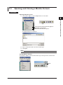
3.3 Opening and Closing a Monitor Screen................................................................................ 3-5
IM WX11-01E
3
4
Index
Contents
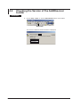
Chapter 4 Responding to Error Messages
4.1 List of Messages................................................................................................................... 4-1
4.2 Checking the Version of the AddObserver builder................................................................ 4-2
Index
vi
IM WX11-01E
Chapter 1
Before Using the Software
1.1
1
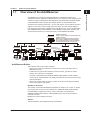
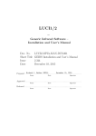
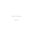
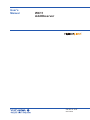
Overview of the AddObserver
AddObserver
MXLOGGER
GateEye
DAQLOGGER
RS-232/RS-422A
Converter
AddObserver Panel
Reads in screen setting files and configuration
files created on AddObserver Builder, displays
the corresponding monitor screen, and displays
acquired measurement data on that screen.
RS-232/RS-422A or
RS-232/RS-485 Converter
Data
acquisition
Data
acquisition
Ethernet
Data
acquisition
Hub
Ethernet
Temperature
Controller
Network camera,
DX, MV, CX
MX
DAQ32 Plus
Data acquisition
Data acquisition
RS-232
Data acquisition
RS-422A
Data acquisition
Ethernet
VIEW RECORDER VR200
µR, VR, DX, MV, CX, DARWIN
Data acquisition
RS-232
RS-422A
or
RS-485
Ethernet
Data
acquisition
GP-IB
DARWIN
DAQEXPLORER
Data
acquisition
RS-232
RS-232
Data acquisition
Ethernet
MV, DX, CX
AddObserver Builder
The software’s main functions are as follows:
• Allows you to create and edit monitor screens to be used for monitoring data on
AddObserver Panel.
• Creates the two types of files needed for monitor screens; .gob files for monitor
settings, and .cob files for configuration.
• Connects to the DAQ32 Plus, DAQEXPLORER, DAQLOGGER, or MXLOGGER
monitor server, GateCONTROL and GateEye via Ethernet, and accesses the server's
channel information.
• Allows you to easily assign channels or alarms to monitor screen objects including
meters, trend graphs, and signals.
Number of Channels
The number of channels that AddObserver Builder can assign is up to 1600. To assign
the channels, the PC that is running DAQ32 Plus, DAQEXPLORER, DAQLOGGER
or MXLOGGER is registered as a host, and the channels on the DAQ32 Plus,
DAQEXPLORER, DAQLOGGER, or MXLOGGER monitor servers are assigned to
channels 0 to 1599.
Multiple PCs can be registered as hosts.
Alarms
Alarms specified on the assigned channels are indicated.
IM WX11-01E
2
3
4
AddObserver Builder
Creates a screen setting file and configuration file.
Ethernet
GateCONTROL
Before Using the Software
The AddObserver includes two software applications, AddObserver Builder and
AddObserver Panel. AddObserver Builder allows you to create your own original monitor
screens for viewing measurement data gathered by the DAQ32 Plus, DAQEXPLORER,
or DAQLOGGER monitor servers, the package software for YOKOGAWA’s data
acquisition and recording instruments. You can add “objects” such as meters and trend
graphs to your monitor screen, assign channels to them, and even include images of
such things as the test facility. AddObserver Panel allows you to connect to the DAQ32
Plus, DAQEXPLORER, DAQLOGGER, or MXLOGGER monitor server, GateEye and
view the monitor screens you created previously on the AddObserver Builder.
1-1
Index
1.1 Overview of the AddObserver
AddObserver Panel
The operating instructions for this software are available in chapter 1.1 of the “WX83
AddObserver Runtime User’s Manual (IM WX83-01E).”
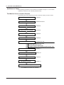
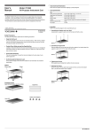
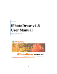
The Monitor Screen Creation Process
The following flow chart outlines the process involved in creating a monitor screen.
Start AddObserver Builder
Open a monitor screen
Select host PCs
Select channels to be displayed
Section 2.1
Sections 2.3 and 3.3
Section 2.4
Section 2.4
Enter host and channel settings
Section 2.4
Protect Out Object
Section 2.5
Create a monitor screen
Sections 2.6 to 2.32
• Create objects (Sections 2.6 to 2.29)
• Edit the objects (Section 2.30)
• Arrange the objects (Section 2.31)
• Change the monitor screen display properties (Section 2.32)
Check and fix the monitor screen data
Section 3.1
Save the monitor screen and output files
Section 3.2
Close the monitor screen
Exit AddObserver Builder
Section 3.3
Section 2.1
Monitor from the screen using AddObserver Panel
For details on the AddObserver Panel,
see “AddObserver Runtime User’s Manual.”
1-2
IM WX11-01E
1.2
1
PC System Requirements
2
Supported Operating Systems (OS)
Run DAQWORX under any of the following operating systems.
• Windows 2000 Professional SP4
• Windows XP Home Edition SP3
• Windows XP Professional SP3 (excluding Windows XP Professional x64 Editions)
• Windows Vista Home Premium SP2 (excluding the 64-bit editions)
• Windows Vista Business SP2 (excluding the 64-bit editions)
• Windows 7 Home Premium, SP1 (32-bit and 64-bit editions)
• Windows 7 Professional, SP1 (32-bit and 64-bit editions)
The language displayed by the software under different language versions of the OS are
as follows.
OS Language
Japanese
Other
Software Language
Japanese
English
PC
A PC that runs one of the OS above, and that meets the following CPU and memory
requirements.
When Using Windows 2000 or Windows XP
Pentium 4, 1.6 GHz or faster Intel x64 or x86 processor; 512 MB or more of memory
When Using Windows Vista
Pentium 4, 3 GHz or faster Intel x64 or x86 processor; 2 GB or more of memory
When Using Windows 7
32-bit edition: Intel Pentium 4, 3 GHz or faster x64 or x86 processor; 2 GB or more of
memory
64-bit edition: Intel x64 processor that is equivalent to Intel Pentium 4, 3 GHz or faster;
2 GB or more of memory
Hard Disk
Free disk space: 200 MB or more
CD-ROM Drive
To be used for installing the software.
Mouse
A mouse supported by the OS.
Monitor
A video card that is recommended for the OS and a display that is supported by the OS,
has a resolution of 1024×768 or higher, and that can show 65,536 colors (16-bit, high
color) or more.
Communications Interface
An Ethernet port supported by your operating system. Also, TCP/IP must be installed.
Note
• Do not use the time zone settings in the Windows Autoexec.bat file. If you see lines such as
TZ-GTM0 in your Autoexec.bat file, deactivate them by inserting a REM command in front.
• This software will not support data acquired after the year 2038.
IM WX11-01E
Before Using the Software
PC System Requirements and Supported
Monitor Servers
1-3
3
4
Index
1.2 PC System Requirements and Supported Monitor Servers
Supported Monitor Servers
AddObserver Panel can connect to the following five monitor servers.
• DAQ32 Plus
• DAQEXPLORER (R2.03 or later)
• DAQLOGGER
• MXLOGGER
• GateCONTROL
• GateEye
Note
• The AddObserver can connect with up to 16 monitor servers simultaneously.
• To maximize connection speeds, we recommend that you reduce the traffic on the network
when using the DAQ32 Plus and DAQLOGGER, and make sure that you are running the
latest version of the software.
1-4
IM WX11-01E
Chapter 2
Creating Monitor Screens with AddObserver Builder
2.1
1
Starting and Exiting AddObserver Builder
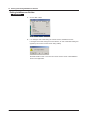
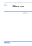
Starting AddObserver Builder
2
Procedure
Creating Monitor Screens with AddObserver Builder
Choose Start > Programs > YOKOGAWA DAQWORX > AddObserver > Builder.
AddObserver Builder starts.
3
4
Index
IM WX11-01E
2-1
2.1 Starting and Exiting AddObserver Builder
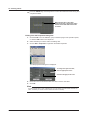
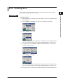
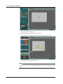
Exiting AddObserver Builder
Procedure
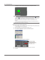
1. Choose File > Exit.
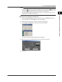
2. If no changes were made during the current session, AddObserver exits.
If changes were made during the current session, an exit confirmation dialog box
appears (one for each monitor screen being edited).
2-2
Click Yes or No to save or not save the current monitor screen. Click Cancel to
return to the application.
IM WX11-01E
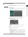
2.2
1
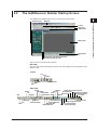
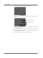
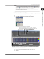
The AddObserver Builder Startup Screen
The AddObserver Builder startup screen is shown in the figure below.
Operation panel
2
Menu bar
Creating Monitor Screens with AddObserver Builder
Tool bar
Object bar
Attribute bar
3
4
Editing area
Arrangement
bar
Edit/channel page Show/Hide button
Edit/channel page spreader
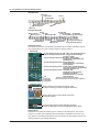
The functions of each item are as follows:
Menu Bar
The menu bar contains the following menus: File, Edit, Gadget, Text, Arrangement, View,
Window, Help.
Toolbar
Cut
Copy
Paste
New
Save
Open
About Builder
Object Bar
Edit
Ellipse
Arc
Polygon
Digital
Monitor
Temperature Controller Parts
Picture
Bar Meter
Selectable Out
Extended Trend Graph
Trend
Analog Meter
Numeric Out
Extended Indicator
Graph
Thermometer
Button
X-Y Graph
Indicator
Rectangle
Line
Value Rectangle
Label
IM WX11-01E
Alarm Summary
Thermometer Set
String
Change
Rectangle
Analog Meter Set
Color Change Ellipse
Bar Meter Set
Color Change Rectangle
Digital Meter Set
2-3
Index
2.2 The AddObserver Builder Startup Screen
Attribute Bar
Align Left
Align Center
Align Right
No Fill
Fill
Both Points Arrow
End Point Arrow
Start Point Arrow
No Arrow
Underline
Italic
Bold
Arrangement Bar
Group
Move to Front
Tab Page
Move Forward
Group Tab Pages
Arrange Top
Same Width
Center Vertically
Arrange Bottom Same Height
Unify Vertical Interval
Arrange Right
Move to Back Ungroup
Center Horizontally
Move Backward
Unify Horizontal Interval
Arrange Left
Operation Panel
The operation panel has an Edit page containing tools for creating and editing objects
and changing their color, and a Channel page for assigning alarms.
• Edit Page
1st row starting from the left: Edit, Label, Line, Rectangle, Ellipse
2nd row starting from the left: Arc, Polygon, Value Rectangle1
Indicator1, Digital1
3rd row starting from the left: Bar Meter1, Analog Meter1,
Thermometer1, Digital Meter Set1,
Bar Meter Set1
4th row starting from the left: Analog Meter Set1,
Thermometer Set1, Trend Graph1,
Picture, Monitor
5th row starting from the left: Button, Color Change Rectangle1,
Color Change Elipse1, String Change
Rectangle1, Numeric Out
6th row starting from the left: Selectable Out,
Temperature Controller Parts,
Extended Trend Graph1,
Extended Indicator1, X-Y Graph1
7th:
Alarm Summary
Fill Color
Line Color
Font Color
1
Channels can be assigned to this object.
(Channel alarm labels can be assigned to indicators.)
• Channel Page
Drag a channel to each meter, trend graph, value,
or ellipse rectangle you want to assign the channel to.
Drag an alarm label to each indicator you want to
assign the alarm to.
To remove the channel or alarm label from an object,
drag the CLEAR button from the CLEAR PLATE to the object.
Editing Area
Objects can be created and edited (moved, resized) in the editing area. The monitor
screens you create will be displayed almost identically in AddObserver Panel as how
they appear in the editing area (there may be certain parts of trend graphs which do not
display exactly per the entered attributes).
2-4
IM WX11-01E
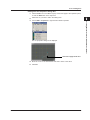
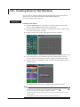
2.3
1
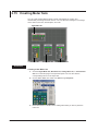
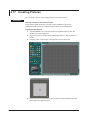
Creating New Monitor Screens
Procedure
2
1. Choose File > New, or click the New button on the toolbar.
Creating Monitor Screens with AddObserver Builder
3
4
New
Index
IM WX11-01E
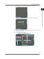
A new monitor screen appears.
2-5
2.4
Entering Host and Channel Settings
To display monitor screens (panels) using AddObserver Panel, host settings for
connecting to the DAQ32 Plus, DAQEXPLORER, DAQLOGGER, or MXLOGGER
monitor server, GateCONTROL and GateEye must first be entered in AddObserver
Builder.
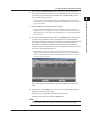
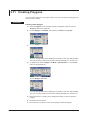
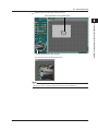
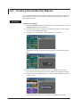
Procedure
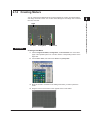
1. Choose Edit > Configuration.
The Configuration dialog box is displayed.
HOST tab
Add
Delete
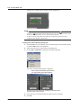
Entering Host Settings
2. Click the HOST tab. The host settings page appears.
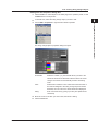
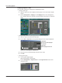
3. Click the Host Type box next to No. 0000, and set the host type to Input
Channel, I/O Channel, or V-Channel. When you connect the GateEye, you must
set the V-Channel.
4. Click the Host box. Enter the name of the computer1 that will host the monitor
server.
1 The name used to identify the computer on the network. You can also enter the IP
address.
5. Click the Port No. box. Enter the port number2 of the monitor server to which you
will connect.
2 The default value for the monitor server’s port numbers are 50278 for DAQ32 Plus,
50279 for DAQEXPLORER, 50280 for DAQLOGGER, 50284 for MXLOGGER, 50299
for GateCONTROL and 50290 for GateEye. Make sure you have the right port number,
especially if it may have been changed earlier. For instructions on how to check the port
number, consult the user’s manual for the monitor server you are using.
2-6
IM WX11-01E
2.4 Entering Host and Channel Settings
1
6. If you are using DAQEXPLORER as the monitor server, click the System No.
1
box then enter the system number set on the DAQEXPLORER. This setting is
unnecessary if your monitor server is DAQ32 Plus or DAQLOGGER, and the
value is fixed at 0 in those cases.
7. Click the Steps box and enter the number of steps2.
2 This value represents the length of data to be acquired at a time from the host. The
default value is 1, and a value from 1 to 120 can be entered. Enter 1 to have the all the
data acquired at once, 2 to acquire every other data point, 3 to acquire every third data
point, and so on.
8. To automatically download host information, click Get Info under Details. When
3
you click Get Info, Builder connects to the specified host and automatically
downloads information for the tag and color items on the Channel page (explained
on next page). The indicator changes to yellow when information is being
downloaded. It changes to blue when the downloading of the information is
complete. If you do not click Get Info, you can manually enter settings for the tag
and color on the Channel page later on.
3 To download information from the host (monitor server), the monitor server must be
started on the host computer. If after clicking Get Info the tag and color settings do not
appear or match those set on the host, check whether the monitor server is currently
running on the host computer.
Once these settings are downloaded, settings are complete for host number
0000.
9. To add a host, click the Add button. A new row for host number 0001 appears
below the row for host number 0000.
Follow steps 3–8 to enter the host settings for the new host.
To delete a host, select it then click the Delete button.
Note
• The maximum number of servers and hosts that can be set is 16 and 128 respectively.
• The host number is fixed within a range from 0000 to 0127 and cannot be changed.
IM WX11-01E
2-7
2
Creating Monitor Screens with AddObserver Builder
1 This is the same number that DAQ Desktop on the DAQEXPLORER assigns to the
DX100, DX200, MV100, or MV200’s mounted to it. The default value is 0. A value from 0
to 15 can be entered.
3
4
Index
2.4 Entering Host and Channel Settings
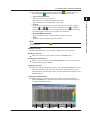
Entering Channel Settings
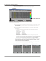
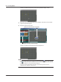
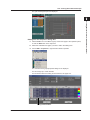
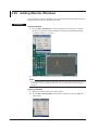
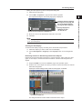
10.Click the CHANNEL tab. The channel settings page appears.
CHANNEL tab
Setting shortcut buttons.
For details, see page 2-10.
These are the numbers used for assigning channel or alarm labels to objects
such as meters and trend graphs.
11. Click the Host field for setting number 0000. Enter the host number (the number
from 0 to 0015 in the column under No. in the host page). A value from 0 to 15
can be entered.
12.Click the Channel1 field. Enter the channel on the host you wish to assign
something to.
1 A value of 0 corresponds to a different value on each monitor server as follows:
DAQ32 Plus: No. is 001
DAQEXPLORER: CH is CH1
DAQLOGGER: Tag No. is 1
MXLOGGER: Record is 0001
GateCONTROL:
Tag No. is TAG01
GateEye is set in the V-CHANNEL tab. 1 V channel is assigned to a single host.
For example, if you want to enter a setting corresponding to a No. setting on the DAQ32
Plus of 010, you must enter 9 for the channel setting on the AddObserver Builder.
2
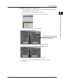
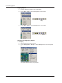
You can click the [ … ] button to display a table of channels when connecting to
the specified host (monitor server). To enter a channel from this table, click the
desired channel and then click the OK button.
2 You can choose to view the channel numbers, tag numbers, or tag comments in the
channel table. The number of channels that can be set is 1600.
Channel Number View
2-8
Tag Number View
Tag Comment View
IM WX11-01E
2.4 Entering Host and Channel Settings
1
13.To manually input the tag and color settings, click
arrow changes to
in the Att. column. The
, and the tag and color settings can be entered.
• Tag and Tag Comment
2
• Format
3
Enter the format type and decimal place. Click the icon on the left to toggle
between
and
.
is a fixed-point representation, and
is a floatingpoint representation. The value on the right determines how many places past
the decimal point are shown. Up to 6 places can be selected.
• Minimum/Maximum/Units
Enter the maximum value, minimum value, and units for the span.
• Color
Note
after entering user settings, all previously entered
Adding a Channel
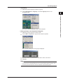
14.Click the Insert button. A new channel is added to the bottom of the list.
Deleting a Channel
14.Select the channel you wish to delete, and click the Delete button.
Deleting Unused Channels
14.Select a range of channels. Click the Del Unused button. All unused channels in
the selected range will be deleted.
Copying a Channel
14.Select the channel or channels you wish to copy and click the Copy button. Then
select the channel onto which you wish to paste the copied channel, and click
the Paste button. The setting information from the copied channel appears in the
selected channel.
Loading the Default Values
14.Select the range of channels into which you wish to load the default values.
Click the Default button. The settings for all channels in the selected range are
changed to their default values.
Inset
IM WX11-01E
Delete
Del Unused
Copy
4
Index
Enter the colors for the trend graph and zone bar.
Be aware that If you switch back to
settings will be lost.
Creating Monitor Screens with AddObserver Builder
Enter the tag name or tag comment.
Tag numbers of up to eitht characters can be input.
Tag comments of up to 32 characters can be input.
Paste
Default
2-9
2.4 Entering Host and Channel Settings
Note
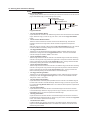
Setting Shortcut Buttons
The gray setting shortcut buttons are located just under the last channel row on the channel
page. These buttons help you enter settings more quickly.
Fill Tag Comments
Toggle Format Type
Copy Decimal Point
Fill Tag Numbers
Toggle Attribute
Fill Channel Numbers
Copy Host Number
Default Color
Copy Units
Copy Value
Copy Value
• The Copy Host Number Button
Copies the first host number in the selected range to the rest of the channels in the selected
range. Select the range you want to copy from and to, and click the Copy Host Number
button.
• The Fill Channel Numbers Button
Takes the channel number from the first channel in the selected range, and fills each
remaining channel in the range with a channel number one higher than the previous
channel.
Select the range of channels to fill and click the Fill Channel Numbers button. The channel
numbers are filled incrementally starting with the first channel in the selected range.
• The Toggle Attribute Button
Toggles the icon for all selected channels between ORIG and USER. Select the range
of channels to change and click the Toggle Attribute button. The icons of all selected
channels change from ORIG to USER or vice versa.
• The Fill Tag Numbers Button
Takes the tag number from the first channel in the selected range, and fills each remaining
channel in the range with a tag number one higher than in the previous channel. Select the
range of channels to fill and click the Fill Tag Numbers button. The tag numbers are filled
incrementally starting with the first channel in the selected range.
• The Fill Tag Comments Button
Takes the tag comment from the first channel in the selected range, and fills each remaining
channel in the range with a tag comment one higher than the previous channel. Select the
range of channels to fill and click the Fill Tag Comments button. The tag comments are
filled incrementally starting with the first channel in the selected range.
• The Toggle Format Type Button
Toggles the icon for all selected channels between F and E. Select the range of channels
to change and click the Toggle Format Type button. The icons of all selected channels
change from F to E or vice versa.
• The Copy Decimal Point Button
Copies the number of decimal places specified in the first channel in the selected range to
the rest of the channels in the selected range. Select the range you want to copy from and
to, and click the Copy Decimal Point button. The number of decimal places is copied to the
selected range.
• The Copy Value Buttons
Copies the value from the first channel in the selected range to the rest of the channels
in the selected range. Select the range you want to copy to and from, and click one of the
Copy Value buttons. The value is copied to the selected range.
• The Copy Units Button
Copies the value from the first channel in the selected range to the rest of the channels in
the selected range. Select the range you want to copy from and to, and click the Copy Units
button. The units are copied to the entire range.
• The Default Color Button
Loads the default color values for all channels in the selected range. Select the desired
range and click the Default Color button. The default color values for all channels in the
selected range are loaded.
2-10
IM WX11-01E
2.4 Entering Host and Channel Settings
1
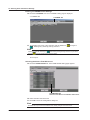
Output Channel Detail Settings
10.Click the Output Channel tab. The output channel setup page appears. An output
channel can only be added when the host type in the host detail settings is I/O
Channel.
OUTPUT CHANNEL tab
2
Creating Monitor Screens with AddObserver Builder
3
4
Index
11. Output channels can only be assigned to output channel objects. Specify and
register the host names and channel numbers. Set the tag, tag comment, decimal
place (format), output maximum, output minimum, and units for each channel.
The maximum number of hosts that can be set is 1600.
For details on settings, see prcodures 12 through 14 under “Channel Detail
Settings.”
Controller Detail Settings
10.Click the Controller tab. The controller setup page appears. A controller can only
be added when the host type in the detail settings is I/O Channel, and the I/O
Channel host information is successfully acquired.
CONTROLLER tab
IM WX11-01E
If controller related channels or output channels are deleted or changed through
channel tags or output channel tags, the controllers are also deleted at the same
time.
The maximum number of controllers that can be registered is 128.
2-11
2.4 Entering Host and Channel Settings
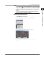
Entering V-CHANNEL Detail Settings
10.Click the V-CHANNEL tab. The V-CHANNEL setting page is displayed.
V-CHANNEL tab
V-CHANNEL tab
11. To manually enter a tag or tag comment, click the Detail box.
changes to
, allowing entry of the tag and tag comment.
Note
Please note that after switching to
back to
and entering the tag and tag comment, if you switch
, the item reverts to the previous setting.
Go to step 15.
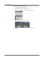
Selecting the Alarms That Will Sound
15.Click the ALARM SOUND tab. The ALARM SOUND setting page appears.
ALARM SOUND tab
Sound an alarm when a red indication alarm occurs
16.Select the alarm that will sound.
17.Click OK to close the Configuration dialog box.
Note
Be aware that if you click Cancel instead of OK, setting changes will not be saved.
2-12
IM WX11-01E
2.5
1
Protection for Out Object
2
Creating Monitor Screens with AddObserver Builder
With AddObserver, people who can use the Builder software are given the same
privileges as the administrator. When the user name, password, and protection level are
entered, only the out objects that are at or below the protection level can be output.
3
Procedure
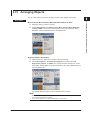
1. From the Edit menu, choose User Settings.
4
Index
The user settings dialog box is displayed.
2. Input the user name and password and select a protection level.
IM WX11-01E
Up to sixteen alphanumeric characters can be input for the user name and
password.
A protection level of 1, 2, or 3 can be selected. The larger the protection level
number the higher the level of protection, and only the out objects at or below that
protection level can be output.
The number of users that can be set is sixteen.
The same name cannot be assigned to more than one user.
You must enter a user name.
2-13
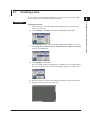
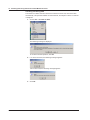
2.6
Creating Labels
You can enter a character string of your choice to create a label. You can also select the
size, style, color, and fill for the text.
Procedure
Creating a New Label
1. Click the Label icon on the EDIT page of the operation panel, or click the Label
button in the object bar.
2. Choose Text > Style, then Bold, Italic, or Underline. You can also click the Bold,
Italic, or Underline buttons on the attribute bar. You can also select, Bold and
Italic at the same time.
3. Choose Text > Size, then select from Auto through 96 points.
4. Choose Text > Align, then select Left, Center, or Right. You can also click the
Left, Center, or Right buttons on the attribute bar.
5. Choose Text > Color.
2-14
The color settings dialog box is displayed. For details on the color settings dialog
box, see “Choosing a Color from the Color Settings Dialog Box” in section 2.30.
IM WX11-01E
2.6 Creating Labels
6. To apply the fill, choose Gadget > Fill Mode > Selected Color, or click the Fill
1
button on the attribute bar.
2
Creating Monitor Screens with AddObserver Builder
3
Choose Gadget > Fill Color.
4
Index
The color settings dialog box is displayed. For details on the color settings dialog
box, see “Choosing a Color from the Color Settings Dialog Box” in section 2.30.
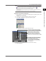
7. Move the mouse to a location in the editing area where you want to place the
upper-left corner of the label.
8. Drag the cursor to set the location of the opposite corner of the label.
9. The cursor blinks inside the new label, allowing you to enter a character string.
The character string you enter will appear within the frame of the label.
IM WX11-01E
2-15
2.6 Creating Labels
10.Press the ENTER key on the keyboard to confirm the entered character string and
complete the label.
When the text size is set to Auto,
the text contracts or expands to match
the size of the label frame if the frame
is resized.
Editing from the Properties Dialog Box
1. Click the Edit icon in the OBJECT group of the EDIT page of the operation panel,
or click the Edit button in the object bar.
2. Select the label you wish to edit in the editing area.
3. Choose Edit > Properties or right-click and select Properties.
The label properties dialog box is displayed.
To change the style of the text,
click the appropriate icons.
Click here to apply the fill color.
4. Move the cursor to the desired item and click to enter a new value.
5. Click OK.
Note
If a label overlaps with a meter, AddObserver Panel will display the label hidden beneath the
meter. Therefore you should not allow labels and meters to overlap.
2-16
IM WX11-01E
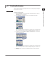
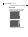
2.7
1
Creating Lines
You can create a line of any length and direction. You can also specify the line’s width,
color, and whether arrowheads are attached to the ends.
Creating a New Line
3
1. Click the Line icon on the EDIT page of the operation panel, or click the Line
button in the object bar.
2. Choose Gadget > Line Width, then select from 0 dots through 5 dots.
4
Index
3. Choose Gadget > Arrow, then choose None, Start, End, or Both. You can also
click the No Arrow, Start Point Arrow, End Point Arrow, or Both Points Arrow
buttons on the attribute bar.
4. Choose Gadget > Line Color.
The color settings dialog box is displayed. For details on the color settings dialog
box, see “Choosing a Color from the Color Settings Dialog Box” in section 2.30.
5. Move the mouse to a location in the editing area where you want to start the line.
6. Drag the mouse to the end point of the line.
IM WX11-01E
Creating Monitor Screens with AddObserver Builder
Procedure
2
2-17
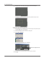
2.7 Creating Lines
A line is created between the start and end points you specified.
Editing from the Properties Dialog Box
1. Click the Edit icon in the OBJECT group of the EDIT page of the operation panel,
or click the Edit button in the object bar.
2. Select the line you wish to edit in the editing area.
3. Choose Edit > Properties or right-click and select Properties.
The line properties dialog box is displayed.
4. Move the cursor to the desired item and click to enter a new value.
5. Click OK.
2-18
IM WX11-01E
2.8
1
Creating Rectangles
You can create a rectangle of any shape and size. You can also specify the rectangle’s
line width, line color, and fill.
Creating a New Rectangle
1. Click the Rectangle icon on the EDIT page of the operation panel, or click the
Rectangle button in the object bar.
2. Choose Gadget > Line Width, then select from 0 dots through 5 dots.
Index
3. Choose Gadget > Line Color.
The color settings dialog box is displayed. For details on the color settings dialog
box, see “Choosing a Color from the Color Settings Dialog Box” in section 2.30.
4. To apply the fill, choose Gadget > Fill Mode > Selected Color, or click the Fill
button on the attribute bar.
Choose Gadget > Fill Color.
The color settings dialog box is displayed. For details on the color settings dialog
box, see “Choosing a Color from the Color Settings Dialog Box” in section 2.30.
5. Move the mouse to a location in the editing area where you want to place the
rectangle.
IM WX11-01E
3
4
Creating Monitor Screens with AddObserver Builder
Procedure
2
2-19
2.8 Creating Rectangles
6. Drag the cursor to the location of the opposite corner of the rectangle.
A rectangle is created using the two corner points specified in steps 5 and 6.
Editing from the Properties Dialog Box
1. Click the Edit icon in the OBJECT group of the EDIT page of the operation panel,
or click the Edit button in the object bar.
2. Select the rectangle you wish to edit in the editing area.
3. Choose Edit > Properties.
The rectangle properties dialog box is displayed.
Click here to apply the fill color.
4. Move the cursor to the desired item and click to enter a new value.
5. Click OK.
2-20
IM WX11-01E
2.9
1
Creating Ellipses
You can create an ellipse of any shape and size. You can also specify the ellipse’s line
width, line color, and fill.
Creating a New Ellipse
1. Click the Ellipse icon on the EDIT page of the operation panel, or click the Ellipse
button in the object bar.
2. Choose Gadget > Line Width, then select from 0 dots through 5 dots.
Index
3. Choose Gadget > Line Color.
The color settings dialog box is displayed. For details on the color settings dialog
box, see “Choosing a Color from the Color Settings Dialog Box” in section 2.30.
4. To apply the fill, choose Gadget > Fill Mode > Selected Color, or click the Fill
button on the attribute bar.
Choose Gadget > Fill Color.
The color settings dialog box is displayed. For details on the color settings dialog
box, see “Choosing a Color from the Color Settings Dialog Box” in section 2.30.
5. Move the mouse to a location in the editing area where you want to place the
ellipse.
IM WX11-01E
3
4
Creating Monitor Screens with AddObserver Builder
Procedure
2
2-21
2.9 Creating Ellipses
6. Drag the cursor to the location of the opposite end of the ellipse.
An ellipse is created using a frame based on the two corner points specified in
steps 5 and 6.
Editing from the Properties Dialog Box
1. Click the Edit icon in the OBJECT group of the EDIT page of the operation panel,
or click the Edit button in the object bar.
2. Select the ellipse you wish to edit in the editing area.
3. Choose Edit > Properties or right-click and select Properties.
The ellipse properties dialog box is displayed.
Click here to apply the fill color.
4. Move the cursor to the desired item and click to enter a new value.
5. Click OK.
2-22
IM WX11-01E
1
2.10 Creating Arcs
You can create an arc of any shape or size. You can also specify the arc’s line width,
starting angle, ending angle, line color, and fill.
2
Creating a New Arc
1. Click the Arc icon on the EDIT page of the operation panel, or click the Arc button
in the object bar.
2. Choose Gadget > Line Width, then select from 0 dots through 5 dots.
Index
3. Choose Gadget > Line Color.
The color settings dialog box is displayed. For details on the color settings dialog
box, see “Choosing a Color from the Color Settings Dialog Box” in section 2.30.
4. To apply the fill, choose Gadget > Fill Mode > Selected Color, or click the Fill
button on the attribute bar.
Choose Gadget > Fill Color.
The color settings dialog box is displayed. For details on the color settings dialog
box, see “Choosing a Color from the Color Settings Dialog Box” in section 2.30.
5. Move the mouse to a location in the editing area where you want to place the arc.
IM WX11-01E
3
4
Creating Monitor Screens with AddObserver Builder
Procedure
2-23
2.10 Creating Arcs
6. Drag the cursor to the location of the opposite end of the arc.
An arc is created using a frame based on the two corner points specified in steps
5 and 6.
Anchor points (yellow frame)
Anchor points (blue frame)
7. To change the arc’s length, click the arc to select it (usually items are selected as
soon as they are created).
8. Move the cursor over one of the blue anchor points at the start or end of the arc.
9. Drag the anchor point to a new position (you may only move the anchor point to a
new position along the arc itself).
10.The other anchor point can also be moved in the same manner.
2-24
IM WX11-01E
2.10 Creating Arcs
1
Editing from the Properties Dialog Box
1. Click the Edit icon in the OBJECT group of the EDIT page of the operation panel,
or click the Edit button in the object bar.
2
2. Select the arc you wish to edit in the editing area.
3. Choose Edit > Properties or right-click and select Properties.
Creating Monitor Screens with AddObserver Builder
3
4
Index
The arc properties dialog box is displayed.
Click here to apply the fill color.
4. Move the cursor to the desired item and click to enter a new value.
5. Click OK.
IM WX11-01E
2-25
2.11 Creating Polygons
You can create a polygon of any shape and size. You can also specify the polygon’s line
width, line color, and fill.
Procedure
Creating a New Polygon
1. Click the Polygon icon on the EDIT page of the operation panel, or click the
Polygon button in the object bar.
2. Choose Gadget > Line Width, then select from 0 dots through 5 dots.
3. Choose Gadget > Line Color.
The color settings dialog box is displayed. For details on the color settings dialog
box, see “Choosing a Color from the Color Settings Dialog Box” in section 2.30.
4. To apply the fill, choose Gadget > Fill Mode > Selected Color, or click the Fill
button on the attribute bar.
Choose Gadget > Fill Color.
The color settings dialog box is displayed. For details on the color settings dialog
box, see “Choosing a Color from the Color Settings Dialog Box” in section 2.30.
5. Move the mouse to a location in the editing area where you want to place the
polygon.
6. Click the left mouse button.
7. Move the cursor to the next vertex on the polygon and left-click again.
2-26
IM WX11-01E
2.11 Creating Polygons
1
8. Repeat step 7 until all sides of the polygon are completed.
2
Creating Monitor Screens with AddObserver Builder
3
4
9. To finish the polygon, double click the mouse.
Index
The created polygon and its anchor
points are displayed.
You can reshape the polygon by
dragging its (blue) anchor points.
Editing from the Properties Dialog Box
1. Click the Edit icon in the OBJECT group of the EDIT page of the operation panel,
or click the Edit button in the object bar.
2. Select the polygon you wish to edit in the editing area.
3. Choose Edit > Properties or right-click and select Properties.
The polygon properties dialog box is displayed.
Click the Points tab
To delete an angle, select the angle's
number and click the Delete button.
Click here to apply the fill color.
To add an angle, select the angle whose number is
one higher than the one you want to add.
Click the Insert button, then input the X and Y
coordinates of the new vertex.
4. Move the cursor to the desired item and click to enter a new value.
5. Click OK.
IM WX11-01E
2-27
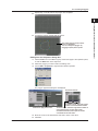
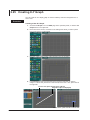
2.12 Creating Value Rectangles
You can create a value rectangle for any channel. You can also specify the value
rectangle’s line width and line color.
Procedure
Creating a New Value Rectangle
1. Click the Value Rectangle icon in the OBJECT group of the EDIT page of the
operation panel, or click the Value Rectangle button in the object bar.
2. Choose Gadget > Line Width, then select from 0 dots through 5 dots.
3. Choose Gadget > Line Color.
The color settings dialog box is displayed. For details on the color settings dialog
box, see “Choosing a Color from the Color Settings Dialog Box” in section 2.30.
4. Choose Gadget > Fill Color.
The color settings dialog box is displayed. For details on the color settings dialog
box, see “Choosing a Color from the Color Settings Dialog Box” in section 2.30.
5. Move the mouse to a location in the editing area where you want to place the
value rectangle.
6. Drag the cursor to the location of the opposite corner of the value rectangle.
2-28
IM WX11-01E
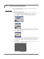
2.12 Creating Value Rectangles
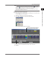
A value rectangle is created using the two corner points specified in steps 5 and 6.
1
2
Creating Monitor Screens with AddObserver Builder
3
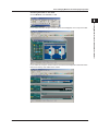
7. Move the cursor to the channel you wish to assign to the value rectangle on the
channel page of the operation panel.
8. Drag the channel to the value rectangle.
Index
(2) Drop the channel plate on the value rectangle.
(1) Drag the channel you wish to assign.
A value rectangle is created with the desired channel assigned to it.
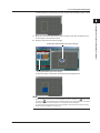
Note
• When you drag a channel over a value rectangle, the cursor changes to a
. If the cursor
changes to a
, this indicates that the selected channel can not be assigned to the value
rectangle. Be sure to confirm whether or not a channel may be assigned.
• To remove channel assignments from value rectangles, see “Removing Channel or Alarm
Assignments from Objects” in section 2.30.
IM WX11-01E
4
2-29
2.12 Creating Value Rectangles
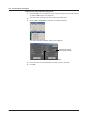
Editing from the Properties Dialog Box
1. Click the Edit icon in the OBJECT group of the EDIT page of the operation panel,
or click the Edit button in the object bar.
2. Select the value rectangle you wish to edit in the editing area.
3. Choose Edit > Properties or right-click and select Properties.
The value rectangle properties dialog box is displayed.
Click here to change
the assigned channel.
Click here to edit the maximum and minimum values.
4. Move the cursor to the desired item and click to enter a new value.
5. Click OK.
2-30
IM WX11-01E
1
2.13 Creating Indicators
You can create an indicator for any channel’s alarm. You can also create channel or
alarm labels.
2
Creating Monitor Screens with AddObserver Builder
Procedure
Creating a New Indicator
3
1. Click the Indicator icon on the EDIT page of the operation panel, or click the
Indicator button in the object bar.
2. Move the mouse to a location in the editing area where you want to place the
4
indicator.
3. Drag the cursor to the location of the opposite end of the indicator.
Index
An indicator is created using the two corner points specified in steps 2 and 3.
4. Move the cursor to the channel alarm you wish to assign to the indicator on the
channel page of the operation panel.
5. Drag the alarm to the indicator created in step 3.
(2) Drop the channel alarm plate on the indicator.
(1) Drag the channel alarm you wish to assign.
IM WX11-01E
2-31
2.13 Creating Indicators
An indicator to which the desired channel alarm is assigned is created.
Note
• When you drag a channel alarm over an indicator, the cursor changes to a
. If the cursor
changes to a
, this indicates that the selected channel alarm can not be assigned to the
indicator. Be sure to confirm whether or not a channel may be assigned.
• Only channel alarm labels can be assigned to indicators. A channel itself cannot be
assigned.
• To remove channel alarm label assignments from indicators, see “Removing Channel or
Alarm Assignments from Objects” in section 2.30.
Editing from the Properties Dialog Box
1. Click the Edit icon in the OBJECT group of the EDIT page of the operation panel,
or click the Edit button in the object bar.
2. Select the indicator you wish to edit in the editing area.
3. Choose Edit > Properties or right-click and select Properties.
The indicator properties dialog box is displayed.
Click here to change
the assigned channel.
To change the alarm label,
select from L1 to L4.
4. Move the cursor to the desired item and click to enter a new value.
5. Click OK.
2-32
IM WX11-01E
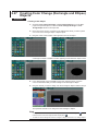
1
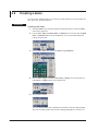
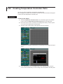
2.14 Creating Meters
Digital
2
Creating Monitor Screens with AddObserver Builder
You can create several different kinds of meters (digital, bar, analog, and thermometer)
and assign channels to them. You can also enter settings for such things as the channel,
text size, and units.
3
4
Index
Bar Meter
Analog Meter
Thermometer
Procedure
Creating a New Meter
1. Click the Digital, Bar Meter, Analog Meter, or Thermometer icon on the EDIT
page of the operation panel. You can also click the corresponding buttons on the
object bar.
2. Choose Text > Size, then select from Auto through 96 points.
3. Move the mouse to a location in the editing area where you want to place the
meter.
4. Drag the cursor to the location of the opposite corner of the meter.
IM WX11-01E
2-33
2.14 Creating Meters
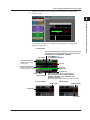
A meter is created using the two corner points specified in steps 3 and 4.
5. Move the cursor to the channel you wish to assign to the meter on the channel
page of the operation panel.
6. Drag the channel to the meter.
(2) Drop the channel plate on the meter.
(1) Drag the channel you wish to assign.
A meter is created with the desired channel assigned to it.
Note
• When you drag a channel over a meter, the cursor changes to a
. If the cursor changes
to a
, this indicates that the selected channel can not be assigned to the meter. Be sure
to confirm whether or not a channel may be assigned.
• To remove channel assignments from meters, see “Removing Channel or Alarm
Assignments from Objects” in section 2.30.
2-34
IM WX11-01E
2.14 Creating Meters
1
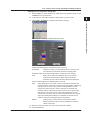
Editing from the Properties Dialog Box
1. Click the Edit icon in the OBJECT group of the EDIT page of the operation panel,
or click the Edit button in the object bar.
2
2. Select the meter you wish to edit in the editing area.
3. Choose Edit > Properties or right-click and select Properties.
Creating Monitor Screens with AddObserver Builder
3
4
Index
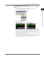
The meter properties dialog box is displayed.
The digital meter properties dialog box
F Type (fixed decimal representation)
E Type (floating point representation)
T Type (Time represetation)
Click here to edit the values for the format, decimal point, and units.
The bar meter, analog meter, and thermometer properties dialog box
Click here to edit the maximum, minimum, and units values.
4. Move the cursor to the desired item and click to enter a new value.
5. Click OK.
IM WX11-01E
2-35
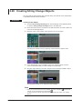
2.15 Creating Meter Sets
You can create several different kinds of meter sets (digital, bar, analog, and
thermometer) and assign channels to them. You can also enter settings for such things
as the channel, text size, decimal place, and units.
Digital Meter Set
Bar Meter Set
Analog Meter Set
Thermometer Set
Procedure
Creating a New Meter Set
1. Click the Digital Meter Set, Bar Meter Set, Analog Meter Set, or Thermometer
Set icon on the EDIT page of the operation panel. You can also click the
corresponding buttons on the object bar.
2. Choose Text > Size, then select from Auto through 96 points.
3. Move the mouse to a location in the editing area where you want to place the
meter set.
2-36
IM WX11-01E
2.15 Creating Meter Sets
1
4. Drag the cursor to the location of the opposite corner of the meter set.
2
Creating Monitor Screens with AddObserver Builder
3
4
A meter set is created using the two corner points specified in steps 3 and 4.
Index
5. Move the cursor to the channel you wish to assign to the meter set on the channel
page of the operation panel.
6. Drag the channel to the meter set.
(2) Drop the channel plate on the meter set.
(1) Drag the channel you wish to assign.
IM WX11-01E
2-37
2.15 Creating Meter Sets
A meter set is created with the desired channel assigned to it.
Note
• When you drag a channel over a meter set, the cursor changes to a
. If the cursor
changes to a
, this indicates that the selected channel can not be assigned to the meter
set. Be sure to confirm whether or not a channel may be assigned.
• To remove channel assignments from meter sets, see “Removing Channel or Alarm
Assignments from Objects” in section 2.30.
Editing from the Properties Dialog Box
1. Click the Edit icon in the OBJECT group of the EDIT page of the operation panel,
or click the Edit button in the object bar.
2. Select the meter set you wish to edit in the editing area.
3. Choose Edit > Properties or right-click and select Properties.
The meter set properties dialog box is displayed.
Select F Type (fixed decimal representation)
or E Type (floating point representation).
Click here to edit the format type, decimal point, minimum value,
maximum value, units, and color.
4. Move the cursor to the desired item and click to enter a new value.
5. Click OK.
2-38
IM WX11-01E
1
2.16 Creating Trend Graphs
You can create trend graphs and assign channels to them. You can also enter settings
for such things as the channel, units, grid color, and background color.
2
Creating Monitor Screens with AddObserver Builder
Procedure
Creating a New Trend Graph
3
1. Click the Trend Graph icon in the OBJECT group of the EDIT page of the
operation panel, or click the Trend Graph button in the object bar.
2. Move the mouse to a location in the editing area where you want to place the
4
trend graph.
3. Drag the cursor to the location of the opposite corner of the trend graph.
Index
A trend graph is created using the two corner points specified in steps 2 and 3.
4. Move the cursor to the channel you wish to assign to the trend graph on the
channel page of the operation panel.
IM WX11-01E
2-39
2.16 Creating Trend Graphs
5. Drag the channel to the trend graph.
(2) Drop the channel plate on the trend graph.
(1) Drag the channel you wish to assign.
The specified channel is assigned to the trend graph.
6. Repeat steps 4 and 5 for each channel you wish to assign.
A trend graph is created with the desired channel assigned to it.
2-40
IM WX11-01E
2.16 Creating Trend Graphs
1
Note
• When you drag a channel over a trend graph, the cursor changes to a
. If the cursor
, this indicates that the selected channel can not be assigned to the trend
changes to a
graph. Be sure to confirm whether or not a channel may be assigned.
• To remove channel assignments from trend graphs, see “Removing Channel or Alarm
Assignments from Objects” in section 2.30.
1. Click the Edit icon in the OBJECT group of the EDIT page of the operation panel,
or click the Edit button in the object bar.
2. Select the trend graph you wish to edit in the editing area.
Creating Monitor Screens with AddObserver Builder
Editing from the Properties Dialog Box
2
3
4
3. Choose Edit > Properties or right-click and select Properties.
Index
The meter set properties dialog box is displayed.
Select one of the following zones for the y-axis: User Zone,
Full Zone, Slide Zone, Multi-Axes Zone, Edit Zone, or Auto Zone.
Click here to apply display limits.
Select a grid type.
Click here to display alarms.
Setting shortcut buttons (see page 2-10).
Each trend graph setting is the same as for the DAQ32 Plus, DAQEXPLORER, DAQLOGGER, or
MXLOGGER.
For details, see their respective user’s manuals.
4. Move the cursor to the desired item and click to enter a new value.
5. Click OK.
IM WX11-01E
2-41
2.17 Creating Pictures
You can place a “picture” (a bit mapped image) in the monitor screen.
Procedure
Placing a Picture in the Picture Folder
Place images in BMP format that you want to have available for use into the
AddObserver/Picture directory created during installation of the AddObserver.
Creating a New Picture
1. Click the Picture icon on the EDIT page of the operation panel, or click the
Picture button in the object bar.
2. Move the mouse to a location in the editing area where you want to place the
picture.
3. Drag the cursor to the location of the opposite corner of the picture.
A picture frame is created using the two corner points specified in steps 2 and 3.
4. Move the cursor to the picture you want to place in the PICTURE group on the
EDIT page of the operation panel.
2-42
IM WX11-01E
2.17 Creating Pictures
1
5. Drag the picture to the frame created in step 3.
(2) Drop the picture on the picture frame.
2
Creating Monitor Screens with AddObserver Builder
3
4
Index
(1) Drag the picture you wish to place.
The selected picture fills the picture frame.
Note
You can still drag a picture onto the editing area even if you do not first create a frame for it. In
this case, the picture is sized according to the original size of the BMP file.
IM WX11-01E
2-43
2.17 Creating Pictures
Editing from the Properties Dialog Box
1. Click the Edit icon in the OBJECT group of the EDIT page of the operation panel,
or click the Edit button in the object bar.
2. Select the picture you wish to edit in the editing area.
3. Choose Edit > Properties or right-click and select Properties.
The picture properties dialog box is displayed.
4. Move the cursor to the desired item and click to enter a new value.
5. Click OK.
2-44
IM WX11-01E
1
2.18 Creating Monitor Windows
You can arrange GateEye images.
2
Procedure
2. Select the Edit tab in the operation panel. Click the Monitor icon under Objects, or
the Monitor button on the object bar.
Creating Monitor Screens with AddObserver Builder
1. Enter detailed channel settings (see section 2.4).
3
4
Index
3. On the editing screen, move the mouse to one corner of the area where you want
to place the monitor.
4. Drag the mouse to the corner opposite the point specified in step 3.
IM WX11-01E
A rectangular monitor frame appears based on the 2 opposing points specified in
steps 3 and 4.
2-45
2.18 Creating Monitor Windows
5. Select the Channel tab in the operation panel. Move the mouse to the monitor you
wish to place under V-Channel.
6. Drag the monitor into the frame created in step 4.
The specified monitor and V channel number are displayed in the frame.
7. Choose File > Save or Save As to save.
Note
To view the monitor window, open AddObserver panel.
For details, see section 2.1–2.2 of the WX83 AddObserver Runtime User’s Manual (IM WX8301E).
2-46
IM WX11-01E
1
2.19 Creating Buttons
You can create buttons for various tasks such as stopping alarm sounds and showing or
hiding a specified monitor window.
Creating a New Button
1. Click the Button icon on the EDIT page of the operation panel, or click the Button
button in the object bar.
2. Move the mouse to a location in the editing area where you want to place the
Creating Monitor Screens with AddObserver Builder
Procedure
2
3
4
button.
Index
3. Drag the cursor to the location of the opposite corner of the button.
A button is created using the two corner points specified in steps 2 and 3.
Setting the Button Function, Button Name, and Display Type
4. Choose Edit > Properties.
The button properties dialog box is displayed.
Display Type
5. Select black text on white background or black text on white background.
Font Size
6. Select the size of the text that will appear on the buttons.
Label
7. Enter the text that will appear on the button.
Function
8. Select the function to be performed when the button is pressed from None, Hide,
Show, Alarm Sound ACK.
9. If you select Show or Hide, select the monitor window to be shown or hidden. To
IM WX11-01E
select a monitor window, monitor windows must be added beforehand. For details,
see the next page.
You can specify the monitor window by dragging and dropping the icon of the
desired window tab onto the button. In this case, the function automatically
changes to Hide.
2-47
2.20 Creating Numeric Out Windows
You can create an object for editing output values and sending them to hosts whose
types are set to I/O Channel in the Channel Detail Setting dialog box.
You can only assign output channels.
Procedure
Creating a New Object
1. Click the Numeric Out icon under Objects in the EDIT page of the operation
panel, or click the Numeric Out button in the object bar.
2. Move the mouse cursor to a location in the editing area where you want to place
one corner of the numeric out object.
3. Drag the cursor to the location of the opposite corner of the object.
A numeric out object is created in the two opposing corners defined in steps 2 and 3.
4. In the Setting Plate of the CHANNEL page in the operation panel, move the
cursor to the output channel that you wish to assign to the numeric out object.
5. Drag the OUTPUT CHANNNEL you wish to assign over the numeric out object
created in step 3.
The specified output channel is now assigned to the numeric out object.
Note
• When you move the output channel over the numeric out object, the cursor changes to
.
Note that the output channel cannot be assigned when displayed as
.
• You can only assign output channels to numeric out objects.
• To delete the output channel assignment from the numeric out object, see section 2.30,
“Editing Objects.”
• If no channels are linked to the output channel, it cannot be assigned.
2-48
IM WX11-01E
2.20 Creating Numeric Out Windows
1
Editing from the Properties Dialog Box
1. Click the Edit icon under Objects in the EDIT page of the operation panel, or click
the Edit button in the object bar.
2
2. In the Edit area, select the numeric out object you wish to edit.
3. Choose Edit > Properties or right-click and select Properties.
Creating Monitor Screens with AddObserver Builder
3
4
Index
The numeric out object’s properties dialog box opens.
When OFF, outputs from the dialog box.
When ON, the edit box is displayed in the
objects area, and the edited values are output.
Character string to display before the output value
Select this check box (light blue) to enable the
decimal point, minimum, maximum, and unit settings.
Set the lower and upper limits that can be sent.
When the value exceeds this range it cannot be
sent, but it can be displayed.
Click here to change the output channel to
be registered. An Output Channel dialog box
opens. Select the channel.
4. Move the cursor to the item you wish to edit, then enter a setting.
5. Click the OK button.
IM WX11-01E
2-49
2.21 Creating Selectable Out Objects
You can create an object that lets you select a character string to which an output value
was registered, and send it to a host whose type is set to I/O Channel in the Channel
Detail Setting dialog box.
Procedure
Creating a New Object
1. Click the Selectable Out icon in the EDIT page of the operation panel, or click the
Selectable Out button in the object bar.
2. Move the mouse cursor to a location in the editing area where you want to place
one corner of the selectable out object.
3. Drag the cursor to the location of the opposite corner of the object.
A selectable out object is created in the two opposing corners defined in steps 2
and 3.
4. In the Setting Plate of the CHANNEL page in the operation panel, move the
cursor to the output channel that you wish to assign to the selectable out object.
5. Drag the OUTPUT CHANNEL you wish to assign over the selectable out object
created in step 3.
2-50
The specified output channel is now assigned to the selectable out object.
IM WX11-01E
2.21 Creating Selectable Out Objects
Note
• When you move the output channel over the selectable out object, the cursor changes to
2
Creating Monitor Screens with AddObserver Builder
. Note that the output channel cannot be assigned when displayed as
.
• You can only assign output channels to selectable out objects.
• To delete the output channel assignment from the selectable out object, see section 2.30,
“Editing Objects.”
• If no channels are linked to the output channel, it cannot be assigned.
1
3
Editing from the Properties Dialog Box
1. Click the Edit icon under Objects in the EDIT page of the operation panel, or click
the Edit button in the object bar.
4
2. In the Edit area, select the selectable out object you wish to edit.
3. Choose Edit > Properties or right-click and select Properties.
Index
The selectable out object’s properties dialog box opens.
The range of values that can be specified
is 0 to 99. Click here to change the output
channel to be registered. An Output Channel
dialog box opens. Select the channel.
When OFF, outputs from the dialog box.
When ON, the edit box is displayed in the
objects area, and the edited values are output.
The integer values and character strings to
be displayed are shown on a spreadsheet.
You can edit the character string.
Up to 16 characters can be entered for
the character string. Up to eight statuses
can be registered.
4. Move the cursor to the item you wish to edit, then enter a setting.
5. Click the OK button.
IM WX11-01E
2-51
2.22 Creating Temperature Controller Parts
You can only assign controllers to temperature controller parts.
When assigning a controller, the controller’s channels and output channels are assigned
to each part of the temperature controller parts.
Procedure
Creating a New Object
1. Click the Temperature Controller Parts icon in the EDIT page of the operation
panel, or click the Temperature Controller Parts button in the object bar.
2. Move the mouse cursor to a location in the editing area where you want to place
one corner of the temperature controller parts.
3. Drag the cursor to the location of the opposite corner of the object.
A temperature controller is created in the two opposing corners defined in steps 2
and 3.
4. In the Setting Plate of the CHANNNEL page in the operation panel, move the
cursor to the controller that you wish to assign to the temperature controller parts.
2-52
IM WX11-01E
2.22 Creating Temperature Controller Parts
1
5. Drag the controller you wish to assign over the temperature controller parts
created in step 3.
2
Creating Monitor Screens with AddObserver Builder
3
4
Index
The specified controller is now assigned to the temperature controller parts.
Example of Assignmen
For the UP750
One from the following list is displayed here: LP1.SP, LP1.OUT,
LP1CLUT, LP1.HOUT, LP2.SP, LP2.OUT, LP2.COUT, LP2.HLUT.
AUTO/MANUAL or AUTO/MANUAL/CASCADE
PID number
AUTO/MANUAL, or
AUTO/MANUAL/CASCADE
Loop switching button
Enabled when there are
multiple loops
PV value
SP/OUT display button
Switches between existing
SP values and OUT values
PV events
TIME events
Program time
Pattern number
Segment number
For the US1000
One from the following list is displayed here:
RESET, PROGRAM, LOCAL, RESET, PRGRM1,
PRGRM2, CASCADE, LOCAL, RELEASE, HOLD,
ADVANCE, ADV.EXEC.
When sending the ADVANCE command, select ADV.EXEC.
OPEN/CLOSE
For the UT750
REMOTE/LOCAL
RUN/STOP
SP number
IM WX11-01E
2-53
2.22 Creating Temperature Controller Parts
Assign all channels that are set on GateCONTROL by default. The channels that
can be assigned differ according to the model and control mode. The RUN/STOP channels and other quantities depend on the GateCONTROL
settings.
The maximum and minimum output values, decimal place, units, and other
parameters are assigned according to attributes set in channel detail settings (see
section 2.4).
Note
• When you move the controller over the temperature controller, the cursor changes to
.
Note that the controller cannot be assigned when displayed as
.
• You can only assign controllers to temperature controllers.
• To delete the controller assignment from temperature controller parts, see section 2.30,
“Editing Objects.”
Editing from the Properties Dialog Box
1. Click the Edit icon under Objects in the EDIT page of the operation panel, or click
the Edit button in the object bar.
2. In the Edit area, select the temperature controller parts you wish to edit.
3. Choose Edit > Properties or right-click and select Properties.
The Temperature Controller Parts properties dialog box opens.
Turn ON/OFF the area for displaying PV events
and TIME events of the temperature controller
(UP
).
Turn ON/OFF the area for displaying items
such as the segment number of the temperature
controller (UP
).
When OFF, outputs from the dialog box.
When ON, the edit box is displayed in the
objects area, and the edited values are output.
4. Move the cursor to the item you wish to edit, then enter a setting.
5. Click the OK button.
2-54
IM WX11-01E
2.22 Creating Temperature Controller Parts
Ungrouping Temperature Controller Parts
When you ungroup temperature controller parts, you cannot undo the
operation.
1. Click to select the Temperature Controller Parts you wish to edit.
1
2
2. From the Arrangement menu, choose Ungroup.
Creating Monitor Screens with AddObserver Builder
3
4
Index
The objects are ungrouped.
Before ungrouping
IM WX11-01E
After ungrouping
Of the loop switching buttons whose displays change when you click them and
the SP/OUT switching buttons, only the number that change can be overlapped.
PV channels, program time, and other items are assigned to digital meters,
alarms are assigned to square signal objects, and PV events and time events are
assigned to color change rectangle objects.
SP and OUT objects that can be output are assigned to Numeric Out objects, and
HOLD is assigned to Selectable Out objects. Also, display-only objects such as
RUN/STOP cannot be assigned to text string change objects.
2-55
2.23 Creating Extended Trend Graph
You can create a trend graph with up to 1600 arbitrarily assigned channels. The
channels, units, grid color, background color, and other parameters can be specified.
Procedure
Creating a New Object
1. Click the Extended Trend Graph icon in the EDIT page of the operation panel, or
click the Extended Trend Graph button in the object bar.
2. Move the mouse cursor to a location in the editing area where you want to place
one corner of the extended trend graph parts.
3. Drag the cursor to the location of the opposite corner of the object.
An extended trend graph is created using the two corner points specified in steps
2 and 3.
4. In the Setting plate of the Channel page in the operation panel, drag the channels
that you wish to assign to the specified extended trend graph.
Note
• When you drag a channel over an extended trend graph, the cursor changes to a
. If the
cursor changes to a
, this indicates that the selected channel can not be assigned to the
extended trend graph. Be sure to confirm whether or not a channel may be assigned.
• To remove channel assignments from extended trend graphs, see “Removing Channel or
Alarm Assignments from Objects” in section 2.30.
2-56
IM WX11-01E
2.23 Creating Extended Trend Graph
1
The grid and assigned span are displayed.
2
Creating Monitor Screens with AddObserver Builder
3
4
Index
Editing from the Properties Dialog Box
1. Click the Edit icon in the OBJECT group of the EDIT page of the operation panel,
or click the Edit button in the object bar.
2. Select the extended trend graph you wish to edit in the editing area.
3. Choose Edit > Properties or right-click and select Properties.
The extended trend graph properties dialog box is displayed
You can assign up to 1600 channels.
For information about the setting shortcut buttons, see page 2-10.
Setting shortcut buttons
IM WX11-01E
2-57
2.24 Creating Extended Indicator
A signal object to which channels and alarms are assigned. If multiple alarms are
assigned, they are applied in an OR relationship. Also, the alarm range is the maximum
range of the assigned channels or alarms.
Procedure
Creating a New extended indicator
1. Click the extended indicator icon in the EDIT page of the operation panel, or click
the Extended Indicator button in the object bar.
2. Move the mouse cursor to a location in the editing area where you want to place
one corner of the extended indicator parts.
3. Drag the cursor to the location of the opposite corner of the object.
4. In the Channels page of the operation panel, drag the channels you wish to
assign. You can assign multiple channels.
2-58
IM WX11-01E
2.24 Creating Extended Indicator
Note
• When you drag a channel alarm over an extended indicator, the cursor changes to a
. If
Editing from the Properties Dialog Box
1. Click the Edit icon in the OBJECT group of the EDIT page of the operation panel,
or click the Edit button in the object bar.
2. Select the extended indicator you wish to edit in the editing area.
The extended trend graph properties dialog box is displayed.
4. Move the cursor to the desired item and click to enter a new value.
5. Click OK.
IM WX11-01E
3
4
Index
3. Choose Edit > Properties or right-click and select Properties.
2
Creating Monitor Screens with AddObserver Builder
, this extended indicates that the selected channel alarm can not
the cursor changes to a
be assigned to the extended indicator. Be sure to confirm whether or not a channel may be
assigned.
• Only channel alarm labels can be assigned to extended indicators. A channel itself cannot
be assigned.
• To remove channel alarm label assignments from extended indicators, see “Removing
Channel or Alarm Assignments from Objects” in section 2.30.
1
2-59
2.25 Creating X-Y Graph
You can create an X-Y display graph in which an arbitrary channel is assigned to the X
and Y axes.
Procedure
Creating a New X-Y Graph
1. Click the X-Y Graph icon in the EDIT page of the operation panel, or click the X-Y
Graph button in the object bar.
2. Move the mouse cursor to a location in the editing area where you want to place
one corner of the X-Y graph parts.
3. Drag the cursor to the location of the opposite corner of the object.
4. In the Channels page of the operation panel, drag the channels you wish to
assign. For the X axis, place them in the left half, and for the Y axis, place them in
the right half.
For the Y axis, place channels in the right half
Diagonal line (It is not displayed)
For the X axis, place channels in the left half
2-60
IM WX11-01E
2.25 Creating X-Y Graph
1
Note
• When you drag a channel over a X-Y graph, the cursor changes to a
. If the cursor
, this indicates that the selected channel can not be assigned to the X-Y
changes to a
graph. Be sure to confirm whether or not a channel may be assigned.
• To remove channel assignments from X-Y graphs, see “Removing Channel or Alarm
Assignments from Objects” in section 2.30.
1. Click the Edit icon in the OBJECT group of the EDIT page of the operation panel,
or click the Edit button in the object bar.
2. Select the X-Y graph you wish to edit in the editing area.
Creating Monitor Screens with AddObserver Builder
Editing from the Properties Dialog Box
2
3
4
3. Choose Edit > Properties or right-click and select Properties.
Index
The X-Y graph properties dialog box is displayed.
Select the check box (blue) to display the
current data position in the X-Y graph.
Setting shortcut buttons (see page 2-10).
4. Move the cursor to the desired item and click to enter a new value.
5. Click OK.
IM WX11-01E
2-61
2.26 Creating Alarm Summary
You can create an object that displays a summary of alarms from level 1 to level 4 to
which arbitrary channels are assigned. Summaries include the time the alarm was
generated, the level, alarm type, and other information.
Procedure
Creating a New alarm summary
1. Click the Alarm Summary icon in the EDIT page of the operation panel, or click
the Alarm Summary button in the object bar.
2. Move the mouse cursor to a location in the editing area where you want to place
one corner of the alarm summary parts.
3. Drag the cursor to the location of the opposite corner of the object.
4. In the Channels page of the operation panel, drag the channels you wish to
assign.
2-62
IM WX11-01E
2.26 Creating Alarm Summary
Note
• When you drag a channel over an alarm summary, the cursor changes to a
. If the cursor
changes to a
, this indicates that the selected channel can not be assigned to the alarm
summary. Be sure to confirm whether or not a channel may be assigned.
• To remove channel assignments from alarm summaris, see “Removing Channel or Alarm
Assignments from Objects” in section 2.30.
1. Click the Alarm Summary icon in the OBJECT group of the EDIT page of the
operation panel, or click the Edit button in the object bar.
2. Select the alarm summary you wish to edit in the editing area.
2
Creating Monitor Screens with AddObserver Builder
Editing from the Properties Dialog Box
1
3
4
3. Choose Edit > Properties or right-click and select Properties.
Index
The alarm summary properties dialog box is displayed.
4. Move the cursor to the desired item and click to enter a new value.
5. Click OK.
IM WX11-01E
2-63
2.27 Creating Color Change (Rectangle and Ellipse)
Objects
Procedure
Creating a New Object
1. Click the Color Change Rectangle or Color Change Ellipse icon in the EDIT
page of the operation panel, or click the Color Change Rectangle or Color
Change Ellipse button in the object bar.
2. Move the mouse cursor to a location in the editing area where you want to place
one corner of the rectangle object or ellipse object.
3. Drag the cursor to the location of the opposite corner of the object.
A rectangle or ellipse is created in the two opposing corners defined in steps 2 and 3.
4. In the Setting Plate of the CHANNEL page in the operation panel, move the
cursor to the channel that you wish to assign to the rectangle or ellipse.
5. Drag the channel you wish to assign over the rectangle or ellipse created in step 3.
The specified channel is now assigned to the rectangle or ellipse.
Note
• When you move the channel over the rectangle or ellipse, the cursor changes to
. Note
that the channel cannot be assigned when displayed as
.
• To delete the channel assignment from the rectangle or ellipse, see section 2.30, “Editing Objects.”
2-64
IM WX11-01E
2.27 Creating Color Change (Rectangle and Ellipse) Objects
1
Editing from the Properties Dialog Box
1. Click the Edit icon under Objects in the EDIT page of the operation panel, or click
the Edit button in the object bar.
2
2. In the Edit area, select the rectangle or ellipse object you wish to edit.
3. Choose Edit > Properties or right-click and select Properties.
Creating Monitor Screens with AddObserver Builder
3
4
Index
The rectangle or ellipse’s properties dialog box opens.
If the Channel is None, it is dimmed.
If Manual is selected (blue), the following items can be set.
Thresholds: Select the number (1-4) of threshold values you wish to set.
The values are automatically sorted in ascending order.
Threshold values:Enter the threshold values at which the color changes.
Color:Select colors. When the measured value of the channel
assigned to the rectangle or ellipse object exceeds the
threshold, the color set for above the threshold is displayed.
If Auto is selected (blue), the following items can be set.
Type:
Details:
elect grayscale or color scale. If Gray is selected, the minimum and
S
maximum values of the input are shown in black and white, respectively,
and 50% input is shown in gray. There are 255 gradations of color
change from white to black. If Color is selected, the minimum and
maximum values of the input are shown in blue and red, respectively,
and 50% input is shown in green. There are 50 gradations of color
change from red to blue. Also, if AUTO is selected for the color change
object and Detail (Min and Max) is not selected, the maximum and
minimum values of the assigned channel are applied.
Select (blue) to set the minimum and maximum values.
Minimum/maximum value: Sets the maximum or minimum
values of the scale.
4. Move the cursor to the item you wish to edit, then enter a setting.
5. Click the OK button.
IM WX11-01E
2-65
2.28 Creating String Change Objects
You can create an object whose color, character string, and charcter color change when
a specified threshold value is exceeded.
Procedure
Creating a New Object
1. Click the String Change Rectangle icon in the Edit page of the operation panel,
or click the String Change Rectangle button in the object bar.
2. Move the mouse cursor to a location in the edit area where you want to place one
corner of the rectangle object.
3. Drag the cursor to the location of the opposite corner of the object.
A rectangle is created in the two opposing corners defined in steps 2 and 3.
4. In the Setting Plate of the CHANNEL page in the operation panel, move the
cursor to the channel that you wish to assign to the rectangle.
5. Drag the output channel you wish to assign over the rectangle created in step 3.
The specified channel is now assigned to the rectangle.
Note
• When you move the channel over the rectangle, the cursor changes to
. Note that the
channel cannot be assigned when displayed as
.
• To delete the output channel assignment from the rectangle, see section 2.30, “Editing
Objects.”
2-66
IM WX11-01E
2.28 Creating String Change Objects
1
Editing from the Properties Dialog Box
1. Click the Edit icon under Objects in the EDIT page of the operation panel, or click
the Edit button in the object bar.
2
2. In the Edit area, select the string change object you wish to edit.
3. Choose Edit > Properties or right-click and select Properties.
Creating Monitor Screens with AddObserver Builder
3
4
Index
The string change object’s properties dialog box opens.
Thresholds:
Select the number (1-4) of threshold values you wish to set.
Threshold values: Enter threshold values at which the colors
change. The values are automatically sorted in ascending
order.
Color:Select fill and character colors. When the measured value of
the channel assigned to the string change object exceeds a
threshold, the color set for the above threshold is displayed.
String:Enter a character string. (using up to thirty two alphanumeric
characters)
4. Move the cursor to the item you wish to edit, then enter a setting.
5. Click the OK button.
IM WX11-01E
2-67
2.29 Adding Monitor Windows
You can add up to 7 monitor windows. The monitor windows that are added can also be
displayed simultaneously on AddObserver Panel.
Procedure
Adding a Window
1. Choose Edit > Add Subwin. A window is added. You can add up to 7 monitor
windows. The windows that are added are automatically assigned tab names
“SubWinX” (where X = 01 to 07).
2. Create a monitor window according to the aforementioned procedure.
Note
You can select whether to show or hide the sub windows when monitor windows are displayed
on AddObserver Panel. For details, see section 2.32, “Changing Monitor Window Display
Properties.”
Deleting a Window
3. Display the monitor window you wish to delete.
4. Choose Edit > Delete Subwin. The window is deleted. You cannot delete the
main window.
2-68
IM WX11-01E
1
2.30 Editing Objects
The following is the procedure for editing any monitor screen object.
2
Selecting an Object
• Clicking the Left Mouse Button
Move the mouse over the object you wish to select and click the left mouse button.
To select multiple objects, hold down the shift key while clicking the objects.
• Dragging a Selection Frame
Move the mouse near the objects you wish to select, then drag a frame around them.
All objects within the frame will be selected. The left-most object within the graph of
selected objects is called the primary selected object.
Procedure
1. Select the object or objects you wish to move. The selected object or objects are
surrounded by a frame with 8 anchor points.
2. Drag the selected object(s) to move them.
Resizing Objects
1. Select the object(s) you wish to resize.
2. Drag the anchor points of the selected object(s) to resize them.
Deleting Objects
1. Select the object(s) you wish to delete.
2. Press the Delete key, choose Edit > Cut, or click the Cut button on the toolbar.
Cut
IM WX11-01E
3
4
Index
Moving Objects
Creating Monitor Screens with AddObserver Builder
The following are the two ways to select an object.
2-69
2.30 Editing Objects
Copying Objects
1. Click the object(s) you wish to copy to select them.
2. Choose Edit > Copy, or click the Copy button on the toolbar.
Copy
3. Choose Edit > Paste, or click the Paste button on the toolbar.
Paste
Grouping and Ungrouping Objects
• Grouping
1. Select the objects you wish to group.
2. Choose Arrangement > Group, or click the Group button on the arrangement
bar.
2-70
The objects selected in step 1 are grouped.
IM WX11-01E
2.30 Editing Objects
1
• Ungrouping
1. Select the group of objects you wish to ungroup.
2. Choose Arrangement > Ungroup, or click the Ungroup button on the
2
arrangement bar.
Creating Monitor Screens with AddObserver Builder
3
4
Index
The group of objects selected in step 1 are ungrouped.
• Editing a Group in the Properties Dialog Box
1. Select the group of objects you wish to edit.
2. Choose Edit > Properties or right-click and select Properties.
The properties dialog box for the group is displayed.
3. Move the cursor to the desired item and click to enter a new value.
4. Click OK.
Note
• The placement, width, and height can be modified in the properties dialog box for the group.
• You cannot open a properties dialog box for any of the individual objects in a group. You
must first ungroup the objects to view their individual properties dialog boxes.
IM WX11-01E
2-71
2.30 Editing Objects
Displaying Objects in Tabs
You can switch windows by clicking tabs on AddObserver Panel.
• Creating a Tab Page
1. Select an object you wish to display in the tab page. You can also select multiple
objects.
2. Choose Arrangement > Tabpage or click Tabpage button on the arrangement
bar. If multiple objects are selected, the selected objects are placed in a single tab
page.
• Editing an Object Placed in a Tab Page from the Properties Dialog Box
3. Select an object you placed in the tab page.
4. Choose Edit > Properties. The Properties dialog box for the object is displayed.
Tab width
Color of the text displayed
on the tab
Tab color
Text displayed on the tab
Position and size displayed on AddObserver
5. Move the cursor to the desired item and enter a new value.
6. Click OK.
• Grouping Tab Pages
3. You can group multiple pages.
Select the tab pages to be grouped.
4. Choose Arrangement > Pagecontroller or click Pagecontroller button on the
arrangement bar.
2-72
IM WX11-01E
2.30 Editing Objects
1
• Editing the Tab Page Group from the Properties Dialog Box
1. Select the tab page group.
2. Choose Edit > Properties or right-click and select Properties.
2
The Properties dialog box for the tab page group is displayed.
Position and size displayed on AddObserver
Tab page displayed on
AddObserver panel
The first tab is 0.
Index
4. Click OK.
Note
When tab pages are grouped, the properties dialog box of each object cannot be opened. To
do so, you must ungroup.
Clearing the Tab Display
To clear the tab display, ungroup according to the aforementioned procedure.
1. Select the objects you wish to clear from the tab display.
2. Choose Arrangement > Ungroup or click Ungroup button on the arrangement
bar.
Removing Channel or Alarm Assignments from Objects
Deletes the channel information assigned to a change rectangle, meter, meter set, trend
graph, or other object, and the alarm level information of the channels assigned to the
signals.
1. Drag the CLEAR icon from the CHANNEL page of the operation panel.
2. Drop the icon on the object from which you wish to remove the channel or channel
alarm label assignment.
(2) Drop on a value rectangle, meter, meter set, trend graph, or indicator.
(1) Drag the CLEAR icon.
IM WX11-01E
3
4
3. Move the cursor to the desired item and enter a new value.
Creating Monitor Screens with AddObserver Builder
Select the mode by comparing
the brightness of the page tab
that is not displayed against
the page tab that is displayed.
The assigned channel or alarm label is removed from the object.
2-73
2.30 Editing Objects
Selecting the Color from the Edit Page on the Operation Panel
• To select a color for label character, click the Font Color icon in the COLOR group
on the EDIT page of the operation panel. The color settings dialog box is displayed.
For details on the color settings dialog box, see the “Choosing a Color from the Color
Settings Dialog Box” in the next section.
• To select a character color for labels for lines, rectangles, ellipses, arcs, and polygons,
click the Line Color icon in the COLOR group on the EDIT page of the operation
panel.
The color settings dialog box is displayed. For details on the color settings dialog box,
see the “Choosing a Color from the Color Settings Dialog Box” in the next section.
• To select a character color for labels, rectangles, ellipses, arcs, and polygons, click the
Fill Color icon in the COLOR group on the EDIT page of the operation panel.
The color settings dialog box is displayed. For details on the color settings dialog box,
see the “Choosing a Color from the Color Settings Dialog Box” in the next section.
Font Color
Line Color
Fill Color
Choosing a Color from the Color Settings Dialog Box
1. You can select the character color, line color, and fill color from the properties
dialog box of each shape, or in the Text or Gadget menus.
In each case, the color settings dialog box is displayed.
2. To select a default color, simply click the desired color.
To create a new color, click the Define Custom Colors button. Create the new
color, then click the Add button. The new color is added to the Custom colors
boxes.
3. Click OK.
2-74
IM WX11-01E
1
2.31 Arranging Objects
You can select various methods for ordering monitor screen objects that overlap.
2
Procedure
1. Select the object you want to arrange.
2. Choose Arrangement, then Move to Front, Move Forward, Move Backward,
or Move to Back. You can also click the Move To front, Move Forward, Move
Backward, or Move To Back buttons on the attribute bar.
Creating Monitor Screens with AddObserver Builder
Move To Front, Move Forward, Move Backward, Move To Back
3
4
Index
The selected object(s) is moved.
Aligning Objects Horizontally
1. Select at least two objects that you want to align horizontally.
2. Choose Arrangement > Horizontal Arrangement, then select from Left,
Right, Center, Interval, and Width. You can also click the Arrange Left, Center
Horizontally, Arrange Right, Unify Horizontal Interval, and Same Width buttons on
the arrangement bar.
The objects selected in step one are modified per the command.
Note
• When selecting multiple objects, the primary selected object serves as the reference point
from which other objects are modified.
• If you choose Interval, you must first select three or more objects.
IM WX11-01E
2-75
2.31 Arranging Objects
Aligning Objects Vertically
1. Select at least two objects that you want to align vertically.
2. Choose Arrangement > Vertical Arrangement, then select from Top, Bottom,
Center, Interval, and Height. You can also click the Arrange Top, Center
Vertically, Arrange Bottom, Unify Vertical Interval, and Same Height buttons on the
arrangement bar.
The objects selected in step one are modified per the command.
Note
• When selecting multiple objects, the primary selected object serves as the reference point
from which other objects are modified.
• If you choose Interval, you must first select three or more objects.
2-76
IM WX11-01E
2.32 Changing Monitor Screen Display Properties
1
Procedure
2
Changing the Monitor Screen Size
Creating Monitor Screens with AddObserver Builder
1. Deselect all objects on the monitor screen.
2. Choose Edit > Properties or right-click and select Properties.
3
4
Index
The monitor screen properties dialog box is displayed.
Main Window
Display position on the AddObserver Panel
Size
Color
Title
Sub Window
Select whether to show the window on AddObserver Panel
Display position on the AddObserver Panel
Size
Color
Title
3. Enter values for the width and height to change the size of the screen.
4. Click OK.
Note
A screen of up to 1,600 wide and 1,200 high can be created.
IM WX11-01E
2-77
2.32 Changing Monitor Screen Display Properties
Changing the Grid Point Spacing
Choose Arrangement > Grid, then select from None, 5 dots, and 10 dots.
Note
• If you select None, no grid will be displayed. Select 5 dots or 10 dots to display a grid with 5,
or 10 dots of space between the grid points.
• Also, when you select 5 dots or 10 dots, objects “snap” to position in 5, or 10 dot increments
when they are moved or expanded.
Switching between Channel, Tag No., and Tag Comment Displays
Choose View, then Channel, Tag No., or Tag Comment.
All meters on the monitor screen appear in the display mode selected.
Applying a Display Limit (Clip)
Applying a display limit prevents you from moving objects totally or partially off-screen.
The limit is applied by default.
1. Choose Arrangement, then confirm whether the Limit command is selected or
unselected (is preceded by a check mark or not).
If Limit is unselected, you can select it by clicking on it in the menu.
2. Conversely, if Limit is selected, you can deselect it by clicking on it in the menu.
2-78
IM WX11-01E
2.32 Changing Monitor Screen Display Properties
1
Choosing Cascade or Tile View
Choose Window, then Cascade, or Tile.
2
Creating Monitor Screens with AddObserver Builder
If you select Cascade, all open monitor screens are overlapped, one on top of the other.
3
4
Index
If you select Tile, all open monitor screens are resized and displayed so that their entire
frames are lined up and visible on the screen.
IM WX11-01E
2-79
2.32 Changing Monitor Screen Display Properties
Hiding and Revealing the Operation Panel
Click the curtain handle that separates the operation panel from the editing area.
The operation panel is hidden. Click the curtain handle again to reveal the operation
panel.
Curtain
Arranging Icons
Choose Window > Arrange Icons.
All currently minimized monitor screen icons are arranged along the bottom of
AddObserver Builder’s startup screen.
2-80
IM WX11-01E
Chapter 3
3.1
Saving and Operating Monitor Screens
1
Checking and Fixing Data from Created
Monitor Screens
Procedure
2
Checking Data
1. Choose File > Check Data.
3
Saving and Operation Monitor Screens
4
Index
The data for the current screen being edited is checked.
2. If no errors are found, the following message appears.
Click OK.
If errors are found, the following message appears.
Click OK. Go to step 3.
3. Refer to the Check.log file in the AddObserver folder for information on the errors
that were found, then fix the errors.
4. Check the data again.
IM WX11-01E
3-1
3.1 Checking and Fixing Data from Created Monitor Screens
Checking and Fixing Data
The Check & Fix Data command causes the software to first check, then fix the data
automatically. This operation deletes unused channels, and objects to which no channel
is assigned.
1. Choose File > Check & Fix Data.
The following message is displayed.
To continue with the operation, click OK.
2. If no errors are found, the following message appears.
If errors are found, the following message appears.
3. Click OK.
3-2
IM WX11-01E
3.2
1
Saving Monitor Screens and Outputting Files
Procedure
2
Saving New Monitor Screens
1. Choose File > Save As.
3
Saving and Operation Monitor Screens
4
Index
The Save As dialog box is displayed.
2. Enter or select the location, file name, and file type.
3. Click Save.
Note
When a screen is saved, two types of monitor screen files are created; a .gob file for monitor
settings, and a .cob file for configuration. The .gob and .cob files exist as a pair. Do not delete
or rename .cob files.
Overwriting Monitor Screens
Choose File > Save, or click the Save button on the toolbar.
Save
IM WX11-01E
3-3
3.2 Saving Monitor Screens and Outputting Files
Outputting Monitor Screen Files
You can output the files (screen setting file, configuration file, and bitmapped images that
appear in the screen) for the monitor screen currently being edited to a specified location.
1. Choose File > Output.
The Save As dialog box is displayed.
2. Enter or select the location for output, file name, and file type.
3. Click Save.
3-4
IM WX11-01E
3.3
1
Opening and Closing a Monitor Screen
Procedure
2
Opening a Monitor Screen
1. Choose File > Open, or click the Open button on the toolbar.
3
Saving and Operation Monitor Screens
4
Open
The four most recently opened files appear at
the bottom of the file menu.
Select a file from the list to open it.
Index
The Open dialog box is displayed.
2. Enter or select the location, file name, and file type.
3. Click Open.
Note
Only the .gob files can be opened by the user.
Closing Monitor Screens
Choose File > Close, or click the Close button (X) on the right corner of the title bar.
IM WX11-01E
Close
3-5
Chapter 4
4.1
Responding to Error Messages
1
List of Messages
The following messages may appear during operation of the software.
Code
M3801
M3802
M3851
M3852
M3861
M3892
M3893
IM WX11-01E
2
Related Section
3.1
3
3.1
3.1
4
3.1
3.1
2.4
Responding to Error Messages
M3862
M3863
M3871
Message
File version wrong or new. Can’t open file.
File type wrong or new. Can’t open file.
Detected errors in the active file.
See “~check.log” for details.
Data is OK.
This process deletes unused channels, and deletes or fixes objects
to which no channel has been assigned. Do you wish to continue?
Found errors in the file and fixed them.
No errors found, file is OK.
If the host is deleted, all channels related to the host will also be
deleted.
Do you wish to delete the host?
A user name was not entered.
Duplicate computer names.
Index
2.5
2.5
4-1
4.2
Checking the Version of the AddObserver
builder
Procedure
1. Choose Help > About, or click the About Builder button on the toolbar.
About Builder
The version number and other information is displayed.
Version
Company name
User name
License number
4-2
IM WX11-01E
Index
Index
A
adding monitor windows...................................................... 2-68
Add Subwin......................................................................... 2-68
Alarm Summary................................................................... 2-62
analog meter....................................................................... 2-33
analog meter set.................................................................. 2-36
anchor point......................................................................... 2-24
arc 2-23
arrangement bar.................................................................... 2-4
arranging icon...................................................................... 2-80
arranging object................................................................... 2-75
attribute bar........................................................................... 2-4
1
exiting DAQOBSERVER builder............................................ 2-2
Extended Indicator.............................................................. 2-58
Extended Trend Graph........................................................ 2-56
G
grid point spacing................................................................ 2-78
grouping.............................................................................. 2-70
horizontal arrangement....................................................... 2-75
host........................................................................................ 2-6
host setting............................................................................ 2-6
indicator............................................................................... 2-31
D
DAQ32 Plus........................................................................... 1-1
DAQEXPLORER................................................................... 1-1
DAQLOGGER....................................................................... 1-1
DAQOBSERVER builder....................................................... 1-1
DAQOBSERVER panel......................................................... 1-2
deleting object..................................................................... 2-69
digital................................................................................... 2-33
digital meter set................................................................... 2-36
display limit.......................................................................... 2-78
downloading host information................................................ 2-7
E
editing area............................................................................ 2-4
editing object....................................................................... 2-69
edit page................................................................................ 2-4
ellipse.................................................................................. 2-21
IM WX11-01E
L
label..................................................................................... 2-14
License number..................................................................... 4-2
line 2-17
M
menu bar............................................................................... 2-3
messages.............................................................................. 4-1
meter................................................................................... 2-33
meter set............................................................................. 2-36
monitor screen creation process........................................... 1-2
monitor screen size............................................................. 2-77
monitor server....................................................................... 1-4
move backward................................................................... 2-75
move forward....................................................................... 2-75
move to back....................................................................... 2-75
move to front....................................................................... 2-75
moving object...................................................................... 2-69
N
name of the computer........................................................... 2-6
numeric out.......................................................................... 2-48
O
object bar...............................................................................
opening a monitor screen......................................................
outputting monitor screen file................................................
overwriting monitor screen....................................................
2-3
3-5
3-4
3-3
P
Pagecontroller..................................................................... 2-72
panel...................................................................................... 1-1
password............................................................................. 2-13
PC system............................................................................. 1-3
picture.................................................................................. 2-42
picture folder........................................................................ 2-42
polygon................................................................................ 2-26
port number........................................................................... 2-6
Protection............................................................................ 2-13
Index-1
4
Index
Index
I
bar meter............................................................................. 2-33
bar meter set....................................................................... 2-36
builder.................................................................................... 1-1
button.................................................................................. 2-47
cascade............................................................................... 2-79
channel................................................................................ 2-78
channel number view............................................................ 2-8
channel page......................................................................... 2-4
channel setting...................................................................... 2-8
checking and fixing data........................................................ 3-2
checking data........................................................................ 3-1
clip 2-78
closing monitor screen.......................................................... 3-5
color change ellipse............................................................. 2-64
color change rectangle........................................................ 2-64
color settings dialog box...................................................... 2-74
copying object..................................................................... 2-70
creating buttons................................................................... 2-47
creating color change ellipse obje....................................... 2-64
creating color change rectangle obje.................................. 2-64
creating monitor windows.................................................... 2-45
creating new monitor screen................................................. 2-5
creating numeric out windows............................................. 2-48
creating selectable out objects............................................ 2-50
creating string change objects............................................. 2-66
creating temperature controller parts.................................. 2-52
3
H
B
C
2
Index
R
rectangle.............................................................................. 2-19
removing channel or alarm assignments from object.......... 2-73
resizing object..................................................................... 2-69
S
saving new monitor screen.................................................... 3-3
selectable out...................................................................... 2-50
selecting an object............................................................... 2-69
selecting the color............................................................... 2-74
setting shortcut button......................................................... 2-10
software license......................................................................... ii
starting DAQOBSERVER builder.......................................... 2-1
startup screen........................................................................ 2-3
step........................................................................................ 2-7
string change rectangle....................................................... 2-66
system number...................................................................... 2-7
T
tab page..................................................................... 2-72, 2-73
tag comment........................................................................ 2-78
tag comment view................................................................. 2-8
tag No.................................................................................. 2-78
tag number view.................................................................... 2-8
temperature controller parts................................................ 2-52
thermometer........................................................................ 2-33
thermometer set.................................................................. 2-36
tile 2-79
toolbar................................................................................... 2-3
trend graph.......................................................................... 2-39
U
ungrouping................................................................. 2-55, 2-71
user name........................................................................... 2-13
V
value rectangle.................................................................... 2-28
Version.................................................................................. 4-2
vertical arrangement............................................................ 2-76
X
X-Y Graph............................................................................ 2-60
Index-2
IM WX11-01E