Transcript
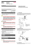
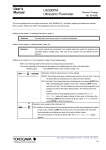
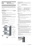
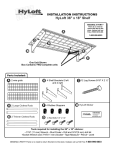
•
User’s
Manual
Model 701962
All-Purpose Instrument Cart
Instrument Size Restrictions
Each shelf can support instruments weighing up to fifty kilograms.
•
Cart Specifications
Item
The Model 701962 All-Purpose Instrument Cart can support large-scale measuring
instruments. Each shelf accepts a maximum load of fifty kilograms, and a drawer is
provided underneath the top shelf for storing measuring instrument parts and accessories.
The cart features a slide-out table that can be used for a keyboard or other items.
Outer (maximum) dimensions
467 mm (W) × 693 mm (D) × 713 mm (H)
Upper/lower shelf dimensions
457 mm (W) × 683 mm (D)
Drawer
610 mm (W) × 380 mm (D)
Slide-out table
380 mm (W) × 440 mm (D)
Casters
100 mm diameter wheels (front casters with stoppers)
Maximum load (per shelf)
50 kg
Cart weight
23.5 kg
• Assembly
1st Edition : April 2004 (YK)
All Rights Reserved, Copyright © 2004, Yokogawa Electric Corporation
Refer to the assembly diagrams when assembling the cart.
IM 701962-01E
1st Edition
1. Assembling the Supports and Lower Shelf
Loosely attach a support to each corner of the lower shelf with a screw.
Safety Precautions
For safe use of this product, please take the following precautions.
•
Keep the Cart Level
As much as possible, use the cart only on horizontal surfaces. When moving a loaded
cart over an inclined or bumpy surface, ensure that the cart does not tip over and that
the instrument does not fall off the cart.
•
Double-Check Safety during Non-Specified Use
Loading an instrument other than the ones recommended onto the cart, or changing the
instrument’s position can alter the balance of the cart. Before use, make sure the cart
does not tip over easily.
•
2. Assembling the Upper Shelf
Place the upper shelf on the open ends of the four supports, then loosely attach the
supports to each corner of the upper shelf with screws.
Ground the Instrument
The cart is not grounded. Ground the instrument loaded on the cart using a 3-wire
power supply cord.
•
Screws
Screws
Do Not Exceed the Maximum Load
Ensure that the weight of the instruments loaded on each shelf does not exceed the
specification.
Outline
Slide-out table
4. Attaching the Casters
Screw the casters into the caster holes located at the four corners of the bottom
shelf. (The two front casters have a stopper).
Drawer
Screw in the
casters
Component Parts
Upper shelf (with drawer and slide-out table)
3. Tightening the Screws
While adjusting any misalignments, tighten all screws securely.
Supports (4)
Casters (2 with stoppers)
Lower shelf
IM 701962-01E