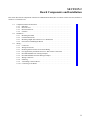
1
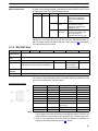
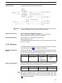
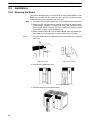
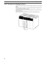
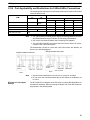
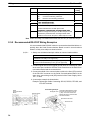
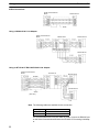
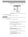
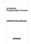
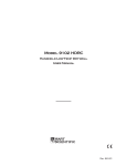
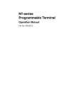
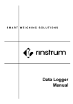
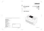
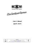
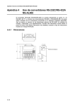
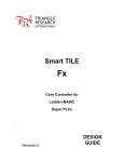
SECTION 2
Board Components and Installation
This section describes the components of the Serial Communications Board, how to connect it in the CPU Unit, and how to
connect it to external devices.
2-1
2-2
2-3
Component Names and Functions . . . . . . . . . . . . . . . . . . . . . . . . . . . . . . . . . . . . . . . . . . . .
2-1-1 Indicators . . . . . . . . . . . . . . . . . . . . . . . . . . . . . . . . . . . . . . . . . . . . . . . . . . . . . . . .
2-1-2 RS-232C Port . . . . . . . . . . . . . . . . . . . . . . . . . . . . . . . . . . . . . . . . . . . . . . . . . . . . .
2-1-3 RS-422A/485 Port . . . . . . . . . . . . . . . . . . . . . . . . . . . . . . . . . . . . . . . . . . . . . . . . .
2-1-4 Switches . . . . . . . . . . . . . . . . . . . . . . . . . . . . . . . . . . . . . . . . . . . . . . . . . . . . . . . . .
Installation . . . . . . . . . . . . . . . . . . . . . . . . . . . . . . . . . . . . . . . . . . . . . . . . . . . . . . . . . . . . . .
2-2-1 Mounting the Board . . . . . . . . . . . . . . . . . . . . . . . . . . . . . . . . . . . . . . . . . . . . . . . .
2-2-2 External Dimensions . . . . . . . . . . . . . . . . . . . . . . . . . . . . . . . . . . . . . . . . . . . . . . .
2-2-3 Mounting Height and Connector Cover Dimensions . . . . . . . . . . . . . . . . . . . . . .
2-2-4 Precautions in Handling the Board . . . . . . . . . . . . . . . . . . . . . . . . . . . . . . . . . . . .
Wiring . . . . . . . . . . . . . . . . . . . . . . . . . . . . . . . . . . . . . . . . . . . . . . . . . . . . . . . . . . . . . . . . . .
2-3-1 Connectors . . . . . . . . . . . . . . . . . . . . . . . . . . . . . . . . . . . . . . . . . . . . . . . . . . . . . . .
2-3-2 Wiring Precautions . . . . . . . . . . . . . . . . . . . . . . . . . . . . . . . . . . . . . . . . . . . . . . . . .
2-3-3 Reducing Electrical Noise for External Wiring . . . . . . . . . . . . . . . . . . . . . . . . . . .
2-3-4 Port Applicability and Restrictions for 2-Wire/4-Wire Connections . . . . . . . . . . .
2-3-5 Recommended RS-232C Wiring Examples . . . . . . . . . . . . . . . . . . . . . . . . . . . . . .
2-3-6 Recommended RS-422A/485 Wiring Examples . . . . . . . . . . . . . . . . . . . . . . . . . .
2-3-7 Wiring Connectors . . . . . . . . . . . . . . . . . . . . . . . . . . . . . . . . . . . . . . . . . . . . . . . . .
2-3-8 Soldering . . . . . . . . . . . . . . . . . . . . . . . . . . . . . . . . . . . . . . . . . . . . . . . . . . . . . . . .
2-3-9 Assembling Connector Hood . . . . . . . . . . . . . . . . . . . . . . . . . . . . . . . . . . . . . . . . .
2-3-10 Connecting to the Board . . . . . . . . . . . . . . . . . . . . . . . . . . . . . . . . . . . . . . . . . . . .
9
Section
Component Names and Functions
2-1
2-1
Component Names and Functions
The components of the Serial Communications Board are described in this section.
Serial Communications Board
(Inner Board slot 1)
Port 1:
RS-232C
Terminating resistance
switch
Applicable Connectors
Socket: XM2SA-0901 (OMRON)
Hood:
XM2SA-0911-E (OMRON)
(Two of each are included with the Board)
2-wire or 4-wire switch
Port 2:
RS-422A/485
2-1-1 Indicators
Board Indicators
There are three LED indicators on the Board, as described below.
RDY: Lit when the Board is operational (green)
RDY
COMM1
COMM2
COMM1: Lit when data is being sent or received on the RS-232C port (Yellow)
COMM2: Lit when data is being sent or received on the RS-442A/485 port (Yellow)
Indicator
RDY
10
Color
Green
COMM1
Yellow
COMM2
Yellow
Status
Meaning
Lit
Operating normally, and protocol macro
preparations have been completed.
Flashing
There is an error in the PC Setup settings for the
Board or in the protocol macros contained in the
Board.
Not lit
Flashing
Not lit
Flashing
Not lit
A hardware error has occurred in the Board.
Port 1 is being used for sending or receiving.
Port 1 is not being used for sending or receiving.
Port 2 is being used for sending or receiving.
Port 2 is not being used for sending or receiving.
Section
Component Names and Functions
CPU Unit Indicators
2-1
A Serial Communications Board is mounted as an Inner Board in the CPU Unit
and thus affects the CPU Unit ERR/ALM indicator.
Indicator
Color
ERR/ALM Red
Status
Meaning
Lit
Fatal error
Flashing
Non-fatal
error
Not lit
Normal
operation
If a fatal error occurs, the CPU
Unit will stop operation in
either RUN or MONITOR
mode.
If a non-fatal error occurs, the
CPU Unit will continue
operation in either RUN or
MONITOR mode.
The CPU Unit is operating
normally. This indicator will
also not be lit when a
watchdog timer error occurs.
If an error in the Inner Board is the cause of the error indicated on the ERR/ALM
indicator, the Inner Board Error Flag (SR 25415) will turn ON and information on
the error will be stored in AR 0400 to AR 0407. Refer to Section 9 Troubleshooting and Maintenance for details.
2-1-2 RS-232C Port
Protocol
Host Link
Communications method
Half-duplex
No-protocol
Protocol macros
1:1 Data Links
Synchronization
Start-stop synchronization (asynchronous)
Baud rate
1,200/2,400/4,800/9,600/ 19,200 bps
19,200 bps
38,400 bps
19,200 bps
Connections
1:1
1:1
1:1
1:1
(1:N possible using Converting Link Adapters)
Transmission
distance
15 m max. (See note)
Interface
Complies with EIA RS-232C
1:N NT Links
1:1 NT Links
(1:N possible using Link Adapters)
Note The maximum cable length for RS-232C is 15 m. The RS-232C standard, however, does not cover baud rates above 19.2 Kbps. Refer to the manual for the
device being connected to confirm support.
Connector Pin Layout
Pin No.
Note
Abbreviation
Signal name
I/O
1 (See note 1)
FG
Shield
---
2
SD
Send data
Output
3
RD
Receive data
Input
4
RTS (RS)
Request to send
Output
5
CTS (CS)
Clear to send
Input
6 (See note 2)
5V
Power supply
---
7
DSR (DR)
Data set ready
Input
8
DTR (ER)
Data terminal ready
(See note 4)
Output
9
SG
Signal ground
---
Shell (See note 1)
FG
Shield
---
1. Pin No. 1 and the shell are connected to the ground terminal (GR) of the
Power Supply Unit inside the Serial Communications Board. Therefore, the
cable shield can be grounded by grounding GR of the Power Supply Unit.
2. Pin 6 (5 V) is required when the NT-AL001-E Link Adapter is connected. For
details on connection methods, refer to 2-3 Wiring.
11
Section
Component Names and Functions
! Caution
2-1
Do not connect the 5-V power supply of pin 6 to any external device other than an
NT-AL001-E Link Adapter. Otherwise, the external device and the Serial Communications Board may be damaged.
The following cables are provided for connection to NT-AL001-E Link Adapters.
We recommend that these cables be used.
NT-AL001-E connecting cables: XW2Z-070T-1 (0.7 m)
XW2Z-200T-1 (2 m)
Applicable Connectors
Socket: XM2A-0901 (OMRON) or equivalent
Hood: XM2S-0911-E (OMRON, conforms to ESD) or equivalent
One Socket and one Hood are provided for each port.
Recommended Cables
UL2464 AWG28 5P IFS-RVV-SB (UL-approved, Fujikura Ltd.)
AWG28 5P IFVV-SB (not UL-approved, Fujikura Ltd.)
UL2464-SB (MA) 5P 28AWG (7/0.127) (UL-approved, Hitachi Cable, Ltd.)
CO-MA-VV-SB 5P 28AWG (7/0.127) (not UL-approved, Hitachi Cable, Ltd.)
Cable length: 15 m max.
2-1-3 RS-422A/485 Port
Protocol
Host Link
No-protocol
Protocol macros
1:1 Data Links
1:N NT Links
1:1 NT Links
Communications method
Half-duplex
4-wire, 1:1
OK
OK
OK
OK
OK
OK
4-wire, 1:N
OK
OK
OK
No
OK
No
2-wire, 1:1
No
No
OK
No
OK
No
2-wire, 1:N
No
No
OK
No
OK
No
Synchronization
Start-stop synchronous (asynchronous)
Baud rate
1,200/2,400/4,800/9,600/ 19,200 bps
19,200 bps
38,400 bps
19,200 bps
Connections
1:N (N: 32 Units max.)
1:1
1:N (N: 8 Units
max.)
1:1
Transmission
distance
500 m max.
(The total combined cable length is 500 m max. T-branch lines must be a maximum of 10 m long.)
Interface
Complies with EIA RS-485
Connector Pin Layout
Pin No.
Note
Abbreviation
Signal name
I/O
1 (See note 1)
SDA
Send data –
Output
2 (See note 1)
SDB
Send data +
Output
3
NC
Not used
---
4
NC
Not used
---
5
NC
Not used
---
6 (See note 1)
RDA
Receive data –
Input
7
NC
Not used
---
8 (See note 1)
RDB
Receive data +
Input
9
NC
Not used
---
Shell (See note 2)
FG
Shield
---
1. When 2-wire connections are used, use pins 1 and 2, or pins 6 and 8.
2. The shell is connected to the ground terminal (GR) of the Power Supply Unit
inside of the Serial Communications Board. Therefore, the cable shield can
be grounded by grounding the GR of the Power Supply Unit.
12
Section
Component Names and Functions
Internal Circuits
2-1
The internal circuits for port 2 are shown below.
Pin 8: RDB (+)
Receiver
Terminating resistance: 200 Ω
Terminating resistance switch
Pin 6: RDA (–)
2-wire/4-wire switch
Pin 2: SDB (+)
Driver
Pin 1: SDA (–)
! Caution
Confirm polarities before connecting RS-422A/485 cables. Some devices require that SDA/B and RDA/B or signal polarities be reversed.
Applicable Connectors
Socket: XM2A-0901 (OMRON) or equivalent
Hood: XM2S-0911-E (OMRON, conforms to ESD) or equivalent
One Socket and one Hood are provided for each port.
Recommended Cables
CO-HC-ESV-3P 7/0.2 (Hirakawa Hewtech Corp.)
Cable length: 500 m max.
(The total combined cable length is 500 m max. T-branch lines must be a maximum of 10 m long.)
2-1-4 Switches
The TERM and WIRE switches are on the front panel of the Serial Communications Board. Refer to page 10 for a diagram of the Board.
Terminating Resistance
Switch
When an RS-422/485 port is used, turn ON the switch if the Serial Communications Board is on the end of the transmission line. Refer to information on specific
serial communications modes for the ON/OFF settings.
Label
TERM
Name
Terminating
resistance switch
Settings
OFF: Terminating
resistance
OFF
Factory setting
OFF: Terminating
resistance
OFF
ON: Terminating
resistance ON
2-Wire or 4-Wire Switch
When an RS-422/485 port is used, set the switch to 2 when 2-wire connections
are used, and set the switch to 4 when 4-wire connections are used.
Label
WIRE
Name
2-wire or 4-wire
switch
Settings
2: 2-wire
Factory setting
2: 2-wire
4: 4-wire
Note Host Link, no-protocol, and 1:1 Data Link modes cannot use 2-wire
RS-422A/485 communications. Always use 4-wire connections when using
RS-422A/485 communications for these serial communications modes. Refer
to 2-3 Wiring for connections.
13
Section
Installation
2-2
2-2
Installation
2-2-1 Mounting the Board
This section describes how to mount a Serial Communications Board in Inner
Board slot 1 of a CPU Unit. Slot 1 is the slot on the left. Only one Serial Communications Board can be installed in each CPU Unit.
Note
1, 2, 3...
1. The Serial Communications Board cannot be mounted in Inner Board slot 2.
2. Always turn OFF the power before installing or removing the Serial Communications Board. Installing or removing the Serial Communications Board
with the power ON can cause the CPU Unit to malfunction, damage internal
components, or cause communications errors.
3. Before handling the Serial Communications Board, touch a grounded metallic object in order to discharge any static build-up from your body.
1. Press the catches at the top and bottom of the Inner Board slot 1 compartment cover.
Press the top catch.
Press the bottom catch.
2. Remove the compartment cover.
Inner Board Connector
3. Insert the Serial Communications Board.
14
Section
Installation
2-2
2-2-2 External Dimensions
Unit: mm
CS1W-SCB41
Mounted in the CPU Unit
110
25
107
2-2-3 Mounting Height and Connector Cover Dimensions
When mounting the Serial Communications Board, make sure to provide space
for the mounting height and connector cover dimensions shown below.
Serial Communication Unit
mounted in the CPU Unit
Connecting Cable connector
123
223
Note The mounting heights shown above are applicable when the attached connectors, connector covers, and recommended cables are used. The mounting
height may differ when other connectors, connector covers, and cables are
used. Determine the mounting height, taking into account the connectors, connector covers, and the minimum bending radius of the cables.
15
Section
Installation
2-2
2-2-4 Precautions in Handling the Board
• Turn OFF the power supply to the CPU Unit before mounting or removing the
Board.
• Turn OFF the power supply to the CPU Unit before before connecting or disconnecting Board connectors or wiring.
• Separate the port connector lines from the high-tension or power lines to reduce external noise.
• Leave the port cover attached when not using a communications port.
Port cover
16
Section
Wiring
2-3
2-3
Wiring
2-3-1 Connectors
Prepare connecting cables for port 1 (RS-232C) and port 2 (RS422A/485) using
the Sockets and Hoods provided with the Board and the recommended cables.
Connection methods vary with the serial communications mode that is being
used. Refer to the following sections for connection examples.
Host Link:
Protocol macros:
No-protocol:
1:1 Data Links:
NT Links:
Section 4 Host Link Communications
Section 5 Protocol Macros
Section 6 Non-protocol Communications
Section 7 Communications for 1:1 Data Links
Section 8 NT Link Communications
Hood
Socket
Standard Connectors
(for Both RS-232C and
RS-422A/485)
Name
Model
Socket
XM2A-0901
Hood
XM2S-0911-E
Socket:
XM2A-0901
Specifications
Used together
(provided with
For 9-pin, metric
Serial
screws, conforms
Communications
to ESD
Board).
9-pin male
Hood:
XM2S-0911-E
Recommended Cables
RS-232C Cables
Model
UL2464 AWG28×5P IFS-RVV-SB (UL-approved)
AWG28×5P IFVV-SB (not UL-approved)
UL2464-SB (MA) 5P×AWG28 (7/0.127) (UL-approved)
CO-MA-VV-SB 5P×AWG28 (7/0.127) (not UL-approved)
Manufacturer
Fujikura Ltd.
Hitachi Cable, Ltd.
17
Section
Wiring
2-3
RS-422A/485 Cable
Model
Manufacturer
CO-HC-ESV-3P×7/0.2
Hirakawa Hewtech Corp.
Refer to pages 11 and 12 for the connector pin layouts. Refer to 2-3-5 Recommended RS-232C Wiring Examples and 2-3-6 Recommended RS-422A/485
Wiring Examples for wiring examples, and to 2-3-7 Wiring Connectors for wiring
methods.
Standard cables are available for connection to personal computers and PTs.
Refer to Section 4 Host Link Communications for personal computer cables and
to your PT user’s manual for PT cables.
2-3-2 Wiring Precautions
• Before connecting or disconnecting the communications cables, always make
sure that the PC is turned OFF.
• Tighten the communications connector screws firmly with your fingers.
• Serial Communications Boards can be connected to various devices. For
compatibility, refer to the operation manuals for the devices to which they are to
be connected.
2-3-3 Reducing Electrical Noise for External Wiring
Observe the following precautions for external wiring.
• When multi-conductor signal cable is being used, avoid using I/O wires and
other control wires in the same cable.
• If wiring racks are running in parallel, allow at least 300 mm between the racks.
Low-current cables
Communications
cables
Control cables
PC power supply
and general control
circuit wiring
Power cables
300 mm min.
300 mm min.
Power lines
Ground to 100 Ω or less.
• If the I/O wiring and power cables must be placed in the same duct, they must
be shielded from each other using grounded steel sheet metal.
Communications
cables
PC power supply
and general control
circuit wiring
Power lines Steel sheet metal
200 mm min.
Ground to 100 Ω or less.
18
Section
Wiring
2-3
2-3-4 Port Applicability and Restrictions for 2-Wire/4-Wire Connections
The following table shows the port connections that can be used for each serial
communications mode.
RS-232C port
Serial communications
mode
d
1:1
RS-422A/485 port
1:N
4-wire
1:1
Host Link
OK
Protocol macros
No-protocol
1:1 Data Links
OK
1:N-mode NT Links
OK
1:1-mode NT Links
OK
1:N
OK
No
No
OK
OK
OK
OK
OK
OK
OK
OK
No
No
OK
No
No
No
OK
OK
OK
OK
OK
No
No
No
No
No
1. The 1:N connection method can be used by converting between RS-232C
and RS-422A/485 through NT-AL001-E Converting Link Adapters.
2. Use 4-wire connections between the Converting Link Adapters.
3. The 2-wire RS-422A/485 connections cannot be used for Host Link communications. Use 4-wire connections.
The transmission circuits for 2-wire and 4-wire connections are different, as
shown in the following diagram.
Example of 2-Wire Connections
Example of 4-Wire Connections
2/4-wire switch
(DPDT)
2/4-wire switch
(DPDT)
Other Unit
Other Unit
Board
Board
Note
NT-AL001-E Link Adapter
Settings
1:1
OK
Note
OK (See
note 2)
2-wire
1:N
Other Unit
Not connected
Other Unit
1. Use the same transmission circuit (2-wire or 4-wire) for all nodes.
2. Do not use 4-wire connections when the 2/4-wire switch on the Board is set
to 2-wire.
The NT-AL001-E Link Adapter has a DIP switch for setting RS-422A/485 communications conditions. When connecting the Board, refer to the DIP switch settings shown in the following table.
19
Section
Wiring
Pin
Function
2-3
Factory
setting
1
Not used. Always set this pin to ON.
ON
2
Built-in terminating resistance setting
ON
3
ON:
Connects terminating resistance.
OFF:
Disconnects terminating resistance.
2/4-wire setting
OFF
4
2 wire Set both pins to ON.
ON
2-wire:
4-wire: Set both pins to OFF.
OFF
5
Transmission mode (See note)
ON
Constant transmission: Set both pins to OFF.
Transmission performed
erformed when CTS signal in RS-232C
interface is at high level: Set pin 5 to OFF and pin 6 to ON.
6
OFF
Transmission performed when CTS signal in RS-232C
interface is at low level: Set pin 5 to ON and pin 6 to OFF.
Note When connecting to a CQM1H-series CPU Unit, turn OFF pin 5 and turn ON pin 6.
2-3-5 Recommended RS-232C Wiring Examples
It is recommended that RS-232C cables be connected as described below, especially when the Serial Communications Board is used in an environment
where it is likely to be subject to electrical noise.
1, 2, 3...
1. Always use shielded twisted-pair cables as communications cables.
Model
Manufacturer
UL2464 AWG28x5P IFS-RVV-SB (UL-approved)
AWG28x5P IFVV-SB (not UL-approved)
UL2464-SB (MA) 5Px28AWG (7/0.127) (UL-approved)
CO-MA-VV-SB 5Px28AWG (7/0.127) (not UL-approved)
Fujikura Ltd.
Hitachi Cable,
Ltd.
2. Combine signal wires and SG (signal ground) wires in a twisted-pair cable.
At the same time, bundle the SG wires to the connectors on the Serial Communications Board and the remote device.
3. Connect the shield of the communications cable to the Hood (FG) terminal
of the RS-232C connector on the Serial Communications Board. At the
same time, ground the ground (GR) terminal of the Power Supply Unit to
100 Ω or less.
4. A connection example is shown below.
Example: Twisted-pair Cable Connecting SD-SG, RD-SG, RTS-SG, and
CTS-SG Terminals
Actual Wiring Example
Serial
Communications
Board
Pin
Twist the braided shield to make
SG signal wires it thinner and connect to Pin No.
1 (FG). Cover this section with
heat-shrink tube to avoid contact
with other sections.
Remote device
Signal
Signal
SD
RD
RTS
CTS
SG
Hood FG
FG
RD
SD
CTS
RTS
SG
FG
Bundle the SG wires.
Aluminum foil
Shield
XM2S-0911-E
20
Section
Wiring
2-3
Note The Hood (FG) is internally connected to the ground terminal (GR) on the Power
Supply Unit. Therefore, FG is grounded by grounding the ground terminal (GR)
on the Power Supply Unit. Although there is conductivity between the Hood (FG)
and pin 1 (FG), connect the Hood (FG) to the shield because the Hood (FG) has
smaller contact resistance with the shield than pin 1 (FG), and thus provides better noise resistance.
Serial Communications Board
Power Supply Unit
Ground to 100 Ω or less
Hood and GR are
internally connected.
Grounding the GR terminal
grounds the Hood (FG).
2-3-6 Recommended RS-422A/485 Wiring Examples
Recommended RS-422A/485 Cable
We recommend the following wiring methods to ensure quality transmissions for
RS-422A/485 communications.
1, 2, 3...
1. Always use shielded twisted-pair cables for the communications cables.
Model
CO-HC-ESV-3Px7/0.2
Manufacturer
Hirakawa Hewtech Corp.
2. Connect the shield of the communications cable to the Hood (FG) of the
RS-422A/485 connector on the Serial Communications Board. At the same
time, ground the ground (GR) terminal of the Power Supply Unit to 100 Ω or
less.
Note Always ground the shield only at the Board end. Grounding both ends of the
shield may damage the device due to the potential difference between the
ground terminals.
Connection examples are shown below.
2-Wire Connections
Serial Communications
Board
Remote device
Pin Signal
Hood
Signal
Shield
21
Section
Wiring
2-3
4-Wire Connections
Serial Communications
Board
Remote device
Signal
Signal
Pin
Hood
Shield
Using a 3G2A9-AL001 Link Adapter
Serial Communications
Board
Pin Signal
3G2A9-AL001
Pin Signal
Remote device
Signal
Signal Pin
RS-422
interface
Hood
Signal
Pin
Remote device
Signal
Using an NT-AL001-E RS-232C/RS-422 Link Adapter
Serial Communications
Board
NT-AL001-E
Pin
Pin Signal
Signal
Signal Pin
RD
SD
CTS
RTS
5V
DSR
DTR
SG
SD
RD
RTS
CTS
5V
DSR
DTR
SG
Hood FG
Remote device
Signal
Remote device
Shield
(See note.)
Signal
Note The following cables are available for this connection.
Length
Model
70 cm
XW2Z-070T-1
2m
XW2Z-200T-1
It is recommended that one of these cables be used to connect the RS-232C port
on the Serial Communications Board to the NT-AL001-E Converting Link Adapter.
22
Section
Wiring
2-3
Note The Hood (FG) is internally connected to the ground terminal (GR) on the Power
Supply Unit. Therefore, FG is grounded by grounding the ground terminal (GR)
on the Power Supply Unit.
Serial Communications Board
Power Supply Unit
Ground to 100 Ω or less
Hood and GR are
internally connected.
Grounding the GR terminal
grounds the Hood (FG).
3. Be sure to turn ON the terminating resistance at the last Unit at the end of the
RS-422A/485 cable.
2-3-7 Wiring Connectors
Use the following steps to wire connectors.
Cable Preparation
See the following diagrams for the length of the cable portion to be cut in each
step.
Shield Connected to Hood (FG)
1, 2, 3...
1. Cut the cable to the required length.
2. Remove the specified length of the sheath from the cable using a knife. Be
careful not to scratch the braided shield.
25 mm (RS-422A)
40 mm (RS-232C)
3. Trim off the braided shield using scissors so that the remaining shield length
is 10 mm.
10 mm
4. Remove the insulation from each conductor using a stripper so that the exposed conductor length is 5 mm.
5 mm
23
Section
Wiring
2-3
5. Fold back the braided shield.
6. Wrap aluminum foil tape around the folded shield.
Aluminum foil tape
Shield Not Connected to Hood (FG)
1, 2, 3...
1. Cut the cable to the required length.
2. Remove the specified length of the sheath from the cable using a knife. Be
careful not to scratch the braided shield.
25 mm (RS-422A)
40 mm (RS-232C)
3. Trim off all the braided shield using scissors.
4. Remove the insulation from each conductor using a stripper so that the exposed conductor length is 5 mm.
5 mm
5. Wrap adhesive tape around the conductor from which the braided shield
was removed.
Adhesive tape
24
Section
Wiring
2-3
2-3-8 Soldering
1, 2, 3...
1. Thread a heat-shrinking tube through each conductor.
2. Temporarily solder each conductor to the corresponding connector terminals.
3. Completely solder each conductor.
Soldering iron
Heat-shrinking tube
Inside diameter:
1.5 mm, l = 10
4. Return the heat-shrinking tube to the soldered portion, then heat the tube to
shrink it in place.
Heat-shrinking tube
2-3-9 Assembling Connector Hood
Assemble the connector Hood as shown below.
End connected to FG
Adhesive tape
End not connected to FG
Aluminum foil tape
Grounding plate
25
Section
Wiring
2-3-10 Connecting to the Board
Tighten the screws firmly
with your fingers.
26
2-3