Download proces-rm006 - Literature Library
Transcript
Reference Manual Rockwell Automation Sequencer Object Version 3.1 Important User Information Read this document and the documents listed in the additional resources section about installation, configuration, and operation of this equipment before you install, configure, operate, or maintain this product. Users are required to familiarize themselves with installation and wiring instructions in addition to requirements of all applicable codes, laws, and standards. Activities including installation, adjustments, putting into service, use, assembly, disassembly, and maintenance are required to be carried out by suitably trained personnel in accordance with applicable code of practice. If this equipment is used in a manner not specified by the manufacturer, the protection provided by the equipment may be impaired. In no event will Rockwell Automation, Inc. be responsible or liable for indirect or consequential damages resulting from the use or application of this equipment. The examples and diagrams in this manual are included solely for illustrative purposes. Because of the many variables and requirements associated with any particular installation, Rockwell Automation, Inc. cannot assume responsibility or liability for actual use based on the examples and diagrams. No patent liability is assumed by Rockwell Automation, Inc. with respect to use of information, circuits, equipment, or software described in this manual. Reproduction of the contents of this manual, in whole or in part, without written permission of Rockwell Automation, Inc., is prohibited. Throughout this manual, when necessary, we use notes to make you aware of safety considerations. WARNING: Identifies information about practices or circumstances that can cause an explosion in a hazardous environment, which may lead to personal injury or death, property damage, or economic loss. ATTENTION: Identifies information about practices or circumstances that can lead to personal injury or death, property damage, or economic loss. Attentions help you identify a hazard, avoid a hazard, and recognize the consequence. IMPORTANT Identifies information that is critical for successful application and understanding of the product. Labels may also be on or inside the equipment to provide specific precautions. SHOCK HAZARD: Labels may be on or inside the equipment, for example, a drive or motor, to alert people that dangerous voltage may be present. BURN HAZARD: Labels may be on or inside the equipment, for example, a drive or motor, to alert people that surfaces may reach dangerous temperatures. ARC FLASH HAZARD: Labels may be on or inside the equipment, for example, a motor control center, to alert people to potential Arc Flash. Arc Flash will cause severe injury or death. Wear proper Personal Protective Equipment (PPE). Follow ALL Regulatory requirements for safe work practices and for Personal Protective Equipment (PPE). Allen-Bradley, Rockwell Software, Rockwell Automation, RSLogix, Logix5000, FactoryTalk, PlantPAx, and ControlLogix are trademarks of Rockwell Automation, Inc. Trademarks not belonging to Rockwell Automation are property of their respective companies. Table of Contents Preface Software Compatibility and Content Revision. . . . . . . . . . . . . . . . . . . . . . . . 5 Additional Resources . . . . . . . . . . . . . . . . . . . . . . . . . . . . . . . . . . . . . . . . . . . . . . . 6 Rockwell Automation Sequencer Object (P_Seq) Guidelines . . . . . . . . . . . . . . . . . . . . . . . . . . . . . . . . . . . . . . . . . . . . . . . . . . . . . . . . . 7 Functional Description . . . . . . . . . . . . . . . . . . . . . . . . . . . . . . . . . . . . . . . . . . . . . 8 Step User-defined Type . . . . . . . . . . . . . . . . . . . . . . . . . . . . . . . . . . . . . . . . . 8 Operator Prompt. . . . . . . . . . . . . . . . . . . . . . . . . . . . . . . . . . . . . . . . . . . . . . . 9 State Machine. . . . . . . . . . . . . . . . . . . . . . . . . . . . . . . . . . . . . . . . . . . . . . . . . . 9 Step Timer. . . . . . . . . . . . . . . . . . . . . . . . . . . . . . . . . . . . . . . . . . . . . . . . . . . . . 9 Branching and Looping . . . . . . . . . . . . . . . . . . . . . . . . . . . . . . . . . . . . . . . . . 9 Alarm Options . . . . . . . . . . . . . . . . . . . . . . . . . . . . . . . . . . . . . . . . . . . . . . . 10 Sequencer Demonstration. . . . . . . . . . . . . . . . . . . . . . . . . . . . . . . . . . . . . 11 Programming Example . . . . . . . . . . . . . . . . . . . . . . . . . . . . . . . . . . . . . . . . . . . 18 Configuring the Sequencer . . . . . . . . . . . . . . . . . . . . . . . . . . . . . . . . . . . . 20 Configuring the Sequence Steps . . . . . . . . . . . . . . . . . . . . . . . . . . . . . . . 25 Branch on Input. . . . . . . . . . . . . . . . . . . . . . . . . . . . . . . . . . . . . . . . . . . . . . 31 Multi-Step Configuration Dialog Box . . . . . . . . . . . . . . . . . . . . . . . . . 32 Required Files . . . . . . . . . . . . . . . . . . . . . . . . . . . . . . . . . . . . . . . . . . . . . . . . . . . 34 Controller File . . . . . . . . . . . . . . . . . . . . . . . . . . . . . . . . . . . . . . . . . . . . . . . 34 Visualization Files . . . . . . . . . . . . . . . . . . . . . . . . . . . . . . . . . . . . . . . . . . . . 34 Controller Code . . . . . . . . . . . . . . . . . . . . . . . . . . . . . . . . . . . . . . . . . . . . . . . . . 36 Sequencer Object InOut Structure. . . . . . . . . . . . . . . . . . . . . . . . . . . . . 36 Sequencer Object Input Structure . . . . . . . . . . . . . . . . . . . . . . . . . . . . . 36 Sequencer Object Output Structure. . . . . . . . . . . . . . . . . . . . . . . . . . . . 40 Sequencer Object Local Configuration Tags . . . . . . . . . . . . . . . . . . . . 44 Operations . . . . . . . . . . . . . . . . . . . . . . . . . . . . . . . . . . . . . . . . . . . . . . . . . . . . . . 45 Modes . . . . . . . . . . . . . . . . . . . . . . . . . . . . . . . . . . . . . . . . . . . . . . . . . . . . . . . 45 Alarms . . . . . . . . . . . . . . . . . . . . . . . . . . . . . . . . . . . . . . . . . . . . . . . . . . . . . . 45 Simulation . . . . . . . . . . . . . . . . . . . . . . . . . . . . . . . . . . . . . . . . . . . . . . . . . . . 46 Execution. . . . . . . . . . . . . . . . . . . . . . . . . . . . . . . . . . . . . . . . . . . . . . . . . . . . 46 Display Element . . . . . . . . . . . . . . . . . . . . . . . . . . . . . . . . . . . . . . . . . . . . . . . . . 46 Status/Quality Indicators . . . . . . . . . . . . . . . . . . . . . . . . . . . . . . . . . . . . . 47 Maintenance Bypass Indicator . . . . . . . . . . . . . . . . . . . . . . . . . . . . . . . . . 48 Mode Indicators. . . . . . . . . . . . . . . . . . . . . . . . . . . . . . . . . . . . . . . . . . . . . . 48 Alarm Indicators . . . . . . . . . . . . . . . . . . . . . . . . . . . . . . . . . . . . . . . . . . . . . 49 Using Display Elements . . . . . . . . . . . . . . . . . . . . . . . . . . . . . . . . . . . . . . . 50 Quick Display . . . . . . . . . . . . . . . . . . . . . . . . . . . . . . . . . . . . . . . . . . . . . . . . . . . 52 Faceplate . . . . . . . . . . . . . . . . . . . . . . . . . . . . . . . . . . . . . . . . . . . . . . . . . . . . . . . . 52 Operator Tab . . . . . . . . . . . . . . . . . . . . . . . . . . . . . . . . . . . . . . . . . . . . . . . . 53 Maintenance Tab. . . . . . . . . . . . . . . . . . . . . . . . . . . . . . . . . . . . . . . . . . . . . 57 Engineering Tab. . . . . . . . . . . . . . . . . . . . . . . . . . . . . . . . . . . . . . . . . . . . . . 62 Configuring a Range for Scaling Parameters . . . . . . . . . . . . . . . . . . . . 64 Diagnostics Tab . . . . . . . . . . . . . . . . . . . . . . . . . . . . . . . . . . . . . . . . . . . . . . 65 Alarms Tab . . . . . . . . . . . . . . . . . . . . . . . . . . . . . . . . . . . . . . . . . . . . . . . . . . 66 Sequencer Faceplate Help . . . . . . . . . . . . . . . . . . . . . . . . . . . . . . . . . . . . . 68 Rockwell Automation Publication PROCES-RM006B-EN-P - August 2014 3 Table of Contents Notes: 4 Rockwell Automation Publication PROCES-RM006B-EN-P - August 2014 Preface This document is updated throughout for version 3.1 of the Rockwell Automation Sequencer Object. Changes for this revision are marked by change bars shown in the right margin. Software Compatibility and Content Revision Table 1 - Summary of Changes Topic Page Changed title from 'PlantPAx® Library of Process Objects' to 'Rockwell Automation Sequencer Object' Front Cover Changed version of Rockwell Automation Sequencer Object from 3.0 to 3.1 5, 34, 35 Changed references to Knowledgebase Answer ID 62682 to Product Compatibility and Download Center 5, 34 Added Important notes: display availability in FactoryTalk® Machine Edition (ME) software Run Time Detail faceplate is not available in FactoryTalk View ME software Multiple Step Sequence Configuration button is not available for FactoryTalk View ME software configuration display has minor differences for FactoryTalk View ME software Multi-Step Configuration Dialog Box is available only in FactoryTalk View SE software Visualization File Types table: added Important note concerning the order files are to be imported added Optional Graphic Displays section updated FactoryTalk View (ME) entries 7 12 20 28 32 34 35 Input Parameters table: added 'PSet_, OSet_, MSet_' parameter description to bullet list added 'Alias For' column and aliases added 'MCmd_Acq', 'MCmd_Rel', 'Cfg_ProgDefault', and 'OCmd_StdQtyReset' parameters 'Cfg_IOFaultSeverity' - changed level 4 alarm severity from 'Highest' to 'Urgent' 36 Output Parameters table: added 'Nrdy_', 'Err_', Ack_', 'and Alm_', parameter descriptions to bullet list added 'Alias For' column and aliases added 'Nrdy_CfgError', 'Nrdy_Intlk', 'Nrdy_Perm', 'Nrdy_NoMode', 'Sts_MAcqRcvd', and 'Rdy_StdQtyReset' parameters 'Val_Notify' - changed level 4 alarm severity from 'Highest' to 'Urgent' 40 Operations - added Simulation section 46 Status/Quality Indicators table: added symbol and description for 'Device disabled' added list of conditions under which Device Not Ready indicator appears changed level 4 alarm severity from 'Highest' to 'Urgent' 47 Operator tab: added Interlock and Permissive descriptive paragraph and links to documents added alarm location image 55 Maintenance tab - added Force Timer section 58 Diagnostics tab - added section 65 For the latest compatible software information and to download the Rockwell Automation Library, see the Product Compatibility and Download Center at http://www.rockwellautomation.com/rockwellautomation/support/ downloads.page?. Rockwell Automation Publication PROCES-RM006B-EN-P - August 2014 5 Preface Additional Resources These documents contain additional information concerning related products from Rockwell Automation. Resource Description PlantPAx Process Automation System Selection Guide, publication PROCES-SG001 Provides information to assist with equipment procurement for your PlantPAx system. PlantPAx Process Automation System Reference Manual, publication PROCES-RM001 Provides characterized recommendations for implementing your PlantPAx system. Rockwell Automation Library of Process Objects, publication PROCES-RM002 Provides general considerations for the Rockwell Automation system library of process objects. FactoryTalk® View Machine Edition User Manual, publication VIEWME-UM004 Provides details on how to use this software package for creating an automation application. FactoryTalk View Site Edition User Manual, publication VIEWSE-UM006 Provides details on how to use this software package for developing and running human-machine interface (HMI) applications that can involve multiple users and servers, distributed over a network. Logix5000™ Controllers Add-On Instructions Programming Manual, publication 1756-PM010 Provides information for designing, configuring, and programming Add-On Instructions. Rockwell Automation Library of Process Objects: Common Alarm Block (P_Alarm) Reference Manual, publication SYSLIB-RM002 Details how to monitor an input condition to raise an alarm. Information includes acknowledging, resetting, inhibiting, and disabling an alarm. Generally the P_Alarm faceplate is accessible from the Alarms tab. Rockwell Automation Library of Process Objects: Interlocks with First Out and Bypass (P_Intlk) Reference Manual, publication SYSLIB-RM004 Explains how to collect (sum up) the interlock conditions that stop or de-energize a running or energized piece of equipment or prevent it from starting or being energized. Rockwell Automation Library of Process Objects: Common Mode Block (P_Mode) Reference Manual, publication SYSLIB-RM005 Explains how to choose the Mode (owner) of an instruction or control strategy. The Mode instruction is usually embedded within other instructions to extend their functionality. It is possible to use a standalone Mode instruction to enhance a program where modes are wanted. Rockwell Automation Library of Process Objects: Permissives with Bypass (P_Perm) Reference Manual, publication SYSLIB-RM007 Details how to collect permissive conditions to start a piece of equipment. Rockwell Automation Library of Process Objects: Operator Prompt Reference Manual, publication SYSLIB-RM046 Explains how to set up and use the Operator Prompt. The instruction can prompts an operator with various types of information (message or data) and accepts operator-input data and confirmation. You can view or download publications at http:/www.rockwellautomation.com/literature/. To order paper copies of technical documentation, contact your local Allen-Bradley distributor or Rockwell Automation sales representative. 6 Rockwell Automation Publication PROCES-RM006B-EN-P - August 2014 Rockwell Automation Sequencer Object (P_Seq) The Rockwell Automation Sequencer Object (P_Seq) provides a flexible controller-based step sequencing solution that reduces engineering time by automating common operator procedures. The step-by-step configuration makes it easy to adjust procedures directly from the HMI displays without having to create or modify custom code in the controller. The Sequencer can be employed in simple and complex sequences without costly re-engineering and testing. You add, delete, or modify steps needed to accomplish your sequence’s objective. The global object and faceplate shown below are examples of the graphical interface tools for this Add-On Instruction. Add-On Instruction Faceplate Global Object Guidelines The P_Seq Add-On Instruction and graphics provide bit-based sequencing with the following features: • Up to 32 discrete (BOOL) outputs for controlling or commanding devices • Up to 32 discrete (BOOL) inputs for monitoring device feedback • Up to 32 floating-point number (REAL) outputs for setpoints or parameter values • A maximum of 500 steps • Rich and intuitive human-machine interface (HMI) screens for operation, monitoring, and configuration IMPORTANT Not all displays are available for FactoryTalk View Machine Edition (ME) software. • Short Add-On Instruction scan time for use in fast-scan control strategies Rockwell Automation Publication PROCES-RM006B-EN-P - August 2014 7 Rockwell Automation Sequencer Object (P_Seq) • State model consistent with higher-level procedural control, with states for Idle, Running, Complete, Held, Paused, and Stopped Use this instruction in these situations: • You need to implement a procedure to operate equipment in a prescribed order (open valve, start pump, and so forth). A procedure is described in the International Society of Automation Technical Report ISA-TR106.00.01-2013 as the following: ‘A specification of a sequence of actions or activities with a defined beginning and end that is intended to accomplish a specific objective’. Although the Sequencer is intended for basic sequencing that is typical of control and equipment implementation modules (as defined in TRI06.00.01), the P_Seq instruction can be used at any level and in any application where its functionality is appropriate. Do not use this instruction in these situations: • The implementation of a batch phase, such as material addition, agitation, transfer, and so forth, where holding, restarting, or resetting logic is required. Use the Phase Manager cpability of Logix Controller insteqad. • If you need sophisticated Sequential Function Chart (SFC) procedures, such as simultaneous threads and multi-selection branches. Functional Description The 32 Boolean outputs are used to assert commands to devices. The 32 Real outputs are used to set setpoints or references. Each output (Boolean or Real) can be used optionally in each step, and each output is explicitly defined even if it’s not used in a step. The 32 inputs are used to monitor Boolean signals from devices or logic to determine when a desired state or combination of states, have been achieved, signaling the end of the step. In operation, when a step is executed, the output values are presented at the Sequencer instruction outputs before the first check of the input conditions. In this way the output values for each step are present for at least one scan of the Sequencer. Step User-defined Type To achieve the greatest flexibility with regard to step information storage and number of steps in a sequence, a separate user-defined type (UDT) is supplied to store the step information (P_SeqStep). You create an array of these UDT members to hold the step configurations of the sequence. Array length is from 2…500 steps. The first step of the array is not available because it’s used by the Sequencer instruction for other features and bookkeeping. 8 Rockwell Automation Publication PROCES-RM006B-EN-P - August 2014 Rockwell Automation Sequencer Object (P_Seq) Operator Prompt The P_Prompt instruction can be used with the Sequencer to perform manual prompt operations, such as operator messaging, entering values, or decisionmaking in the flow of steps. See Rockwell Automation Library of Process Objects: Operator Prompt Reference Manual, publication SYSLIB-RM046 for more information on the Operator Prompt. State Machine The P_Seq instruction executes the following state machine. IMPORTANT No procedural steps are executed in the Idle, Starting, Held, Complete, or Stopped states. The only action is outputs are commanded to their configured positions. Step Timer Each step has an optional timer which, when configured, is included in the qualification conditions of the step, along with the Boolean inputs configured. The timer configuration options provide the flexibility for the following type of scenarios: • Timing when entering a step • Timing after inputs are qualified Branching and Looping The Sequencer normally proceeds from one step to the next through the array of steps. The Sequencer can be configured for four different types of branching to accommodate looping and decisions. Branching lets the Sequencer ‘jump’ to another step, and not necessarily run steps in sequential order. Rockwell Automation Publication PROCES-RM006B-EN-P - August 2014 9 
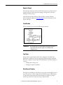
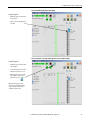
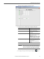
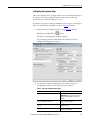
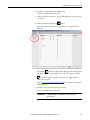
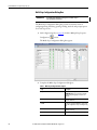
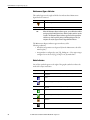
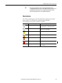
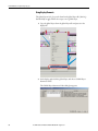
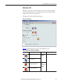
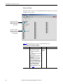
Rockwell Automation Sequencer Object (P_Seq) If branching is configured for a step there are four options: • Continuous - Always take a branch • Loop count - Take a branch until the step has been executed a given number of times • Input pattern - Take a branch if a specific input pattern exists within the Boolean inputs • Manual prompt - Configure the manual prompt to prompt you for a branching decision See page 31 for more information. Alarm Options There are three optional alarms that can be configured to instruct the Sequencer to take a particular action if an alarm occurs. The Alarm Summary tab shows one of these records. • Interlock Trip - Alerts you that an interlock condition has been triggered. • Sequence Timeout - Alerts you that a sequence has run longer than expected. • Step Timeout - Alerts you that a step has run longer than expected. Engineering configuration options let you determine what action the Sequencer is to take if an interlock trips, if the Step Fault Timer expires, or the Sequencer Fault Timer expires. 10 Rockwell Automation Publication PROCES-RM006B-EN-P - August 2014 Rockwell Automation Sequencer Object (P_Seq) Sequencer Demonstration This section illustrates basic Sequencer functionality. Figures show the faceplates for each step in our example sequence. The Sequencer is the engine doing the work and the sequence is the order of actions to complete a procedure. There are a multitude of lists of procedures that you can use with the Sequencer. This example uses an ordinary list to automate how to ignite a water heater. 1. Click the display element for the sequence. Our example is Heater Ignition. The Operator tab appears with buttons to operate the Sequencer. Rockwell Automation Publication PROCES-RM006B-EN-P - August 2014 11 Rockwell Automation Sequencer Object (P_Seq) The Sequencer operator buttons from left to right: • Start command • Stop command • Reset command Access to Detail Faceplate Current Step and Sequence Timers Sequence Control and Pause Management Buttons These same buttons also are available on the Run Time Detail faceplate that visually arranges the progress of the sequential steps. 2. Click the magnifying glass IMPORTANT to access the Run Time Detail faceplate. The Run Time Detail faceplate is different for FactoryTalk View SE software and FactoryTalk View ME software. (See FactoryTalk View ME on page 14.) Sequencer Operator Buttons Steps of Sequence Inputs Icons toggle between the digital and analog outputs Outputs 12 Rockwell Automation Publication PROCES-RM006B-EN-P - August 2014 Rockwell Automation Sequencer Object (P_Seq) IMPORTANT The figures in the following procedure are for FactoryTalk View SE software except as noted. FactoryTalk View ME software shows only the inputs for the active step and does not show input requirements for inactive steps. 3. On the FactoryTalk View SE or ME Operator Detail faceplate, click the Start command button. Step 1: Purge (Verify pilot and main off for 1 minute) FactoryTalk View SE Step Progress • Column turns green to show the current step is in progress. Column turns yellow if a running sequence is held. • For this step configuration, outputs are set to zero (0) for Off. • Button turns blue to indicate On (1 for true) when the Sequencer verifies the pilot valve and main valve are closed. • When the tip of the symbol points up the input must be On to qualify; when the tip is down the input must be Off to qualify. When the input condition is qualified, a black dot appears in the middle of the icon. • The step wait timer starts after all the input conditions have been qualified. The shaded areas on the icon signify if the timer starts after the qualification of the step (shading on the right side) or at the beginning of the step (shading on the left side) per user configuration. Rockwell Automation Publication PROCES-RM006B-EN-P - August 2014 13 Rockwell Automation Sequencer Object (P_Seq) FactoryTalk View ME Step Progress • Column turns green to show the current step is in progress. Column turns yellow if a running sequence is held. • For this step configuration, outputs are set to zero (0) for Off. • Button turns blue to indicate On (1 for true) when the Sequencer verifies the pilot valve and main valve are closed. • When the tip of the symbol points up the input must be On to qualify; when the tip is down the input must be Off to qualify. When the input condition is qualified, a black dot appears in the middle of the icon. • The step wait timer starts after all the input conditions have been qualified. • When the arrow is clicked, the second set of 16 inputs and outputs are displayed. An arrow appears near the top of the page that toggles back to the first set of inputs and Outputs. This action is the same for FactoryTalk SE and ME software. IMPORTANT Step 2: Open Pilot The rest of the faceplates in this example are for FactoryView SE software. (Set pilot on) Step Progress • Column turns green to show the current step is in progress. • The Pilot output (far right column) displays a ‘1’ for true; this is a request for the pilot valve to be open. • Pilot valve is opened (shown by a blue circle). • Black dot in the icon signifies this condition is qualified. 14 Rockwell Automation Publication PROCES-RM006B-EN-P - August 2014 Rockwell Automation Sequencer Object (P_Seq) Step 3: Ignite (Trigger ignitor) Step Progress • Column turns green to show the current step is in progress. • Sequencer ignites the pilot and the step wait timer starts. • The Ignition output displays a ‘1’ for true; requesting ignitor on. Step 4: Check if Lit (Verify Lit a. If lit, proceed to step 7 b. If not lit, after 3 retries close valves) Step Progress • Column turns green to show the current step is in progress. • Sequencer checks if the pilot is lit. • If lit, the ignitor turns off (‘0’ in output). The sequence branches to step 7. • If not lit, ignitor turns off and the sequence branches back to step 3 to re-ignite the pilot. If the loop count reaches the maximum number of attempts, a fault condition can be set. Rockwell Automation Publication PROCES-RM006B-EN-P - August 2014 15 Rockwell Automation Sequencer Object (P_Seq) Step 5: Repeat 3x (If lit, proceed to step 7) Step Progress • Column turns green to show the current step is in progress based on input conditions. • If pilot is lit, branch to step 7. • If pilot is unlit, branch to step 3 to retry igniting the pilot. • After a third unsuccessful attempt to ignite the pilot, proceed to step 6. Step 6: Ignition Failure (Set pilot off, set main fuel off; fault notify) Step Progress • Column turns green to show the current step is in progress. • Sequencer enables output to prompt a fault if pilot not lit after three tries. An operator can interact with discrete inputs/outputs or a HMI-based prompt. • Sequencer waits per timer setting for fault to be acknowledged. • After a fault is acknowledged, the sequence branches to the end. 16 Rockwell Automation Publication PROCES-RM006B-EN-P - August 2014 Rockwell Automation Sequencer Object (P_Seq) Step 7: Open Main Supply (Open main supply) Step Progress • Column turns green to show the current step is in progress. • Sequencer opens the main supply valve, ‘1’ in output. Step 8: Set Temp SP (Set temperature setpoint to 120 °F and shut off pilot) Step Progress • Column turns green to show the current step is in progress. • Once the heater is lit, pilot is closed, the temperature setpoint is set to 120 °F. • When the Sequence is done, the status reads ‘Complete’ and the reset icon appears active (in color). Tip: At the end of the sequence, the Sequencer steps through the remaining steps. Set a branch to the last step to complete the sequence faster. Rockwell Automation Publication PROCES-RM006B-EN-P - August 2014 17 Rockwell Automation Sequencer Object (P_Seq) Programming Example This section describes how to program the individual steps of the sequence shown in the Sequencer demonstration, starting on page 11. 1. Create the P_Seq instruction in your program and give the instruction a name. TIP The screen examples show portions of the ladder logic diagram. You also can use the P_Seq instruction in function block diagrams and structured text language. 2. Crate the new tags, one for the P_Seq instruction, and one for the step array. The name of the Ref_Steps tag must equal the tag name of the Sequencer plus ‘_Steps’. Our example is ‘Heater_Steps’. The faceplate looks for this tag name for step configuration details. When you create the step array tag, type a number into the bracket of the array tag (P_SeqStep) to configure the number of steps to be included in the sequence. The actual number of usable steps in a sequence is the array length minus one. For example, if you type ‘12’, you have 11 usable steps. 18 Rockwell Automation Publication PROCES-RM006B-EN-P - August 2014 Rockwell Automation Sequencer Object (P_Seq) 3. Attach the devices associated with the sequence. This example shows a few of the rungs linking the Sequencer to two P_ValveSO objects for the pilot and main gas valves, a P_DIn object for the flame sensor, a P_DOut object for the ignitor, and a temperature setpoint. 4. Save the file and download. 5. If you make modifications from the HMI, save the .acd file again. Rockwell Automation Publication PROCES-RM006B-EN-P - August 2014 19 Rockwell Automation Sequencer Object (P_Seq) There are buttons (circled) at the top and bottom of the Engineering tab of the P_Seq instruction to access additional dialog boxes to configure the Sequencer and the sequence, respectively. For descriptions of the entry boxes, see page 62. Overall Sequence and Sequencer Input and Output Configuration Step-by-step Sequence Configuration IMPORTANT Multiple Step Sequence Configuration The Multiple Step Sequence Configuration button in the above figure is not available for FactoryTalk View ME software. Configuring the Sequencer You must define what the Sequencer is capable of controlling and monitoring by specifying the attributes of the inputs and outputs. 1. To configure how many inputs are being used by the Sequencer, click the Display Sequence Config Window 20 Rockwell Automation Publication PROCES-RM006B-EN-P - August 2014 button. Rockwell Automation Sequencer Object (P_Seq) The Discrete Input Configuration dialog box appears. 2. Complete the Discrete (BOOL) Input Configuration dialog box. Topic Description Input Check for each of the 32 inputs that are being configured to be used by the Sequencer. Label Type a name or description for the input in the text box. This label is used as a reference in multiple displays. Allow Force Check to enable force qualification of an input during the operation of a step. Leave the checkbox blank if the input cannot be forced. IMPORTANT: By checking the checkbox, a user with Maintenance privileges or higher can ‘force’ an input to be qualified even though it is not in the required state for that step when the Sequencer is running. Allow Navigation to Input Source Tag Check to enable navigation to the faceplate of the device. This functionality requires the device to be in the same program as the P_Seq instruction and be a Rockwell Automation Library object. IMPORTANT Make sure to press Enter or click the Page Down key after typing in a text box to save your work. Enter saves data on the current entry box that you are on; Page Down saves all string data for the entire page. 3. To configure the outputs, click the Output Configuration Rockwell Automation Publication PROCES-RM006B-EN-P - August 2014 button. 21 Rockwell Automation Sequencer Object (P_Seq) The Discrete Output Configuration dialog box appears. 4. Complete the Discrete (BOOL) Output Configuration dialog box. 22 Topic Description Digital Output Type a name or description for the output in the text box. This label is used as a reference in multiple displays. Stopped Output Check to specify whether the output is written (*checked) or left in its last state (unchecked) when the Sequencer is in the Stopped state. Click the value field to toggle the value to write between 0 and 1. Held Output Optional checkbox to specify whether the output is written (checked) or left in its last state (unchecked) when the Squencer is in the Held state. Click the value field to toggle the value to write between 0 and 1. Track Input Use the default check to track an output’s track input value when it’s not being used in a step. Rockwell Automation Publication PROCES-RM006B-EN-P - August 2014 Rockwell Automation Sequencer Object (P_Seq) IMPORTANT An element of the P_SegStep array tag is called Cfg_RealOut. This associated tag is the number of REALs for your sequence. The tag has a default setting of eight REAL outputs. If you need more Real outputs (32 maximum) then you must configure the Cfg_RealOut array in the P_SeqStep UDT definition to the desired number. You also can reduce the number, if fewer REALs are needed, to save controller memory. To configure the number of REALs, open the P_SeqStep UDT and change the number in the bracket of the Cfg_RealOut tag. 5. Click the Analog Output Configuration button. The Analog Output Configuration dialog box appears with a number of entry fields that you specified for the array tag. Rockwell Automation Publication PROCES-RM006B-EN-P - August 2014 23 Rockwell Automation Sequencer Object (P_Seq) 6. Complete the (REAL) Analog Output Configuration dialog box. 24 Topic Description Analog Output Type a name or description for the output in the text box. This label is used as a reference in multiple displays. Scaled Check to scale the output value based on the quantity entered at the start of a sequence. For example, if the REAL is 40 lb and the Quantity is 50%, the REAL output value is 20 lb. Stopped Output Optional checkbox to specify a specific value for the output when the Squencer is in the Stopped state. Held Output Optional checkbox to specify a specific value for the output when the Squencer is in the Held state. Track Input Use the default check to track an output’s track input value when it’s not being used in a step. Rockwell Automation Publication PROCES-RM006B-EN-P - August 2014 Rockwell Automation Sequencer Object (P_Seq) Configuring the Sequence Steps This section describes how to configure what is to occur in each individual step of the sequence. Each step is configured with the inputs, outputs, and analog outputs that you set up for the Sequencer to run. You also have the option of setting up multiple sequence steps on one dialog box if there are minimal input conditions per step. See page 32 for details. 1. At the bottom of the Engineering tab (see page page 20), click the Display Step Config Window button. The Home Step Configuration dialog box appears. Step 1 formatting is shown below but the same dialog box is used to configure all your steps in the sequence. 2. For each step, complete the dialog box for the actions to be taken to accomplish the step based on the respective input condition. Table 2 - Home Step Configuration Description Topic Description Name Type a name for the step. IMPORTANT: Make sure to press Enter or press the Page Down key after typing in a text box to save your work. Update the Restart Address. If the Sequence is held, it restarts from the last saved step Check for the sequence to restart from the last saved step the ‘restart’ was configured. Reset the Sequence Fault Timer at the beginning of the step Check to reset the sequence fault timer at the beginning of the step. Sequence can be paused after this step Check to enable a pause. A pause cannot occur for a step unless you check this box. Rockwell Automation Publication PROCES-RM006B-EN-P - August 2014 25 Rockwell Automation Sequencer Object (P_Seq) Table 2 - Home Step Configuration Description Topic Description Enable an operator prompt Check to enable an operator prompt for the step. A blank box appears. Click the box to configure the operator prompt for the step. See Rockwell Automation Library of Process Objects: Operator Prompt Reference Manual, publication SYSLIB-RM046 for more information on the Operator Prompt. Sequence Step Branching See step 3 and step 4 for details. Click to insert a new step before this step. IMPORTANT: See Insert and Delete Rules for Branching on page 27. Click to delete this step from the sequence. IMPORTANT: See Insert and Delete Rules for Branching on page 27 Step fault timer preset (msecs) Type a value to trigger a fault if the time to complete this step exceeds the timer setting. If the step is held, the Fault Timer... • Stops and holds its value • Stops and resets • Continues timing Click the action of the step fault timer if a Held state occurs. Step wait timer preset value (msecs) Type a value to have a step wait based on the conditions of the next field. IMPORTANT: A setpoint of ‘0’ disables the timer. Step wait timer starts... • After all required inputs have qualified • At the beginning of the step Click the action of the wait timer. IMPORTANT: If you select ‘At the beginning of the step’, you cannot select the next two wait timer settings for qualified and disqualified inputs. Do not wait on timer if all inputs are qualified upon step entry Check to waive the wait timer if all the inputs are qualified upon step entry. IMPORTANT: This checkbox is not available if the wait timer is set to start at the beginning of the step. If an input becomes disqualified, the Wait Timer... • Stops and holds its value • Stops and resets • Continues timing Click the action of the wait timer for disqualified inputs. IMPORTANT: This checkbox is not available if the wait timer is set to start at the beginning of the step. If a step is held, the Wait Timer... • Stops and holds its value • Stops and resets • Continues timing Click the action of the wait timer for a step in a Held state. The Sequence Step Branching dialog box defaults with a check to not branch (jump forward or backward) to another step. 26 Rockwell Automation Publication PROCES-RM006B-EN-P - August 2014 Rockwell Automation Sequencer Object (P_Seq) 3. Clear the checkmark in the Do not branch box to display branch entry boxes. 4. Complete the Sequence Step Branching dialog box. Topic Description Do not branch. Next step is # Leave the checkbox blank to branch. Check to remove the branching boxes. Branch Target Step Type the number of the step that the Sequencer branches to based on the branch conditions below. Branch to Target Step... • Always • Based on input conditions • Until Loop Count is reached Click the action of the branch. If a loop count is selected, an entry field appears for a value. See IMPORTANT statement below. Final Loop Count Type the number of times to execute this step before continuing with the next step instead of branching. IMPORTANT If ‘Based on input conditions’ is selected for the branch target step, a branch button appears at the top of the dialog box. Click the button to access the affected input to configure the branch state. See Branch on Input on page 31 for details. Insert and Delete Rules for Branching The table explains how the Sequencer adjusts the Branching or Branch Targets if there is branching in a sequence and you insert or delete steps. Insert Steps Branch Target Result Last step number No change Lower step number than inserted step number No change Higher step number than inserted step number Target step number plus 1 Rockwell Automation Publication PROCES-RM006B-EN-P - August 2014 27 Rockwell Automation Sequencer Object (P_Seq) Delete Steps Branch Target Result Branch Conditions Unconditional(1) Conditional(2) Branch Target Result Result Last step number No change No change Deleted Branch Target step No change Branch deleted Lower step number than deleted step number No change No change Higher step number than deleted step number Target step number minus 1 Target step number minus 1 (1) Unconditional = Always (branch option). (2) Conditional = Loop count, Input condition or Prompt (branch options). The following procedures are for associating the Sequencer inputs, outputs, and analog outputs with each step of the sequence. 5. At the top of the Home Step Configuration dialog box, click the Input Configuration button. A dialog box appears with a list of discrete inputs that you configured for the Sequencer. IMPORTANT 28 The following display for configuration has minor differences for FactoryTalk View ME software. Rockwell Automation Publication PROCES-RM006B-EN-P - August 2014 Rockwell Automation Sequencer Object (P_Seq) 6. Check for each input that is tested for the step. A value box defaults with a ‘0’ for Off. 7. Click the value box to insert a ‘1’ for On if the input must be 1 for the step to complete. 8. Click the Output Configuration button. A dialog box appears with a list of outputs that you configured for the Sequencer. The symbol, , in the left column of the dialog box conveniently shows the inputs that are set up to qualify when set (1). The opposite symbol, , indicates an input that qualifies when clear (0). Inputs with no symbol are not tested. See the Sequencer Faceplate Help on page 68 for a complete list of symbols and descriptions. 9. Check for each output that is written for the step. A value box defaults with a ‘0’ for Off. IMPORTANT Any digital outputs not configured in a step remain at their previous states. Rockwell Automation Publication PROCES-RM006B-EN-P - August 2014 29 Rockwell Automation Sequencer Object (P_Seq) 10. Click the Analog Output Configuration button. A dialog box appears for configuring an analog output based on the condition of the step. 11. Check for each analog output that is written for the step. Unchecked outputs are left at the last value. 12. In the text box, type the setpoints or values per the step instruction. A keypad appears to help you enter a value (as shown above). 13. Repeat step 2 through step 12 for each sequential step. 30 Rockwell Automation Publication PROCES-RM006B-EN-P - August 2014 Rockwell Automation Sequencer Object (P_Seq) Branch on Input A branch dialog box lets you configure an input for a condition of a branch target step. A special button appears on the Home Step Configuration dialog box when ‘based on input conditions’ is selected for the branch. 1. Click the branch button IMPORTANT . A branch condition is evaluated only after the configured inputs are qualified. A dialog box appears with a list of inputs that you configured for the Sequencer. 2. Check for each input that applies for the step. A value box defaults with a ‘0’ for Off. 3. Click the value box to insert a ‘1’ if branching occurs when the input is 1. 4. Click the page advance symbol in the lower, right corner to access another Sequence Step Configuration dialog box. Rockwell Automation Publication PROCES-RM006B-EN-P - August 2014 31 Rockwell Automation Sequencer Object (P_Seq) Multi-Step Configuration Dialog Box IMPORTANT The Multi-Step Configuration dialog box is available only in FactoryTalk View SE software. The Multi-Step Configuration dialog box provides an alternate means of configuring timing, branching, pausing. holding, interlock and prompt options for several steps at once. 1. On the Engineering tab (see page 20), click the Multiple Step Sequence Configuration button. The Multi-Step Configuration dialog box appears. 2. Complete the Multi-Step Configuration dialog box. Table 3 - Multi-Step Configuration Description 32 Topic Description Step Name Type a name for the step. IMPORTANT: Make sure to press Enter or click the Page Down key after typing in a text box to save your work. Hold RS Check for the sequence to restart from the last saved step after a Held state. Intlk FB Check to have an interlock fall back to the last saved step is this configuration is set up on the Engineering tab. Reset TO Check to reset the sequence fault timer at the beginning of the step. Allow Pause Check to let the sequence pause after this step. Rockwell Automation Publication PROCES-RM006B-EN-P - August 2014 Rockwell Automation Sequencer Object (P_Seq) Table 3 - Multi-Step Configuration Description Topic Description Oper Prompt Check to use a prompt message for an operator to take action. A Browse (…) button appears to provide access to a Manual Prompt faceplate to configure the specific prompt message. Step Fault Time Type a value (in milliseconds) for the Step Fault Time. If the time to complete this step exceeds the timer setting, a step timeout is triggered. Step Wait Time Type a value to have a step wait based on the conditions of the next field. Step Branching Select Leave blank to not use branching. Check to display additional entry boxes for branching information. Step Type the number of the step to branch. Cnt Type a value for the number of loop counts in the branch. Branch until loop count is reached. Branch is based on input conditions. Branch is based on manual prompt. Branch always. 3. Click the Input Configuration button. A dialog box appears with the input settings that you configured for the Sequencer. Discrete Inputs Blank Box = Input’s State Not Checked in This Step Symbol Points Up = Input Must be On to Qualify Symbol Points Down = Input Must be Off to Qualify Rockwell Automation Publication PROCES-RM006B-EN-P - August 2014 33 Rockwell Automation Sequencer Object (P_Seq) The remainder of this document explains the codes and display elements that comprise the P_Seq instruction. Required Files Controller File The P_Seq_3_1-00_AOI.L5X Add-On Instruction must be imported into the controller project to be used in the controller configuration. The service release number (boldfaced) can change as service revisions are created. Visualization Files The following files for this Add-On Instruction can be downloaded from the Product Compatibility and Download Center at http://www.rockwellautomation.com/rockwellautomation/support/pcdc.page. IMPORTANT Files must be imported in the following order: image files, then global object files, and then graphic files. This order is required to properly configure the visualization files. Table 4 - P_Seq Visualization File Types Application Type File Type FactoryTalk View SE Software FactoryTalk View ME Software Description Graphics - Displays GFX (RA-BAS) Common-AnalogEdit N/A Faceplate used for analog input data entry. The FactoryTalk View ME faceplates use the native analog input data entry so no file is required. (RA-Seq) P_Seq-Faceplate (RA-Seq-ME) P_Seq-Faceplate (RA-Seq-ME) P_Seq-Faceplate MaintenancePage3 The Sequence faceplate used for the object. (RA-Seq) P_Seq-Help (RA-Seq-ME) P_Seq-Help Help information that is accessed from the P_Seq faceplate. (RA-Seq) P_Seq-Config (RA-Seq-ME) P_Seq-Config Input (RA-Seq-ME) P_Seq-Config Output (RA-Seq-ME) P_Seq-Config Real Faceplate used to configure the Sequencer inputs and outputs. (RA-Seq) P_Seq-Config-MultiStep N/A Faceplate used to show multi-step sequence configuration. (RA-Seq) P_Seq-Config-Step (RA-Seq-ME) P_Seq-Config-Step (RA-Seq-ME) P_Seq-Config-Step Real (RA-Seq-ME) P_Seq-Config-Step-Confirm Faceplate used to configure steps of a sequence. (RA-Seq) P_Seq-DeleteStep-Confirm (RA-Seq-ME) P_Seq-DeleteStep-Confirm Faceplate used to delete steps in a sequence. (RA-Seq) P_Seq-InsertStep-Confirm (RA-Seq-ME) P_Seq-InsertStep-Confirm Faceplate used to insert steps in a sequence. (RA-Seq) P_Seq-Detail (RA-Seq-ME) P_Seq-Detail Faceplate used to show Run Time Detail of a sequence. (RA-Seq) P_Seq-InputForce (RA-Seq-ME) P_Seq-InputForce Provides the ability to force a sequencer input to qualify. (RA-Seq) P_Seq-Quick (RA-Seq-ME) P_Seq-Quick The Quick display used for the object. (RA-Seq) P_Seq-Test (RA-Seq-ME) P_Seq-Test Lets a developer test the sequence by controlling the P_Seq inputs. (RA-Seq) P_Seq-TimerForce (RA-Seq-ME) P_Seq-TimerForce Provides the ability to force a sequencer wait timer to qualify. (RA-BAS) P_Alarm-Faceplate (RA-BAS-ME) P_Alarm-Faceplate The alarm faceplate display used for object. 34 Rockwell Automation Publication PROCES-RM006B-EN-P - August 2014 Rockwell Automation Sequencer Object (P_Seq) Table 4 - P_Seq Visualization File Types Application Type File Type FactoryTalk View SE Software FactoryTalk View ME Software Description Graphics - Displays (continued) GFX (continue d) (RA-BAS) P_Alarm-Help (RA-BAS-ME) P_Alarm-Help P_Alarm Help information that is accessed from the P_Seq Help faceplate. (RA-BAS) P_Mode-Help (RA-BAS-ME) P_Mode-Help Mode Help information that is accessed from the P_Seq Help faceplate. (RA-BAS) P_Mode-Config (RA-BAS-ME) P_Mode-Config Message display used to set Default mode. (RA-BAS) P_Intlk-Faceplate (RA-BAS-ME) P_Intlk-Faceplate The Interlock faceplate used for the object. Use this file if your Sequencer Input has an associated P_Intlk object and you enable navigation to its faceplate from the Sequencer Input faceplate. (RA-BAS) P_IntlkPerm-Help (RA-BAS-ME) P_IntlkPerm-Help Interlock and Permissive Help information that is accessed from the P_IntlkPerm Help faceplate. Use this file if you use the Sequencer Input Interlock/Permissive faceplate. (RA-BAS) P_Perm-Faceplate (RA-BAS-ME) P_Perm-Faceplate The Permissive faceplate used for the object. Use this file if your Sequencer Input has an associated P_Perm object and you enable navigation to its faceplate from the Sequencer Input faceplate. (RA-UI) P_Prompt-Response (RA-UI-ME) P_Prompt-Response Display used to complete the operator prompt. (RA-UI) P_Prompt-Select (RA-UI-ME) P_Prompt-Select Display used to select a prompt for the sequence step. (RA-UI) P_Prompt-Config (RA-UI-ME) P_Prompt-Config Display used to configure the prompt. (RA-Seq) Standard Objects (RA-Seq-ME) Standard Objects Standard global objects used on Sequencer displays. (RA-BAS) Common Faceplate Objects (RA-BAS-ME) Common Faceplate Objects Common global objects used on all Process Object faceplates. (RA-BAS) Process Alarm Objects (RA-BAS-ME) Process Alarm Objects Global objects used for managing alarms on Process Object faceplates. (RA-BAS) Process Help Objects (RA-BAS-ME) Process Help Objects Global objects used for help on all Process Objects help displays. (RA-BAS) Process Interlock Objects (RA-BAS-ME) Process Interlock Objects Global objects used for managing interlocks and permissives on Process Object faceplates. (RA-BAS) Process Mode Objects (RA-BAS-ME) Process Mode Objects Common global objects used for managing modes on Process Object faceplates. (RA-UI) Prompt Objects (RA-UI-ME) Prompt Objects Global objects used for prompts. Optional Graphic Displays Graphics - Global Objects GFX GGFX Graphics - Images PNG All .png files in the images folder All .png files in the images folder These are the common icons used in the global objects and faceplates for all Process Objects. When PNG graphic formats are imported, they are renamed like a BMP file but retain a PNG format. HMI Tags CSV N/A FTVME_PlantPAxLib_Tags_3_1_00.csv(1) These tags must be imported into the FactoryTalk View ME project to support switching tabs on any Process Object faceplate. Macros MCR NavToObject CfgStepBranch CfgStepReal CfgStepOutput CfgStepInput CfgStepHome These macros must be imported into the FactoryTalk View ME or SE project to support faceplate-to-faceplate navigation by tag name. (1) The service release number (boldfaced) can change as service revisions are created. Rockwell Automation Publication PROCES-RM006B-EN-P - August 2014 35 Rockwell Automation Sequencer Object (P_Seq) This section describes the parameter references for this Add-On Instruction. Controller Code Sequencer Object InOut Structure InOut parameters are used to link the Add-On Instruction to external tags that contain necessary data for the instruction to operate. These external tags must be of the data type shown. InOut Parameters Data Type Description Ref_Steps P_SeqStep[2] Tag containing a list of steps for this sequence. The array must contain 2…500 steps. Sequencer Object Input Structure Input parameters include the following: • Input data elements (Inp_) are typically used to connect field inputs from I/O modules or signals from other objects. • Configuration data elements (Cfg_) are used to set configurable capabilities and features of the instruction. • Commands (PCmd_, OCmd_, MCmd_) are used by program logic, operators, and maintenance personnel to request instruction actions. • Settings (PSet_, OSet_, MSet_) are used by program logic, operators, and maintenance personnel to establish runtime setpoints, thresholds, and so forth. A Setting (without a leading P, O, or M) establishes runtime settings regardless of role or mode. Table 5 - P_Seq Input Parameters Input Parameter Data Type EnableIn BOOL Inp_00…Inp_31 BOOL Inp_SeqLoopCnt DINT 1 Number of times to execute entire sequence in a loop. Inp_Started BOOL 1 1 = External logic /equipment ready for sequence to execute. Inp_Branch BOOL 0 1 = Sequence branches if configured to do so on input. 0 = Don't branch. Inp_PermOK BOOL 1 1 = Permissives and non-bypassable Permissives OK, sequence can start. Inp_NBPermOK BOOL Inp_IntlkOK BOOL Inp_NBIntlkOK BOOL 36 Alias For Default Description 1 Ladder Diagram: If the rung-in condition is true, the instruction’s Logic routine executes. If the rung-in condition is false, the instruction’s EnableInFalse routine executes. Function Block Diagram: If true, or not connected, the instruction’s Logic routine executes. If the parameter is exposed as a pin and wired, and the pin is false, the instruction’s EnableInFalse routine executes. Structured Text: No effect. The instruction’s Logic routine executes. Wrk_Inputs.0…Wrk_Inputs.31 All bits 0 Sequencer input bits. 1 = Interlocks and non-bypassable Interlocks OK, sequence can start/run. Rockwell Automation Publication PROCES-RM006B-EN-P - August 2014 Rockwell Automation Sequencer Object (P_Seq) Table 5 - P_Seq Input Parameters Input Parameter Data Type Alias For Default Description Inp_Reset BOOL 0 Input parameter used to programatically reset alarms. When set to 1, all fault conditions and latched alarms are reset. Inp_PromptCfm BOOL 1 = Manual prompt has received Operator confirmation. Inp_PromptRdy BOOL 1 = Manual prompt has been posted to Operator. Inp_PromptSelect DINT 0 Cfg_HasInp Optional input for the P_Prompt instruction. Select option value. All bits 0 Bits = 1 are inputs configured to exist (engineering). All bits 1 Bits = 1 are inputs configured to be used (maintenance). Cfg_InpForceMask All bits 0 Bits = 1 are inputs available to be forced by maintenance. Cfg_OutTrackMask All bits 1 Bits = 1 are Boolean outputs set for tracking when sequence not writing to them. Cfg_OutRealTrackMask All bits 1 Bits = 1 are REAL outputs set for tracking when sequence not writing to them. Cfg_ScaleRealOut All bits 0 Bits = 1 are REAL outputs that are scaled quantities. Cfg_HoldOutState All bits 0 State of outputs written on hold. Cfg_UseInp DINT Cfg_StopOutState States of outputs written on hold or on stop. Cfg_HoldOutMask All bits 0 Which outputs to write on hold or on stop. All bits 0 Which Real outputs to write on hold or on stop. 0 Interlock trip action (enumeration): 0 = Stop 1 = Hold 2 = Go to Intlk Step 0 Step fault timer done action (enumeration): 0 = Alarm/Status only 1 = Hold 0 Quantity input lower limit. See page 64 for details. 100 Quantity input upper limit. Cfg_StopOutMask Cfg_HoldOutRealMask Cfg_StopOutRealMask Cfg_IntlkTripAction SINT Cfg_StepFTmrDNAction Cfg_QtyMin INT Cfg_QtyMax Cfg_StdQty Quantity input nominal value (100% run). Cfg_SeqTO DINT 0 Sequence timeout time (ms). Cfg_HasPrompt BOOL 0 1 = This sequence has an associated manual prompt object. Cfg_HasPermObj 0 1 = Tells HMI a Permissive object (for example, P_Perm) is used for Inp_PermOK and navigation to the permissive object’s faceplate is enabled. IMPORTANT: The name of the Permissive object in the controller must be this object's name with the suffix ‘_Perm’. For example, if your P_Seq object has the name ’Seq123’, then its Permissive object must be named ‘Seq123_Perm’. Cfg_HasIntlkObj 0 1 = Tells HMI an interlock object (for example, P_Intlk) is used for Inp_IntlkOK and navigation to the interlock object’s faceplate is enabled. IMPORTANT: The name of the Interlock object in the controller must be this object's name with the suffix ‘_Intlk’. For example, if your P_Seq object has the name ’Seq123’, then its Interlock object must be named ‘Seq123_Intlk’. 0 When this parameter is 1, program commands are cleared once they are acted upon. When set to 0, program commands remain set until cleared by the application program logic. IMPORTANT: Clearing this parameter online can cause unintended program command execution. Cfg_PCmdClear Mode.Cfg_PCmdClear Rockwell Automation Publication PROCES-RM006B-EN-P - August 2014 37 Rockwell Automation Sequencer Object (P_Seq) Table 5 - P_Seq Input Parameters Input Parameter Data Type Alias For Cfg_ProgDefault BOOL Mode.Cfg_ProgDefault Cfg_HasStepTOAlm BOOL StepTO.Cfg_Exists Cfg_HasSeqTOAlm SeqTO.Cfg_Exists Cfg_HasIntlkTripAlm IntlkTrip.Cfg_Exists Cfg_StepTOResetReqd BOOL StepTO.Cfg_ResetReqd Cfg_SeqTOResetReqd SeqTO.Cfg_ResetReqd Cfg_IntlkTripResetReqd IntlkTrip.Cfg_ResetReqd Cfg_StepTOAckReqd BOOL StepTO.Cfg_AckReqd Cfg_SeqTOAckReqd SeqTO.Cfg_AckReqd Cfg_IntlkTripAckReqd IntlkTrip.Cfg_AckReqd Cfg_SeqTOSeverity INT SeqTO.Cfg_Severity Cfg_StepTOSeverity StepTO.Cfg_Severity Cfg_IntlkTripSeverity IntlkTrip.Cfg_Severity Default Description This parameter defines the default mode. When this parameter is 1, the mode defaults to Program if no mode is being requested. When this parameter is 0, the mode defaults to Operator if no mode is being requested. IMPORTANT: Changing this parameter online can cause unintended mode changes. 0 These parameters determine whether the corresponding alarm exists and is checked or if the alarm does not exist and is not used. When this parameter is 1, the corresponding alarm exists. 0 These parameters determine whether a reset is required to clear the alarm status. When these parameters are 1, the alarm is latched ON when the alarm occurs. After the alarm condition returns to normal, a reset is required to clear the alarm status (for example, OCmd_Reset, Inp_Reset, or EqpFault.OCmd_Reset are required to clear Alm_EqpFault alarm after the alarm is set and the equipment returns to normal). When this parameter is 0, no reset is required and the alarm status is cleared when the alarm condition returns to normal. IMPORTANT: If the reset clears the alarm, it also acknowledges the alarm. 1 These parameters determine whether an acknowledgement is required for an alarm. When these parameters are 1, the acknowledge (ack) bit is cleared when the alarm occurs. An acknowledge command (for example, PCmd_EqpFaultAck or EqpFault.OCmd_Ack) is required to acknowledge the alarm. When set to 0, the Acknowledge bit is set when an alarm occurs indicating an acknowledged alarm and no acknowledge command is required. 750 These parameters determine the severity of each alarm. This drives the color and symbols that are used to indicate alarm status on the faceplate and global object. The following are valid values: 1…250 = Low 251…500 = Medium 501…750 = High 751…1000 = Urgent IMPORTANT: For FactoryTalk View software version 7.0, these severity parameters drive only the indication on the global object and faceplate. The Alarms & Events definition severity drives the color and symbol that is used on the alarm banner and alarm summary as well as the value returned by FactoryTalk Alarms & Events display commands. 500 PSet_Owner DINT 0 Program owner request ID (non-zero) or release (zero). PSet_Qty INT 100 Program quantity input value. 100 Operator quantity input value. 0 Maintenance setting to execute single step only: 0 = Normal 1 = Single step 0 • • • • • • OSet_Qty MSet_SingleStep BOOL PCmd_SeqStart BOOL Wrk_SMProgCmd.0 PCmd_SeqHold Wrk_SMProgCmd.6 PCmd_SeqRestart Wrk_SMProgCmd.7 PCmd_SeqStop Wrk_SMProgCmd.2 PCmd_SeqReset Wrk_SMProgCmd.3 38 Set PCmd_SeqStart to 1 to start the sequence Set PCmd_SeqHold to 1 to hold the sequence Set PCmd_SeqRestart to 1 to restart the sequence Set PCmd_SeqStop to 1 to stop the sequence Set PCmd_SeqReset to 1 to reset the sequence In Operator Mode and Maintenance mode, these parameters are ignored and cleared • In Program mode, these parameters are buffered and cleared once processed • Cfg_PCmdClear does not affect these parameters Rockwell Automation Publication PROCES-RM006B-EN-P - August 2014 Rockwell Automation Sequencer Object (P_Seq) Table 5 - P_Seq Input Parameters Input Parameter Data Type Alias For Default Description PCmd_Acq BOOL Mode.PCmd_Acq 0 When Cfg_PCmdClear is 1: • Set PCmd_Acq to 1 to Acquire • Set PCmd_Rel to 1 to Release • These parameters reset automatically When Cfg_PCmdClear is 0: • Set PCmd_Acq to 1 to Acquire • Set PCmd_Acq to 0 to Release • PCmd_Rel is not used • These parameters do not reset automatically 0 When Cfg_PCmdClear is 1: • Set PCmd_Lock to 1 to Lock • Set PCmd_Unlock to 1 to Unlock • These parameters reset automatically When Cfg_PCmdClear is 0: • Set PCmd_Lock to 1 to Lock • Set PCmd_Lock to 0 to Unlock • PCmd_Unlock is not used • These parameters do not reset automatically 0 • Set PCmd_Reset to 1 to reset all alarms requiring reset • This parameter is always reset automatically 0 • Set PCmd_<Alarm>Ack to 1 to Acknowledge alarm • The parameter is reset automatically 0 When Cfg_PCmdClear is 1: • Set PCmd_<Alarm>Suppress to 1 to suppress alarm • Set PCmd_<Alarm>Unsuppress to 1 to unsuppress alarm • These parameters reset automatically When Cfg_PCmdClear is 0: • Set PCmd_<Alarm>Suppress to 1 to suppress alarm • Set PCmd_<Alarm>Suppress to 0 to unsuppress alarm • PCmd_<Alarm>Unsuppress is not used • These parameters do not reset automatically PCmd_Rel PCmd_Lock Mode.PCmd_Rel BOOL PCmd_Unlock Mode.PCmd_Lock Mode.PCmd_Unlock PCmd_Reset BOOL PCmd_StepTOAck BOOL StepTO.PCmd_Ack PCmd_SeqTOAck SeqTO.PCmd_Ack PCmd_IntlkTripAck IntlkTrip.PCmd_Ack PCmd_StepTOSuppress BOOL StepTO.PCmd_Suppress PCmd_SeqTOSuppress SeqTO.PCmd_Suppress PCmd_IntlkTripSuppress IntlkTrip.PCmd_Suppress PCmd_StepTOUnsuppress BOOL StepTO.PCmd_Unsuppress PCmd_SeqTOUnsuppress SeqTO.PCmd_Unsuppress PCmd_IntlkTripUnsuppress IntlkTrip.PCmd_Unsuppress PCmd_SeqTOUnshelve BOOL SeqTO.PCmd_Unshelve PCmd_StepTOUnshelve StepTO.PCmd_Unshelve PCmd_IntlkTripUnshelve IntlkTrip.PCmd_Unshelve OCmd_SeqStart BOOL Wrk_SMOperCmd.0 OCmd_SeqHold Wrk_SMOperCmd.6 OCmd_SeqRestart Wrk_SMOperCmd.7 OCmd_SeqStop Wrk_SMOperCmd.2 OCmd_SeqReset Wrk_SMOperCmd.3 OCmd_SeqPause Wrk_PauseBits.0 OCmd_SeqResume Wrk_PauseBits.1 OCmd_SeqAutoPause Wrk_PauseBits.2 OCmd_SeqCancelPause Wrk_PauseBits.3 0 0 • Set PCmd_<Alarm>Unshelve to 1 to Unshelve alarm • The parameter is reset automatically 0 Operator command to start, hold, restart, stop, reset, pause, resume, autopause, or cancel auto-pause sequence. OCmd_StdQtyReset BOOL 0 Operator Command to reset OSet_Qty to Standard quantity (Cfg_StdQty). MCmd_InpForce DINT All bits 0 Maintenance command (per bit) to force input for current step. MCmd_TimerForce BOOL 0 Maintenance command to force Step Timer done for current step. MCmd_SeqStepForce Maintenance command to force transition out of current step. Rockwell Automation Publication PROCES-RM006B-EN-P - August 2014 39 Rockwell Automation Sequencer Object (P_Seq) Table 5 - P_Seq Input Parameters Input Parameter Data Type OCmd_Bypass BOOL Alias For Default Description 0 Operator command to bypass Interlocks and Permissives. OCmd_Check Operator command to check (not bypass) all Interlocks and Permissives. MCmd_Acq BOOL Mode.MCmd_Acq 0 Maintenance command to acquire ownership (Operator/Program/Override to Maintenance). MCmd_Rel BOOL Mode.MCmd_Rel 0 Maintenance command to release ownership (Maintenance to Operator/ Program/Override). OCmd_AcqLock BOOL Mode.OCmd_AcqLock 0 Operator command to acquire (program to operator)/lock ownership. OCmd_UnlockRel BOOL Mode.OCmd_UnlockRel 0 Operator command to unlock/release (operator to program) ownership. OCmd_Reset BOOL 0 Operator command to reset all alarms requiring reset. OCmd_ResetAckAll Operator command to reset all alarms and latched shed conditions Sequencer Object Output Structure Output parameters include the following: • Output data elements (Out_) are the primary outputs of the instruction, typically used by hardware output modules; however they can be used by other application logic. • Value data elements (Val_) are numeric outputs of the instruction for use by the HMI. Values also can be used by other application logic or software packages. • Status data elements (Sts_) are bit outputs of the instruction for use by the HMI. Status bits also can be used by other application logic. • Error data elements (Err_) are outputs of the instruction that indicate a particular configuration error. If any Err_ bit is set, then the Sts_Err configuration error summary status is set and the Invalid Configuration indicator is displayed on the HMI. • Not Ready data elements (Nrdy_) are bit outputs of the instruction for use by the HMI for displaying the Device Not Ready indicator. Status bits can also be used by other application logic. • Alarm data elements (Alm_) are outputs of the instruction that indicate a particular alarm has occurred. • Acknowledge data elements (Ack_) are outputs of the instruction that indicate the corresponding alarm has been acknowledged. • Ready data elements (Rdy_) are bit outputs of the instruction used by the HMI to enable or disable Command buttons and Setting entry fields. Table 6 - P_Seq Output Parameters Output Parameter Data Type EnableOut BOOL Out_00…Out_31 BOOL Wrk_Out.0…Wrk_Out.31 32 Sequencer output bits. Out_Real_00…Out_Real_31 REAL Wrk_ROut[0]…Wrk_ROut[31] 32 Sequencer output REAL values. 40 Alias For Description Enable Output: The EnableOut signal is not manipulated by this instruction. Its output state always reflects EnableIn Input state. Rockwell Automation Publication PROCES-RM006B-EN-P - August 2014 Rockwell Automation Sequencer Object (P_Seq) Table 6 - P_Seq Output Parameters Output Parameter Data Type Alias For Out_PromptReq BOOL Request to post manual prompt to Operator. Out_PromptRef DINT Link to which manual prompt (in array). Val_Qty INT Accepted quantity value. Val_QtyPct REAL Quantity as a percent of nominal quantity. Val_MaxStepIndex DINT Maximum allowed Step Index (= size of Ref_Steps array - 1). Val_CurrStepNum Currently running step. Val_SeqLoopCnt Val_InSeqDay Description Wrk_SeqLoopCnt SINT Number of sequence loops completed. Time since sequence was started: days in ddd hh:mm:ss. Val_InSeqHrs Time since sequence was started: hours in ddd hh:mm:ss. Val_InSeqMin Time since sequence was started: minutes in ddd hh:mm:ss. Val_InSeqSec Time since sequence was started: seconds in ddd hh:mm:ss. Val_InSeqACC DINT Val_InSeqTOPct SINT Wrk_InSeqT.ACC Time in Sequence Timer Accumulator (ms). Percentage of elapsed time to Sequence Timeout (for bar graph). Val_InStepHrs Time in this step: hours in hh:mm:ss. Val_InStepMin Time in this step: minutes in hh:mm:ss. Val_InStepSec Time in this step: seconds in hh:mm:ss. Val_InStepACC DINT Val_InStepTOPct SINT Wrk_InStepT.ACC Time In Step Timer Accumulator (ms). Percentage of elapsed time to Sequence Timeout (for bar graph). Val_StepTRemainHrs Step time remaining: hours in hh:mm:ss. Val_StepTRemainMin Step time remaining: minutes in hh:mm:ss. Val_StepTRemainSec Step time remaining: seconds in hh:mm:ss. Val_StepTRemain DINT Remaining time in milliseconds before transition is allowed. Val_State DINT Sequence state (enumeration): 0 = Idle 1 = Starting 2 = Running 3 = Complete 4 = Stopped 5 = Held Val_Mode SINT Val_Owner DINT Mode.Val The current mode is shown with status bits and also as an enumeration ‘Val_Mode’ as follows: 0 = No mode 2 = Maintenance 4 = Program (locked) 5 = Operator (locked) 6 = Program (unlocked, Operator is default) 7 = Operator (unlocked, Program is default) 8 = Program (unlocked, Program is default) 9 = Operator (unlocked, Operator is default) Current Object Owner ID (0 = not owned). Rockwell Automation Publication PROCES-RM006B-EN-P - August 2014 41 Rockwell Automation Sequencer Object (P_Seq) Table 6 - P_Seq Output Parameters Output Parameter Data Type Val_Notify SINT Sts_SeqIdle BOOL Alias For Current alarm level and acknowledgement (enumeration): 0 = No alarm 1 = Alarm cleared: a reset or acknowledge is required 2 = Low (acknowledged) 3 = Low (unacknowledged) 4 = Medium (acknowledged) 5 = Medium (unacknowledged) 6 = High (acknowledged) 7 = High (unacknowledged) 8 = Urgent (acknowledged) 9 = Urgent (unacknowledged) Wrk_SMState.0 Sts_SeqStarting Wrk_SMState.1 Sts_SeqRunning Wrk_SMState.2 Sts_SeqHeld Wrk_SMState.5 Sts_SeqComplete Wrk_SMState.3 Sts_SeqStopped Wrk_SMState.4 Sts_SeqPaused Wrk_PauseBits.9 Sts_SeqExecuting Sts_InpForced 1 = Sequence is idle, starting, running, held, complete, stopped, or paused. 1 = Starting, Running, or Holding. DINT Bits = 1 are forced by Maintenance. Sts_Qualified Sts_TQualified Description Bits = 1 are qualified (in required state for transition). BOOL 1 = Timer qualified in step. Sts_MQualified 1 = Manual prompt qualified in step. Sts_Err 1 = Error in configuration: See detail bits for reason. Err_Alarm 1 = Error in configuration: Alarm minimum on time, shelf time, severity. Err_StepSizeFault 1 = Configured number of steps exceeds size of step array. Err_QtyCfg Quantity configuration error. Err_Qty Quantity input error. Sts_Available 1 = Sequence available for control by automation (Program). Sts_Bypass BOOL 1 = Bypassable Interlocks and Permissives are bypassed. Sts_BypActive BOOL 1 = Bypassing active (Bypassed or Maintenance). Sts_NotRdy BOOL 1 = Sequence is not ready to run (independent of mode). Nrdy_CfgErr BOOL 1 = Device Not Ready: • Configuration Error • Interlock Not OK • Permissive Not OK • Device Logic Disabled/NO Mode Sts_MaintByp BOOL 1 = A maintenance bypass is active, display icon. Nrdy_Intlk Nrdy_Perm Nrdy_NoMode Sts_AlmInh BOOL Sts_Maint BOOL Mode.Sts_Maint 1 = Mode is Maintenance (supersedes Override, Program, Operator). Sts_Prog BOOL Mode.Sts_Prog 1 = Mode is Program. Sts_Oper BOOL Mode.Sts_Oper 1 = Mode is Operator. Sts_ProgOperLock BOOL Mode.Sts_ProgOperLock 1 = Program or Operator has requested mode lock. 42 1 = An alarm is shelved, disabled or suppressed, display icon. Rockwell Automation Publication PROCES-RM006B-EN-P - August 2014 Rockwell Automation Sequencer Object (P_Seq) Table 6 - P_Seq Output Parameters Output Parameter Data Type Alias For Description Sts_NoMode BOOL Mode.Sts_NoMode 1 = Mode is No Mode (no owner, disabled, or not scanned). Sts_MAcqRcvd BOOL Mode.Sts_MAcqRcvd 1 = Maintenance Acquire command received this scan. Sts_StepTO BOOL StepTO.Inp 1 = Step Timeout, Sequence Timeout, or sequence stopped by an Interlock NOT OK status. Sts_SeqTO SeqTO.Inp Sts_IntlkTrip IntlkTrip.Inp Alm_StepTO BOOL StepTO.Alm Alm_SeqTO SeqTO.Alm Alm_IntlkTrip IntlkTrip.Alm Ack_StepTO BOOL StepTO.Ack Ack_SeqTO SeqTO.Ack Ack_IntlkTrip IntlkTrip.Ack Sts_StepTODisabled BOOL StepTO.Disabled Sts_SeqTODisabled SeqTO.Disabled Sts_IntlkTripDisabled IntlkTrip.Disabled Sts_StepTOShelved BOOL StepTO.Shelved Sts_SeqTOShelved SeqTO.Shelved Sts_IntlkTripShelved IntlkTrip.Shelved Sts_StepTOSuppressed BOOL StepTO.Suppressed Sts_SeqTOSuppressed SeqTO.Suppressed Sts_IntlkTripSuppressed IntlkTrip.Suppressed Rdy_SeqStart 1 = Step Timeout, Sequence Timeout, or sequence stopped by an Interlock NOT OK alarm. 1 = Step Timeout alarm, Sequence Timeout alarm, or Interlock Trip alarm has been acknowledged. 1 = Step Timeout alarm, Sequence Timeout alarm, or Interlock Trip alarm has been disabled by Maintenance (inhibits new alarm). 1 = Step Timeout alarm, Sequence Timeout alarm, or Interlock Trip alarm has been shelved by Operator (inhibits new alarm). 1 = Step Timeout alarm, Sequence Timeout alarm, or Interlock Trip alarm has been suppressed by Program logic (inhibits new alarm). BOOL 1 = Ready to receive: • OCmd_SeqStart • OCmd_SeqHold • OCmd_SeqRestart • OCmd_SeqStop • OCmd_SeqReset • OCmd_SeqPause • OCmd_SeqResume • OCmd_SeqAutoPause • OCmd_SeqCancelPause • OCmd_SeqStepForce each of the above enables the corresponding HMI button. DINT Bits = 1 = Ready to receive manual commands to masked-off bit outputs. Rdy_SeqHold Rdy_SeqRestart Rdy_SeqStop Rdy_SeqReset Rdy_SeqPause Rdy_SeqResume Rdy_SeqAutoPause Rdy_SeqCancelPause Rdy_SeqStepForce Rdy_Output Rdy_RealOutput Bits = 1 = Ready to receive manual entries to masked-off REAL outputs. Rdy_Qty BOOL 1 = Ready to receive OSet_Qty. Rdy_StdQtyReset BOOL 1 = Ready to receive OCmd_StdQtyReset, OCmd_Bypass, or OCmd_Check (enables HMI button). Rdy_Reset BOOL 1 = At least one alarm or latched shed requires reset. Rdy_ResetAckAll BOOL 1 = At least one alarm requires reset or acknowledgement. P_Seq BOOL Unique parameter name for auto -discovery. Rdy_Bypass Rdy_Check Rockwell Automation Publication PROCES-RM006B-EN-P - August 2014 43 Rockwell Automation Sequencer Object (P_Seq) Sequencer Object Local Configuration Tags Configuration parameters that are arrayed, string, or structure data types cannot be configured as parameters for Add-On Instructions. Configuration parameters of these types appear as local tags to the Add-On Instruction. Local tags can be configured through the HMI faceplates or in RSLogix™ 5000 software by opening the instruction logic of the Add-On Instruction instance and then opening the Data Monitor on a local tag. These parameters cannot be modified by using controller logic or RSLogix 5000 software export/import functionality. Tag Name Data Type Default Description Cfg_Desc STRING_40 ' Simple Sequencer' Description for display on HMI. This string is shown in the title bar of the faceplate. Cfg_HasInpNav DINT 2#0000_0000_0000 Bits = 1= Corresponding input navigation is enabled. _0000_0000_0000 _0000_0000 Cfg_HoldOutRealValue REAL[32] All values = 0.0 Values of the REAL outputs when the sequence is held. Cfg_InpName STRING_20[32] All strings null Text of the input names. Cfg_InpNavTag STRING_20[32] Cfg_Label STRING_20 ' Simple Sequencer' Label for graphic symbol displayed on HMI. This string appears on the graphic symbol. Cfg_OutName STRING_20[32] All strings null Text of the output names. Cfg_OutRealName STRING_20[32] Cfg_QtyEU STRING_8 '%' Engineering units text for Quantity. Cfg_StopOutRealValue REAL[32] All values = 0.0 Values of the REAL outputs when the sequence is stopped. Cfg_Tag STRING_20 'P_Seq' Tag name displayed on HMI. This string is shown in the title bar of the faceplate. 44 Tag name for destination of input navigation buttons. Text names of the REAL outputs for setpoints or parameter values. Rockwell Automation Publication PROCES-RM006B-EN-P - August 2014 Rockwell Automation Sequencer Object (P_Seq) Operations This section describes the primary operations for Add-On Instructions. Modes The P_Seq Add-On Instruction uses the following standard modes, implemented by using an embedded P_Mode Add-On Instruction. Graphic Symbol Description Operator mode Control of the sequence is owned by the Operator. Operator Commands (OCmd_) and Operator Settings (OSet_) from the HMI are accepted. Program mode Control of the sequence is owned by Program logic. Program Commands (PCmd_) and Program Settings (PSet_) are accepted. Maintenance mode Control of the sequence is owned by Maintenance. Operator Commands and Settings from the HMI are accepted. Bypassable interlocks and permissives are bypassed. No mode The sequence is disabled and has no owner because the EnableIn input is false. The main instruction Logic routine is not being scanned. See Execution for more information on EnableInFalse processing. The Hand and Override (ovrd) modes are not used. (These modes are typically used by the controlled equipment.) Refer to the Rockwell Automation Library of Process Objects: Common Mode Block (P_Mode) Reference Manual, publication SYSLIB-RM005, for more information. Alarms The P_Seq instruction uses the following alarms, implemented by using embedded P_Alarm Add-On Instructions. Alarm P_Alarm Name Description Interlock Trip IntlkTrip Alarm triggers if an Interlock Trip occurs. Sequence Timeout SeqTO Alarm if sequence time exceeds the sequence timeout value. Step Timeout StepTO Alarm triggers if the step time exceeds the step timeout value. Parameters of the P_Alarm object can be accessed by using the following convention: [P_Alarm Name].[P_Alarm Parameter]. See Rockwell Automation Library of Process Objects: Common Alarm Block (P_Alarm) Reference Manual, publication SYSLIB-RM002 for more information. Rockwell Automation Publication PROCES-RM006B-EN-P - August 2014 45 Rockwell Automation Sequencer Object (P_Seq) Simulation The P_Seq Add-On Instruction does not have a Simulation capability. Execution This table explains the handling of instruction execution conditions. Condition Description EnableIn False (false rung) Mode is set to No Mode. Outputs are left in their last state, and are not being written. Received commands are ignored and cleared. Powerup (prescan, first scan) Sequencer is flagged to initialize on first scan. On first scan, the sequence is set to the Idle state and the edit pointer (for online sequence editing HMI displays) is set to step 1 of the sequence. Postscan (SFC Transition) No SFC postscan logic is provided. Refer to the Logix5000 Controllers Add-On Instructions Programming Manual, publication 1756-PM010, for more information. Display Element Display Element Name GO_P_SequenceDisplayWidget 46 A display element (global object) is created once and can be referenced multiple times on multiple displays in an application. When changes are made to the original (base) object, the instantiated copies (reference objects) are automatically updated. Use of global objects, in conjunction with tag structures in the ControlLogix® system, aid consistency and save engineering time. Display Element Description Standard sequence display global object. Rockwell Automation Publication PROCES-RM006B-EN-P - August 2014 Rockwell Automation Sequencer Object (P_Seq) Status/Quality Indicators One of these symbols appears to the left of the graphic symbol when the described condition is true. Graphic Symbol Description Invalid configuration Device not ready Operator attention: prompt posted and operator response required No symbol displayed TIP I/O communication OK and configuration valid When the Invalid Configuration indicator appears, you can find what configuration setting is invalid by following the indicators. Open the faceplate. The Invalid Configuration indicator appears next to the appropriate tab at the top of the faceplate to guide you in finding the configuration error. Once you navigate to the tab, the misconfigured item is flagged with this indicator or appears in a magenta box. The Invalid Configuration indicator appears under any of the following conditions: • The alarm severity for Interlock Trip, Step Timeout or Sequence Timeout is set to a value less than 1 or greater than 1000 • An alarm has an invalid minimum On time or an invalid Shelf Time (must be 0…2,147,483 seconds) • The configured minimum quantity (Cfg_QtyMin) or maximum quantity (Cfg_QtyMax) is negative • The configured standard quantity (Cfg_StdQty) is less than the minimum quantity or greater than the maximum quantity • The entered quantity value (PSet_Qty or OSet_Qty) is less than the minimum quantity or greater than the maximum quantity TIP When the Not Ready indicator appears, you can find what condition is preventing operation by following the indicators. Click the graphic symbol to open the faceplate. The Not Ready indicator appears next to the appropriate tab at the top of the faceplate to guide you in finding the condition. When you navigate to the tab, the condition preventing operation is flagged. The Device Not Ready indicator appears under any of the following conditions: • There is a configuration error. • An Interlock or Permissive is not OK. • Device logic is disabled or there is no mode. Rockwell Automation Publication PROCES-RM006B-EN-P - August 2014 47 Rockwell Automation Sequencer Object (P_Seq) Maintenance Bypass Indicator This symbol appears to the right of the label to indicate that a Maintenance bypass has been activated. Graphic Symbol Description A Maintenance bypass is active No symbol displayed TIP No Maintenance bypass active When the Maintenance Bypass indicator appears, you can find what condition was bypassed by following the indicators. Click the graphic symbol to open the faceplate. The Maintenance Bypass indicator appears next to the appropriate tab at the top of the faceplate to guide you in finding the bypass. Once you navigate to the tab, the bypassed item is flagged with this indicator. The Maintenance Bypass indicator appears under any of the following conditions: • Interlocks and permissives are bypassed (from the Maintenance tab of the main faceplate) • An input that is configured to exist (Cfg_HasInp.xx = 1) by engineering is configured to not be used (Cfg_UseInp.xx = 0) by maintenance Mode Indicators One of these symbols appears to the right of the graphic symbol to indicate the mode of the object instruction. Graphic Symbol Description Transparent Operator mode (if the default mode is Operator and in Operator mode, the mode indicator is transparent) Operator Operator locked, program cannot acquire Transparent Program mode (if the default mode is Program and in Program mode, the mode indicator is transparent) Program Program locked, operator cannot acquire Maintenance No mode 48 Rockwell Automation Publication PROCES-RM006B-EN-P - August 2014 Rockwell Automation Sequencer Object (P_Seq) The images provided for the operator and program default modes are completely transparent; therefore, no mode indicators appear if the device is in its default mode. This behavior can be changed by replacing these mode indicators with images that are not completely transparent. TIP Alarm Indicators One of these symbols appears to the left of the Label to indicate the described alarm condition. The alarm border and label background blink if Acknowledgement of an alarm condition is required. Symbol No symbol Border and Label Background Description No change in color Alarm Inhibit: an alarm is suppressed by the Program, disabled by Maintenance, or shelved by the Operator. White Return to normal (no alarm condition), but a previous alarm has not been acknowledged. Blue Low severity alarm. Yellow Medium severity alarm. Red High severity alarm. Magenta Urgent severity alarm. No change in color No alarm or alarm inhibit condition, and all alarms are acknowledged. Rockwell Automation Publication PROCES-RM006B-EN-P - August 2014 49 Rockwell Automation Sequencer Object (P_Seq) Using Display Elements The global objects for P_Seq can be found in the global object file (RA-Seq) Standard Objects.ggfx. Follow these steps to use a global object. 1. Copy the global object from the global object file and paste it in the display file. 2. In the display, right-click the global object and choose Global Object Parameter Values. The Global Object Parameter Values dialog box appears. 50 Rockwell Automation Publication PROCES-RM006B-EN-P - August 2014 Rockwell Automation Sequencer Object (P_Seq) The global object parameters are as follows. Parameter Required Description #102 Y Object tag to point to the name of the associated object Add-On Instruction in the controller. #103 Y Path used for display navigation features to other objects. Include program scope if tag is a program scope tag. For example, [CLX_Slot2]Program:Heater_Seq. #120 N Additional parameter to pass to the display command to open the faceplate. Typically used to define position for the faceplate. #121 N Additional parameter to pass to the display command to open the faceplate. if defining X and Y coordinate, separate parameters so that X is defined by #120 and Y is defined by #121. This lets these same parameters to be used in subsequent display commands originating from the faceplate. #122 Y These are the options for the global object display: 0 = Always show faceplate 1 = Show Quick Display for users without Maintenance access (Code C) 2= Always show Quick Display 3. In the Value column, type the tag or value as specified in the Description column. TIP Click the ellipsis (. . .) to browse and select a tag. Values for items marked ‘(optional)’ can be left blank. 4. Click OK. Rockwell Automation Publication PROCES-RM006B-EN-P - August 2014 51 Rockwell Automation Sequencer Object (P_Seq) Quick Display The Quick Display screen provides means for operators to perform simple interactions with the P_Seq instruction instance. From the Quick Display, you can navigate to the faceplate for full access for operation, maintenance, and configuration. Click to Navigate to Full Faceplate Faceplate The P_Seq faceplate consists of five tabs and each tab consists of one or more pages. The title bar of each faceplate contains the value of local configuration tags Cfg_Tag and Cfg_Desc. The Operator tab is displayed when the faceplate is initially opened. Maintenance Operator Exit Diagnostics Engineering Alarms Help The faceplate provides the means for operators, maintenance personnel, engineers, and others to interact with the P_Seq instruction instance. When a given input is restricted via Factory Talk View security, the required user security code letter is shown in the tables. 52 Rockwell Automation Publication PROCES-RM006B-EN-P - August 2014 Rockwell Automation Sequencer Object (P_Seq) Operator Tab The faceplate initially opens to the Operator (‘Home’) tab. From here, an operator can monitor the sequence status or access a ‘detail’ screen via the magnifying glass button. The Operator tab shows the following information: • Current mode • What step the sequence is waiting on and how much time remains • Manual prompt attention • Current time in step and time in sequence Mode Indicator Reset and Acknowledge All Alarms Command Button Current Sequence State Sequence Control Buttons Manual Prompt Run Time Detail Button Current Step and Time Values Sequence Control Buttons Pause Management Buttons The following table shows the functions included on the Operator tab. Table 7 - Operator Tab Descriptions Function Action Security Required Click to lock Operator mode. Manual Device Operation (Code B) Click to release Operator mode. Click to request Program mode. Click to request Operator mode. Rockwell Automation Publication PROCES-RM006B-EN-P - August 2014 53 Rockwell Automation Sequencer Object (P_Seq) Table 7 - Operator Tab Descriptions Function Action Security Required Click to reset and acknowledge all alarms. Waiting For: Displays the step number, name, time, and the conditions that the sequence is waiting to qualify. Sequence State Indicator Displays the current sequence state. Click to start a sequence. Click to stop a sequence. Normal Production (Batches & Lots) (Code J) Process Exception Handling, Advanced Production (Code M) Click to reset a sequence. Click to respond to a prompt if configured for a step. None Click to open the Permissive faceplate. The Permissive status symbol becomes a button to open the Permissive faceplate if the P_Seq instruction is configured to have an associated P_Perm instruction. Click to open the Interlock faceplate. The Interlock status symbol becomes a button to open the Interlock faceplate if the P_Seq instruction is configured to have an associated P_Intlk instruction. Click to open the Run Time Detail faceplate. Current Step # Displays the sequence number and name of the current step. Time in Step Displays the elapsed time for the current step. Time in Sequence Displays the elapsed time for the sequence. None Click to hold a sequence. Normal Production (Batches & Lots) (Code J) Click to restart a sequence. 54 Rockwell Automation Publication PROCES-RM006B-EN-P - August 2014 Rockwell Automation Sequencer Object (P_Seq) Table 7 - Operator Tab Descriptions Function Action Security Required Click to resume a paused sequence. Process Exception Handling, Advanced Production (Code M) Click to request a sequence to pause at the next pause point. Click to automatically request a sequence to pause at each pause point. Click to cancel a pause or automatic pause request. If the object is configured to have permissive and interlock objects (for example, Cfg_HasIntlkObj and Cfg_HasPermObj are true), the permissive and interlock indication become buttons. These buttons open the faceplates of the source objects used as a permissive or interlock (often this is a P_Intlk interlock object or a P_Perm permissive object). If the object is not configured in this way, the permissive and interlock are indicators only. Refer to these publications for more information: • Rockwell Automation Library of Process Objects: Interlock with First Out and Bypass (P_Intlk) Reference Manual, publication SYSLIB-RM004 • Rockwell Automation Library of Process Objects: Permissives with Bypass (P_Perm) Reference Manual, publication SYSLIB-RM007 One of these symbols appears to indicate the described Interlock or Permissive condition. Table 8 - Permissive and Interlock Status Indicators Permissive Symbol Interlock Symbol Description One or more conditions not OK Non-bypassed conditions OK All conditions OK, bypass active All conditions OK Rockwell Automation Publication PROCES-RM006B-EN-P - August 2014 55 Rockwell Automation Sequencer Object (P_Seq) Alarm indicators appear on the Operator tab when the corresponding alarm occurs. Interlock Trip Alarm Step Time Out Alarm Sequence Time Out Alarm Table 9 shows the alarm status symbols used on the Operator tab. Table 9 - Operator Tab Alarm Status Graphic Symbol Alarm Status In Alarm (Active Alarm) In Alarm and Acknowledged Out of Alarm but not Acknowledged Alarm Suppressed (by Program) Logic Alarm Disabled (by Maintenance) Alarm Shelved (by Operator) 56 Rockwell Automation Publication PROCES-RM006B-EN-P - August 2014 Rockwell Automation Sequencer Object (P_Seq) Maintenance Tab Maintenance personnel use the information and controls on this tab to bypass interlocks and permissives, force or bypass inputs, force steps, and set values of outputs that are not used in a given step. The Maintenance tab is divided into four pages. Maintenance Tab Page 1 Table 10 shows the functions on page 1 of the Maintenance tab. Table 10 - Maintenance Tab Page 1 Descriptions Function Action Security Configuration Parameters Click to place sequence in Maintenance mode. Equipment Maintenance (Code C) None Click to release sequence from Maintenance mode. Click to enable checking of all permissives and interlocks. Click to bypass checking of bypassable permissives and interlocks. Rockwell Automation Publication PROCES-RM006B-EN-P - August 2014 Disable Alarms Bypass Permissives and Interlocks (Code H) 57 Rockwell Automation Sequencer Object (P_Seq) Table 10 - Maintenance Tab Page 1 Descriptions Function Action Security Configuration Parameters Wait Indicates the status of the wait timer: A dot in the middle of the sysmbol indicates the timer has qualified. Click the Wait icon to navigate to the Force Timer display. None None See Force Timer display on page 58. Operator Prompt Indicates whether a Prompt is available. A dot in the middles of the square indicates that the prompt has been acknowledged. Inputs 0…31 Displays the inputs per the current step of the sequence. Operate the sequence in single step mode Cfg_UseInp Click to force to the next step. Override/Force Sequences (Code L) Check to run each step and pause, then run another step and pause, and so forth. Equipment Maintenance (Code C) None Force Timer The Force Timer display lets you ignore the Wait timer in the current step or use the timer in the current step. IMPORTANT Only one button at a time can be clicked in the Force Timer display. The state of the current step (forced or unforced) determines which button is active. Table 11 - Force Timer Display Descriptions Function Action Security Configuration Parameters Click to ignore Wait timer in current step. Override/Force Sequences (Code L) None Click to use Wait timer in current step. 58 Rockwell Automation Publication PROCES-RM006B-EN-P - August 2014 Rockwell Automation Sequencer Object (P_Seq) Maintenance Tab Page 2 Maintenance personnel use this tab to verify the inputs are operational and ready to use. Clear checkbox indicates the input is not operational. Table 12 shows the function on page 2 of the Maintenance tab. Table 12 - Maintenance Tab Page 2 Description Function Action Security Configuration Parameters Use Inputs All inputs are available for use and need to be checked. Each input is qualified as part of the step. Clear an input if there is a maintenance issue with the input. The input is ignored by all steps and is not used for qualification. IMPORTANT: Clearing any input will place the Sequencer in Maintenance Bypass. Normal Production (Batches & Lots) (Code J) • Cfg_HasInp • Cfg_UseInp IMPORTANT When the Sequencer is in Maintenance Bypass (See Maintenance Bypass Indicator on page 48), maintenance personnel must confirm that all inputs are operational. Rockwell Automation Publication PROCES-RM006B-EN-P - August 2014 59 Rockwell Automation Sequencer Object (P_Seq) Maintenance Tab Page 3 This tab shows the current state of all output bits and lets maintenance personnel manipulate the bit outputs. For this display: 'Track Input' Disabled and Output Can Be Toggled (as Indicated by the White Numbers) For this Display: 'Track Input' Enabled and Output Cannot Be Toggled (as Indicated by the Black Numbers) Table 13 shows the function on page 3 of the Maintenance tab. Table 13 - Maintenance Tab Page 3 Description 60 Function Action Security Configuration Parameters Digital Outputs Click to toggle the given output. An output cannnot be toggled if: • It’s being actively driven by the sequence • Track Input is enabled for that input (black numbers) A dark gray square is the 'Off' state (0). A blue square is the 'On' state (1). IMPORTANT: Maintenance personnel can manipulate the output directly from this tab if 'Track Input' on the Discrete Output Configuration page is turned off for a particular output AND (the current Sequencer step is not using a particular output OR the sequence is in a Held state). (See 'Discrete Output Configuration' dialog box on page 22.) Equipment Maintenance (Code C) None Rockwell Automation Publication PROCES-RM006B-EN-P - August 2014 Rockwell Automation Sequencer Object (P_Seq) Maintenance Tab Page 4 This tab lets maintenance personnel specify analog outputs that are currently not being used in a step. Table 14 shows the function on page 4 of the Maintenance tab. Table 14 - Maintenance Tab Page 4 Description Function Action Security Configuration Parameters Analog Outputs Type a setpoint or value for the analog outputs configured for the Sequencer. Outputs that are being actively driven by the sequence cannot be written. These outputs are grayed out. IMPORTANT: An output can be written only if 'Track Input' on the Analog Output Configuration page for that particular output is turn off. (See 'Analog Output Configuration' dialog box on page 23.) Equipment Maintenance (Code C) None Rockwell Automation Publication PROCES-RM006B-EN-P - August 2014 61 Rockwell Automation Sequencer Object (P_Seq) Engineering Tab The Engineering tab lets you configure parameters for the Sequencer and sequence. You also can type a description, label, and tag for your Sequencer. Table 15 lists the functions on the Engineering tab. Table 15 - Engineering Tab Description Function 62 Action Security Configuration Parameters Click the Display Sequence Configuration Window button to access the Discrete Inputs, Discrete Outputs, and Analog Outputs configuration dialog boxes. None None Click the Mode Configuration Display button to change the default mode. Engineering Configuration (Code E) See page 64 for details. Description Type the description to show on the Faceplate title bar. Cfg_Desc Label Type the label to show on the graphic symbol. Cfg_Label Tag Type the tag name to show on the Faceplate title bar and in the Tooltip. IMPORTANT: Pausing the mouse over this field displays a tool tip with the configured Logix tag/path. Cfg_Tag Clear Program Commands upon receipt Check to clear program commands on receipt. Cfg_PCmdClear The sequencer has an Operator Prompt Queue Check to enable the manual prompt queue. Cfg_HasManPrompt Rockwell Automation Publication PROCES-RM006B-EN-P - August 2014 Rockwell Automation Sequencer Object (P_Seq) Table 15 - Engineering Tab Description Function Action Enable navigation Check if a Permissive object is used to permissive object with this motor. This changes the Permissive indicator to a clickable button to open the Permissive faceplate. IMPORTANT: The name of the Permissive object in the controller must be this object's name with the suffix ‘_Perm’. For example, if your P_Seq object has the name ’Seq123’, then its Permissive object must be named ‘Seq123_Perm’. Security Configuration Parameters Engineering Configuration (Code E) Cfg_HasPermObj Enable navigation to interlock object Check if an Interlock object is used with this motor. This changes the Interlock indicator to a clickable button to open the Interlock faceplate. IMPORTANT: The name of the Interlock object in the controller must be this object's name with the suffix ‘_Intlk’. For example, if your P_Seq object has the name ’Seq123’, then its Interlock object must be named ‘Seq123_Intlk’. Cfg_HasIntlkObj Put sequence in Held State if the step fault timer expires Check to put the sequence in a Held State if the step timer expires. Cfg_StepFTmrDNAction Sequence Timeout (milliseconds) Type a time in milliseconds that the sequence must be complete or a timeout occurs. Cfg_SeqTO Sequence Quantity Units Type the engineering units for the quantity. Cfg_QtyEU When the Interlock Trips, the Sequencer... • Stops • Goes to the last interlock step • Holds at the current step Check the box to indicate the Sequencer action when an interlock trips. Cfg_IntlkTripAction Sequence Quantity Maxiumum Quantity for a Sequence Default Quantity for the Sequence Minimum Quantity for a Sequence • Cfg_QtyMax • Cfg_StdQty • Cfg_QtyMin Type a maximum value for a quantity. For scaling details, see page 64. Type a default quantity for a sequence. Type a minimum value for a quantity. Click the Display Step Configuration Window button to configure individual steps of a sequence. None Click the Multiple Step Sequence Configuration button to configure multiple steps of a sequence at one time. Rockwell Automation Publication PROCES-RM006B-EN-P - August 2014 See page 25 for details. See page 32 for details. 63 Rockwell Automation Sequencer Object (P_Seq) Mode Configuration Display This display lets you select the default mode for the object by selecting the appropriate mode. IMPORTANT If no mode is being requested, changing the default mode changes the mode of the instruction. You must have FactoryTalk View security code E to select the default mode on this display. Configuring a Range for Scaling Parameters Cfg_QtyMax Cfg_StdQty OSet_Qty (Oper, Maint), PSet_Qty (Prog) Cfg_QtyMin 0 These configuration parameters define how you scale REAL output parameters: • Cfg_QtyMax - Maximum quantity clamping value. This is the maximum value that can be entered by the user as a quantity in PSet_Qty or OSet_Qty. • Cfg_StdQty - Standard quantity. This is the quantity value that corresponds to scaling to 100%, thus setting the scaled outputs as if they were unscaled. When the sequence is reset to the Idle state, the Program and Operator quantity settings (PSet_Qty and OSet_Qty) are initialized to this value. • Cfg_QtyMin - Minimum quantity clamping value. This is the minimum value that can be entered by the user as a quantity. For each REAL output that is configured as scaled, the output value is calculated. 64 Rockwell Automation Publication PROCES-RM006B-EN-P - August 2014 Rockwell Automation Sequencer Object (P_Seq) In Program Mode: ScaledREALOutput = UnscaledREALOutput x PSet_Qty / Cfg_StdQty In Operator or Maintenance Mode: ScaledREALOutput = UnscaledREALOutput x OSet_Qty / Cfg_StdQty In order for the scaling configuration to be valid the following must be true: 0 <= Cfg_MinQty <= Cfg_MaxQty Negative quantities are not permitted, and the minimum quantity must not be greater than the maximum quantity. The standard quantity (Cfg_StdQty), the Program quantity setting (PSet_Qty) and the Operator quantity setting (OSet_Qty) are all clamped to be within this range. 0 < Cfg_StdQty The standard quantity must be positive. If Cfg_StdQty is zero, a divide-by-zero error occurs and the scaled output is set to infinity. Diagnostics Tab The Diagnostic tab provides indications that are helpful in diagnosing or preventing device problems, which could include specific reasons a device is 'Not Ready', device warnings and faults, warning and fault history, and predictive/preventive maintenance data. Device Not Ready Indicator The above image indicates that the device is not ready because the Device Interlocks are not OK. Rockwell Automation Publication PROCES-RM006B-EN-P - August 2014 65 Rockwell Automation Sequencer Object (P_Seq) Alarms Tab The Alarms tab displays each configured alarm for the P_Seq instruction. The button on the tab for the alarms page changes color based on the current active alarms. A blinking alarm button indicates that one or more alarms must be acknowledged or the device must be reset. Alarm Names Alarm Acknowledge Command Button Reset and Acknowledge All Alarms Command Button Alarm Severity Indicators Clicking on an alarm name opens the P_Alarm faceplate for that alarm. From the P_Alarm faceplate, you can configure and perform additional operations on the alarm. The color of the bell at the top of the faceplate shows the highest active alarm’s severity. Table 16 - Alarm Severity Color Definitions 66 Color Definition Magenta Urgent Red High Yellow Medium Blue Low White (bell icon) Alarm has cleared but is unacknowledged Background (light gray) No alarm Rockwell Automation Publication PROCES-RM006B-EN-P - August 2014 Rockwell Automation Sequencer Object (P_Seq) Table 17 shows the function on the Alarms tab. Table 17 - Alarms Tab Description Function Action Security Alarm Name Click the alarm name to open the associated P_Alarm faceplate. None Click to acknowledge the alarm. Acknowledge Alarms (Code F) Click to reset and acknowledge all alarms. The Reset and Acknowledge All Alarms button is enabled and the panel behind the alarm blinks and the Alarm Acknowledge button is enabled if the alarm requires acknowledgment. Click the ‘q with the checkmark to acknowledge the alarm. Refer to the Rockwell Automation Library of Process Objects: Common Alarm Mode (P_Alarm) Reference Manual, publication SYSLIB-RM002, for more information. Rockwell Automation Publication PROCES-RM006B-EN-P - August 2014 67 Rockwell Automation Sequencer Object (P_Seq) Sequencer Faceplate Help The Faceplate Help is divided into three pages. Faceplate Help Page 1 68 Rockwell Automation Publication PROCES-RM006B-EN-P - August 2014 Rockwell Automation Sequencer Object (P_Seq) Faceplate Help Page 2 Rockwell Automation Publication PROCES-RM006B-EN-P - August 2014 69 Rockwell Automation Sequencer Object (P_Seq) Faceplate Help Page 3 70 Rockwell Automation Publication PROCES-RM006B-EN-P - August 2014 Rockwell Automation Support Rockwell Automation provides technical information on the Web to assist you in using its products. At http://www.rockwellautomation.com/support you can find technical and application notes, sample code, and links to software service packs. You can also visit our Support Center at https://rockwellautomation.custhelp.com/ for software updates, support chats and forums, technical information, FAQs, and to sign up for product notification updates. In addition, we offer multiple support programs for installation, configuration, and troubleshooting. For more information, contact your local distributor or Rockwell Automation representative, or visit http://www.rockwellautomation.com/services/online-phone. Installation Assistance If you experience a problem within the first 24 hours of installation, review the information that is contained in this manual. You can contact Customer Support for initial help in getting your product up and running. United States or Canada 1.440.646.3434 Outside United States or Canada Use the Worldwide Locator at http://www.rockwellautomation.com/rockwellautomation/support/overview.page, or contact your local Rockwell Automation representative. New Product Satisfaction Return Rockwell Automation tests all of its products to help ensure that they are fully operational when shipped from the manufacturing facility. However, if your product is not functioning and needs to be returned, follow these procedures. United States Contact your distributor. You must provide a Customer Support case number (call the phone number above to obtain one) to your distributor to complete the return process. Outside United States Please contact your local Rockwell Automation representative for the return procedure. Documentation Feedback Your comments will help us serve your documentation needs better. If you have any suggestions on how to improve this document, complete this form, publication RA-DU002, available at http://www.rockwellautomation.com/literature/. Rockwell Automation maintains current product environmental information on its website at http://www.rockwellautomation.com/rockwellautomation/about-us/sustainability-ethics/product-environmental-compliance.page. Rockwell Otomasyon Ticaret A.Ş., Kar Plaza İş Merkezi E Blok Kat:6 34752 İçerenköy, İstanbul, Tel: +90 (216) 5698400 Publication PROCES-RM006B-EN-P - August 2014 Supersedes Publication PROCES-RM006A-EN-P - March 2014 Copyright © 2014 Rockwell Automation, Inc. All rights reserved. Printed in the U.S.A.