1
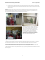
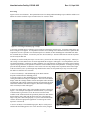
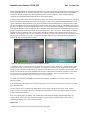
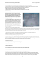
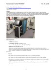
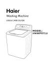
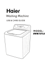
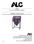
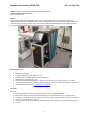
Nanofabrication Facility: PECVD SOP Rev. 01, Sept 2010 Author: Charlie Yao & Mario Beaudoin; Revision Mario Beaudoin Email: [email protected] Phone: 604-822-1853. Purpose This document outlines the standard operation for the Trion Plasma Enhanced Chemical Vapour Deposition (PECVD) device located in the AMPEL clean room. It is written with respect to typical usage and does not attempt to describe every operation available. It also describes basic failure mechanisms that may occur during operation. Only qualified users and superusers are allowed to operate this equipment. Relevant Literature TRION User's manual. J. Micromech. Microeng. 14 (2004) 317–323 Journal of Non-Crystalline Solids 338–340 (2004) 76–8 Materials Letters 54 (2002) 102–107 Robin Farnworth and Michael Musson, Optimization of Nanoporous Via-Hole Membranes for Micro Electro-Mechanical Systems (MEMS), Engineering Physics 479 project number 0460 under the supervision of M. Beaudoin. (Available at www.ampel.ubc.ca/nanofab). Procedure Foreword Be familiar with the reactants and products of the process by consulting the MSDS. Be familiar with safety warnings and alarms should a serious malfunction occur (i.e. major gas leak). In addition to the literature, consult a user who's familiar with the process intended. If none exist, consult a superuser should he have any concerns. In the event of a system crash where the 'Manual Recovery Panel' appears, refer to the end of this SOP on recovery. 1 Nanofabrication Facility: PECVD SOP Rev. 01, Sept 2010 The PECVD uses a combination touch screen and keyboard interface. Most operations are conducted with the touch screen and any occurrence of operation in this guide will be in reference to the touch screen unless otherwise noted. Start Up 1. Before entering the clean room, the gasses used for an intended process must be turned on from the master valves located in the cleanroom chase area. Access from room 444. All of the gasses, except ammonia, are in large cylinders located against the clean room wall adjacent to the PECVD: cabinet with its own main valve. Ammonia is stored in the vented gas cabinet next to the cylinders. Each gas is turned on from either a main valve (metallic knob) on the cylinder itself and/or from exit valves on the downstream side of the pressure regulators: Carbon Tetrafluoride (CF4), Oxygen (O2), Nitrogen (N2) and Nitrous Oxide (N2O) are accessed in this manner. Nitrogen should always be on for any process. Ammonia (NH3) can be turned on inside the vented Figure 2: Gas distribution system. 2. The DES is opened inside the cleanroom in the black gas distribution cabinet in back of the unit. It is the green valve and should be found delicately closed. Open it COUNTER CLOCKWISE. This is shown on Figure 3. 3. If CF4 is being used for your process, check that the release valve is closed and the toggle valve is open. They should be located behind the PECVD and are a pair of brass valves connecting white 1/4” tubes. 4. When entering the cleanroom, the system should be ready to go and an operational main menu should be visible as shown on Figure 4. 2 Nanofabrication Facility: PECVD SOP Rev. 01, Sept 2010 Figure 3 : Di-ethyl silane (DES) cabinet and bottle. At this point, the carbon disc should still be in the growth chamber and the arm retracted in the loadlock – verify by looking through the glass port of the lid to the load-lock. The 'Unload Wafer' button should be displayed. If this is not the case, please refer to the manual recovery section at the end of this document. This button will disappear and a 'Load Wafer' button will appear in the middle-left when the carbon disc is in the load-lock. Should the disc be on the arm and the 'Load Wafer' button be present rather than the 'Unload Wafer', it implies a previous user did not shut down the system properly and is unnecessarily putting stress on the robotic arm. Your process may continue as normal although the first few steps in processing will not be applicable. Instead, please refer to the manual recovery section. Figure 4 : PECVD main panel. Press the Unload Wafer button. This will take the graphite susceptor out of the process chamber and into the loadlock. The load-lock will then vent to atmosphere and you will be able to open the hatch to put your sample on the susceptor (see Figure 5). Close the hatch and hit the Load Wafer button to evacuate the load-lock and insert your sample in the process chamber. Figure 5 : Wafer (un)loading panels. 3 Nanofabrication Facility: PECVD SOP Rev. 01, Sept 2010 Processing Figure 4 shows several buttons. The topmost buttons are for editing and downloading recipes while the middle set of buttons are used to run those recipes in either manual or automatic mode. Figure 6 : Choosing and modiifying a recipe. 1. Press the 'Load/Edit Recipes' button to open a menu for selecting the desired recipe. A window similar to the one shown in Figure 6 will appear. It is important to load the correct settings first to allow the PECVD to equilibrate the temperature as soon as possible. Once the desired process is loaded, its name should appear in the blank area under the 'Load/Edit Recipes' button. You need to press the „Download Recipe’ button to make this the current recipe that will be run by the PECVD. 2. Should you wish to modify this recipe or create a new, you need to do so before proceeding to step 3. When you edit a recipe, a screen similar to the one on the right hand side of Figure 6 will appear. For each parameter, there are two displayed numbers: a parameter set and a parameter read. The parameter set displays the current value which the system is trying to achieve; the parameter read is the current measured value of the parameter. To change any setting, press the desired parameter set and enter in new values. The next step and previous step buttons at the bottom right of the screen allow you to cycle through steps and define the values for each parameter per step. You can save the file under a its old name or a new name. 3. Press 'Unload Wafer'. This should bring up the 'Wafer Unload Sequence' and describe the unloading process as it occurs (Figure 5). The unloading process will finish with nitrogen venting the load-lock to bring it to atmosphere. The LCD screen should display when the exchange chamber reaches atmosphere and it should be accompanied with a hissing sound from the lid. Open the lid at this point and hit OK. When the main menu reappears, this button will disappear and a 'Load Wafer' button will appear. 4. Place your sample in the center of the graphite susceptor as shown on Figure 7. The susceptor is designed for 100 mm wafers, if your sample is much smaller, a good trick is to use the cleaved 100 mm wafers available in the cleanroom shelf and specifically marked for PECVD use. Ensure that the disk is flush with the back of the arm. Check that the large O-ring seal is still seated properly. If you are concerned about the vacuum, discuss the appropriate application of vacuum grease with a superuser. Close the lid. 5. Press 'Load Wafer'. This should bring up the 'Wafer Load Sequence' and describe the loading process as it occurs. Be aware of any irregular 4 Figure 7 : Load-lock. Nanofabrication Facility: PECVD SOP Rev. 01, Sept 2010 sounds that might indicate an improper seal on the lid. Press 'Cancel' on the process should any reverberating sound occurs that might indicate an overtaxed pumping motor. Check the seating and lubrication of the O-ring and the action of the lid and repeat this step. Should problems persist, contact a superuser. Under normal operating conditions, the load-lock should reach 1000 mTorr in less than a minute. 6. Recipes can be run in either manual or automatic modes. For manual, press 'Manual Process Control' to bring up the process control menu shown on the left screen of Figure 8. Once you are satisfied with the parameters, let the system equilibrate to those parameters. First, allow the chuck to reach the temperature specified. The time for this can vary from about an hour when heating up the chuck, to hours for cool down. NB: the temperature read is that of the chuck, the graphite susceptor itself will require some time to reach the same temperature. The 2 leftmost buttons at the bottom should be lit (green) while the other 2 should be unlit. Press on the Gases Off button and wait for the pressure to equilibrate. Then, press on RF Off to ignite the plasma. The Process Time Read indicator should start counting up and you should be able to see the plasma through the window on the right hand side of the process chamber. NB: In manual mode, the time will NOT stop at the Process Time Set: you must hit the RF On button to kill the plasma at the desired process time. If your recipe has more than one step, you may press the right arrow to increase the step # and perform the next step. Figure 8 : Manual and Automatic process control screens. 7. Automatic control. You may also elect to run recipes in automatic mode. In that case, you need to have made sure that all the steps in your recipe are compatible. For instance, in automatic mode, the PECVD verifies if the process pressure and process temperatures are within preset tolerances; if not, the step will not be performed. You will see a screen like the one on the right hand side of Figure 8 that indicates the current step status. In this mode, the process runs for your preset time until all steps have been completed. This mode should only be used by experienced users performing long processes as it is rather capricious. 8. Record your parameters and sample information in the logbook (red binder) as necessary. Refer to previous entries as a guide. 9. In manual mode, once all steps have been processed, press “Pressure on' and 'Vacuum on'. Press 'Exit' to return the to the 'Main Menu'. 10. Once exited, you are returned to the 'Main Menu'. Let the chuck cool down as necessary. Press 'Unload Wafer' to remove your sample. Remove your sample once the load-lock reaches atmosphere. Repeat the process steps as many times as needed. Note: it is possible and is not unlikely with a small sample that during the loading and unloading stages, the sample will flip onto its other side. Again, the superuser suggests using a cleaved 100 mm wafer to create a small sample holding cavity to alleviate this problem. Shut Down 1. Make sure that the susceptor is flush with the loading fork guide. 5 Nanofabrication Facility: PECVD SOP Rev. 01, Sept 2010 2. Close the DES valve if you used it; please close DELICATELY! It closes CLOCKWISE. 3. Press 'Load Wafer'. The wafer is left inside the growth chamber to reduce the load on the robotic arm. It also helps if the next user wishes to preheat the susceptor before his/her growth/etch. 6. Make sure that the system properly makes it through its sequence. 7. Exit the clean room, enter the chase and turn off ammonia (NH3) if it was used. Manual Recovery In the event of a mechanical failure, or some other abnormal operation, it may be required to enter the maintenance mode. In this mode, the user can operate many of the individual steps that are normally all handled within a single process-step. The following outlines recovery of the robotic arm specifically in loading and unloading. 1. To open the Manual Recovery Panel directly, press 'Maintenance' in the main menu window. A keypad will pop up, prompting you to enter a password. The superuser should give the password to you when you get qualified to use the machine. After the password, press 'Manual Transport'. The Manual Recovery Panel will pop up by default if there's a malfunction in the device (Figure 9). Figure 9 : Manual recovery panel. 2. There is no set of steps that completely outlines what to do at any point: the machine may have crashed at any number of steps. What's important is to understand the steps the machine goes through, assess its current state and activate the necessary steps for recovery. The following list outlines normal operation with loading and unloading of the chuck: 1. The robotic arm is retracted, with the chuck on the arm and the lid down. The exchange chamber is at atmosphere, the main gate valve is closed and the pins are retracted. 2. Evacuate the exchange chamber by pressing 'load vacuum'. 3. Open the main gate valve. NB: the main gate valve should only be opened if the growth chamber and the load lock are at comparable pressures; for typical operation, the growth chamber is evacuated and the gate valve should only be opened if the load lock pressure is below 700 mTorr (note the m for millitorr). 4. Extend the robotic arm. 5. Lift the pins to lift the susceptor from the loading fork. 6. Retract the robotic arm. 7. Home the robotic arm. 8. Lower the pins to lower the susceptor in position on the growth chamber chuck. 9. Close the main gate valve. 10. Run processes. (Exit manual transport mode and proceed through main menu) 11. Raise the pins to raise the susceptor above the chuck. NB, otherwise, the loading arm would collide with the susceptor and push it against the back of the growth chamber; this would force an unwelcomed vent of the growth chamber and could also create damage to the forks, susceptor, chuck or other features in the growth chamber. 6 Nanofabrication Facility: PECVD SOP Rev. 01, Sept 2010 12. Make sure the load lock is under vacuum (i.e. 900 mTorr or less). 13. Open the main gate valve. 14. Extend the arm. 15. Lower the pins to lower the susceptor on the loading arm fork. 16. Retract the arm. 17. Home the arm. 18. Close the main gate valve. 19. Bring load-lock to atmosphere by pressing 'vent load'. It is up to the user to identify in which step the malfunction occurred and to identify the course of action given these normal sequence of steps. Note that manual operation does not change the main menu status. Thus, if the user manually loads the chuck and goes back to the main menu, it will still display 'Load Wafer' and not display 'Unload Wafer'. 7