1
Digital Systems Senior Design Project
ECE 477
Spring 2009
Using the UART peripheral library included with Microchip’s C32 compiler, we will send a byte
over the UART in the following manner (in C code):
WriteUART1(data);
So the library allows us to use easy-to-read syntax that appears to call a function, however the
function call is actually a #define, which will compile down to the identical machine code as the
assembly instruction.
#define WriteUART1(data)
U1TXREG = (data)
These libraries accomplish the tedious task of defining where in memory the peripheral control
registers are and providing intuitive interfaces to them. We will be using Microchip’s peripheral
code for both of our UARTs, SPI, and USB. Both UART modules will be operating with 8 data
bits, no parity, and one stop bit. The initialization will be as follows:
OpenUART1(UART_EN | UART_1STOPBIT,
UART_RX_ENABLE | UART_TX_ENABLE | UART_INT_RX_CHAR,
pbClk/16/DESIRED_BAUDRATE-1);
The initialization for each UART will be the same, however DESIRED_BAUDRATE will be
115200 for UART1 and 4800 for UART2. We will not be using any flow control. Our micro
controller will act as the master for the SPI. Our SPI chips can perform standard read operations
at 35 MHz, and all other operations at 75 MHz, so we will clock the SPI at 35 MHz [5]. The
PIC32 SPI module allows a frame mode
config = SPI_CON_MODE8|
// set SPI to send 8 bits at a time
SPI_CON_SMP|
// sample input at end of output(default)
SPI_CON_ON|
// SPI peripheral is enabled
SPI_CON_MSTEN;
// SPI configured as master
spi_channel = 1;
fpbClkDivider = 4;
// set clock to 35 MHz
SpiChnOpen(1, config, fpbClkDivider);
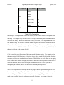
Peripheral
Pin Name
Pin Number
U1RX
51
U1TX
50
U2RX
31
U2TX
32
UART1
UART2
-4-