1
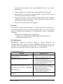
USER’S MANUAL
Rosetta-Lt
Data Translator
TM
IMPORTANT
Federal (USA) law restricts this device to sale by or on the order of a physician.
This instrument is to be used by authorized personnel only.
Responsibility for Information
It is the customer’s responsibility to ensure that the appropriate personnel within their
organization have access to this manual, including the safety information provided in
Section 1.
General Devices
1000 River St.
Ridgefield, NJ 07657
Phone: (201) 313-7075
Fax: (201) 313-5671
Internet: www.general-devices.com
Rosetta-Lt User’s Manual
Rosetta, Rosetta-Lt, Rosetta-Rx, CAREpoint,
GEMS, and GEMSCOM are trademarks of
General Devices.
LIFEPAK is a registered trademark of PhysioControl Corporation.
M Series & E Series are trademarks of ZOLL
Medical Corp.
HeartStart MRx is a trademark of Philips Medical
Systems.
Specifications subject to change without notice.
©April 2013 General Devices.
DOC 1848002 Rev N
ii
Table of Contents
Section 1 General Information
1.1 Safety Information ..................................................................................................... 1-1
1.2 Intended Use .............................................................................................................. 1-3
1.3 Glossary of Terms...................................................................................................... 1-3
1.4 Text Conventions ....................................................................................................... 1-3
1.5 Models and Versions ................................................................................................. 1-4
Section 2 Description
2.1 Physical Description .................................................................................................. 2-1
2.2 Controls, Indicators and Connectors ......................................................................... 2-1
Section 3 Connections
3.1 Battery and Power...................................................................................................... 3-1
3.2 Input (Monitor) .......................................................................................................... 3-1
3.3 Output (Communications) ......................................................................................... 3-1
Section 4 Operation
4.1 Getting Started ........................................................................................................... 4-1
4.2 Operating Instructions ............................................................................................... 4-1
4.3 Quick Guide ............................................................................................................... 4-5
Section 5 Maintenance, Test and Service
5.1 Maintenance............................................................................................................... 5-1
5.2 Testing ....................................................................................................................... 5-1
5.3 Updates ...................................................................................................................... 5-2
5.4 Troubleshooting ......................................................................................................... 5-2
5.5 Service and Repair ..................................................................................................... 5-3
5.6 Warranty Policy ......................................................................................................... 5-4
Section 6 Options, and Accessories
6.1 Options ....................................................................................................................... 6-1
6.2 Accessories ................................................................................................................ 6-1
Appendix A Specifications
A.1 Performance Specifications ...................................................................................... A-1
Appendix B Monitor/Defibrillator (Input) Device Information
B.1 Compatible Monitor/Defibrillators ........................................................................... B-1
B.2 Monitor Cables.......................................................................................................... B-1
B.3 Physio/Medtronic LIFEPAK 12/15 Configuration and Operation ........................... B-2
B.4 ZOLL M Series Configuration and Operation .......................................................... B-4
B.5 ZOLL E Series Configuration and Operation ........................................................... B-6
B.6 Philips HeartStart MRx Configuration and Operation ............................................. B-8
Appendix C Communications (Output) Device Information
C.1 Rosetta-Lt Radio/Phone (Output) Connection .......................................................... C-1
C.2 Compatible Communications Devices (Radios/Phones) .......................................... C-1
C.3 Radio/Phone Cable List ............................................................................................ C-2
C.4 Output Level Setting ................................................................................................. C-6
C.5 Using Rosetta-Lt with GEMSCOM Series 3000 Radios .......................................... C-7
Rosetta-Lt User’s Manual
iii
C.6 Schematic of Rosetta-Lt Radio/Phone Output ......................................................... C-8
Appendix D Receiving Equipment Information
D.1 Compatible Receiving Equipment ............................................................................ D-1
D.2 Sample (CAREpoint) Printouts ................................................................................ D-1
Appendix E Configuration Programming
E.1 Program Mode ........................................................................................................... E-1
E.2 Program Mode Operation (Versions 0.88 and later) ................................................. E-2
E.3 Program Mode Operation (Versions 0.82 – 0.86) ..................................................... E-3
E.4 Configuration Setting Programs ................................................................................ E-4
E.5 Clone Mode ............................................................................................................... E-7
E.6 Changing Configuration Settings Using a PC ........................................................... E-8
Rosetta-Lt User’s Manual
iv
Section 1
General Information
This manual provides descriptions, connection information, operating instructions as
well as maintenance and service information for the General Devices' Rosetta-Lt Data
Translator.
1.1 Safety Information
DO NOT OPERATE THIS EQUIPMENT WITHOUT
FIRST REVIEWING THIS SAFETY INFORMATION!
The following terms are used in this manual:
CAUTION:
Hazards or unsafe practices that may result in minor personal
injury, product or property damage.
WARNING:
Hazards or unsafe practices that may result in serious personal
injury or death.
CAUTIONS!
•
Before operation, read entire manual.
•
This device is to be used by authorized personnel only.
•
This device may require periodic maintenance to assure proper operation.
Refer to Section 5 for maintenance information.
•
Should the device appear to perform improperly, refer to Section 5 for test and
servicing information.
•
Do not connect or operate this device in any manner other than that specified
within this manual or any of the addendums included with this manual.
•
Before operation, check to insure that information is reliably transmitted over
the communications system you are using.
•
Depending upon transmission equipment and conditions, at times not all
information transmitted from the field may be received at the hospital.
Confirm receipt of the 12 lead report and its contents verbally.
WARNINGS!
•
Possible explosion hazard if used in the presence of flammable anesthetics or
gases.
•
Do not immerse in water or other fluids. Do not allow water or fluids to enter
case.
Rosetta-Lt User’s Manual
1-1
•
Do not connect the Rosetta-Lt or its cables into a landline telephone or network
circuit.
•
Do not attempt to connect the Rosetta-Lt or its cables into an AC power circuit.
GENERAL DEVICES AND ITS AGENTS ARE NOT RESPONSIBLE FOR ANY
DAMAGE OR CONSEQUENCES RESULTING FROM IMPROPER OR
UNAUTHORIZED USE OF THIS PRODUCT.
Rosetta-Lt User’s Manual
1-2
1.2 Intended Use
The intended use for the Rosetta-Lt is to provide a convenient, practical means to
facilitate the transmission of ECG and/or other physiologic information acquired from
a standard monitor/defibrillator in an EMS pre-hospital setting back to a physician at
hospital via standard communication means, such as 2-way radio, landline or wireless
telephone.
1.3 Glossary of Terms and Abbreviations
•
1 Volt Input/Output: Most field ECG monitors have a 1-Volt output jack. This
jack provides the ECG signal at 1-Volt/mV amplitude, typically Lead II or the lead
selected by the monitor. It is intended for connecting the monitor to devices such
as the Rosetta-Lt, which converts the signal into a format suitable for transmission
over radio, landline or cell phone.
•
FM: Frequency Modulation, a commonly used method of formatting information
for transmission by radio or telephone.
•
FSK: Frequency Shift Keying, a commonly used method of formatting data at
relatively low baud rates for transmission by radio or telephone.
•
DTMF: Dual Tone/Multi-Frequency is the technical name for “touch-tone” dialing
and is a commonly used method of signaling for transmission by radio or
telephone.
•
Acoustic Coupling: Acoustic coupling is a commonly used means of connecting an
audible signal from a speaker of a device (such as the Rosetta-Lt) to a microphone
on a radio or telephone handset by holding them in close proximity to one another
rather than by direct wire connection.
•
LP-12: LIFEPAK 12 monitor-defibrillator manufactured by Physio-Control
corporation of Redmond WA, USA.
•
LP-15: LIFEPAK 15 monitor-defibrillator manufactured by Physio-Control
corporation of Redmond WA, USA.
•
M Series: M Series monitor-defibrillator manufactured by ZOLL Medical
Corporation of Clemsford MA, USA.
•
E Series: E Series monitor-defibrillator manufactured by ZOLL Medical
Corporation of Clemsford MA, USA.
•
HeartStart MRx: HeartStart MRx monitor-defibrillator manufactured by Philips
Medical Systems of Andover MA, USA.
1.4 Text Conventions
Throughout this manual, special text characters are used to indicate controls, labels
and prompts.
•
Control, Indicator and Connector Labels: Italic letters such as Start/Stop
Rosetta-Lt User’s Manual
1-3
1.5 Models and Versions
Applicability
This manual describes all Rosetta-Lt features and functions available at time of
writing. Some of these features or functions described may not be provided by or
compatible with all Rosetta models or versions.
• This manual includes features and functionality through firmware version: 0.86
Models
• The Rosetta-Lt Model 7100 provides BOTH Single and 12-Lead ECG features.
• The Rosetta-Lt Model 7200 provides ONLY Single Lead ECG features.
Versions
The Rosetta-Lt contains software/firmware. Available features and functions may
vary with software/firmware version contained within the Rosetta-Lt.
• The Rosetta-Lt software/firmware is field upgradeable via the Rosetta
Programming Kit accessory.
• Refer to Section 5 for information on contacting General Devices’ Technical
Support for information on software/firmware features and updates.
Rosetta-Lt User’s Manual
1-4
Section 2
Product Description
This section describes the general features, specifications, controls, indicators, and
connectors for the Rosetta-Lt Data Translator. Drawings and photographs of the
Rosetta-Lt are provided in Figures 2-1, 2-2 and 2-3.
2.1 Description
The General Devices Rosetta family of products provides a means for communicating
physiologic information (waveforms and data) over standard communications means,
such as 2-way radio, landline or wireless (cellular) telephone, from a pre-hospital
location to a hospital.
The Rosetta-Lt is a compact, handheld device, which inputs single lead ECG from a
standard monitor/defibrillator or 12 lead ECG & summary data from a compatible
monitor (see Appendix B for compatible monitors devices) and “translates” or
converts this information to analog modulation and/or data formats suitable for
transmission over the available communications means to be received by a General
Devices’ CAREpoint EMS workstation, Rosetta-Rx receiving unit, or GEMS Series
2000 console (with Rosetta-Rx option) located at a hospital. It is intended to provide
distant health care professionals convenient access to such information to assist in
providing medical guidance as well as documentation for medical/legal purposes. The
Rosetta-Lt is powered by either internal 9V battery or by the monitor/defibrillator
(where compatible).
2.2 Controls, Indicators and Connectors
Controls
• Start/Stop button ............................. Powers unit on and Starts and stops
outputting of ECG/data to radio/phone.
Indicators
• Power LED ..................................... Solid Green indicates power is supplied by
monitor (external), Red indicates power is
supplied by internal battery, Blinking Red
indicates low battery.
• Tx/Rx LED ...................................... Blinking Green indicates unit is inputting
(receiving) 12L ECG/data from monitor,
Solid Green indicates unit has 12L
ECG/data stored in memory, Blinking Red
indicates unit is outputting 12L ECG/Data,
Blinking Amber indicates unit is outputting
single lead ECG.
Rosetta-Lt User’s Manual
2-1
• Speaker .......................................... Used for acoustic coupling as well as an
audible indicator.
Connectors
• Battery ............................................ 9V battery snap (internal)
• Monitor ........................................... Connection from monitor/defibrillator for
inputting ECG/Data & external power (RJ12
jack)
• Radio/Phone ................................... Connection to radio/phone for outputting
formatted ECG/Data (RJ45 jack)
TO XMTTR
TO MONITOR
Figure 2-1 Rosetta-Lt Dimensions
Rosetta-Lt User’s Manual
2-2
Figure 2-2 Rosetta-Lt Controls & Indicators
Figure 2-3 Rosetta-Lt Connectors
Rosetta-Lt User’s Manual
2-3
Section 3
Connections
This section contains generic information for connection of the Rosetta-Lt to provide
power (battery/external), input (monitoring) devices and output (communications)
devices. Additional connection information is provided in Appendix B & C.
3.1 Power (Battery & External)
Power connection for the Rosetta-Lt is provided by either an internal 9 Volt battery or,
from certain monitors externally, via the Monitor connector. Refer to Appendix B for
a list of monitors compatible of providing external power to Rosetta-Lt.
•
Battery connection is a standard 9V battery snap with leads, located within the
enclosure’s battery compartment. This connection is for a standard, user
replaceable, 9 Volt Alkaline Battery (Type NEDA 1604).
•
12VDC External power connection (where applicable) is provided via the Monitor
connector (see below).
3.2 Input
The Monitor connector is provided by the Rosetta-Lt for inputting ECG/Data and
power signals from a monitor/defibrillator. A monitor patch cable is used to provide
the direct “wired” connection. Refer to Appendix B for additional information on
compatibility and connections to monitor/defibrillator (input) devices.
•
For single lead ECG, a standard monitor’s 1 Volt ECG analog output connector is
connected to the Rosetta-Lt’s Monitor connector with an appropriate monitor
cable.
•
For 12 lead ECG/Data, the monitors serial data (RS-232) connector is connected
to the Rosetta-Lt’s Monitor connector with the appropriate cable.
3.3 Output
Output connections are provided by the Rosetta-Lt for outputting single lead or
formatted 12 lead ECG and summary data to a communications device (radio/cell
phone) for transmission. Output is provided either by the integral coupling speaker for
acoustic coupling or by the Radio/Phone connector for direct “wired” connection
(recommended). Refer to Appendix C for additional information on compatibility and
connection to communications (output) devices.
•
Direct (cable) output connection is provided by the Radio/Phone connector for
connection to the transmitting device (radio/phone) with a radio/phone patch cable.
This connector is a standard RJ-45 type. Contacts are provided for both output
audio (line and microphone levels) and a relay closure for PTT (Push-To-Talk)
functions for use with radios. The radio/phone patch cable can also determine the
Rosetta-Lt User’s Manual
3-1
modulation (standard or wide band) for single lead transmissions and switch the
acoustic coupling speaker. The direct connection output signal level is adjustable
to accommodate different radio/phone inputs. Refer to Appendix C for
information output level settings.
•
Acoustic coupling output connection is provided by the integral speaker.
Connection is accomplished by holding the microphone/mouthpiece of the
communications device (radio/phone) in close proximity to the speaker.
Note: Keep about a fingers width between the phone’s mouthpiece and Rosetta’s
speaker pad for best signal.
Rosetta-Lt User’s Manual
3-2
Section 4
Operation
This section contains operating information for the Rosetta-Lt. Refer to Sections 2 and
3 for additional description, and connection information and Appendix D-1 for a list of
equipment the Rosetta-Lt is intended to be used with.
4.1 Getting Started
The Rosetta-Lt is extremely easy to use and has only one control and a few indicators.
Sending / transmitting 12 lead reports via Rosetta-Lt is relatively simple but involves
several steps. Check that each of these steps is followed correctly to ensure 12 lead
reports are successfully transmitted from the field to the hospital:
Configuring the monitor for use with Rosetta-Lt (as needed)
Making connections between the Rosetta-Lt and the monitor
Configuring the radio/phone for use with Rosetta-Lt (as needed)
Making connections between the Rosetta-Lt and radio/phone
Acquiring a 12 lead with the monitor
Sending / transmitting the 12 lead from the monitor to the Rosetta-Lt
Sending / transmitting the 12 lead from the Rosetta-Lt via the radio/phone
Verifying reception verbally with the hospital
When setting up your system for the first time, be sure to follow the directions
closely. Test and verify operation before deploying the equipment to the full
department.
If you encounter difficulties, refer to the troubleshooting information in Section 5,
and if needed, contact General Devices’ Technical Support for assistance.
4.2 Operating Instructions
Power On/Off
There is no separate On/Off button. The Rosetta-Lt turns on after pressing the
Stop/Start button and automatically off after each use. The Rosetta-Lt can also
turn on automatically upon receiving 12 lead data from certain monitors (see
Appendix B). The power status is indicated by the Power LED.
•
Auto Turn-On Occurs
o After pressing Stop/Start button.
o After receiving data from certain compatible monitors.
•
Auto Turn-Off Occurs
o After the end of sending a single or 12 lead.
o After 20 seconds (configurable, see Appendix E) of no-use - if running on
battery (no auto turn-off if powered by the monitor)
o After clearing a stored 12 lead ECG.
Rosetta-Lt User’s Manual
4-1
•
Power LED
o Lights green if running on monitor (external) power.
o Lights red if running on battery.
o Blinks red if battery is low.
o Not lit if off.
Sending a Single Lead ECG “Strip”
Rosetta-Lt can send traditional single lead ECG “strips” when used with any
monitor/defibrillator that provides a 1V ECG output. Rosetta-Lt sends whatever
Lead is output by the monitor (real time), i.e. Lead II. To send a single lead strip:
•
Connect the 1-Volt ECG output of the monitor/defibrillator to the Monitor
connector of the Rosetta-Lt using the appropriate monitor patch cable (refer to
Appendix B for additional monitor connection information).
•
Connect the Rosetta-Lt to the communications device (radio/cell phone) (refer
to Appendix C for additional information) by either:
o Direct connection from the Radio/Phone connector to the radio or cell
phone using the appropriate radio/phone patch cable.
o Acoustic coupling from the Speaker to the radio/phone (direct connect
patch cable switch must not be connected).
Note: A single lead strip can only be sent if there is no 12 lead being input or
already stored in memory (Tx/Rx LED must be off). See instructions below
on clearing a stored 12 lead from memory.
•
When ready, press the Start/Stop button to power unit on. After pressing;
o Rosetta-Lt powers up (Power Led lit)
•
When ready, press the Start/Stop button again to begin sending.
pressing;
o Strip transmission begins
o Tx/Rx LED blinks Amber
o DTMF then FM tone will be played.
•
Sending stops;
After
Automatically after 20 seconds, or
If Start/Stop key is pressed again (before the 20 seconds are up)
o FM tone will stop and Strip transmission ends.
o Tx/Rx goes off
o Rosetta-Lt powers off
Sending a 12 lead ECG with Summary Data
Rosetta-Lt can send a formatted 12 lead and summary data when used with a
compatible and properly configured monitor/defibrillator. Refer to Appendix A &
B for additional monitor specific connection and configuration information.
Rosetta-Lt User’s Manual
4-2
After a 12 lead is acquired by the monitor from the patient, the sending of the 12
lead reports to the hospital is accomplished in three phases as described below.
• Reception:
Rosetta-Lt receives 12 lead file from the monitor (monitor
sends to Rosetta-Lt)
• Translation:
Rosetta-Lt translates the 12 lead file into a form suitable for
transmission by radio/phone.
• Sending:
Rosetta-Lt sends (transmits) the 12 lead via the radio/phone.
To send a 12 lead:
•
Connect the monitor’s serial/RS-232 data connector to the Monitor connector
of the Rosetta-Lt using the appropriate monitor patch cable
•
Press Start/Stop button to power the Rosetta-Lt (Power LED lit)
Note: This step is not necessary for monitors compatible with Rosetta-Lt’s
auto turn-on capability
•
When ready, transmit/send the 12 lead from the monitor to Rosetta-Lt:
Note: If the Rosetta-Lt must be powered on manually, the transmission from
the monitor must be started before the Lt automatically powers off.
•
Reception Phase begins upon receiving data from the monitor as follows:
o Tx/Rx LED blinks green
o Confirmation beeps are played on Speaker
If the transmission is canceled or contains errors
o Error sound is played
o Rosetta-Lt powers off
•
Translation Phase occurs after all the data is received from the monitor without
errors as follows:
o 12 lead is stored in memory
o Translation & formatting begins (approximately 15 seconds)
o Tx/Rx LED lights green
o Confirmation beeps are played on Speaker
The 12 lead is now ready to be sent from the Rosetta;
•
Disconnect the Rosetta-Lt from the monitor and move to a convenient location
for transmission.
•
Connect the Rosetta-Lt to the communication device (radio/cell phone) (refer
to Appendix C for additional information) by either:
o Direct connection from the Radio/Phone connector to the radio/phone using
the appropriate radio/cell phone patch cable.
o Or by acoustic coupling from the Speaker to the radio/phone.
•
Sending Phase begins after Pressing the Start/Stop button as follows:
Rosetta-Lt User’s Manual
4-3
Note: If the Rosetta-Lt was powered off, the first press of the Start/Stop
button will power the unit on, and a second press is required to begin
the sending phase.
o 12 lead (Rosetta transmission) sending begins
o Tx/Rx LED blinks red
o DTMF and FM tone will be played
•
At conclusion of 12 lead sending:
o FM tone will stop and 4 beeps are played
o Tx/Rx lights solid green (12 lead remains in memory)
o Rosetta-Lt powers off (if on battery power)
12 Lead Memory Storage
A 12 lead stored in memory will remain:
•
As long as unit is on – (if powered by the monitor) (Power lit green)
•
For approximately 20 minutes after the auto power-off or if power is lost due
to no or low battery.
•
Rosetta-Lt only holds one 12 lead in memory, the last one transferred to it.
Sending a 12 Lead from Memory after Power-Off
A 12 lead stored in memory while the unit is off can be sent by:
•
First “waking” (powering) the unit up by pressing the Start/Stop button once
o The unit will turn on and if there is a valid 12 lead in memory the unit will
give confirmation beeps and
o The Tx/Rx LED will be lit green.
Note: If no 12 lead is stored, the Tx/Rx LED will not be lit.
•
Then press the Start/Stop button again to begin sending.
Stopping a 12 Lead While Sending
The user can stop (cancel) sending a 12 lead by
•
Pressing the Start/Stop button.
o FM tone will stop and 4 beeps are played
Clearing a 12 Lead From Memory
The user can manually clear (erase) a 12 lead stored in memory by
•
Pressing and holding the Start/Stop button for 5 seconds.
acknowledges this as follows:
o Clear sound is played at the Speaker
o Tx/Rx LED goes off
o Unit powers off
Rosetta-Lt User’s Manual
The unit
4-4
4.3 Quick Guide
Sending a 12-Lead ECG Report
1) To acquire and transfer 12 Lead from Monitor to Rosetta-Lt:
• Connect the Rosetta-Lt to the monitor with the correct monitor cable
• Acquire a 12 Lead on the monitor or select one from memory
• Power on the Rosetta-Lt – (press Start/Stop once - Power LED will light)
Note: This step is automatic with the certain monitors
• Transmit/Send the 12 Lead from the monitor to the Rosetta-Lt 1
Note: See monitors User Manual for monitor specific details
o Tx/Rx LED will blink green while receiving the file
o Rosetta 12 lead is ready for transmission when the beeps stop and Tx/Rx
LED is lit (solid) green (indicating a 12 Lead is stored)
2) To transmit a 12 Lead from Rosetta-Lt to receive (hospital) end:
• Disconnect the Rosetta-Lt from the monitor and move to a convenient location
for transmission
• Connect to Radio or Cell Phone (either by patch cable or acoustic coupling)
• Make / Establish connection to receive hospital
o Radio - Set radio appropriate channel, or
o Phone – Dial appropriate phone number
o Verify a good “voice” connection to receive side
• If Rosetta-Lt is powered down, press Start/Stop button once to power unit on
o Verify Tx/Rx LED is lit (solid) green
• Press the Start/Stop button to begin the transmission
o Rosetta-Lt will transmit 12-Lead (tone will be audible and Tx/Rx LED will
blink green)
o When transmission is complete, tone will stop and Tx/Rx will light green
• Verbally verify reception of 12 Lead with receive end
Stopping or Re-Sending a 12 Lead
•
Press the Start/Stop button
o The Stop/Start button “toggles” the 12 Lead transmit operation
o The Stop/Start button “wakes” the unit after auto turn-off
Sending Single Lead ECG
•
Connect the Rosetta-Lt to the monitor’s 1Volt ECG jack with the appropriate
monitor Cable
•
Press the Start/Stop button
o Rosetta-Lt will transmit a 20 second strip
o When transmission is complete, Lt gives 4 beeps and Tx/Rx LED goes off
Notes: 1) Automatic transmission to the Lt depends on monitor type and configuration settings. Refer to
Appendix B for more information on monitor settings and operation.
Rosetta-Lt User’s Manual
4-5
Section 5
Maintenance, Test and Service
This section describes the maintenance, test and service aspects of the Rosetta-Lt.
5.1 Maintenance
The Rosetta-Lt requires no special maintenance other than periodic maintenance and
general cleaning.
Periodic Maintenance (PM)
Periodic maintenance is important to help prevent and identify possible
performance and operational discrepancies. The following periodic maintenance
should be performed at least once a year:
•
Inspect the device for physical damage or abuse that may require service.
•
Inspect the battery snaps & leads for fraying, cuts or damage that may require
service.
•
Inspect all patch cables for fraying, cuts or damage, replace as necessary.
•
Clean the enclosure as described below.
•
Test the 9V battery, replace if low or weak.
•
Perform Functional Testing as described in section 5.2 below.
Cleaning
•
The enclosure may be cleaned with a mild cleansing agent such as Windex.
•
DO NOT use any abrasive-cleaning agents, such as scouring powder.
•
DO NOT apply excessive liquid near openings where seepage may damage
internal components.
5.2 Testing
The Rosetta-Lt requires no special testing other than functional testing.
Functional Testing
Functional testing is intended to help identify possible performance and
operational discrepancies. Should testing reveal a possible discrepancy, refer to
the Troubleshooting Guide in this Section. If the discrepancy cannot be corrected,
immediately remove the device from service and refer to the Service and Repair
information in this section for information on how to obtain authorized service or
repair
Rosetta-Lt User’s Manual
5-1
•
Connect an ECG simulator to the monitor/defibrillator and set for a normal
sinus rhythm.
•
Connect the Rosetta-Lt to the monitor with the appropriate monitor cable.
•
Print the ECG on the monitor while transmitting a single lead ECG to the
receiving unit and print the received ECG.
•
Compare the monitor’s printout with the transmitted printout. The waveforms
shall match in both size and shape and the transmitted waveform shall not
contain excessive noise or distortion.
•
Repeat for 12-Lead transmission (if equipped).
5.3 Updates
The Rosetta-Lt contains software/firmware. Available features and functions may
vary with software/firmware version contained within the Rosetta-Lt. Contact General
Devices Tech Support for information on software/firmware versions, compatibility
and updates.
•
The Rosetta-Lt software/firmware is upgradeable:
o By the user in the field using the Rosetta Programming Kit and a PC.
o By the Factory during service.
5.4 Troubleshooting
IMPORTANT! Should the Rosetta-Lt appear to operate improperly, the
Troubleshooting Guide should be followed BEFORE contacting the factory for
assistance. This can significantly reduce the time to restore normal operation as the
procedure may immediately localize or identify the cause of the problem.
Troubleshooting Guide
Problem
Lt does not turn on when pressing
Stop/Start button
Transmits Single lead, not 12 lead
Transmission from monitor to Lt fails:
Lt does not receive 12-lead – Tx/Rx LED
not lighting green
Possible Cause
• Low battery
• Broken or damaged battery wires
• No 12-lead stored in Lt (see
Transmission from monitor to Lt fails)
• User pressing & holding Start/Stop
thereby erasing 12 Lead
• Rosetta not connected to monitor
• Rosetta not first powered On (ZOLL)
• Defective monitor cable
• Monitor improperly configured,
incompatible or defective.
continued
Rosetta-Lt User’s Manual
5-2
Transmitted ECG waveform noisy
Received 12 lead missing text data.
(Normal for Cellular or Satellite)
No transmission received at hospital
Received 12 lead missing Lead I
Acoustic coupling not working
• Noisy, weak or poor communications
coverage.
• Rosetta output level set too low *.
• Wrong or defective radio/phone cable.
• Noisy, weak or poor communications.
• Cellular or Satellite (normal).
• Rosetta output level set too high/low*
• Noisy, weak or poor communications.
• Rosetta output level set too high or
low (signal limited or over modulated
by radio) *.
• Incorrectly configured radio.
• Wrong/defective radio/phone cable.
• Problem at hospital / receive location.
• Rosetta output level set too high
(signal limited or over modulated by
radio) *
• Hospital (CAREpoint) receive level
setting too hot.
• Phone/Mic muffled into rubber pad
* Refer to Appendix C for information on how to set the Rosetta-Lt output level.
5.5 Service and Repair
The Rosetta-Lt Data Translator contains no serviceable parts. Interconnect cables are
prone to damage and may be repaired by any qualified electronic technician or
replaced. If, after following the General Troubleshooting guide, the problem can not
be corrected or it is determined that the Rosetta-Lt requires service, contact General
Devices and have the following information ready:
Model number
Serial number
Description of problem, be specific & include all symptoms and
conditions
Results of following the Troubleshooting Guide
Type of cell phone/radio used and type of connection
Type of monitor used and type of connection
Sample strips from the monitor/defibrillator and hospital receiving unit
Support/Service Hours:
Factory technical telephone support is provided during normal business hours
Monday through Friday, from 10:00 AM to 5:00 PM EST.
Rosetta-Lt User’s Manual
5-3
Twenty-Four (24) hour telephone service support may be provided for warranty or
extended warranty service at an additional cost where such services are available.
Direct factory services are NOT available beyond regular business hours.
Contact Information:
General Devices
1000 River St.
Ridgefield, NJ 07657
Attn: Service Department
Phone: (201) 313-7075
Fax: (201) 313-5671
e-mail: [email protected]
Internet: www.general-devices.com
Returning Materials To Factory
A Returned Materials Authorization number (RMA) must be obtained from the
service department and marked on the outside of any package to be sent to the
factory for service. Packages received without an RMA number may be rejected.
5.6 Warranty Policy
Items Covered by Warranty
The General Devices' Rosetta-Lt Data Translator is warranted against all defects in
parts and workmanship for one year from date of delivery. General Devices will
repair or replace any unit which it deems defective, provided it is within the
warranty period and proper use and maintenance procedures have been followed as
prescribed in this manual. The warranty provides replacement parts and labor,
F.O.B. Ridgefield, New Jersey.
Items Not Covered by Warranty
General Devices or its agents are not responsible for any problems related to nonGeneral Devices supplied equipment as well as connections to unauthorized
equipment. Items having failed due to mishandling, improper usage, improper
power source, lightning strikes or other natural disaster, fire, water damage, etc.,
are not covered by this warranty. Semi-annual and annual inspections are not
provided for under warranty.
Other Warranty Terms and Conditions
All warranty work is performed at the factory. Should service personnel be
requested on-site for a problem, the customer will be billed at the current rate for
such services.
Rosetta-Lt User’s Manual
5-4
No other party is authorized to make any other warranty, or to assume any liability
for General Devices’ products. No other warranty, either expressed or implied,
will be recognized.
Non-Warranty Service
Non-Warranty service is provided by General Devices at its current hourly rate
(contact factory for current service rates). Work performed on factory premises is
billed for actual bench time and materials, plus shipping and handling. Work
performed on customer premises is billed for time (portal-to-portal), travel
expenses and materials.
Rosetta-Lt User’s Manual
5-5
Section 6
Options and Accessories
This section describes options and accessories for the Rosetta-Lt.
6.1 Options
No options are available at the time of this printing.
6.2 Accessories
P/N LGRXPGMKT
Rosetta Programming Kit – for field firmware updates.
Note: Requires a PC with an available serial port (RS-232).
Rosetta-Lt User’s Manual
6-1
Appendix A
Specifications
This appendix provides additional information on specifications and performance.
A.1 Performance Specifications
12-Lead ECG 1
12L/Data Input .................................... Serial Data
Transfer/Translation time .................... 30 Sec. (nominal)
Transmission Time .............................. < 75 seconds (nominal)
Single Lead ECG
ECG Input ........................................... 1V (+/-2.5V)
Input Impedance .................................. >100 KΩ
Transmission Time .............................. 20 Seconds
Modulator
Output format ..................................... FM/FSK
Center Frequency ................................ 1400 +/- 5 Hz
Deviation ............................................. 12-Lead; 250 Hz/V,
Single Lead; 50 or 250 Hz/V (configurable)
Frequency Response ........................... DC to 150 Hz (+1, -3 dB) (diagnostic)
FSK ..................................................... 1.2/1.6 KHz
Controls & Indicators
Keys & Switches ................................. Start/Stop
Indicators ............................................. Tx/Rx, Power
Connections
Input jack (from monitor/defib) .......... RJ12; serial data, 12 VDC, 1V ECG
Output jack (to radio/cell phone) ........ RJ-45; FM/FSK (600 Ohm bal & Mic out),
PTT closure (switched ground)
Acoustic Coupler ................................ Integral Speaker
Power
External .............................................. 9-14 VDC, @ 130 mA draw
Internal Battery ................................... 9V, Alkaline, Type NEDA 1604 or equivalent
Mechanical
Size ...................................................... 6.25” x 3.75” x 1.40”
Weight ................................................. < 12 oz.
Environmental
Operating Temperature........................ 0 to +50 °C
Storage Temp ...................................... -20 to +60 °C
Humidity.............................................. 5 to 95%, non-condensing
Notes:
1. Compatible monitor models only.
2. Specifications subject to change without notice.
Rosetta-Lt User’s Manual
A-1
Appendix B
Monitor/Defibrillator
(Input) Device Information
Additional
This appendix provides additional information for use of the Rosetta-Lt Data Translator
with specific monitor defibrillator type input devices.
B.1 Compatible Monitor/Defibrillators
The following is a list of compatible monitors / features for use with Rosetta-Lt.
• Single Lead ECG:
o Any monitor/defibrillator with standard 1-Volt/mVolt output
• 12-Lead ECG/Summary Data:
o Medtronic/Physio Control LIFEPAK 12/15
o ZOLL M Series (with RS-232 port)
o ZOLL E Series
o Philips HeartStart MRx (with B11 option) – Also provides vital signs data
• External DC power to Rosetta-Lt:
o Medtronic/Physio Control LIFEPAK 12/15
B.2 Monitor Cables
The following is a list of cables available at time of this writing. Contact General
Devices for the most current information on monitor cables.
• P/N 034-184-011A - Monitor Cable, LP-12/15, System connector (Single Lead
and 12-Lead), LP-11 (Single Lead only)
• P/N 034-184-012A - Monitor Cable, LP5, Others, Standard 1 Volt ECG
output, 3.5mm Mono plug (Single Lead only)
• P/N 034-184-013A - Monitor Cable, LP-10, System Conn. (Single Lead only)
• P/N 034-184-014A - Monitor Cable, LP-20, Output Conn. (Single Lead only)
• P/N 034-184-015A - Monitor Cable, Philips MRx, 1 Volt ECG output, ¼”
Mono plug (Single Lead only)
• P/N 034-184-016A - Monitor Cable, M Series, E Series, RS232 / ECG output,
3.5mm 4-conductor plug (Single & 12 Lead)
• P/N 034-184-017A - Monitor Cable, Philips MRx, Serial RS-232 (12 Lead
only)
Rosetta-Lt User’s Manual
B-1
B.3 Physio/Medtronic LIFEPAK 12/15 Configuration and Operation
Configuration instructions for the LP-12/15 for use with the Rosetta-Lt 1:
• Enter the setup menu; by pressing and holding the OPTIONS key and the
EVENT key, while turning the unit ON.
• Enter setup mode Pass Code (typically “0000”) to get to the Setup Menu
• Setup Menu:
o
•
o
•
Select Sites…
•
Transmission/Data/Sites Menu:
•
Transmission/Data/Sites/”name” Menu:
o
o
o
•
o
o
•
Select Default Site 2
Set to ROSETTA
Select Default Report 2
Set to 12-Lead
Select Ports…3
Select Direct Connect…3
Transmission/Data/Ports/Direct Connect Menu: 3
o
•
Select Name
Set the name for this site as ”ROSETTA”
Select Output Port
Set to Direct Connect
Transmission/Data/Ports Menu: 3
o
•
Select an unused (unnamed) Site (i.e. “Site 1…”)
Go back to the Transmission/Data4 Menu:
o
Select Baud Rate3
Set to 38400 3
Go back to the Transmission Menu: 3
o
Select Default3
Set to Data
2,3
•
Go back to the main Setup Menu (press Home Screen)
•
12-Lead Menu:
o
o
o
3.
4.
Select Data…3
Transmission/Data4 Menu:
o
1.
2.
Select Transmission…
Transmission Menu:
Select 12-Lead…
Select Auto Transmit 2
Set to Data for LP-12 or On for LP-15
Select Format
Set to 3-Channel Standard
Configuration settings may vary with LP-12/15 software version
These settings are optional, but are suggested (when they do no conflict with settings for other
transmission sites or devices), to simplify operation by minimizing the number of key presses
required on the LP-12/15.
On the LP-15, this setting does not exist. Proceed as though this step was completed
On the LP-15, there is no Transmission/Data menu. It is just the Transmission menu.
Rosetta-Lt User’s Manual
B-2
Transferring a 12 Lead to Rosetta-Lt from the LP-12/15:
•
Connection to LP-12/15 monitor
Connect the Rosetta-Lt to the monitor with the monitor cable as shown below;
o Telephone style connector to the Rosetta-Lt’s Monitor jack
o 3.5mm plug to the LP-12/15’s gray System jack
•
12-Lead Acquisition
Perform a 12-Lead acquisition as normal;
o Press 12-Lead
o Enter age, sex as prompted
•
Auto-Transmit enabled
With Auto-Transmit enabled in the configuration setup (recommended), no
extra steps are required to transmit the 12-Lead into the Rosetta-Lt (as long as
the Rosetta-Lt was already connected via the monitor cable prior to the monitor
transmitting).
•
Manual Transmission
With Auto-Transmit disabled (or to re-transmit a 12-Lead):
o Press the Transmit button
o Select the appropriate Report (if necessary)
o Select Send
•
Refer to Section 4 for instructions for sending from the Rosetta-Lt.
End
Rosetta-Lt User’s Manual
B-3
B.4 ZOLL M Series Configuration and Operation
Configuration instructions for the M Series for use with Rosetta-Lt:
Note: The M Series monitor must have the “RS-232” serial/ECG port and it is
recommended to have software version “38.50” or newer to ensure
compatibility. Contact your ZOLL representative for information on
obtaining software updates.
•
Required settings:
o
o
o
o
•
Upload Baud Rate - 38400
Enable Data Relay 4 - Yes
1
12 Lead Frequency Response - 0.05-150Hz 4x3
2
AUTO TRANSMIT AFTER 12 LEAD – Yes
Entering System Configuration 3
After the monitor has been off for 10 seconds or more;
o Simultaneously press and hold the rightmost and leftmost softkeys.
o Turn the selector switch to MONITOR or ON (softkeys still pressed).
o Continuing to hold the buttons depressed until the configuration screen appears.
•
Enter Passcode
Enter the Passcode (typically 00000000).
o Press the 0 (zero) softkey. This will move the highlight to the next digit.
o Repeatedly press the 0 (zero) softkey until all eight digits have been entered.
o Note: If the Passcode was changed from the default, enter the new code instead.
o The Configuration Passcode screen will then automatically advance to the Select
Language menu.
o Press the Enter softkey to select the highlighted language (ENGLISH) to move to the
main configuration menu.
•
Changing Settings
o
o
Press the Change Config softkey to display the first configuration option menu.
Note: There are only three user configurable features available within each option
menu/screen.
Keep pressing Next Item softkey until you reach each of the features listed in the table
below. Once the desired line is highlighted, press the Change Value softkey to change
the setting to match the values from the table below.
Feature
ENABLE DATA RELAY 4
AUTO TRANSMIT AFTER 12 LEAD
UPLOAD BAUD RATE
12 LEAD FREQ RESPONSE
o
Setting
Yes
Yes 2
38400 bps
0.05-150Hz 4x3
After configuring the required settings, press the Exit Config softkey to display the
save/exit menu.
Rosetta-Lt User’s Manual
B-4
Transferring a 12 Lead to Rosetta-Lt from the M Series:
•
Connection to the M Series
Connect the Rosetta-Lt to the monitor with the monitor cable as shown below;
o Telephone style connector to the Rosetta-Lt’s Monitor jack
o 3.5mm plug to the M Series’ ECG x1000 RS-232 jack
Note: M Series monitor utilizes “soft key” controls associated with on-screen menus. The following
instructions assume familiarity with the monitors operation. Refer to M Series user
instructions for more info.
•
12-Lead Acquisition
Perform a 12 lead acquisition as normal;
o Press 12 Lead
o Press Acquire
o After acquisition, the Transmission Setup screen will appear and Data Relay will be
selected (if configured properly)
•
Power ON Rosetta-Lt
o
•
Transfer 12 Lead to Rosetta-Lt
o
•
Press Start/Stop on the Rosetta-Lt once
Note: The Rosetta-Lt stays on for approximately 20 seconds after a manual turn-on
(Power LED lit). If the monitor does not begin transmitting data during that
period, the Rosetta will power down and will have to be turned on again.
This step is not required for M Series monitors equipped with the Bluetooth
option, as these will automatically power the Rosetta-Lt on.
Press Dial Phone # (no phone number is required)
Rosetta-Lt will beep and Tx/Rx LED will blink green as data is transferred. The
transmission to Rosetta takes about 15 seconds.
When transfer is complete, the beeping will stop and Tx/Rx LED will light solid green.
Transmission of a 12 lead from Patient Records
With Auto-Transmit disabled or to transmit a 12 lead from records:
o Press 12 Lead
o Press Pt Info
o Press Patient Records
o Select the desired record
o Press Transmit
• Refer to Section 4 for instructions for sending from the Rosetta-Lt.
End.
Rosetta-Lt User’s Manual
B-5
B.5 ZOLL E Series Configuration and Operation
Configuration instructions for the E Series for use with Rosetta-Lt:
Note: It is recommended that E Series monitors have software version “1.01” or newer to ensure
compatibility. Contact your ZOLL representative to obtain software updates.
•
Optional settings:
Monitors equipped with the Bluetooth option enabled require the ZDR Destination to be set for
each power on session/transmission to Rosetta.
o Contact your ZOLL representative for information on disabling the Bluetooth feature.
•
Required settings:
o
o
o
o
o
•
12 Lead Frequency Response 1 - 0.05-150Hz 4x3
Auto Transmit After 12 Lead – Yes 2
Upload Baud Rate - 38400
Enable Data Relay 4 – Yes
Enable RescueNet Link 5 – No
Entering System Configuration 3
After the monitor has been off for 10 seconds or more;
o Simultaneously press and hold the rightmost and leftmost softkeys.
o Turn the selector switch to MONITOR or ON (softkeys still pressed).
o Continuing to hold the buttons depressed until the Passcode screen appears
•
Enter Passcode
Enter the Passcode (typically 00000000).
o Press the 0 (zero) softkey. This will move the highlight to the next digit.
o Repeatedly press the 0 (zero) softkey until all eight digits have been entered.
o Note: If the Passcode was changed from the default, enter the new code instead.
o The Configuration Passcode screen will then automatically advance to the Select
Language menu.
o Press the Enter softkey to select the highlighted language (ENGLISH) to move to the
main configuration menu.
•
Changing Settings
o
o
o
o
o
o
o
o
o
o
o
o
o
o
o
o
o
Press the Change Config softkey to display the first configuration option menu
Press Next Item softkey to select 12 Lead Set/Review
Press Next Item softkey until 12 LEAD FREQ RESPONSE is highlighted
Press Change Value to select 0.05-150Hz 4x3
Press Next Item softkey until AUTO TRANSMIT AFTER 12 LEAD is highlighted
Press Change Value to select Yes
Press Return once to return to the System Configuration menu
Press Next Item softkey to select Communications Set/Review
Press Enter
Press Change Value to set Upload Baud Rate to 38400 bps
4
Press Next Item softkey to select Enable Data Relay
Press Change Value to select Yes
5
Press Next Item softkey to select Enable RescueNet Link
Press Change Value to select No
Press Return twice to return to the main menu
Press Exit Config
Select Save Changes and Exit
Rosetta-Lt User’s Manual
B-6
o
o
o
Press Enter
Select NO when asked to save the data to the card and press Enter
Power monitor off to complete configuration.
Transferring a 12 Lead to Rosetta-Lt from the E Series:
•
Connection to the E Series
Connect the Rosetta-Lt to the monitor with the monitor cable;
o Telephone style connector to the Rosetta-Lt’s Monitor jack
o 3.5mm plug to the E Series’ ECG x1000 RS-232 jack
Note: E Series monitor utilizes “soft key” controls associated with on-screen menus. The following
instructions assume familiarity with the monitors operation. Refer to E Series user
instructions for more info.
•
ZDR Destination
For E Series monitors with Bluetooth enabled, ZDR Dest must be set to ZDR RS-232 at each
power -up.
o Press Param (from the main menu)
o Press Select to select ZDR Dest 6,
o Press Enter
o Press ZDR RS-232 7
•
12-Lead Acquisition
Perform a 12 lead acquisition as normal;
o Press 12 Lead
o Press Acquire
o After acquisition, the Transmission Setup screen will appear and ZDR RS-232 7 will be
selected.
•
Power ON Rosetta-Lt
o
•
Press Start/Stop on the Rosetta-Lt once
Note: The Rosetta-Lt stays on for approximately 20 seconds after a manual turn-on
(Power LED lit). If the monitor does not begin transmitting data during that
period, the Rosetta will power down and will have to be turned on again.
Transfer 12 Lead to Rosetta-Lt
o
Press Xmit Now 8
Rosetta-Lt will beep and Tx/Rx LED will blink green as data is transferred. The
transmission to Rosetta takes about 15 seconds.
When transfer is complete, the beeping will stop and Tx/Rx LED will light solid green.
Rosetta-Lt User’s Manual
B-7
Transmission of a 12 lead from Patient Records
•
With Auto-Transmit disabled or to transmit a 12 lead from records:
o Press 12 Lead
o Press Pt Info
o Press Patient Records
o Select the desired record
o Press Transmit
Refer to Section 4 for instructions for sending from the Rosetta-Lt. End.
•
Notes:
1.
2.
3.
4.
5.
6.
7.
8.
Setting the 12 Lead frequency response to 0.05-150Hz is optional but is recommended as it
allows for receive side noise filtering (cleaner trace) for transmitted 12-Leads, but may give a
noisier trace on the monitor.
The AUTO TRANSMIT feature is not fully functional on software versions older than 1.01.
Configuration settings may vary with monitor software version.
Data Relay was previously called Interlink by ZOLL. Certain versions of software may still
call it Interlink. If Data Relay does not appear in the menus, look for Interlink instead.
RescueNet Link does not exist in older versions of software. If not listed, there is no need to
disable it. Proceed to next step.
ZDR Dest was previously called RT Dest by ZOLL. Certain versions of software may still
call it RT Dest. If ZDR Dest does not appear in the menus, look for RT Dest instead.
ZDR RS-232 was previously called RS-232 by ZOLL. Certain versions of software may still
call it RS-232. If ZDR RS-232 does not appear in the menus, look for RS-232 instead.
Xmit Now was previously listed as Dial Phone #. If you see Dial Phone #, select that; you do
not need to enter a phone number
Rosetta-Lt User’s Manual
B-8
B.6 Philips HeartStart MRx Configuration and Operation
Configuration instructions for the HeartStart MRx for use with Rosetta-Lt:
No user configuration settings are required. HeartStart MRx monitors equipped
with the Rosetta option are pre-configured.
Note: The HeartStart MRx must have software version 9.00 or newer with the
“B11 Rosetta-Lt Integration” option enabled to be compatible. Contact your
Philips representative to obtain software/option updates.
Rosetta-Lt User’s Manual
B-9
Transferring a 12 Lead with Vital Signs to Rosetta-Lt from the MRx:
•
Connection to the HeartStart MRx
Connect the Rosetta-Lt to the monitor with the monitor cable as shown below;
o Telephone style connector to the Rosetta-Lt’s Monitor jack
o D9 plug to the HeartStart MRx’s RS-232 jack
Note: The HeartStart MRx monitor utilizes “soft key” controls associated with on-screen menus.
The following instructions assume familiarity with the MRx monitors operation. Refer to
HeartStart MRx user instructions for more info.
•
12-Lead Acquisition
Perform a 12 lead acquisition
On the HeartStart MRx:
o Press 12 Lead
o Press Start Acquire
o Enter age & sex as necessary
o After Acquisition, and Analysis, wait for the summary information screen
to appear
•
Transfer (Send) 12 Lead to Rosetta-Lt
On the HeartStart MRx:
o Press Menu
The Main Menu will appear
o Select & press Send
The Send To menu will appear
o Select & press Rosetta-Lt
The connection and sending status will be displayed
Rosetta-Lt will beep and Tx/Rx LED will blink green as 12L and current vital
signs data is transferred. The transmission to Rosetta takes about 35 seconds.
When transfer is complete;
o Beeping will stop and
o Tx/Rx LED will light solid green
o Rosetta-Lt is now ready for transmission
•
Refer to Section 4 for instructions to send (transmit) from the Rosetta-Lt to the
hospital receiving equipment. End.
Rosetta-Lt User’s Manual
B-10
Appendix C
Communications
(Output) Device Information
This appendix provides additional information for use of the Rosetta-Lt Data Translator
with communications (radio/phone) devices.
C.1 Rosetta-Lt Radio/Phone (Output) Connection
•
For connection to communications devices, the Rosetta-Lt output connection
(Radio/Phone connector) provides the following:
o A PTT closure (switched ground) for keying radio equipment (with “front
porch” time).
o Line level (audio) balanced signal output 600 Ohm, transformer & AC
coupled.
o Microphone level (mic) 10K Ohm unbalanced signal output.
Refer to figure C-1 for a schematic of the Rosetta-Lt’s output circuit.
•
Cell phones typically use a cable that plugs into the phone’s headset jack.
•
Radios typically use a cable that plugs into the radio’s auxiliary input jack
(mobiles) or a headset/mic jack (portables).
•
Additionally, the Rosetta audio signal output (mic and line output) is settable to
one of four levels. It may be necessary to set this output level to properly drive
the radio/phone mic input circuit. Refer to Section C.4 (below) for instructions.
IMPORTANT! Overdriving the radio or phones mic circuit may “compress or
limit” the Rosetta’s audio signal and distort it such that it will
not be received/decoded properly at the hospital.
C.2 Compatible Communications Devices (Radios/Phones)
Generally, landline/cellular phones and radio systems used for EMS and Public Safety
systems that provide an “ANALOG voice channel”, will provide reliable transmission
of information from the Rosetta-Lt. It must be recognized that systems with poor
coverage may not provide reliable operation. In addition, the performance of digital
phones/radios varies widely with compression/CODEC type as well as other factors
such as distance to tower. Be sure to test all equipment prior to use to assess
performance.
Rosetta-Lt User’s Manual
C-1
The following guideline information can be used to identify compatible
communications devices for use with Rosetta-Lt:
•
The communications device/system must be able to pass:
o Analog “audio” (FM sub-carrier centered around 1400Hz)
o DTMF
o 300 Baud FSK
o Signal for a duration of 75 Seconds (minimum)
Note: Radios may need to have the “Talk Time-Out” setting programmed for
> 75 Seconds - the standard 1 minute timeout will truncate the end of
the 12 lead transmissions.
•
Landline Telephone: - Compatible (acoustic coupling only)
o Any landline (wired) telephone can be used via acoustic coupling – phone
mouthpiece over the Rosetta’s speaker
WARNING! Do not connect the Rosetta-Lt directly to a landline telephone
circuit.
•
Cellular Telephone:
o Analog cellular phone – Compatible (most networks are discontinued)
Cable connection
Acoustic Coupling
o iDEN or GSM (Nextel, ATT/Cingular, T-Mobile) system phones (headset
connection) – Compatible however, typically most text/summary data is not
received
Cable (headset) connection
Acoustic Coupling
o Other CDMA (Verizon, Sprint, AllTel) digital cellular phone – typically NOT
compatible
Note: Digital phones MUST be tested on the system to verify compatibility.
•
2-Way Radio (portable or mobile)
o Conventional Radio - Compatible (Analog – i.e. HEAR, MED Ch, etc)
Cable connection
Acoustic Coupling
o Trunked Radio – Compatible (with Analog voice channels)
Cable connection
Acoustic Coupling
o Digital Radio – (digital voice channels) typically NOT compatible
Note: Digital radios MUST be tested on the system to verify compatibility.
C.3 Radio/Phone Cables
Direct cable connection from the Rosetta-Lt to the communications device is the
preferred transmission method, as it is more reliable than acoustic coupling, and does
not tie up the user’s hands, during transmission.
Rosetta-Lt User’s Manual
C-2
Below are examples of common Radio/Phone cable connections:
Rosetta-Lt with 034-184-023A radio cable
(commonly used with radio adapters)
Motorola portable showing Accessory Port
and BDN6676 audio adapter
Motorola portable with BDN6676 audio adapter
Motorola portable/BDN6676 connected to
Rosetta-Lt with 034-184-023A radio cable
Motorola portable with Spk/Mic
(modified to add a Rosetta jack)
Modified Motorola Spk/Mic connected to RosettaLt with034-184-023A radio cable
Rosetta-Lt with 034-184-022A cell phone cable
(commonly used with cell phone headset jack)
Cell phone connected to Rosetta-Lt with 034-184022A cell phone cable
Rosetta-Lt User’s Manual
C-3
The following is a list of cables and adapters available at time of this writing.
Contact General Devices for the latest information on cables available.
Rosetta Radio/Phone Cables:
034-184-021A
Cell Phone/Line-Out (RJ-11) “White” (600 Ohm, xfmr coupled)
034-184-022A
Mic/Headset 2.5mm Stereo for Cell Phone headset jack “Yellow”
034-184-023A
Mic/PTT 3.5mm Stereo for use with 3.5mm adapter “Blue”
034-184-024A
Mic/PTT 3.5mm Stereo for Maguire adapter “Orange”
034-184-025A
DISCONTINUED
034-184-026A
Mic/PTT 3.5mm Mono “Red”
034-184-027A
Mic/PTT 2.5mm Mono “Green”
034-184-028A
Line-Out/PTT 3.5mm St. GEMSCOM w/Rosetta jack “Black”
034-184-029A
Line-Out/PTT RJ45 GEMSCOM AUX jack “Blue/Black”
034-184-030A
Mic/PTT 6-pin HRS for MT1000 (req. NTN5075) “Blue”
034-184-031A
Mic/PTT 6-pin HRS for Saber (req. NTN5213) “Violet”
034-184-032A
Discontinued
Radio Adapters: (requires a radio cable as noted)
NTN5075
Motorola NTN5075B, for MT1000 (req. 030A cable)
BDN6676
Motorola BDN6676D, for HT1000, MT/MTS2000 (023A)
BDN9717
Motorola BDN9717, for HT750/1250 (req. 023A cable)
NTN5213
Motorola NTN5213, for Saber (req. 031A cable)
035-184-051A
GD, Standard GX-3000, in-line (req. 023A)
035-184-052A
GD, Kenwood TK890 (aux conn) no cable req.
035-184-053A
Rosetta - V210046 MACOM/ER, M-PA Spk/Mic (req.023A)
035-184-054A
Rosetta - V210048 MACOM/ER, M-RK Spk/Mic (req.023A)
035-184-055A
Rosetta - MACOM/ER, Orion PTT-Mic (req.023A cable)
035-184-056A
Discontinued – use 063A
035-184-057A
GD, Motorola M1225 (aux conn) no cable req.
035-184-058A
GD, Kenwood TK 760/860 (aux conn) no cable req.
035-184-059A
GD, Kenwood TK 730/830 (aux conn) no cable req.
035-184-060A
GD, Vertex VX-3000 (aux conn)
035-184-061A
GD, Kenwood TK 380/480 (aux conn) (req. 030A cable)
035-184-062A
GD, Mot Astro/Spectra MIC w/Rosetta jack (req, 023A cable)
(HMN1080 mic w/rectangular connector)
035-184-062A-CS
Modify Customer Supplied Mic to 062A (req, 023A cable)
035-184-063A
GD, Motorola In-Line RJ45 Mic adapter (req 023A cable)
035-184-064A
Not Used - Reserved
035-184-065A
GD, Kenwood TK8150, Auxiliary connector
035-184-066A
GD, Rosetta, Universal Radio Mic Adapter
035-184-067A
GD, Motorola, Y- cable, MSC2000
035-184-068A
GD, Motorola, Spectra w/o Maguire Interface, DB15 Male
035-184-069A
GD, Ericcson/Orion 800 MHz, EDACS Trunking-D28MTX
035-184-070A
GD, Motorola MCS 2000 to Rosetta RX adapter
035-184-071A
GD, Motorola XTL1500/2500/5000 mobile radio Aux conn.
Recommended to use 062A (rect conn) or 075A (round conn)
035-184-072A
GD, Motorola LTS 2000 portable (use, 027A)
035-184-073A
GD, EF Johnson Mobile 5300
035-184-074A
GD, Special Cell Phone car kit Mic 3.5mm mono Interface
035-184-075A
GD, Mot XTL5000 MIC w/Rosetta jack (req. 023A cable)
(HMN1090 mic w/round connector)
035-184-075A-CS
Modify Customer Supplied Mic to 075A (req. 023A cable)
035-184-076A
GD, Motorola MT/MTS/XTS Portable Radio Mic
w/ Rosetta jack (req. 023A cable)
Rosetta-Lt User’s Manual
C-4
035-184-077A
035-184-078A
035-184-079A
035-184-080A
035-184-081A
035-184-082A
035-184-083A
035-184-084A
035-184-085A
Rosetta-Lt User’s Manual
GD, GE Phoenix SX, 4 Pin Mascon Mic connector
GD, Kenwood Mobile 5710 (use 082A)
GD, Motorola Maratrac 14 pin VIP connector
GD, Vertex 4207, HDB15 connector
GD, Kenwood TK7180 to RX Cable
GD, Kenwood TK5710 to Lt Cable
GD, Vertex VX6000 DB25 Aux Connector
GD, Mot Astro/Spectra MIC w/Rosetta jack (req, 023A cable)
(HMN1081 Digital Mic w/rectangular connector)
GD, M930 Cell Phone Car kit Mic (mini-Fit Jr.) Interface
C-5
C.4 Output Level Setting
The level of the Rosetta-Lt’s output (XMIT) signal for direct cable connection to a
radio/phone is adjustable (programmable) by dip switch setting (older firmware) or by
configuration programming settings. This adjustment allows the output level to be
optimized for the radio/phone’s (modulated) output if needed.
IMPORTANT! It may be necessary to set this output level to properly drive the
radio/phone mic input circuit to ensure the signal can be properly
received at the hospital.
•
•
Output set too high (Hot) may result in distortion and poor detection of incoming
12 leads on the receive side.
Output set too low a signal may result in noisy ECG trace or intermittent detection
of incoming 12 leads on the receive side.
Note: Consult your radio service provider if needed to check that the transmitted
Rosetta signal is “modulated” correctly. For 2-way radio use, it is recommended
to select the Rosetta output level setting that most closely sets the radio
(Rosetta) transmission for 80% deviation on the RF carrier (just slightly into
compression/limiting).
Output Level Setting Methods
Output Level Setting is accomplished either by manual DIP-Switch setting or
configuration setting depending on the unit’s firmware version.
• Newer units with firmware version 0.82 and later; refer to Appendix E
Configuration Programming (Program 2).
• Older units with firmware version 0.73 and prior; use DIP-Switch setting
(below)
• Contact General Devices Technical Support for assistance on determining the
firmware version or obtaining updates.
DIP Switch Level Setting (older units with firmware ver 0.73 and prior only)
There are two dip switches located inside the battery compartment, which
“program” the output level to one of four discrete settings:
• HIGH
• MED-HIGH (factory setting)
• MED
• LOW
Rosetta-Lt User’s Manual
C-6
A pictorial chart like the one below, is located on the battery cover door, and
shows the placement of dip switch 1 and 2 for each of the four level settings.
Adjusting the output (XMIT) level settings (older units with firmware version
0.73 and prior only)
• Remove the battery compartment cover (note the label in the inside of the
cover).
• Disconnect and remove the 9V battery (carefully).
• Locate the two dip switches visible in one corner of the battery compartment.
• Using a ball point pen or similar tool, slide DIP switch 1 and 2 to the desired
position as per the chart.
Note: A change in level setting only takes effect after a power off.
• Reconnect and install the 9V battery (be careful not to stretch or pinch the
wires).
• Reinstall the battery compartment cover.
• Test the transmission with the new setting and verify:
o 12 Lead is detected reliable at the receive end
o ECG waveform is present and clean (all leads)
o All summary data (text) is present (may not apply for cellular)
• Select the setting that gives the most reliable reception.
Refer to Section 5 for obtaining additional technical support on adjusting output
level settings.
C.5 Using Rosetta-Lt with GEMSCOM Series 3000 Radios
Rosetta-Lt can be used with the General Devices’ GEMSCOM Series 3000 EMS
radios in one of two ways:
1. By acoustic coupling – keying the handset and holding over the Rosetta speaker
while sending ECG, or
2. By direct “cable” connection from the Rosetta’s “Radio/Phone” jack to the
GEMSCOM’s by either:
• “Aux” RJ45 connector on the speaker grille (for models built prior to July
2001). Note - Requires factory modification and updated software to
implement this feature.
• GEMSCOM’s “Rosetta” connector on the connector panel (for models built
after July 2001)
Rosetta-Lt User’s Manual
C-7
C.6 Schematic of Rosetta-Lt Radio/Phone Output
Rosetta-Lt User’s Manual
C-8
Appendix D
Receiving Equipment Information
Additional
This appendix provides additional information regarding acquisition, communications
and receiving/presentation equipment that the Rosetta-Lt Data Translator is intended to
be used with.
D.1 Compatible Receiving Equipment
•
Single Receiving/Presentation Equipment:
o Rosetta-Rx Stand-Alone Receiver
o CAREpoint EMS Workstation
o GEMS Series 2000 Console
o Other EMS consoles (single lead only - standard 1400Hz, 50Hz/mV)
•
12 Lead Receiving/Presentation Equipment:
o CAREpoint EMS Workstation
o Rosetta-Rx Stand-Alone Receiver
o GEMS Series 2000 Console with Rosetta option
Contact General Devices for additional information on compatible equipment.
D.2 Sample Printouts
•
CAREpoint – from Philips MRx
•
CAREpoint – from ZOLL M / E Series
•
CAREpoint – from Physio LP12/15
Rosetta-Lt User’s Manual
D-1
Rosetta-Lt User’s Manual
D-2
Rosetta-Lt User’s Manual
D-3
Rosetta-Lt User’s Manual
D-4
Appendix E
Configuration Programming
Additional
This section describes how to set the user programmable configuration settings. The
correct program settings are required to match the communications hook up for proper
operation.
Note: Configuration Programming is applicable only for units with firmware version
0.82 and later.
E.1 Program Mode
To Enter Program Mode:
•
Make sure the unit is NOT connected to the monitor/defibrillator.
•
Remove the battery compartment cover.
•
Disconnect and remove the 9V battery (carefully).
•
Locate the two dip switches visible in one corner of the battery
compartment.
•
Using a ball point pen or similar tool, slide DIP switch 2 to the “Off”
position (towards the inside of the Rosetta-Lt).
•
Reconnect and install the 9V battery (be careful not to stretch or pinch the
wires).
•
Reinstall the battery compartment cover.
Rosetta-Lt User’s Manual
E-1
Determine Firmware Version
•
Press the Start/Stop button to turn the unit on in Program Mode.
•
If the Power LED:
o blinks red and then amber, you have firmware version 0.88 or later.
Refer to Section E.2 for an overview of how Program Mode
operates for these software versions.
o blinks red and then red again, you have firmware version 0.82 –
0.86. Refer to Section E.3 for an overview of how Program Mode
operates for these software versions.
o turns solid red, you have firmware version 0.73 or prior and
Configuration Programming is not applicable to your unit. Slide
DIP switch 2 back to its original setting and refer to Appendix C
Output Device Information, Section C.4 for information on
adjusting the output level setting.
To Exit Program Mode:
•
Ensure that you have configured all settings appropriately.
•
Remove the battery compartment cover.
•
Disconnect and remove the 9V battery (carefully).
•
Locate the two dip switches visible in one corner of the battery
compartment.
•
Using a ball point pen or similar tool, slide DIP switch 2 to the “On”
position (towards the outside of the Rosetta-Lt)
•
Reconnect and install the 9V battery (be careful not to stretch or pinch the
wires).
•
Reinstall the battery compartment cover.
E.2 Program Mode Operation (Versions 0.88 and later)
Overview
•
The current “Program” number is indicated by the Power LED blinking
amber.
o The number of amber blinks indicates the Program Number
Note: If the Power LED blinks red, refer to Section E.3 below.
Rosetta-Lt User’s Manual
E-2
•
The current “Program Setting” number is indicated by the Tx/Rx LED
blinking green.
o The number of green blinks indicates the Program Setting
•
While traversing through the Program and Setting numbers, the Setting will
wrap-around to the beginning after reaching the end.
Example: LED’s - Power = 2 amber blinks, Tx/Rx = 3 green blinks
Means - Program 2, Setting 3 (Output Level set for MED-HIGH)
•
Upon entering Program Mode, the current program will be Program 1 –
User Program Version.
•
A tone will be heard while the Start/Stop button is pressed.
Program Mode Operation
•
To select a Program, Tap the Start/Stop button until the desired “Program”
number is indicated by the Power LED.
•
To change the Setting for the currently selected program, Press and Hold
the Start/Stop button for 3 seconds to increment to the “Setting” number
indicated by the Tx/Rx LED, then release the button. Repeat as necessary
until the desired setting is obtained.
•
Refer to Section E.4 for a listing of Programs.
•
Configuration Settings can also be changed using a PC. Refer to Section
E.6 for more information.
E.3 Program Mode Operation (Versions 0.82 – 0.86)
Overview
•
The current “Program” number is indicated by the Power LED blinking
red.
o The number of red blinks indicates the Program Number
Note: If the Power LED blinks amber, refer to Section E.2 above.
•
The current “Program Setting” number is indicated by the Tx/Rx LED
blinking green.
o The number of green blinks indicates the Program Setting
•
While traversing through the Program and Setting numbers, the Setting will
wrap-around to the beginning after reaching the end.
Example: LED’s - Power = 2 red blinks, Tx/Rx = 3 green blinks
Means - Program 2, Setting 3 (Output Level set for MED-HIGH)
Rosetta-Lt User’s Manual
E-3
•
Upon entering Program Mode, the current program will be Program 1 –
User Program Version.
•
A tone will be heard while the Start/Stop button is pressed.
Program Mode Operation
•
To select a Program, Press and Hold the Start/Stop button until the desired
“Program” number is indicated by the Power LED, then release the button.
•
To change the Setting for the currently selected program, Tap the
Start/Stop button to increment to the “Setting” number indicated by the
Tx/Rx LED. Repeat as necessary until the desired setting is obtained.
•
Refer to Section E.4 for a listing of Programs.
E.4 Configuration Setting Programs
Program 1: Firmware Version .................... Power LED blinks 1 time
Program 1 will output the current firmware version number. The version consists
of one digit Major number and two Minor numbers in the format of X.YZ.
Note: Program 1 is for information purposes only and cannot be changed.
The unit beeps a low digit tone and then outputs X
The unit beeps a high digit tone and then outputs Y
The unit beeps a low digit tone and then outputs Z
Setting (Tx/Rx LED blinks Setting #)
0 Version number is zero
1-9 Version number is 1 – 9, respectively
Program 2: Output Signal Level ................. Power LED blinks 2 times
The Output Signal Level setting specifies the Output Level of the Rosetta-Lt as
described in Appendix C.
Setting
1
2
3
4
(Tx/Rx LED blinks setting #)
LOW (used only is rare instances)
MED (factory default, recommended for most systems)
MED-HIGH (use if MED is too low)
HIGH (used only is rare instances)
Program 3: Transmission Mode .................. Power LED blinks 3 times
The Transmission Mode setting sets the Rosetta-Lt Transmission Mode. This
should be left as default (0x) unless instructed otherwise by General Devices
technical support, as this setting must match the receiving equipments capabilities.
Rosetta-Lt User’s Manual
E-4
Setting (Tx/Rx LED blinks setting #)
1 Mode 0x (DTMF lead ID) (factory default, recommended if DTMFs pass)
2 Mode 1x (FM lead ID – use if DTMFs do not pass reliably)
3 Mode 2x (Special FSK - not compatible with all Rosetta-Rx/CAREpoint
receiving equipment)
Program 4: Auto Transmission .................. Power LED blinks 4 times
The Auto Transmission setting configures the Rosetta-Lt to begin transmitting;
after a manual button press (recommended setting) or automatically once a 12
Lead has been stored.
Setting (Tx/Rx LED blinks setting #)
1 Off (factory default, recommended)
2 On (only to used when the unit is always connected to the radio)
Program 5: Serial Baud Rate....................... Power LED blinks 5 times
The Serial Baud-Rate configures the baud rate speed of the Rosetta-Lt. This setting
must match the baud-rate of the Monitor/Defib or PC.
Setting (Tx/Rx LED blinks setting #)
1 38400 bps (factory default, recommended)
2 115200 bps
Program 6: Preamble Signal Time .............. Power LED blinks 6 times
The Preamble Signal Time setting specifies the length of the tone that the RosettaLt sends out in order to wake up the receiver.
Setting
1
2
3
4
(Tx/Rx LED blinks Setting #)
OFF
1 second
2 seconds (factory default, recommended)
3 seconds
Program 7: Auto Power-Off ........................ Power LED blinks 7 times
The Auto Power-Off setting specifies the number of seconds that will elapse
before the Rosetta-Lt will turn off (to extend battery life). This is only applicable
when operating on 9V battery power.
Setting (Tx/Rx LED blinks setting #)
1 20 seconds (factory default, recommended)
2 60 seconds
3 120 seconds
Rosetta-Lt User’s Manual
E-5
Program 8: TX Un-Key Off-Time ............... Power LED blinks 8 times
The TX Un-Key Off-Time setting sets the number seconds the Rosetta releases it’s
PTT closure to un-key the radio momentarily during transmission (occurs just after
12L waveforms @ 45 sec). This setting is desirable as a “work-around” for use
with radios that have a 1 minute talk-out-timer set.
Setting
1
2
3
4
(Tx/Rx LED blinks setting #)
OFF
1 second
2 seconds (factory default, recommended)
3 seconds
Note: The following programs vary with firmware version. Refer to Program 1 to
determine the version of your unit.
For Firmware Versions 0.82-0.85:
Program 9: Clone Mode .............................. Power LED blinks 9 times
The Clone Mode setting will put the Rosetta-Lt into Clone Mode. For more
information of Clone Mode, refer to section E.5
Setting (Tx/Rx LED color indicates setting)
RED
Master (or Slave Unit when initially connected to master)
AMBER
Cloning
GREEN
Slave Unit Cloned
For Firmware Versions 0.86 and later:
Program 9: Text Data Mode ....................... Power LED blinks 9 times
The Text Data Mode setting selects what interpretation/text data is sent after the
ECG waveforms
Setting (Tx/Rx LED blinks setting #)
1 No Text Data (fastest transmission, use if text data is not received reliably)
2 Age/Sex Data only (sends only age & sex data)
3
All Text Data sent (factory default, recommended if received reliably)
Program 10: Clone Mode ............................ Power LED blinks 10 times
The Clone Mode setting will put the Rosetta-Lt into Clone Mode. For more
information of Clone Mode, refer to Section E.5
Setting (Tx/Rx LED color indicates setting)
RED
Master (or Slave Unit when initially connected to master)
AMBER
Cloning
GREEN
Slave Unit Cloned
Rosetta-Lt User’s Manual
E-6
E.5 Clone Mode
Clone Mode allows the user to configure one Rosetta-Lt device, and then quickly
transfer these settings to other units. This process requires a special Cloning Cable
(034-183-019A) that can be obtained from General Devices.
Notes: The Rosetta units used in cloning must be of the same firmware version.
Contact General Devices for information on updating Rosetta firmware in the
field. The “MASTER” unit will be on for several minutes when in Clone mode.
Battery life may be reduced if several units are to be cloned. Start with a new
battery and replace as necessary.
To Use Clone Mode:
•
The unit that has the desired settings is referred to as the “MASTER”.
•
The unit that you would like to add these settings to is referred to as the
“SLAVE”.
•
Both units must be in “Program Mode” according to the settings in Section
E.1.
•
Put the “MASTER” into Clone Mode as specified by the Configuration
Setting Programs above. The Power LED will be blinking amber and the
Tx/Rx LED will be solid red. (Power LED will be blinking red for versions
0.82 – 0.86)
•
Connect the “MASTER” to the “SLAVE” using the Clone Cable (034-183019A)
•
The “SLAVE” will wake up and have a solid Red Power LED.
•
Soon, both the “MASTER” and “SLAVE” will have a solid Amber Tx/Rx
LED. This indicates that the cloning process is taking place. This is a very
short process and usually only takes a few seconds.
•
Finally, both the “MASTER” and “SLAVE” will have a blinking amber
Power LED, and a solid Green Tx/Rx LED. (Power LED will be blinking
red for versions 0.82 – 0.86)
•
Disconnect the Clone Cable from the “MASTER” and the “SLAVE”
•
The “SLAVE” unit can be taken out of “Program Mode” according to the
settings in Section E.1. It may now be used for normal operations.
•
The “MASTER” may be used to repeat this process as necessary to clone
additional units. When done, it can be taken out of “Program Mode”
according to the settings in Section E.1 and can be used for normal
operations.
Rosetta-Lt User’s Manual
E-7
E.6 Changing Configuration Settings Using a PC (Firmware versions 0.88 and
later only)
Configuration Settings can be changed from a PC using EZ-Set for Rosetta-Lt
Software. Refer to the “Changing Configurations Settings Using EZ-Set” Quick
Guide located in the Support Center section of www.general-devices.com.
Rosetta-Lt User’s Manual
E-8