1
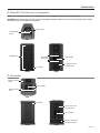
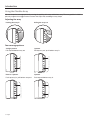
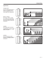
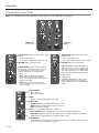
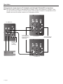
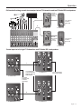
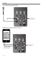
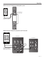
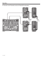
Operation F1 Subwoofer Control Panel Note: For a complete list of LED indications and behaviors, see “LED Indicators” on page 20. FRONT LED selector switch: • POWER enables LED to indicate power status. • LIMIT enables LED to indicate limiting. • OFF turns off LED. POWER/FAULT: indicates power/fault status • Blue = power on. • Red = fault condition. LIMIT: Amber = system limiting. SIGNAL/CLIP: Displays the input signal status in color. • Green = signal present. • Red = signal clipping - input signal too high. VOLUME – Adjusts subwoofer volume. Middle detent position is 0dB – nominal position when the F1 Model 812 and F1 Subwoofer are connected to a mixing console. Use 0dB position for a line-level signal input. LINE OUTPUT EQ: (See “Power On/Off Sequence” on page 12.) • THRU passes input signal to the output with no filtering. Recommended when using with F1 Model 812. • HPF passes input through a high-pass (100 Hz) filter. Affects LINE OUTPUT signals only. LINE OUTPUT 1 & 2: Individual outputs that provide balanced line output signals (pre-volume control) that can be sent to powered loudspeakers or a dditional s ubwoofers. Note: When the LINE OUTPUT EQ selector switch is set to THRU, the LINE OUTPUT signal will be full range. LINE INPUT 1 & 2: Combination XLR – ¼" phone connector inputs that accept line level signals. POLARITY: • NORM is used when when the F1 Model 812 loudspeaker is mounted on the supplied stand. • REV may be used to better align the bass when the subwoofer is located further away from the F1 Model 812 loudspeaker. AC input connector. POWER on/off switch. English - 11