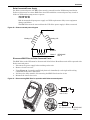
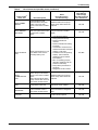
1
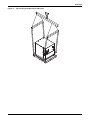
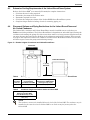
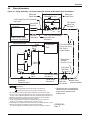
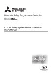
Liebert® EconoPhase™
User Manual - 85kW (24 Tons),125kW (35 Tons), 50Hz and 60Hz
TABLE OF CONTENTS
IMPORTANT SAFETY INSTRUCTIONS . . . . . . . . . . . . . . . . . . . . . . . . . . . . . . . . . . . . . . . . . .1
1.0
MODEL NUMBER NOMENCLATURE AND SPECIFICATIONS . . . . . . . . . . . . . . . . . . . . . . . . . . .3
2.0
LIEBERT DSE™ SYSTEM DESCRIPTION . . . . . . . . . . . . . . . . . . . . . . . . . . . . . . . . . . . . . . . .4
2.1
Liebert DSE . . . . . . . . . . . . . . . . . . . . . . . . . . . . . . . . . . . . . . . . . . . . . . . . . . . . . . . . . . . . . . . . 4
2.2
Liebert DSE™ . . . . . . . . . . . . . . . . . . . . . . . . . . . . . . . . . . . . . . . . . . . . . . . . . . . . . . . . . . . . . . . 5
2.3
Liebert MC™ . . . . . . . . . . . . . . . . . . . . . . . . . . . . . . . . . . . . . . . . . . . . . . . . . . . . . . . . . . . . . . . . 6
2.4
Liebert EconoPhase . . . . . . . . . . . . . . . . . . . . . . . . . . . . . . . . . . . . . . . . . . . . . . . . . . . . . . . . . . 7
2.5
Standard Air-Cooled System vs. Liebert EconoPhase System . . . . . . . . . . . . . . . . . . . . . . . . 8
2.6
Operating Modes . . . . . . . . . . . . . . . . . . . . . . . . . . . . . . . . . . . . . . . . . . . . . . . . . . . . . . . . . . . . 8
2.7
Module Communications . . . . . . . . . . . . . . . . . . . . . . . . . . . . . . . . . . . . . . . . . . . . . . . . . . . . . 10
3.0
DESCRIPTION OF LIEBERT ECONOPHASE OPERATION . . . . . . . . . . . . . . . . . . . . . . . . . . . .12
3.1
EconoPhase Control . . . . . . . . . . . . . . . . . . . . . . . . . . . . . . . . . . . . . . . . . . . . . . . . . . . . . . . . . 12
3.1.1
3.1.2
3.1.3
Room Temperature . . . . . . . . . . . . . . . . . . . . . . . . . . . . . . . . . . . . . . . . . . . . . . . . . . . . . . . . . . . 12
Refrigerant Temperature . . . . . . . . . . . . . . . . . . . . . . . . . . . . . . . . . . . . . . . . . . . . . . . . . . . . . . 14
Pump Pressure Differential . . . . . . . . . . . . . . . . . . . . . . . . . . . . . . . . . . . . . . . . . . . . . . . . . . . . 14
3.2
Pump Startup Routine . . . . . . . . . . . . . . . . . . . . . . . . . . . . . . . . . . . . . . . . . . . . . . . . . . . . . . . 14
3.3
Switch from Compressor Operation to Pump Operation . . . . . . . . . . . . . . . . . . . . . . . . . . . . 14
3.4
Switch from Pump Operation to Compressor Operation . . . . . . . . . . . . . . . . . . . . . . . . . . . . 15
3.5
Loop Temperatures . . . . . . . . . . . . . . . . . . . . . . . . . . . . . . . . . . . . . . . . . . . . . . . . . . . . . . . . . 15
3.6
Mechanical Considerations . . . . . . . . . . . . . . . . . . . . . . . . . . . . . . . . . . . . . . . . . . . . . . . . . . . 15
4.0
INSTALLATION . . . . . . . . . . . . . . . . . . . . . . . . . . . . . . . . . . . . . . . . . . . . . . . . . . . . . . . . . 16
4.1
Unpacking and Moving the Liebert EconoPhase . . . . . . . . . . . . . . . . . . . . . . . . . . . . . . . . . . 16
4.2
Liebert EconoPhase Dimensions and Weights . . . . . . . . . . . . . . . . . . . . . . . . . . . . . . . . . . . . 19
4.3
Determine Cooling Requirements of the Liebert EconoPhase System . . . . . . . . . . . . . . . . . 20
4.4
Placement Options and Piping Restrictions for the Liebert EconoPhase and Air-Cooled
Condenser . . . . . . . . . . . . . . . . . . . . . . . . . . . . . . . . . . . . . . . . . . . . . . . . . . . . . . . . . . . . . . . . . 20
4.5
Line Sizing in a Liebert EconoPhase System . . . . . . . . . . . . . . . . . . . . . . . . . . . . . . . . . . . . . 21
4.6
Piping Schematics . . . . . . . . . . . . . . . . . . . . . . . . . . . . . . . . . . . . . . . . . . . . . . . . . . . . . . . . . . 22
4.7
System Charging . . . . . . . . . . . . . . . . . . . . . . . . . . . . . . . . . . . . . . . . . . . . . . . . . . . . . . . . . . . 25
4.8
Electrical Connections . . . . . . . . . . . . . . . . . . . . . . . . . . . . . . . . . . . . . . . . . . . . . . . . . . . . . . . 26
4.8.1
5.0
Variable Speed Drive . . . . . . . . . . . . . . . . . . . . . . . . . . . . . . . . . . . . . . . . . . . . . . . . . . . . . . . . . 28
TROUBLESHOOTING . . . . . . . . . . . . . . . . . . . . . . . . . . . . . . . . . . . . . . . . . . . . . . . . . . . . . 30
i
FIGURES
Figure 1
Figure 2
Figure 3
Figure 4
Figure 5
Figure 6
Figure 7
Figure 8
Figure 9
Figure 10
Figure 11
Figure 12
Figure 13
Figure 14
Figure 15
Figure 16
Figure 17
Figure 18
Figure 19
Figure 20
Figure 21
Pressure enthalpy diagram, pumped refrigerant Liebert EconoPhase . . . . . . . . . . . . . . . . . . . . . . 4
Liebert DSE indoor unit . . . . . . . . . . . . . . . . . . . . . . . . . . . . . . . . . . . . . . . . . . . . . . . . . . . . . . . . . . . 5
Liebert MC™ air -cooled microchannel condenser . . . . . . . . . . . . . . . . . . . . . . . . . . . . . . . . . . . . . . 6
Liebert EconoPhase module . . . . . . . . . . . . . . . . . . . . . . . . . . . . . . . . . . . . . . . . . . . . . . . . . . . . . . . . 7
Compressorized operation flow path . . . . . . . . . . . . . . . . . . . . . . . . . . . . . . . . . . . . . . . . . . . . . . . . . 9
Pump operation flow path . . . . . . . . . . . . . . . . . . . . . . . . . . . . . . . . . . . . . . . . . . . . . . . . . . . . . . . . . 9
CANbus connections . . . . . . . . . . . . . . . . . . . . . . . . . . . . . . . . . . . . . . . . . . . . . . . . . . . . . . . . . . . . . 11
Two-circuit pump control . . . . . . . . . . . . . . . . . . . . . . . . . . . . . . . . . . . . . . . . . . . . . . . . . . . . . . . . . 13
Removing the shipping crate . . . . . . . . . . . . . . . . . . . . . . . . . . . . . . . . . . . . . . . . . . . . . . . . . . . . . . 17
Removing screws securing Liebert EconoPhase to skid . . . . . . . . . . . . . . . . . . . . . . . . . . . . . . . . . 17
Typical sling arrangement for lifting unit . . . . . . . . . . . . . . . . . . . . . . . . . . . . . . . . . . . . . . . . . . . . 18
Liebert EconoPhase typical unit dimensional drawing . . . . . . . . . . . . . . . . . . . . . . . . . . . . . . . . . 19
Relative heights of condenser and Liebert EconoPhase . . . . . . . . . . . . . . . . . . . . . . . . . . . . . . . . . 20
Piping Schematic—air-cooled Liebert DA 125/150 models with Liebert EconoPhase . . . . . . . . . 22
Piping Schematic—air-cooled Liebert DA 080/085 models with Liebert EconoPhase . . . . . . . . . 23
Typical unit arrangement diagram . . . . . . . . . . . . . . . . . . . . . . . . . . . . . . . . . . . . . . . . . . . . . . . . . 24
Typical general arrangement diagram . . . . . . . . . . . . . . . . . . . . . . . . . . . . . . . . . . . . . . . . . . . . . . 25
Typical field electrical connection . . . . . . . . . . . . . . . . . . . . . . . . . . . . . . . . . . . . . . . . . . . . . . . . . . 27
Wye-connected power diagram. . . . . . . . . . . . . . . . . . . . . . . . . . . . . . . . . . . . . . . . . . . . . . . . . . . . . 28
Delta-connected power diagram . . . . . . . . . . . . . . . . . . . . . . . . . . . . . . . . . . . . . . . . . . . . . . . . . . . . 29
Disconnecting EMC filter for operation with Delta-connected power . . . . . . . . . . . . . . . . . . . . . . 29
TABLES
Table 1
Table 2
Table 3
Table 4
Table 5
Table 6
Table 7
Table 8
Liebert EconoPhase specifications . . . . . . . . . . . . . . . . . . . . . . . . . . . . . . . . . . . . . . . . . . . . . . . . . . . 3
Description of events and actions in Figure 8 . . . . . . . . . . . . . . . . . . . . . . . . . . . . . . . . . . . . . . . . 13
Representative Liebert EconoPhase loop temperatures at 35°F (1.6°C) outdoor temperature . . 15
Field piping restrictions between air-cooled condenser and Liebert EconoPhase. . . . . . . . . . . . . 20
Condenser height restrictions relative to Liebert DSE . . . . . . . . . . . . . . . . . . . . . . . . . . . . . . . . . 20
Line sizing for Liebert DSE™ / Liebert EconoPhase System . . . . . . . . . . . . . . . . . . . . . . . . . . . . . 21
Liebert EconoPhase module charge . . . . . . . . . . . . . . . . . . . . . . . . . . . . . . . . . . . . . . . . . . . . . . . . . 25
List of alarms and possible causes . . . . . . . . . . . . . . . . . . . . . . . . . . . . . . . . . . . . . . . . . . . . . . . . . . 30
ii
IMPORTANT SAFETY INSTRUCTIONS
IMPORTANT SAFETY INSTRUCTIONS
SAVE THESE INSTRUCTIONS
This manual contains important safety instructions that must be followed during the installation and
maintenance of the Liebert EconoPhase Pumped Refrigerant Economizer. Read this manual
thoroughly before attempting to move, lift, remove packaging from, install, operate or perform
maintenance on this unit.
Only qualified personnel should move, lift, remove packaging from, install or service this equipment.
Adhere to all warnings, cautions and installation, operating and safety instructions on the unit and in
this manual. Follow all operating and user instructions.
! WARNING
Risk of electric shock. Can cause injury or death.
Open all local and remote electric power disconnect switches and verify that power is Off with
a voltmeter before working within the electrical connection enclosures or making any
electrical connections. Before proceeding with installation, read all instructions, verify that
all the parts are included and check the nameplate to be sure the voltage matches available
utility power. Follow all local codes.
! WARNING
Arc flash and electric shock hazard. Can cause injury or death.
Open all local and remote electric power disconnect switches, verify that power is Off with a
voltmeter and wear appropriate personal protective equipment per NFPA 70E before working
within the electrical control enclosure. Customer must provide earth ground to unit, per NEC,
CEC and local codes, as applicable. Before proceeding with installation, read all instructions,
verify that all the parts are included and check the nameplate to be sure the voltage matches
available utility power. Follow all appropriate national and local codes.
Reinstall all terminal covers before connecting power to the unit. Failure to install these
covers exposes high-voltage terminals.
! WARNING
Risk of electric shock from leakage current. Can cause injury or death.
Reconnect earth ground if servicing or replacing the variable speed drive (VSD).
! WARNING
Risk of explosive discharge from high-pressure refrigerant. Can cause injury or death.
This unit contains fluids and gases under high pressure. Relieve pressure before cutting into
or working with piping.
! WARNING
Risk of refrigerant system rupture or explosion. Can cause equipment damage, injury or
death.
Do not pressurize the refrigerant system higher than the Design Pressure rating marked on
the unit nameplate. Wear appropriate personal protective equipment and monitor the
pressure with accurately calibrated pressure gauges during the system charging operation.
For systems requiring EU CE compliance (50Hz), the system installer must provide and
install a discharge pressure relief valve rated for a maximum of 650 psig (45 bar) in the high
side refrigerant circuit. The pressure relief valve must be CE-certified to the EU Pressure
Equipment Directive by an EU “Notified Body.”
! WARNING
Risk of improper wiring, piping, moving, lifting and handling. Can cause equipment damage,
injury or death.
Installation and service of this equipment should be done only by qualified personnel who
have been specially trained in the installation of Emerson Thermal Management equipment.
Liebert® EconoPhase™
1
IMPORTANT SAFETY INSTRUCTIONS
! CAUTION
Risk of handling heavy unit and component parts. Can cause injury and equipment damage.
Use OSHA recommended safe lifting techniques and/or lifting equipment rated for the weight
of the unit. See Table 1 of this manual for unit weight.
! CAUTION
Risk of contact with hot surfaces. Can cause injury.
The pumps and refrigerant discharge lines are extremely hot during unit operation. Allow
sufficient time for them to cool before working within the unit cabinet. Use extreme caution
and wear protective gloves and arm protection when working on or near hot pumps and
refrigerant lines.
!
CAUTION
Risk of sharp edges, splinters and exposed fasteners. Can cause injury.
Only properly trained and qualified personnel wearing appropriate safety headgear, gloves,
shoes and glasses should attempt to move, lift or remove packaging from the unit.
! CAUTION
Risk of electric shock and short circuits. Can cause equipment damage, injury or death.
Insert CSA certified or UL listed bushings into holes and or knockouts used to route wiring
through to protect the wire insulation from contact with sheet metal edges.
NOTICE
Risk of excessive oxidation and scale formation on interior piping surfaces. Can cause
equipment damage.
During brazing, the refrigerant lines must be filled with flowing dry nitrogen to prevent
excessive oxidation and scale formation inside the piping. Use currently documented and
accepted good refrigeration practices for piping supports, leak testing, dehydration and
charging. Failure to use good system practices may result in damage to the system. Refer to
the most currently published ASHRAE refrigeration handbook for documented good practice
refrigeration piping guidelines.
NOTICE
Risk of improper electrical connection of three-phase input power. Can cause unit damage.
Service technicians should use a gauge set during the initial startup to verify that the
three-phase power is connected properly.
NOTICE
Risk of overheated terminals. Can cause wiring and component damage.
Use copper wiring only. Make sure that all connections are tight.
NOTICE
Risk of improper program adjustment. Can cause equipment damage and loss of warranty.
The VSD is factory-programmed for proper operation. Altering the VSD program without
authorization from the factory may void the warranty.
NOTICE
Risk of mismatched input power supply and VSD requirements. May cause equipment
damage and failure.
The EMC filter must be removed from the VSD if the power supply is Delta-connected.
NOTICE
Risk of improper forklift operation. Can cause equipment damage.
Keep the forklift’s tines level and at a height suitable to fit below the skid and/or unit to
prevent exterior and/or underside damage.
2
Liebert® EconoPhase™
Model Number Nomenclature and Specifications
1.0
MODEL NUMBER NOMENCLATURE AND SPECIFICATIONS
Example: PR125AA6DD-*
PR
125
A
Nominal Cooling
Capacity, kW
6
D
D
Pump
Configuration
S = Single
D = Dual
A = 460V, 60Hz
B = 575V, 60Hz
E = 416V, 3 Phase,
60Hz
G = 415V, 3 Phase,
50Hz
Y = 208/230V, 60Hz
2 = 380/400V, 3 Phase,
60Hz
Disconnect Switch,
Amperage
5 = 5,000 Amp SCCR
6 = 65,000 Amp SCCR
A = Air-Cooled
Heat Rejection
Liebert Pumped
Refrigerant
Economizer
System
Table 1
A
—
*
Placeholder
Packaging
D = Domestic
E = Export Crating
Revision
Level
Pump Motor
Weight, lb (kg)
Liebert EconoPhase specifications
Electrical Specifications
Voltage
Phase
Hz
FLA
Minimum
Supply
Circuit
Ampacity
PR125AA***
PR085AA***
460
3
60
7.0
7.9
15
1.6
3.5
340 (154)
478 (217)
PR125AY***
PR085AY***
208/230
3
60
13.8
15.5
20
1.6
6.9
340 (154)
478 (217)
575
3
60
5.6
6.3
15
1.6
3.5
390 (177)
528 (240)
PR125A2***
PR085A2***
380/400
3
60
8.4
9.4
15
1.6
3.5
390 (177)
528 (240)
PR125AG***
PR085AG***
415
3
50
7.4
8.3
15
1.6
3.7
347 (157)
578 (262)
Model
PR125AB***
PR085ABA***
FLA = Full Load Amps
Liebert® EconoPhase™
3
Maximum
Fuse Size
HP
FLA
Unit
Shipping
Liebert DSE™ System Description
2.0
LIEBERT DSE™ SYSTEM DESCRIPTION
2.1
Liebert DSE
Liebert DSE systems are designed to provide precision air conditioning to computer racks in a data
center or computer room as efficiently and effectively as possible.
A Liebert DSE system with Liebert EconoPhase is composed of:
• Liebert DSE—High efficiency, floor-mounted indoor unit
• Liebert MC™ Condenser—Air-cooled microchannel condenser, premium version
• Liebert EconoPhase—Liebert EconoPhase module
The Liebert EconoPhase is an add-on module for use with an air-cooled Liebert DSE system. The
Liebert EconoPhase will allow the system to switch to Liebert EconoPhase operation when the
outdoor temperature is low enough to provide the required temperature difference between the inside
air and the outside air, providing significant energy savings because there is no need to operate the
compressor. At lower temperatures, the system switches one or both circuits from Compressor Mode
to Pump Mode. The pump consumes roughly 1/10th of the power consumed by the compressor.
The Liebert EconoPhase system maintains this energy efficiency by employing the heat absorption
properties of a liquid (pumped refrigerant) through a phase change. Refrigerant is pumped as a
liquid, becomes a gas within the Liebert DSE evaporator and then is returned to the Liebert MC
where it condenses to a liquid. The subcooled liquid refrigerant from the condenser is then run
directly into the Liebert EconoPhase pumps and is circulated back to the Liebert DSE unit (see
Figure 1). The system will operate as a typical air-cooled direct expansion system when outdoor
ambient conditions are unfavorable to EconoPhase operation. The pumps in the Liebert EconoPhase
pump module are turned off and bypassed during compressor operation.
Figure 1
Pressure enthalpy diagram, pumped refrigerant Liebert EconoPhase
Liquid
Liquid/Vapor Mix
Vapor
Condenser (DX Mode)
Pressure
Indoor Unit
Condenser (Pump Mode)
Tradtional Vapor Compression Cycle
EconoPhase Cycle
Enthalpy
4
Liebert® EconoPhase™
Liebert DSE™ System Description
2.2
Liebert DSE™
The Liebert DSE indoor unit (Figure 2) is a high-efficiency room-based Precision Cooling module
designed to provide the airflow, air temperature and humidity required for reliable data center
operation. Components contributing to the high-efficiency operation include Liebert iCOM®
monitoring and control system, tandem scroll compressors, fin-and-tube evaporator coil, variable
speed EC plug fans and electronic expansion valves. The Liebert DSE exceeds ASHRAE 90.1
standards for energy efficiency.
Figure 2
Liebert DSE indoor unit
Liebert® EconoPhase™
5
Liebert DSE™ System Description
2.3
Liebert MC™
The Liebert MC air-cooled microchannel condenser (Figure 3) is a low-profile, direct-drive propeller
fan-type air-cooled unit suitable for mounting outdoors. It provides heat rejection for either one or two
separate refrigeration circuits, matches the heat rejection capacity corresponding with the outdoor
ambient temperature and with each corresponding compressor heat rejection requirements.
Constructed with an aluminum cabinet, galvanized steel frame and microchannel coil, the unit is
quiet and corrosion resistant. The condenser is quickly and easily installed because all internal
wiring is completed at the factory with only electrical connections and communications connections to
be made at the job site. All electrical connections and controls are enclosed in an integral
weatherproof section of the condenser.
The Liebert EconoPhase pumped refrigerant system will always use the premium version condenser.
In EconoPhase operation, the premium control board uses inputs from the indoor unit, condenser
refrigerant temperatures and ambient temperatures to modulate the EC fan motor speed from 0 to
100% RPM, maintaining the refrigerant temperature setpoint. The control system provides
temperature control for outdoor ambient as low as -40°F (-40°C) in pumped refrigerant Liebert
EconoPhase operation.
Figure 3
Liebert MC™ air -cooled microchannel condenser
6
Liebert® EconoPhase™
Liebert DSE™ System Description
2.4
Liebert EconoPhase
The Liebert EconoPhase is an option for a Liebert DSE™ air-cooled system. The Liebert EconoPhase
allows an air-cooled direct expansion system to switch from vapor compression operation to pumped
refrigerant operation when the outdoor temperature is low enough to provide the required
temperature difference between the inside air and the outside air.
Figure 4
Liebert EconoPhase module
Liebert® EconoPhase™
7
Liebert DSE™ System Description
2.5
Standard Air-Cooled System vs. Liebert EconoPhase System
There are differences between the standard air-cooled Liebert DSE™ system and a system designed
with the Liebert EconoPhase. The user must be aware of these differences to achieve the best
operation the Liebert DSE and Liebert EconoPhase. This section summarizes the differences; more
detailed explanations are found throughout this manual.
• Liebert EconoPhase Operation—Liebert EconoPhase operation is possible when the outdoor
temperature is low enough to provide the required temperature difference between the indoor air
and the outside air. This mode turns the compressors Off and turns the Liebert EconoPhase
pumps On.
• Refrigerant Pumping—During Liebert EconoPhase operation, the refrigerant is pumped
around the air-cooled loop instead of going through the vapor compression cycle. System
pressures will vary significantly depending on whether the system is operating in standard aircooled mode or in Liebert EconoPhase operation.
• Energy Savings—The coefficient of performance of the system increases significantly during the
EconoPhase operation which results in significant energy savings for the user.
• EEV—The system uses an electronic expansion valve during both direct expansion and
EconoPhase operation. The EEV results in energy savings and helps the pump maintain proper
differential during EconoPhase operation.
• Piping—The condenser piping is larger than what is typically specified for Liebert air-cooled
Precision Cooling systems. The pipe sizing still allows oil return to the compressor and also allows
for efficient operation in both modes of operation. All field piped lines must be insulated because
the fluid temperatures can be well below the dew point during EconoPhase operation. All outdoor
insulation must be UV rated and rated for outdoor use.
• Unit/Module Communications—A CANbus connection links the Liebert DSE and the
air-cooled condenser to achieve the most efficient operation as well as the condenser and the
Liebert EconoPhase module.
2.6
Operating Modes
Each circuit on a system combining a Liebert EconoPhase, Liebert DSE and Liebert MC has six
distinct operating modes:
•
•
•
•
•
•
Idling with compressor and pumps Off
Startup
Compressor operation
Compressor-to-pump changeover
Pump operation
Pump-to-compressor changeover
A circuit will run most of the time in either compressor or pump operation mode. These modes both
efficiently remove heat from the conditioned space and reject it via the air-cooled condenser. The flow
paths during each mode of operation are detailed in Figures 5 and 6.
A couple of differences to note between Compressor Mode and Liebert EconoPhase operation:
• The unit does not dehumidify in Liebert EconoPhase operation. If dehumidification is desired,
Liebert EconoPhase operation must be disabled.
• Bubbles may be seen in the site glass in the indoor unit when the system is in Liebert EconoPhase
operation. This does not necessarily mean the system is low on charge. Refer to the Liebert DSE™
user manual (SL-18925) for complete charging instructions for the Liebert DSE/Liebert
EconoPhase system.
8
Liebert® EconoPhase™
Liebert DSE™ System Description
Figure 5
Compressorized operation flow path
Check Valve
Condenser
Solenoid Valve
Pump
Check Valve
Electronic
Expansion
Valve
Check
Valve
Compressor
Evaporator
Figure 6
Pump operation flow path
Check Valve
Condenser
Solenoid
Valve
Pump
Check Valve
Electronic
Expansion
Valve
Check
Valve
Evaporator
Liebert® EconoPhase™
9
Compressor
Liebert DSE™ System Description
2.7
Module Communications
The Liebert DSE™ (Deluxe Advanced system), Liebert MC™ (microchannel condenser) and Liebert
EconoPhase (Pumped Refrigerant Economizer) require communication when combined into a system.
This is done through a CANbus communication interface. A CANbus cable must be connected from
the Liebert DSE at the designated terminal(s) to TB49 on the Liebert MC condenser board (refer to
the Liebert DSE user manual, SL-18925). If there is an additional condenser, TB50 of the first
condenser will continue out to TB49 on the second condenser.
In a system equipped with a Liebert EconoPhase, the CANbus cable must be connected from TB50 on
the last condenser to TB49 on the Liebert EconoPhase CANbus terminal block.
The two devices that are connected at the ends of the CANbus will require termination to be set by
jumper or plug. One end will be at the last outdoor device in the connection chain; the other end of the
CANbus is either in the indoor unit or at a remote sensor. To terminate, place a jumper on J6 Pins 1
and 2 on the Liebert MC condenser or Liebert EconoPhase board. For other Liebert iCOM® boards
directly associated with the indoor unit, terminate by placing a jumper on P78 Pins 2 and 3.
See Figure 7 for CANbus connections, jumper and DIP switch settings.
• Length Restrictions
• The indoor Liebert DSE™ can be no more than 300 ft. (91m) from the condenser. The CAN
communication cable can be longer, but the total length should not exceed 500 ft. (152m)
between the indoor Liebert DSE unit and all outdoor equipment.
• Cable Type
• Conductors—22-18AWG stranded, tinned copper
• Twisted pair (one pair is required for connection)
• Braided shield or foil shield with drain wire
• Low capacitance (<=15pF/ft)
• Cat5e or similar
• UL approved temperature rated to 75°C (167°F)
• UL approved voltage rated to 300V
• UV – and moisture – resistant if not run in conduit
• Plenum rated—NEC type CMP, if required by national or local codes
• High Voltage Restrictions
• Do not run communications cable with high voltage cable.
• When routing cable, avoid laying, fastening or coiling near or on high voltage wiring, conduit,
or light ballasts. Communication signals in equipment may be disturbed.
• Keep communications cable away from other electrical noise sources.
• Environmental and Safety
• Emerson Network Power® recommends routing cable inside conduit where the cable exits the
building to outdoor units, between outdoor units and any other location where environmental
conditions could degrade the cable’s integrity.
• Follow all national and local codes regarding cable routing, ratings, etc.
10
Liebert® EconoPhase™
Liebert DSE™ System Description
Figure 7
CANbus connections
TB50
TB49
Liebert
EconoPhase
Circuit 1
On
1
J6
1 2 3 4 5 6 7 8
3
TB50
TB50
Liebert
EconoPhase
Circuit 2
CAN
On
1
J6
3
1 2 3 4 5 6 7 8
CAN
TB49
TB49
Factory-Installed CANbus Cable
Field-Installed CANbus Cable
TB50
TB49
TB49
Indoor Unit With
Liebert iCOM
Liebert
EconoPhase
CANbus Terminal Block
Liebert
MC Unit
Circuit 2
On
1
J6
3
1 2 3 4 5 6 7 8
CAN
On
TB50
TB49
Liebert
MC Unit
Circuit 1
1
J6
3
1 2 3 4 5 6 7 8
CAN
Liebert® EconoPhase™
11
Description of Liebert EconoPhase Operation
3.0
DESCRIPTION OF LIEBERT ECONOPHASE OPERATION
The Liebert EconoPhase unit enables the Liebert DSE™ system to operate in any of three modes to
control temperature, depending on the outdoor temperature and the load.
• Compressor Mode
• Pump Mode
• Mixed Mode
When the outdoor temperature becomes low enough to provide the required temperature difference
between the inside air and the outside air, there is no need to compress the refrigerant to a higher
pressure/temperature. When the outdoor temperature is low enough, the system switches from
Compressor Mode to Pump Mode or to Mixed Mode.
• Compressor Mode: All available compressors may be used to maintain the control temperature.
All the available Liebert EconoPhase pumps are Off. The control will typically run in this mode
when the load and temperatures are such that full or partial Liebert EconoPhase operation is not
possible, or because certain pumps have experienced alarms.
• Pump Mode: All of the available pumps may be used to maintain the Control Temperature. All
the compressors in the system are Off. The control will typically run in this mode when load and
temperatures permit.
• Mixed Mode: The pump in Circuit 1 is On and the compressor(s) in Circuit 2 is On. Some
systems may not have Mixed Mode capability, depending on the manufacture date. Contact the
factory to inquire about a software upgrade.
3.1
EconoPhase Control
EconoPhase operation has three main controlled parameters:
• room temperature
• refrigerant temperature
• pump pressure differential (outlet pressure - inlet pressure)
3.1.1
Room Temperature
When the system is in Pump Mode, the room temperature is controlled by modulating the pump
speed with a variable frequency drive. The load requirement will determine if one pump or two are
needed. Figure 8 shows the sequence of operation in terms of pump speed. Minimum speed is 45%
and maximum speed is 100%. See Table 2 for more detail on the events shown in Figure 8 and the
conditions that trigger action.
The pump startup routine calls for a start speed of 80% (see Pump Startup Routine on page 14 for
more detail). The pump will run for up to 60 seconds at 80% with the EEV at 60% while waiting on
the pump differential to reach at least 12 psid to indicate that flow has been established. If the pump
establishes flow, the speed will change from 80% to the required control speed as shown on the curves
in Figure 8.
12
Liebert® EconoPhase™
Description of Liebert EconoPhase Operation
Figure 8
Two-circuit pump control
Pump y
Speed
E
C
Maximum
Pump
Speed
I
Pump 1
L
D
Pump 2
G
B
Minimum
Pump
Speed
J
A
0
20%
Table 2
K
40%
H
F
55%
75%
100%
x
Capacity
Pump 1 under manual control
Pump 1 under PID control
Pump 2 under manual control
Pump 2 under PID control
Description of events and actions in Figure 8
Event
B to A
Condition to Trigger Action
Pump 2 Off; and (Pump 1 at minimum speed for 60 sec.; and
Delta T [indoor air temperature - setpoint] <-3°F (-1.7°C)
A to B
Both Pump 1 and Pump 2 Off; and Delta T >0°F (0°C)
F to G
Pump 2 Off; and Pump 1 at maximum speed for 60 seconds;
and Delta T >1°F (-0.6°C)
At E and H
upward
At E and H
downward
J to K
Pump 2 Early
Startup
Pump 1 at maximum speed; and Pump 2 at minimum speed;
and Delta T >1°F (-0.6°C)
Pump 1 at maximum speed; and Pump 2 at minimum speed;
and Delta T < -1°F (-0.6°C)
Both Pump 1 and Pump 2 at minimum speed for 60 sec.; and
Delta T < -1°F (-0.6°C)
Pump 2 Off; and Delta T >2°F (1.1°C)
Action
Pump 1 turns Off; Pump 2
remains Off
Pump 1 turns On and runs on
PID; Pump 2 remains Off
Pump 2 turns On at starting
speed, then goes to minimum
speed immediately. Pump 1
continues to run on PID
Pump 1 runs at maximum speed,
while Pump 2 runs on PID
Pump 1 runs on PID, while Pump
2 runs at minimum speed
Pump 2 turns Off, while Pump 1
runs at minimum speed
No action to Pump 1; turn On
Pump 2 at 80% speed, once the
startup procedure is finished, step
change to minimum speed
immediately
As seen in the last row of Table 2, an exception to the “F to G” event, in which Pump 2 starts if
Pump 1 is at its maximum speed for 60 seconds and Delta T (Room Air Temperature - Setpoint) is
> 1°F, is that Pump 2 will start when Delta T > 2°F even if Pump 1 is not at its maximum speed. In
that event, Pump 2 starts via the startup routine and then goes immediately to its minimum position.
In the case of a transition from Compressor Mode to Pump Mode, the pumps will be given initial
speeds based on the call for cooling at the time of transition. The pumps will go to this initial speed
after the startup routine is completed. This will mean that, depending on the load, both pumps will
start immediately at the transition to Pump Mode from Compressor Mode.
When the system is in Mixed Mode, the room temperature is controlled either by modulating the
digital compressor(s) on Circuit 2 with the pump on Circuit 1 at 100%, or by modulating the pump
speed on Circuit 1 with the compressor(s) operating at the minimum digital percent.
Liebert® EconoPhase™
13
Description of Liebert EconoPhase Operation
3.1.2
Refrigerant Temperature
When a circuit is running in Pump Mode, the refrigerant temperature is controlled by the condenser
fan speed. When a circuit switches from Compressor Mode to Pump Mode, the condenser fan speed
control changes from pressure control to temperature control, with the controlled parameter being
condenser outlet refrigerant temperature.
The default setpoint on Circuit 1 is 45°F, while on Circuit 2 it is 37°F. The condenser fan speed will
modulate to provide the respective temperature. But if the outdoor temperature is warm enough, or if
the load is high enough, the fans might be at 100% and the actual refrigerant temperature might be
above the setpoint. In that case, the temperature will depend on the heat rejection capability of the
condenser at the given conditions.
Actual fan speed will depend on the load and the outdoor temperature. The fan speed will be lower for
a given heat load with lower outdoor temperature in order to maintain the setpoint.
Because the refrigerant temperature could be below the dew point inside, the indoor piping must be
insulated to prevent condensation. In addition, the outdoor piping must be insulated so that heat is
not lost to the outdoor air at very low ambient temperatures, causing the refrigerant temperature to
fall and increasing the possibility of frost at the evaporator.
3.1.3
Pump Pressure Differential
The pump pressure differential must to be maintained above a minimum for cooling and lubricating
flow to be provided to the pump motor and bearings. The differential is controlled by EEV position.
When the system switches to EconoPhase operation, the EEV control changes from superheat control
to manual control. The Liebert iCOM® then signals the EEV to control its position based on pump
differential.
The default minimum EEV position is 50% and the maximum is 80%. The pump differential setpoint
is 20 psid. If the pump is running at a high speed at steady state, the EEV may be at 80% and the
actual pump differential may be above 25 psid. In that case, the EEV will stay at 80% and the
differential will just be a function of pump speed and system pressure drop.
If the pump differential drops below 5 psid continuously for 30 minutes, the system will switch to
direct expansion mode for 30 minutes. The system will switch back to EconoPhase operation if the
conditions are still compatible.
3.2
Pump Startup Routine
When either pump attempts to start, the first attempt will be at 80% speed. If flow is not established
(as detected by pump differential being at least 12 psid within 60 seconds), the pump will turn Off for
10 seconds before trying again at 90% speed. If flow is still not established, the pump will turn Off for
10 seconds before trying again at 100% speed. If flow is not established after the 100% speed attempt,
the system will switch to DX mode for 10 minutes before attempting to start the pumps again if the
conditions are still compatible.
The second startup routine is the same as above. If the second startup attempt is unsuccessful, the
system will switch to DX mode for 60 minutes before trying again.
The third startup routine will be the same as above. If the third startup attempt is unsuccessful, a
“Pump Startup Fail” alarm will be displayed and EconoPhase operation will be locked out until the
user manually resets the event at the Liebert iCOM®.
3.3
Switch from Compressor Operation to Pump Operation
The Liebert iCOM® will run the system in the most efficient operating mode, given the load and
temperature conditions. If Mixed Mode is available, the system will change from Compressor Mode to
Mixed Mode when partial Liebert EconoPhase operation is possible and from Compressor or Mixed
Mode to Pump Mode when full Liebert EconoPhase operation is possible
14
Liebert® EconoPhase™
Description of Liebert EconoPhase Operation
3.4
Switch from Pump Operation to Compressor Operation
The unit will switch from Pump Mode to Mixed Mode or Compressor Mode when at least one of the
following is true:
• The difference between the actual controlled air temperature and the setpoint is 75% into the
Cooling Proportional Band for 5 minutes. The default is 75%, but the percentage can be changed
at the Liebert iCOM®.
NOTE
At startup and at switchover from compressor operation to pump operation, more time is
allowed to bring the temperature under control, but the temperature will never be allowed to go
outside the cooling proportional band.
•
•
•
•
3.5
The pump differential pressure is below 5 psid for 30 minutes.
The refrigerant temperature leaving the pump is below 30°F for 60 minutes.
The pump does not establish flow at a pump startup attempt.
Power is lost at the Liebert EconoPhase unit.
Loop Temperatures
The Liebert EconoPhase page on the Liebert iCOM® display shows Dis Ref Temp (pump outlet
temperature) and Suct Ref Temp (evaporator outlet temperature).
While the outdoor loop temperature could be close to the same on both circuits, the indoor loop
temperatures (in most cases) and pressures in Circuit 1 will be higher than in Circuit 2 because of the
staged cooling evaporator design in the Liebert DA125. The Suct Ref Temp will be a function of load,
return air temperature and pump speed.
Table 3 shows some representative loop temperatures for EconoPhase at the outdoor rating
condition, 35°F (1.6°C), for several heat load conditions and two return air conditions. System
pressure drop for a given application will affect these temperatures because of its impact on flow rates
for a given pump speed.
NOTE
The data in Table 3 is from a system tested in controlled conditions and is for reference only.
Table 3
Representative Liebert EconoPhase loop temperatures at 35°F (1.6°C) outdoor temperature
Outdoor
Load, Temp.
%
°F (C)
RA
Temp.
°F (C)
Circuit 1 Circuit 2 Circuit 1 Circuit 2 Circuit 1 Circuit 2 Circuit 1
Pump Speed, %
Dis Ref Temp.
°F (C)
Suct Ref Temp
°F (C)
Suction SH
°F (C)
Circuit 1
Circuit 2
Evap Saturation
Temp °F (C)
100
35 (1.6)
85 (29.4)
100
60
52 (1.11)
40 (4.4)
82 (27.7)
75
35 (1.6)
85 (29.4)
100
46
52 (1.11)
37 (2.7)
78 (25.5) 69 (20.5) 18.2 (10.1)
50
35 (1.6)
85 (29.4)
64
45
46 (7.7)
37 (2.7)
84 (28.8) 75 (23.8) 32.8 (18.2) 35.7 (19.8) 51.3 (10.7) 39.6 (4.2)
25
35 (1.6)
85 (29.4)
54
Off
41 (5)
NA
100
35 (1.6)
75 (23.8)
100
55
50 (10)
37 (2.7)
75
35 (1.6)
75 (23.8)
100
45
51 (10.5)
38 (3.3)
50
35 (1.6)
75 (23.8)
69
Off
46 (7.7)
NA
73 (22.7)
NA
21.1 (11.7)
NA
52.1 (11.2)
NA
25
35 (1.6)
75 (23.8)
54
Off
41 (5)
NA
74 (23.3)
NA
29.3 (16.3)
NA
45.1 (7.3)
NA
3.6
84 (28.8)
68 (20)
Circuit 2
NA
21.9 (12.2) 22.6 (12.6) 59.9 (15.5) 45.4 (7.4)
28 (15.6)
60 (15.5)
40.5 (4.7)
38.7 (21.5)
NA
45.5 (7.5)
NA
58 (14.4) 61 (16.1)
2.4 (1.3)
19.1 (10.6)
55 (13)
41.8 (5.4)
57 (13.8) 64 (17.7)
1.5 (.8)
22.9 (12.7) 55.5 (13.3) 40.6 (4.7)
Mechanical Considerations
The Liebert EconoPhase pump is located at the condenser (receiver) outlet and always needs liquid at
its inlet for proper function. The lines between the receiver and the Liebert EconoPhase unit must be
sloped down toward the Liebert EconoPhase unit without any traps and with minimal bends. Traps in
those lines will prevent the pump from establishing and from maintaining flow.
It is equally important to pump operation that the receiver be sufficiently above the Liebert
EconoPhase unit; refer to Figure 13 for the proper height difference.
It is also important that the circuits do not get crossed between the indoor unit, the condenser and the
Liebert EconoPhase unit. If they get crossed, the system will not operate correctly, either in DX mode
or in Liebert EconoPhase operation.
Liebert® EconoPhase™
15
Installation
4.0
INSTALLATION
Liebert EconoPhase modules are intended for use with the Liebert DSE™ and the Liebert MC™
condenser. The precision air conditioning equipment is required to deliver the cool air to the IT
equipment, control the room’s humidity and to filter the air.
The Liebert DSE™ system when coupled with a Liebert EconoPhase module provides efficient, highly
effective heat removal and humidity control. The Liebert EconoPhase will run only when the outdoor
temperature is cool enough to provide the required temperature difference between the inside air and
the outside air. The system prevents freezing of the evaporator coil in either vapor compression mode
or Liebert EconoPhase operation. The lines must be insulated in all cases to eliminate the likelihood
of condensation due to the lines being cooler than the room dew point.
4.1
Unpacking and Moving the Liebert EconoPhase
SAFETY INFORMATION
!
! CAUTION
Risk of sharp edges, splinters and exposed fasteners. Can cause personal injury.
Only properly trained personnel wearing appropriate safety headgear, gloves, shoes and
glasses should attempt to move the unit, lift it, remove packaging or prepare the unit for
installation.
! CAUTION
Risk of handling heavy unit and component parts. Can cause personal injury and equipment
damage.
Use OSHA recommended safe lifting techniques and/or lifting equipment rated for the weight
of the unit. See Table 1 of this manual for unit weight.
NOTICE
Risk of improper forklift operation. Can cause equipment damage.
Keep the forklift’s tines level and at a height suitable to fit below the skid and/or unit to
prevent exterior and/or underside damage.
16
Liebert® EconoPhase™
Installation
Figure 9
Removing the shipping crate
51-1/2"
(1308 mm)
43-1/2"
(1105 mm)
50-3/4"
(1289 mm)
B
Remove retaining clips
securing crate sides
(typical 12 places).
Detail B
Remove screws and
washers (typical eight
places) securing
crate sides.
A
Detail A
Figure 10 Removing screws securing Liebert EconoPhase to skid
A
Use the four 1-1/32" (26.2mm) diameter
holes for lifting and moving the unit.
Place the hole plugs (included with
the user manual) into the lifting holes
after installation.
Liebert® EconoPhase™
17
Remove screws and washers
(typical eight places) securing
unit to skid
Detail A
Installation
Figure 11
Typical sling arrangement for lifting unit
18
Liebert® EconoPhase™
Installation
4.2
Liebert EconoPhase Dimensions and Weights
Figure 12 Liebert EconoPhase typical unit dimensional drawing
Electric Box
End of Unit
42" (1067mm)
Minimum
Clearance
Pump Access
Typical Both
Sides
B
36"
(914mm)
Minimum
Clearance
36"
(914mm)
Minimum
Clearance
1-3/8" Liquid Line
from Condenser
21-3/8"
(543mm)
4-13/16"
(122mm)
36-15/16"
(939mm)
System
Circuit 2
Liquid In
System
Circuit 1
Liquid In
System
Circuit 2
Liquid Out
System
Circuit 1
Liquid Out
ISOMETRIC VIEW
42-1/8"
(1071mm)
Ø 7/16" (11mm)
typical 8 places
for unit mounting
40-1/8"
(1019mm)
DETAIL B
9-3/8"
(238mm)
36-3/16"
(919mm)
4-13/16"
(123mm)
7/8" Liquid Line
to Indoor Unit
21-5/16"
(542mm)
40-11/16"
(1033mm)
LEFT SIDE VIEW
REAR VIEW
(PIPING END)
Ø 7/16" (11mm)
typical 8 places
for unit mounting
35-7/8"
(911mm)
40"
(1016mm)
A
FRONT VIEW
A
39-3/8"
(1000mm)
5/8"
(16mm)
Liebert® EconoPhase™
2-15/16"
(74mm)
Unit Weight,
Unit Voltage
Approximate, lb (kg)
340 (154)
208/230V, 460V 60Hz
390 (177)
380V/400, 575V 60Hz
415V 50Hz
347 (157)
12-15/16"
(328mm)
22-15/16"
(582mm)
32-15/16"
(836mm)
35-7/8"
(911mm)
DPN002326
Rev. 4
19
Installation
4.3
Determine Cooling Requirements of the Liebert EconoPhase System
Refer to the Liebert DSE™ user manual (SL-18925) for complete instructions.
1.
2.
3.
4.
5.
4.4
Calculate the total cooling required.
Determine placement of the Liebert units.
Determine required line sizes.
Calculate the refrigerant volume of the Liebert DSE/Liebert EconoPhase system.
Complete design details including, electrical, mounting, piping, etc.
Placement Options and Piping Restrictions for the Liebert EconoPhase and
Air-Cooled Condenser
The Liebert MC™ condenser and Liebert EconoPhase must be installed next to each other (see
Tables 4 and 5 for guidelines). The Liebert EconoPhase is dependent on subcooled liquid leaving the
condenser and entering the pumps. For this reason there must be no large pressure drop between the
two units because that could lead to flashing of the refrigerant and pump cavitation. There must be
no traps in the liquid line between the condenser and the Liebert EconoPhase module because these
will allow vapor to enter the pump suction during startup.
Figure 13 Relative heights of condenser and Liebert EconoPhase
Condenser
Liebert EconoPhase
5’ (1.5m)
Minimum
Table 4
Field piping restrictions between air-cooled condenser and Liebert EconoPhase
Line Size
O.D. CU
Maximum Equivalent
ft. (m) between
condenser and PRE
Minimum Height
Condenser to PRE module
(see Figure 13), ft. (m)
1-3/8"
25.0 (7.6)
5.0 (1.5)
Table 5
Condenser height restrictions relative to Liebert DSE
Maximum Height of Condenser
Above the Liebert DSE
(see NOTE below); ft. (m)
60.0 (18.3)
NOTE
The condenser must not be installed below the level of the Liebert DSE. The condenser may be
installed on the same level as the Liebert DSE or as much as 60 feet (18.3m) above the
Liebert DSE.
20
Liebert® EconoPhase™
Installation
4.5
Line Sizing in a Liebert EconoPhase System
Proper line size selections are critical to proper operation of the Liebert EconoPhase system. The line
sizes shown in Table 6 must be followed for proper operation and maximum efficiency of the
EconoPhase and vapor compression modes. The line size selections have been optimized to reduce
pressure drop throughout the system and still maintain oil return to the compressor for reliability.
Table 6
Line sizing for Liebert DSE™ / Liebert EconoPhase System
System
Liebert DSE
Liebert EconoPhase
Maximum Actual 1
Length, ft. (m)
Maximum Equivalent1
Length, ft. (m)
Hot Gas Line 2
in. (mm)
Liquid Line
Liebert EconoPhase to
Liebert DSE in. (mm)
300 (91.4)
450 (137.2)
1-3/8 (34.9)
7/8 (22.2)
1. Consult factory for proper line sizing for runs longer than 300 ft. (91.4m) actual length or 450 ft. (137.2m) equivalent length.
2. Oil traps should be located every 25 ft. (7.6m) of vertical rise.
Refer to the Liebert DSE user manual (SL-18925) for complete list of piping guidelines and
instructions.
Liebert® EconoPhase™
21
Installation
4.6
Piping Schematics
Figure 14 Piping Schematic—air-cooled Liebert DA 125/150 models with Liebert EconoPhase
Optional Liebert
EconoPhase Unit
Differential
Check Valve
1-3/8" Liquid Line from Condenser
See Note 2.
Liebert DSE
Liebert MC
Receiver
Condenser
Check
Valve
7/8" Liquid to
Indoor Unit
See Note 2
Ball Valve
Includes Factory Traps.
No External Trap Required.
DA125 and DA150
Differential
Check Valve
Hot Gas
Discharge
Solenoid Ball
Valve
Valve
1-3/8" Hot Gas Discharge
from Indoor Unit
See Note 2.
Liquid
Evaporator
Coil
Service
Valve
For rises over 25ft.
(7.6m), trap every
20ft. (6m) or
evenly divided
Suction
* Trap at Base
of Risers
Over 5ft. (1.5m)
Check
Valve
*Full Ported
Ball Valve
See Note 4.
Service
Valve
Check
Valve
Hot Gas Discharge
See Note 2.
Liquid Return
See Note 2.
Electronic
Expansion Valve
Refrigerant Piping
Field Piping
Service/Schrader (Access) Connection, No Valve Core
Service/Schrader (Access) Connection, With Valve Core
1. Two refrigeration circuits provided. Single refrigeration circuit shown for clarity.
2. Circuit 1 must be maintained between indoor unit, condenser and EconoPhase unit.
Circuit 2 must be maintained between indoor unit, condenser and EconoPhase unit.
3. Schematic representation shown. Do not use for specific connection locations.
4. Port in ball must be the same diameter as the piping I.D.
5. Length of piping between condenser and indoor unit must be no greater than
300ft. (91.4 m); (maximum equivalent length of 450ft. [137.2m]).
6. Vertical height of condenser above indoor unit must be no greater than 60ft. (18.3m).
7. All indoor and outdoor field refrigerant piping must be insulated,
1/2" minimum thickness. All outdoor insulation must be UV and ozone resistant.
22
*Full Ported
Ball Valve
See Note 4.
Differential
Check Valve
(Recommended)
* Components are not supplied by
Liebert but are recommended for
proper circuit operation and
maintenance.
DPN002340
Rev. 3
Liebert® EconoPhase™
Installation
Figure 15 Piping Schematic—air-cooled Liebert DA 080/085 models with Liebert EconoPhase
Optional EconoPhase
Unit
Differential
Check Valve
1-3/8" Liquid Line from Condenser
See Note 2.
Liebert DSE
Liebert MC Condenser Receiver
Check
Valve
7/8" Liquid to
Indoor Unit
See Note 2
Ball Valve
Hot Gas
Includes Factory Traps.
Discharge
No External Trap Required.
Liebert DA080 and
Liebert DA085
Differential
Check Valve
Solenoid Ball
Valve
Valve
1-1/8" Hot Gas Discharge
from Indoor Unit; see Note 2.
Liquid
Evaporator
Coil
Service
Valve
For rises over 25ft.
(7.6m), trap every
20ft. (6m) or
evenly divided
Suction
* Trap at Base
of Risers
Over 5ft. (1.5m)
Check
Valve
*Full Ported
Ball Valve
See Note 4.
Service
Valve
Check
Valve
Hot Gas Discharge
See Note 2.
Liquid Return
See Note 2.
Electronic
Expansion Valve
Refrigerant Piping
*Full Ported
Differential
Ball Valve
See Note 4. Check Valve
(Recommended)
Field Piping
Service/Schrader (Access) Connection, No Valve Core
* Components are not supplied by
Emerson but are recommended for
Service/Schrader (Access) Connection, With Valve Core
proper circuit operation and
1. Two refrigeration circuits provided. Single refrigeration circuit shown for clarity.
2. Circuit 1 must be maintained between indoor unit, condenser and EconoPhase unit. maintenance.
Circuit 2 must be maintained between indoor unit, condenser and EconoPhase unit.
3. Schematic representation shown. Do not use for specific connection locations.
4. Port in ball must be the same diameter as the piping I.D.
5. Length of piping between condenser and indoor unit must be no greater than
300ft. (91.4 m); (maximum equivalent length of 450ft. [137.2m]).
6. Vertical height of condenser above indoor unit must be no greater than 60ft. (18.3m).
7. All indoor and outdoor field refrigerant piping must be insulated,
1/2" minimum thickness. All outdoor insulation must be UV- and ozone-resistant.
Liebert® EconoPhase™
23
DPN002615
Rev. 1
Installation
Figure 16 Typical unit arrangement diagram
TOP VIEW
Circuit 1
Circuit 2
Liquid Line
to Liebert
Air-Cooled Condenser
Entering Hot
Gas Line
42" (1067mm)
Minimum
Clearance
CIRCUIT 1
* Liquid line from
Condenser 1-3/8".
Do not trap line.
Slope (2" per 10') down
toward Liebert
EconoPhase.
Top View
Air-Cooled Condenser
Entering Hot
Gas Line
EconoPhase
Unit from
Bottom of
Receiver
CIRCUIT 2
Liebert
EconoPhase
* Liquid line from
condenser 1-3/8".
Do not trap line.
Slope down 2" per 10'
toward Liebert EconoPhase.
* Liquid line from
condenser 1-3/8".
Do not trap line.
Slope down 2" per 10'
toward Liebert EconoPhase.
CIRCUIT 1
CIRCUIT 2
60"
(1524mm)
60" Leg Height
Typical; see Note 1
Factory-Supplied, Field-Installed
Field Piping
Notes:
1. For proper pump function, a minimum elevation difference of 60" (1524mm)
must be maintained between the bottom of the condenser box and the bottom
of the EconoPhase unit.
2. All indoor and outdoor field refrigerant piping must be insulated, 1/2" minimum.
All outdoor insulation must be UV- and ozone-resistant.
24
* Components are not supplied by
Emerson but are recommended
for proper circuit operation and
maintenance.
** Components supplied by Emerson
and must be field-installed.
DPN002324
Rev. 3
Liebert® EconoPhase™
Installation
Figure 17 Typical general arrangement diagram
Supply Ball Valve
Liquid Line
from
Condenser,
1-3/8"
Differential
Check
Valves
Check Valve
Transducer
Pump
Liquid Line
to Indoor Unit, 7/8"
Transducer
Single Pump Circuit shown
(Typical 2 Circuit Systems)
Solenoid Valve
DPN002325
Rev. 1
Discharge Ball Valve
4.7
System Charging
! WARNING
Risk of explosive discharge from high-pressure refrigerant. Can cause injury or death.
This unit contains fluids and gases under high pressure. Relieve pressure before cutting into
or working with piping.
! WARNING
Risk of refrigerant system rupture or explosion. Can cause equipment damage, injury or
death.
Do not pressurize the refrigerant system higher than the Design Pressure rating marked on
the unit nameplate. Wear appropriate personal protective equipment and monitor the
pressure with accurately calibrated pressure gauges during the system charging operation.
Before charging system, make sure disconnect switch is in the “OFF” position. After charging is
complete, turn disconnect switch to the “ON” position. Refer to the Liebert DSE user manual
(SL-18925) for complete charging instructions for the Liebert DSE/Liebert EconoPhase system.
Table 7
Liebert EconoPhase module charge
System Type
Model
Liebert EconoPhase Module
PR125
PR085
Liebert® EconoPhase™
R410A Charge
per Circuit, lb (kg)
5.4 (2.5)
25
Installation
4.8
Electrical Connections
Three-phase electrical service is required for all models. Electrical service must conform to national
and local electrical codes. Refer to equipment nameplate regarding wire size and circuit protection
requirements. Refer to electrical schematic when making connections. Refer to Figure 18 for
electrical service entrances into unit. A manual electrical disconnect switch should be installed in
accordance with local codes and distribution system. Consult local codes for external disconnect
requirements.
! WARNING
Risk of electric shock. Can cause injury or death. Open all local and remote electric power
disconnect switches and verify with a voltmeter that power is Off before working within the
electrical connection enclosures and/or making any electrical connections. Before proceeding
with installation, read all instructions, verify that all the parts are included and check the
nameplate to be sure the voltage matches available utility power. Follow all local codes.
! WARNING
Risk of improper wiring, piping, moving, lifting and handling. Can cause equipment damage,
injury or death.
Installation and service of this equipment should be done only by qualified personnel who
have been specially trained in the installation of air conditioning equipment.
! CAUTION
Risk of electric shock and short circuits. Can cause equipment damage, injury or death.
Insert CSA certified or UL listed non-conductive bushings into holes and or knockouts used to
route electrical wiring through to protect the wire insulation from contact with sheet metal
edges.
NOTE
Seal openings around piping and electrical connections to prevent air leakage.
NOTICE
Risk of improper electrical connection of three-phase input power. Can cause unit damage.
Service technicians should use a gauge set during the initial startup to verify that the threephase power is connected properly.
! WARNING
Risk of undersized wiring and/or loose electrical connection terminals. Can cause overheated
wire and electrical components resulting in smoke, fire, equipment and building damage,
injury or death. Use correctly sized copper wire only and verify that all electrical connections
are tight before turning power On. Periodically check all electrical connections to verify that
they remain tight.
26
Liebert® EconoPhase™
Installation
Figure 18 Typical field electrical connection
Field Connection from
Condenser CANbus
Wire Per Local Codes.
Optional Low Voltage
Field Wiring Connection
7/8" Knockout
Optional High
Voltage Field
Wiring Connection
2" Knockout
FRONT
VIEW Optional High Voltage
Field Wiring Connection
1-1/8" Knockout
Field High Voltage
Connection.
Wire Per Local Codes
Optional Low
Voltage Field
Wiring Connection
Optional High Voltage
7/8" Knockout
Field Wiring Connection
1-1/8 Knockouts
DPN002327
Rev. 4
Input Power
Full Load
Amps, FLA
Wire Size
Amps, WSA
Overload Protection
Device, OPD
208/230V, 60Hz
380/400V, 60Hz
460V, 60Hz
575V, 60Hz
415V, 50Hz
13.8
8.4
7.0
5.6
7.4
15.5
9.4
7.9
6.3
8.3
20.0
15.0
15.0
15.0
15.0
Source: DPN002327, Rev. 4
Liebert® EconoPhase™
27
Field Ground
Connection.
Wire Per
Local Codes
Installation
4.8.1
Variable Speed Drive
! WARNING
Risk of electric shock from leakage current. Can cause injury or death. Reconnect earth
ground if servicing or replacing the variable speed drive (VSD).
A Variable Speed Drive (VSD) is used on Liebert EconoPhase models. The VSD reduces power
consumption by reducing the pump speed to match the unit’s load.
This packaged unit is factory-set and should not require field-adjustment.
NOTICE
Risk of improper program adjustment. Can cause equipment damage and loss of warranty.
The VSD is factory-programmed for proper operation. Altering the VSD program without
authorization from the factory may void the warranty.
NOTICE
Risk of ungrounded input power supply. Can cause equipment damage and failure.
The Liebert EconoPhase requires a grounded supply for proper operation. The VSD may be
damaged if it is operated on an ungrounded electrical power supply.
VSD Power Supply—Field-Adjustment May Be Required
The installer/startup technician must determine the type of three-phase supply power
(Wye-connected or Delta-connected) being used at the building power distribution panel for the
VSD-controlled unit.
NOTICE
Risk of mismatched input power supply and VSD requirements. Can cause equipment
damage and failure.
The EMC filter must be removed from the VSD if the power supply is Delta-connected.
Wye-Connected Power Supply
No control changes are required if the Liebert EconoPhase unit will be operated with Wye-connected
power.
Figure 19 Wye-connected power diagram
Phase A
Phase B
Winding A
Winding B
Neutral
Winding C
Phase C
28
DPN001944
Rev. 0
Liebert® EconoPhase™
Installation
Delta-Connected Power Supply
For Delta-connected power, the EMC filter must be removed from the VSD during installation.
Failure to disconnect or remove EMC filter from VSD with delta connected power may result in
failure of VSD and the pump motor to operate.
NOTICE
Risk of mismatched input power supply and VSD requirements. May cause equipment
damage and failure.
The EMC filter must be removed from the VSD if the power supply is Delta-connected.
Figure 20 Delta-connected power diagram
Phase A
Winding C-A
Winding A-B
Phase B
Winding B-C
Phase C
DPN001945
Rev. 0
Disconnect EMC Filter for Delta-Connected Power
The EMC filter on the VSD must be disconnected if the Liebert EconoPhase unit will be operated with
Delta-connected power.
1. Disconnect the power supply before working on the unit.
2. Remove electric box cover.
3. Using Figure 21, locate the small black plastic tab immediately to the right of the wiring
connection block of the VFD control.
4. Pull the tab to fully extend it, disconnecting the EMC filter from the circuit.
5. Reinstall the electric box cover.
Figure 21 Disconnecting EMC filter for operation with Delta-connected power
A
Internal
EMC filter
Tab fully inserted:
EMC filter fitted
B
Internal
EMC filter
Tab fully extended:
EMC filter disconnected
Liebert® EconoPhase™
29
DPN001946
Rev. 1
Troubleshooting
5.0
TROUBLESHOOTING
Table 8 shows the current list of alarms that will display, along with a list of possible causes for the
alarm condition.
Table 8
List of alarms and possible causes
Liebert iCOM®
Alarm Text
Notes
(Possible Causes /
Troubleshooting)
Event Description
PB1/2 BOARD FAIL
An unrecoverable fatal
system error has occurred.
Pump shut down. Pump
board must be rebooted to
reset event.
PB1/2 IN PRES
SENS FAIL
Inlet refrigerant pressure
sensor failure. Pump shut
down. Event is reset when
condition clears.
PB1/2 IN TEMP
SENS FAIL
Inlet refrigerant temperature
sensor failure. Pump shut
down. Event is reset when
condition clears.
PB1/2 INV DATA
SHUTDOWN
Invalid data detected and
pump has been shut down.
Event is reset when Liebert
iCOM requests a new startup.
PB1/2 LO DIFF
PRESSURE
Pump differential pressure fell
below a lower threshold and
pump has been shut down.
Event is reset when Liebert
iCOM requests a new startup.
PB1/2 LO OUTLET
TEMP
Pump outlet refrigerant
temperature fell below a lower
threshold and pump has been
shut down. Event is reset
when Liebert iCOM requests
a new startup.
PB1/2 OUT PRES
SEN FAIL
Outlet refrigerant pressure
sensor failure. Pump shut
down. Event is reset when
condition clears.
PB1/2 OUT TEMP
SEN FAIL
Outlet refrigerant temperature
sensor failure. Pump shut
down. Event is reset when
condition clears.
Reboot system but a new pump
board must be installed.
• Plug disconnected at board.
• Disconnected at sensor.
• Sensor failure.
30
• Sensor unplugged at board.
• Lead material separated from
resistor element (damaged
sensor).
• Short circuit.
• CAN communication error
• Software error (reboot system
if occurring continually)
• Mismatched versions of code
between the Liebert iCOM and
Pump boards.
• EEV not operating properly
(see EEV operating mode for
EconoPhase).
• Pump phased incorrectly.
• Pressure transducers
reversed.
• Pressure transducers reading
incorrectly.
• Line between condenser and
Liebert EconoPhase not sloped
properly or has traps.
• Pump failure (mechanical or
electrical).
• Refrigerant temperature
sensor failure at condenser
outlet.
• Condenser fans not operating
correctly.
• Indoor load too low at very low
outdoor temperatures.
• Plug disconnected at board.
• Disconnected at sensor.
• Sensor failure.
• Sensor unplugged at board.
• Lead material separated from
resistor element (damaged
sensor).
• Short circuit.
Reset Type
MA = Manual
Acknowledge
MR = Manual Reset
AR = Auto Reset
MA, MR
MA, AR
MA, AR
MA, AR
MA, AR
MA, AR
MA, AR
MA, AR
Liebert® EconoPhase™
Troubleshooting
Table 8
List of alarms and possible causes (continued)
Liebert iCOM®
Alarm Text
Notes
(Possible Causes /
Troubleshooting)
Event Description
Reset Type
MA = Manual
Acknowledge
MR = Manual Reset
AR = Auto Reset
PB1/2 COMMS
ERROR
Liebert iCOM lost CAN
communications with pump
board. Pump shut down.
Event is reset when condition
clears.
Hardware failure on the pump
board. Pump board should be
replaced.
MA, AR
PB1/2 REMOTE
SHUTDWN
Remote shutdown alarm
state. Pump shut down. Event
is reset when condition
clears.
Jumper removed on PCB at
TB38.
MA, AR
PB1/2 STARTUP
FAIL
Three pump startups in a row
have failed. Event must be
manually reset by user.
• Low refrigerant charge.
• Pump phased incorrectly.
• Pressure transducers
reversed.
• Pressure transducers reading
incorrectly.
• Line between condenser and
Liebert EconoPhase not sloped
properly or has traps.
• Condenser fans not operating
properly. (See condenser
operating mode for Liebert
EconoPhase).
• EEV not operating properly
(see EEV operating mode for
Liebert EconoPhase).
• Pump failure (mechanical or
electrical).
• Refrigerant circuits crossed.
MA, MR
PB1/2
COMMUNICATE
FAIL
Ethernet communications
failure. Pump not shut down.
Event is reset when condition
clears.
USB communications failure.
Pump not shut down. Event is
reset when condition clears.
Hardware failure on the pump
board. Pump board should be
replaced.
MA, AR
PB1/2 INVERTER
FAIL
Pump Board inverter fail.
Refer to inverter display and
manual for cause of failure.
MA, AR
PB1/2 PUMP HRS
EXCEEDED
Liebert EconoPhase pump
hours exceeded. Event is
reset when condition clears.
Hours since last maintenance
have exceeded the designated
limit.
MA, AR
Power surge has tripped TVSS.
TVSS must be replaced.
MA, AR
PB1/2 TVSS
FAILURE
Liebert® EconoPhase™
31
Technical Support / Service
Web Site
www.liebert.com
Monitoring
[email protected]
800-222-5877
Outside North America: +00800 1155 4499
Single-Phase UPS & Server Cabinets
[email protected]
800-222-5877
Outside North America: +00800 1155 4499
Three-Phase UPS & Power Systems
800-543-2378
Outside North America: 614-841-6598
Environmental Systems
800-543-2778
Outside the United States: 614-888-0246
Locations
While every precaution has been taken to ensure the accuracy
and completeness of this literature, Liebert Corporation assumes no
responsibility and disclaims all liability for damages resulting from use of
this information or for any errors or omissions.
© 2014 Liebert Corporation
All rights reserved throughout the world. Specifications subject to change
without notice.
® Liebert is a registered trademark of Liebert Corporation.
All names referred to are trademarks
or registered trademarks of their respective owners.
United States
1050 Dearborn Drive
P.O. Box 29186
Columbus, OH 43229
Europe
Via Leonardo Da Vinci 8
Zona Industriale Tognana
35028 Piove Di Sacco (PD) Italy
+39 049 9719 111
Fax: +39 049 5841 257
Asia
29/F, The Orient Square Building
F. Ortigas Jr. Road, Ortigas Center
Pasig City 1605
Philippines
+63 2 687 6615
Fax: +63 2 730 9572
SL-18920_REV4_11-15
Emerson Network Power
Liebert
www.emerson.com
www.EmersonNetworkPower.com